Embed Size (px)
Citation preview
Accounting for Earthquake-Induced Dam-ReservoirInteraction Using Modified Accelerograms
Benjamin Miquel1 and Najib Bouaanani, M.ASCE2
Abstract: This paper proposes a new practical and efficient procedure to investigate the seismic response of gravity dams that (1) avoids thefinite or boundary element discretization of the impounded reservoir; (2) can be applied using standard finite-element software not necessarilyincluding fluid-structure interaction capabilities; and (3) accounts for dam and foundation flexibility, water compressibility, and reservoir bot-tom wave absorption. The proposed technique consists of modifying the original input ground acceleration to obtain a new accelerogram thatdirectly accounts for the complex effects of fluid-structure interaction. This new accelerogram can then be applied to a dam or dam-foundationsystem without the impounded reservoir. The exact and simplified formulations of the proposed method are developed, and its efficiency isvalidated through examples of dam-reservoir systems with different geometries. Very satisfactory agreement is obtained when comparingthe results to more advanced finite-element solutions including fluid-structure interaction capabilities. The new procedure enhances the effi-ciency of seismic assessment of gravity dams by reducing themodeling and computational burden associatedwith reservoir discretizationwhilekeeping themain advantages of conventional solid finite-element software in conducting dynamic analyses and providing the resulting stresses,strains, force distributions, and other dam response indicators. DOI: 10.1061/(ASCE)ST.1943-541X.0000726. © 2013 American Society ofCivil Engineers.
CEDatabase subject headings:Dynamic analysis; Seismic analysis; Gravity dams; Dam safety; Fluid-structure interactions; Reservoirs;Foundations; Finite element method.
Author keywords: Dynamic and seismic analyses; Gravity dams; Dam safety; Simplified methods; Fluid-structure interaction; Reservoirbottom absorption; Foundation flexibility; Finite elements.
Introduction
Investigating the dynamic behavior of gravity dams and evaluat-ing their seismic safety have been major research and engineeringconcerns for the last several decades. The significance of includingstructural deformability, water compressibility, and energy dissi-pation at reservoir bottom in the seismic analysis of gravity damshas been highlighted by several researchers (Chopra 1970, 1978;Chakrabarti and Chopra 1973; Saini et al. 1978; Hall and Chopra1982; Fenves and Chopra 1984b; Liu and Cheng 1984; Fok et al.1986; Fenves and Chopra 1987; Tsai and Lee 1987; Humar andJablonski 1988; Maeso et al. 2004; Miquel and Bouaanani 2010).Most available procedures accounting for these parameters are basedon a coupled field solution through substructuring of the studieddam-reservoir system, making use of analytical formulations, finiteelements, boundary elements, or a combination of these techniques.
In the analytical studies, the hydrodynamic forces at the dam-reservoir interface are determined analytically by solving the clas-sical Helmholtz equation under specified boundary conditions
applied at the boundaries of an assumed rectangular shape reservoirextending to infinity in the upstream direction (Fenves and Chopra1984b; Bouaanani and Miquel 2010). By doing so, the effects ofwater compressibility and reservoir bottom wave absorption can beincluded directly in the analysis. The overall dynamic response ofthe dam-reservoir-foundation system is then determined by couplingthe effects of the three substructures by means of interface forces(Fenves and Chopra 1984a, b). A common feature to finite andboundary element methods is that they require the discretization ofthe water domain and the modeling of fluid-structure interactionforces and compatibility at the dam-reservoir interface, as well asenergy absorption caused by sedimentation at reservoir bottom (Halland Chopra 1982; Humar and Jablonski 1988; Bouaanani and Lu2009). Because of the large extent of the reservoir, these methodsalso require its virtual truncation at a finite distance from dam faceand application of appropriate transmitting boundary conditions atthe upstream end to ensure adequate energy radiation at infinity(Sommerfeld 1949; Zienkiewicz and Newton 1969; Sharan 1985;Maity 2005; Bouaanani and Miquel 2010).
To apply the previously described analytical and numericalprocedures, specialized software or advanced programming, com-bined with high-level expertise, is needed to obtain valid results.Therefore, such advancedmethods are rarely used in the preliminarydesign or safety evaluation of dam structures but rather restricted tothe final phases of dam engineering projects. Themainmotivation ofthe present work is to provide engineering practice with a procedureto analyze earthquake-excited gravity dams that (1) avoids the finiteor boundary element discretization of the fluid domain and directmodeling of related fluid-structure interaction forces and boundaryconditions; (2) can be applied using standard finite-element softwarethat includes only classical solid finite elements and not necessarily
1Ph.D. Candidate, Dept. of Civil, Geological and Mining Engineering,Polytechnique Montreal, Montreal, QC, Canada H3C 3A7.
2Professor, Dept. of Civil, Geological and Mining Engineering, Poly-technique Montreal, Montreal, QC, Canada H3C 3A7 (correspondingauthor). E-mail: [email protected]
Note. This manuscript was submitted on January 31, 2012; approved onSeptember 6, 2012; published online onAugust 15, 2013. Discussion periodopen until February 1, 2014; separate discussions must be submitted forindividual papers. This paper is part of the Journal of Structural Engi-neering, Vol. 139, No. 9, September 1, 2013. ©ASCE, ISSN 0733-9445/2013/9-1608–1617/$25.00.
1608 / JOURNAL OF STRUCTURAL ENGINEERING © ASCE / SEPTEMBER 2013
J. Struct. Eng. 2013.139:1608-1617.
Dow
nloa
ded
from
asc
elib
rary
.org
by
Flor
ida
Atla
ntic
Uni
vers
ity o
n 09
/03/
13. C
opyr
ight
ASC
E. F
or p
erso
nal u
se o
nly;
all
righ
ts r
eser
ved.
fluid-structure interaction capabilities; and (3) accounts for dam andfoundation flexibility, water compressibility, and reservoir bottomwave absorption. These objectives will be achieved by transformingthe original input earthquake into a new accelerogram, modifiedto include fluid-structure interaction effects, which can be applieddirectly to a dam monolith without the impounded reservoir. Forbrevity, the developed technique will be referred to as the modifiedaccelerogram method (MAM) in what follows. The new procedureenhances the efficiency of seismic assessment of gravity dams byreducing the modeling and computational burden associatedwith fluid domain discretization while keeping the main advan-tages of conventional solid finite-element software in conductingfrequency- or time-domain dynamic analyses and providing theresulting stresses, strains, force distributions, or other dam re-sponse indicators.
Formulations of the Proposed ModifiedAccelerogram Method
Description of the Studied Dam-Reservoir Systems,Basic Notation, and Assumptions
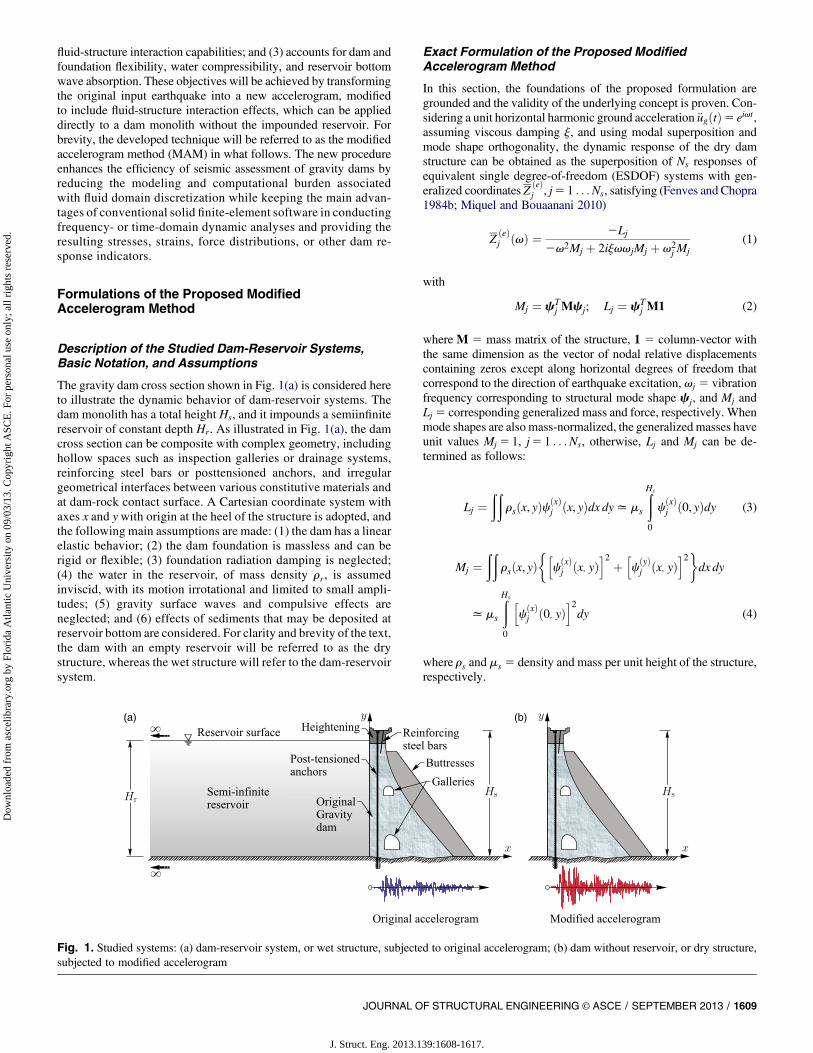
The gravity dam cross section shown in Fig. 1(a) is considered hereto illustrate the dynamic behavior of dam-reservoir systems. Thedam monolith has a total height Hs, and it impounds a semiinfinitereservoir of constant depth Hr. As illustrated in Fig. 1(a), the damcross section can be composite with complex geometry, includinghollow spaces such as inspection galleries or drainage systems,reinforcing steel bars or posttensioned anchors, and irregulargeometrical interfaces between various constitutive materials andat dam-rock contact surface. A Cartesian coordinate system withaxes x and y with origin at the heel of the structure is adopted, andthe following main assumptions are made: (1) the dam has a linearelastic behavior; (2) the dam foundation is massless and can berigid or flexible; (3) foundation radiation damping is neglected;(4) the water in the reservoir, of mass density rr, is assumedinviscid, with its motion irrotational and limited to small ampli-tudes; (5) gravity surface waves and compulsive effects areneglected; and (6) effects of sediments that may be deposited atreservoir bottom are considered. For clarity and brevity of the text,the dam with an empty reservoir will be referred to as the drystructure, whereas the wet structure will refer to the dam-reservoirsystem.
Exact Formulation of the Proposed ModifiedAccelerogram Method
In this section, the foundations of the proposed formulation aregrounded and the validity of the underlying concept is proven. Con-sidering a unit horizontal harmonic ground acceleration €ugðtÞ5 eivt,assuming viscous damping j, and using modal superposition andmode shape orthogonality, the dynamic response of the dry damstructure can be obtained as the superposition of Ns responses ofequivalent single degree-of-freedom (ESDOF) systems with gen-eralized coordinates Z
ðeÞj , j5 1 . . .Ns, satisfying (Fenves and Chopra
1984b; Miquel and Bouaanani 2010)
ZðeÞj ðvÞ ¼ 2Lj
2v2Mj þ 2ijvvjMj þ v2j Mj
(1)
with
Mj ¼ cTj Mcj; Lj ¼ cT
j M1 (2)
where M 5 mass matrix of the structure, 1 5 column-vector withthe same dimension as the vector of nodal relative displacementscontaining zeros except along horizontal degrees of freedom thatcorrespond to the direction of earthquake excitation, vj 5 vibrationfrequency corresponding to structural mode shape cj, and Mj andLj 5 corresponding generalized mass and force, respectively. Whenmode shapes are also mass-normalized, the generalized masses haveunit values Mj 5 1, j5 1 . . .Ns, otherwise, Lj and Mj can be de-termined as follows:
Lj ¼ðð
rsðx, yÞcðxÞj ðx, yÞdx dyxms
ðHs
0
cðxÞj ð0, yÞdy (3)
Mj ¼ðð
rsðx, yÞ�h
cðxÞj ðx, yÞ
i2 þ hcðyÞj ðx, yÞ
i2�dx dy
xms
ðHs
0
hcðxÞj ð0, yÞ
i2dy (4)
where rs and ms 5 density and mass per unit height of the structure,respectively.
Fig. 1. Studied systems: (a) dam-reservoir system, or wet structure, subjected to original accelerogram; (b) dam without reservoir, or dry structure,subjected to modified accelerogram
JOURNAL OF STRUCTURAL ENGINEERING © ASCE / SEPTEMBER 2013 / 1609
J. Struct. Eng. 2013.139:1608-1617.
Dow
nloa
ded
from
asc
elib
rary
.org
by
Flor
ida
Atla
ntic
Uni
vers
ity o
n 09
/03/
13. C
opyr
ight
ASC
E. F
or p
erso
nal u
se o
nly;
all
righ
ts r
eser
ved.
When fluid-structure interaction is included, the vector Z offrequency-dependent generalized coordinates Zj, j5 1 . . .Ns, can beobtained by solving the system of equations (Fenves and Chopra1984b; Miquel and Bouaanani 2010)
SZ ¼ Q (5)
in which, for m5 1 . . .Ns and j5 1 . . .Ns
Sj,mðvÞ ¼�2v2 þ 2ijvvj þ v2
j
�Mjdj,m 2v2qj,mðvÞ (6)
Qm ¼ 2Lm þ GmðvÞ (7)
where dj,m 5 Kronecker symbol and where
qj,mðvÞ ¼ 2
ðHr
0
pjð0, y,vÞcðxÞm ð0, yÞdy (8)
GmðvÞ ¼ðHr
0
p0ð0, y,vÞcðxÞm ð0, yÞdy (9)
with p0 and pj 5 hydrodynamic pressures caused by the rigid andflexiblemotions of the dam, respectively, as defined in theAppendixfor convenient reference.
The previous equations were developed for a unit horizontalharmonic ground acceleration €ugðtÞ5 eivt. In the general case, theFourier transform of a given ground acceleration €ugðtÞ can be de-termined as
€ugðvÞ ¼ðta0
€ugðtÞe2ivtdt (10)
in which ta 5 time duration of the applied accelerogram. For eachmode j5 1 . . .Ns, ground acceleration €ug produces the following
modal displacements uðeÞj and accelerations €uðeÞj of the dry structure
[subscript (e) refers to empty reservoir hereafter], and modal dis-placements uj and accelerations €uj of the wet structure
u ðeÞj ðx, y,vÞ ¼ €ugðvÞZ ðeÞ
j ðvÞcjðx, yÞ;
€uðeÞj ðx, y,vÞ ¼ 2€ugðvÞv2Z
ðeÞj ðvÞcjðx, yÞ
(11)
ujðx, y,vÞ ¼ €ugðvÞZjðvÞcjðx, yÞ;€ujðx, y,vÞ ¼ 2€ugðvÞv2ZjðvÞcjðx, yÞ
(12)
Defining a mode- and frequency-dependent ground acceleration að jÞgso that
a ð jÞg ðvÞZ ðeÞ
j ðvÞcjðx, yÞ ¼ €ugðvÞZjðvÞcjðx, yÞ (13)
yields to
að jÞg ðvÞ ¼ €ugðvÞ ZjðvÞZðeÞj ðvÞ
(14)
Applying Fourier inverse to this modal acceleration, Ns mode-dependent accelerograms are obtained, each given by
að jÞg ðtÞ ¼ 12p
ð‘2‘
aðjÞg ðvÞeivtdv (15)
Executing Ns finite-element modal analyses for every modej5 1 . . .Ns of the dry structure subjected to respective groundmotions að jÞg and adding up the solutions lead to the response of thewet structure. As can be seen, this new formulation converts theanalysis of the wet structure subjected to a ground acceleration€ug into Ns analyses of the dry structure subjected to ground ac-celerations að jÞg , j5 1 . . .Ns, obtained through modification of theoriginal ground acceleration €ug. This process justifies the desig-nationMAMgiven to this technique. The formulation can be used toinclude the complex effects of fluid-structure interaction through afinite-element analysis of the dry structure as illustrated in Fig. 1(b).The analyst may decide, depending on analysis purposes, to usea simplified equivalent stickmodelmade of beam elements or amorecomplex finite-element model based on the detailed geometry of thestudied structure. In fact, the idea behind the MAM is to give theanalyst the freedom to use the finite-element program or model ofchoice, so he can (1) maximize the efficiency of state-of-the artoptimized pre- and postprocessing tools and functionalities em-bedded inmost finite-element software and (2) couple this efficiencywith the high performance of the reservoir analytical model includeddirectly in the input modified accelerogram.
As will be shown later, the MAM requires only a few structuralmodes to obtain convergence. The formulation presented in thissection is referred to as exact because it yields exactly the sameresults as the substructuringmethod proposed by Fenves andChopra(1984b). In the next section, a more efficient simplified formulationof the MAM is proposed, where the modified accelerogram is modeindependent, and the generalized coordinates are obtained througha simplified solution.
Simplified Formulation of the Proposed ModifiedAccelerogram Method
In the previous section, it was shown that the exact formulation ofthe MAM requires the execution of Ns dynamic analyses of the drystructure with each analysis using a mode-dependent modifiedaccelerogram að jÞg , j5 1 . . .Ns. In this section, a simplified formu-lation is proposed where only one mode-independent modifiedaccelerogram is required, thus allowing a single dynamic analysis ofthe dry structure. The total displacements uðeÞðx, y,vÞ and uðx, y,vÞwithin the dry and wet structures, respectively, can be written as
uðeÞðx, y,vÞ ¼ €ugðvÞPNs
j¼1ZðeÞj ðvÞcjðx, yÞ (16)
uðx, y,vÞ ¼ €ugðvÞPNs
j¼1ZjðvÞcjðx, yÞ (17)
Next, a mode-independent accelerogram ag is defined so that
agðx, y,vÞPNs
j¼1ZðeÞj ðvÞcjðx, yÞ ¼ €ugðvÞPNs
j¼1ZjðvÞcjðx, yÞ (18)
yielding
agðx, y,vÞ ¼ €ugðvÞ
PNs
j¼1ZjðvÞcjðx, yÞ
PNs
j¼1ZðeÞj ðvÞcjðx, yÞ
(19)
1610 / JOURNAL OF STRUCTURAL ENGINEERING © ASCE / SEPTEMBER 2013
J. Struct. Eng. 2013.139:1608-1617.
Dow
nloa
ded
from
asc
elib
rary
.org
by
Flor
ida
Atla
ntic
Uni
vers
ity o
n 09
/03/
13. C
opyr
ight
ASC
E. F
or p
erso
nal u
se o
nly;
all
righ
ts r
eser
ved.
Instead of depending on mode shape j as the accelerogram að jÞgdefined previously in Eq. (14), the new accelerogram ag is a functionof coordinates x and y where the mode shapes are evaluated. Thedisplacements of the wet structure subjected to accelerogram ag canbe expressed as
uðx, y,vÞ ¼ agðx, y,vÞPNs
j¼1ZðeÞj ðvÞcjðx, yÞ (20)
¼ €ugðvÞ
PNs
j¼1ZjðvÞcjðx, yÞ
PNs
j¼1ZðeÞj ðvÞcjðx, yÞ
PNs
j¼1ZðeÞj ðvÞcjðx, yÞ (21)
It is numerically shown that the following approximation yieldsexcellent results:
uðx, y,vÞ� €ugðvÞ
PNs
j¼1ZjðvÞ
PNs
j¼1ZðeÞj ðvÞ
PNs
j¼1ZðeÞj ðvÞcjðx, yÞ (22)
The validity of this simplification will be illustrated later for variousdam-reservoir systems. Accordingly, a simplified modified accel-erogram ~ag can be computed as follows:
~agðvÞ ¼ €ugðvÞ
PNs
j¼1ZjðvÞ
PNs
j¼1ZðeÞj ðvÞ
(23)
Introducing this frequency-dependent and coordinate-independentacceleration into Eq. (15) yields the simplified mode- andcoordinate-independent accelerogram ~agðtÞ that can be directlyapplied to the dry structure to obtain the corresponding dynamicresponse of the wet structure.
The matrices and system in Eq. (5) have to be, respectively,computed and solved for a large number of frequencies to ensureadequate convergence in the time domain. To increase computa-tional efficiency, a simplified method is proposed hereafter to obtainthe generalized coordinatesZj, j5 1 . . .Ns, instead of solvingEq. (5)using amatrix analysis numerical solution scheme. In a fundamental
mode analysis, i.e., Ns 5 1, the only generalized coordinate Z1 isgiven by
Z1ðvÞ ¼ Q1ðvÞS1,1ðvÞ
(24)
When two structural modes are to be included, the generalizedcoordinates can be obtained as
Z1ðvÞ ¼ S2,2ðvÞQ1ðvÞ2 S2,1ðvÞQ2ðvÞS1,1ðvÞS2,2ðvÞ2 S
22,1ðvÞ
(25)
Z2ðvÞ ¼ S1,1ðvÞQ2ðvÞ2 S2,1ðvÞQ1ðvÞS1,1ðvÞS2,2ðvÞ2 S
22,1ðvÞ
(26)
Finally, if higher-mode effects are to be included in the analysis,i.e.,Ns $ 3, it is shown based on extensive numerical experiments ontypical gravity dam sections that the generalized coordinates can beapproximated by decoupling the system of Eq. (5) as follows:
Z1ðvÞ � S2,2ðvÞQ1ðvÞ2 S2,1ðvÞQ2ðvÞS1,1ðvÞS2,2ðvÞ2 S
22,1ðvÞ
(27)
ZjðvÞ �Sj21, j21ðvÞQjðvÞ2 Sj, j21ðvÞQj21ðvÞ
Sj21, j21ðvÞSj, jðvÞ2 S2j, j2 1ðvÞ
for j ¼ 2 . . .Ns
(28)
The parameters Sj,m and Qm in Eqs. (24)–(28) are given by Eqs. (6)and (7) for j,m5 1 . . .Ns. Using the previous decoupling scheme, itis shown that only parameters qj, j21, qj, j, and Gj from Eqs. (8) and(9) are required to determine Zj for j5 1 . . .Ns. Simplifiedexpressions are developed next to evaluate these terms. The tech-nique used is based on the approach proposed by Bouaanani andPerrault (2010) consisting of approximating the x-component ofmode shapecj of the dry structure by a polynomial function of orderNcj
and coefficients aj,k as illustrated in Fig. 2
cðxÞj
�0, y
�� PNcj
k¼0aj,ky
k (29)
where y5 y=Hs. When dam foundation flexibility is neglected, themode shapes of the dam on a rigid foundation are considered and
Fig. 2. Approximation of the mode shapes of a gravity dam-foundation system
JOURNAL OF STRUCTURAL ENGINEERING © ASCE / SEPTEMBER 2013 / 1611
J. Struct. Eng. 2013.139:1608-1617.
Dow
nloa
ded
from
asc
elib
rary
.org
by
Flor
ida
Atla
ntic
Uni
vers
ity o
n 09
/03/
13. C
opyr
ight
ASC
E. F
or p
erso
nal u
se o
nly;
all
righ
ts r
eser
ved.
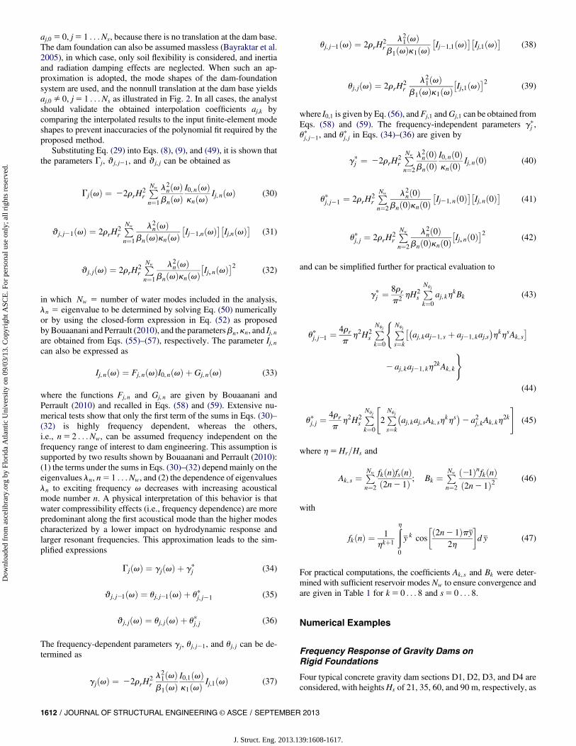
aj,0 5 0, j5 1 . . .Ns, because there is no translation at the dam base.The dam foundation can also be assumed massless (Bayraktar et al.2005), in which case, only soil flexibility is considered, and inertiaand radiation damping effects are neglected. When such an ap-proximation is adopted, the mode shapes of the dam-foundationsystem are used, and the nonnull translation at the dam base yieldsaj,0 � 0, j5 1 . . .Ns as illustrated in Fig. 2. In all cases, the analystshould validate the obtained interpolation coefficients aj,k bycomparing the interpolated results to the input finite-element modeshapes to prevent inaccuracies of the polynomial fit required by theproposed method.
Substituting Eq. (29) into Eqs. (8), (9), and (49), it is shown thatthe parameters Gj, qj, j21, and qj, j can be obtained as
GjðvÞ ¼ 22rrH2rPNw
n¼1
l2nðvÞbnðvÞ
I0, nðvÞknðvÞ Ij, nðvÞ (30)
qj, j21ðvÞ ¼ 2rrH2rPNw
n¼1
l2nðvÞbnðvÞknðvÞ
�Ij21,nðvÞ
�Ij,nðvÞ
(31)
qj, jðvÞ ¼ 2rrH2rPNw
n¼1
l2nðvÞbnðvÞknðvÞ
�Ij, nðvÞ
2(32)
in which Nw 5 number of water modes included in the analysis,ln 5 eigenvalue to be determined by solving Eq. (50) numericallyor by using the closed-form expression in Eq. (52) as proposedbyBouaanani and Perrault (2010), and the parametersbn,kn, and Ij, nare obtained from Eqs. (55)–(57), respectively. The parameter Ij, ncan also be expressed as
Ij, nðvÞ ¼ Fj, nðvÞI0, nðvÞ þ Gj, nðvÞ (33)
where the functions Fj, n and Gj, n are given by Bouaanani andPerrault (2010) and recalled in Eqs. (58) and (59). Extensive nu-merical tests show that only the first term of the sums in Eqs. (30)–(32) is highly frequency dependent, whereas the others,i.e., n5 2 . . .Nw, can be assumed frequency independent on thefrequency range of interest to dam engineering. This assumption issupported by two results shown by Bouaanani and Perrault (2010):(1) the terms under the sums in Eqs. (30)–(32) depend mainly on theeigenvalues ln, n5 1 . . .Nw, and (2) the dependence of eigenvaluesln to exciting frequency v decreases with increasing acousticalmode number n. A physical interpretation of this behavior is thatwater compressibility effects (i.e., frequency dependence) are morepredominant along the first acoustical mode than the higher modescharacterized by a lower impact on hydrodynamic response andlarger resonant frequencies. This approximation leads to the sim-plified expressions
GjðvÞ ¼ gjðvÞ þ gpj (34)
qj, j21ðvÞ ¼ uj, j21ðvÞ þ upj, j21 (35)
qj, jðvÞ ¼ uj, jðvÞ þ upj, j (36)
The frequency-dependent parameters gj, uj, j21, and uj, j can be de-termined as
gjðvÞ ¼ 22rrH2rl21ðvÞb1ðvÞ
I0,1ðvÞk1ðvÞ Ij,1ðvÞ (37)
uj, j21ðvÞ ¼ 2rrH2r
l21ðvÞb1ðvÞk1ðvÞ
�Ij21,1ðvÞ
�Ij,1ðvÞ
(38)
uj, jðvÞ ¼ 2rrH2r
l21ðvÞb1ðvÞk1ðvÞ
�Ij,1ðvÞ
2 (39)
where I0,1 is given by Eq. (56), andFj,1 andGj,1 can be obtained fromEqs. (58) and (59). The frequency-independent parameters gp
j ,upj, j21, and upj, j in Eqs. (34)–(36) are given by
gpj ¼ 22rrH2rPNw
n¼2
l2nð0Þbnð0Þ
I0, nð0Þknð0Þ Ij, nð0Þ (40)
upj, j21 ¼ 2rrH2rPNw
n¼2
l2nð0Þbnð0Þknð0Þ
�Ij21, nð0Þ
�Ij, nð0Þ
(41)
upj, j ¼ 2rrH2rPNw
n¼2
l2nð0Þbnð0Þknð0Þ
�Ij, nð0Þ
2(42)
and can be simplified further for practical evaluation to
gpj ¼8rrp2 hH2
sPNcj
k¼0aj, kh
kBk (43)
upj, j21 ¼4rrp
h2H2sPNcj
k¼0
(PNcj
s¼k
��aj, kaj21, s þ aj21, kaj,s
�hkhsAk, s
2 aj, kaj21, kh2kAk, k
)
(44)
upj, j ¼4rrp
h2H2sPNcj
k¼0
"2PNcj
s¼k
�aj, kaj, sAk, sh
khs�2 a2j, kAk, kh
2k
#(45)
where h5Hr=Hs and
Ak, s ¼ PNw
n¼2
fkðnÞfsðnÞð2n2 1Þ ; Bk ¼ PNw
n¼2
ð21ÞnfkðnÞð2n2 1Þ2 (46)
with
fkðnÞ ¼ 1hkþ1
ðh0
y k cos
ð2n2 1Þpy2h
�d y (47)
For practical computations, the coefficients Ak, s and Bk were deter-mined with sufficient reservoir modes Nw to ensure convergence andare given in Table 1 for k5 0 . . . 8 and s5 0 . . . 8.
Numerical Examples
Frequency Response of Gravity Dams onRigid Foundations
Four typical concrete gravity dam sections D1, D2, D3, and D4 areconsidered, with heightsHs of 21, 35, 60, and 90 m, respectively, as
1612 / JOURNAL OF STRUCTURAL ENGINEERING © ASCE / SEPTEMBER 2013
J. Struct. Eng. 2013.139:1608-1617.
Dow
nloa
ded
from
asc
elib
rary
.org
by
Flor
ida
Atla
ntic
Uni
vers
ity o
n 09
/03/
13. C
opyr
ight
ASC
E. F
or p
erso
nal u
se o
nly;
all
righ
ts r
eser
ved.
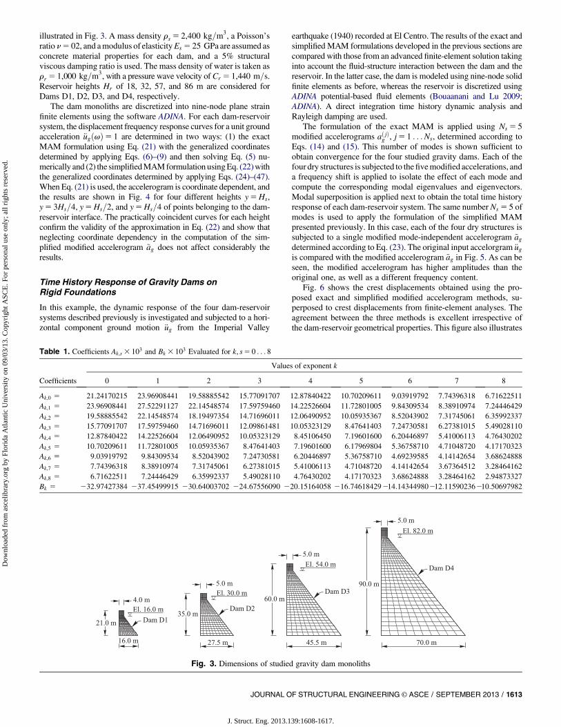
illustrated in Fig. 3. A mass density rs 5 2,400 kg=m3, a Poisson’sratio n5 02, and amodulus of elasticityEs 5 25 GPa are assumed asconcrete material properties for each dam, and a 5% structuralviscous damping ratio is used. The mass density of water is taken asrr 5 1,000 kg=m3, with a pressure wave velocity of Cr 5 1,440 m=s.Reservoir heights Hr of 18, 32, 57, and 86 m are considered forDams D1, D2, D3, and D4, respectively.
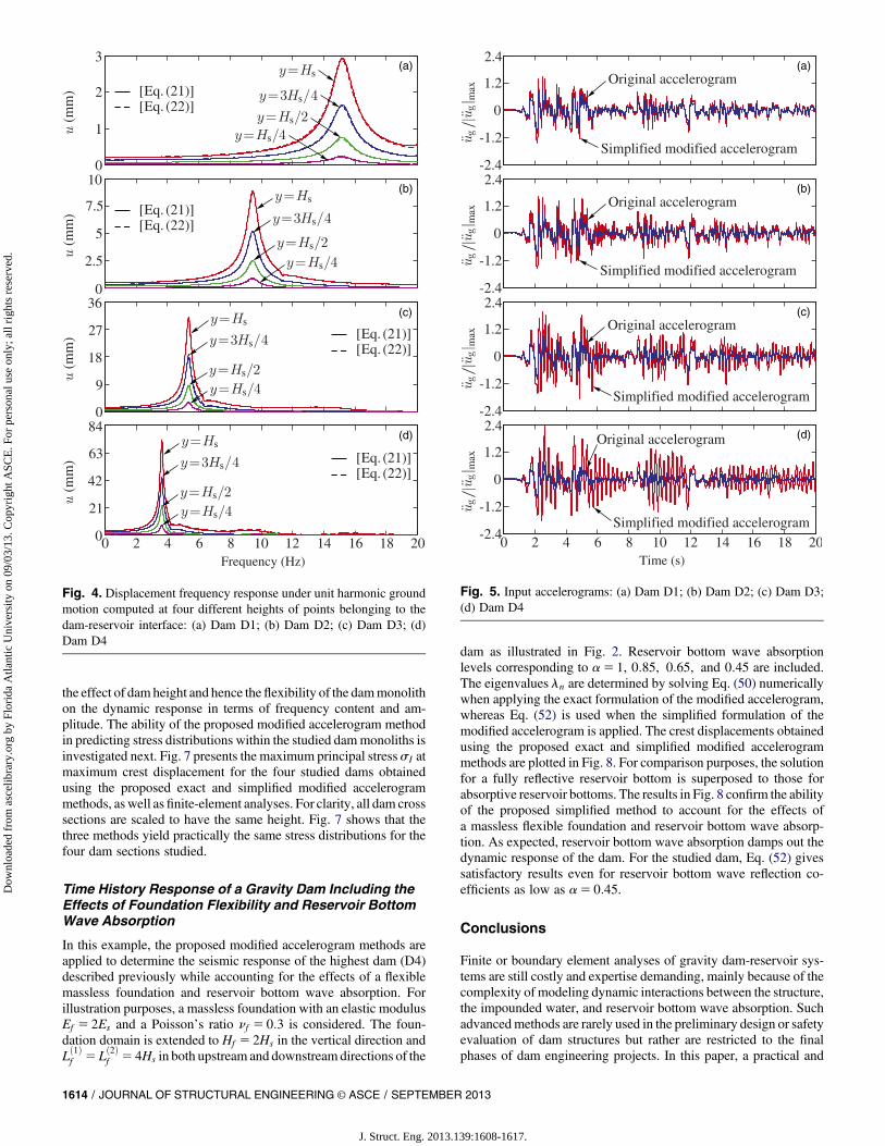
The dam monoliths are discretized into nine-node plane strainfinite elements using the software ADINA. For each dam-reservoirsystem, the displacement frequency response curves for a unit groundacceleration €ugðvÞ5 1 are determined in two ways: (1) the exactMAM formulation using Eq. (21) with the generalized coordinatesdetermined by applying Eqs. (6)–(9) and then solving Eq. (5) nu-merically and (2) the simplifiedMAMformulation usingEq. (22)withthe generalized coordinates determined by applying Eqs. (24)–(47).When Eq. (21) is used, the accelerogram is coordinate dependent, andthe results are shown in Fig. 4 for four different heights y5Hs,y5 3Hs=4, y5Hs=2, and y5Hs=4 of points belonging to the dam-reservoir interface. The practically coincident curves for each heightconfirm the validity of the approximation in Eq. (22) and show thatneglecting coordinate dependency in the computation of the sim-plified modified accelerogram ~ag does not affect considerably theresults.
Time History Response of Gravity Dams onRigid Foundations
In this example, the dynamic response of the four dam-reservoirsystems described previously is investigated and subjected to a hori-zontal component ground motion €ug from the Imperial Valley
earthquake (1940) recorded at El Centro. The results of the exact andsimplified MAM formulations developed in the previous sections arecompared with those from an advanced finite-element solution takinginto account the fluid-structure interaction between the dam and thereservoir. In the latter case, the dam is modeled using nine-node solidfinite elements as before, whereas the reservoir is discretized usingADINA potential-based fluid elements (Bouaanani and Lu 2009;ADINA). A direct integration time history dynamic analysis andRayleigh damping are used.
The formulation of the exact MAM is applied using Ns 5 5modified accelerograms að jÞg , j5 1 . . .Ns, determined according toEqs. (14) and (15). This number of modes is shown sufficient toobtain convergence for the four studied gravity dams. Each of thefour dry structures is subjected to thefivemodified accelerations, anda frequency shift is applied to isolate the effect of each mode andcompute the corresponding modal eigenvalues and eigenvectors.Modal superposition is applied next to obtain the total time historyresponse of each dam-reservoir system. The same number Ns 5 5 ofmodes is used to apply the formulation of the simplified MAMpresented previously. In this case, each of the four dry structures issubjected to a single modified mode-independent accelerogram ~agdetermined according to Eq. (23). The original input accelorgram €ugis compared with the modified accelerogram ~ag in Fig. 5. As can beseen, the modified accelerogram has higher amplitudes than theoriginal one, as well as a different frequency content.
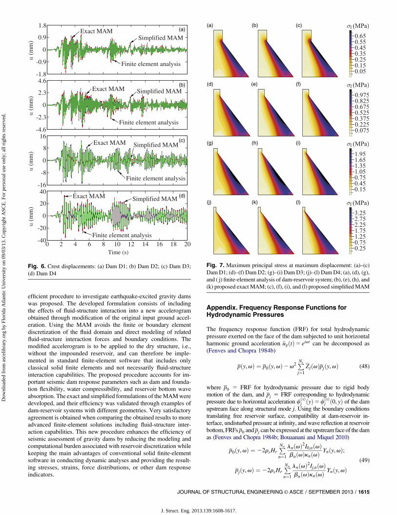
Fig. 6 shows the crest displacements obtained using the pro-posed exact and simplified modified accelerogram methods, su-perposed to crest displacements from finite-element analyses. Theagreement between the three methods is excellent irrespective ofthe dam-reservoir geometrical properties. This figure also illustrates
Table 1. Coefficients Ak,s 3 103 and Bk 3 103 Evaluated for k, s5 0 . . . 8
Values of exponent k
Coefficients 0 1 2 3 4 5 6 7 8
Ak,0 5 21.24170215 23.96908441 19.58885542 15.77091707 12.87840422 10.70209611 9.03919792 7.74396318 6.71622511Ak,1 5 23.96908441 27.52291127 22.14548574 17.59759460 14.22526604 11.72801005 9.84309534 8.38910974 7.24446429Ak,2 5 19.58885542 22.14548574 18.19497354 14.71696011 12.06490952 10.05935367 8.52043902 7.31745061 6.35992337Ak,3 5 15.77091707 17.59759460 14.71696011 12.09861481 10.05323129 8.47641403 7.24730581 6.27381015 5.49028110Ak,4 5 12.87840422 14.22526604 12.06490952 10.05323129 8.45106450 7.19601600 6.20446897 5.41006113 4.76430202Ak,5 5 10.70209611 11.72801005 10.05935367 8.47641403 7.19601600 6.17969804 5.36758710 4.71048720 4.17170323Ak,6 5 9.03919792 9.84309534 8.52043902 7.24730581 6.20446897 5.36758710 4.69239585 4.14142654 3.68624888Ak,7 5 7.74396318 8.38910974 7.31745061 6.27381015 5.41006113 4.71048720 4.14142654 3.67364512 3.28464162Ak,8 5 6.71622511 7.24446429 6.35992337 5.49028110 4.76430202 4.17170323 3.68624888 3.28464162 2.94873327Bk 5 232:97427384 237:45499915 230:64003702 224:67556090 220:15164058 216:74618429214:14344980212:11590236210:50697982
Fig. 3. Dimensions of studied gravity dam monoliths
JOURNAL OF STRUCTURAL ENGINEERING © ASCE / SEPTEMBER 2013 / 1613
J. Struct. Eng. 2013.139:1608-1617.
Dow
nloa
ded
from
asc
elib
rary
.org
by
Flor
ida
Atla
ntic
Uni
vers
ity o
n 09
/03/
13. C
opyr
ight
ASC
E. F
or p
erso
nal u
se o
nly;
all
righ
ts r
eser
ved.
the effect of dam height and hence theflexibility of the dammonolithon the dynamic response in terms of frequency content and am-plitude. The ability of the proposed modified accelerogram methodin predicting stress distributions within the studied dammonoliths isinvestigated next. Fig. 7 presents the maximum principal stress sI atmaximum crest displacement for the four studied dams obtainedusing the proposed exact and simplified modified accelerogrammethods, as well as finite-element analyses. For clarity, all dam crosssections are scaled to have the same height. Fig. 7 shows that thethree methods yield practically the same stress distributions for thefour dam sections studied.
Time History Response of a Gravity Dam Including theEffects of Foundation Flexibility and Reservoir BottomWave Absorption
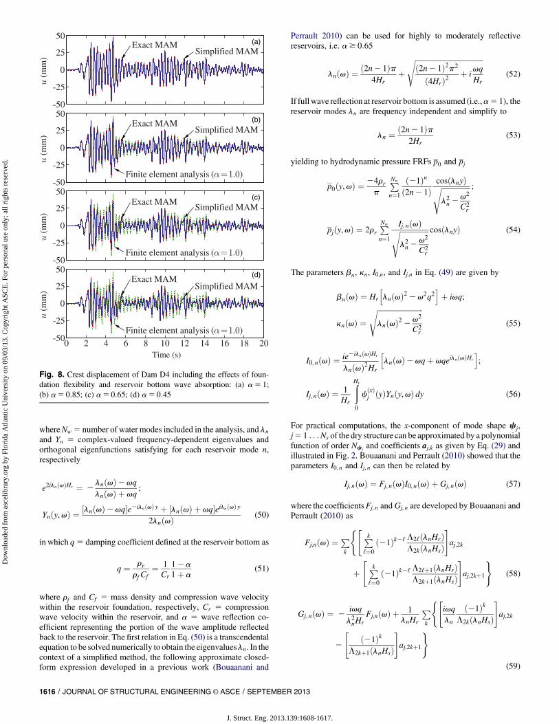
In this example, the proposed modified accelerogram methods areapplied to determine the seismic response of the highest dam (D4)described previously while accounting for the effects of a flexiblemassless foundation and reservoir bottom wave absorption. Forillustration purposes, a massless foundation with an elastic modulusEf 5 2Es and a Poisson’s ratio nf 5 0:3 is considered. The foun-dation domain is extended to Hf 5 2Hs in the vertical direction andLð1Þf 5 Lð2Þf 5 4Hs in both upstream and downstreamdirections of the
dam as illustrated in Fig. 2. Reservoir bottom wave absorptionlevels corresponding to a5 1, 0:85, 0:65, and 0:45 are included.The eigenvalues ln are determined by solving Eq. (50) numericallywhen applying the exact formulation of the modified accelerogram,whereas Eq. (52) is used when the simplified formulation of themodified accelerogram is applied. The crest displacements obtainedusing the proposed exact and simplified modified accelerogrammethods are plotted in Fig. 8. For comparison purposes, the solutionfor a fully reflective reservoir bottom is superposed to those forabsorptive reservoir bottoms. The results in Fig. 8 confirm the abilityof the proposed simplified method to account for the effects ofa massless flexible foundation and reservoir bottom wave absorp-tion. As expected, reservoir bottom wave absorption damps out thedynamic response of the dam. For the studied dam, Eq. (52) givessatisfactory results even for reservoir bottom wave reflection co-efficients as low as a5 0:45.
Conclusions
Finite or boundary element analyses of gravity dam-reservoir sys-tems are still costly and expertise demanding, mainly because of thecomplexity of modeling dynamic interactions between the structure,the impounded water, and reservoir bottom wave absorption. Suchadvancedmethods are rarely used in the preliminary design or safetyevaluation of dam structures but rather are restricted to the finalphases of dam engineering projects. In this paper, a practical and
Fig. 4. Displacement frequency response under unit harmonic groundmotion computed at four different heights of points belonging to thedam-reservoir interface: (a) Dam D1; (b) Dam D2; (c) Dam D3; (d)Dam D4
Fig. 5. Input accelerograms: (a) Dam D1; (b) Dam D2; (c) Dam D3;(d) Dam D4
1614 / JOURNAL OF STRUCTURAL ENGINEERING © ASCE / SEPTEMBER 2013
J. Struct. Eng. 2013.139:1608-1617.
Dow
nloa
ded
from
asc
elib
rary
.org
by
Flor
ida
Atla
ntic
Uni
vers
ity o
n 09
/03/
13. C
opyr
ight
ASC
E. F
or p
erso
nal u
se o
nly;
all
righ
ts r
eser
ved.
efficient procedure to investigate earthquake-excited gravity damswas proposed. The developed formulation consists of includingthe effects of fluid-structure interaction into a new accelerogramobtained through modification of the original input ground accel-eration. Using the MAM avoids the finite or boundary elementdiscretization of the fluid domain and direct modeling of relatedfluid-structure interaction forces and boundary conditions. Themodified accelerogram is to be applied to the dry structure, i.e.,without the impounded reservoir, and can therefore be imple-mented in standard finite-element software that includes onlyclassical solid finite elements and not necessarily fluid-structureinteraction capabilities. The proposed procedure accounts for im-portant seismic dam response parameters such as dam and founda-tion flexibility, water compressibility, and reservoir bottom waveabsorption. The exact and simplified formulations of theMAMweredeveloped, and their efficiency was validated through examples ofdam-reservoir systems with different geometries. Very satisfactoryagreement is obtained when comparing the obtained results to moreadvanced finite-element solutions including fluid-structure inter-action capabilities. This new procedure enhances the efficiency ofseismic assessment of gravity dams by reducing the modeling andcomputational burden associated with reservoir discretization whilekeeping the main advantages of conventional solid finite-elementsoftware in conducting dynamic analyses and providing the result-ing stresses, strains, force distributions, or other dam responseindicators.
Appendix. Frequency Response Functions forHydrodynamic Pressures
The frequency response function (FRF) for total hydrodynamicpressure exerted on the face of the dam subjected to unit horizontalharmonic ground acceleration €ugðtÞ5 eivt can be decomposed as(Fenves and Chopra 1984b)
pðy,vÞ ¼ p0ðy,vÞ2v2 PNs
j¼1ZjðvÞpjðy,vÞ (48)
where p0 5 FRF for hydrodynamic pressure due to rigid bodymotion of the dam, and pj 5 FRF corresponding to hydrodynamicpressure due to horizontal acceleration cðxÞ
j ðyÞ5cðxÞj ð0, yÞ of the dam
upstream face along structural mode j. Using the boundary conditionstranslating free reservoir surface, compatibility at dam-reservoir in-terface, undisturbed pressure at infinity, and wave reflection at reservoirbottom,FRFsp0 andpj can be expressed at the upstream face of the damas (Fenves and Chopra 1984b; Bouaanani and Miquel 2010)
p0ðy,vÞ ¼ 22rrHrPNw
n¼1
lnðvÞ2I0,nðvÞbnðvÞknðvÞ
Ynðy,vÞ;
pjðy,vÞ ¼ 22rrHrPNw
n¼1
lnðvÞ2Ij,nðvÞbnðvÞknðvÞ
Ynðy,vÞ(49)
Fig. 6. Crest displacements: (a) Dam D1; (b) Dam D2; (c) Dam D3;(d) Dam D4
Fig. 7. Maximum principal stress at maximum displacement: (a)–(c)Dam D1; (d)–(f) Dam D2; (g)–(i) Dam D3; (j)–(l) Dam D4; (a), (d), (g),and ( j) finite-element analysis of dam-reservoir system; (b), (e), (h), and(k) proposed exact MAM; (c), (f), (i), and (l) proposed simplifiedMAM
JOURNAL OF STRUCTURAL ENGINEERING © ASCE / SEPTEMBER 2013 / 1615
J. Struct. Eng. 2013.139:1608-1617.
Dow
nloa
ded
from
asc
elib
rary
.org
by
Flor
ida
Atla
ntic
Uni
vers
ity o
n 09
/03/
13. C
opyr
ight
ASC
E. F
or p
erso
nal u
se o
nly;
all
righ
ts r
eser
ved.
whereNw 5 number of water modes included in the analysis, and lnand Yn 5 complex-valued frequency-dependent eigenvalues andorthogonal eigenfunctions satisfying for each reservoir mode n,respectively
e2ilnðvÞHr ¼ 2lnðvÞ2vqlnðvÞ þ vq
;
Ynðy,vÞ ¼ ½lnðvÞ2vq�e2ilnðvÞ y þ ½lnðvÞ þ vq�eilnðvÞ y
2lnðvÞ (50)
in which q5 damping coefficient defined at the reservoir bottom as
q ¼ rrrf Cf
¼ 1Cr
12a1þ a
(51)
where rf and Cf 5 mass density and compression wave velocitywithin the reservoir foundation, respectively, Cr 5 compressionwave velocity within the reservoir, and a 5 wave reflection co-efficient representing the portion of the wave amplitude reflectedback to the reservoir. The first relation in Eq. (50) is a transcendentalequation to be solved numerically to obtain the eigenvaluesln. In thecontext of a simplified method, the following approximate closed-form expression developed in a previous work (Bouaanani and
Perrault 2010) can be used for highly to moderately reflectivereservoirs, i.e. a$ 0:65
lnðvÞ ¼ ð2n2 1Þp4Hr
þffiffiffiffiffiffiffiffiffiffiffiffiffiffiffiffiffiffiffiffiffiffiffiffiffiffiffiffiffiffiffiffiffiffiffiffiffiffið2n2 1Þ2p2
ð4HrÞ2þ i
vqHr
s(52)
If full wave reflection at reservoir bottom is assumed (i.e.,a5 1), thereservoir modes ln are frequency independent and simplify to
ln ¼ ð2n2 1Þp2Hr
(53)
yielding to hydrodynamic pressure FRFs p0 and pj
p0ðy,vÞ ¼24rrp
PNw
n¼1
ð21Þnð2n2 1Þ
cosðlnyÞffiffiffiffiffiffiffiffiffiffiffiffiffiffiffiffil2n2
v2
C2r
s ;
pjðy,vÞ ¼ 2rrPNw
n¼1
Ij, nðvÞffiffiffiffiffiffiffiffiffiffiffiffiffiffiffiffil2n2
v2
C2r
s cosðlnyÞ (54)
The parameters bn, kn, I0,n, and Ij,n in Eq. (49) are given by
bnðvÞ ¼ Hr
hlnðvÞ22v2q2
iþ ivq;
knðvÞ ¼ffiffiffiffiffiffiffiffiffiffiffiffiffiffiffiffiffiffiffiffiffiffiffiffiffilnðvÞ22v2
C2r
s(55)
I0, nðvÞ ¼ ie2ilnðvÞHr
lnðvÞ2Hr
hlnðvÞ2vqþ vqeilnðvÞHr
i;
Ij, nðvÞ ¼ 1Hr
ðHr
0
cðxÞj ðyÞYnðy,vÞ dy (56)
For practical computations, the x-component of mode shape cj,j5 1 . . .Ns of the dry structure can be approximated by a polynomialfunction of order Ncj
and coefficients aj,k as given by Eq. (29) andillustrated in Fig. 2. Bouaanani and Perrault (2010) showed that theparameters I0, n and Ij, n can then be related by
Ij, nðvÞ ¼ Fj, nðvÞI0, nðvÞ þ Gj, nðvÞ (57)
where the coefficientsFj, n andGj, n are developed by Bouaanani andPerrault (2010) as
Fj,nðvÞ ¼ Pk
(" Pkℓ¼0
ð21Þk2ℓ L2ℓðlnHrÞL2kðlnHsÞ
#aj,2k
þ" Pkℓ¼0
ð21Þk2ℓ L2ℓþ1ðlnHrÞL2kþ1ðlnHsÞ
#aj,2kþ1
)(58)
Gj, nðvÞ ¼ 2ivq
l2nHrFj,nðvÞ þ 1
lnHr
Pk
("ivqln
ð21ÞkL2kðlnHsÞ
#aj,2k
2
"ð21Þk
L2kþ1ðlnHsÞ
#aj,2kþ1
)
(59)
Fig. 8. Crest displacement of Dam D4 including the effects of foun-dation flexibility and reservoir bottom wave absorption: (a) a5 1;(b) a5 0:85; (c) a5 0:65; (d) a5 0:45
1616 / JOURNAL OF STRUCTURAL ENGINEERING © ASCE / SEPTEMBER 2013
J. Struct. Eng. 2013.139:1608-1617.
Dow
nloa
ded
from
asc
elib
rary
.org
by
Flor
ida
Atla
ntic
Uni
vers
ity o
n 09
/03/
13. C
opyr
ight
ASC
E. F
or p
erso
nal u
se o
nly;
all
righ
ts r
eser
ved.
in which lnðvÞ is noted as ln for clarity and the complex-valuedfunction Lm is defined as
LmðzÞ ¼ zm
m!(60)
Acknowledgments
The authors acknowledge the financial support of the Natural Scien-ces and Engineering Research Council of Canada (NSERC) and theQuebec Fund for Research on Nature and Technology (FQRNT).
References
ADINA version 8.8 [Computer software]. Watertown, MA, ADINAR & D, Inc.
Bayraktar, A., Hançer, E., and Akköse, M. (2005). “Influence of base-rockcharacteristics on the stochastic dynamic response of dam–reservoir–foundation systems.” Eng. Struct., 27(10), 1498–1508.
Bouaanani, N., and Lu, F. Y. (2009). “Assessment of potential-based fluidfinite elements for seismic analysis of dam–reservoir systems.” J. Comput.Struct., 87(3–4), 206–224.
Bouaanani, N., and Miquel, B. (2010). “A new formulation and erroranalysis for vibrating dam-reservoir systems with upstream transmittingboundary conditions.” J. Sound Vibrat., 329(10), 1924–1953.
Bouaanani, N., and Perrault, C. (2010). “Practical formulas for frequencydomain analysis of earthquake-induced dam-reservoir interaction.”J. Eng. Mech., 136(1), 107–119.
Chakrabarti, P., and Chopra, A. K. (1973). “Earthquake analysis of gravitydams including hydrodynamic interaction.” Earthquake Eng. Struct.Dynam., 2(2), 143–160.
Chopra, A. K. (1970). “Earthquake response of concrete gravity dams.”Rep.No. UCB/EERC-70/01, Univ. of California, Berkeley, CA.
Chopra, A. K. (1978). “Earthquake resistant design of concrete gravitydams.” J. Struct. Div., 104(6), 953–971.
Fenves, G., and Chopra, A. K. (1984a). “EAGD-84, a computer program forearthquake analysis of concrete gravity dams.”Rep. No. UCB/EERC-84/11, Univ. of California, Berkeley, CA.
Fenves, G., and Chopra, A. K. (1984b). “Earthquake analysis and responseof concrete gravity dams.” Rep. No. UCB/EERC-84/10, Univ. of Cal-ifornia, Berkeley, CA.
Fenves, G., and Chopra, A. K. (1987). “Simplified earthquake analysis ofconcrete gravity dams.” J. Struct. Eng., 113(8), 1688–1708.
Fok, K. L., Hall, J. F., and Chopra, A. K. (1986). “EACD-3D, a computerprogram for three-dimensional earthquake analysis of concrete dams.”Rep. No. UCB/EERC-86/09, Univ. of California, Berkeley, CA.
Hall, J. F., and Chopra, A. K. (1982). “Two-dimensional dynamic analysis ofconcrete gravity and embankment dams including hydrodynamic effects.”Earthquake Eng. Struct. Dynam., 10(2), 305–332.
Humar, J. L., and Jablonski, A. M. (1988). “Boundary element reservoirmodel for seismic analysis of gravity dams.” Earthquake Eng. Struct.Dynam., 16(8), 1129–1156.
Liu, P. H., and Cheng, A. (1984). “Boundary solutions for fluid-structureinteraction.” J. Hydraul. Eng., 110(1), 51–64.
Maeso, O., Aznarez, J. J., and Dominguez, J. (2004). “Three-dimensionalmodels of reservoir sediment and effects on the seismic response of archdams.” Earthquake Eng. Struct. Dynam., 33(10), 1103–1123.
Maity, D. (2005). “A novel far-boundary condition for the finite elementanalysis of infinite reservoir.” Appl. Math. Comput., 170(2),1314–1328.
Miquel, B., and Bouaanani, N. (2010). “Simplified evaluation of the vi-bration period and seismic response of gravity dam-water systems.”J. Eng. Struct., 32(8), 2488–2502.
Saini, S. S., Bettess, P., and Zienkiewicz, O. C. (1978). “Coupled hydro-dynamic response of concrete gravity dams using finite and infiniteelements.” Earthquake Eng. Struct. Dynam., 6(4), 363–374.
Sharan, S. K. (1985). “Finite element modelling of infinite reservoirs.”J. Eng. Mech., 111(12), 1457–1469.
Sommerfeld, A. (1949). Partial differential equations in physics, AcademicPress, New York.
Tsai, C. S., and Lee, G. C. (1987). “Arch dam-fluid interactions: By FEM-BEM and substructure concept.” Int. J. Numer. Methods Eng., 24(12),2367–2388.
Zienkiewicz, O. C., and Newton, R. E. (1969). “Coupled vibrationsof a structure submerged in a compressible fluid.” Int. Symp. onFinite Element Techniques, Institut Fur Statik und Dynamik DerLuft- und Raumfahrtkonstruktionen, Univ. of Stuttgart, Stuttgart,Germany.
JOURNAL OF STRUCTURAL ENGINEERING © ASCE / SEPTEMBER 2013 / 1617
J. Struct. Eng. 2013.139:1608-1617.
Dow
nloa
ded
from
asc
elib
rary
.org
by
Flor
ida
Atla
ntic
Uni
vers
ity o
n 09
/03/
13. C
opyr
ight
ASC
E. F
or p
erso
nal u
se o
nly;
all
righ
ts r
eser
ved.