Embed Size (px)
Citation preview

Accuracy Evaluation of Definitive Casts Obtained from Conventional and Digital Impression Methods for Kennedy
Class IV Partially Edentulous Maxillary Arches:an in Vitro Study
Thesis submitted in partial fulfillment of the requirement for the degree of Master of Science
Tufts University School of Dental Medicine
Thesis submitted by:
Moetaz Homsi, D.M.D

i
Thesis Committee
Hans Peter Weber DMD, Dr.Med.Dent. 1
Matthew Finkelman PhD 2
Yukio Kudara CDT, MDT 3
Khaled El Rafie DMD 4
Panos Papaspyridakos DDS, MS, PhD 5
1. Professor and Chairman, Division of Postgraduate Prosthodontics, Tufts Univer-
sity School of Dental Medicine, Boston, MA, USA.
2. Associate Professor, Department of Public Health and Community Service, Tufts
University School of Dental Medicine, Boston, MA, USA.
3. Technical Instructor and Laboratory Technician, Division of Postgraduate
Prosthodontics, Tufts University School of Dental Medicine, Boston, MA, USA.
4. Clinical Instructor, Division of Postgraduate Prosthodontics, Tufts University
School of Dental Medicine, Boston, MA, USA.
5. Assistant Professor, Division of Postgraduate Prosthodontics, Tufts University
School of Dental Medicine, Boston, MA, USA.

ii
ACKNOWLEDGEMENTS
The present study was supported by the Department of Post-Graduate Prosthodontics
at Tufts University School of Dental Medicine. The authors do not have any financial in-
terest in the companies whose materials are included in this article. This study was
done in partial fulfillment of the requirements for the Master of Science degree of Dr
Moetaz Homsi.
iii

Table of Contents
Abstract 1..................................................................................................................Thesis Committee ii..................................................................................................Acknowledgments iii.................................................................................................Introduction and Literature Review 3........................................................................Aim and Hypothesis 8...............................................................................................
Materials and Methods 8..........................................................................................Results 15.................................................................................................................Discussion 16...........................................................................................................Conclusion 19...........................................................................................................References 20..........................................................................................................Appendix A: Tables 27.............................................................................................Appendix B: Figures 29...........................................................................................
iv

Abstract:
Purpose: This study compared the accuracy of definitive casts obtained by conven-
tional impressions with those obtained from two different intra-oral scanners (Dental
Wings and True Definition).
Material and Methods: Two maxillary partially edentulous clear acrylic casts with
teeth # 7, 8, 9, and 10 missing were fabricated to simulate a Kennedy class IV clinical
condition. Both casts were outfitted with two internal connection implant analogs in sites
# 7 and 10, Bone Level RC implant analogs (Straumann USA, Andover, MA) in one
cast, and Nobel Conical Connection RP implant analogs (Nobel Biocare, Yorba Linda,
CA) in the other. The study had 6 groups. Groups I and II included casts produced from
conventional impressions, which were then digitized (n=10 each). Groups III and IV
consisted of digital impressions obtained with a 3Shape True Definition intra-oral scan-
ner (n=10 each). For groups V and VI a Dental Wings intra-oral scanner was used to
produce the digital impressions (n=10 each).
Results: For the Straumann implant system, the True Definition intra-oral scanner was
the most accurate with a median ± IQR 3-D deviation of 18.1 ± 4.7μm. No statistically
significant differences between the three groups (p = 0.400) were noted.
For the Nobel Biocare system, the Dental Wings intra-oral scanner was the most accu-
rate with a median ± IQR 3-D deviation of 15.9 ± 3.2μm. A statistically significant differ-
ence between the Dental Wings digital impression and the conventional impression
group, which had a median ± IQR of 25.3 ± 2.9 μm) was found.
The difference between Straumann and Nobel Biocare casts was significant for Dental
Wings digital impressions (p=0.023), but not for the other two impression techniques
�1

(p=0.579 for conventional, p=0.853 for True Definition).
Conclusions: Within the limitations of the current study, the Dental Wings intra-oral
scanner showed the least 3-D deviation for the Nobel Biocare implant system with a sta-
tistically significant difference when compared to the conventional impression method.
The True Definition scans showed the least 3-D deviations for the Straumann Bone
Level RC system, but no statistically significant differences between the three groups
were observed.
Dental Wings digital impressions showed less 3-D deviation values for the Nobel Bio-
care system than the Straumann system with a statistically significant difference.
�2

Introduction and Literature Review
The success of dental implants has been well documented in the literature. Conse-
quently, implant supported prostheses have become the preferred alternative for tooth
replacement in many partially or fully edentulous patients [1,2,3]. Since their introduc-
tion in the early 1980s, Computer-Assisted Design (CAD) and Computer-Assisted Man-
ufacturing (CAM) have advanced, and in the past 10 years have been incorporated
more and more in dental care and dental technology. Today, digital dental technology
provides a viable alternative to the conventional techniques of fabricating fixed implant-
supported prosthesis and has gained considerable popularity in implant dentistry
[4,5,6].
A passive fit is an important prerequisite for the long-term success of both implants and
the final prosthesis [7]. The fit is considered “passive” when the restoration does not
create static loads within the prosthetic system or in the surrounding bone tissue. Pas-
sive fit is very important for the long term success of both implants and prosthesis, and
it helps in minimizing both biological and prosthetic complications[1,7].
Multiple studies have defined passive fit. However, there is no agreement on the ac-
ceptable size of the marginal gap [8]. The marginal gap size at the interface between
the prosthesis and implant or abutment has been used to describe the level of fit. How-
ever, numbers that have been suggested as being acceptable are 10, 30, or 150 mi-
crons and have rendered this method as empirical. The screw resistance test proposed
by Jemt et al. represents another method [5]. If gap closure can be achieved by tighten-
�1

ing an occlusal screw with an extra one half of a turn of a screw, then the fit may be ac-
cepted as passive [7,8,9].
Multiple steps and procedures are performed before the final delivery of prosthesis. Ob-
taining an accurate working model that truly represents the implant location and orienta-
tion is a fundamental prerequisite for achieving an accurately fitting prosthesis.
There are several factors that affect the accuracy of a working or master cast such as
impression technique, implant type/system, implant-abutment connection type (external
vs. internal), stiffness and accuracy of fit of impression posts, implant depth relative to
the soft tissue level, and angulation between implants[10,11].
Multiple studies and systematic reviews have evaluated and compared the various
techniques for impression taking in partially edentulous patients.
For conventional impressions, it has been well documented that splinting the implant
transfer or impression posts with a resin-based material prior to obtaining the impres-
sions leads to superior accuracy of the resulting cast than with non-splinted alternatives
for both completely and partially edentulous arches. While for completely edentulous
arches open tray techniques have been shown to be more accurate than the closed-tray
techniques, no difference has been found for dental arches with posterior partial eden-
tulism [7,10,11,12,13]. However, for the specific indication of maxillary anterior partial
edentulism, the current scientific literature does not provide any information.
�2

Implant-prosthodontic treatment in the anterior maxilla is defined as advanced or com-
plex [15]. While multiple studies have shown that the success rate of implants placed in
the anterior maxilla is similar to other regions of the mouth[16,17], implant placement in
the anterior maxilla is challenging because of the anatomy of the alveolar ridge in the
area, and the bone remodeling processes after tooth extraction, which especially affect
the buccal alveolar bone.
It has been shown that following tooth extraction in the anterior maxilla, resorption of the
alveolar bone volume is 25% during the first year and 40-60% after 3 years [18]. Re-
sorption occurs in a palatal direction, which will often lead to palatal placement of the
implants relative to the prosthodontically desirable tooth position in the area if no graft-
ing procedures are performed.
If multiple adjacent teeth need to be replaced requiring the placement of two or more
implants, there is a high likelihood of having non-parallel implants, both in the mesio-dis-
tal and facial-palatal directions. Therefore, the scenario chosen in this study is of a clin-
ical relevance. In their study, Lin et al. [7] chose a Kennedy Class II scenario, i.e., distal
extension with implants being adjacent to natural teeth only on their mesial side. In a
Kennedy Class IV indication, implants are tooth bound both mesially and distally, which
may have an additional negative effect on the accuracy of impressions, casts, and/or
prostheses.
This study addressed the influence of two different implant designs – tissue level im-
�3

plants and bone level implants – on the accuracy of conventional and digital impres-
sions. The choice of implant type is usually based on clinician preference. Especially in
the anterior maxilla, bone level type implants are more frequently used. They offer mul-
tiple advantages, of which the most important are: easier surgical handling in combina-
tion with bone augmentation procedures; greater transmucosal running room for proper
emergence designs of provisional and final prostheses; and easier customization of final
crown margin locations and insertion paths via custom abutments.
In a recent systematic review regarding the incidence of biologic, technical, and esthetic
complications of single implant abutments supporting fixed prostheses, Zembic et al.
[19] reported a higher incidence of technical complications compared to biological or es-
thetic complications. This included abutment screw loosening, crown loosening, and
chipping of veneering ceramics. However, no differentiation was made between im-
plants placed in the posterior or anterior regions.
Visser et al. [20] evaluated the complications associated with implant retained crowns in
the maxillary esthetic region. These authors concluded that esthetic complications were
high. In 12% of the cases, a new restoration had to be made due to the inadequate
shape or color of the original crown.
As for complications associated with mal-aligned or tilted implants, Chrcanovic et al.
[21] in a recent review and meta-analysis concluded that the angulations of dental im-
plants in a mesio-distal direction might not affect implant survival in the maxilla. Howev-
er, they only evaluated biological complications. �4

Tiziano et al. [22] in a case series of 35 patients evaluated both biological and prosthet-
ic complications associated with tilted trans-sinus implants.
Patients were either completely or partially edentulous, and the final prosthesis were
either full arch fixed prosthesis or 3 unit fixed partial prosthesis. Prosthetic complications
associated with tilted implants were screw loosening in 17.5% of cases and porcelain
chipping in 30% of the cases.
Many companies are competing to develop the most accurate intraoral impression de-
vices. There are several scanning systems available today that use intraoral video data
acquisition:
- TRIOS by 3Shape (3Shape, Copenhagen, Denmark): this system works un-
der the principle of ultrafast optical sectioning and confocal microscopy, which recog-
nizes the pattern being scanned over a range of focus plane positions when maintaining
a fixed spatial relation between the scanner and the object being scanned.
- CEREC Omnicam (Dentsply - Sirona, Bensheim, Germany): this system
uses the triangulation of light, in which the intersection of three linear light beams is fo-
cused on a certain point in 3D space.
- True Definition by 3M ESPE (3M ESPE, St. Paul, MN): this system works
with the concept of active wavefront sampling. It is capable of obtaining 3D data from a
�5

single-lens imaging system.
- Dental Wings (Dental Wings, Montreal, QC): this system uses miniaturized 3D
scanners in the hand-piece tip, which directly view the teeth and/or implant scan bod-
ies, and surrounding soft tissues from multiple orientations. Captured data are trans-
mitted to an in-office or remote system via DWOS Connect for prosthesis design and
production. It is an open system compatible with other CAD software.
Once scanning is complete, the resulting data are saved either as a stereolithographic
Standard Tessilation Language (STL) file, or a proprietary encrypted file. An open sys-
tem uses STL files and will allow the use of any CAM device, while a closed system will
generate a proprietary encrypted file that can only be used by specific software and
milling devices from the same system.
Digital impressions using intra-oral scanners (IOS) have advantages over conventional
impressions in a number of ways: potential reduction of time from dental chair to dental
laboratory, digital processing and storage, online communication between dentist and
dental technologist, and improved patient comfort [10,15,16,17,18,23,24,25,26].
When evaluating the accuracy of digital implant impressions for partially edentulous pa-
tients, limited data are available [7,10,14]. In one study, Ng et al.[33] evaluated the ef-
fect of inter-implant angulation on the accuracy of a master model, and compared con-
ventional to digital techniques using the Robocast protocol (Biomet 3i, West Palm
�6

Beach, FL). Implants were placed in the mandibular first premolar and first molar posi-
tions simulating a Kennedy class III scenario. Inter-implant angulations of 0, 10, 20, and
30 degrees were studied. The casts obtained using the digital technique were less ac-
curate than those with a conventional impression for all tested inter-implant angulations.
In another study, Lin et al. [7] used the TRIOS intraoral scanner (3Shape, Copenhagen,
Denmark) to compare the accuracy of conventional and digital impressions for a fixed
dental prosthesis on tissue level implants placed in the posterior mandible, simulating a
Kennedy class II scenario with inter-implant angulations of 0, 15, and 30 degrees. At 0
and 15 degrees of implant divergence, the casts generated from digital impressions
were less accurate than those from conventional impressions. At 30 and 45 degrees,
there was no difference between the two methods [10]. However, little data are available
for the Dental Wings and True Definition intraoral scanners at this time, nor are there
any studies evaluating the accuracy of digital impressions for the Kennedy class IV sce-
nario with bone level implants placed in the anterior maxilla.
Due to the sparsity of scientific information regarding the accuracy of digital impressions
with intraoral scanners other than Trios or for the accuracy of digital impression tech-
niques in partially edentulous indications, it is desirable to evaluate other intraoral scan-
ning systems specifically for partially edentulous indications such as the Kennedy Class
IV scenario.
�7

Aim and Hypothesis
The purpose of this study was:
- to compare the accuracy of definitive casts obtained from conventional impressions
with digital implant impressions using 2 different intra-oral scanning systems (Dental
Wings and 3M True Definition).
- to compare the impression accuracy for two implant systems - Nobel Conical Connec-
tion RP and Straumann Bone Level - in the presence of 30° inter-implant divergence.
The proposed hypotheses for this study were:
1) Splinted open tray conventional impressions are more accurate than digital impres-
sions of dental arches with anterior partial edentulism and implants of ≥ 30º divergence.
2) There is no difference in impression accuracy between the two implant systems
studied under the conditions stated above.
Materials and Methods
Master Cast Fabrication
Two maxillary partially edentulous clear acrylic casts with teeth # 7, 8, 9, and 10 missing
were fabricated to simulate a Kennedy class IV clinical condition. Both casts were outfit-
ted with two internal connection implant analogs in sites # 7 and 10. In one cast, they
were Bone Level RC implant analogs (Straumann USA, Andover, MA), in the other No- �8

bel Conical Connection RP implant (Nobel Biocare, Yorba Linda, CA).
The implant analogs in both casts were placed with a mesiodistal divergence of 30 de-
grees. The analogs in sites 7 and 10 were tilted 15 degrees distally. One model per im-
plant system was fabricated from clear acrylic in a laboratory specialized in model man-
ufacturing (Model Plus Inc, Grayslake, II).
It is not possible to scan a clear acrylic model accurately, because the scanning light will
reflect from the acrylic surface. A large amount of scanning powder will have to be ap-
plied, which would compromise the accuracy. Therefore, a stone duplicate model was
fabricated, which served as the master cast in this study.
The master cast was fabricated as follows: impression copings were attached to the im-
plants in the clear acrylic model. Two openings were drilled in the custom tray for ac-
cess to the impression coping guide screws. The impression posts were splinted with
urethane-dimethacrylate-based visible light curing resin (Triad Gel; Dentsply Inc, York,
PA). Two layers of baseplate wax (Neowax; Dentsply Trubyte Inc, York, PA) were ap-
plied to the master cast to provide an equal thickness of 3 mm for the impression mater-
ial. Custom tray was fabricated using Triad TruTray (Dentsply Inc, York, PA). Impression
was obtained using polyether impression material (Impregum, 3M ESPE, St. Paul, MN).
After loosening the impression post screws and separating the impression from the
model, implant analogs were screwed to the impression copings and the impression
poured using a low expansion (0.09%) type IV die stone (Resin Rock, Whipmix Corp,
�9

Louisville, KY). As mentioned, the resulting cast served as the master model (control
model) for all study groups.
The following groups of casts I – VI were created and compared:
GROUP I (n=10): Casts generated from conventional splinted open-tray impres-
sions obtained at the implant level of Straumann Bone Level Regular Crossfit (Bl
RC) Implants (Straumann USA, Andover, MA)
GROUP II (n=10): Casts generated from conventional splinted open-tray impres-
sions obtained at the implant level of Nobel Biocare Regular Platform (RP) Im-
plants (Nobel Biocare, Yorba Linda, CA).
GROUP III (n=10): Casts generated from digital impressions at the implant level of
Straumann BL RC Implants (Straumann USA, Andover, MA) using the True Defi-
nition scanner (3M Espe, St.Paul, MN).
GROUP IV (n=10): Casts generated from digital impressions at the implant level
of Nobel Biocare RP implants using the True Definition intraoral scanner (3M
Espe, St.Paul, MN).
GROUP V (n=10): Casts generated from digital impressions at the implant level of
Straumann BL RC Implants (Straumann USA, Andover, MA) using the Dental
Wings intraoral scanner (Dental Wings, Montreal, QC, Canada).
�10

GROUP VI (n=10): Casts generated from digital impressions at the implant level
of Nobel Biocare RP implants using the Dental Wings intraoral scanner (Dental
Wings, Montreal, QC, Canada)
Conventional Impressions - Groups I,II
Fabrication of Custom Trays
For the conventional impressions, custom trays were fabricated using Triad TruTray
(Dentsply Inc, York, PA). After connecting the impression posts with the splints, two lay-
ers of baseplate wax (Neowax; Dentsply Trubyte Inc, York, PA) were applied to the
casts to provide an equal thickness of 3 mm for the impression material. The master
model was marked in four different areas with V-shape notches. These mark stops en-
sured the accurate seating and positioning of the custom tray. Two openings were
drilled in the custom tray for access to the impression coping guide screws.
Fabrication of Splints
The impression posts were splinted with urethane-dimethacrylate-based visible light
curing resin (Triad Gel; Dentsply Inc, York, PA). Drinking straws were filled with the ma-
terial in order to standardize the thickness and shape of the splint. After light curing, the
splints were stored for 24 h at room temperature and relative humidity of 50%.
The resin bars were sectioned and re-connected to the impression copings with a mini-
mal amount of Triad to reduce dimensional changes of the material in the curing
process [6].
�11

Impression and Cast Fabrication
After connecting the impression copings/posts to the implant analogs and fabricating the
splints on the control cast as described above, impressions were taken using polyether
impression material (Impregum, 3M ESPE, St. Paul, MN ). Prior to impression taking,
tray adhesive was applied in a thin layer to the intaglio surface of the custom tray. The
adhesive was allowed to dry for 15 min. All impressions were made at room tempera-
ture, with a relative humidity of 50%. Automatic mixing and dispensing system Pentamix
(3M ESPE, St.Paul, MN) was used. Impression material was injected around the im-
pression posts using Impregum Penta Elastomer syringe (3M ESPE, St.Paul, MN). The
custom tray was filled and seated using light finger pressure until the marked stops con-
tacted with the respective areas on the master cast. The impression material was al-
lowed to polymerize for 8 min.
To produce the casts from the obtained impressions, a control box was made with addi-
tion reaction silicone to create a silicone matrix for pouring the impression with dental
stone. This control box was used for pouring all the impressions in order to standardize
the amount of stone used for the fabrication of the stone casts as well as the shape and
volume of the casts. This process was repeated 10 times to produce 10 stone models
for each group.
�12

Digital Implant Impression Technique
Group III and IV - Digital impression with Active Triangulation tech-
nology
A blue light intraoral scanner (True Definition: 3M ESPE, St.Paul, MN) was used to ob-
tain ten digital scans of each master cast. All digital impressions were obtained at the
implant level. Implant scan bodies (Bone Level RC scan bodies, Straumann USA, An-
dover, MA) and Regular Platform (RP) scan bodies (Nobel Biocare, Yorba Linda, CA)
were attached to the implants on the master cast and hand-tightened. After the acquisi-
tion of ten repeated digital impressions per master cast, the digital scans were
exported as Standard Tesselation Language (STL) files and stored on an external hard
drive.
Group V and VI - Digital impression with Active Wavefront Sampling
Technology
A Dental Wings intraoral scanner (Dental Wings, Montreal, QC, Canada) was used to
obtain ten digital scans of each master cast representing the two different implant sys-
tems in the same manner as described above for Groups III and IV.
Stone Model Digitization
Before conducting any measurements, all stone models from groups I and II were
stored for one week at room temperature. Using a high-resolution extraoral scanner
(Activity 880 Scanner, Smart Optics, Bochum, Germany), scans were obtained for
Group I and II stone models and digitized for comparison with the digital impression
groups (III-VI). Scan bodies were attached to the implant analogs (Bone Level RC,
Straumann USA, Andover, MA) and Regular Platform (RP) (Nobel Biocare, Yorma Lin- �13

da, CA). After scanning of the first cast, scan bodies were removed and placed on the
second model. The same procedures of placing the scan bodies in the exact same posi-
tion and scanning them were done for all 10 casts. The resulting STL digital files were
saved for the next step in the manner mentioned above. All of the measuring devices
were calibrated prior to scanning process according to manufacturer’s instructions.
Accuracy Measurements
Geomagic Control 2015 software (3D systems, Morrisville, NC) was used to superim-
pose the STL digital files from each cast from each test group over the files from the
control groups. The method in analyzing the differences was performed by the software
through calculating the root mean square (RMS) error.
Power Calculation
A power calculation was performed via nQuery Advisor (Version 7.0). The calculation
indicated that a sample size of n=10 per group would yield a Type I error rate of 5% and
power greater than 99% for the comparison of impression techniques, using the data
from a study by Papaspyridakos et al. [10] for anticipated values.
Statistical Analysis
Descriptive statistics were computed that included medians and inter-quartile ranges for
each group (splinted open tray conventional impression, Dental Wings digital impres-
sions, and True Definition digital impressions for both implant systems [Straumann Bone
Level RC and Nobel Biocare Conical Connection RP]). Analysis of accuracy measure-
�14

ment differences between the three groups within each implant system was conducted
via nonparametric testing due to the non-normality of the data. Comparing the impres-
sion techniques to each other was done via two separate Kruskal-Wallis tests. Dunn’s
test alongside the Bonferroni correction was used for post-hoc tests. Three Mann-Whit-
ney U tests were used to compare the Nobel Biocare with the Straumann system, one
test for each impression technique. With the exception of tests employing the Bonferroni
correction, p-values less than 0.05 were considered significant. SPSS Version 22 was
used for all statistical analyses.
Results
The 3-D deviation values for each group were calculated and displayed in table 1.
Median ± inter-quartile ranges of the 3-D deviation for the Straumann Bone Level RC
implant analogs are shown in Table 2a. When comparing the three impression tech-
niques, True Definition was the most accurate (18.1 ± 4.7μm), followed by Dental Wings
(24.3 ± 19.8 µm), and lastly the conventional impression technique (28.9 ± 28.2 µm).
The Kruskal-Wallis test comparing the groups did not reveal any statistically significant
differences (p = 0.400).
Median ± inter-quartile ranges of the 3-D deviations for Nobel Biocare Conical Connec-
tion RP implant analogs are shown in Table 2b. When comparing the three impression
techniques, Dental Wings was the most accurate (15.9 ± 3.2μm), followed by True Defi-
nition (18.7 ± 9.9 µm), and lastly the conventional impressions (25.3 ± 2.9μm). The
Kruskal-Wallis test comparing the three groups revealed statistically significant differ-
�15

ences (p = 0.004). In post-hoc tests, the only statistically significant difference found
was between the Dental Wings and the conventional impression groups (p=0.001).
The difference between Straumann and Nobel Biocare systems was significant for Den-
tal Wings (p=0.023), but not for the other two impression techniques (p=0.579 for con-
ventional, p=0.853 for True Definition). Figure 1
Discussion
This study compared the accuracy of definitive casts obtained from conventional im-
pressions to those from two different intra-oral scanning systems, True Definition and
Dental Wings. The study is one of the first to compare the accuracy of gypsum models
from conventional implant impressions and digital impressions obtained by True Defini-
tion and Dental Wings intra-oral scanners. The clinical scenario studied here has not
been used in any other study. As mentioned above, other similar studies have used dif-
ferent intra-oral scanners [10] or tissue level implants in different clinical scenarios [28].
The obtained results indicate that the Dental Wings intra-oral scanner was the most ac-
curate for the Nobel Biocare conical connection RP Implant system. In contrast, for the
Straumann Bone Level RC Implant system, the True Definition intra-oral scanner was
the most accurate. However, within each system, the only statistically significant differ-
ences were found for the Nobel Biocare casts when comparing Dental Wings digital
scans with the casts obtained with the conventional impression technique.
When comparing digital impressions using True Definition intra-oral scanning, the
Straumann system showed a lower 3-D deviation median value than the Nobel Biocare �16

system. This could be attributed to the design of the scan bodies. The Straumann scan
body is cylindrical in shape with no undercuts and much easier to scan. The Nobel Bio-
care scan body has an undercut in the gingival portion, which makes it more difficult to
obtain accurate scans with the True Definition scanner. Nevertheles, it has to be recog-
nized that the observed difference was not statistically significant.
The problem described above was not encountered when using the Dental Wings intra-
oral scanner. The hand piece head is small and equipped with little wings. They make it
easier to image the undercut areas.
One more difference between the two scanning systems lies in the manner in which
each system processes the missing data following every scan. The True Definition
scanner will point to the areas that were not properly registered and requests a separate
scan to be made for these areas. Following the second scan the system attempts to
overlap the two scans. This step may affect the accuracy of the final scan. However,
with the Dental Wings scanner, the system will compensate for the missing data by au-
tomatically predicting and filling them in by comparison to similar areas that were al-
ready captured.
It has to be noted that both scanners require the use of scanning powder, a procedure
that is difficult to standardize. During scanning, powder was reapplied in areas that were
not recognized by the scanner at each subsequent scan. When the scanning powder is
being reapplied some of the areas might get sprayed twice which might affect the accu-
�17

racy.
The 3-D deviation of all impression techniques was less than 150 µm. Klinberg and Mur-
ray [35] stated that a 30 µm gap at the implant–abutment interface is acceptable if it is
not including more than 10% of the circumference. More recently, Jemt [5] stated that a
misfit around 150 µm is acceptable.
The accuracy of a dental impression is determined by two factors: trueness and preci-
sion (ISO 5725-1). Trueness represent the deviation from the control or original geome-
try. Precision represents the deviations within impressions of a test group. This study
looked at the accuracy (Trueness) of the three impression techniques.
The control stone master model was digitized using an Extra-Oral scanner (Activity 880
Scanner, Smart Optics, Bochum, Germany). According to the manufacturer the preci-
sion of the scanner is 10 µm, which might be considered a limitation of the study, other
studies have used different technologies for the digitization of the control model with a
precision of 1µm [36].
One last limitation of the current study is that before each scan with both intra-oral
scanners, the scan bodies were removed and replaced again to resemble the case of
the conventional impressions were scan bodies were moved between different stone
models. This process might lead to some inaccuracy due to the possibility of placing the
scan bodies in a different position, and the machinery intolerance of the two implants
systems.
�18

Digital impressions using intra-oral scanners, and the utilizing of CAD/CAM technology
are a predictable and viable option for the fabrication of implant restorations, from single
crown to full arch restoration, including a Kennedy class IV scenario as studied here. A
digital work flow can provide a faster and more efficient approach when compared with
conventional impression techniques. In one study, intra-oral scanning was 23 minutes
faster than obtaining conventional impressions for single crowns, 22 minutes faster for
3-Units FPD, and 13 minutes faster for full arch impressions with 13 abutments. [34].
Conclusions
Within the limitations of the current in vitro study the following can be concluded:
1- For the Straumann Bone Level RC implant system, there was no significant differ-
ence between the three impression techniques. However, True Definition intra-oral
scanner showed the least 3-D Deviation, while the conventional open tray splinted tech-
nique showed the most.
2- For the Nobel Biocare Conical Connection RP implant system, the Dental Wings in-
tra-oral scanner was found to be the most accurate, while the conventional open tray
splinted technique was the least accurate.
3- When comparing the two implant systems, impressions obtained with the Dental
Wings intra-oral scanner were more accurate for the Nobel Biocare than the Straumann
system.
�19
References
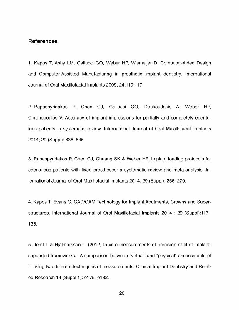
1. Kapos T, Ashy LM, Gallucci GO, Weber HP, Wismeijer D. Computer-Aided Design
and Computer-Assisted Manufacturing in prosthetic implant dentistry. International
Journal of Oral Maxillofacial Implants 2009; 24:110-117.
2. Papaspyridakos P, Chen CJ, Gallucci GO, Doukoudakis A, Weber HP,
Chronopoulos V. Accuracy of implant impressions for partially and completely edentu-
lous patients: a systematic review. International Journal of Oral Maxillofacial Implants
2014; 29 (Suppl): 836–845.
3. Papaspyridakos P, Chen CJ, Chuang SK & Weber HP. Implant loading protocols for
edentulous patients with fixed prostheses: a systematic review and meta-analysis. In-
ternational Journal of Oral Maxillofacial Implants 2014; 29 (Suppl): 256–270.
4. Kapos T, Evans C. CAD/CAM Technology for Implant Abutments, Crowns and Super-
structures. International Journal of Oral Maxillofacial Implants 2014 ; 29 (Suppl):117–
136.
5. Jemt T & Hjalmarsson L. (2012) In vitro measurements of precision of fit of implant-
supported frameworks. A comparison between “virtual” and “physical” assessments of
fit using two different techniques of measurements. Clinical Implant Dentistry and Relat-
ed Research 14 (Suppl 1): e175–e182.
�20

6. Papaspyridakos P & Lal K. (2013) Computer Assisted Design/Computer-assisted
Manufacturing zirconia implant fixed complete prostheses: clinical results and technical
complications up to 4 years of function. Clinical Oral Implants Research 24: 659–665.
7. Lin WS, Harris BT, Elathamna EN, Abdel-Azim T, Morton D. Effect of Implant Diver-
gence on the Accuracy of Definitive Casts Created from Traditional and Digital Implant-
Level Impressions: An In Vitro Comparative Study. International Journal of Oral Maxillo-
facial Implants 2015; 30:102-109.
8. Abduo J, Bennani V, Waddell N, Lyons K, Swain M. Assessing the fit of implant fixed
prostheses: A critical review. International Journal of Oral Maxillofacial Implants 2010;
25:506–515.
9. Sahin S, Cehreli MC. The significance of passive framework fit in implant prosthodon-
tics: Current status. Implant Dentistry 2001;10:85–92.
10. Papaspyridakos P, Gallucci GO, Chen CJ, Hanssen S, Naert I, Vandenberghe B.
Digital versus Conventional Implant Impressions for Edentulous Patients: Accuracy Out-
comes. Clinical Oral Implants Research. 00, 2015, 1-8 doi: 10.1111/clr.12567.
11. Akalin ZF, Ozkan YK, Ekerim A. Effects of implant angulation, impression material,
and variation in arch curvature width on implant transfer model accuracy. International
Journal of Oral Maxillofacial Implants 2013; 28:149–157.
�21

12. Mpikos P, Tortopidis D, Galanis C, Kaisarlis G, Koidis P. The effect of impression
technique and implant angulation on the impression accuracy of external and internal
connection implants. International Journal of Oral Maxillofacial Implants 2012; 27:1422–
1428.
13. Rutkunas V, Sveikata K, Savickas R. Effects of implant angulation, material selec-
tion, and impression technique on impression accuracy: A preliminary laboratory study.
International Journal of Prosthodontics 2012; 25:512–515.
14. Sorrentino R, Gherlone EF, Calesini G, Zarone F. Effect of implant angulation, con-
nection, length, and impression material on the dimensional accuracy of implant im-
pressions: An in vitro comparative study. Clinical Implant Dentistry and Related Re-
search 2010; 12S1:e63–76.
15. Buser D, Martin W, Belser UC. Optimizing esthetics for implant restorations in the
anterior maxilla: anatomic and surgical considerations. International Journal of Oral
Maxillofacial Implants 2004; 19 (Suppl):43-61.
16. Belter UC, Buser D, Higginbottom F. Consensus statements and recommended clin-
ical procedures regarding esthetics in implant dentistry. International Journal of Oral
Maxillofacial Implants 2004; 19 (Suppl):73-4.
17. Belser UC, Schmid B, Higginbottom F. Buser D. Outcome analysis of implant
restorations located in the anterior maxilla: a review of the recent literature. International �22

Journal of Oral Maxillofacial Implants 2004; 19 (Suppl):30-42.
18. Pietrokowski J. The bony residual ridge in man. Journal of Prosthetic Dentistry 1975; 34:456-62.
19. Zembic A, Kim S, Zwahlen M, Kelly R. Systematic Review of the survival incidence
of biologic, technical, and esthetic complications of single implant abutments supporting
fixed prostheses. International Journal of Oral and Maxillofacial Implants 2014; 2 (Sup-
pl): 99–116.
20. Visser A, Raghoebar GM, Meijer HJ, Meijndert L, Vissink A. Care and aftercare re-
lated to implant-retained dental crowns in the maxillary aesthetic region: A 5-year
prospective randomized clinical trial. Clinical Implant Dentistry and Related Research
2011; 13:157–167.
21. Chrcanovic BR, Albrektsson T, Wennerberg A. Tilted versus axially placed dental
implants: a meta-analysis. Journal of Dentistry 2015; 43: 149– 170.
22. Testori T, Mandelli F, Mantovani M, Taschieri S, Weinstein RL, Del Fabbro M. Tilted
trans-sinus implants for the treatment of maxillary atrophy: case series of 35 consecu-
tive patients. Journal of Oral and Maxillofacial Surgery 2013; 71:1187–1194.
23 . Conrad HJ, Pesun IJ, DeLong R, Hodges JS. Accuracy of two impression tech-
niques with angulated implants. Journal of Prosthetic Dentistry 2007; 97:349–356. �23
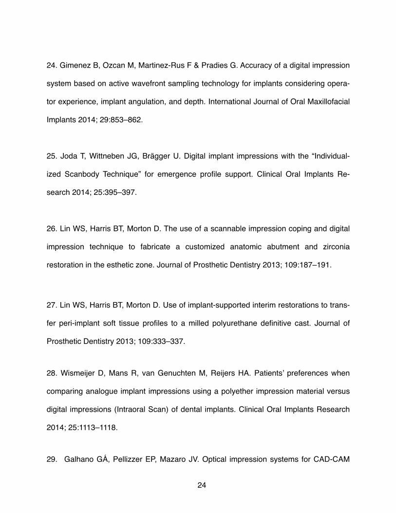
24. Gimenez B, Ozcan M, Martinez-Rus F & Pradies G. Accuracy of a digital impression
system based on active wavefront sampling technology for implants considering opera-
tor experience, implant angulation, and depth. International Journal of Oral Maxillofacial
Implants 2014; 29:853–862.
25. Joda T, Wittneben JG, Brägger U. Digital implant impressions with the “Individual-
ized Scanbody Technique” for emergence profile support. Clinical Oral Implants Re-
search 2014; 25:395–397.
26. Lin WS, Harris BT, Morton D. The use of a scannable impression coping and digital
impression technique to fabricate a customized anatomic abutment and zirconia
restoration in the esthetic zone. Journal of Prosthetic Dentistry 2013; 109:187–191.
27. Lin WS, Harris BT, Morton D. Use of implant-supported interim restorations to trans-
fer peri-implant soft tissue profiles to a milled polyurethane definitive cast. Journal of
Prosthetic Dentistry 2013; 109:333–337.
28. Wismeijer D, Mans R, van Genuchten M, Reijers HA. Patients’ preferences when
comparing analogue implant impressions using a polyether impression material versus
digital impressions (Intraoral Scan) of dental implants. Clinical Oral Implants Research
2014; 25:1113–1118.
29. Galhano GÁ, Pellizzer EP, Mazaro JV. Optical impression systems for CAD-CAM
�24

restorations. Journal of Craniofacial Surgery 2012; 23:e575–579.
30. Ramsey CD, Ritter RG. Utilization of digital technologies for fabrication of definitive
implant-supported restorations. Journal of Esthetic and Restorative Dentistry 2012;
24:299–308.
31. Lee SJ, Gallucci GO. Digital vs. conventional implant impressions: Efficiency outcomes. Clinical Oral Implants Research 2013; 24:111–115.
32. Moreno A, Giménez B, Ozcan M, Pradíes G. A clinical protocol for intraoral digital
impression of screw-retained CAD/CAM framework on multiple implants based on
wavefront sampling technology. Implant Dentistry 2013; 22:320–325.
33. Simon D. Ng, Keson B. Tan, K. H. Teoh, Ansgar C. Cheng, Jack I. Nicholls. Three-
Dimensional Accuracy of a Digitally Coded Abutment Implant Impresssion System. In-
ternational Journal of Oral Maxillofacial Implants 2014; 29:927-963.
34. The time efficiency of intraoral scanners: an in vitro comparative study.
Patzelt SB, Lamprinos C, Stampf S, Att W. (2014). Journal of the American Dental As-
sociation;145(6):542-51.
35. Klinberged IJ, Murray GM (1985) Design of superstructures for osseointegrated fix-
tures. Swedish Dental Journal 28:63–69.
�25

36. Guth, J.F., Keul, C., Stimmelmayr, M., Beuer, F. & Edelhoff, D. (2013) Accuracy of
digital models obtained by direct and indirect data capturing. Clinical Oral Investigations
17: 1201–1208.
�26

Appendix A: Tables.
Table 1: 3-D deviation values for all test groups.
Str Con Str Ture Def Str DW Nob Con Nob Ture Def Nob DW
Scan 1 14.008 14.878 28.730 15.507 25.883 30.171
Scan 2 11.745 16.923 17.292 17.709 21.913 13.894
Scan 3 31.838 15.976 16.328 24.734 25.659 14.101
Scan 4 14.139 25.698 24.015 12.532 28.442 45.501
Scan 5 25.927 22.947 14.522 22.357 23.218 22.975
Scan 6 50.576 18.549 36.685 15.760 25.275 22.415
Scan 7 34.836 19.632 18.032 16.583 26.138 17.324
Scan 8 40.562 19.579 44.560 15.893 22.717 20.157
Scan 9 44.970 15.007 37.380 15.828 25.325 15.276
Scan 10 9.958 17.591 24.540 15.935 25.843 15.892
�27

Table 2a:
RMS Error values for Straumann implant analogs (n=10 per group).
Table 2b:
RMS Error values for Nobel Biocare implant analogs (n=10 per group).
Groups that do not share a letter exhibited a statistically significant difference.
Median IQR p
Conventional 28.9 28.20.400
True Definition 18.1 4.7
Dental Wings 24.3 19.8
Median IQR p
Conventional 25.3 a 2.90.004
True Definition 18.7 ab 9.9
Dental Wings 15.9 b 3.2
�28

Appendix B: Figures.
Figure 1: The difference between Straumann and Nobel Biocare casts was significant
for Dental Wings digital impressions (p=0.023) but not for the other two impression
techniques (p=0.579 for conventional, p=0.853 for True Definition).
�29

Figure 2: (A) Clear acrylic master model for Nobel Biocare Conical Connection RP
Implant Analogs. (B) Stone Duplicate of the same model.
Figure 3 : Scans produced by different scanners for the Straumann Bone Level RC
Master model. (A) Activity 880 extra-oral scanner (B) Dental Wings intra-oral scanner (c)
True Definition intra-oral scanner.
�30

Figure 4: Geomagic 3D Comparison report of the Best Fit Alignment between Dental
Wings intra-oral scanner and the control master model.
�31


![[Our Redemption] Doctrines of Grace: Definitive Atonement](https://img.pdfslide.net/doc/110x75/61934b65b86f4e773a2b24f5/our-redemption-doctrines-of-grace-denitive-atonement.jpg)