Embed Size (px)
Citation preview
Nationaal Lucht- en RuimtevaartlaboratoriumNational Aerospace Laboratory NLR
DXXX-1A
Accurate Drag Computation for the DLR-F4 Wing/body Configuration Using
Multi-block, Structured-grid CFD Technology
O.J. Boelens, M. Laban, C.M. van Beek and R. van der leeden
National Aerospace Laboratory, NLR
Amsterdam, The netherlands

Nationaal Lucht- en RuimtevaartlaboratoriumNational Aerospace Laboratory NLR
DXXX-2A
Contents of Presentation
• CFD method
• Computational grid
• Test cases
• Grid convergence study
• Drag breakdown analysis
• Concluding remarks
Nationaal Lucht- en RuimtevaartlaboratoriumNational Aerospace Laboratory NLR
DXXX-3A
CFD Method
ENSOLV (part of NLR’s flow simulation system ENFLOW)
• time-dependent Reynolds-averaged Navier-Stokes equations
• cell-centred, central difference, finite volume scheme
• (pseudo) time integration by explicit Runge-Kutta scheme to obtain steady-state solution
• artificial dissipation (scalar and matrix) to prevent odd-even decoupling
• local time stepping, multi-grid and residual averaging to increase convergence
Nationaal Lucht- en RuimtevaartlaboratoriumNational Aerospace Laboratory NLR
DXXX-4A
CFD Method (Cont’d)
ENSOLV (part of NLR’s flow simulation system ENFLOW)
• basically original k-ω turbulence model as proposed by Wilcox
• slight modification by introduction of ‘cross diffusion’ term to eliminate free-stream dependency of ω
• solve τ=1/(ω+ω0) instead of ω, to remove singular behaviour of ω at solid walls
• production term in k-equation has been limited to prevent unphysical high values of k near stagnation point
Nationaal Lucht- en RuimtevaartlaboratoriumNational Aerospace Laboratory NLR
DXXX-5A
Computational Grid (‘NLR’ Grid)
• Structured multi-block grid generated with domain modeller ENDOMO and grid generator ENGRID (part of NLR’s flow simulation system ENFLOW)
• Overall topology is O-O-topology (cluster grid points around aerodynamic configuration)
• Three layers of blocks (one created by ‘off-set’ method, two created by ‘potential’ method)
• Final grid: – 104 blocks, – 2,840,576 grid cells, – approximately 30 grid points in boundary layer– y+ equal to one
Nationaal Lucht- en RuimtevaartlaboratoriumNational Aerospace Laboratory NLR
DXXX-6A
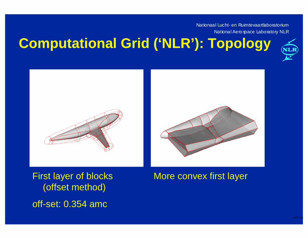
Computational Grid (‘NLR’): Topology
First layer of blocks (offset method)
off-set: 0.354 amc
More convex first layer
Nationaal Lucht- en RuimtevaartlaboratoriumNational Aerospace Laboratory NLR
DXXX-7A
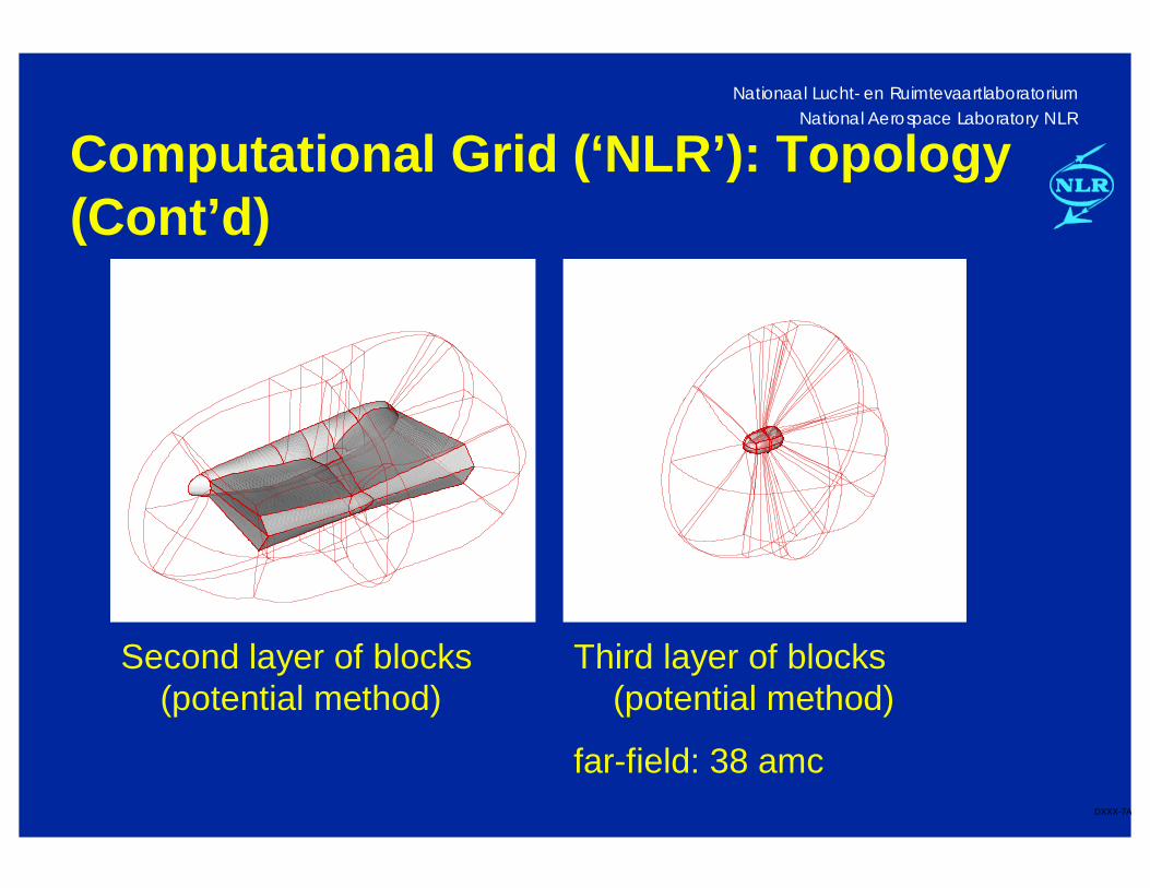
Computational Grid (‘NLR’): Topology (Cont’d)
Second layer of blocks (potential method)
Third layer of blocks (potential method)
far-field: 38 amc
Nationaal Lucht- en RuimtevaartlaboratoriumNational Aerospace Laboratory NLR
DXXX-8A
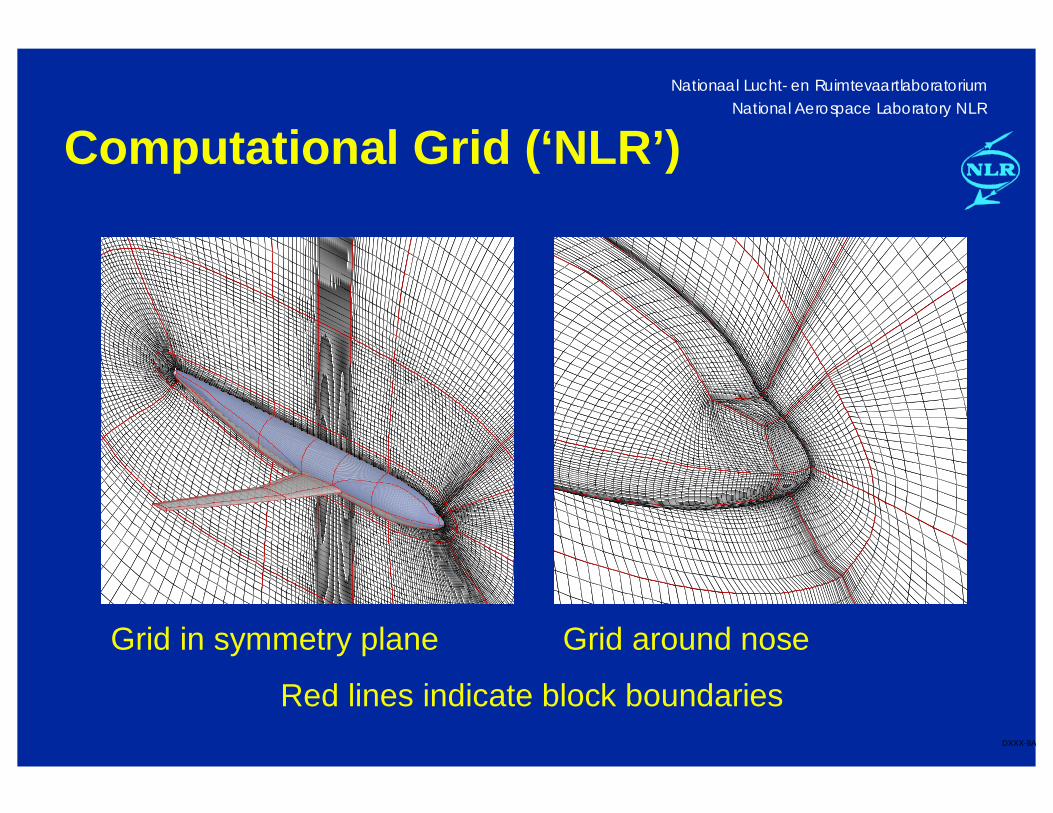
Computational Grid (‘NLR’)
Grid in symmetry plane Grid around nose
Red lines indicate block boundaries
Nationaal Lucht- en RuimtevaartlaboratoriumNational Aerospace Laboratory NLR
DXXX-9A
Test Cases
All test cases of AIAA Drag Prediction Workshop have been calculated using ‘NLR’ grid (test case one and three also using ‘DPW’ grid)
• Results are presented in paper
• Drag polar simulations (test case two) have been compared with NLR-HST experiment
• Data point α=0° and M∞=0.75 (test case two) used for further study:
– Grid convergence study
– Drag breakdown analysis
Nationaal Lucht- en RuimtevaartlaboratoriumNational Aerospace Laboratory NLR
DXXX-10A
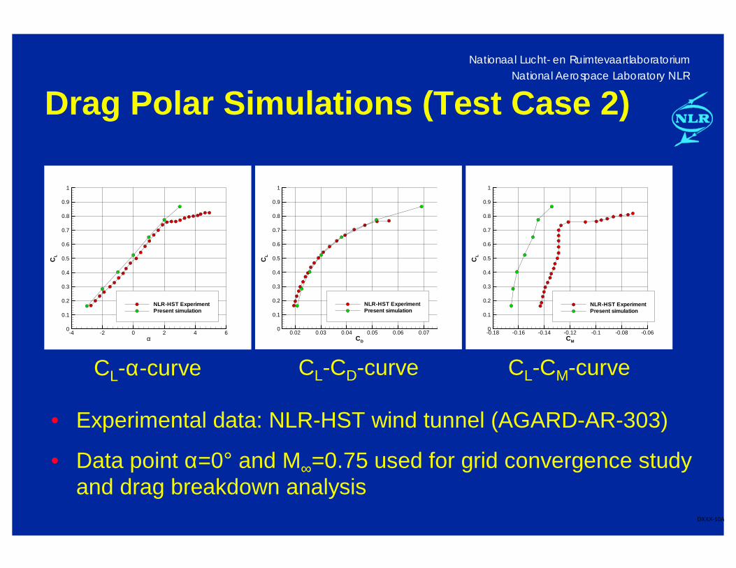
Drag Polar Simulations (Test Case 2)
CD
CL
0.02 0.03 0.04 0.05 0.06 0.070
0.1
0.2
0.3
0.4
0.5
0.6
0.7
0.8
0.9
1
NLR-HST ExperimentPresent simulation
CM
CL
-0.18 -0.16 -0.14 -0.12 -0.1 -0.08 -0.060
0.1
0.2
0.3
0.4
0.5
0.6
0.7
0.8
0.9
1
NLR-HST ExperimentPresent simulation
CL-α-curve CL-CD-curve CL-CM-curve
α
CL
-4 -2 0 2 4 60
0.1
0.2
0.3
0.4
0.5
0.6
0.7
0.8
0.9
1
NLR-HST ExperimentPresent simulation
• Experimental data: NLR-HST wind tunnel (AGARD-AR-303)
• Data point α=0° and M∞=0.75 used for grid convergence study and drag breakdown analysis
Nationaal Lucht- en RuimtevaartlaboratoriumNational Aerospace Laboratory NLR
DXXX-11A
Grid Convergence Study
Basic assumption for this ‘near-field’ extrapolation method
• Global accuracy of CFD solution on family of successively refined grid depends on relative mesh size h
Total drag coefficient on sequence of nested grids can be represented by:
• CD(h)=CD(h=0)+c1h+c2h2, or
• CD(h)=CD(h=0)+c3h3/2
CD(h=0) is the grid-converged drag coefficient, i.e drag coefficient for vanishing mesh width
Nationaal Lucht- en RuimtevaartlaboratoriumNational Aerospace Laboratory NLR
DXXX-12A
Grid Convergence Study (Cont’d)
Grids used in present study:
• h=1-grid,
• h=2-grid (deleting alternately grid points from h=1-grid),
• h=4-grid (deleting alternately grid points from h=2-grid), and
• h=4/3-grid (3/4 of number of grid points in each direction compared to h=1-grid)
Grids belong to same family, i.e. in terms of cell angle, cell aspect ratio and cell stretching
Nationaal Lucht- en RuimtevaartlaboratoriumNational Aerospace Laboratory NLR
DXXX-13A
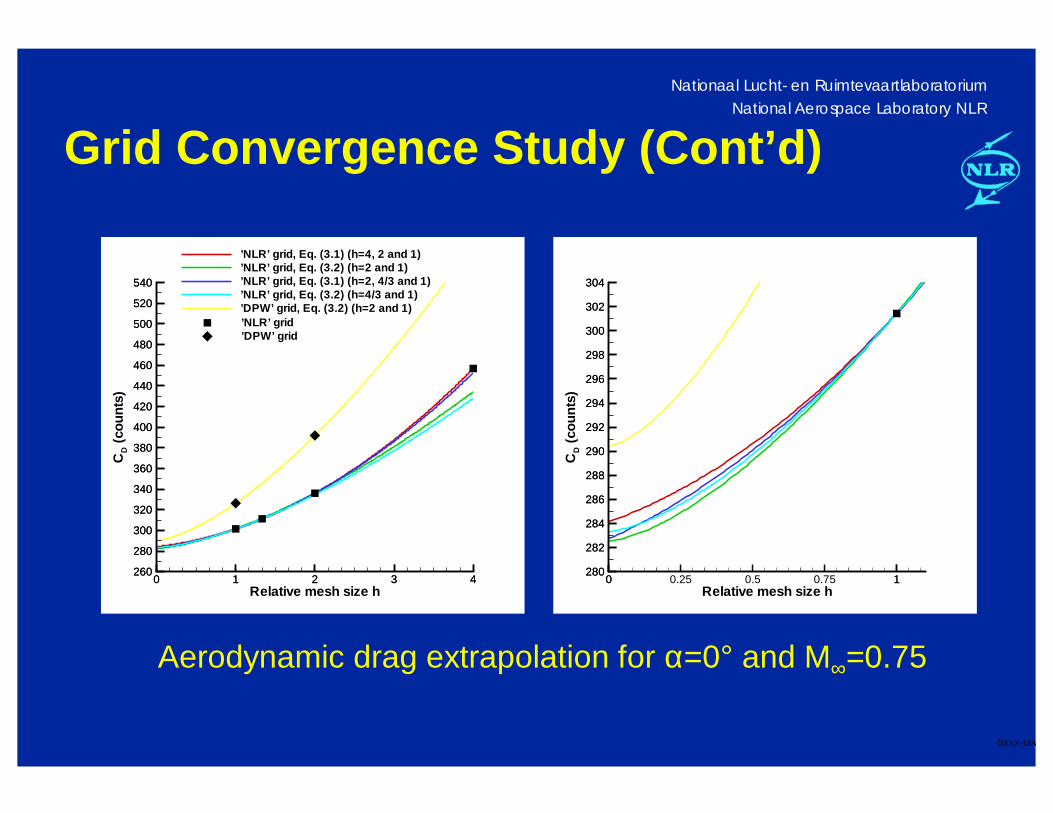
Grid Convergence Study (Cont’d)
Relative mesh size h
CD
(cou
nts)
0 1 2 3 4260
280
300
320
340
360
380
400
420
440
460
480
500
520
540
’NLR’ grid, Eq. (3.1) (h=4, 2 and 1)’NLR’ grid, Eq. (3.2) (h=2 and 1)’NLR’ grid, Eq. (3.1) (h=2, 4/3 and 1)’NLR’ grid, Eq. (3.2) (h=4/3 and 1)’DPW’ grid, Eq. (3.2) (h=2 and 1)
0 1 2 3 4260
280
300
320
340
360
380
400
420
440
460
480
500
520
540
’NLR’ grid’DPW’ grid
Relative mesh size h
CD
(cou
nts)
0 0.25 0.5 0.75 1280
282
284
286
288
290
292
294
296
298
300
302
304
0 1280
282
284
286
288
290
292
294
296
298
300
302
304
Aerodynamic drag extrapolation for α=0° and M∞=0.75
Nationaal Lucht- en RuimtevaartlaboratoriumNational Aerospace Laboratory NLR
DXXX-14A
Grid Convergence Study: Conclusions
‘NLR’ grid
• Difference between lowest (282.5 drag counts) and highest (284.1 drag counts) extrapolated value only 1.6 drag counts
‘DPW’ grid
• Extrapolated value using h=2-grid and h=1-grid 290.4 drag counts, i.e. approximately 7 drag counts higher than on ‘NLR’ grid
O-O-topology (‘NLR’ grid) well suited for ‘near-field’ extrapolation method, due to clustering of grid points around configuration
Nationaal Lucht- en RuimtevaartlaboratoriumNational Aerospace Laboratory NLR
DXXX-15A
Drag Breakdown Analysis
Decompose aerodynamic drag into its ‘physical’ components (‘far-field’ approach), i.e.• Vortex drag: due to trailing, streamwise vorticity
• Viscous drag: due to turbulent dissipation in boundary layers and wakes
• Wave drag: due to shock waves
In addition also spurious drag present (neither vortex drag, viscous drag or wave drag)
Combination of viscous drag, wave drag and spurious drag is referred to as entropy drag
Nationaal Lucht- en RuimtevaartlaboratoriumNational Aerospace Laboratory NLR
DXXX-16A
Drag Breakdown Analysis (Cont’d)
Calculation procedure is as follows:
1 Calculate vortex drag on ‘Trefftz plane’ downstream of aerodynamic configuration using vorticity-streamfunction formulation
2 Calculate entropy drag for all cells in box surrounding aerodynamic configuration
3 Assign entropy drag to either wave drag, viscous drag or spurious drag using automated zonal detection algorithm
Nationaal Lucht- en RuimtevaartlaboratoriumNational Aerospace Laboratory NLR
DXXX-17A
Drag Breakdown Analysis (Cont’d)
Automated zonal detection algorithm:
• Entropy drag is assigned to wave drag, if value of shock sensor (based on local velocity and pressure gradients) exceeds threshold
• Entropy drag is assigned to viscous drag, if value of viscous sensor (based on dissipation function associated with fluid viscosity) exceeds threshold
• Otherwise entropy drag is assigned to spurious drag
Spurious drag is not added to total drag balance
Nationaal Lucht- en RuimtevaartlaboratoriumNational Aerospace Laboratory NLR
DXXX-18A
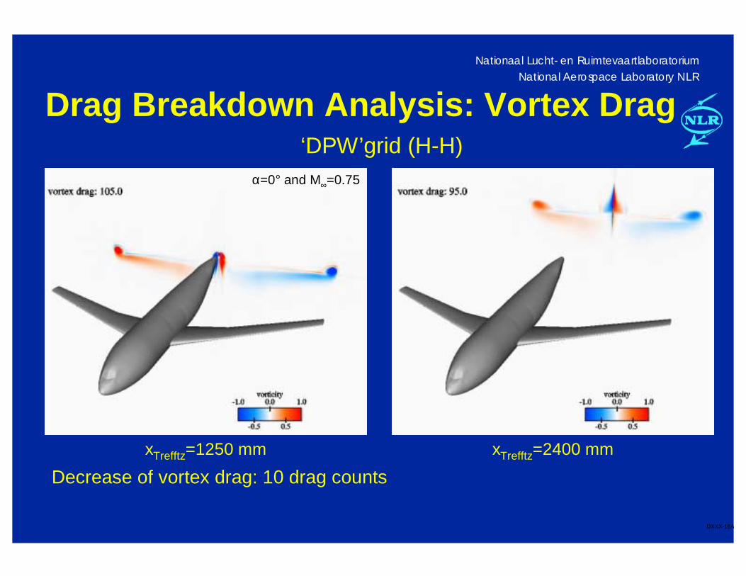
Drag Breakdown Analysis: Vortex Drag
xTrefftz=1250 mm xTrefftz=2400 mm
‘DPW’grid (H-H)
Decrease of vortex drag: 10 drag counts
α=0° and M∞=0.75
Nationaal Lucht- en RuimtevaartlaboratoriumNational Aerospace Laboratory NLR
DXXX-19A
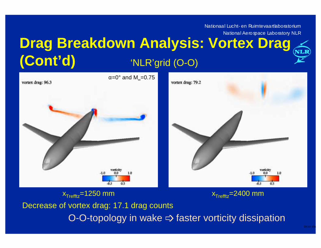
Drag Breakdown Analysis: Vortex Drag(Cont’d)
xTrefftz=1250 mm xTrefftz=2400 mm
‘NLR’grid (O-O)
Decrease of vortex drag: 17.1 drag counts
O-O-topology in wake ➩ faster vorticity dissipation
α=0° and M∞=0.75
Nationaal Lucht- en RuimtevaartlaboratoriumNational Aerospace Laboratory NLR
DXXX-20A
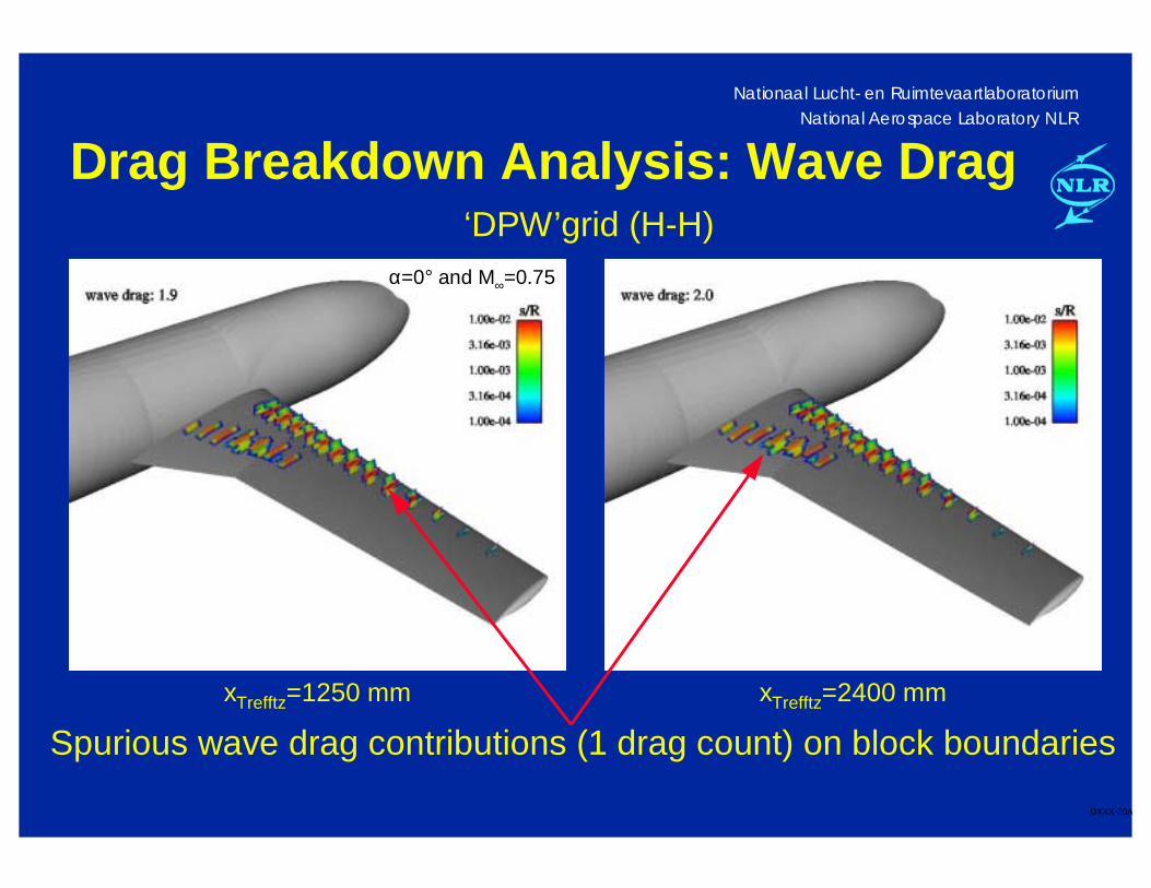
Drag Breakdown Analysis: Wave Drag
xTrefftz=1250 mm xTrefftz=2400 mm
‘DPW’grid (H-H)
Spurious wave drag contributions (1 drag count) on block boundaries
α=0° and M∞=0.75
Nationaal Lucht- en RuimtevaartlaboratoriumNational Aerospace Laboratory NLR
DXXX-21A
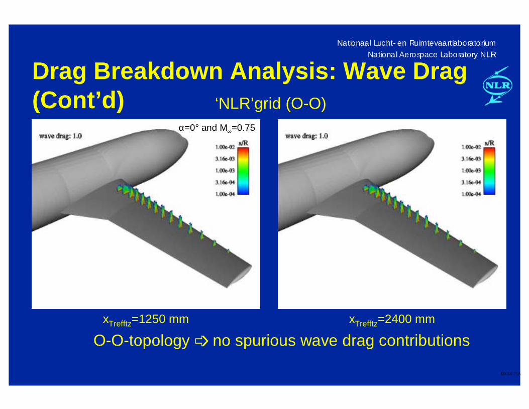
Drag Breakdown Analysis: Wave Drag(Cont’d)
xTrefftz=1250 mm xTrefftz=2400 mm
‘NLR’grid (O-O)
O-O-topology ➩ no spurious wave drag contributions
α=0° and M∞=0.75
Nationaal Lucht- en RuimtevaartlaboratoriumNational Aerospace Laboratory NLR
DXXX-22A
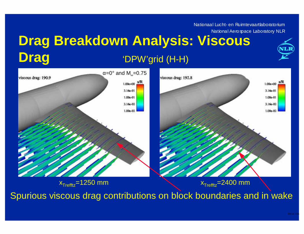
Drag Breakdown Analysis: Viscous Drag
xTrefftz=1250 mm xTrefftz=2400 mm
‘DPW’grid (H-H)
Spurious viscous drag contributions on block boundaries and in wake
α=0° and M∞=0.75
Nationaal Lucht- en RuimtevaartlaboratoriumNational Aerospace Laboratory NLR
DXXX-23A
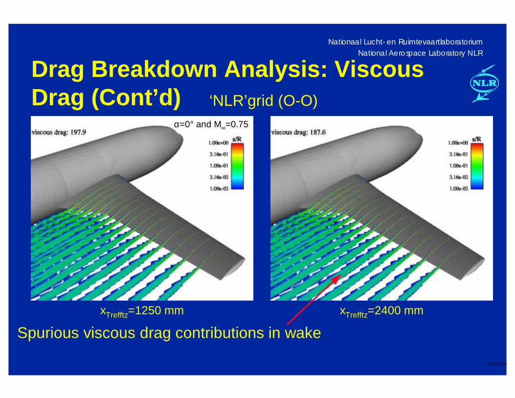
Drag Breakdown Analysis: Viscous Drag (Cont’d)
xTrefftz=1250 mm xTrefftz=2400 mm
‘NLR’grid (O-O)
Spurious viscous drag contributions in wake
α=0° and M∞=0.75
Nationaal Lucht- en RuimtevaartlaboratoriumNational Aerospace Laboratory NLR
DXXX-24A
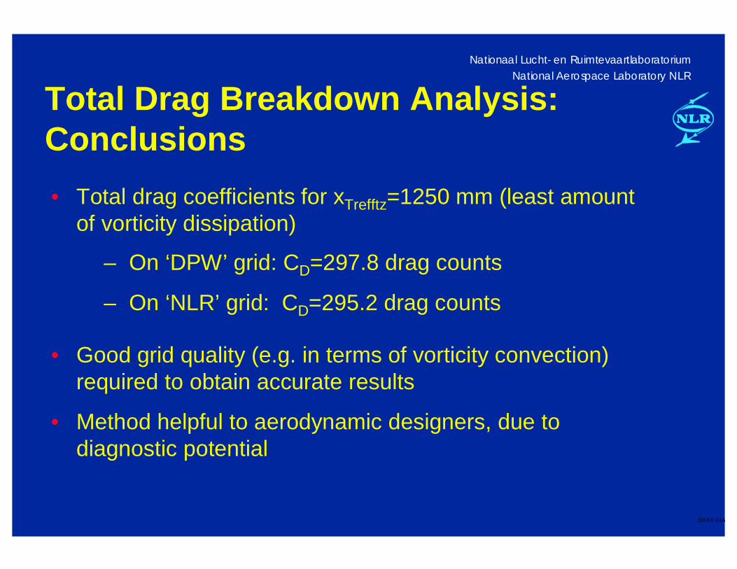
Total Drag Breakdown Analysis: Conclusions
– On ‘DPW’ grid: CD=297.8 drag counts
– On ‘NLR’ grid: CD=295.2 drag counts
• Total drag coefficients for xTrefftz=1250 mm (least amount of vorticity dissipation)
• Good grid quality (e.g. in terms of vorticity convection) required to obtain accurate results
• Method helpful to aerodynamic designers, due to diagnostic potential
Nationaal Lucht- en RuimtevaartlaboratoriumNational Aerospace Laboratory NLR
DXXX-25A
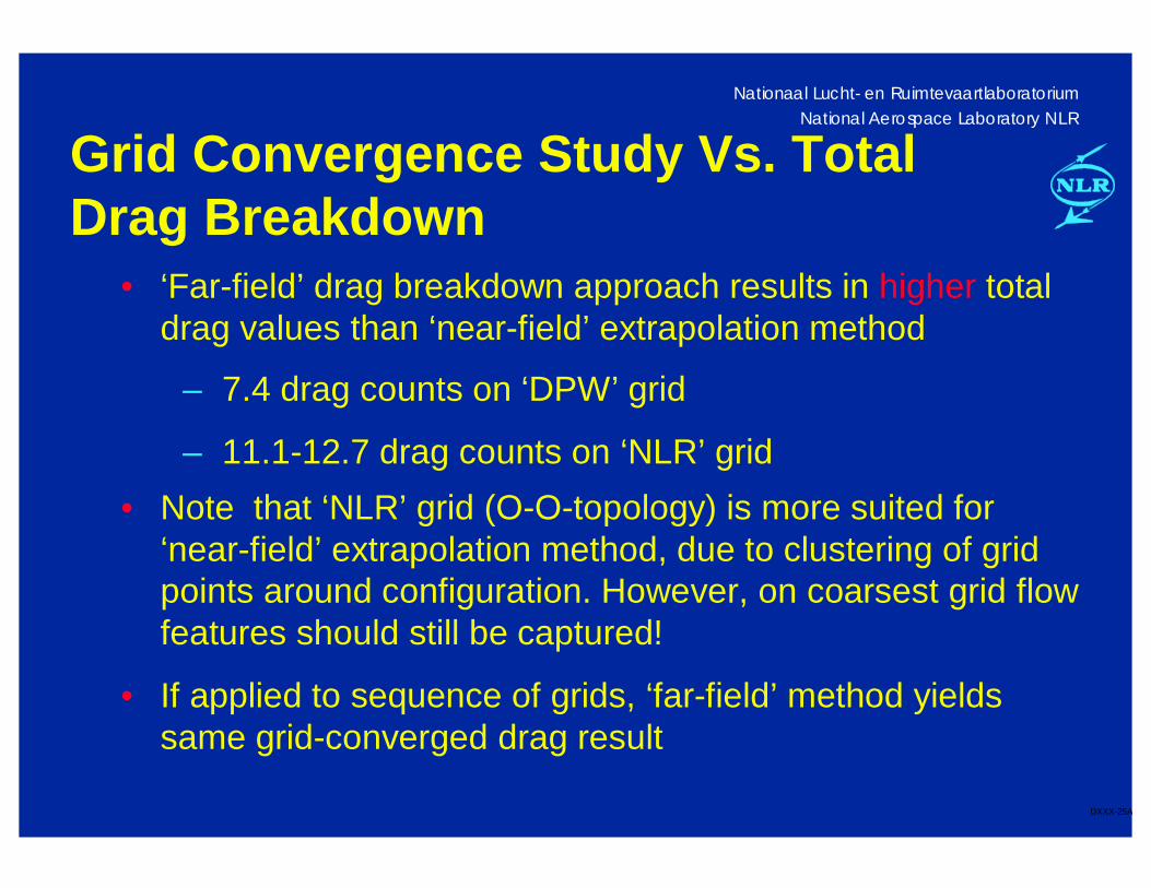
Grid Convergence Study Vs. Total Drag Breakdown
• ‘Far-field’ drag breakdown approach results in higher total drag values than ‘near-field’ extrapolation method
– 7.4 drag counts on ‘DPW’ grid
– 11.1-12.7 drag counts on ‘NLR’ grid
• Note that ‘NLR’ grid (O-O-topology) is more suited for ‘near-field’ extrapolation method, due to clustering of grid points around configuration. However, on coarsest grid flow features should still be captured!
• If applied to sequence of grids, ‘far-field’ method yields same grid-converged drag result
Nationaal Lucht- en RuimtevaartlaboratoriumNational Aerospace Laboratory NLR
DXXX-26A
Concluding Remarks
Two methods to obtain accurate drag values have been presented:
• ‘near-field’ extrapolation method
• ‘far-field’ drag breakdown method
Both methods require good grid quality to obtain accurate results:
• ‘near-field’ extrapolation method on coarsest grids
• ‘far-field’ drag breakdown method in wake region
‘Far-field’ drag breakdown method is helpful to aerodynamic designers, because its diagnostic potential