Embed Size (px)
Citation preview

1
EECE421 Power System Analysis
Chapter 4: Transmission Line Capacitance

Capacitance
G: ConductanceInsignificantIgnored in our discussion
2
C: CapacitanceCaused by the potential difference between the conductors(Charge) per (unit of potential difference)C = q / V or q = CV

Capacitance
3
Impact of Capacitance to CircuitCharging CurrentVarying voltage causes current to flow between two conductors
Impact of Charging Current

Impact of Capacitance
Line LengthVoltage
4

4.1 E-Field of a long Straight Conductor
5
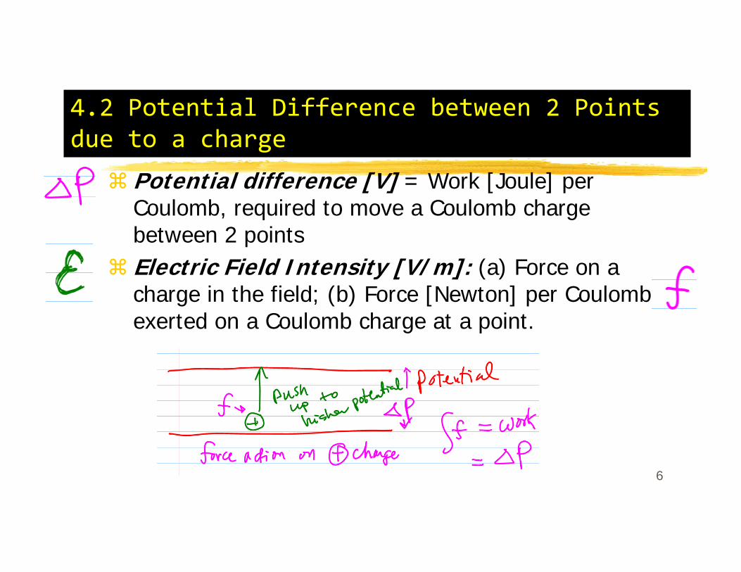
4.2 Potential Difference between 2 Points due to a charge
Potential difference [V] = Work [Joule] per Coulomb, required to move a Coulomb charge between 2 pointsElectric Field Intensity [V/m]: (a) Force on a charge in the field; (b) Force [Newton] per Coulomb, exerted on a Coulomb charge at a point.
6

Voltage Drop Between 2 Points
Equipotential LinesPotential Difference is Path IndependentEnergy used (expended) to do work voltage drop
7

Voltage Drop Between 2 PointsInstantaneous voltage drop
8

Capacitance of a 2-wire lineCapacitance between 2 conductors = “charge on the conductors per unit of potential difference between them”: C = q/V [F/m]
Voltage drop between two: due to qa and qb
9

Voltage Drop between 2 conductors
10
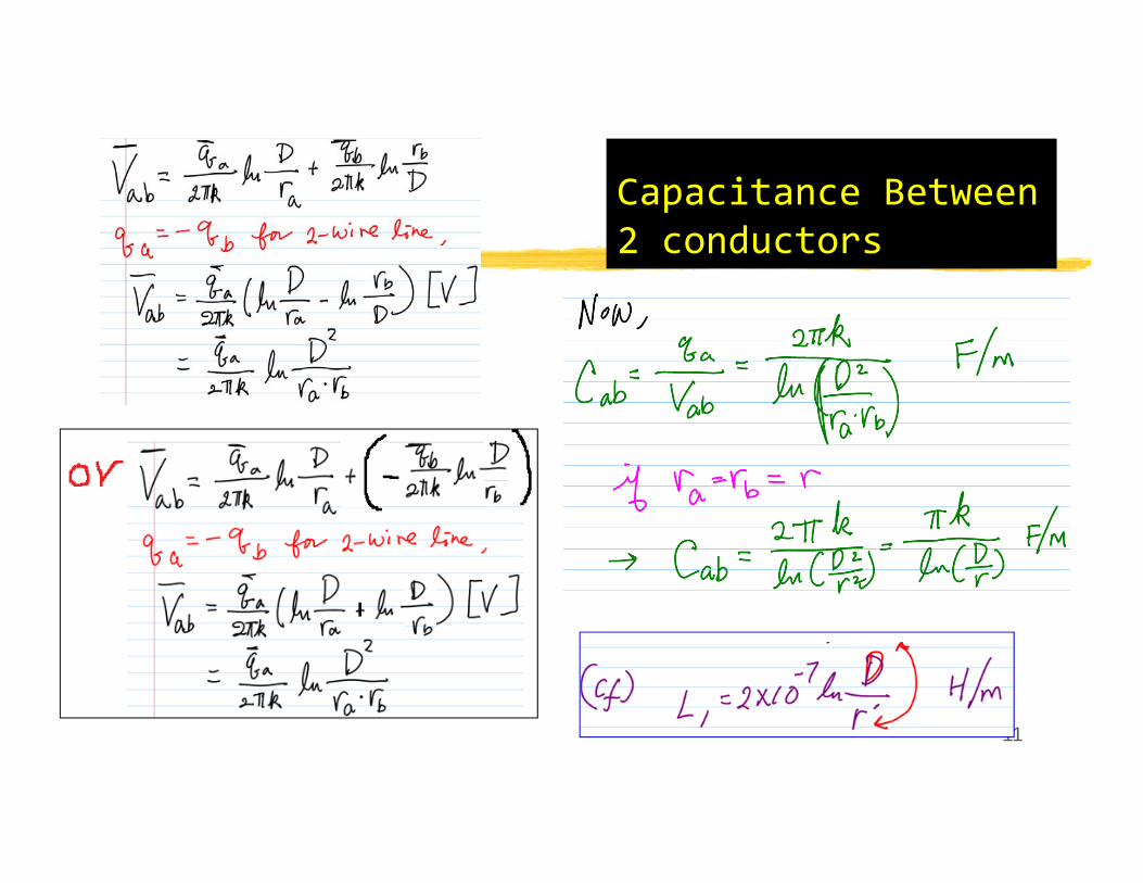
Capacitance Between 2 conductors
11

Capacitance Between 2 conductors
12
Polarity for ln (D/r) format for Vabwhen we have the third charge qc:
+: out from a+: in to b-: in to a-: Out from b

Class Activity
13

Class Activity
Recall
14

Capacitance between a conductor and the neutral
17

Capacitance between a conductor and the neutral
Capacitive Reactance to Neutral (Xc):
18

Capacitance between a conductor and the neutral
Separation of 2 terms
19
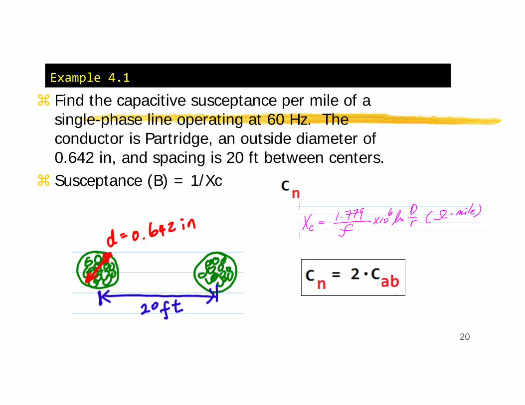
Example 4.1
Find the capacitive susceptance per mile of a single-phase line operating at 60 Hz. The conductor is Partridge, an outside diameter of 0.642 in, and spacing is 20 ft between centers.Susceptance (B) = 1/Xc
20

Example 4.1Find the capacitive susceptance per mile of a single-phase line operating at 60 Hz. The conductor is Partridge, an outside diameter of 0.642 in, and spacing is 20 ft between centers.
21

4.4 Capacitance of a 3-phase line with equivalent Spacing
22

4.4 Capacitance of a 3-phase line with equivalent Spacing
23

4.4 Capacitance of a 3-phase line with equivalent Spacing
24

25
Charging current between conductors

4.5 Capacitance of a 3-phase line with unsymmetrical spacing
26

4.5 Capacitance of a 3-phase line with unsymmetrical spacing
27
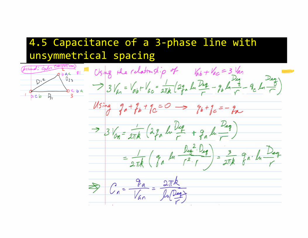
4.5 Capacitance of a 3-phase line with unsymmetrical spacing
28

Example 4.2For a single-circuit 3-phase line, (a) find the capacitance (C) and the capacitive reactance (Xc) for 1 mile of the line configured as below with ACSR Drake (diameter of each conductor is 1.108 inches). (b) If the length of the line is 175 miles and the normal operating voltage is 220 kV, find (b-1) the capacitive reactance to neutral for the entire length of the line, (b-2) the charging current per mile, and (b-3) the total charging Volt-Amperes (VA or Q) for the entire length of the line.
29

Example 4.2For a single-circuit 3-phase line, (a) find the capacitance (C) and the capacitive reactance (Xc) for 1 mile of the line configured as below with ACSR Drake (diameter of each conductor is 1.108 inches). (b) If the length of the line is 175 miles and the normal operating voltage is 220 kV, find (b-1) the capacitive reactance to neutral for the entire length of the line, (b-2) the charging current per mile, and (b-3) the total charging volt-Amperes (VA or Q) for the entire length of the line.
30

Example 4.2For a single-circuit 3-phase line, (a) find the capacitance (C) and the capacitive reactance (Xc) for 1 mile of the line configured as below with ACSR Drake (diameter of each conductor is 1.108 inches). (b) If the length of the line is 175 miles and the normal operating voltage is 220 kV, find (b-1) the capacitive reactance to neutral for the entire length of the line, (b-2) the charging current per mile, and (b-3) the total charging volt-ampere (VA or Q) for the entire length of the line.
31

Class Activity --- 3-Phase L and Y
32

4.6 Effect of Earth on the Capacitance of 3-phase lines
34

4.6 Effect of Earth on the Capacitance of 3-phase linesNormal E-Field Lines
35

4.6 Effect of Earth on the Capacitance of 3-phase linesActual E-Field Lines
36

4.6 Effect of Earth on the Capacitance of 3-phase lines
“Imaginary Conductor”: for the purpose of capacitance calculation (on the effect of Earth), the earth is replaced by a fictitious charged conductor below the surface of the earth by a distance equal to that of the overhead conductor above the earth.
37

3-Phase line and its image
38

3-Phase line and its image
39

3-Phase line and its image
40

3-Phase line and its image
41

3-Phase line and its image
42

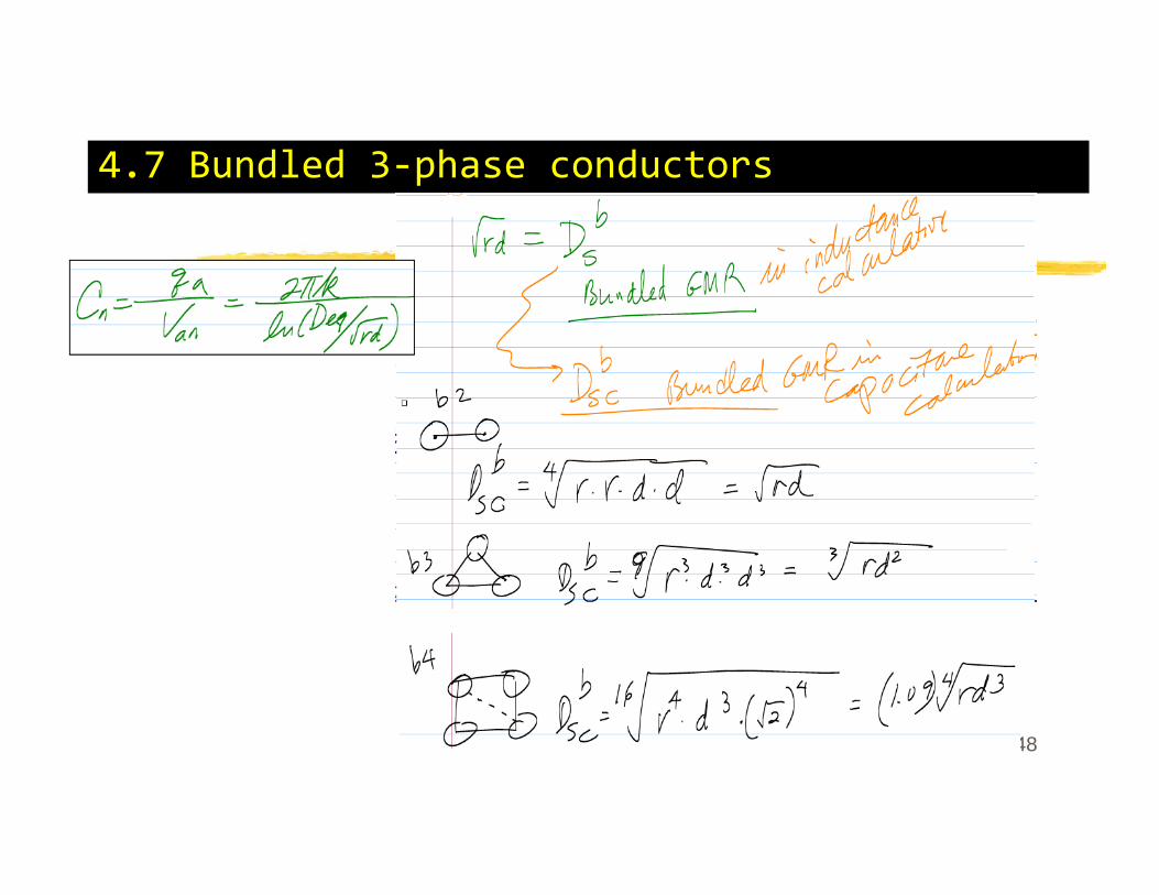
4.7 Bundled 3-phase conductors
43
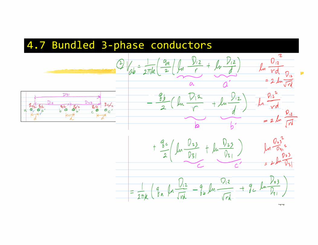
4.7 Bundled 3-phase conductors
44

4.7 Bundled 3-phase conductors
45

4.7 Bundled 3-phase conductors
46

4.7 Bundled 3-phase conductors
47
4.7 Bundled 3-phase conductors
48

Example 4.3
Find the capacitive reactance to neutral of the line show below. The outside diameter of each conductor is 1.382 inches, and the distance of each bundled conductor is 45 cm.
49

Example 4.3
Find the capacitive reactance to neutral of the line show below. The outside diameter of each conductor is 1.382 inches, and the distance of each bundled conductor is 45 cm.
50
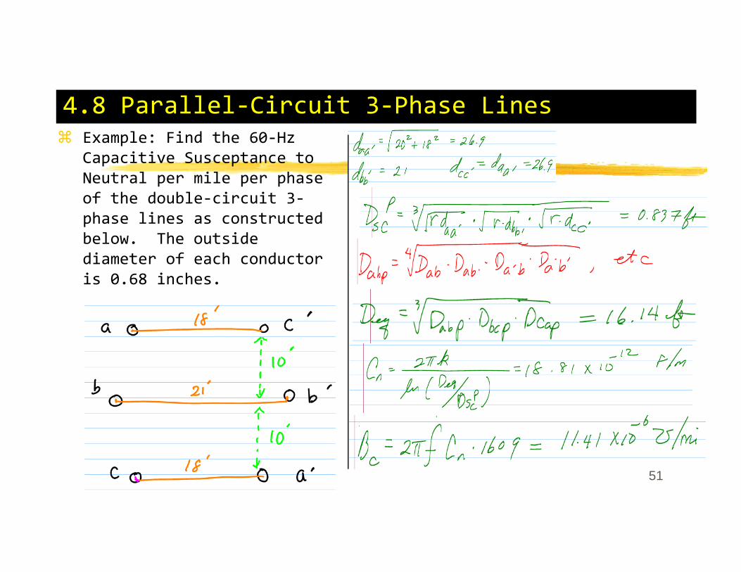
4.8 Parallel-Circuit 3-Phase LinesExample: Find the 60-Hz Capacitive Susceptance to Neutral per mile per phase of the double-circuit 3-phase lines as constructed below. The outside diameter of each conductor is 0.68 inches.
51

4.8 Parallel-Circuit 3-Phase Lines.
52
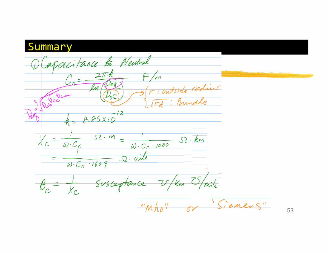
Summary.
53