Embed Size (px)
Citation preview
Achieving (and maintaining)electrical connection tightness
Reliability depends upon the integrity between conductors
By Richard L. Nailen, P.E., EA Engineering Editor
CAN A CONNECTION BE TOO TIGHT? YES ANDno. Supposedly, someone once asked AbrahamLincoln, “How long should a man’s legs be?” His
answer: “Long enough to reach from his body to theground.”
Along that same line, one might ask, “How tight shouldan electrical connection be?” The simple answer is, “Tightenough to carry the maximum circuit current forever with-out overheating, arcing, or significant voltage drop.”Unfortunately, that answer is no more useful than Lincoln’s.
Insofar as the contact surfaces between two conductorsare concerned, “the tighter the better.” The joint may in-volve two flat surfaces (such as terminal lugs—see Figures1 and 2), or a wire and a pressure plate of some sort, as in a“screw lug” (Figures 1 and 3).
Both types may take many forms (Figure 4). The subjecthere is not crimp connectors, or spring assemblies (such asfuse clips), or joints involving brazing or soldering betweenconductors, but terminations held together by threaded fas-teners. At one extreme is the bus bar assembly, usuallyclamped together by two or more large bolts and nuts (cov-ered nearly two decades ago in “What makes bolted con-nections tight enough?,” EA March 1988).
At the other extreme is the small screw terminal on abranch circuit device such as a lampholder (Figure 5). Inbetween are compression connectors involving sockets orsaddles in which conductors are squeezed by tightening ascrew or bolt (Figure 1).
Problems with rough surfacesAlthough flat mating surfaces may appear smooth, elec-
trical contact is actually made through numerous tiny
Figure 1. Two basic types of bolted connection, in which fastener tighten-ing torque should be carefully controlled. At (a), fasteners clamp the con-necting wires directly. At (b), the tightening torque acts instead on con-ducting surfaces of the hardware and terminal lug.
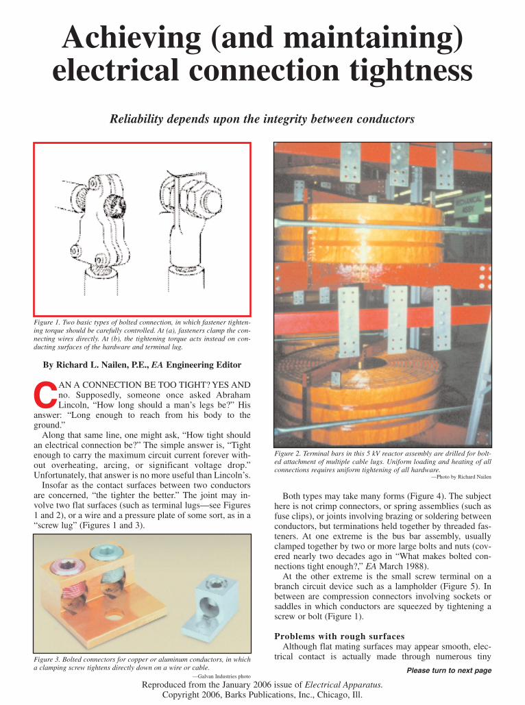
Figure 2. Terminal bars in this 5 kV reactor assembly are drilled for bolt-ed attachment of multiple cable lugs. Uniform loading and heating of allconnections requires uniform tightening of all hardware.
—Photo by Richard Nailen
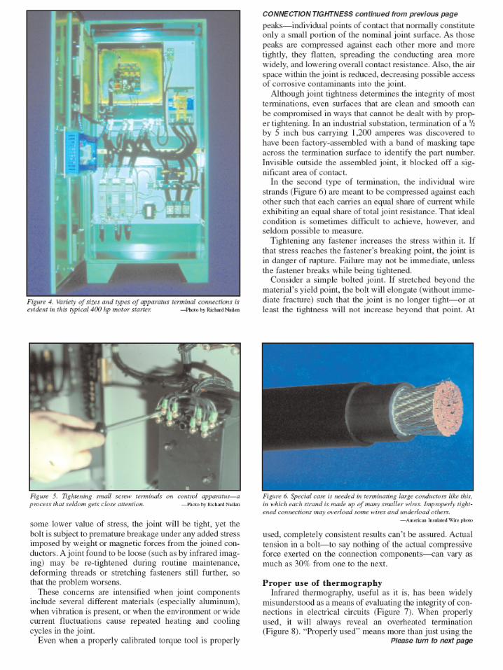
Figure 3. Bolted connectors for copper or aluminum conductors, in whicha clamping screw tightens directly down on a wire or cable.
—Galvan Industries photoPlease turn to next page
Reproduced from the January 2006 issue of Electrical Apparatus.Copyright 2006, Barks Publications, Inc., Chicago, Ill.
imaging equipment within its limitations, and properlyinterpreting the readings. For example, in a three-phase cir-cuit, how much difference is allowable between the temper-ature of one phase and that of the other two? Is total tem-perature the important criterion, or should it be the riseabove ambient?
“Proper use” also means not jumping to conclusions as tothe nature of the problem. Overheating may have more thanone cause. All too often, maintenance workers haveassumed that any hot connection is “loose.” Their responseis to re-tighten it. “Loose connections” do develop higherresistance and are likely to get hotter than they should. Asindicated by Paragraph. 110.14 of the National ElectricalCode, connections to “equipment terminations” are toinvolve conductors that won’t be hotter than either 65°C or75°C (depending upon current and conductor size), regard-less of the temperature rating of the conductor insulation. Ahigher conductor operating temperature will add heat toconductor terminations.
Uncontrolled heating and cooling cycles, together withcorrosion in a hostile environment, can accelerate deteriora-tion in the joint. Even when that’s not the case, re-tighten-ing may still be ineffective because the problem lies in thenature of the connection rather than its tightness. If onecomponent is a compression lug, for example, the boltedconnection between lug and terminal may be tight, but thewire or cable crimp within the lug was not properly made orhas deteriorated in service. Wire strands may break or bepulled loose.
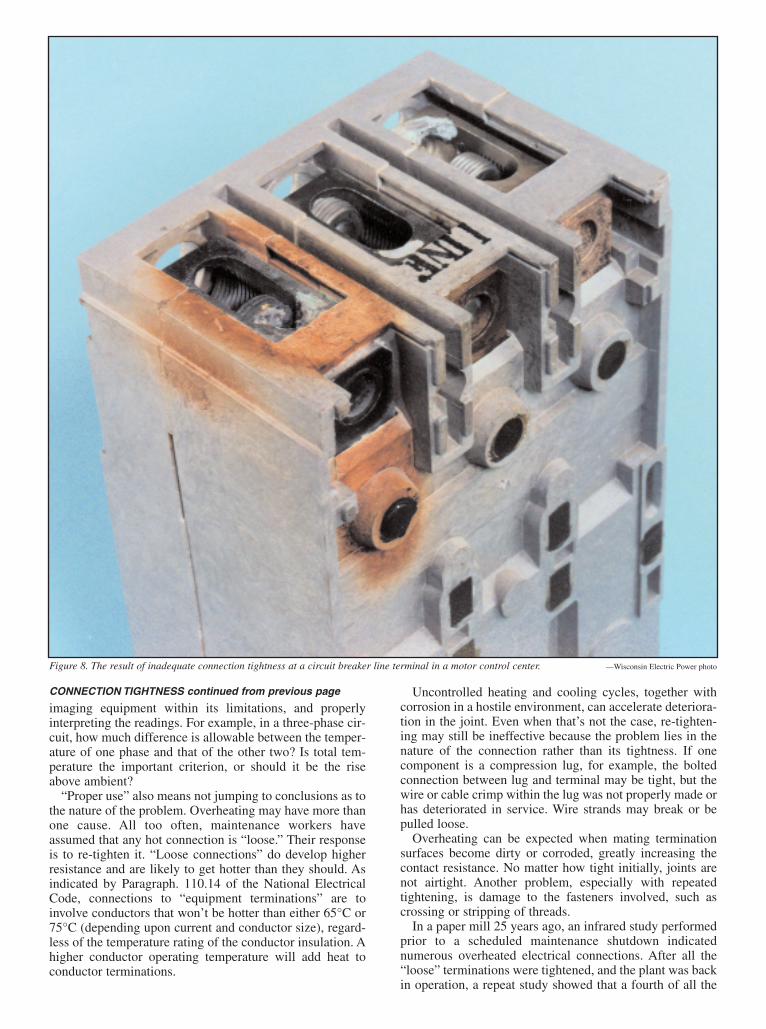
Overheating can be expected when mating terminationsurfaces become dirty or corroded, greatly increasing thecontact resistance. No matter how tight initially, joints arenot airtight. Another problem, especially with repeatedtightening, is damage to the fasteners involved, such ascrossing or stripping of threads.
In a paper mill 25 years ago, an infrared study performedprior to a scheduled maintenance shutdown indicatednumerous overheated electrical connections. After all the“loose” terminations were tightened, and the plant was backin operation, a repeat study showed that a fourth of all the
Figure 8. The result of inadequate connection tightness at a circuit breaker line terminal in a motor control center. —Wisconsin Electric Power photo
CONNECTION TIGHTNESS continued from previous page

problems observed in the first round were still present.Some had gotten worse.
Examination of the repair records showed that when sus-pect connections were taken apart, cleaned, and put backtogether, 92% of them exhibited acceptable temperature.But when a connection was only re-tightened, only one infive showed improvement.
What the National Electrical Code saysWhat does the National Electrical Code say about tight-
ening terminations? Turning to Section 110.14 in the 1984edition of the Code, we find the first appearance of therequirement that “devices such as pressure terminal or pres-sure splicing connectors . . . shall be suitable for the mater-ial of the conductor and shall be properly installed and used.. . .” A Fine Print Note adds this: “Many terminations andequipment are [sic] marked with a tightening torque.”
Then and since, 110.14(A) adds that “Connections ofconductors to terminal parts shall ensure a thoroughly goodconnection without damaging the conductors. . . .” (How“thoroughly good” differs from “good” has not beenexplained.)
The wording of the Code is usually taken to imply thatterminations are to be tightened to the value (if any) that ismarked on the equipment. But that is implicit rather thanexplicit. The practice has become increasingly common.Back in the spring of 1985, a leading electrical trade publi-cation ran this headline over its lead editorial: “Torquingelectrical terminals—soon, it will be mandatory!” For fiveyears, the magazine had been advocating the practice for“all current-carrying electrical terminals and joints,” toachieve “a precisely determined value of contact pressure.”Either “inadequate” or “excessive” tightening was said toaccount for most electrical failures.
Why “mandatory”? In 1984 (the year of the NEC revi-sion), Underwriters Laboratories publications began requir-ing circuit breakers and enclosed switches to be markedwith a tightening torque value “for all wire connectorsintended for use with field wiring.” In Section 110.3(B), theNEC had already required that “Listed or labeled equip-ment shall be used or installed in accordance with anyinstructions included in the listing or labeling.” Thus, theUL changes meant that installers had to comply with thetorque markings provided in accordance with the UL list-ing.
Why, then, isn’t the practice universal today? First,because the UL and NEC requirements apply only to “fieldwiring”—to connections made when listed apparatus isinstalled. No such requirements apply to internal connec-tions—such as bus bar joints within switchgear, tap chang-er connections within transformers or regulators, terminalboards inside control centers or electronic apparatus, ormany other factory assemblies. Secondly, the initial ULstipulations dealt only with breakers and switches, not fuseblocks, dry-type transformers, reactors, motor starters, rec-tifiers, battery chargers, etc.
In any event, specifying (and using) a torque value doesnot necessarily result in a “precisely determined” contactpressure. How much contact pressure exists within any jointdepends upon the condition and nature of the contact sur-faces as much as upon the force exerted by one or moretightened fasteners. No universal practice governs the size,shape, or stiffness of a terminal lug on a conductor basedjust on the wire gauge size. Furthermore, different conduc-tor sizes, and therefore different lug sizes, may be attached
to the same apparatus terminal (such as a motor lead).Hence, when bolts are tightened to a specific pound-inch
value of torque, the installer can have no idea what the con-tact pressure is within the joint. It can hardly be considered“precisely determined.”
Questions unanswered by technologyDespite those yawning loopholes, the use of torque mark-
ings—and the use of torque wrenches and screwdrivers infield wiring—has increased. Electricians, electrical inspec-tors, and maintenance technicians continue to question thepractice, though, not because they don’t recognize the valueof torque control, but because of these questions for whichthe technology has not provided firm answers:
1. All physical limits, such as machining dimensions,operating temperatures, and vibration levels, must involvetolerances. When tightening torque is listed or marked as“25 lb-in,” for example, what’s the tolerance? Is 25 a lowerlimit (25 minus zero), an upper limit (25 plus zero), or nei-ther? What plus/minus variation is allowable?
2. If the correct tightness is present at installation, and (bywhatever means) the joint is later found to be “loose,”which of the following actions should be taken?
a. Re-tighten the joint to the original or listed value(which is of no help unless that original value is known).
b. Disassemble the joint and re-assemble using spring
Figure 7. Infrared surveillance can be useful for electrical connections ofall types and sizes, but the results must be interpreted carefully, especiallywhen dealing with a variety of operating conditions and current levels.
—Pomona Electronics photo
Please turn to next page

washers, a sealant, or some kind of locking device.3. How accurate is a torque tool? How can its calibration
be checked, and how often should recalibration be done?
Solid versus stranded wireWhen the joint is tightened by “squeezing” a wire, an
ongoing debate among electrical installers involves the rel-ative merits of solid and stranded conductors, particularly inlarger sizes such as No. 10 and above. Because it is muchstiffer in handling, solid wire can be easier to push throughsome raceways (although harder to remove). On the otherhand, the greater flexibility of stranded wire renders it eas-ier to place inside cabinets or junction boxes where space islimited. The NEC requires most conductors in raceways tobe stranded in sizes 8 and larger.
Some electricians contend that compression terminationsfor stranded wire tend to exhibit higher resistance becausethe innermost strands are compressed less tightly than thoseon the periphery. However, product listings and manufac-turer recommendations generally sanction the use of eithersolid or stranded conductors.
What about wires of the same gauge but two differentstrandings? For the added flexibility needed in close quar-ters within rotating machinery, motor and generator leadcables use finer stranding—many more strands of smallerwire—than the power cable used in utility work or com-mercial building wiring. For the same total cross-sectionalarea (and therefore the same resistance and ampacity), thefiner the stranding, the larger the physical O.D. of the con-ductor. The difference is not great. For example, comparingFigure 9(a) with Figure 9(b), for a No. 6 gauge wire, theouter diameters are 0.186 and 0.210 inch respectively.
Hence, when extra-flexible “locomotive cable” or “weld-ing cable” is used to achieve maximum flexibility in wiring,properly fitting the conductor to terminal assemblies can bedifficult. “Making it fit” by trimming strands—either fromthe conductor periphery, or (to make it less noticeable) fromthe interior, is unacceptable.
So, what are electricians saying and doing about theissue? In the trade, comments like these are not uncommon:
“I’ve been hand-tightening 500 mcm for years and neverhad any problems.”
“I suggest to re-tighten aluminum connections every fiveyears.”
“The foreman of this job asked why I use a torquewrench. I replied, ‘Don’t you?’ He said no.”
“I was taught never to re-torque a connection.”
“Whenever I finish a job, the inspector comes along, andgives all the connections another half turn or so, no matterhow tight they were to begin with.”
“I was always taught that the tighter you make a connec-tion, the better. . . . I have split neutral bars from tightening. . . stripped out 600 kcmil split bolts. . . . I have always donethis in the belief that I was doing a good job; I thought theresistance falls as the connections get tighter.”
Others have said—whether facetiously or not—that theywere taught to “tighten it until it breaks and then back off aquarter turn,” or “torque it down till it strips then back it upa half-turn.”
The right way to tighten a connectionWhat, then, is the “right way”? These appear to be the
most useful guidelines:1. When a termination is given a tightening torque limit
by the manufacturer, work to that limit, using a properlycalibrated torque tool (wrench or screwdriver). Avoid con-fusing “pound-inches” with “pound-feet,” and distinguishproperly between English and metric units.
2. Subsequently, when infrared scanning or any otherform of surveillance indicates that a termination may haveloosened, do not routinely re-tighten to the original torquelevel. Instead, take the connection apart. If one joint mem-ber is wire or cable, cut that back a sufficient length to re-make the joint with undisturbed conductors; check the con-dition of other joint components for mechanical integrityand cleanliness; then re-assemble the joint, applying theproper torque as if it were new work. In the process, checkfasteners carefully for signs of such damage as strippedthreads. n
Figure 9. Although of the same wire gauge and ampacity as the conven-tional power cable at left, the more finely stranded wire at right necessar-ily has a slightly larger outside diameter. Hence, the same size terminalconnector may not be a proper fit on both conductors.
CONNECTION TIGHTNESS continued from previous page
Each of these motor lead connections in a European “phase segregated”terminal box includes two clamping fasteners similar to those in Figure1(a). —Photo by Richard Nailen