Embed Size (px)
Citation preview
Pave Israel 96
Summary
ACHIEVING EXCELLENCE - LESSONS
FROM RECENT PORT AND AIRPORT
PROJECTS IN AMERICA
D.R. Smith Interlocking Concrete Pavement Institute
Sterling, Virginia, USA
Design, construction, and maintenance aspects are reviewed for four airport and three port projects. The text incorporates information from technical papers, project specifications, designers, contractors, users, and involvement by the author on the projects. All were constructed between 1990 and 1994. All but one project is located in the US.A It was designed and built by American engineers and contractors. The reasons for selecting interlocking concrete pavement are given. The projects demonstrate structural, maintenance, and life-cycle cost advantages of i2.terlocking concrete pavements. Lessons from each are given on design, specification or construction. Most of these concern construction details. These lessons can be used to make more excellent projects in the future.
Airports
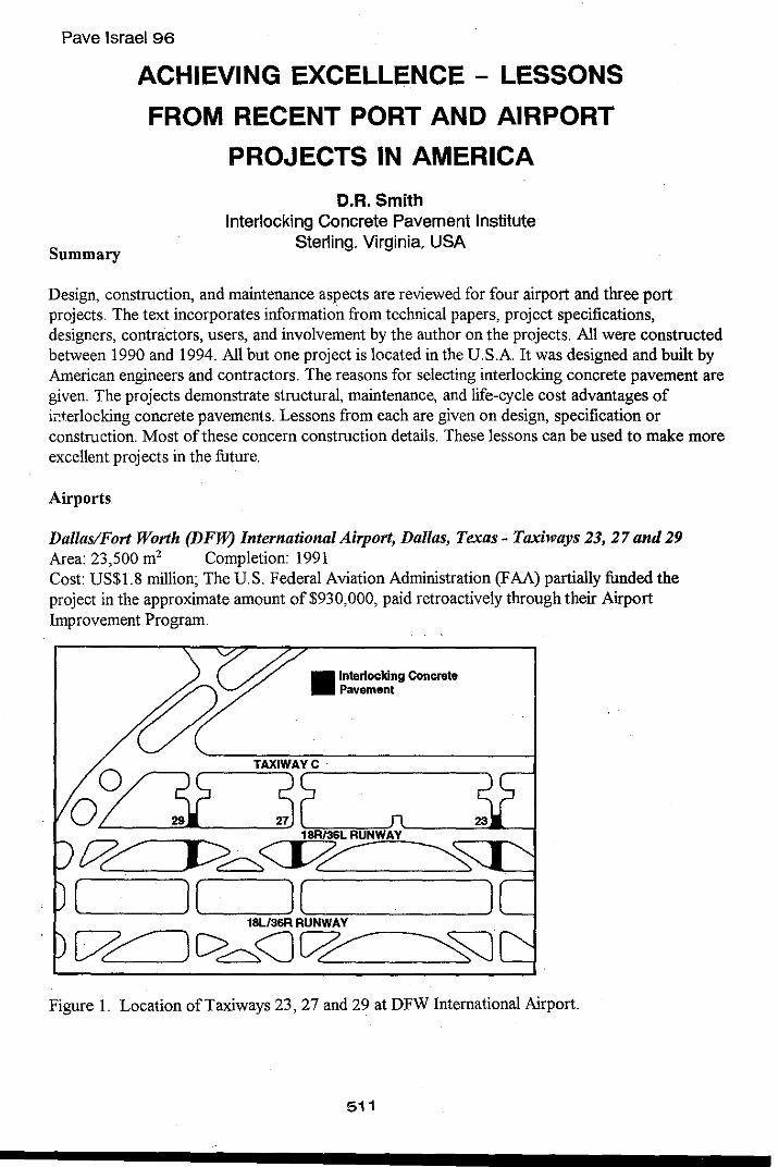
Dallas/Fort Worth (DFW) International Airport, Dallas, Texas - Taxiways 23, 27 and 29 Area: 23,500 m2 Completion: 1991 Cost: US$1.8 million; The US. Federal Aviation Administration (FAA) partially funded the project in the approximate amount of $930,000, paid retroactively through their Airport Improvement Program.
~ ____ -=~~~III=-_~_n~_e:m_~_e_~_~g_Co __ n_~_ew ______ --4
TAXIWAyrC ______________ "
or?( ~ },18R=/3""6L"R"'U"'NiUW.:.AY''-----'''O-'---/
[7/ J>~<J7~ ~ [::-:-====:::::::)( ](~========~ ~==l
18L/36R RUNWAY
[7~C>~<JW:
Figure 1. Location of Taxiways 23, 27 and 29 at DFW International Airport.
511
Rationale Construction of cross taxiways adjacent to 18R136L runway at DFW airport required night time closure. Runway closure during construction had significant impact on air traffic, causing delays in both air and ground operations. Portland cement concrete (PCC) pavement normally used at DFW would require closures unacceptable to the airport and airlines. Interlocking concrete pavements were selected because they could reduce nightly closures from 14 to 12 hours over a 114-night construction period (1)(2)(3). DFW Airport represents the first use of interlocking concrete pavements in an airport application in the U.S.A.
According to the Air Transport Association (AT A), this saved an estimated $37,130 per day in delays to the airlines, or $4,232,820 over the 114-night construction. The ATA calculations made in September 1989 are low, because they did not account for fuel cost increases in 1990 when the taxiways opened (4).
Concrete pavers had an additional safety benefit. When the cloud ceiling dropped below 325 m, airport operations required that all construction cease and the closed 18R136L runway be opened for traffic. Unexpected stoppage of construction required removal of all workers, material and equipment within 30 minutes after notification from airport operations. This time constraint was met with interlocking concrete pavement. In contrast, construction ofPCC pavement for high speed exits further down the runway involved two hours to clear equipment and personnel.
Structural Design The basis of structural design was the US. Federal Aviation Administration (FAA) flexible pavement design method in FAA Advisory Circular 15015320-6 "Airport Pavement Design and Evaluation"(5). The FAA concurred with replacing 100 mrn thick asphalt normally used in their flexible pavement design method with 80 mrn thick pavers and 40 mrn of bedding sand in the structural design method.
Pavement Cross Section Joint sand stabilizer: Glyciboxy propyl silane. 80 mm thick rectangular concrete pavers placed in herringbone pattern: Average 28 day minimum compressive strength: 55 Mpa; average tensile splitting strength 4.5 MPa (6); average maximum absorption 5% with no individual unit greater than 6%; freeze-thaw durability: Canadian Standards Association (CSA) A231.2-M85 freeze-thaw deicing salt test (7). Joint widths were controlled by specifYing the cumulative dimensions of 20 pavers laid end to end and side to side. 25 mm of bedding sand: silica sand from 10 mm to 150 !1m. Bedding sand degradation was evaluated using the Lilley-Dowson Sand Degradation test method (8). Joint sand: sand blasting sand with from 1.18 mrn to 150 !1m. 685 mm cement treated base (CTB): 5% cement content, seven day strength of 5.2 Mpa. Subgrade: Lime-fly ash injected 1.2 m to 1.5 m below finished subgrade, achieving a minimum of 7% CBR. Injection was done prior to excavation and placement of the base and pavers. CBRs as high as 28% were attained. Native soil subgrade: Highly expansive clay with a Plasticity Index of39, 2%-5% CBR, with areas as low as 1.5% CBR.
512
Interlocking concrete pavement was installed manually. The pavement was proof roller with a static drum roller upon completion of paving.
Loads Design loads included commercial aircraft ranging from 182 kN to 2,680 kN with 15% of the aircraft over 1,334 kN. The pavement was designed for a 20 year life. Loads measured from traffic monitoring in 1994 were converted to an estimated equivalent of MD-ll annual departures. From 1991 to 1994 they are 7,029 for Taxiway 23,832 for Taxiway 27, and 938 for Taxiway 29 (10). A MD-ll has a gross load of2,680 kN and a wheel load in the range of225 kN.
Performance In 1990, prior to opening ofthe pavement DFW staff measured elevations over a 3 m grid. Skid resistance measurements taken with Saab skid tester ranged between 0.63 and 0.69 with 0.65 as an average. This was a very good result for new pavement. Structural capacity was measured using a falling weight deflectometer (FWD) to establish base line data for future evaluations. Pavement Consultants, Inc. of Seattle, Washington, a engineering consulting company, conducted the FWD tests.
An evaluation of the taxiways was conducted in 1995 by Harding Lawson Associates of Reno, Nevada, a engineering consulting company. This included measurement of elevations, a pavement distress covering 50% of Taxiway 27, and 25% of23 and 29. The evaluation included structural analysis using a FWD. The information below is excerpted from their report (10).
Taxiways 23 and 27 had isolated areas with 25 mm to 50 mm of heaving. Taxiway 29 had an area raise as high as 125 mm. Elevations were expected to change due to the expansive soils. The excess heaving on Taxiway 29, however, was likely due to lack of subgrade stabilization and/or weakened CTB. FWD data verified a weakened pavement base and subbase in the area of the heaving.
The most common distresses were loss of bedding sand along the edges of the pavement adjacent to concrete shoulders and to a lesser extent at the joints along the PCC pavement. Loss of sand at the shoulders was from heaving of the clay soils under them, since they were not stabilized with lime-flyash. In all the taxiway interiors, loss of bedding sand and depressed pavers mirrored paving lane joints in the CTB. No rutting, creep or swell was observed on the taxiways. In some areas of the taxiways, the joints have lost sand to a depth of 20-30 mm.
Measurements were taken in 1994 with a Dynatest FWD. The load plate was 450 mm in diameter. Loads applied were 133 kN, 178 kN and 244 kN. Deflections were measured at 0 mm, 305 mm, 610 mrn, 915 mrn, 1,220 mm, 1,525 mm, and 1,830 mm from the load.
Back calculations were matched to measured deflections. The three modeled layers were the pavers and bedding sand, the CTB, and the stabilized and natural sub grades. Table 1 below presents the average values for the measurements taken in 1991 and 1994.
513
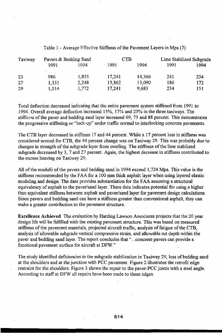
Table 1 - Average Effective Stiffness of the Pavement Layers in Mpa (7)
Taxiway Pavers & Bedding Sand CTB Lime Stabilized Subgrade 1991 1994 1991 1994 1991 1994
23 986 1,855 17,241 14,366 241 234 27 1,331 2,248 15,862 13,090 186 172 29 1,014 1,772 17,241 9,683 234 151
Total deflection decreased indicating that the entire pavement system stiffened from 1991 to 1994. Overall average deflection increased 15%, 17% and 23% in the three taxiways. The stiffu~,s ofthe paver and bedding sand layer increased 69, 75 and 88 percent. This demonstrates the progressive stiffening or "lock -up" under traffic normal to interlocking concrete pavements.
The CTB layer decreased in stiffuess 17 and 44 percent. While a 17 percent loss in stiffuess was considered normal for CTB, the 44 percent change was on Taxiway 29. This was probably due to changes in strength of the sub grade layer from swelling. The stiffness of the lime stabilized sub grade decreased by 3, 7 and 27 percent. Again, the highest decrease in stiffuess contributed to the excess heaving on Taxiway 29.
All of the modulii of the pavers and bedding sand in 1994 exceed 1,724 Mpa. This value is the stiffuess recommended by the FAA for a 100 mm thick asphalt layer when using layered elastic modeling and design. The data provides substantiation for the FAA assuming a structural equivalency of asphalt to the paver/sand layer. There data indicates potential for using a higher than t<quivalent stiffuess between asphalt and paver/sand layer for pavement design calculations. Since pavers and bedding sand can have a stiffuess greater than conventional asphalt, they can make a greater contribution to the pavement structure. .
Excellence Achieved The evaluation by Harding Lawson Associates projects that the 20 year design life will be fulfilled with the existing pavement structure. This was based on measured stiffuess of the pavement materials, projected aircrafl traffic, analysis offatigue of the CTB, analysis of allowable subgrade vertical compressive strain, and allowable rut depth within the paver and bedding sand layer. The report concludes that " ... concrete pavers can provide a functional pavement surface for aircraft at DFW."
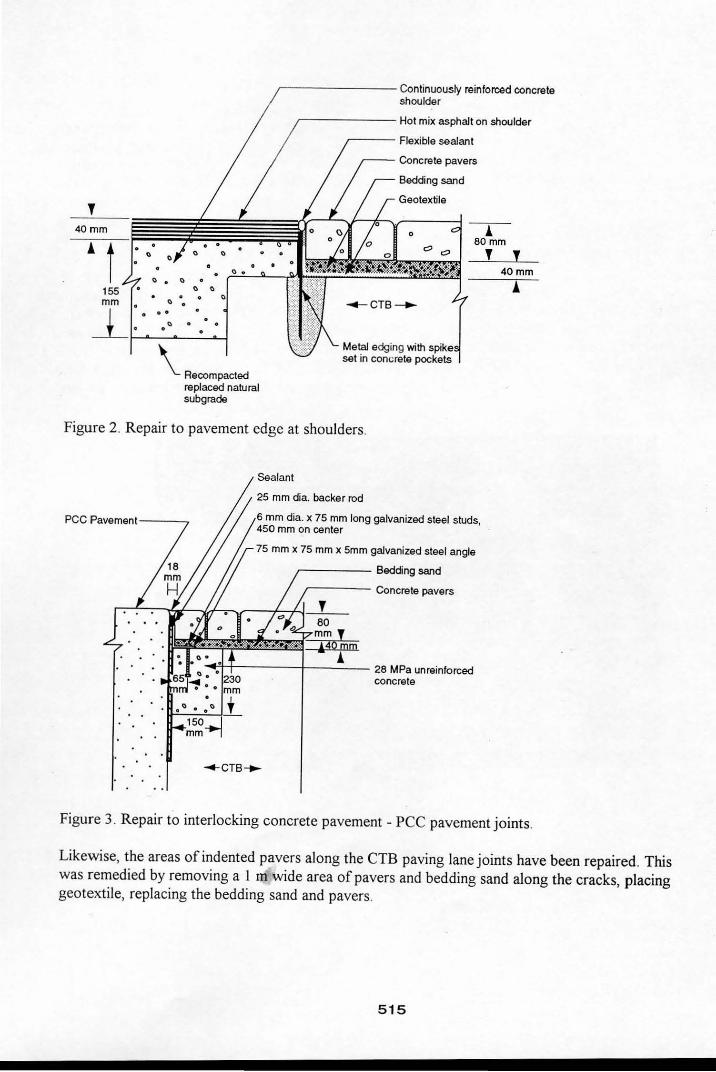
The study identified deficiencies in the subgrade stabilization in Taxiway 29, loss of bedding sand at the shoulders and at the junction with PCC pavement. Figure 2 illustrates the retrofit edge restraint for the shoulders. Figure 3 shows the repair to the paver-PCC joints with a steel angle. According to staff at DFW all repairs have been made to these edges.
514
T 40mm
" " ". "
" .. . "
\ Recompacted replaced natural subgrade
r-- - --- -- Continuously reinforced concrete shoulder
r---- -- Hot mix asphalt on shoulder
~--- Flexible sealant
! 80 rnm
T T 40mm
Figure 2. Repair to pavement edge at shoulders.
pee Pavement---~
Sealant
25 mm dia. backer rod
6 mm dia. x 75 mm long galvanized steel studs, 450 mm on center
75 mm x 75 rnm x 5mm galvanized steel angle
~---- Bedding sand
,----- Concrete pavers
T 80
! ....,'I-1~-----l---=--- 28 MPa unreinforced
mm ,
440jnm
concrete
_eTS_
Figure 3. Repair to interlocking concrete pavement - PCC pavement joints.
Likewise, the areas of indented pavers along the CTB paving lane joints have been repaired. This was remedied by removing a I m wide area of pavers and bedding sand along the cracks, placing geotextile, replacing the bedding sand and pavers.
515
The loss of joint sand "fJl ,~drs to have stopped, and does not detract structurally or functipnally. In the author' s opinion, I, .,s was due to using an inferior joi nt stabilization material. Urethane was originally specified for tli , DFW project but substituted with a silane product to save money. According to staff at DFW, the joints will be refilled in the next year and re-sealed.
The use of concrete pavers saved millions of dollars in delays and provided a serviceable pavement for DFW airport . The retrofitting demonstrates the commitment by DFW to providing an excellent airfield pavement.
Lessons Consider using a geotextil e over CTB, especially if cracks will form in paving lane joints or on the surface as it cures. The fabric can prevent migration of bedding sand into surface cracks that are a normal part of CTB curing. The edge restraint curb or shoulder must rest on the same base as the pavement so that movement is the same between the pavement and shoulder. Use of a urethane sealer could have assured higher joint sand stabili ty. In retrospect, the paver installation contractor noted that mechanical installation would have accelerated completion of the project even further.
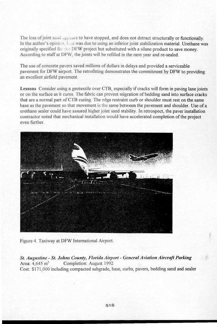
Figure 4. Taxiway at DFW International Airport.
St A ugustine - St Johns County, Florida Airport - General Aviation Aircraft Parking Area: 4,645 m' Completion: August 1992 Cost: $171,000 including compacted subgrade, base, curbs, pavers, bedding sand and sealer
516
Rationale The Florida Department of Transportation (FDOT) Aviation Office investigated alternative pavements on which to park aircraft weighing between 266 kN and 444 kN. PCC pavements required to support aircraft are more expensive than asphalt pavements, making them unaffordable at many airports, especially non-commercial ones. This was a FDOT demonstration project, and the first general aviation airfield in Florida with interlocking concrete pavement (11).
Asphalt pavements are subject to degradation from aviation fuel spills and static indentation from tires. Furthermore, some aircraft pilots sample and check fuel for the presence of water. After sampling from the tanks, the fuel is discarded on the pavement, eroding asphalt before it evaporates. Since coal tar seal coatings are not immune to fuel spills, concrete pavers appeared to be a more durable and cost-competitive solution.
Structural Design FAA.
Loads Parking for maximum 444 kN loads from general aviation aircraft and business jets. 5-6,000 departures annually.
Pavement Cross Section Joint sand stabilizer: Glyciboxy propyl silane. 80 mm thick rectangular concrete pavers conforming to ASTM C 936 (12), placed in a herringbone pattern. 25 mm of bedding sand: 9.5 mm to 150 11m. Joint sand: 2.36 mm to 75 11m. Base: 150 mm FDOT limerock Subbase: 100% to 300 mm depth sandy soil, CBR 15% Native soil subgrade: sand Interlocking concrete pavement was installed with mechanical equipment.
Performance The use of the pavement varies from none to practically full of aircraft for special events. The performance of the pavement has been excellent as no maintenance has been required. Unlike asphalt pavements and seal coats with a similar exposure, the concrete pavers at St. Augustine airport have required no maintenance.
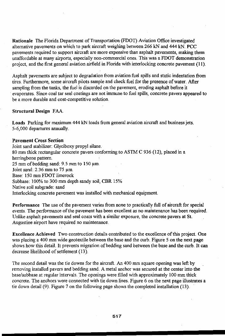
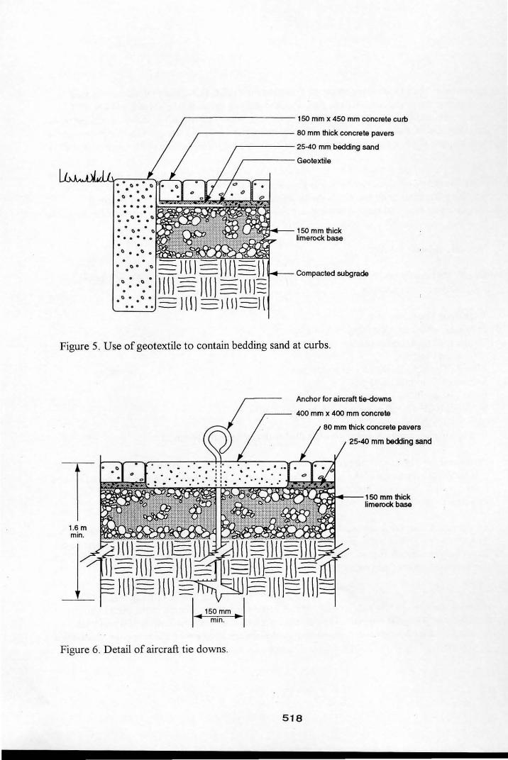
Excellence Achieved Two construction details contributed to the excellence of this project. One was placing a 400 mm wide geotextile between the base and the curb. Figure 5 on the next page shows how this detail. It prevents migration of bedding sand between the base and the curb. It can decrease likelihood of settlement (13).
The second detail was the tie downs for the aircraft. An 400 mm square opening was left by removing installed pavers and bedding sand. A metal anchor was secured at the center into the base/subbase at regular intervals. The openings were filled with approximately 100 mm thick concrete. The anchors were connected with tie down lines. Figure 6 on the next page illustrates a tie down detail (9). Figure 7 on the following page shows the completed installation (13).
517
,---------- 150 mm x 450 mm concrete curb
,--------- 80 mm thick concrete pavers
,-----25-40 mm bedding sand
,-----Geotextile
150 mm thick limerock base
=1(\1= .:- .:: mr TIIT mJ t+- Compacted subgrade
.' .. ': =)( \ 1 = I (II-ll Figure 5. Use of geotextile to contain bedding sand at curbs.
1.6 m min.
150 rnm .. mm . .,
Figure 6. Detail of aircraft tie downs.
Anchor for aircraft tie-downs
,--- 400 mm x 400 mm concrete
518
80 mm thick concrete pavers
25·40 mm bedding sand
...l'l~-- '50 mm thick limerock base
Figure 7. Aircraft tie downs in use.
Owen Roberts International Airport, Grand Cayman Island, British West Indies Area: ·9,807 m2 Completion: 1992 Cost: $4.16 million total project
Figure 8. Apron at Grand Cayman International Airport.
519
Rationale Grand Cayman airport required major pavement rehabilitation due to a steady increase of departures, and by heavier aircraft. While the condition of the existing asphalt aircraft parking apron was very good, it specifically required strengthening. The existing apron was subject to eroding from fuel spills. The apron also required an increase in slope to facilitate surface drainage.
The existing pavement structure was 100 mm to 125 mm of asphalt over 300 mm of aggregate base. The apron area was overlaid with 75 mm to 125 mm of asphalt for strengthening. Pavers and bedding sand were overlaid on top of this pavement. This saved approximately $500,000 compared to using conventional PCC pavement. The concrete pavers enabled one parking position at a time on the apron to be renovated and immediately opened. Therefore, there were no interruptions in scheduled flight operations during the course of the construction.
Loads 2,000 annual departures per parking position (5 positions total). Design aircraft was a B-727. Typical traffic included 727s, 757s, and 737s.
Structural Design FAA.
Pavement Cross Sectiou Ioint sand stabilizer: Glyciboxy propyl silane, silicone resin. 80 mm thick rectangular concrete pavers conforming to ASTM C 936, placed in herringbone pattern. 25 mm of bedding sand: 10 mm to 75 flm. Bedding sand degradation was evaluated using the Lilley-Dowson Sand Degradation test method. Sand was locally quarried. Ioint sand: 1.18 mm to 75 flm. Base: 175 mm to 225 mm asphalt, including existing and overlaid asphalt. Subbase: 300 mm existing crushed aggregate base. Native soil subgrade: coral sand, CBR 20%. Interlocking concrete pavement was installed with mechanical equipment. The pavement was proof rolled with a 30 ton rubber tired roller upon completion of paving.
Performance The pavement has performed well. The pavers in areas of jet blast have lost 20-30 mm of joint sand and have been refilled. This would likely not have been the case if urethane joint stabilizing material was specified. A few of the pavers under the aircraft main gear have cracked in one or two parking positions. Small depressions have appeared in the pavement under the main gear. This is likely due to marginal bedding sand. The cracked units have been replaced, and the units lifted and brought to former elevations.
Since Grand Cayman Island is coral, the quality oflocal aggregates is at best marginal. The bedding sand did not meet the specified limits for degradation due to its soft nature. This was recognized at the outset of the project. The trade-off was that minor repairs of pavers from time to time would be less costly than importing extremely hard bedding sand at initial construction.
520
Prior to construction, power back aircraft departures, i.e., using full power on engine thrust reversers, was a normal procedure for one airline. The other carriers used tugs for pushing back departing aircraft, or occasionally powered forward ifthere was space available on the apron. For safety reasons, the airport asked the one air carrier to change operations to push back aircraft with a tug or power forward. The request was met without objections, since there are no jetways, and sufficient room for aircraft to move forward and turn to depart under partial power.
Excellence Achieved The edge details to restrain the pavers and bedding sand were developed specifically for contact against asphalt. Figure 7 shows this construction detail. A key to the success of this detail is paving the asphalt 60 cm past the location of the steel edge. The compacted asphalt is then saw cut back to the location of the steel edge restraint. Cutting and removing the excess asphalt ensures the highest compacted material adjacent to the concrete pavers and steel edge restraint.
An FAll., approved design manual published by the Interlocking Concrete Pavement Institute, Airfield Pavement Design with Concrete Pavers, was written by the engineer from the experience with this project and by researching others. The guide includes design, specifications, construction details, life-cycle costs and maintenance guidelines (13)(14). While not specifically a problem in this project, geotextile covered drain holes at the lowest elevations are recommended for future projects. These are recommended in the design manual.
r--- 2 lifts of FAA P-401 asphalt
Joint sealant
13 mm dia. x 300 mm long galvanized steel spikes 600 mm on center
75 n:tm x 75 mm x 5 mm galvanized steel angle
80 mm thick concrete pavers
25 mm - 40 mm bedding sand
-.j- Asphalt
Figure 9. Edge restraint detail for overlay/inlay.
Lessons learned Use of urethane in the joints would have provided greater joint sand stability.
Long Island McArthur Airport, Islip, New York Area: 1,341 m2 Completion: 1994 Cost: $136,458, The FAA partially funded the project in the approximate amount of$122,800 paid through their Airport Improvement Program.
521
Rationale Static indentation of existing asphalt pavement at two aircraft parking positions necessitated pavement rehabilitation. The indentations were so severe that aircraft were difficult to push back with a tug. Rather than replace the parking areas with 350 mm ofPCC, an inlay of concrete pavers and bedding sand were tried (15) . This reduced gate closure time by about 10 days since there was no waiting for PCC pavement to cure.
Loads 737, MD-80 aircraft weighing approximately 620 kN arriving 4-5 times per day per gate.
Structural Design FAA
Pavement Section Joint sand stabilizer: Urethane. 80 mm thick rectangular concrete pavers conforming to ASTM C 936, placed in herringbone pattern. Freeze-thaw durability: CSA A231 .2-M85 freeze-thaw deicing salt test. 25-40 mm of bedding sand : 10 mm to 75 11m. Bedding sand degradation was evaluated using the Lilley-Dowson Sand Degradation test method and sand passed tests. Sand was locally quarried. Joint sand: 1.18 mm sieve to 75 11m. Base: Existing asphalt 325 mm thick milled down to 200 mm to 210 mm thick to accommodate inlay of pavers and bedding sand. Geotextile over the asphalt base. Subbase : 175 mm existing crushed aggregate base. Native soil subgrade: not known. Interlocking concrete pavement was installed manually. Pavement was proof rolled upon completion with a 10 ton rubber tired roller.
~. ,.,.
" . ,
Figure 10. Applying urethane sealer. Figure II . MD-80 wheels on the pavement.
522
Performance Movement in the pavers under the main gear and between the gear occurred soon after opening to jet aircraft. Depressions of about 15 mm formed under the main gear tires and pavers cracked under them. The movement of the pavers caused the joint stabilization material to break and allow excess ingress of water into the bedding sand. Lack of drainage of water in the bedding sand further exacerbated the movement of the pavers when loaded.
The pavers and bedding sand were removed under the main gear to check for rutting of the asphalt. There was none observed. Deformation, however, may have been occurring without rutting. Movement of the pavers is likely to be influenced by the saturated bedding sand. Particle shape of the sand may have been a factor.
An attempt to remedy the lack of drainage was made by placing five 100 mm diameter drain holes in the lowest elevations of each parking position. Urethane sealer was reapplied. This apparently haS not allowed drainage of the bedding sand layer. Water fills the sand and causes the pavers to move under loads. In contrast to these distresses, snow plowing of the concrete pavers has presented no problems.
Lessons There were conditions interacting to cause the distresses. First, the existing asphalt was 325 mm thick prior to grinding and removal. After grinding and removal, it was 115 mm thick under the inlay of concrete pavers and bedding sand. The asphalt was indenting prior to the paver installation. While it showed no rutting after application of the pavers and loads, it may not have had sufficient strength to bear loads without some elastic deformation. The removal of 115 mm of asphalt 'for the inlay may have weakened the pavement, allowing for the temporary deformation under wheel loads. This may be remedied by replacing the older asphalt under the pavers with new FAA P-401 specification asphalt.
Second, the lack of drainage of the bedding sand is either from lack of slope, or from slow draining holes. It-is'clear that the saturated bedding sand is in part causing excess· movement of the pavers. The thinner structura! asphalt layer combined with the lack of drainage appear to be 'interacting to cause the distresses. Continual ingress of water w.ith no drainage aggravates movement in the paver and bedding sand, and loss of sand.
Besides a structurally sound as;lhalt, the key to overlay/lay of pavers on asphalt is the bedding sand layer. Its adequate performance is facilitated by: (I) gradation - zero percent passing the 75 11m sieve. (2) hardness - sand must not develop an excess amount of particles passing the 75 11m sieve under loads. (3) drainage of excess water and geotextile to prevent migration of bedding sand. (4) slope of the underlying surface for drainage of 1. 5% to 2%. (3) a thickness of25 mm - 40 mm.
523
Ports
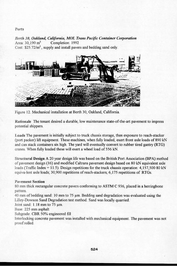
Berth 30, Oakland, California, MOL Trans Pacific Container Corporation Area 30, 190 m2 Completion: 1992 Cost: $25. 721m2
, supply and install pavers and bedding sand only.
Figure 12. Mechanical installation at Berth 30, Oakland, California.
Rationale The tenant desired a durable, low maintenance state-of-the-art pavement to impress potential shippers.
Loads The pavement is initially subject to truck chassis storage, then exposure to reach-stacker (port packer) lift equipment. These machines, when fully loaded, exert front axle loads of 890 kN and can stack containers six high . The yard will eventually convert to rubber tired gantry (RTG) cranes. When fully loaded these will exert a wheel load of 556 kN.
Structural Design A 20 year design life was based on the British Port Association (BPA) method of pavement design (16) and modified Cal trans pavement design based on 80 kN equivalent axle loads (Traffic Index = 11.5). Design repetitions for the truck chassis operation: 4,157,50080 kN equiva-lent axle loads; 30,900 repetitions of reach-stackers; 6,175 repetitions of RTGs.
Pavement Section 80 mm thick rectangular concrete pavers conforming to ASTM C 936, placed in a herringbone pattern. 40 mm of bedding sand: 10 mm to 75 flm. Bedding sand degradation was evaluated using the Lilley-Dowson Sand Degradation test method. Sand was locally quarried. Joint sand : 1. 18 mm to 75 flm Base 225 mm asphalt Subgrade: CBR 50% engineered fill Interlocking concrete pavement was installed with mechanical equipment. The pavement was not proof rolled.
524
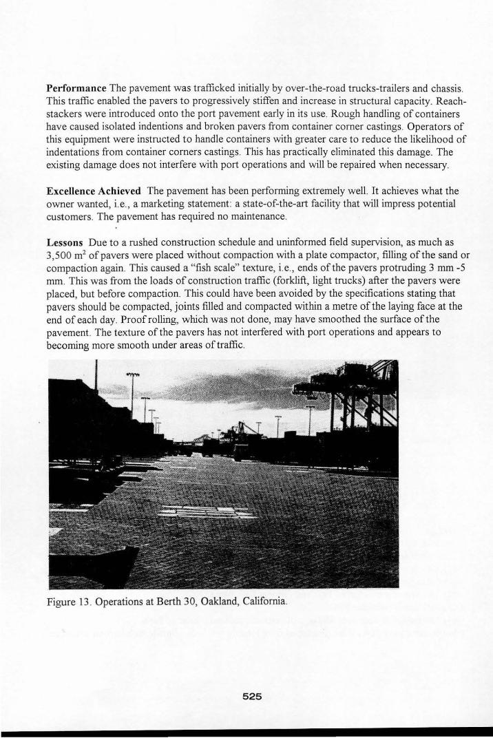
Performance The pavement was trafficked initially by over-the-road trucks-trailers and chassis. This traffic enabled the pavers to progressively stiffen and increase in structural capacity. Reachstackers were introduced onto the port pavement early in its use. Rough handling of containers have caused isolated indentions and broken pavers from container corner castings. Operators of this equipment were instructed to handle containers with greater care to reduce the likelihood of indentations from container corners castings. This has practically eliminated this damage. The existing damage does not interfere with port operations and will be repaired when necessary.
Excellence Achieved The pavement has been performing extremely well. It achieves what the owner wanted, i.e., a marketing statement: a state-of-the-art facility that will impress potential customers. The pavement has required no maintenance.
Lessons Due to a rushed construction schedule and uninformed field supervision, as much as 3,500 m2 of pavers were placed without compaction with a plate compactor, filling of the sand or compaction again. This caused a "fish scale" texture, i.e., ends of the pavers protruding 3 mm-5 mm. This was from the loads of construction traffic (forklift, light trucks) after the pavers were placed, but before compaction. This could have been avoided by the specifications stating that pavers should be compacted, joints filled and compacted within a metre of the laying face at the end of each day. Proof rolling, which was not done, may have smoothed the surface of the pavement. The texture of the pavers has not interfered with port operations and appears to becoming more smooth under areas of traffic.
Figure 13 . Operations at Berth 30, Oakland, California.
525
Port of New Orleans, Louisiana Area: 101,1 80 m2 total Nashville Avenue Marsahling Yard A: 44,520 m2
; Yard B: 32,380 m2; Yard C: 12,140 m2;
Louisiana Avenue Terminal: 12,140 m2
Completion: Yard A: 1995; Yard B: 1991; Yard C; 1992; Louisiana Avenue Terminal: mid-1 996. Cost $/m2
; Yard A: $50.16; Yard B:$38II ; Yard C; $4370; Louisiana Avenue Terminal: $51. 78. Costs include concrete pavers, bedding sand and base.
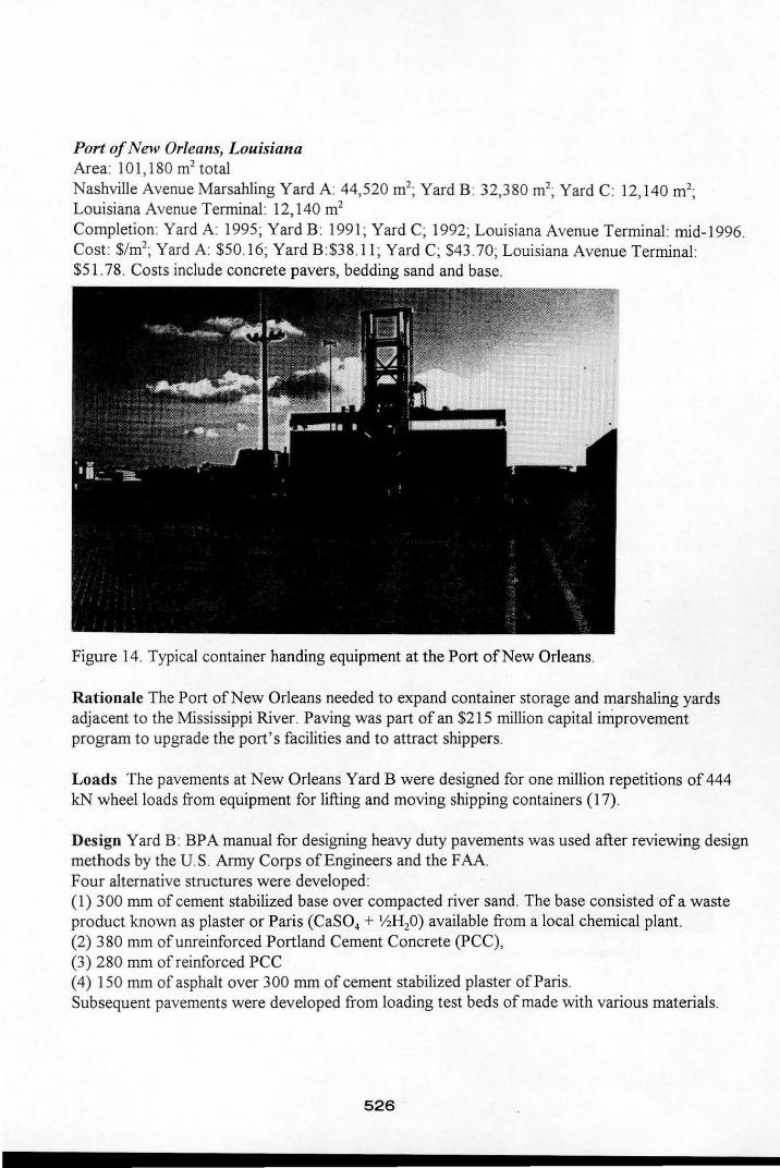
Figure 14. Typical container handing equipment at the Port of New Orleans.
Rationale The Port of New Orleans needed to expand container storage and marshaling yards adjacent to the Mississippi River. Paving was part of an $215 million capital improvement program to upgrade the port's facilities and to attract shippers .
Loads The pavements at New Orleans Yard B were designed for one million repetitions of 444 leN wheel loads from equipment for lifting and moving shipping containers (17).
Design Yard B: BP A manual for designing heavy duty pavements was used after reviewing design methods by the U.S . Army Corps of Engineers and the FAA. Four alternative structures were developed : (1) 300 mm of cement stabilized base over compacted river sand. The base consisted of a waste product known as plaster or Paris (CaSO, + YzH20) available from a local chemical plant. (2) 380 mm of unreinforced Portland Cement Concrete (PCC), (3) 280 mm of reinforced PCC (4) 150 mm of asphalt over 300 mm of cement stabilized plaster of Paris. Subsequent pavements were developed from loading test beds of made with various materials.
526
Pavement Section Nashville Avenue Yards: 80 mm thick rectangular concrete pavers conforming to ASTM C 936, placed in herringbone pattern. Louisiana Avenue Terminal: 80 mm thick, dentated, L-shaped pavers conforming to ASTM C 936, placed in an interlocking pattern. 25 mm of bedding sand: 10 mm to 75 11m. Joint sand: 1.18 mm to 75 11m. Base: CTB with plaster of Paris. Later construction used CTB only. Subgrade: River sand fill 15% CBR. Interlocking concrete pavement was installed with mechanical equipment. The pavements were not proof rolled.
Life-cycle Costs The Port of New Orleans staff conducted a life cycle cost study of the four pavement alternatives (18). They projected that concrete pavers would have the lowest maintenance over 40 years. Various price and discount rate scenarios were conducted, demonstrating that the pavers would have a lower life-cycle cost than PCC pavements, and break even at 15-20 years with asphalt. In light of the results oftheir analysis, concrete pavers on cement treated base were selected.
Performance The performance of the concrete pavers has been excellent. In one of the yards the wind blew an empty container off a four high stack of containers. The container comer gouged the pavers where it landed. The dozen or so units that were damaged were easily replaced. In one yard, there were isolated areas of heaving due to excess cement in the CTB. Some of these areas have been repaired. All yards have had no rutting, depressions or cracking from container comers.
Lessons learned Drain (weep) holes should be cast or drilled through the sides of curbs and drains. This will allow faster drainage of water from the site during construction after rainstorms.
Berth 208, Port of Tampa, Florida Area: Phase 1: 46,080 m2 Completion: 1995 Cost: $50.59/m2
; pavers, sand, base/subbase
Rationale In planning a new terminal, wharf and upland service area for Berth 208, the Port of Tampa required approximately 100,000 m2 of paving. Berth 208 was to be built over dredged marine deposits, miscellaneous soils and debris. While some settlement occurred during fill operations, more settlement was expected during the life of the pavement. This situation is typical to many port facilities (20).
The Port of Tampa typically constructs pavements with 150 mm of asphalt over 460 mm of compacted FDOT limerock base, a soft limestone material unique to Florida. Asphalt was never completely satisfactory in performance, so other systems were considered. These included unreinforced concrete over base, reinforced concrete and subbase, and concrete pavers over base. Interlocking concrete pavements were selected because subgrade and base settlement could be easily repaired by removing the paving units, adjusting the base, and reinstating them.
527
Loads The pavement cross section was developed to support 943 kN front axle load exerted by the container handlers over a 25 year period.
Structural Design Two design methods were used develop alternative cross sections. One was the BP A design method by 1. Knapton as written in the ICPI manual, "Port and Industrial Pavement Design with Concrete Pavers (20)." The other was a computer program called "Lockpave" developed by Brian Shackel, Ph.D. of Australia (21). Both rely on layered elastic design theory, i.e., limiting strains in the subgrade and base as a design criteria. The solution for aggregate base from the Lockpave program was selected. The Knapton manual develops thickness design for stabilized bases only. This is because unstabilized bases often will rut early in their life due to excess strains.
Limerock base was considered as a base but rejected due to its lack of strength. 405 mm of 12 MPa lean concrete was considered but also rejected. It was unable to settle with the subgrade without cracking, and it had a high cost. A high strength, hard limestone aggregate from Mexico was identified as unstabilized base material of choice. It offered high particle soundness, ability to drain, ease of construction and low cost. Plate bearing tests were conducted on the surface of the compacted, unstabilized aggregate base material. The tests confirmed that it could withstand the expected wheel loads and strains at the bottom and under the bedding sand/paver layer (21).
Pavement cross section 80 mm thick, dentated, L-shaped pavers, conforming to ASTM C 936, placed in an interlocking pattern. 25-40 mm of bedding sand: 10 mm to 75 /.lm. Joint sand: 1.18 mm to 75 /.lm. Base: 460 mm of un stabilized hard limestone. A geogrid was placed at 230 mm from the bottom of the base. Subgrade: Sand fill compacted to 300 mm depth to 15% CBR. Native soil: dredged fill. Interlocking concrete pavement was installed with mechanical equipment. The pavement was not proof rolled.
Life-cycle costs A life-cycle study projected costs over 40 years and demonstrated that interlocking concrete pavements would be less expensive than the alternatives. The concrete pavers were estimated to have lower maintenance costs than asphalt after the sixth year of service.
Performauce This project was completed late in 1995 so an assessment of performance is premature. The use of an unstabilized material for the base is not typical to heavy duty port (or airport) pavement design in North America. Its use represents higher risk of elastic deformation and eventual rutting from loads. However, the risk may be a satisfactory trade-off in view of the lower initial cost and low cost of repairs from subgrade settlement.
The remaining 46,500 m2 of paving to be done is waiting for a tenant to justify the additional investment. The promise of concrete pavers and their low maintenance can be a major selling feature by the Port of Tampa to prospective tenants.
528
Figure 15 . Finished pavement at Berth 208 prior to traffic.
Lessons The following were learned at Tampa and several of the other projects involving mechanical installation: The base construction requires continual monitoring for compliance to specified surface tolerances. Monitoring will reduce the likelihood of an excessive thickness of bedding sand (over 40 mm) being used to compensate for unevenness.
Concrete pavers should be manufactured well within their specified dimensional tolerances, especially when intended for mechanical installation. Out-of-tolerance units/layers can make them difficult or impossible to fit with layers in place on the bedding sand. Marking loads of pavers for their date/sequence of production can help the contractor determine where to fit layers.
Conclusions
Interlocking concrete pavement is new to ports and airports' in the U.S.A. and Canada. Because it is new, interlocking concrete pavement is often subject to greater skepticism, scrutiny, and criticism from engineers than conventional pavements. This reaction can be a veiled rejection based on costs, fear of the unknown, lack of technical experience and confidence in the pavement system. Therefore, confidence building through the technical experience of others is essential to demonstrating the benefits of interlocking concrete pavement to North American design professionals.
The persons who designed and own these projects understood that pavement--whether asphalt, PCC, or interlocking concrete--must be carefully engineered for each situation. The degree of technical success of each of these projects was dependent on the degree of excellence applied to structural analysis, detailing and construction. Continual, systematic documentation of successful port and airport projects in North America can increase the body of knowledge, experience, and achieve excellent projects. The projects documented here are intended to provide that opportunity.
529
References
I. King P.M., and Smith D.R., "Interlocking Concrete Airfield Pavements", Concrete International magazine, Volume 13, Number 12, December 1991, pages 24-27.
2. Lary J., Petit R., and Smallridge M., "Concrete Block Pavement Taxiway Construction," in Proceedings, AircraftlPavement Interaction-An Integrated System, September 4-6, 1991, Kansas City, Missouri, American Society of Civil Engineers, New York, New York, 1991, pages 244-257.
3. Lary J., Petit R. and Smallridge M., "DFW Concrete Block Pavement Taxiway Construction," in Volume 2 of Proceedings, Fourth International Conference on Concrete Block Paving, Pave New Zealand '92, Porirua, New Zealand, 1992, pages 199-208.
4. Personal correspondence dated November 27, 1990 with Victor Nartz, Air Transport Association, Fort Worth, Texas.
5. Advisory Circular 150/5320-6C "Airport Pavement Design and Evaluation," U.S. Federal Aviation Administration, Washington, D.C., 1978.
6. Smallridge M., Bodie R., " A Review of Specification Requirements with Respect to time on the Concrete Blocks Used for DallasIFort Worth International Airport," in Volume I of Proceedings, Fourth International Conference on Concrete Block Paving, Pave New Zealand '92, Porirua, New Zealand, 1992, pages 133-142.
7. Canadian Standards Association, Precast Concrete Pavers CSA A231.2-M85, Rexdale, Ontario, Canada, 1985.
8. Lilley AA and Dowson AJ., "Laying Course Sands for Concrete Block Pavil).g," in Proceedings, Third International Conference on Concrete Block Paving, Rome, Italy, May 17-19, 1988, Pavitalia, Rome, pages 457-462.
9. Scherling D.J., "Interlocking Concrete Pavers for Aircraft Parking Aprons, FDOT Aviation Office 1992 Demonstration Project, St. Augustine, Florida,." presentation and paper submitted to the Florida Meeting of the American Society of Civil Engineers, September 25, 1992,5 pages.
10. Reynolds, Smith and Hill, Inc. Consulting Engineers, St. Augustine Airport, Project 592 0900 007, Jacksonville, Florida, 1992.
II. ASTl\.1 C 936, "Standard Specification for Solid Concrete Interlocking Paving Units," Annual Book of Standards, Volume 4.05, American Society of Testing and Materials, Philadelphia, Pennsylvania, 1995.
530
12. Patroni 1.F., Concrete Block Pavers- Pavement Performance Evaluation, Dallas/For Worth International Airport, Texas, Harding Lawson Associates, Reno, Nevada, June 6, 1995.
13. McQueen RD., Knapton 1., Emery J. and Smith D.R., Airfield Pavement Design with Concrete Pavers, Interlocking Concrete Pavement Institute, Second Edition, TR-4, Sterling, Virginia, 1995.
14. McQueen RD., Knapton 1., Emery 1., and Smith D.R., "Airfield Pavement Design with Concrete Pavers," in Proceedings, Second International Workshop on Concrete Block Paving, Oslo, Norway, June 17-18,1994, Norwegian Concrete Association, Oslo, Norway, pages 372-389.
15. Murray B., "Construction of Concrete Block Pavers at L.I. McArthur Airport," in Proceedings of the Eighteenth Annual Airport Conference, Hershey, Pennsylvania, March 7-9, 1995, Federal Aviation Administration Eastern Region and Pennsylvania State University, 1995, 5 pages.
16. Knapton 1., The Structural Design of Heavy Duty Pavements for Ports and Other Industries, British Ports Federation (now the British Ports Association), London, England, 1988.
17. Sanders H.C., "Concrete Pavers at the Port of New Orleans," unpublished report, Port of New Orleans, Louisiana, 1991, 10 pages.
18. Keller D., "A Comparative Economic Analysis of Pavement for Nashville Marshaling Yards," unpublished report, Port of New Orleans, February 1991, 25 pages.
19. McGillivray RI. and Fielland C.E., "Selection of a Pavement System for Heavily Loaded Marine Terminal," in Proceedings, Ports 95 Conference, March 13-15,1995, Tampa, Florida, American Society of Civil Engineers, New York, New York, pages 1057-1067.
20. Knapton 1. and Smith D.R (editor), Port and Industrial Pavement Design with Concrete Pavers, Interlocking Concrete Pavement Institute, TR-2, Sterling, Virginia, 1994.
2l. Shackel B., LOCKP AVE software computer program, F. von Langsdorfi' Licensing Ltd, Mississauga, Ontario, Canada, 1995.
22. McGillivray R.I., "Tampa Port Authority Berth 208 Site Development in Situ Pavement Base Material Tests," unpublished report, ARMAC Engineers, Inc., Tampa, Florida, March 1995.
531