Embed Size (px)
Citation preview

Schlu
mberg
er
Confidential
2011 Middle East and North Africa Perforating
Symposium - MENAPS
Acid Diversion Technique and Perforation Job Design
Improves Injection Profile in Carbonate Reservoir
Jamal M.A Al-Gub, Tsuneo Horikoshi, and Kazutoshi Ichikawa, Bunduq Co., Ltd., Alan
Salsman SPE, Fardin Ali Neyaei SPE, and Fidias Vasquez SPE, Schlumberger.
Presenter: Fardin M. Ali Neyaei

2
Carbonate Reservoir
• Continuous reservoir
• Four layers
• Limestone – Dolomite mix
• Significant permeability
variations
Perf
Interval
Top Bottom Length
(ft)
Perm
(md)
1 x776 x798 22 9.5
2 x798 x828 30 44.7
3 x828 x882 54 16
4 x892 x912 20 3.6
Volumes10
PU/division
3
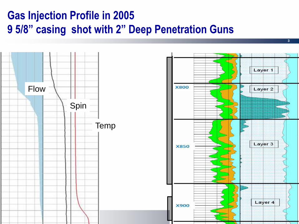
Gas Injection Profile in 2005
9 5/8” casing shot with 2” Deep Penetration Guns
Flow
Spin
Temp

4
2009 Workover
• Convert dual water string water injector into single string
gas injector
• Cement 7” liner inside existing 9 5/8” casing
• Remove completion and squeeze perfs
• Re-perforate same intervals and stimulate
• Effort made to improve injection profile

5
Perforation Design
New 7” Casing Completion inside 9 5/8”
Perforating System #1, 7.3 g
60º Phasing, 6.00 spf
Pore Pressure: 4200 psi
Vertical Stress: 8284 psi
Rock UCS: 8000 psi
Rock Type: Limestone
Formation
MR Scanner Measure Depth
Cement
Cement
Brine
0 deg
0
0
5
5
10
10
15
15
20
20
Angle Clearance Total Pen Form Pen Form Dia Csg EH Dia(deg) (in) (in) (in) (in) (in)
0 4.28 6.93 3.94 0.15 0.10/0.07
60 2.60 8.20 5.21 0.21 0.13/0.10
120 0.46 11.72 8.73 0.32 0.21/0.16
180 0.00 11.70 8.71 0.34 0.22/0.17
240 0.46 11.72 8.73 0.32 0.21/0.16
300 2.60 8.20 5.21 0.21 0.13/0.10
Average 1.74 9.74 6.76 0.28 0.17/0.13
AOF (in²/ft) 0.08 at 6.00 spf
API: Pen 21.80 in, EH Dia 0.22 in, 19B 1st Ed.
Company: Bunduq Well: EB-48
Results are based on API and other test data of Schlumberger perforating systems as well as computermodeling of perforated completions. Results are provided in good faith without warranty
File: C:\Program Files\Schlu...nduq EB 48 paper Arab D2.SP8SPAN Version 8.0l© Copyright 2009 Schlumberger
Perforating System #2, 38.8 g
72º Phasing, 5.00 spf
Pore Pressure: 4200 psi
Vertical Stress: 8284 psi
Rock UCS: 8000 psi
Rock Type: Limestone
Formation
MR Scanner Measure Depth
Cement
Cement
Brine
0 deg
0
0
5
5
10
10
15
15
20
20
Angle Clearance Total Pen Form Pen Form Dia Csg EH Dia(deg) (in) (in) (in) (in) (in)
0 1.78 22.55 19.56 0.67 0.37/0.33
72 1.05 24.47 21.49 0.80 0.44/0.40
144 0.13 24.93 21.95 0.74 0.41/0.37
216 0.13 24.93 21.95 0.74 0.41/0.37
288 1.05 24.47 21.49 0.80 0.44/0.40
Average 0.82 24.27 21.29 0.75 0.42/0.37
AOF (in²/ft) 0.55 at 5.00 spf
API: Pen 59.20 in, EH Dia 0.43 in, 19B 1st Ed.
Company: Bunduq Well: EB-48
Results are based on API and other test data of Schlumberger perforating systems as well as computermodeling of perforated completions. Results are provided in good faith without warranty
File: C:\Program Files\Schlu...nduq EB 48 paper Arab D2.SP8SPAN Version 8.0l© Copyright 2009 Schlumberger
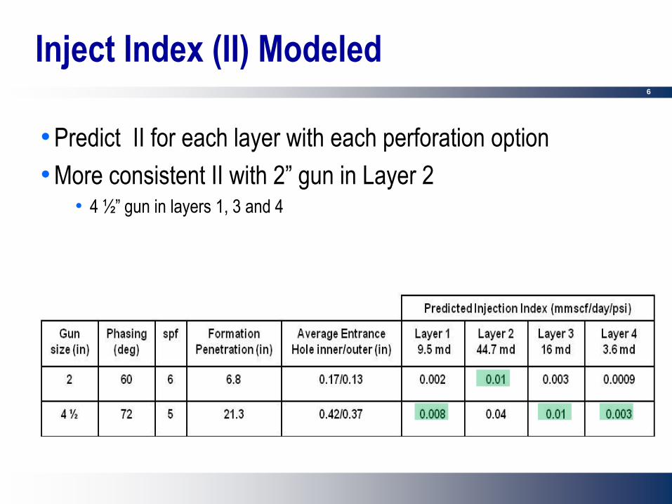
2” gun, 6 spf
Pen – 6.8”, avg EH – 0.17/0.13 4.5” gun, 5 spf
Pen – 21.3”, avg EH – 0.42/0.37
6
Inject Index (II) Modeled
• Predict II for each layer with each perforation option
• More consistent II with 2” gun in Layer 2 • 4 ½” gun in layers 1, 3 and 4

7
Matrix Acidizing Design
• Considered 3 different acid scenarios • 15% HCl
• 15% HCl + 5% Self Diverting Acid
• 28% Emulsified Acid + 5% Self Diverting Acid
•+15% HCl post flush
• 15% HCl typical in this area
• Modeled using proprietary PC based modeling software
• Acid and diverter placed with coiled tubing • Assists with diversion requirement

8
Radial Penetration Prediction
0 2 4 6 8
Radial Penetration (ft)
8700
8750
8800
8850
8900
8950
Zon
e M
D (ft)
HCl 15%
StimCADE*
*Mark of Schlumberger
Radial Penetration Plot
1-2 HCL ONLY02-16-2009
• 15% HCl
9.5 md
44.7 md
3.6 md
16 md

9
Radial Penetration Prediction
• 15% HCl + 5% self diverting acid
0 2 4 6
Radial Penetration (ft)
8700
8750
8800
8850
8900
8950
Zone
MD
(ft)
HCl 15%
Self Diverting Acid 5%
StimCADE*
*Mark of Schlumberger
Radial Penetration Plot
1-2-hcl-sda02-16-2009

10
Radial Penetration Prediction
• 28% Emulsified Acid + 5% Self Diverting Acid +15% HCl
0 1 2 3 4 5
Radial Penetration (ft)
8700
8750
8800
8850
8900
8950
Zone
MD
(ft)
Emuslified Acid 28%
Sef Diverting Acid 5%
HCl 15%
StimCADE*
*Mark of Schlumberger
Radial Penetration Plot
1-2 sda5% with 15%HCL post flush02-16-2009

11
Wormhole Length Prediction
• 15% HCl
0 50 100 150 200 250 300
Volume (bbl)
0
0.5
1.0
1.5
2.0
2.5
3.0
Wor
mho
le L
engt
h (ft)
Zone 1
Zone 2
Zone 3
Zone 4
1
--- Treatment Fluids --- 1 - HCl 15%
StimCADE*
*Mark of Schlumberger
Acid Placement: Wormhole length vs. Volume by Zone
1-2 HCL ONLY02-16-2009

12
0 50 100 150 200 250 300
Volume (bbl)
0
0.5
1.0
1.5
2.0
2.5
3.0
Wor
mho
le L
engt
h (ft)
Zone 1
Zone 2
Zone 3
Zone 4
1 2 1 2 1 2 1 2 1
--- Treatment Fluids --- 1 - HCl 15% 2 - 5% Self Diverting Acid
StimCADE*
*Mark of Schlumberger
Acid Placement: Wormhole length vs. Volume by Zone
1-2-hcl-sda02-16-2009
Wormhole Length Prediction
• 15% HCl, 5% Self Diverting Acid

13
Wormhole Length Prediction
• 28% emulsified acid, 15% HCl, 5% self diverting acid
0 50 100 150 200 250 300
Volume (bbl)
0
0.5
1.0
1.5
2.0
2.5
3.0
Wor
mho
le L
engt
h (ft)
Zone 1
Zone 2
Zone 3
Zone 4
1 2 1 2 1 2 1 2 1 3
--- Treatment Fluids --- 1 - 28% Emuslion Acid 2 - 5% Self Diverting Acid 3 - HCl 15%
StimCADE*
*Mark of Schlumberger
Acid Placement: Wormhole length vs. Volume by Zone
1-2 sda5% with 15%HCL post flush02-16-2009

14
Final Stimulation Design
28% emulsified acid, 5% self diverting acid, 15% HCl
•What happens in each stage?

15
Execution- Pumping Record
02:15:16 03:21:56 04:28:36 05:35:16 06:41:56
Time - hh:mm:ss
0
125
250
375
500
625
750
875
1000
Pre
ssu
res -
ps
i
0
0.5
1.0
1.5
2.0
2.5
3.0
3.5
4.0
To
tal P
um
p R
ate
- bb
l/min
8750
8775
8800
8825
8850
8875
8900
8925
8950
CT
Dep
th -
ft
WH Press.
Total Pump Rate
CT Depth
Diversion deltaP
CCAT*
© Schlumberger 1994-2006
Pressure and Rate
BUNDUQEB4809-April-2009
Figure-13: Execution chart; pumping rate, CT depth and wellhead pressure versus operational time
x950
x925
x900
x875
x850
x825
x800
x775
x750
Diversion Delta P

16
Immediate Results: Injectivity test
0
350
700
1050
1400
1750
2100
0 200 400 600 800 1000 1200 1400 1600 1800
Time
Well
Head
Pre
ssu
re (
Psi)
0.00
1.00
2.00
3.00
4.00
5.00
6.00
Rate
(b
pm
)
WHP-1 WHP-2 RATE-1 RATE-2
Injectivity test before and after the job, 1 being before and 2 being after the job

17
RESULTS
PRODUCTION RUN LOGS RUN IN 2005
AND 2009 DURING WATER PUMP-IN TEST
PLT - 2009 PLT - 2005

18
Well Injection Results
• Injection profile improved
• Injection rate maintained
• Injection effect seen in nearby well
• Initial increase in oil production

19
Conclusions
• Unique situation where 2 completion strategies could be
evaluated on the same interval
• Combination of the tailored perforating program + the acid
matrix stimulation improved the injection profile
• Improve bottom zone with additional perforating or Dynamic
Underbalance clean-up
• Good set of well data + a team approach to planning and
execution = successful job

20
Questions?