Embed Size (px)
Citation preview
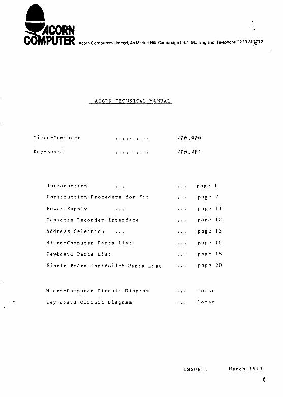
WORNl U T fcKAcorn Computers Limited, 4a Market Hill. Cambridge CB2 3NJ, England. Telephone 0223 31.^72
ACORN TECHNICAL MANUAL
Micro-Computer
Key-Board
200,000
200,00 I
Introduction ..,
Corstruction Procedure for Kit
Power Supply ...
Cassette Recorder Interface
Address Selection ...
Micro-Computer Parts List
Key-Board Parts List
Single Board Controller Parts List
page 1
page 2
page 11
page 12
page 13
page 1 6
page 18
page 2 0
Micro-Computer Circuit Diagram
Key-Board Circuit Diagram
loose
loose
ISSUE 1 March 1979
INTRODUCTION
The Acorn Micro-Computer employing tfte 6502 Micro Processor isa versatile circuit board which may Be used in at least threeways:-
1. As a Single Board Controller with a program in the pair of74S571 PROM's or in the EPROM socket which may be 4, 8 or16 K with single or multiple power supplies. Two RAM/10ICfs may be fitted giving 32 individually programmable 10lines and 256 bytes of RAM. IK of further RAM may be fittedif requir ed.
2. As a machine code computer with an 8 digit x 7 segment HEXdisplay, HEX keyboard and a cassette interface all on asecond board, which is accessed by one of the RAM/10 I.C.'s.Programs are entered and stored in the IK of user RAM space.
3. As the Central Processing Unit for a complete computingsystem. All the 6502 data, address and control lines leavethe board via a 32 way D.I.N. connector, which will then haveaccess via a parallel back plane to extension memory, aVisual Display Unit, floppy disc drive, etc.. The Key-Boardmay be retained for its cassette interface and an ASCIIKey-Board will also connect on to the HEX keyboard 10 gort.Systems such as this are capable of supporting high levellanguages, e.g. BASIC or PASCAL and may be used at home, inbusiness or in the laboratory. Powerful peripherals suchas high speed printers may be interfaced and direct controlof external apparatus is possible.
Included in this manual are the construction details necessaryto assemble the Micro-Computer and Key-Board Kit. Also detailson power supplies, cassette interfaces and address configurationswhich will be required however the Acorn is used.
CONSTRUCTION PROCEDURE
Before you start
Before attempting to assemble the Acorn kit check that allthe component parts are present and that none have beendamaged. It is worthwhile taking a few minutes to makesure that you can identify all the components. Sometimescomponents will be substituted in case of supply difficulties.For instance, ten off 0.047 uF capacitors may replace theten 0.1 uF capacitors shown on the parts list. The componentssubstituted will in no way be detrimental to the Acorn's operationAlso some manufacturers have similar but different type numberse.g. for the CMOS a CD4011 from R.C.A. may be replaced by an"MM5611 from National Semiconductor.
For capacitors note that the value may be expressed in one oftwo vayss-
100 nF =
10 nF =
1 nF =
0. 1 nF =
0. 1 uF
0.01 uF
1000 pF
100 pF
If in doubt about the capacitor values, count the number ofeach of type supplied in the kit and then identify them usingthe parts list quantities.
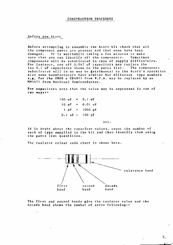
The resistor colour code chart is shown here.
tolerance band
The first and second bands give the resistor value and thedecade band shovs the number of zeros following:-
0123456789
BlackBrownRedOrangeYellowGreenBlueVioletGreyWhite
e.g. Yellow, Violet, Orangeis Yellow, Violet = 4,7and Orange = 3 zeros i.e. 000.So the value is 47000 ohms,i.e. 47 kilo-ohms or 47K.
The tolerance band is red for j+ 2%, gold for +_ 5% or silverfor + 10%, any of these are suitable for the ACorn kit.
Ensure that no components are concealed in the packing materialand retain the packing material in case you have cause to returnthe kit.
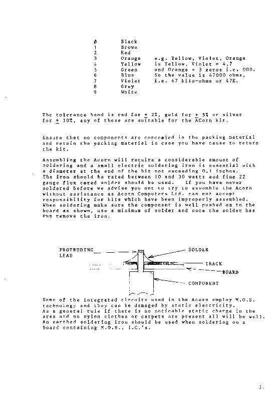
Assembling the Acornsoldering and a smalla diameter at the endThe iron should be ragauge flux cored soldsoldered before we adwithout assistance asresponsibility for kiWhen soldering make sboard as shown, userun remove the iron.
will require a considerable amount ofelectric soldering iron is essential withof the bit not exceeding 0. 1 inches,
ted between 10 and 30 watts and fine 22er should be used. If you have nevervise you not to try to assemble the AcornAcorn Computers Ltd. can not acceptts which have been improperly assembled.ure the component is well pushed on to theminimum of solder and once the solder has
PROTRUDINGLEAD
OARD
—-• COMPONENT
Some of the integrated circuits used in the Acorn employ M.O.S.technology and they can be damaged by static electricity.As a general rule if there is no noticable static charge in thearea and no nylon clothes or carpets are present all will be well.An earthed soldering iron should be used when soldering on aboard containing M.O.S., I.C.'s.

T h e A c o r n P r i n t e d C i r c u i t B o a r d s a r e d o u b l e s i d e d , t h r o u g hh o l e p l a t e d g l a s s f i b r e a n d a r e m a n u f a c t u r e d to t h e h i g h e s ts t a n d a r d s . A l a y e r o f g r e e n s o l d e r r e s i s t e n s u r e s t h a ta c c i d e n t a l s o l d e r s p l a s h e s d o n o t s t i c k to t h e t r a c k s a n d ac l e a r l y m a r k e d w h i t e s i l k s c r e e n i n d i c a t e s c o m p o n e n tp o s i t i o n s . E x a m i n e t h e t w o b o a r d s f o r f a u l t s o r d a m a g eb e f o r e p r o c e e d i n g . It is n o t n e c e s s a r y to s o l d e r t h r o u g hh o l e s w h i c h c o n n e c t o n e s i d e of a b o a r d to t h e o t h e r a n d don o t h a v e a c o m p o n e n t l e a d in t h e m . I n d e e d a t t e m p t i n g to d oso c a n b r e a k t h e t h r o u g h h o l e p l a t i n g a n d t h u s t h e c o n n e c t i o n .
A s s e m b l i n g t h e A c o r n w i l l t a k e a n h o u r o r t w o , so c l e a r as p a c e a n d c o n t i n u e a s f o l l o w s .
I n t e g r a t ed C i r c u i t S o c k e t s
T h e A c o r n is s u p p l i e d w i t h a f u l l s e t o f i n t e g r a t e d c i r c u i cs o c k e t s a n d t h e s e s h o u l d b e f i t t e d to t h e t w o c i r c u i t b o a r d s .T h e s o c k e t s m u s t b e f i t t e d t h e r i g h t w a y r o u n d , o n t h e c i r c u ib o a r d v i e w i n g it f r o m t h e t o p p i n 1 of a n I . C . is i d e n t i f i e da s s h o w n -
T O P V I E W
Pin 1
T h e s o c k e t s w i l l h a v e e i t h e r a 4 5 c h a m f e r f o r p i n 1 or as e m i c i r c u l a r c u t o u t a s s h o w n -
f IN
Note that on the Microcomputer board IC1 is the opposite wayround to the other sockets nearby. Fit the sockets one ata time and ensure that they are pressed fully down with noleads bent under the socket before first soldering two diag-onally opposite pins at the corners. Check that the socketis the right way round and successfully fitted before solderingthe rest of the pins.
A socket is also supplied for the Address link selection onthe Micro Computer board.
There is no need to snip off the excess of the socket pins.
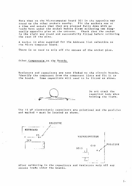
Other Components on the Boards
Resistors and capacitors are next fitted to the circuit boards.Identify the component from the component lists and fit it tothe board. Some capacitors will need to be fitted as shown.
Do no t crack thecapacitor body whenbending the leads.
The 15 uF electrolytic capacitors are polarised and the positiveend marked + must be located as shown.
POSITIVE
KEYBOARD /
* - 4 - * ^ MICROCOMPUTER
IC3
CIO POSITIVE
IC 1 3 |
-I_L
After soldering in the capacitors and resistors snip off anyexcess leads under the boards.
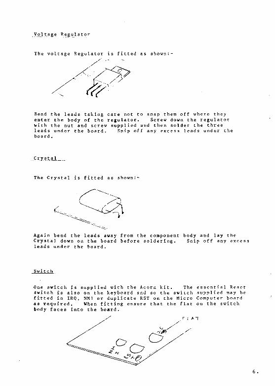
Vj?J tag e Regulator
The voltage Regulator is fitted as shown
Bend the leads taking care not to snap them off where theyenter the body of the regulator. Screw down the regulatorwith the nut and screw supplied and then solder the threeleads under the board. Snip off any excess leads under theboard .
-_Cr_y_st.al_
The Crystal is fitted as shown:-
Again bend the leads away from the component body and lay theCrystal down on the board before soldering. Snip off any excessleads under the board.
Switch
One switch is supplied with the Acorn kit. The essential Resetswitch, is also on the keyboard and so the switch supplied may befitted in IRQ, NM1 or duplicate RST on the Micro Computer boardas required. When fitting ensure that the flat on the switchbody faces into the board.
There is no need to fit the switch now if you do not knowwhere you will require it.
Keyboard
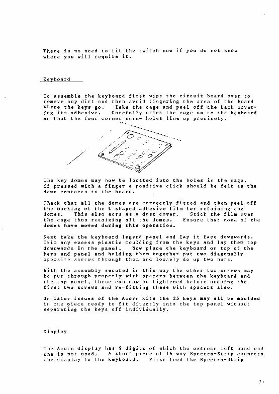
To assemble the keyboard first wipe the circuit board over toremove any dirt and then avoid fingering the area of the boardwhere the keys go. Take the cage and peel off the back cover-ing its adhesive. Carefully stick the cage on to the keyboardso that the four corner screw holes line up precisely.
The key domes may now be located into the holes in the cage,if pressed with a finger a positive click should be felt as thedome contacts to the board.
Check that all the domes are correctly fitted and then peel offthe backing of the L shaped adhesive film for retaining thedomes. This also acts as a dust cover. Stick the film overthe cage thus retaining all the domes. Ensure that none of thedomes have moved during this operation.
Next take the keyboard legend panel and lay it face downwards.Trim any excess plastic moulding from the keys and lay them topdownwards in the panel. Now place the keyboard on top of thekeys and panel and holding them together put two diagonallyopposite screws through them and loosely do up two nuts.
With the assembly secured in this way the other two screws maybe put through properly with spacers between the keyboard andthe top panel, these can now be tightened before undoing thefirst two screws and re-fitting these with spacers also.
On later issues of the Acorn kits the 25 keys may all be mouldedin one piece ready to fit directly into the top panel withoutseparating the keys off individually.
D i splay
The Acorn display has 9 digits of which the extreme left hand endone is not used. A short piece of J6 way Spectra-Strip connectsthe display to the keyboard. First feed the Spectra-Strip

through the slot in the keyboard into the printed circuitboard. Solder leads 1 and 16 first and then, if all is well,solder the rest of the leads.
TWO UNUSEDHOLES AT L.H.S.
Lay the display face upwards on the Spectra-Strip and solderthe strip into the display. Note that the two left hand endconnections on the display are not used.
The display may be pushed down on to the beyboard taking carenot to over-stress the solder joints on the Spectra-Strip.
Connect in_g__ t_h e two bo ards
Connection between the Micro Computer and keyboard is achievedusing a piece of 20 way 'Spectra-Strip' approximately 6 incheslong. In order that the keyboard can be mounted above theMicro Computer the 'Spectra-Strip' must enter the keyboard fromthe bottom and the Micro Computer from the top as shown:-
KEYBOARD
2 0 WAY'SPECTRA-STRIP'
MICRO COMPUTER
Before insertion check that the ends of the Spectra-Strip areproperly stripped off and then with the strip pushed well home
solder the connections to pins 1 and 20 first.continue and solder the other 18 connections.other end.
If all is wellRepeat for the
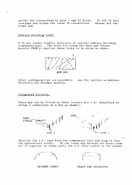
Address Decoding L ink s
A 16 pin socket enables selection of various Address Decodingconfigurations. The Acorn kit using the Blue and YellowMonitor PROM's requires these links to be wired as shown.
ADR SEL
Other configurations are possible;Selection for further details.
see the section on Address
Integrated Circuits
These may now be fitted in their sockets pin 1 is identified byeither a semicircle or a dot as shovn:-
SEMI
PIN 1
4 * !DOT
i
*• PIN 1
Identify the I.C. type from the components list and plug it intothe appropriate socket. If the leads are splayed out press themall in together as shown until the I.C. fits easily to the socket.
/ •
SPLAYED LEADS READY FOR INSERTION

Take care that no IC leads get hent under the IC when insertingand remember that IC ] on the Micro Computer board is theopposite way round to its neighbours.
Mounting the _B_o ards together
Four sets of screws, nuts and spacers are provided to mountthe keyboard on top of the Micro Computer board. This isadvisable as it stops the interconnecting 'Spectra-Strip' frombeing continually flexed and strained.
.-SwjLjLc h i n_g__ Chi
C h e c k that all c o m p o n e n t s are pr o p e r l y f i t t e d , that all IC's arein the right p o s i t i o n s and the right way ro u n d . C h e c k that thepower supply p o l a r i t y is c o r r e c t , as in the s e c t i o n on PowerS u p p l i e s f o l l o w i n g .
Switch on and press the Reset b u t t o n , the d i s p l a y should indicateeight d o t s . If all is well proceed to the p r o g r a m m i n g m a n u a l .
Should the kit not function switch off i m m e d i a t e l y and feel eachI.C. to see if it is hot. If any a r e , check that they arecor r e c t l y i n s e r t e d . Check the power c o n n e c t i o n s and check thatall the a s s e m b l y steps have been followed c o r r e c t l y . Do notattempt to u n s o l d e r any com p o n e n t s or sockets w i t h 4 leads ormore as the print e d circuit board may su f f e r . Instead cut outfaulty c o m p o n e n t s so that their leads may be remov e d one at a t i m e .
JO.
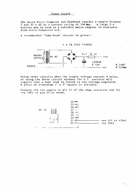
Power Supply
The Acorn Micro Computer and Keyboard require a supply between7 and 35 v DC at a current rating of 500 mA. A large 9.vbattery may be used or a suitable mains adaptor is availablefrom Acorn Computers Ltd.
A recommended 'home-brew' circuit is given:*-
4 x IN 4002 DIODES
EARTH8.5vDC@ 500nk
Using other circuits when the supply voltage exceeds 9 volts,or using the above circuit without the 4.7 resistor willrequire that a heat sink is fitted to the voltage regulator.A piece of aluminium 1" x 2" square is suitable.
Connect the +ve supply to pin 31 of the edge connector and the-ve (OV) to pin 32 as shown.
IC 13 ILL2 5 - j26 ~«-l2 7 -•-'
28 — i2 9 --30 -H3 1 -»"—3 2 ~ _
+ve (+7 to +35v)-ve (OV)
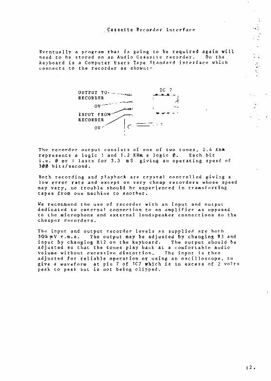
Cassette Recorder Interface
Eventually a program that is going to be required again willneed to be stored on an Audio Cassette recorder. On thekeyboard is a Computer Users Tape Standard interface whichconnects to the recorder as shown:-
OUTPUT TO—-RECORDER
INPUT FROM-'RECORDER
The recorder output consists of one of two tones, 2.4 KHxrepresents a logic 1 and 1.2 KHat a logic 0, Each biti.e. 0 pr 1 lasts for 3.3 mS giving an operating speed of300 bits/second.
Both recording and playback are crystal controlled giving alow error rate and except on very cheap recorders whose speedmay vary, no trouble should be experienced in transferringtapes from one machine to another.
We recommend the use of recorder with an input and outputdedicated to external connection to an amplifier as opposedto the microphone and external loudspeaker connections on thecheaper recorders.
The input and output recorder levels as supplied are both3QQ mV r.m.s. The output may be adjusted by changing R3 andinput by changing R12 on the keyboard. The output should beadjusted so that the tones play back at a comfortable audiovolume without excessive distortion. The input is thenadjusted for reliable operation or using an oscilloscope, togive a waveform at pin 7 of IC7 which is in excess of 2 voltspeak to peak but is not being clipped.
12,
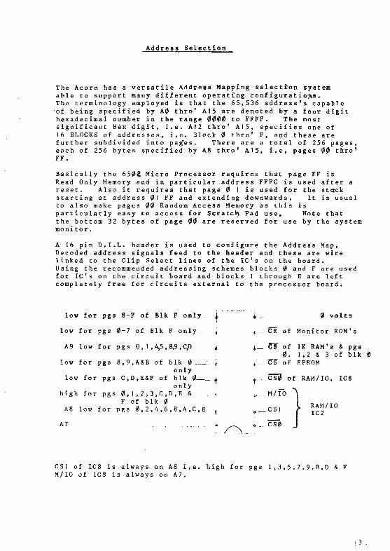
Address Selection
The Acorn has a versatile Address Mapping selection systeaiable to support many different operating configurations.The terminology employed is that the 65,536 address's capableof being specified by A0 thro' A15 are denoted by a four digithexadecimal number in the range 0000 to FFFF . The roostsignificant Hex digit, i.e. A12 thro' A15, specifies one of16 BLOCKS of addresses, i.e. Block 0 thro' F, and these arefurther subdivided into pag'es. There are a total of 256 pages,each of 256 bytes specified by A8 thro' A15, i.e. pages 00 thro1
FF.
Basically the 6502 Micro Processor requires that page FF isRead Only Memory and in particular address FFFC is used after areset. Also it requires that page 0 1 is used for the stackstarting at address 01 FF and extending downwards. It is usualto also make pages 00 Random Access Memory as this isparticularly easy to access for Scratch Pad use, Note thatthe bottom 32 bytes of page 00 are reserved for use by the systemmonitor.
A 16 pin D.I.L. header is used to configure the Address Map,Decoded address signals feed to the header and these are wirelinked to the Clip Select lines of the IC's on the board.Using the recommended addressing schemes blocks 0 and F are usedfor IC's on the circuit board and blocks 1 through E are leftcompletely free for circuits external to the processor board.
low for pgs 8-F of Blk F only_ j. i_ 0 volts
low for pgs 0-7 of Blk F only _ J * _ ITE of Monitor ROM's
A9 low for pgs 0,1 ,4,5,8*9,^ ^ ^_ CS* of IK RAM' s & pgs0. 1 ,2 & 3 of blk
low for pgs 8,9,A&B of blk 0- \ 6 ,. CS of EPROMonly
low for pgs C,D,E&F of blk 0 <only
high for pgs 0 , 1 , 2 , 3 , C , D , E & ._._ <F of blk 0 ,
A8 low for pgs 0,2,4,6,8,A,C,E 3 ^ _ C S 1 > IC2
A7 ._ t
*_ CS0 of RAM/10, IC8
CS1 of IC8 is always on A8 i,e. high for pgs 1 ,3 . 5 , 7 . 9 . B,D & FM/IO of IC8 is always on A7.
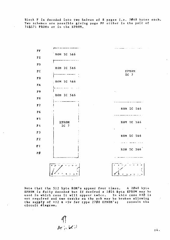
Block F is decoded into two halves of 8 pages i.e. 2048 bytes each.Two schemes are possible giving page FF either in the pair of74S571 PROMs or in the EPROM.
FF
FE
FD
FC
FB
FA
F9
F8
F7
F6
F5
F4
F3
F2
Fl
F0
ROM
ROM
ROM
ROM
IC
IC
IC
IC
EPROMIC 7
5&6
5&6
5&6
5&6
EPROMIC 7
ROM IC 5&6
ROM IC 5&6
ROM IC 5&6
ROM IC 5&6
A
Note th.at the 53 2 byte ROM^ appear four times. A 2048 byteEPROM is fully decoded but if desired a ]024 -byte EPROM may beused in which case it will appear twice. In this case A10 isnot required and two tra'cks on the pcb may be broken allowingthe supply of +12 & -5v for type 2708 EPROM's; consult thecircuit diagram.
14.
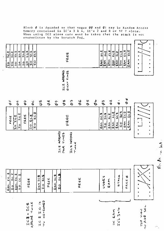
Block 0 is decoded so that pages 00 and 01 may be Random AccessMemory contained in IC's 3 & 4, IC's 2 and 8 or IC 2 alone.When using IC2 alone care must be taken that the stack is notoverwritten by the Scratch Pad.
if0H
0H
0
a0H
o>0H
0
N0H
0H
oi0V*
0H
0H
0H of
Ja*
(V)
<rot
CO
0HL
Si
cJ\JH
1 £ f
vs in
U-
OJv)
H0H
UI (
0H
UiUlcC
nJOH0H
0H
0H
SIcJ
0H
0H
0H
cu
1
oi0H1
CW Jf(0H
cu0H
1
oi0H
H H
0H
CPoH
I<t
(00
0H
31H ,9
^4T
0 °
MJ
tt
4
MORNPUTER Acorn Computers Limited, 4a Market Hill. Cambridge CB2 3NJ, England. Telephone 0223 312772
PARTS LIST FOR ACORN MICROCOMPUTER
P.C.B.
ICI
IC2
IC3
IC4
IC5
IC6
IC7
IC8
IC9
IC10
ICI 1
ICI 2
IC 1 3 ...
XTAL
RESET SWITCH "\
IRQ SWITCH £
NM1 SWITCrl J
EUROCONNECTOR
Nut and screw
16 pin socket
Acorn Computers Ltd. pt no 200,000
6502 Micro Processor
8154 RAM/10
2 114 RAM
2 114 RAM
74S571 Blue ROM
74S571 Yellow ROM
and 40 pin socket
and 40 pin socket
and 18 pin socket
and 18 pin socket
and 16 pin socket
and 16 pin socket
2516 EPROM. NOT SUPPLIED IN KIT but24 pin socke t is.
8154 RAM/10. NOT SUPPLIED IN KIT but40 pin socket i s.
74LS20
74LS139
74LS04
74LS00
LM340-T5
1MHz CRYSTAL
.... and 14 pin socket
.... and 16 pin socket
.... and 14 pin socket
.... and 14 pin socket
5v REGULATOR
SWITCH TYPE D6. ONLY ONE SWITCH SUPPLIED IN KIT
32 way PLUG. NOT SUPPLIED IN KIT
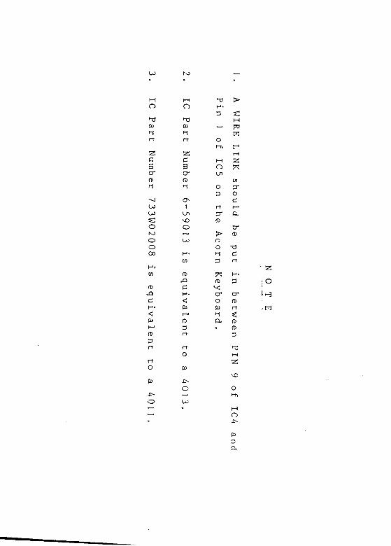
for IC13.
for Address links.
ISSUE 1. 23.02.79. 200,000/P J of
16
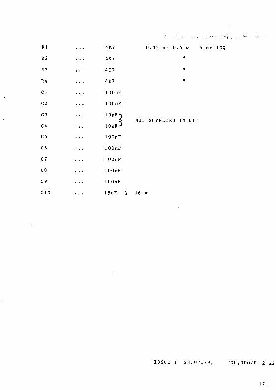
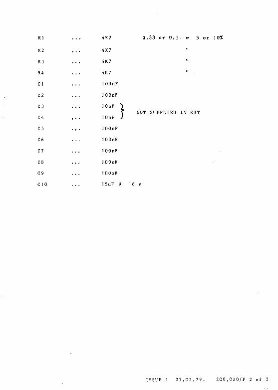
Rl ... 4K7 0.33 or 0.5 w 5 or 10%
R2 ... 4K7 lf
R3 ... 4K7 "
R4 ... 4K7
Cl ... JOOnF
C2 ... lOOnF
C3 ... J OnF*)
C4 ... 10nF-
C5 ... JOOnF
C6 , , , ]OOnF
C7 ... lOOnF
C8 ... 1OOnF
C9 ... JOOnF
CIO ... J 5uF @ J 6 v
I NOT SUPPLIED IN KIT? J
ISSUE J 23.02.79. 200,000/P 2 of
17 .
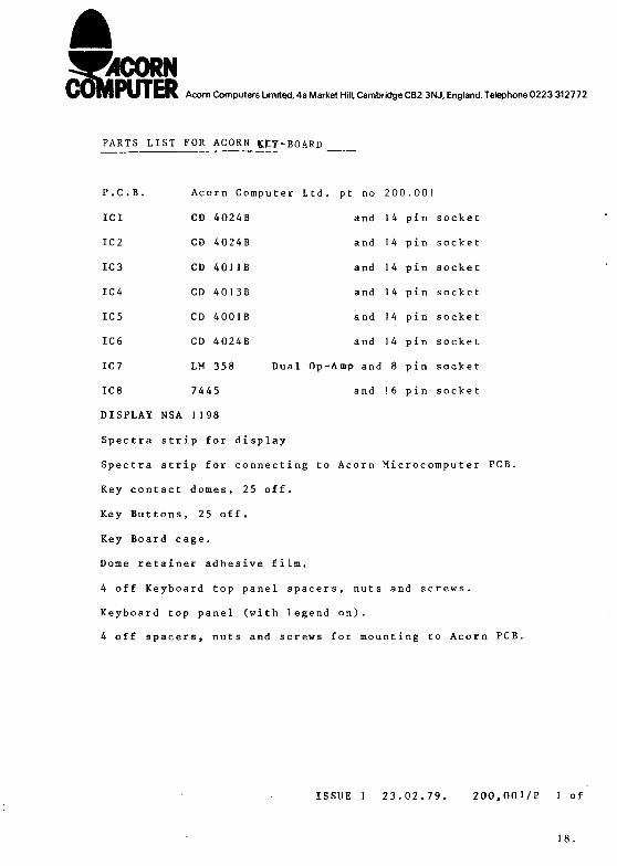
WORNPUTER Acorn Computers Limited, 4a Market Hill. Cambridge CB2 3NJ, England. Telephone 0223 312772
PARTS LIST FOR ACORN KEY-BOARD
and 14 pin socket
and 14 pin socket
and 14 pin socket
and 14 pin socket
and 14 pin socket
and 14 pin socke t
p and 8 pin socket
and 16 pin socke t
DISPLAY NSA 1J98
Spectra strip for display
Spectra strip for connecting to Acorn Microcomputer PCB.
Key contact domes, 25 off.
Key Buttons, 25 off.
Key Board cage.
Dome retainer adhesive film.
4 off Keyboard top panel spacers, nuts and screws.
Keyboard top panel (with legend on).
4 off spacers, nuts and screws for mounting to Acorn PCB.
P.C.B.
ICI
IC2
IC3
IC4
IC5
IC6
IC7
IC8
Acorn Computer Ltd. j
CD 4024B
CD 4024B
CD 40JIB
CD 4013B
CD 4001B
CD 4024B
LM 358 Dual Op-Ai
7445
ISSUE 1 23.02.79. 200,001/P 1 of
18.
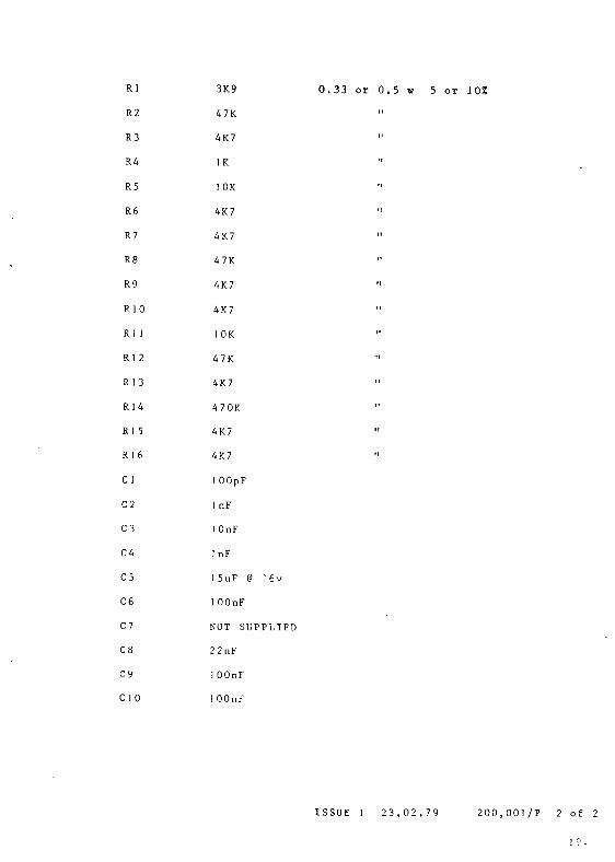
Rl
R2
R3
R4
R5
R6
R7
R8
R9
RIO
R] 1
Rl 2
R13
R14
R15
R16
C 1
C2
C3
C4
C5
C6
C7
C8
C9
C 1 0
3K9
47K
4K7
IK
1OK
4K7
4K7
47K
4K7
4K7
1 OK
47K
4K7
47OK
4K7
4K7
lOOpF
1 nF
1 OnF
1 nF
15uF @ I6v
lOOnF
NOT SUPPLIED
22nF
1 OOnF
1 OOnF
0 . 3 3 o r 0 . 5 w 5 o r J0%
ISSUE 1 2 3 , 0 2 , 7 9 2 0 0 , 0 0 ] / P 2 o f 2
1 °.
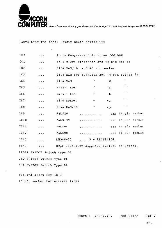
WORNV V m i U I C K Acorn Computers Limited, 4a Market Hill, Cambridge CB2 3NJ, England. Telephone 0223 312772
PARTS LIST FOR ACORN SINGLE BOARD CONTROLLER
PCB ... Acorn Computers Ltd. pt no 200,000
ICI ... 6502 Micro Processor and 4 0. pin socket
IC2 ... 8154 RAM/10 and 40 pin socket
IC3 ... 2114 RAM NOT SUPPLIED BUT 18 pin socket is.
IC4 ... 2114 RAM " 18
IC5 ... 74S571 ROM " 16
IC6 ... 74S571 ROM " 16
IC7 ... 2516 EPROM. " 94
IC8 ... 8154 RAM/10 " 40
IC9 ... 74LS20 and 14 pin socket
IC 1 0 ... 74LS139 and 16 pin socket
IC11 ... 74LS04 and 14 pin socket
IC 1 2 ... 74LS00 and 14 pin socket
IC13 ... LM340-T5 ... 5 v REGULATOR
XTAL ... 82pF capacitor supplied instead of Crystal
RESET SWITCH Switch type D6
IRQ SWITCH Switch type D6
NMI SWITCH Switch Type D6
Nut and screw for IC13
16 pin socket for Address links
ISSUE 1 23.02.79. 200,0 10/P 1 of 2
20.
Rl
R2
R3
R4
Cl
C2
C3
C4
C5
C6
C7
C8
C9
CJO
4K7
4K7
4K7
4K7
JOOnF
JOOnF
J OnF
J OnF
JOOnF
J OOnF
J OOnF
JOOnF
JOOnF
J5uF i
G.33 or 0.5 5 or 10%
NOT SUPPLIED IN KIT
J6 v
ISSUE J 23.02.79. 200,OJO/P 2 of 2
MO
03r~{
r t
C
crft)>-$
- • J
U )U3
oK3
OO0 0
w"
fD
c
<03I—i
M
n
03
r t
^
C3crfDt*i
a^1
U i
o-—Uo
H *
cn
fD
r j
<
03I—1
fD
D
•x)
, .
ol-h
n
o
r f
fD
J>oo>-{
fD
O03Y~{
p.
>
r1
2J
cn
O
ci—'
CL
crfD
r t
fDr t
^fDfD
i O
: W
TJ
o
-F-O
o
03
o
M
vD
Ol-h
O
03D