Embed Size (px)
Citation preview
1
ACOUSTICALLY INDUCED AND FLOW INDUCED VIBRATION: LITTLE-KNOWN FAILURE MODES NOW ADDRESSED IN
AS/NZS 2885.1:2018 S. J. Monaghan Lead Vibration Engineer, Enscope (A Quanta Services Company), Brisbane,
Australia. Contact [email protected] R. J. Swindell Vibration Engineering Lead, Vibration Dynamics and Noise, Wood PLC,
Southampton, UK. Contact [email protected] E. L. Metcalfe Principal Consultant, Metcalfe Engineering, Melbourne, Australia. Contact
[email protected] 1. INTRODUCTION During pipeline depressurisation and repressurisation operations, high gas velocities and mass flow rates induce vibration and cyclic stressing, which can result in station piping fatigue damage and failure. The same can occur during station pressurisation events, if the process conditions are such that high vibration levels are experienced. A recent major gas pipeline design investigation discovered two types of vibration concerns which would manifest during both pipeline depressurisation and repressurisation operations, and to a lesser extent during facility and pig trap pressurisation operations. Until now, these forms of vibration have not been widely understood nor considered by Designers within the Australian pipeline industry. The vibration types of concern are Acoustically Induced Vibration (AIV) and Flow Induced Vibration (FIV). Achieving a safe rectification of the design without a full shutdown of the entire pipeline system required significant data collection, analysis, simulation modelling, and extensive re-design effort. This paper will describe what was essentially a major research project, with safety and system integrity as ultimate objectives. The discovery of AIV and FIV issues on this operating pipeline, together with knowledge gained through the design and engineering process to mitigate these forms of vibration, resulted in recommended changes to AS 2885.1-2012 [1]. These changes, led by the authors, appear in the latest release of AS/NZS 2885.1:2018 [2], and provide guidance to pipeline Designers to avoid AIV and FIV problems. This paper explains the causes and nature of both types of piping vibration and explains why certain changes were made to AS 2885.1-2012 [1]. The changes are discussed, with concluding advice as to how these changes should be applied by pipeline Designers, and what pipeline Owners and Operators should do for their operating assets. 2. PIPELINE OPERATIONS AND PATHWAYS USED Typical Pipeline Design and Operation This paper relates to high-pressure steel gas transmission pipelines. These may be of varying length, diameter and design pressure, but most often:
• Have scraper launchers and receivers at the ends and possibly at intermediate points;
• Are divided into sections by isolation valves or Main Line Valves (MLVs) for maintenance or emergency response; and
2
• Each pipeline section is provided with a means of manually depressurising to atmosphere through a local or remote vent, as well as subsequent purging and repressurisation.
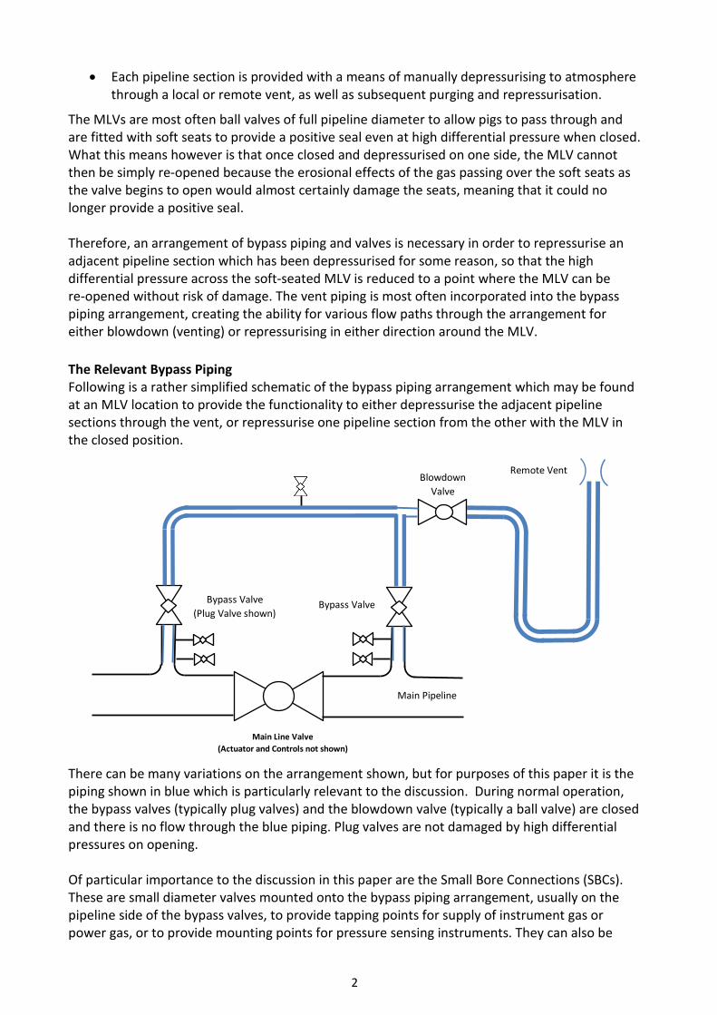
The MLVs are most often ball valves of full pipeline diameter to allow pigs to pass through and are fitted with soft seats to provide a positive seal even at high differential pressure when closed. What this means however is that once closed and depressurised on one side, the MLV cannot then be simply re-opened because the erosional effects of the gas passing over the soft seats as the valve begins to open would almost certainly damage the seats, meaning that it could no longer provide a positive seal. Therefore, an arrangement of bypass piping and valves is necessary in order to repressurise an adjacent pipeline section which has been depressurised for some reason, so that the high differential pressure across the soft-seated MLV is reduced to a point where the MLV can be re-opened without risk of damage. The vent piping is most often incorporated into the bypass piping arrangement, creating the ability for various flow paths through the arrangement for either blowdown (venting) or repressurising in either direction around the MLV. The Relevant Bypass Piping Following is a rather simplified schematic of the bypass piping arrangement which may be found at an MLV location to provide the functionality to either depressurise the adjacent pipeline sections through the vent, or repressurise one pipeline section from the other with the MLV in the closed position.
There can be many variations on the arrangement shown, but for purposes of this paper it is the piping shown in blue which is particularly relevant to the discussion. During normal operation, the bypass valves (typically plug valves) and the blowdown valve (typically a ball valve) are closed and there is no flow through the blue piping. Plug valves are not damaged by high differential pressures on opening. Of particular importance to the discussion in this paper are the Small Bore Connections (SBCs). These are small diameter valves mounted onto the bypass piping arrangement, usually on the pipeline side of the bypass valves, to provide tapping points for supply of instrument gas or power gas, or to provide mounting points for pressure sensing instruments. They can also be
Bypass Valve(Plug Valve shown)
Blowdown Valve
Remote Vent
Main Line Valve(Actuator and Controls not shown)
Bypass Valve
Main Pipeline
3
used as a local vent point to confirm that there is no trapped pressure between two closed bypass valves. The manner in which these SBCs are welded to the bypass piping is extremely important in determination of the integrity of the piping arrangement when used for the intended purposes of blowdown or repressurisation. A normally operating pipeline, even at high pressure, displays very low levels of vibration due to controlled mass flow rates and gas velocities. It is during abnormal operating conditions or Unusual Operations involving the bypass piping that the design integrity of the piping becomes critical. Given some level of vibration is expected during bypass operations, and because the number of operations and the duration of each operation of the bypass piping over the life of the asset cannot be known with certainty, bypass piping should be designed for an infinite fatigue life. Bypass piping is most often designed to a robust process piping specification such as AS 4041-2006 [3] or ASME B31.3-2018 [4]. Fatigue damage assessments should be performed to BS 7608:2014 with Addendum A1:2015 [5]. Unusual Operations – What are they? Unusual Operations are those which are not part of normal steady state pipeline system operation. Section 4.5 of AS/NZS 2885.1:2018 [2] lists Unusual Operations as pipeline activities including the initial fill and pressurisation, depressurisation and subsequent purging and repressurisation. These same activities can also be performed around isolation valves within pipeline stations, pipeline assemblies and pig traps. Typically a plug valve is used for the pressure let-down, but the same principles apply for other devices such as restriction orifice plates or any other gas choke points. Relative to normal operations, these Unusual Operations generally involve very high pressure differentials, very high gas flow rates, and generation of very low temperatures, often described as ‘severe service’. The high mass flow rates and gas velocities are often encountered due to an operational incentive to vent gas or return a pipeline to service within the shortest timeframe possible. Unusual Operations Generate Vibration and Low Temperature Unusual Operations can generate high vibration and low temperatures, as the potential energy of the high pressure gas source is converted into acoustic energy and kinetic energy, with associated Joule-Thomson (JT) cooling effects.
• Acoustic energy, which is the sound power generated at the pressure let-down source, creates AIV with localised high frequency pipe wall vibration and dynamic stresses;
• Kinetic energy, which is the gas turbulent energy due to flow disturbances, creates FIV with low to mid-frequency piping and SBC vibration and dynamic stresses; and,
• Low temperature, due to JT cooling, occurs when a gas expands on release from a high pressure to a low pressure, causing rapid cooling of piping and components resulting in expansion/contraction of piping with induced static stresses.
During Unusual Operations, both the piping and support arrangement must remain sufficiently flexible to accommodate thermal movement and static stress, but sufficiently stiff to minimise vibration and dynamic stress. These conflicting requirements can represent a challenge for the pipeline Designer. Further, welded joints must exhibit sufficient fracture toughness in order for Designers to be able to rely on fatigue damage calculations and predict fatigue life with confidence [5], which is an aspect requiring some interaction with the procurement and construction Contractor (e.g. Charpy impact temperatures for weld procedure qualifications).
4
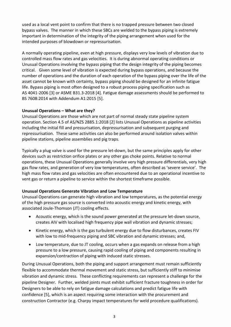
3. VIBRATION MECHANISMS AND HOW THEY MANIFEST High pressure gas let-down facilities can experience several forms of vibration excitation as summarised in the table below; these include AIV and FIV, of which for FIV there are three main sub-types (flow induced turbulence, flow induced pulsation, and jet impingement induced vibration). Each has its own characteristics in terms of the frequency distribution of energy (e.g. broadband – where energy is generated over a range of frequencies, or discrete frequency – where energy is generated at a single frequency (and possibly harmonics thereof)) and the typical frequency range over which energy is input to the piping system.
Mechanism Description Energy/Power Parameter
Typical Frequency of
Excitation
Acoustically Induced
Vibration (AIV)
Broadband acoustic energy generated by choked flow and high frequency turbulent mixing due to a combination of high differential pressure and high mass flow rate at a pressure reducing device
Sound power level 500-2000 Hz
Flow Induced Turbulence
(FIT)
Broadband turbulent energy generated by flow discontinuities in the piping system (elbows, valves, reducers)
Fluid kinetic energy (ρv2) <100 Hz
Flow Induced Pulsation (FIP)
Discrete frequency energy generated by excitation of local deadleg sidebranch acoustic resonances by flow past the open mouth of the deadleg
Fluid kinetic energy (ρv2) 5-500 Hz
Jet Impingement
Induced Vibration (JIV)
Discrete frequency energy generated by high Mach number flow from a side-branch into a header
Fluid kinetic energy (ρv2) 500-2000 Hz
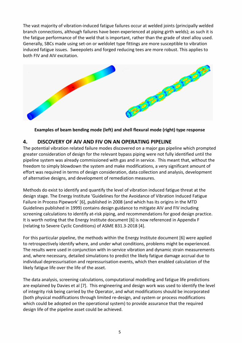
The key fluid parameters associated with AIV are the pressure drop and the mass flow rate across the pressure reducing device, which determine the source sound power level generated by the pressure let down; an internal sound power level of 180 dB re 1x10-12 Watts (which equates to 1 MW of acoustic energy) can easily be achieved with a high differential pressure and mass flow rate. For FIV mechanisms, the key parameter is the fluid kinetic energy (which is proportional to the square of the velocity of the process fluid); doubling the fluid velocity therefore results in a four times increase in the fluid energy assuming the fluid density remains constant. At lower frequencies the piping response is governed by the beam bending type modes of the piping system with unsupported SBCs typically responding in their fundamental cantilever mode. However, at higher frequencies, SBCs may respond at a higher order cantilever mode, and the parent pipe response will tend to be dominated by the shell flexural modes of the pipe wall (which, as an example, will occur at around 300 Hz and above for a DN450 Schedule 40 pipe). The two forms of parent pipe response are illustrated below.
5
The vast majority of vibration-induced fatigue failures occur at welded joints (principally welded branch connections, although failures have been experienced at piping girth welds); as such it is the fatigue performance of the weld that is important, rather than the grade of steel alloy used. Generally, SBCs made using set-on or weldolet type fittings are more susceptible to vibration induced fatigue issues. Sweepolets and forged reducing tees are more robust. This applies to both FIV and AIV excitation.
Examples of beam bending mode (left) and shell flexural mode (right) type response 4. DISCOVERY OF AIV AND FIV ON AN OPERATING PIPELINE The potential vibration related failure modes discovered on a major gas pipeline which prompted greater consideration of design for the relevant bypass piping were not fully identified until the pipeline system was already commissioned with gas and in service. This meant that, without the freedom to simply blowdown the system and make modifications, a very significant amount of effort was required in terms of design consideration, data collection and analysis, development of alternative designs, and development of remediation measures. Methods do exist to identify and quantify the level of vibration induced fatigue threat at the design stage. The Energy Institute ‘Guidelines for the Avoidance of Vibration Induced Fatigue Failure in Process Pipework’ [6], published in 2008 (and which has its origins in the MTD Guidelines published in 1999) contains design guidance to mitigate AIV and FIV including screening calculations to identify at-risk piping, and recommendations for good design practice. It is worth noting that the Energy Institute document [6] is now referenced in Appendix F (relating to Severe Cyclic Conditions) of ASME B31.3-2018 [4]. For this particular pipeline, the methods within the Energy Institute document [6] were applied to retrospectively identify where, and under what conditions, problems might be experienced. The results were used in conjunction with in-service vibration and dynamic strain measurements and, where necessary, detailed simulations to predict the likely fatigue damage accrual due to individual depressurisation and repressurisation events, which then enabled calculation of the likely fatigue life over the life of the asset. The data analysis, screening calculations, computational modelling and fatigue life predictions are explained by Davies et al [7]. This engineering and design work was used to identify the level of integrity risk being carried by the Operator, and what modifications should be incorporated (both physical modifications through limited re-design, and system or process modifications which could be adopted on the operational system) to provide assurance that the required design life of the pipeline asset could be achieved.
6
5. WHY IS AIV & FIV LITTLE-KNOWN IN AUSTRALIAN PIPELINES? Whilst AIV and FIV failure modes have been relatively well-considered in the design of gas processing plant flare systems and vent systems for many years, knowledge of AIV and FIV in pipeline systems and its application to pipeline design has not been well established at all. Venting and flaring in gas processing facilities is normal practice. These pressure relief and blowdown systems operate fairly frequently, and therefore repeated failures of a similar nature have been carefully investigated; early work in this area was published by CONCAWE in 1985 [8]. For pipelines, the frequency of events involving the use of bypass piping for depressurisation or repressurisation is low, meaning that any historical piping failures may not have been properly investigated, and therefore may not have been attributed to AIV or FIV if those conditions were present. Even experienced Designers of pipelines in Australia when contacted by the authors acknowledged that they were not familiar with either AIV or FIV as potential failure modes for bypass piping. The authors of this paper have attempted to determine why this might be the case and have identified some possible explanations. Australian versus International Design Expertise The design practices of Australian pipeline systems differ from those of most overseas gas transmission pipelines to some extent, and this partly explains why AIV and FIV as a failure mode in the bypass piping arrangements may have first been identified here in Australia. Internationally:
• Most international gas transmission pipeline systems are designed to Class 600, and although some have been built, Class 900 designs are not common internationally.
• Although there are many larger diameter (“big-inch”) gas transmission pipelines overseas, they are for the most part designed to ASME B31.8-2018 [9] with maximum 20 mile (about 30 km) spacings between MLV sites. The resultant limitation on total section volumes has not created the incentive to design with very large bypass piping diameters to limit blowdown and repressurisation durations.
• Bypass piping arrangements on most international pipelines are usually designed to ASME B31.3-2018 [4], a process piping specification which delivers an inherently robust piping design.
• Local vent stacks, with the blowdown valve immediately upstream of the vent tip, are the typical design internationally, for which most of the JT cooling on blowdown is created in the atmosphere and not in the piping. The added benefit here is that there is little to no piping subjected to AIV and control of FIV is typically limited to the vent stack itself. Remote blowdowns, with separation between the blowdown valve and vent stack, are more common in Australia.
Why is Australia different?
Pipeline systems in Australia are often required to deliver relatively small gas capacities over very long distances compared to international pipeline systems, and there has been continuing pressure to reduce the cost of pipeline system construction:
7
• Australian pipeline Designers have designed several pipeline systems with design pressures in the Class 900 category to improve transmission efficiency and reduce steel costs.
• Pipeline system design experience in Australia has primarily involved small to mid-diameter pipelines, with little local experience on “big-inch” pipelines DN900 (36 inch) and above, though these larger diameters have now been locally constructed.
• To reduce cost, MLV spacings on Australian pipelines have typically been maximised in remote (R1 classification) areas, however historically in combination with the smaller mainline diameters, section volumes have remained low and the incentive to use large diameter bypass piping to reduce the duration of Unusual Operations has not been present.
• Bypass piping specifications have been mostly in accordance with ASME B31.3-2018 [4] or AS 4041-2006 [3], though examples exist of designs experimenting with high-strength linepipe for bypass piping service and design to AS 2885.1-2012 [1].
• Health and Safety concerns have driven most Australian pipeline systems designed in the past couple of decades to implement remote vent stack designs instead of the simpler vertical vents. Consequently, the Designer must consider AIV, FIV and JT cooling in the vent piping as well.
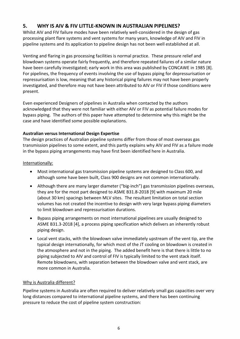
The Published AIV Failure Data Recent literature reporting AIV failures publicly [10] indicates that:
• AIV failures are relatively rare (although not unknown) in piping of less than DN250 (10 inch) diameter; and,
• Piping which has suffered AIV failure almost always has a D/t ratio (diameter to wall thickness) of greater than 20.
Within the diameter range potentially of interest for bypass piping, say DN100 through DN500, process piping specifications prepared by Designers for operation at Class 600 or 900 pressures (based on design codes such as AS 4041-2006 [3] or ASME B31.3-2018 [4] and using standard dimension tables for piping to ASME B36.10M-2018 [11]) may result in D/t ratios of greater than 20. A ratio greater than 20 certainly does not provide any definitive assessment criteria for the likelihood of AIV failure, however does represent potential pre-conditions for the AIV failure mode when designing piping arrangements for high pressure gas service. It is important to understand that many existing design codes do not explicitly consider AIV (or FIV), though this guidance relating to a threshold D/t ratio of 20 now appears in AS/NZS 2885.1:2018 [2], with other guidance such as the Energy Institute document [6] able to identify whether the selected D/t ratio is adequate based on the intended service conditions. Recent Australian Design Developments Pipeline design innovations in Australia in pursuit of lower costs of construction have included several design “step-outs”, which are incremental departures from normal design practice. In
AIV failure at a reinforcement pad weld
8
this manner, the pipeline industry has progressively evolved, unknowingly leading to higher susceptibility to AIV and FIV:
• We now commonly design for Class 900 operating pressures, for which higher-strength linepipe specifications are appropriate. Greater pressure differentials result during Unusual Operations, exacerbating both vibration and JT cooling issues;
• We have examples of high strength line pipe being used for station bypass piping, despite the D/t ratio being within the range of that reported with AIV failures;
• We have constructed longer, larger diameter pipelines with significant MLV spacing (large section volumes), and consequently design with even larger diameter bypass piping to minimise blowdown and repressurisation times; and,
• We have examples of lower cost options such as forged weldolet pipe fittings rather than forged reducing tees for SBC design, with these often being flexible and with the (heavyweight) isolation valve(s) unsupported.
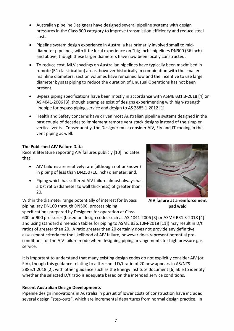
Pre-Conditions for Potential AIV and FIV Failure The following diagram illustrates four factors or pre-conditions, also referred to in this paper as design “step-outs”, which may contribute to an increased likelihood of an AIV or FIV failure.
It is the authors experience that:
• Any one of these design step-outs, occurring in isolation, may be quite acceptable and not lead to failure;
• Any two or more of these design step-outs, coupled together, may cause a problem; and,
• All four design step-outs, occurring concurrently, will likely be a problem resulting in an AIV/FIV failure.
It is apparent that over recent years, Australian pipeline Designers may have unwittingly been edging closer to the AIV/FIV failure issue, often in pursuit of lower costs, but without realising the dangers, because AIV/FIV failure has not previously been recognised in the bypass piping arrangements of pipeline systems designed either here or internationally.
High Pressure PipelinesClass 900 Systems
Larger Differential PressuresHigher Mass Flow Rates
High Strength LinepipeThin-Walled Piping - Flexible and
Often Not Suitable in Bypass Service (Unusual Operations)
Small Bore ConnectionsPoorly DesignedPoorly Located
Poorly Supported
Larger Pipeline VolumesIncreased Mainline Valve Spacing
Increased Pipeline DiameterLonger Duration to Re-/De-Pressurise
If each of these overlap... Likely AIV / FIV Problem
9
6. HOW PROJECT FINDINGS LED TO CHANGES TO AS 2885.1-2012 The authors of this paper were involved in a recent major gas pipeline design investigation which identified several potential failure modes associated with AIV/FIV and low temperature in bypass piping, and that experience has in part prompted the changes that appear within AS/NZS 2885.1:2018 [2]. The authors realised that the particular failure modes identified:
• Presented a significant risk in terms of piping design integrity and process safety;
• Were a consequence of concurrent step-outs in pipeline design; however,
• Were not currently well understood in Australian pipeline design.
We felt obligated by a duty of care to the industry, based on concern that other Designers and Operators should be made aware of the potential failure modes, so we contacted and provided input via the ME-038 Committee and assisted with wording for the changes. 7. AS/NZS 2885.1:2018 – WHAT’S CHANGED? The requirement to analyse low temperature excursions is not new, but the requirement to specifically address AIV and FIV is an addition to the recently issued AS/NZS 2885.1:2018 [2]. Previous Guidance Guidance in relation to design for low temperature excursions has been in the Standard for many years, and is relatively well understood, although still somewhat subject to misinterpretation in relation to permissible piping stresses coincident with low temperature excursions. Further, during permitted low temperature excursions, fatigue damage predictions only remain valid if sufficient fracture toughness can be demonstrated, or vibration levels are sufficiently controlled. Guidance on design for vibration in severe service has also been in the Standard for many years, just not explicitly spelled out, and the Standard has relied heavily on experience and competence of Designers to avoid misinterpretation of the Standard. Updated Guidance The 2018 release of AS/NZS 2885.1 introduced AIV and FIV as explicit loads requiring assessment in terms of piping fatigue. These loads occur during Unusual Operations, however mitigating the vibration conditions by restricting flow rates can exacerbate low temperature problems, as well as leading to other operational constraints. Low temperature, AIV and FIV can individually and cumulatively create significant piping stresses (both static and dynamic) and now are required by the Standard to be considered. The failure modes identified were added as a matter to be considered by pipeline Designers. Existing clauses and normative guidance which intended to prevent poor design from being implemented were strengthened so as to clarify intent. Designers are encouraged to seek expert advice where appropriate. Specific Changes Within the 2018 release of AS/NZS 2885.1, the following are changes related to AIV and FIV:
• Foreword (k) indicates the potential for AIV and FIV is recognised as a design condition.
10
• Foreword (C) indicates Appendix J, Fatigue has undergone major change to include the addition of an important qualification on the validity limits for the simplified screening criterion and recognition of both AIV and FIV.
• Clause 4.8.2 states the isolation plan shall define, in item (iv), that segments of the pipeline for which depressurising facilities are required, AIV and FIV assessments are included in terms of implication with segment length, stored volume, depressurisation time and repressurisation time.
• Clause 4.8.3 states the selection of spacing between isolation valves shall also take into account the design of blowdown and bypass piping and the time required for blowdown and repressurisation of each segment of the pipeline, and the implications for AIV and FIV in the blowdown or bypass piping or elsewhere.
• Clause 5.9.1 Note 2 states that a pipeline assembly, or a part of it such as bypass piping, should be in accordance with Clause 5.9.1(ii) if during normal or abnormal operation it may be subjected to severe service involving either low temperature, or high differential pressure and high flow that may promote AIV or FIV. Clause 5.9.1(ii) relates to station piping, so the requirement here is that a station piping design code should be used if bypass piping may be subject to AIV or FIV.
This same clause states such vibration may lead to fatigue failures at weld connections such as small-bore branches and as such appropriate analysis should be undertaken to identify AIV and FIV to inform design measures to mitigate it, with a reference to Appendix J for further information.
• Clause 6.3.2 states fatigue failures may occur as a result of AIV or FIV under process conditions of high mass flow and significant pressure drop such as may occur during some routine operations and particularly during unusual operations such as depressurisation and repressurisation. The same clause states where such conditions are possible the design shall be appropriate for the conditions and the design life, with a reference to Appendix J for further information.
• Appendix J relates to fatigue. Section J1(c) Rapid fatigue due to AIV or FIV, i.e. at stations and pipeline assemblies (see Clause 5.9.1 and Paragraph J4) is now included as a source of fatigue loading that should be considered during the design phase.
• Section J3 relates solely to AIV and FIV, providing definitions of AIV and FIV, its likely sources, vibration transmission paths, typical responses and failure locations, and design solutions for mitigation. Importantly, the Energy Institute document ‘Guidelines for the Avoidance of Vibration Induced Fatigue Failure in Process Pipework’ [6] is referred to as design guidance for AIV and FIV. This document should be consulted in relation to design of surface facilities piping subjected to high flows such as during unusual operations.
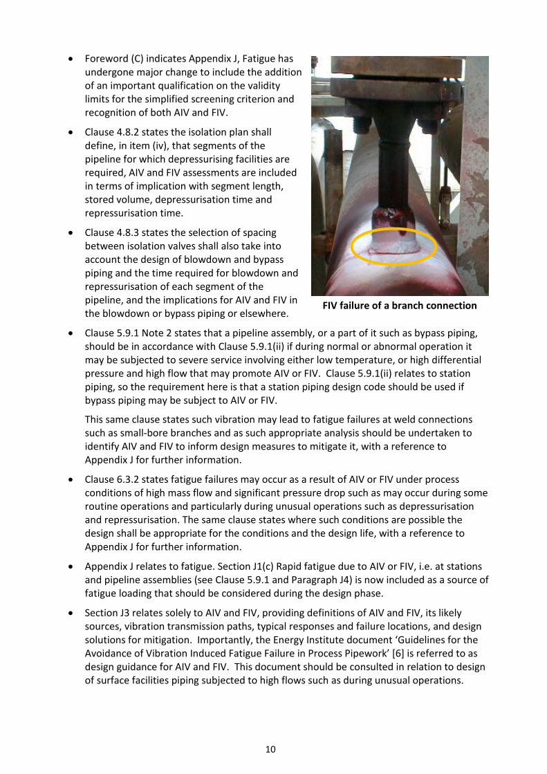
FIV failure of a branch connection
11
There is also a recommendation to consider instrumented field testing (incorporating vibration and/or dynamic strain measurement) under load conditions during commissioning for assurance of piping design integrity.
This same section also states AIV and FIV should be considered in relation to piping systems, or in the event of modification or addition to these systems.
8. AS/NZS 2885.1:2018 – HOW DO THE CHANGES IMPACT INDUSTRY? Impact to Designers and Industry The AIV and FIV requirements included in AS/NZS 2885.1:2018 [2] must be considered and applied by Designers to both new designs and when making modifications to existing assets (both physical changes or changes to process conditions). Designers must now consider the implications of AIV and FIV in terms of:
• The selected pipeline segment stored volume and MAOP, which together impact depressurisation time and repressurisation time;
• The piping design code that should be applied and the selection, configuration and layout of blowdown and bypass piping, and the combined low temperature effects during Unusual Operations;
• The selection of piping and its diameter to thickness (D/t) ratio, and types of fittings, particularly around SBCs, in terms of location, configuration, stiffness and low temperature toughness;
• Design guidance resulting from application of the screening within the Energy Institute document [6], which may suggest a revised design necessitating further screening;
• Whether service conditions are so severe that expert advice is essential; and,
• Whether design compliance is marginal warranting instrumented field testing during commissioning.
Although not mandatory to retrospectively apply the AIV and FIV related changes to existing operating assets, the authors recommend as good practice Owners and Operators consider the changes and at a minimum apply the Energy Institute document [6] guidelines screening. Avoidance of AIV and FIV by Design Clearly the most appropriate time at which to avoid potential for AIV and FIV induced failures is at the design stage. Further to design requirements listed above, several other design parameters should be considered concurrently, such as:
• If the MAOP combined with pressurisation rate, for both repressurisation and depressurisation, creates low temperature excursion conditions coincident with vibration such that fatigue damage guidance (e.g. BS 7608:2014 + A1:2015 [5]) cannot be directly applied?
• In selecting a larger bypass piping diameter to speed up repressurisation time, reduce local gas velocity and move cold temperatures downstream (i.e. the Fast Fill approach), is the larger diameter more at risk of creating an AIV condition?
• When increasing an orifice bore to shorten the blowdown duration, does this promote AIV or FIV conditions, or increase noise impact on nearby operating personnel (occupational) or landowners (environmental) or exceed environmental authority limits?
12
• Can SBCs be eliminated, though if not, are they well designed and supported to ensure sufficient dynamic stiffness and suitable mechanical natural frequencies based on all expected operating frequencies and conditions (e.g. acoustic deadleg pulsation)?
• Have all potential blowdown and repressurisation operating scenarios and valving configurations been sufficiently reviewed during a Hazard and Operability Study (HAZOP) to ensure risks and operating errors are sufficiently mitigated or controlled?
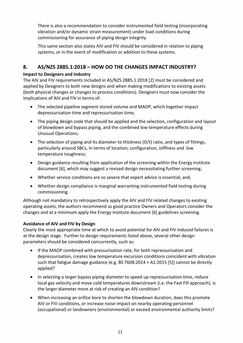
This FIV failure of a welded gusset demonstrates bracing is not always the solution, and must
be designed and installed correctly for the service conditions
If the bypass piping design is sufficiently robust, during repressurisation events field operators can minimise the extent and duration of JT cooling in the downstream bypass piping and the buried pipeline by rapidly and fully opening the bypass valves. The change in pressure profile within the pipeline using this “fast fill” approach has the effect of spreading the JT cooling impacts over a greater length of piping and buried pipeline and allows ground temperature to partially offset the cooling of the steel over this greater distance. However, this procedure is only feasible if the bypass piping arrangement is designed to withstand the vibration loading of the high mass flow rates. Accurate modelling of the JT cooling of the gas and heat transfer from the ground is also required. Expert advice should be sought if this approach is considered. Assessment of Existing Designs and Operating Assets If during Unusual Operations piping vibration has been identified, or if a prudent Operator retrospectively applies the AIV and FIV guidance within AS/NZS 2885.1:2018 [2], then the Energy Institute document [6] and design requirements listed above should be considered in parallel. The difference when assessing existing designs versus new designs is not the application of this guidance, instead it is the options available should an AIV or FIV concern be found. Redesign probably won’t be the first consideration for an existing, operating asset. That is, redesigning to treat the source of vibration, be it the process conditions or the piping configuration, won’t typically be available as an option. Instead, treating the response of the system, such as by stiffening a SBC with suitable bracing or adding additional clamps to piping runs, may be the first
13
consideration. It is always preferred to treat the source, but with existing designs, we often have to settle for mitigating the response. A consideration for all assets, whether new designs or existing designs, is design life. Where piping is expected to have some amount of vibration, such as bypass piping for Unusual Operations, an infinite fatigue life is recommended, as this avoids having to predict the number of Unusual Operations over the planned life of the asset. This isn’t an option though for existing designs, so when fatigue predictions are employed, careful attention must be given to historical operations and the predicted fatigue damage accrued to date. This historical damage is then combined with predicted future fatigue damage to determine the probability of fatigue failure within the design life of the asset. Avoidance of AIV and FIV by Procedure In situations where some potential for AIV or FIV induced failure is identified, it may be possible to mitigate the risk via procedural means. This however typically adds procedural complexity, and it is well known in industry that strict compliance with special procedures cannot always be assured. In these circumstances, to avoid operating errors, mechanical isolations or valve interlocks are sometimes introduced, certainly adding both cost and complexity. Other solutions available include monitoring of consumed fatigue life via detailed predictive tools, which rely on both accurate prediction of vibration levels causing fatigue damage as well as diligent record keeping by Operations personnel after each event. These tools are used to predict the fatigue damage accrued to date, and the number of future events permissible before reaching a fatigue damage accrual limit. Although these types of predictive tools do have their place, they are best reserved for existing assets where infinite fatigue life cannot be assured. 9. SUMMARY AND RECOMMENDATIONS In the opinion of the authors, it is vital that Designers, Engineers and Operators openly share lessons learned in our pipeline industry so that mistakes are not repeated by others.
The changes to AS/NZS 2885.1:2018 [2] were made in the interests of ensuring that others are made aware of these potential failure modes associated with bypass piping vibration during Unusual Operations. If these changes are diligently implemented, the situation we recently faced on a major gas pipeline should not occur again in our industry.
We conclude with three simple recommendations in relation to AIV and FIV as now duly recognised design conditions:
1. AS/NZS 2885.1:2018 [2] should not be interpreted without suitable background knowledge. If you are not certain, get some expert technical assistance.
2. Never be reluctant to ask a more experienced Engineer or the ME-038 Committee for advice before changing an established design practice.
3. Innovative design step-outs must only be done with caution, and probably only one step-out at a time.
14
10. REFERENCES [1] AS 2885.1-2012, Pipelines – Gas and liquid petroleum Part 1: Design and construction, Standards Australia.
[2] AS/NZS 2885.1:2018, Pipelines – Gas and liquid petroleum Part 1: Design and construction, Standards Australia.
[3] AS 4041-2006, Pressure Piping, Standards Australia.
[4] ASME B31.3-2018, Process Piping, ASME Code for Pressure Piping, B31, The American Society of Mechanical Engineers.
[5] BS7608:2014 + A1:2015, Guide to Fatigue Design and Assessment of Steel Products, British Standards Institution.
[6] Energy Institute, Guidelines for the Avoidance of Vibration Induced Fatigue Failure in Process Pipework, 2nd Edition, 2008.
[7] Davies, M.D., Lewis, M., Monaghan, S.J., Singh, R. & Swindell, R.J., Vibration Integrity Management, Acoustic and Finite Element Analysis and In Field Measurement of Stress and Vibration on Onshore Gas Pipeline and Re/Depressurisation Facilities, Proceedings of the Institute of Acoustics, Vol. 41. Pt. 1., 2019.
[8] CONCAWE, Acoustic Fatigue in Pipes, Report No. 85/52.
[9] ASME B31.8-2018, Gas Transmission and Distribution Systems, ASME Code for Pressure Piping, B31, The American Society of Mechanical Engineers.
[10] Bruce, R. et al, Solving Acoustic-Induced Vibration Problems in the Design Stage – CSTI Acoustics, Houston, Sound and Vibration Journal, August 2013.
[11] ASME B36.10M-2018, Welded and Seamless Wrought Steel Pipe, The American Society of Mechanical Engineers.