Embed Size (px)
Citation preview
Software Version 1.3.6 8/23/2007
ACS3000 Operator’s Guide
ALX TECHNOLOGY
25A Embarcadero Cove Oakland CA, 94606
510 535-2294 www.ALXtechnology.com
PDF created with pdfFactory trial version www.pdffactory.com

8/23/2007 This document is proprietary to ALX Technology and is for customer use only ii
TABLE OF CONTENTS
GENERAL DESCRIPTION .........................................................................................1 System Components ............................................................................................1 W2000 Access Control Boards: ...........................................................................1
AIP2000 Active Interface Program: .....................................................................3 ACS3000 Access Control Program: .....................................................................4
USERS ...........................................................................................................................7 Credential Assignments .......................................................................................7
Entering new credentials: .....................................................................................8 User Access Rights: .............................................................................................9
User Time Zones : .............................................................................................11 REPORTS: ..................................................................................................................12
12HR:................................................................................................................12 REPORTS: ........................................................................................................12
REPORTS – History: .........................................................................................13 REPORTS - User:..............................................................................................14
FACILITY: ..................................................................................................................15 Status/Control: ...................................................................................................15
FTZ Assignments: .............................................................................................17 Facility Time Zones: ..........................................................................................18
Reader Tables: ...................................................................................................20 SYSTEM:.....................................................................................................................22
INDEX .........................................................................................................................28
PDF created with pdfFactory trial version www.pdffactory.com
8/23/2007 This document is proprietary to ALX Technology and is for customer use only 1
GENERAL DESCRIPTION
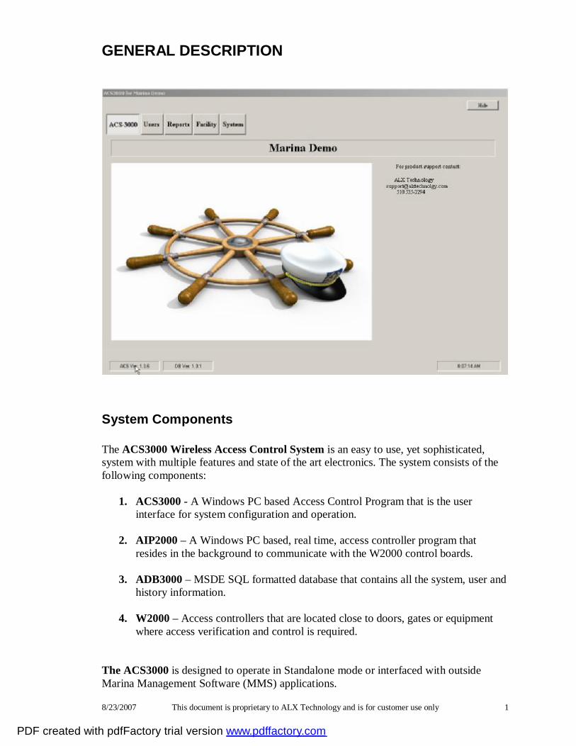
System Components The ACS3000 Wireless Access Control System is an easy to use, yet sophisticated, system with multiple features and state of the art electronics. The system consists of the following components:
1. ACS3000 - A Windows PC based Access Control Program that is the user interface for system configuration and operation.
2. AIP2000 – A Windows PC based, real time, access controller program that
resides in the background to communicate with the W2000 control boards.
3. ADB3000 – MSDE SQL formatted database that contains all the system, user and history information.
4. W2000 – Access controllers that are located close to doors, gates or equipment
where access verification and control is required. The ACS3000 is designed to operate in Standalone mode or interfaced with outside Marina Management Software (MMS) applications.
PDF created with pdfFactory trial version www.pdffactory.com
8/23/2007 This document is proprietary to ALX Technology and is for customer use only 2
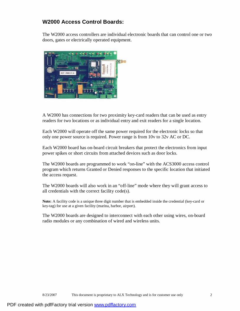
W2000 Access Control Boards: The W2000 access controllers are individual electronic boards that can control one or two doors, gates or electrically operated equipment.
A W2000 has connections for two proximity key-card readers that can be used as entry readers for two locations or as individual entry and exit readers for a single location. Each W2000 will operate off the same power required for the electronic locks so that only one power source is required. Power range is from 10v to 32v AC or DC. Each W2000 board has on-board circuit breakers that protect the electronics from input power spikes or short circuits from attached devices such as door locks. The W2000 boards are programmed to work “on-line” with the ACS3000 access control program which returns Granted or Denied responses to the specific location that initiated the access request. The W2000 boards will also work in an “off-line” mode where they will grant access to all credentials with the correct facility code(s). Note: A facility code is a unique three digit number that is embedded inside the credential (key-card or key-tag) for use at a given facility (marina, harbor, airport). The W2000 boards are designed to interconnect with each other using wires, on-board radio modules or any combination of wired and wireless units.
PDF created with pdfFactory trial version www.pdffactory.com
8/23/2007 This document is proprietary to ALX Technology and is for customer use only 3
AIP2000 Active Interface Program: The AIP2000 is a real-time Windows based program that operates in the background on a dedicated (or lightly used) PC. The AIP2000 continually monitors the selected serial communications port for access requests from any of 1 to 63 W2000 access controllers installed at the site. Upon receipt of an access request the AIP2000 will run through a series of checks in the system database to determine if access is to be granted or denied. Access will only be granted if the credential had been entered into the user database, it is “active” (not de-activated) and it is part of a User Access Rights Group that allows access at that specific location, date and time. When the AIP2000 has responded to an access request, the request and response (action) information will be saved in an access history file for subsequent access usage history reports; also referred to as the “audit trail”. The AIP2000 periodically performs a status check of all the W2000 controllers installed at the facility to determine if the boards are on-line or off-line. The status is then entered into the Status/Control screen for operator viewing. When interfaced with an outside Marina Management Software (MMS) application the AIP2000 continually looks for the receipt of downloaded credential data. All new or modified credential data is instantly entered into the ACS3000 database. Note: For correct ACS3000 system operation, the AIP2000 needs to be running at all times. This implies the PC will be on 24/7 and should have a good quality battery backup 115v AC power supply.
PDF created with pdfFactory trial version www.pdffactory.com
8/23/2007 This document is proprietary to ALX Technology and is for customer use only 4
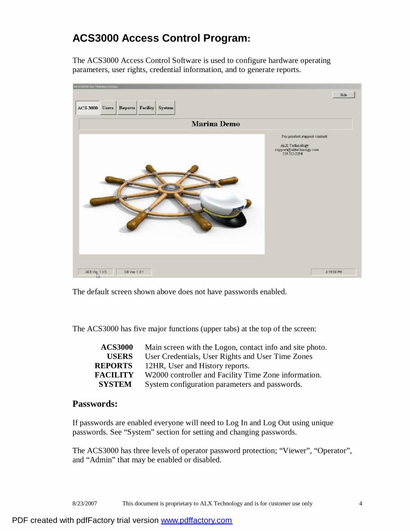
ACS3000 Access Control Program: The ACS3000 Access Control Software is used to configure hardware operating parameters, user rights, credential information, and to generate reports.
The default screen shown above does not have passwords enabled. The ACS3000 has five major functions (upper tabs) at the top of the screen: ACS3000 Main screen with the Logon, contact info and site photo.
USERS User Credentials, User Rights and User Time Zones REPORTS 12HR, User and History reports. FACILITY W2000 controller and Facility Time Zone information. SYSTEM System configuration parameters and passwords.
Passwords: If passwords are enabled everyone will need to Log In and Log Out using unique passwords. See “System” section for setting and changing passwords. The ACS3000 has three levels of operator password protection; “Viewer”, “Operator”, and “Admin” that may be enabled or disabled.
PDF created with pdfFactory trial version www.pdffactory.com

8/23/2007 This document is proprietary to ALX Technology and is for customer use only 5
With passwords enabled the default login screen is shown below and allows no access to the ACS3000 system.
When logged in as “Viewer” access is granted to the ACS3000, Users, and Reports tabs as shown below. User info can be viewed but not modified.
When logged in as “Operator” the ACS3000, Users, Reports and Facility tab are available as shown below. The Reader Tables can be viewed but not modified.
PDF created with pdfFactory trial version www.pdffactory.com

8/23/2007 This document is proprietary to ALX Technology and is for customer use only 6
The following screen shows an “Admin” logged in and all tabs and functions are available.
Note: Only operators with Admin level rights will be allowed to close the ACS3000 program.
PDF created with pdfFactory trial version www.pdffactory.com

8/23/2007 This document is proprietary to ALX Technology and is for customer use only 7
USERS (upper tab):
Users are customers, employees, vendors and others who are issued credentials for use at the facility. Refer to “Getting Started”. The USER screen has three lower function tabs; Credential Assignments, User Access Rights and User Time Zones.
Users/Credential Assignments (lower tab) Credentials refer to the various types of key-cards, key-tags or keypad numbers that are presented to the various types of card readers to request access. This screen has a window on the right that displays a list of users and assigned credentials listed in alphabetical order. The sorting can be changed by clicking on the column headers “A/D”, “User Name”, “Credential #”, “UAR” or “Type”.
Use the up/down and right/left arrows to move though the list of users. Once a user name or credential has been located, it can be edited by double-clicking on the highlighted line or clicking on the Edit button.
PDF created with pdfFactory trial version www.pdffactory.com

8/23/2007 This document is proprietary to ALX Technology and is for customer use only 8
Entering new Users/Credentials: There are two ways to enter new credentials and user information when operating in the ACS3000 Standalone mode, as follows: Add New: Enter a new credential and user information; clears screen.
Add Next: Automatically increments the credential number and saves the previous user information.
Edit: Used to edit contents on the Credential screen. Remove: Removes the User Data; not recoverable. Save: Used to save any changes made on the screen. Cancel: Cancels any entries/edits and exits.
Note: Credentials may be viewed, but no additions or editing will be allowed if an outside Marina Management Software (MMS) application is selected as the source of the credential information. ADD NEW (button): This screen is used to enter a new credential number, user information and to select the User Access Rights (UAR) to be assigned to this user. Use the Tab key or mouse pointer to move between selections. User Name: Enter the user name that this credential is being assigned to. (Last name, First name) Active/D: A check mark indicates the credential is active; blank is de-active. Credential Number: Enter the credential or key-pad number (1 – 65535). User Type: Select, edit or enter a new name for user types; used for sorting in reports. Credential Type: If multiple credential types are in use, select the appropriate one
for the credential number being entered. UAR Name: Select the User Access Rights name from the drop down list. Contact Information: Enter pertinent address and phone number information. Comments: Space for additional information and comments such as slip # or
Tie-down, insurance, etc. ADD NEXT (button): This screen works the same as “Add New” except that it saves the previously typed User data and automatically increments the credential number by 1. This is a time saving method to use when entering a series of new credentials in numerical order. EDIT (button):
PDF created with pdfFactory trial version www.pdffactory.com
8/23/2007 This document is proprietary to ALX Technology and is for customer use only 9
Select a credential or user from the list box and double click or click the “Edit” button to highlight the screen contents. Changes can only be made in the “Edit” mode. REMOVE (button): This is used to delete or remove a user from the system. This
action is permanent. Note: Enter spaces or blanks in the credential field to remove the
assigned credential, but retain the User information. SAVE (button): Use this button to save any changes made. (not necessary if ‘Add
Next’ is clicked) CANCEL (button): Exits without saving any data entered.
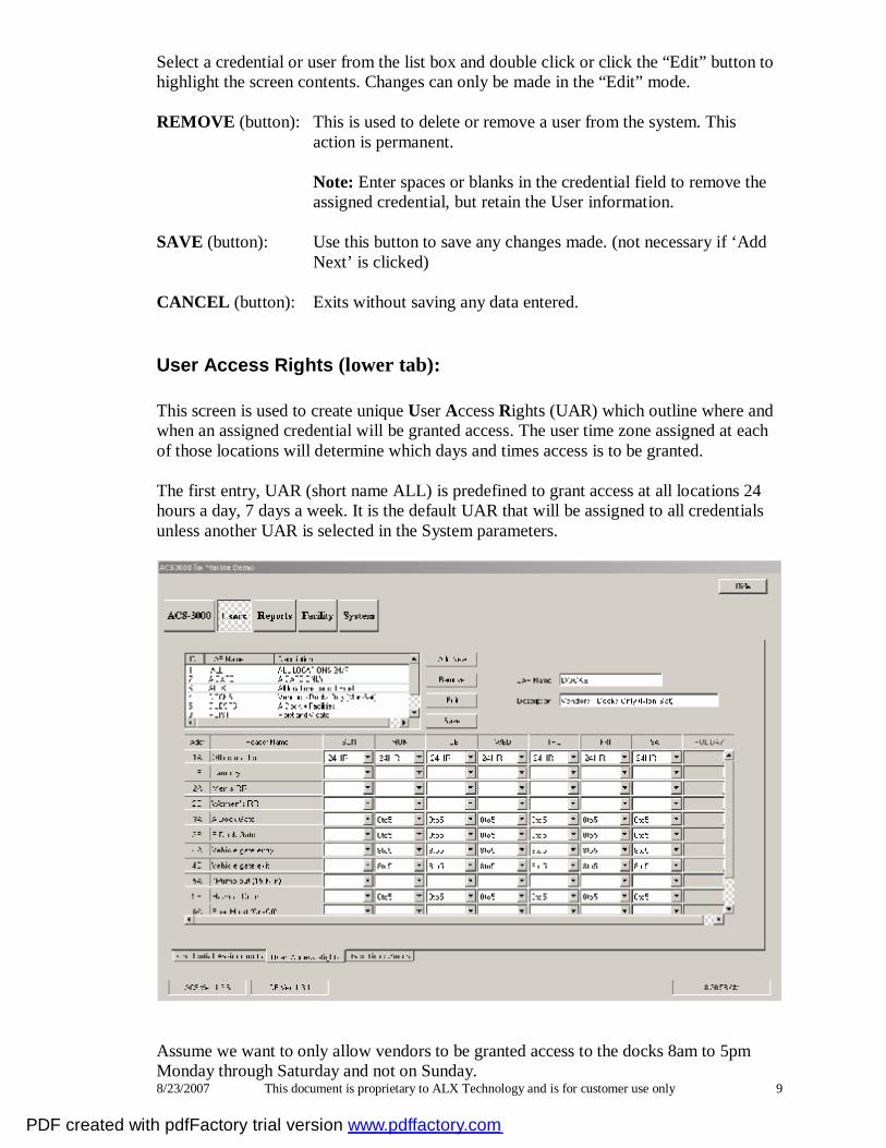
User Access Rights (lower tab): This screen is used to create unique User Access Rights (UAR) which outline where and when an assigned credential will be granted access. The user time zone assigned at each of those locations will determine which days and times access is to be granted. The first entry, UAR (short name ALL) is predefined to grant access at all locations 24 hours a day, 7 days a week. It is the default UAR that will be assigned to all credentials unless another UAR is selected in the System parameters.
Assume we want to only allow vendors to be granted access to the docks 8am to 5pm Monday through Saturday and not on Sunday.
PDF created with pdfFactory trial version www.pdffactory.com
8/23/2007 This document is proprietary to ALX Technology and is for customer use only 10
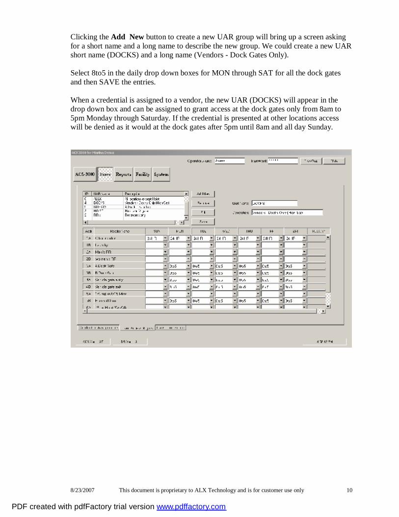
Clicking the Add New button to create a new UAR group will bring up a screen asking for a short name and a long name to describe the new group. We could create a new UAR short name (DOCKS) and a long name (Vendors - Dock Gates Only). Select 8to5 in the daily drop down boxes for MON through SAT for all the dock gates and then SAVE the entries. When a credential is assigned to a vendor, the new UAR (DOCKS) will appear in the drop down box and can be assigned to grant access at the dock gates only from 8am to 5pm Monday through Saturday. If the credential is presented at other locations access will be denied as it would at the dock gates after 5pm until 8am and all day Sunday.
PDF created with pdfFactory trial version www.pdffactory.com
8/23/2007 This document is proprietary to ALX Technology and is for customer use only 11
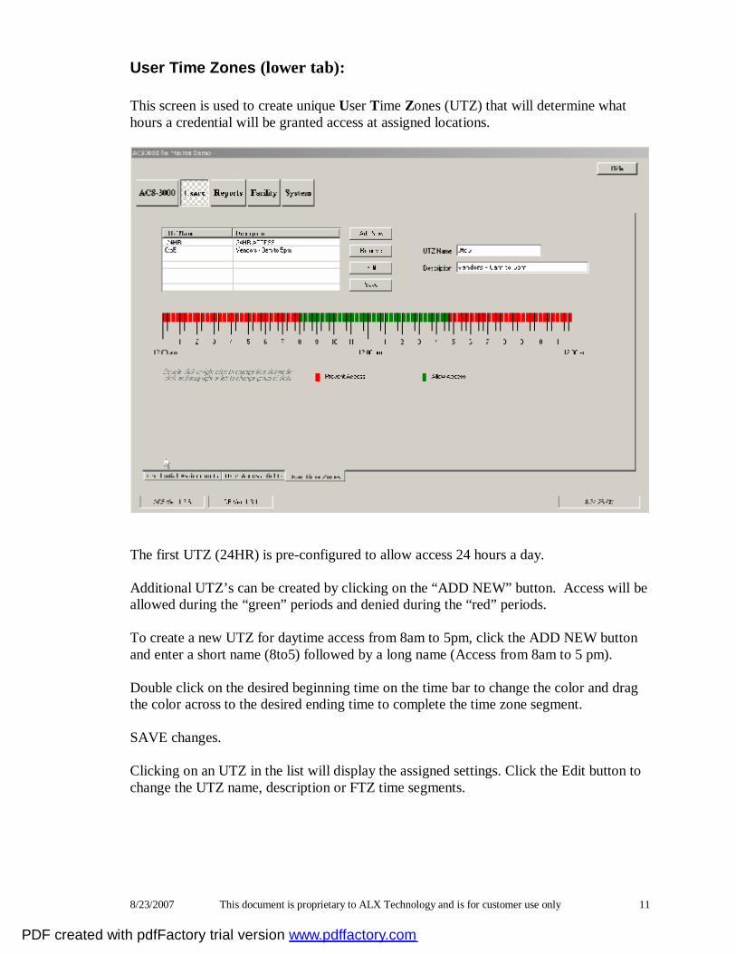
User Time Zones (lower tab): This screen is used to create unique User Time Zones (UTZ) that will determine what hours a credential will be granted access at assigned locations.
The first UTZ (24HR) is pre-configured to allow access 24 hours a day. Additional UTZ’s can be created by clicking on the “ADD NEW” button. Access will be allowed during the “green” periods and denied during the “red” periods. To create a new UTZ for daytime access from 8am to 5pm, click the ADD NEW button and enter a short name (8to5) followed by a long name (Access from 8am to 5 pm). Double click on the desired beginning time on the time bar to change the color and drag the color across to the desired ending time to complete the time zone segment. SAVE changes. Clicking on an UTZ in the list will display the assigned settings. Click the Edit button to change the UTZ name, description or FTZ time segments.
PDF created with pdfFactory trial version www.pdffactory.com
8/23/2007 This document is proprietary to ALX Technology and is for customer use only 12
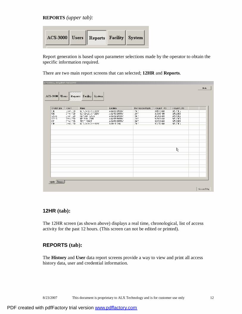
REPORTS (upper tab):
Report generation is based upon parameter selections made by the operator to obtain the specific information required. There are two main report screens that can selected; 12HR and Reports.
12HR (tab): The 12HR screen (as shown above) displays a real time, chronological, list of access activity for the past 12 hours. (This screen can not be edited or printed).
REPORTS (tab): The History and User data report screens provide a way to view and print all access history data, user and credential information.
PDF created with pdfFactory trial version www.pdffactory.com
8/23/2007 This document is proprietary to ALX Technology and is for customer use only 13
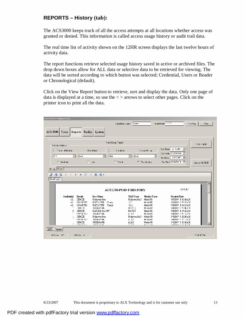
REPORTS – History (tab): The ACS3000 keeps track of all the access attempts at all locations whether access was granted or denied. This information is called access usage history or audit trail data. The real time list of activity shown on the 12HR screen displays the last twelve hours of activity data. The report functions retrieve selected usage history saved in active or archived files. The drop down boxes allow for ALL data or selective data to be retrieved for viewing. The data will be sorted according to which button was selected; Credential, Users or Reader or Chronological (default). Click on the View Report button to retrieve, sort and display the data. Only one page of data is displayed at a time, so use the < > arrows to select other pages. Click on the printer icon to print all the data.
PDF created with pdfFactory trial version www.pdffactory.com

8/23/2007 This document is proprietary to ALX Technology and is for customer use only 14
REPORTS - Users (tab): Use the drop down boxes shown to select the sorting order for the various User data fields in ascending or descending order. The example below shows User data sorted by credential in ascending credential order.
PDF created with pdfFactory trial version www.pdffactory.com
8/23/2007 This document is proprietary to ALX Technology and is for customer use only 15
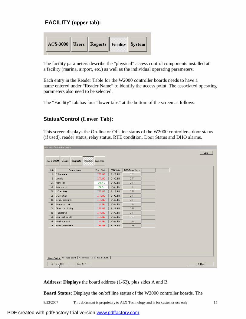
FACILITY (upper tab):
The facility parameters describe the “physical” access control components installed at a facility (marina, airport, etc.) as well as the individual operating parameters. Each entry in the Reader Table for the W2000 controller boards needs to have a name entered under “Reader Name” to identify the access point. The associated operating parameters also need to be selected. The “Facility” tab has four “lower tabs” at the bottom of the screen as follows:
Status/Control (Lower Tab): This screen displays the On-line or Off-line status of the W2000 controllers, door status (if used), reader status, relay status, RTE condition, Door Status and DHO alarms.
Address: Displays the board address (1-63), plus sides A and B. Board Status: Displays the on/off line status of the W2000 controller boards. The
PDF created with pdfFactory trial version www.pdffactory.com
8/23/2007 This document is proprietary to ALX Technology and is for customer use only 16
normal condition should be “on-line” indicating that the controllers are sending all access requests to the ACS3000 control program on the PC which determines whether the request will be granted or denied. If the status is “off-line” it means that there is a communication problem with the controller that needs to be resolved.
RDR Status: Displays the current status of the reader on each W2000. (Enabled or Disabled) RLY Status: Displays the current status of the relays on each W2000 (ON – door unlocked or OFF – door locked) RTE: Request to Exit is an input on the W2000 controller that allows a relay to
be activated manually in place of using a credential. This function is normally used to release magnetic locks to exit a controlled location. Clicking this button on the screen will initiate a timed release from the PC if it is configured in the Reader Tables.
Door Status: Displays the door open or closed condition if door position sensors are
installed and wired to the associated W2000 controller board. DHO Alarm: Relay 2 is used to activate an audible alarm and/or strobe light under
certain conditions such as the Door being Held Open (DHO) beyond the allowed “open time” as configured in the Reader Tables.
Note: The DHO alarm turns off when the door/gate is closed again.
PDF created with pdfFactory trial version www.pdffactory.com
8/23/2007 This document is proprietary to ALX Technology and is for customer use only 17
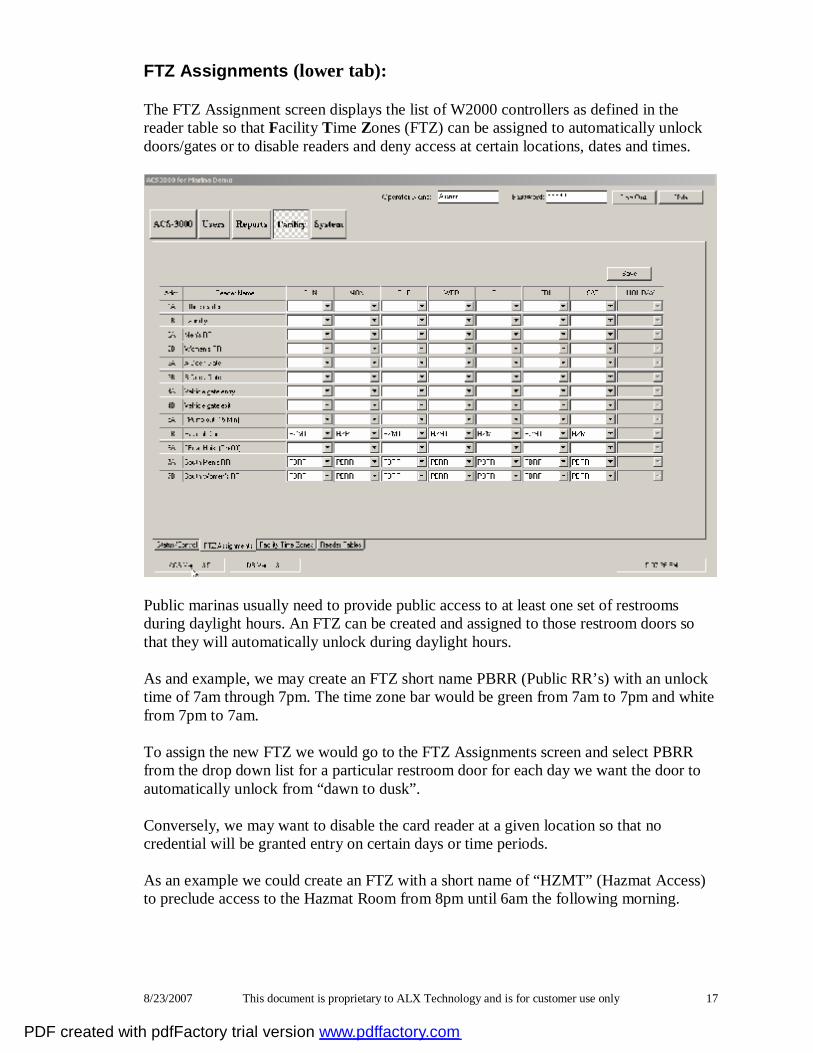
FTZ Assignments (lower tab): The FTZ Assignment screen displays the list of W2000 controllers as defined in the reader table so that Facility Time Zones (FTZ) can be assigned to automatically unlock doors/gates or to disable readers and deny access at certain locations, dates and times.
Public marinas usually need to provide public access to at least one set of restrooms during daylight hours. An FTZ can be created and assigned to those restroom doors so that they will automatically unlock during daylight hours. As and example, we may create an FTZ short name PBRR (Public RR’s) with an unlock time of 7am through 7pm. The time zone bar would be green from 7am to 7pm and white from 7pm to 7am. To assign the new FTZ we would go to the FTZ Assignments screen and select PBRR from the drop down list for a particular restroom door for each day we want the door to automatically unlock from “dawn to dusk”. Conversely, we may want to disable the card reader at a given location so that no credential will be granted entry on certain days or time periods. As an example we could create an FTZ with a short name of “HZMT” (Hazmat Access) to preclude access to the Hazmat Room from 8pm until 6am the following morning.
PDF created with pdfFactory trial version www.pdffactory.com
8/23/2007 This document is proprietary to ALX Technology and is for customer use only 18
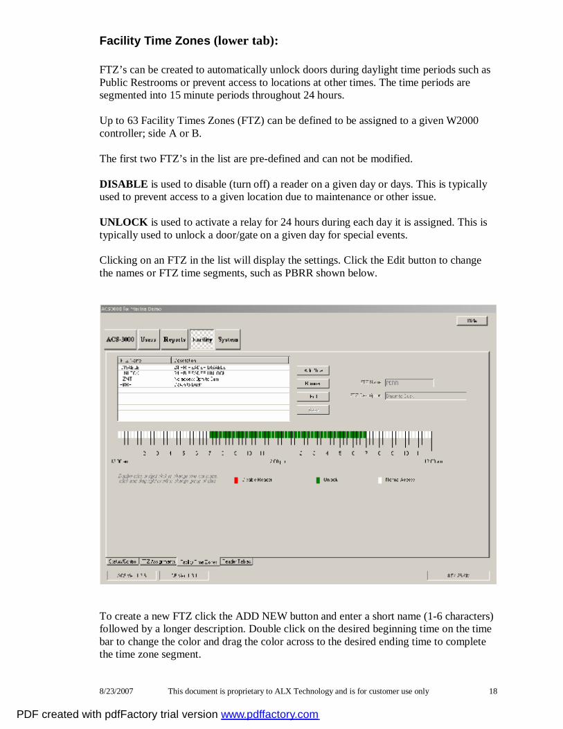
Facility Time Zones (lower tab): FTZ’s can be created to automatically unlock doors during daylight time periods such as Public Restrooms or prevent access to locations at other times. The time periods are segmented into 15 minute periods throughout 24 hours. Up to 63 Facility Times Zones (FTZ) can be defined to be assigned to a given W2000 controller; side A or B. The first two FTZ’s in the list are pre-defined and can not be modified. DISABLE is used to disable (turn off) a reader on a given day or days. This is typically used to prevent access to a given location due to maintenance or other issue. UNLOCK is used to activate a relay for 24 hours during each day it is assigned. This is typically used to unlock a door/gate on a given day for special events. Clicking on an FTZ in the list will display the settings. Click the Edit button to change the names or FTZ time segments, such as PBRR shown below.
To create a new FTZ click the ADD NEW button and enter a short name (1-6 characters) followed by a longer description. Double click on the desired beginning time on the time bar to change the color and drag the color across to the desired ending time to complete the time zone segment.
PDF created with pdfFactory trial version www.pdffactory.com

8/23/2007 This document is proprietary to ALX Technology and is for customer use only 19
To assign it we would go to FTZ Assignments and select HZMT from the drop down list for each day we want to automatically disable the Hazmat door from 8pm to 6am. Note: More detailed information is available in the Configuration and Setup sections. The example of an FTZ with a short name of “HZMT” (Hazmat Access) to preclude access to the Hazmat Room from 8pm until 6am the following morning is shown on the screen below.
The facility time zone bar would be white from 6am to 8pm and red from 8pm to 6am. Note: The SAVE button needs to be selected before the data changes will take effect.
PDF created with pdfFactory trial version www.pdffactory.com
8/23/2007 This document is proprietary to ALX Technology and is for customer use only 20
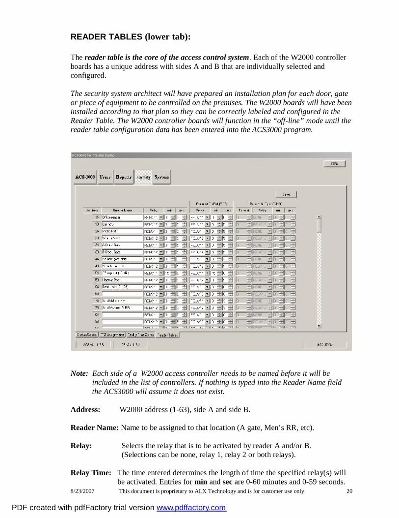
READER TABLES (lower tab): The reader table is the core of the access control system. Each of the W2000 controller boards has a unique address with sides A and B that are individually selected and configured. The security system architect will have prepared an installation plan for each door, gate or piece of equipment to be controlled on the premises. The W2000 boards will have been installed according to that plan so they can be correctly labeled and configured in the Reader Table. The W2000 controller boards will function in the “off-line” mode until the reader table configuration data has been entered into the ACS3000 program.
Note: Each side of a W2000 access controller needs to be named before it will be included in the list of controllers. If nothing is typed into the Reader Name field the ACS3000 will assume it does not exist. Address: W2000 address (1-63), side A and side B. Reader Name: Name to be assigned to that location (A gate, Men’s RR, etc). Relay: Selects the relay that is to be activated by reader A and/or B. (Selections can be none, relay 1, relay 2 or both relays). Relay Time: The time entered determines the length of time the specified relay(s) will
be activated. Entries for min and sec are 0-60 minutes and 0-59 seconds.
PDF created with pdfFactory trial version www.pdffactory.com
8/23/2007 This document is proprietary to ALX Technology and is for customer use only 21
Note: Typical entries are 3 sec for doors and 5 sec for dock gates. A 0 entry will cause a “toggle” effect such that a valid key-card will activate the relay(s) and the same or another valid key-card will be needed to deactivate the relay(s).
Note: The “toggle” function is used to control equipment such as fish cranes, pressure washers and pump outs.
RTE Relay: The W2000 controllers have a sensor input called Request-To-Exit (RTE)
that is used to activate a relay to unlock a door or gate. In some instances a button or sensor is placed on the ramp side of a dock gate that can be used to unlock the gate to exit the dock. This is typically used for gates with magnetic locks and the release button is placed far enough away from the gate so someone can’t reach in to push the button.
Note: The RTE time is usually set to a value longer than the normal relay
activation time so the gate stays unlocked long enough to walk up to, and through, before it relocks.
DHO Relay: The W2000 controllers have another sensor input called Door Held Open
(DHO) that is used to monitor the time a door or gate is held open. If the DHO time is set to 5 minutes and the gate is held open for 5 minutes or longer, relay 2 will be activated for the amount of time specified. Relay 2 is usually connected to an audible alarm and/or strobe light.
Note: Closing the doot/gate will reset the door status and DHO alarm.
PDF created with pdfFactory trial version www.pdffactory.com

8/23/2007 This document is proprietary to ALX Technology and is for customer use only 22
SYSTEM (upper tab):
Various System parameters need to be configured prior to system operation. These screens can only be modified with “administrator” rights if passwords are enabled.
Left side Screen functions: Facility Name: Enter the name of the facility which will be displayed on the main
ACS3000 screen upon startup. Credential Format: Select the type of 26 bit Wiegand credentials to be used. W26-STD – Standard 26 bit Wiegand formatted credentials. W26-ALX – ALX 26 bit Wiegand formatted credentials Facility Codes: Most facilities will have a single credential facility code, but up to
five can be selected as needed. The default is usually the 1st entry, the FC # (0-255), “Credentials” and the Display box not checked.
Passwords: When enabled, the three levels of passwords are:
PDF created with pdfFactory trial version www.pdffactory.com
8/23/2007 This document is proprietary to ALX Technology and is for customer use only 23
Admin - allows the administrator to view and modify all
ACS3000 functions. (default password is Admin) Operator - allows the user to view and modify credential data and run reports. (default password is Operator) Viewer - allows the user to view, but not modify credential data or run reports. (default password is Viewer) Right side Screen functions: Close ACS3000: This is the only was to close (turn off) the ACS3000 program and
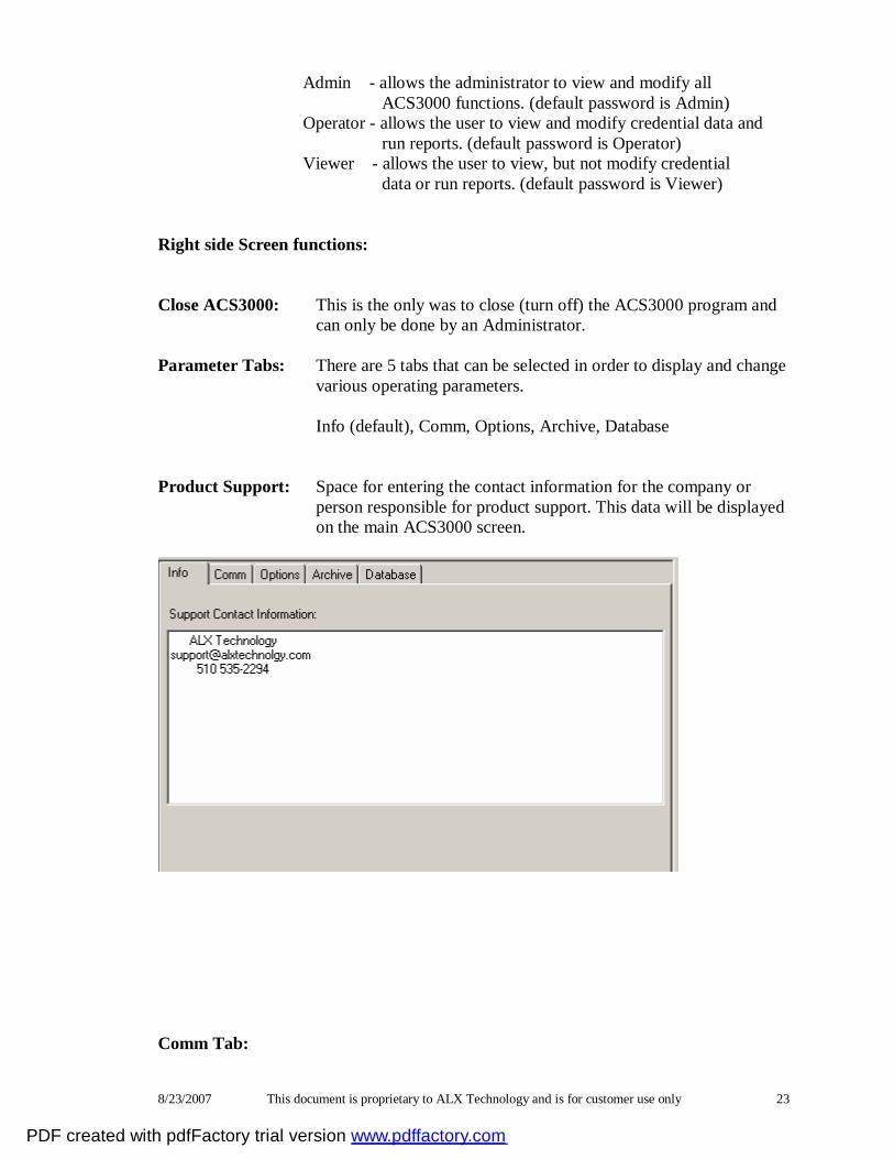
can only be done by an Administrator. Parameter Tabs: There are 5 tabs that can be selected in order to display and change various operating parameters. Info (default), Comm, Options, Archive, Database Product Support: Space for entering the contact information for the company or
person responsible for product support. This data will be displayed on the main ACS3000 screen.
Comm Tab:
PDF created with pdfFactory trial version www.pdffactory.com

8/23/2007 This document is proprietary to ALX Technology and is for customer use only 24
Comm Port#: Select the serial communications port for the AIP2000 to use to
communicate with the W2000 boards. (Com1) Comm Delay: This delay is used with radios installed so that the PC responses to
W2000 controller requests do not overrun the radio latency. Loop Delay: This value determines how often the W2000 controllers listed in
the Reader tables are polled. In small systems this parameter is usually set to 1 minute and to 5 minutes in large systems.
Enable Logging: Turning this function on will cause all transactions to be logged
into the \ACS3000\ACS_Logs folder. Used for diagnostics only. Disconnect: Clicking this button will disable communications with the W2000
controllers. When disconnected the name will change to Connect. Clicking the button again will re-enable communications. This
function is used during software updates and diagnostics.
PDF created with pdfFactory trial version www.pdffactory.com
8/23/2007 This document is proprietary to ALX Technology and is for customer use only 25
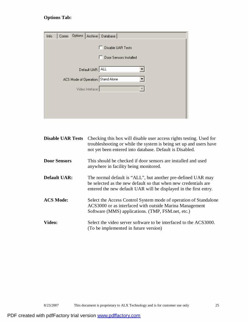
Options Tab:
Disable UAR Tests Checking this box will disable user access rights testing. Used for
troubleshooting or while the system is being set up and users have not yet been entered into database. Default is Disabled.
Door Sensors This should be checked if door sensors are installed and used
anywhere in facility being monitored. Default UAR: The normal default is “ALL”, but another pre-defined UAR may
be selected as the new default so that when new credentials are entered the new default UAR will be displayed in the first entry.
ACS Mode: Select the Access Control System mode of operation of Standalone
ACS3000 or as interfaced with outside Marina Management Software (MMS) applications. (TMP, FSM.net, etc.)
Video: Select the video server software to be interfaced to the ACS3000.
(To be implemented in future version)
PDF created with pdfFactory trial version www.pdffactory.com
8/23/2007 This document is proprietary to ALX Technology and is for customer use only 26
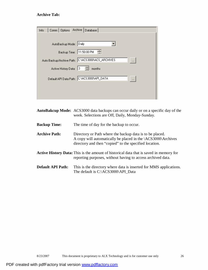
Archive Tab:
AutoBakcup Mode: ACS3000 data backups can occur daily or on a specific day of the week. Selections are Off, Daily, Monday-Sunday. Backup Time: The time of day for the backup to occur. Archive Path: Directory or Path where the backup data is to be placed.
A copy will automatically be placed in the \ACS3000\Archives directory and then “copied” to the specified location.
Active History Data: This is the amount of historical data that is saved in memory for reporting purposes, without having to access archived data. Default API Path: This is the directory where data is inserted for MMS applications. The default is C:\ACS3000\API_Data
PDF created with pdfFactory trial version www.pdffactory.com
8/23/2007 This document is proprietary to ALX Technology and is for customer use only 27
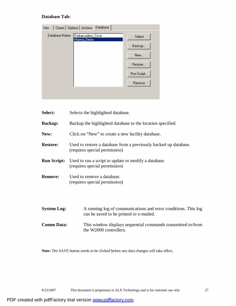
Database Tab:
Select: Selects the highlighted database. Backup: Backup the highlighted database to the location specified. New: Click on “New” to create a new facility database. Restore: Used to restore a database from a previously backed up database. (requires special permission) Run Script: Used to run a script to update or modify a database. (requires special permission) Remove: Used to remove a database. (requires special permission)
System Log: A running log of communications and error conditions. This log can be saved to be printed or e-mailed.
Comm Data: This window displays sequential commands transmitted to/from
the W2000 controllers.
Note: The SAVE button needs to be clicked before any data changes will take effect.
PDF created with pdfFactory trial version www.pdffactory.com
8/23/2007 This document is proprietary to ALX Technology and is for customer use only 28
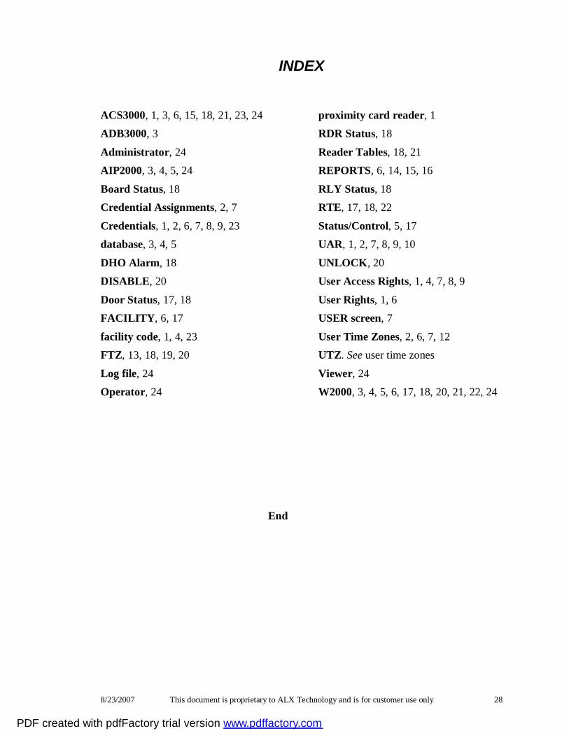
INDEX
ACS3000, 1, 3, 6, 15, 18, 21, 23, 24 ADB3000, 3
Administrator, 24 AIP2000, 3, 4, 5, 24
Board Status, 18 Credential Assignments, 2, 7
Credentials, 1, 2, 6, 7, 8, 9, 23 database, 3, 4, 5
DHO Alarm, 18 DISABLE, 20
Door Status, 17, 18 FACILITY, 6, 17
facility code, 1, 4, 23 FTZ, 13, 18, 19, 20
Log file, 24 Operator, 24
proximity card reader, 1 RDR Status, 18
Reader Tables, 18, 21 REPORTS, 6, 14, 15, 16
RLY Status, 18 RTE, 17, 18, 22
Status/Control, 5, 17 UAR, 1, 2, 7, 8, 9, 10
UNLOCK, 20 User Access Rights, 1, 4, 7, 8, 9
User Rights, 1, 6 USER screen, 7
User Time Zones, 2, 6, 7, 12 UTZ. See user time zones
Viewer, 24 W2000, 3, 4, 5, 6, 17, 18, 20, 21, 22, 24
End
PDF created with pdfFactory trial version www.pdffactory.com