Embed Size (px)
Citation preview
Filter/regulator standard white Series
W1000/W2000/W3000/W4000/W8000-W SeriesNew Series of 5µm elements for dust removal, and 0.3µm elements for tar removal. Port size: 1/8 to 1
Ozone specifications (Ending 11)
● Dust generation preventing structure for use in cleanrooms
Clean room specifications (catalog No. CB-033S)
P11W*000 - · · · · · · - W - · · · · · · -
P7*W*000 - · · · · · · · · · · · · · · · · · -
Specifications
Note 1: When "F1" with an automatic drain is selected for the W1000-W series, minimum operating pressure is 0.2 MPa, maximum operation pressure is 0.7 MPa and withstanding pressure is 1.05 MPa. Refer to the maximum processing flow table (page 350) for the F1000-W-F1 automatic drain for the maximum working flow. Set the working flow to less than the maximum working flow.
Note 2: When "F" with an automatic drain is selected, minimum operation pressure must be 0.1 MPa. Air is purged with initial drainage until pressure reaches 0.1 MPa.
Note 3: When "F1" with an automatic drain is selected, minimum operation pressure must be 0.15 MPa. Note 4: The working temperature range of the pressure switch with indicator PPD assembly "R1" is 5 to 50°C. Note 5: Drainage accumulates up to 170 cm3 only with the manual drain cock. Note 6: When using the "F1" with automatic drain, use the W2000-W Series at less than the maximum flow rate. (Refer to F2000-W on page 350 for the maximum flow rate.)
Descriptions W1000-W W2000-W W3000-W W4000-W W8000-W
Appearance
Working fluid Compressed airMax. working pressure MPa 1.0 Notes 1, 2, 3Withstanding pressure MPa 1.5 Note 1Ambient temperature range °C 5 to 60Filtration rating µm 5 5 or 0.3Set pressure range MPa 0.05 to 0.85 Note 1 0.05 to 0.85Relief With relief mechanismDrain capacity cm3 12 25 45 80 80 (Note 5)Port size Rc, NPT, G 1/8, 1/4 (3/8 uses an adaptor) 1/4, 3/8 (1/2 uses an adaptor) 1/4, 3/8 (1/2 uses an adaptor) 1/4, 3/8, 1/2 (3/4 uses an adaptor) 3/4, 1 (1 1/4 uses an adaptor)Product weight kg 0.175 0.40 0.6 0.9 2.0Standard accessories Pressure gauge and bowl guard
Note 4
● Structured for use in secondary battery manufacturing processes
Secondary battery compatible specifications (catalog No. CC-947)
P4*W*000 - · · · · · · · · · · · · · · · · · -
JIS symbol
334
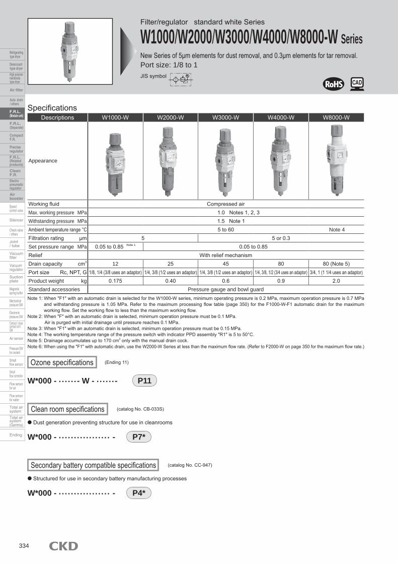
Filter/Regulator SeriesHow to order
Model no.A
Attachment (attached)
G
Display unitE
Piping adaptor set (attached)
F
OptionD
Port thread typeC
Port sizeB
W1000 66 W Z A6W
Model no.W1000
W2000
W3000
W4000
W8000
Symbol DescriptionsPort size
6 1/8 ●
8 1/4 ● ● ● ●
10 3/8 ● ● ●
15 1/2 ●
20 3/4 ●
25 1 ●
Port thread type Note 1Blank Rc thread ● ● ● ● ●
N NPT thread ● ● ● ● ●
G G thread ● ● ● ● ●
Option Note 2
Drainage
Note 3
Blank With manual drain cock ● ● ● ● ●
F Auto. drain with manual override (NO type: Exhaust w/o pressurized) ● ● ●
F1 Auto. drain with manual override (NC type: No exhaust w/o pressurized) ● ● ● ● ●
FF Large auto. drain with manual override (NO type: Exhaust w/o pressurized) ●
FF1 Large auto. drain with manual override (NC type: No exhaust w/o pressurized) ●
Bowl material
Blank Polycarbonate bowl ● ● ● ● ●
Z Nylon bowl ● ● ● ● ●
M Metal bowl ● ● ●
M1 Metal bowl with manual drain cock ● ● ● ●
ElementBlank 5μm ● ● ● ● ●
Y 0.3µm (submicron) Note 4 ● ● ●
PressureRange
Blank 0.05 to 0.85MPa ● ● ● ● ●
L 0.05 to 0.35MPa Note 5 ● ● ● ● ●
ReliefBlank With relief mechanism ● ● ● ● ●
N Nonrelief type ● ● ● ● ●
Pressure gauge
Blank With standard pressure gauge (G401-W) ● ● ● ● ●
T W/o pressure gauge (pressure gauge port (Rc1/4) is assembled with sealed) ● ● ● ● ●
T8 Pressure gauge attached (pressure gauge port (Rc1/4) is assembled by open) ● ● ● ● ●
T6 Digital pressure sensor PPX attachment option Note 6 ● ● ● ● ●
R1 Pressure switch with display PPD assembly Note 7 ● ● ● ●
FlowDirection
Blank Standard flow (left → right) ● ● ● ● ●
X1 Reverse flow (right → left) ● ● ● ● ●
Display unitBlank MPa display, Rc thread ● ● ● ● ●
J1 MPa display, NPT, G thread ● ● ● ● ●
Piping adaptor set (attached) Note 8, Note 9 Page 428Blank Not attached ● ● ● ● ●
A6*W Rc1/8 piping adaptor set ●
A8*W Rc1/4 piping adaptor set ● ● ● ●
A10*W Rc3/8 piping adaptor set ● ● ● ●
A15*W Rc1/2 piping adaptor set ● ● ●
A20*W Rc3/4 piping adaptor set ● ●
A25*W Rc1 piping adaptor set ●
A32*W Rc1 1/4 piping adaptor set ●
*Adaptor screw typeBlank Rc thread ● ● ● ● ●
N NPT thread ● ● ● ● ●
G G thread ● ● ● ● ●
Attachment (attached) Note 10 Page 425, page 659Blank Not attached ● ● ● ● ●
BW C type bracket ● ● ● ● ●
B3W L type bracket Note 11 ● ● ● ●
G45P G45D-8-P10(L:G45D-8-P04) ● ● ● ● ●
G49P G49D-8-P10(L:G49D-8-P04) ● ● ● ● ●
G59P G59D-8-P10(L:G59D-8-P04) ● ● ● ●
G40P G40D-8-P10(L:G40D-8-P04) ● ● ● ● ●
G50P G50D-8-P10(L:G50D-8-P04) ● ● ● ●
G41P G41D-8-P10(L:G41D-8-P04) ● ● ● ● ●
G52P G52D-8-P10(L:G52D-8-P10) ● ● ● ● ●
R2 Note 6 Digital pressure sensor: PPX-R10N-6M ● ● ● ● ●
A
B
G
F
E
D
C
* Refer to page 274 for the explanation of the option.
Note on model no. selectionNote 1: When G threads or NPT threads are selected, the IN, OUT,
gauge port, and drainage discharge port (metal bowl automatic drain) are the target.
Note 2: Select options per drainage, bowl material, element, and regulator sections.
When selecting options for several items, list options in order from the top.
Note 3: Refer to page 276 for the automatic drain use conditions. Note 4: Refer to page 352 for maximum processing flow when option "Y"
is selected. Note 5: The pressure gauge's indication range is 0 to 0.4MPa for option "L".Note 6: When "D" option "T6" is selected, only "Blank" or "R2" can be
selected for pressure gauge (enclosed). The digital pressure sensor PPX mounting port (Rc1/8) is assembled by open.
Note 7: The output type is NPN transistor output. Consult with CKD when the PNP transistor output is required.
Note 8: The C-type bracket and piping adaptor set attachments cannot be used at the same time.
Note 9: The joiner set is enclosed with the piping adaptor set. Note 10: If NPT is selected for the "C" piping thread, a NPT pressure
gauge is enclosed. If Rc or G thread is selected, an R thread pressure gauge is enclosed.
Note 11: Refer to Section 2. Regulator , in " PRECAUTIONS for Installation and Adjustment " (page 279) for details on mounting the L-type bracket.
335
How to order

Flow characteristic● W1000-6-W ● W1000-8-W ● W2000-8-W
● W3000-10-W
● W4000-15-W● W4000-8-W ● W4000-10-W
Filter/Regulator Series
Pressure characteristic● W1000-W ● W2000-W ● W3000-W
● W8000-W● W4000-W
● W8000-20-W ● W8000-25-W
● W2000-10-W ● W3000-8-W
336
Seco
ndary
pres
sure
(MPa
)Se
cond
ary pr
essu
re (M
Pa)
Seco
ndary
pres
sure
(MPa
)Se
cond
ary pr
essu
re (M
Pa)
Seco
ndary
pres
sure
(MPa
)Se
cond
ary pr
essu
re (M
Pa)
Seco
ndary
pres
sure
(MPa
)Se
cond
ary pr
essu
re (M
Pa)
Seco
ndary
pres
sure
(MPa
)Se
cond
ary pr
essu
re (M
Pa)
Seco
ndary
pres
sure
(MPa
)Se
cond
ary pr
essu
re (M
Pa)
Seco
ndary
pres
sure
(MPa
)Se
cond
ary pr
essu
re (M
Pa)
Seco
ndary
pres
sure
(MPa
)Se
cond
ary pr
essu
re (M
Pa)
0.6
0.5
0.4
0.3
0.2
0.1
00.5 1.0 1.5
Air flow rate (m3/min. (ANR))
Primary pressure 0.7 MPa0.6
0.5
0.4
0.3
0.2
0.1
00.5 1.0 1.5
Air flow rate (m3/min. (ANR))
Primary pressure 0.7 MPa
Air flow rate (m3/min. (ANR))
Primary pressure 0.7 MPa
Air flow rate (m3/min. (ANR))
Primary pressure 0.7 MPa
0.6
0.5
0.4
0.3
0.2
0.1
01.0 2.0 5.0
Air flow rate (m3/min. (ANR))
Primary pressure 0.7 MPa
0.6
0.5
0.4
0.3
0.2
0.1
01.0 3.0 5.0
Air flow rate (m3/min. (ANR))
Primary pressure 0.7 MPa
2.0 4.0
3.0 4.0
0.6
0.5
0.4
0.3
0.2
0.1
00.5 1.5 2.51.0 2.0
0.6
0.5
0.4
0.3
0.2
0.1
01.0 3.0 5.02.0 4.0
0.24
0.22
0.2
0.18
0.16
0.2 0.6
Primary pressure (MPa)
Setting pressure
0.4 0.8
0.21
0.2
0.19
0.18
0.17
0.2 0.6
Primary pressure (MPa)
Setting pressure
0.4 0.80
0.21
0.2
0.19
0.18
0.17
0.2 0.6
Primary pressure (MPa)
Setting pressure
0.4 0.80
0.24
0.22
0.2
0.18
0.16
0.2 0.6
Primary pressure (MPa)
Setting pressure
0.4 0.80
Air flow rate (m3/min. (ANR))
Primary pressure 0.7 MPa
Air flow rate (m3/min. (ANR))
Primary pressure 0.7 MPa0.6
0.5
0.4
0.3
0.2
0.1
0 1 3 102 9
0.6
0.5
0.4
0.3
0.2
0.1
4 5 6 7 8 0 1 3 102 94 5 6 7 8
0.5
0.4
0.3
0.2
0.1
01.0 2.0 2.5
Air flow rate (m3/min. (ANR))
Primary pressure 0.7 MPa
1.50.5
0.60.6
0.5
0.4
0.3
0.2
0.1
0
0.7Primary pressure 0.7 MPa
0.5 1.5 2.51 2 3
Air flow rate (m3/min. (ANR))
0.6
0.5
0.4
0.3
0.2
0.1
0
0.7Primary pressure 0.7 MPa
0.5 1.5 2.51 2
Air flow rate (m3/min. (ANR))
0.24
0.22
0.2
0.18
0.16
0.2 0.60.4 0.80 1
Primary pressure (MPa)
Setting pressure
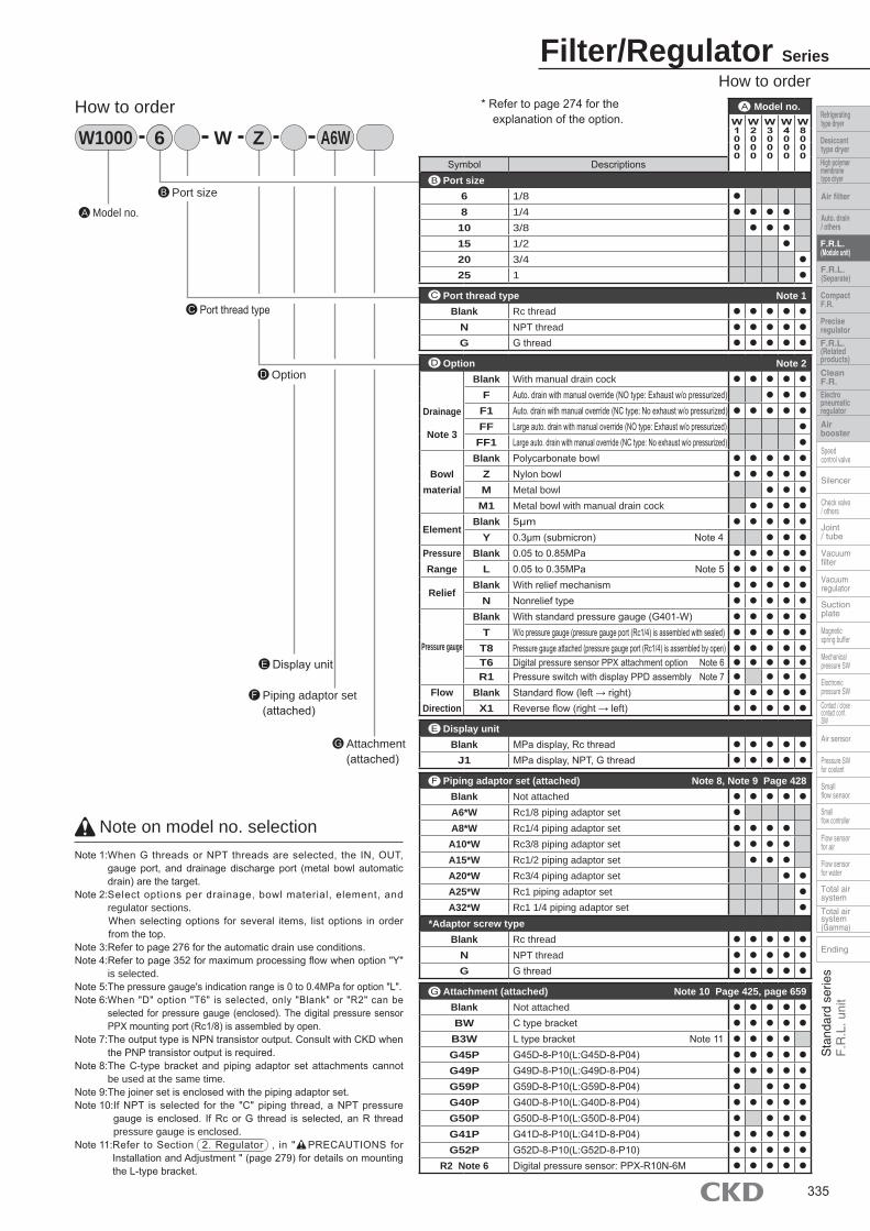
No. Parts nameMaterial
W1000-W W2000-W W3000-W W4000-W W8000-W1 Plate cover ABS resin - ABS resin
2 Body Polyamide resin, steel Aluminum alloy die-casting
3 O ring Special nitrile rubber
4 Element Polyacetal resin Polypropylene Polypropylene
5 Diaphragm assembly Polyacetal resin Polypropylene Polyacetal resin, nitrile rubber Zinc alloy die-casting, nitrile rubber
6 Cover Polyamide resin PBT resin Aluminum alloy die-casting
7 Knob Polyacetal resin
8 Valve assembly Brass, hydrogen nitrile rubber (polyacetal resin: W2000-W, W3000-W, W4000-W only)
9 Pressure gauge assembly PBT resin, polyacetal resin, polycarbonate resin, nitrile rubber, brass, steel
10Gage plug assembly - Polyamide resin, nitrile rubber, steel
Blanking plug assembly PBT resin, nitrile rubber, steel -
11 Bowl assembly Polycarbonate resin, polyacetal resin, urethane resin
12 Bowl guard Polyamide resin Polyamide resin
Note 1: W1000-W is element assembly. Note 2: O-ring of W1000-W is special shaped.
Note 2
Note 1
Internal structure and parts list● W1000-W ● W2000-W
● W3000-W/W4000-W
Filter/Regulator SeriesInternal structure and parts list
● W8000-W
337
IN OUT
4
2
6
7
3
11
12
8
5 1
9
4
2
6
7
3
11
12
8
5
1
9 10
IN OUT
IN OUT
4
2
6
7
3
11
12
8
5
1
9
10
IN OUT
7
6
5
2
3
4
11
12
8
9 10
Filter/Regulator Series
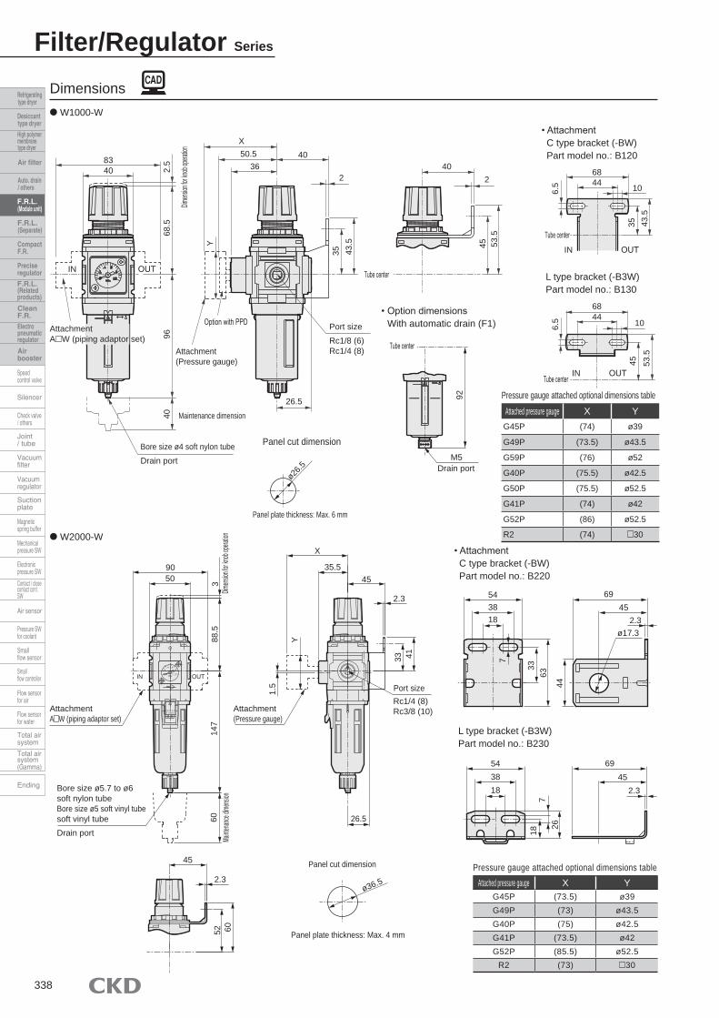
Dimensions● W1000-W
● W2000-W
Attached pressure gauge X YG45P (73.5) ø39G49P (73) ø43.5G40P (75) ø42.5G41P (73.5) ø42G52P (85.5) ø52.5
R2 (73) 30
Pressure gauge attached optional dimensions table
• AttachmentC type bracket (-BW)Part model no.: B220
L type bracket (-B3W)Part model no.: B230
Attached pressure gauge X YG45P (74) ø39
G49P (73.5) ø43.5
G59P (76) ø52
G40P (75.5) ø42.5
G50P (75.5) ø52.5
G41P (74) ø42
G52P (86) ø52.5
R2 (74) 30
Pressure gauge attached optional dimensions table
Panel cut dimension
• AttachmentC type bracket (-BW)Part model no.: B120
L type bracket (-B3W)Part model no.: B130
• Option dimensions With automatic drain (F1)
338
8340
IN OUT
2.5
68.5
9640
Dimens
ion for
knob
operati
on
AttachmentA W (piping adaptor set)
Option with PPD
Attachment (Pressure gauge)
Maintenance dimension
Bore size ø4 soft nylon tubeDrain port
Panel plate thickness: Max. 6 mm
Port sizeRc1/8 (6)Rc1/4 (8)
X50.5
3640
2
43.5
35
Y
26.5
Tube center
402
53.5
45
Tube center
92M5
Drain port
Tube center
Tube center
IN OUT
IN OUT
6844
68
10
10
45 53.5
43.5
35
6.5
6.5
ø26.5
44
X
35.545
2.3
88.5
543818
6945
2.3ø17.3
3363
44
543818
718
26
6945
2.3
AttachmentA W (piping adaptor set)
9050
IN OUT
3Dim
ension
for kn
ob ope
ration
147
60Ma
intenan
ce dim
ension
Attachment(Pressure gauge)
Port sizeRc1/4 (8)Rc3/8 (10)
26.5
1.5
Y
33 41
Bore size ø5.7 to ø6 soft nylon tubeBore size ø5 soft vinyl tubesoft vinyl tubeDrain port
45
2.3
52 60
Panel cut dimension
ø36.5
Panel plate thickness: Max. 4 mm
7
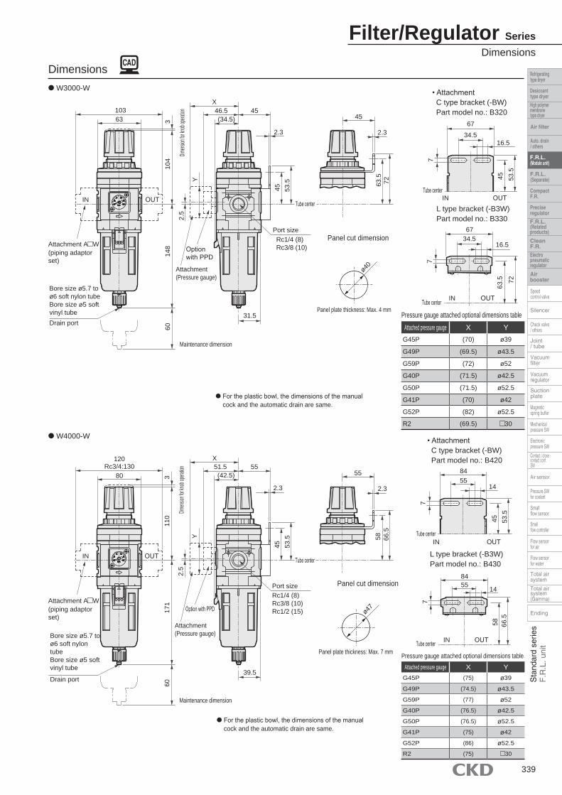
Filter/Regulator SeriesDimensions
Attached pressure gauge X YG45P (75) ø39
G49P (74.5) ø43.5
G59P (77) ø52
G40P (76.5) ø42.5
G50P (76.5) ø52.5
G41P (75) ø42
G52P (86) ø52.5
R2 (75) 30
Pressure gauge attached optional dimensions table
● W4000-W
● For the plastic bowl, the dimensions of the manual cock and the automatic drain are same.
Panel cut dimension
• AttachmentC type bracket (-BW)Part model no.: B420
L type bracket (-B3W)Part model no.: B430
● For the plastic bowl, the dimensions of the manual cock and the automatic drain are same.
Panel cut dimension
• AttachmentC type bracket (-BW) Part model no.: B320
L type bracket (-B3W) Part model no.: B330
Dimensions● W3000-W
Attached pressure gauge X YG45P (70) ø39
G49P (69.5) ø43.5
G59P (72) ø52
G40P (71.5) ø42.5
G50P (71.5) ø52.5
G41P (70) ø42
G52P (82) ø52.5
R2 (69.5) 30
Pressure gauge attached optional dimensions table
339
Bore size ø5.7 to ø6 soft nylon tubeBore size ø5 soft vinyl tube
Drain port
Attachment A W (piping adaptor set)
Option with PPD
Attachment (Pressure gauge)
Maintenance dimension
IN OUT
120Rc3/4:130
Dimens
ion for
knob
operati
on
80
171
110
3
2.5
Y
60
X51.5 55(42.5)
2.3
Port sizeRc1/4 (8)Rc3/8 (10)Rc1/2 (15)
53.5
45
Tube center
55
2.3
66.5
58
Panel plate thickness: Max. 7 mm
39.5
ø47
Tube center
Tube center
IN OUT
IN OUT
8455
84
14
14
58 66.5
53.5
45
77
55
45
Option with PPD
Attachment (Pressure gauge)
Maintenance dimension
Port sizeRc1/4 (8)Rc3/8 (10)
31.5
Bore size ø5.7 to ø6 soft nylon tubeBore size ø5 soft vinyl tubeDrain port
60
Attachment A W (piping adaptor set)
IN OUT
103
Dimens
ion for
knob
operati
on
63
148
104
3
2.5
Y
X46.5(34.5)
45
2.3
53.5
45 Tube centerIN OUT
Tube center
2.3
7263.5
67
53.5
45
16.534.5
7
Tube center IN OUT
67
63.5 72
16.534.5
7
Panel plate thickness: Max. 4 mm
ø40

Dimensions● W8000-W
Filter/Regulator Series
Attached pressure gauge X YG45P (85) ø39
G49P (84.5) ø43.5
G59P (87) ø52
G40P (86.5) ø42.5
G50P (86.5) ø52.5
G41P (85) ø42
G52P (98) ø52.5
R2 (85) 30
Pressure gauge attached optional dimensions table
Model no.F1M M M1
A B CW2000-W - - 147
W3000-W 163.5 143.5 154
W4000-W 187 166.5 177
W8000-W 266 245.5 256
Dimensions
Optional dimensions
● For the plastic bowl, the dimensions of the manual cock and the automatic drain are same.
● Metal bowl (option) [W2000-W, 3000-W, 4000-W, 8000-W]
With automatic drain (FM, F1M)
Automatic drain cock (M)
• AttachmentC type bracket (-BW)Part model no.: B820
Standard manual drain cock (M1)
340
Bore size ø5.7 to ø6 soft nylon tubeBore size ø5 soft vinyl tubeDrain port
AttachmentA W (piping adaptor set)
Option with PPD
Attachment (Pressure gauge)
Maintenance dimension
IN OUT
170Rc1 3/4 : 176
Dimens
ion for
knob
operati
on
100
250
159
460
Port sizeRc3/4 (20)Rc1 (25)
50
2.3
X61.5
50 65
61
Tube center Tube center Tube center
B
Drain port Drain portRc 1/4
A104
50 61
IN OUT
6816
9
50
C
Y Tube center
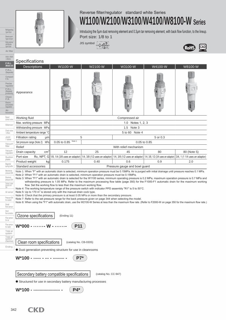
Reverse filter/regulator standard white Series
W1100/W2100/W3100/W4100/W8100-W SeriesIntroducing the 5µm dust removing element and 0.3µm tar removing element, with back flow function, to the lineup. Port size: 1/8 to 1
Specifications
Note 1: When "F" with an automatic drain is selected, minimum operation pressure must be 0.15MPa. Air is purged with initial drainage until pressure reaches 0.1 MPa.Note 2: When "F1" with an automatic drain is selected, minimum operation pressure must be 0.15MPa. Note 3: When "F1" with an automatic drain is selected for the W1100 series, minimum operating pressure is 0.2 MPa, maximum operation pressure is 0.7 MPa and
withstanding pressure is 1.05 MPa. Refer to the maximum processing flow table (page 350) for the F1000-F1 automatic drain for the maximum working flow. Set the working flow to less than the maximum working flow.
Note 4: The working temperature range of the pressure switch with indicator PPD assembly "R1" is 5 to 50°C. Note 5: Up to 170 m3 is stored only with the manual drain cock type. Note 6: Check that the primary pressure is at least 0.05 MPa or more than the secondary pressure. Note 7: Refer to the set pressure range for the back pressure given on page 344 when selecting the model. Note 8: When using the "F1" with automatic drain, use the W2100-W Series at less than the maximum flow rate. (Refer to F2000-W on page 350 for the maximum flow rate.)
Descriptions W1100-W W2100-W W3100-W W4100-W W8100-W
Appearance
Working fluid Compressed airMax. working pressure MPa 1.0 Notes 1, 2, 3Withstanding pressure MPa 1.5 Note 3Ambient temperature range °C 5 to 60 Note 4Filtration rating µm 5 5 or 0.3Set pressure range (Note 2) MPa 0.05 to 0.85 Note 1 0.05 to 0.85Relief With relief mechanismDrain capacity cm3 12 25 45 80 80 (Note 5)Port size Rc, NPT, G 1/8, 1/4 (3/8 uses an adaptor) 1/4, 3/8 (1/2 uses an adaptor) 1/4, 3/8 (1/2 uses an adaptor) 1/4, 3/8, 1/2 (3/4 uses an adaptor) 3/4, 1 (1 1/4 uses an adaptor)Product weight kg 0.175 0.40 0.6 0.9 2.0Standard accessories Pressure gauge and bowl guard
Ozone specifications (Ending 11)
P11W*000 - · · · · · · - W - · · · · · · -
● Dust generation preventing structure for use in cleanrooms
Clean room specifications (catalog No. CB-033S)
P7*W*100 - ······ - ··· - ········· -
P4*W*100 - ····················· -
● Structured for use in secondary battery manufacturing processes
Secondary battery compatible specifications (catalog No. CC-947)
JIS symbol
342
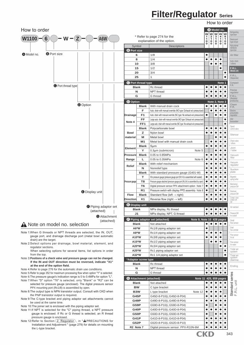
Filter/Regulator SeriesHow to order
Attachment (attached)
G
Note on model no. selectionNote 1: When G threads or NPT threads are selected, the IN, OUT,
gauge port, and drainage discharge port (metal bowl automatic drain) are the target.
Note 2: Select options per drainage, bowl material, element, and regulator sections.
When selecting options for several items, list options in order from the top.
Note 3: Positions of a check valve and pressure gauge can not be changed. If the IN and OUT direction must be reversed, indicate "X1"
at the end of the option field. Note 4: Refer to page 276 for the automatic drain use conditions. Note 5: Refer to page 352 for maximum processing flow when option "Y" is selected.Note 6: The pressure gauge's indication range is 0 to 0.4MPa for option "L".Note 7: When "D" option "T6" is selected, only "Blank" or "R2" can be
selected for pressure gauge (enclosed). The digital pressure sensor PPX mounting port (Rc1/8) is assembled by open.
Note 8: The output type is NPN transistor output. Consult with CKD when the PNP transistor output is required.
Note 9: The C-type bracket and piping adaptor set attachments cannot be used at the same time.
Note 10: The joiner set is enclosed with the piping adaptor set. Note 11: If NPT is selected for the "C" piping thread, a NPT pressure
gauge is enclosed. If Rc or G thread is selected, an R thread pressure gauge is enclosed.
Note 12: Refer to Section 2. Regulator , in " PRECAUTIONS for Installation and Adjustment " (page 279) for details on mounting the L-type bracket.
Piping adaptor set (attached)
F
Port sizeBModel no.A
Port thread typeC
OptionD
Display unitE
6W1100 6 W Z A6W
Model no.W1100
W2100
W3100
W4100
W8100
Symbol DescriptionsPort size
6 1/8 ●
8 1/4 ● ● ● ●
10 3/8 ● ● ●
15 1/2 ●
20 3/4 ●
25 1 ●
Port thread type Note 1Blank Rc thread ● ● ● ● ●
N NPT thread ● ● ● ● ●
G G thread ● ● ● ● ●
Option Note 2, Note 3
Drainage
Note 4
Blank With manual drain cock ● ● ● ● ●
F Auto. drain with manual override (NO type: Exhaust w/o pressurized) ● ● ● ●
F1 Auto. drain with manual override (NC type: No exhaust w/o pressurized) ● ● ● ●
FF Large auto. drain with manual override (NO type: Exhaust w/o pressurized) ●
FF1 Large auto. drain with manual override (NC type: No exhaust w/o pressurized) ●
Bowl material
Blank Polycarbonate bowl ● ● ● ● ●
Z Nylon bowl ● ● ● ● ●
M Metal bowl ● ● ●
M1 Metal bowl with manual drain cock ● ● ● ●
ElementBlank 5μm ● ● ● ● ●
Y 0.3μm (submicron) Note 5 ● ● ●
PressureRange
Blank 0.05 to 0.85MPa ● ● ● ● ●
L 0.05 to 0.35MPa Note 6 ● ● ● ● ●
ReliefBlank With relief mechanism ● ● ● ● ●
N Nonrelief type ● ● ● ● ●
Pressure gauge
Blank With standard pressure gauge (G401-W) ● ● ● ● ●
T W/o pressure gauge (pressure gauge port (Rc1/4) is assembled with sealed) ● ● ● ● ●
T8 Pressure gauge attached (pressure gauge port (Rc1/4) is assembled by open) ● ● ● ● ●
T6 Digital pressure sensor PPX attachment option Note 7 ● ● ● ● ●
R1 Pressure switch with display PPD assembly Note 8 ● ● ● ●
FlowDirection
Blank Standard flow (left → right) ● ● ● ● ●
X1 Reverse flow (right → left) ● ● ● ● ●
Display unitBlank MPa display, Rc thread ● ● ● ● ●
J1 MPa display, NPT, G thread ● ● ● ● ●
Piping adaptor set (attached) Note 9, Note 10 428 pagesBlank Not attached ● ● ● ● ●
A6*W Rc1/8 piping adaptor set ●
A8*W Rc1/4 piping adaptor set ● ● ● ●
A10*W Rc3/8 piping adaptor set ● ● ● ●
A15*W Rc1/2 piping adaptor set ● ● ●
A20*W Rc3/4 piping adaptor set ● ●
A25*W Rc1 piping adaptor set ●
A32*W Rc1 1/4 piping adaptor set ●
*Adaptor screw typeBlank Rc thread ● ● ● ● ●
N NPT thread ● ● ● ● ●
G G thread ● ● ● ● ●
Attachment (attached) Note 11 425, 659 pagesBlank Not attached ● ● ● ● ●
BW C type bracket ● ● ● ● ●
B3W L type bracket Note 12 ● ● ● ●
G45P G45D-8-P10(L:G45D-8-P04) ● ● ● ● ●
G49P G49D-8-P10(L:G49D-8-P04) ● ● ● ● ●
G59P G59D-8-P10(L:G59D-8-P04) ● ● ● ●
G40P G40D-8-P10(L:G40D-8-P04) ● ● ● ● ●
G50P G50D-8-P10(L:G50D-8-P04) ● ● ● ●
G41P G41D-8-P10(L:G41D-8-P04) ● ● ● ● ●
G52P G52D-8-P10(L:G52D-8-P10) ● ● ● ● ●
R2 Note 7 Digital pressure sensor: PPX-R10N-6M ● ● ● ● ●
G
A
F
E
D
C
B
* Refer to page 274 for the explanation of the option.
343
How to order
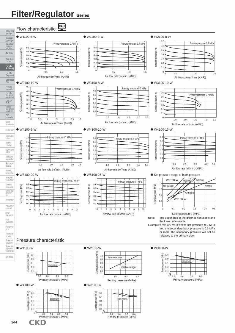
Flow characteristic● W1100-6-W ● W1100-8-W ● W2100-8-W
● W3100-10-W
● W4100-15-W
● Set pressure range to back pressure
● W4100-8-W ● W4100-10-W
● W8100-20-W ● W8100-25-W
Note: The upper side of the graph is nonusable and the lower side usable.
Example: If W4100-W is set to set pressure 0.2 MPa and the secondary back pressure is 0.6 MPa or more, the secondary pressure will not be released to the primary side.
Pressure characteristic● W1100-W ● W2100-W ● W3100-W
Filter/Regulator Series
● W3100-8-W● W2100-10-W
● W4100-W ● W8100-W
344
Secon
dary p
ressur
e (MP
a)Se
condar
y pres
sure (
MPa)
Secon
dary p
ressur
e (MP
a)Se
condar
y pres
sure (
MPa)
Secon
dary p
ressur
e (MP
a)Se
condar
y pres
sure (
MPa)
Secon
dary p
ressur
e (MP
a)Se
condar
y pres
sure (
MPa)
Secon
dary p
ressur
e (MP
a)Se
condar
y pres
sure (
MPa)
Secon
dary p
ressur
e (MP
a)
0.6
0.5
0.4
0.3
0.2
0.1
00.5 1.0 1.5
Air flow rate (m3/min. (ANR))
Primary pressure 0.7 MPa0.6
0.5
0.4
0.3
0.2
0.1
00.5 1.0 1.5
Air flow rate (m3/min. (ANR))
Primary pressure 0.7 MPa
0.5
0.4
0.3
0.2
0.1
01.0 2.0 2.5
Air flow rate (m3/min. (ANR))
Primary pressure 0.7 MPa
Air flow rate (m3/min. (ANR))
Primary pressure 0.7 MPa
Air flow rate (m3/min. (ANR))
Primary pressure 0.7 MPa
0.6
0.5
0.4
0.3
0.2
0.1
01.0 2.0 5.0
Air flow rate (m3/min. (ANR))
Primary pressure 0.7 MPa
0.6
0.5
0.4
0.3
0.2
0.1
01.0 3.0 5.0
Air flow rate (m3/min. (ANR))
Primary pressure 0.7 MPa
Air flow rate (m3/min. (ANR))
Primary pressure 0.7 MPa
Air flow rate (m3/min. (ANR))
Primary pressure 0.7 MPa
2.0 4.0
0.6
0.5
0.4
0.3
0.2
0.1
0 1 3 102 9
0.6
0.5
0.4
0.3
0.2
0.1
3.0 4.0
0.6
0.5
0.4
0.3
0.2
0.1
00.5 1.5 2.51.0 2.0
0.6
0.5
0.4
0.3
0.2
0.1
01.0 3.0 5.02.0 4.0
1.50.5
0.6
4 5 6 7 8 0 1 3 102 94 5 6 7 8
0.8
0.6
0.4
0.2
0 0.1 0.3 0.5
Setting pressure (MPa)
W3100-W
0.2 0.4
1 W1100-W W4100-W
W8100-W
Available
Not available
0.24
0.22
0.2
0.18
0.16
0.2 0.6
Primary pressure (MPa)
Setting pressure
0.4 0.8
0.24
0.22
0.2
0.18
0.16
0.2 0.6Primary pressure (MPa)
Setting pressure
0.4 0.80
0.21
0.2
0.19
0.18
0.17
0.2 0.6Primary pressure (MPa)
Setting pressure
0.4 0.80
0.21
0.2
0.19
0.18
0.17
0.2 0.6Primary pressure (MPa)
Setting pressure
0.4 0.80
W2100-W
1.00.8
0.6
0.4
0.2
0.1 0.30.20
Setting pressure (MPa)
Non-usable range
Usable range
0.6
0.5
0.4
0.3
0.2
0.1
0
0.7
0.50 1 1.5 2 2.5 3
Primary pressure 0.7 MPa
Air flow rate (m3/min. (ANR))
0.6
0.5
0.4
0.3
0.2
0.1
0
0.7
0.50 1 1.5 2 2.5
Primary pressure 0.7 MPa
Air flow rate (m3/min. (ANR))
Secon
dary p
ressur
e (MP
a)Se
condar
y pres
sure (
MPa)
Secon
dary b
ack pre
ssure (
MPa)
Secon
dary p
ressur
e (MP
a)
Secon
dary p
ressur
e (MP
a)
Secon
dary p
ressur
e (MP
a)

No. Parts nameMaterial
W1100-W W2100-W W3100-W W4100-W W8100-W1 Plate cover ABS resin - ABS resin
2 Body Polyamide resin, steel Aluminum alloy die-casting
3 O ring Special nitrile rubber
4 Element Polyacetal resinPolypropylene Polypropylene
5 Diaphragm assembly Polyacetal resinNitrile rubber Zinc alloy die-casting, nitrile rubber
6 Cover Polyamide resin PBT resin Aluminum alloy die-casting
7 Knob Polyacetal resin
8 Valve assembly Brass, hydrogen nitrile rubber (polyacetal resin: W2100-W, W3100-W, 4100-W)
9 Pressure gauge assembly PBT resin, polyacetal resin, polycarbonate resin, nitrile rubber, brass, steel
10 Check valve total assembly PBT resin, nitrile rubber, stainless steel wire, steel
11 Bowl assembly Polycarbonate resin, polyacetal resin, urethane resin
12 Bowl guard Polyamide resin Polyamide resin, steel
Note 1: W1100-W is element assembly. Note 2: O-ring of W1000-W is special shaped. Note 3: Refer to page 349 for repair kits model No.
Note 2
Note 1
Functional explanationWhen the primary pressure is introduced from the IN side, the check valve functions as a regular regulator because it closes with primary pressure and spring load. When primary pressure is released by a switching valve such as a shut-off valve, the check valve opens with secondary pressure. Pressure in the diaphragm chamber is released and pressure drops. This causes the diaphragm to be pressed down by the pressure adjustment spring. The main valve (valve assembly) opens, and the air on the OUT side is discharged. Note: Set back pressure A for when the primary pressure is released within the
range in the graph for the regulator's set pressure. (Refer to page 344 for the graph)
● Circuit diagram
When using shut-off valve in front of reverse filter and regulator.
Internal structure and parts list● W1100-W ● W2100-W
● W8100-W
Filter/Regulator SeriesInternal structure and parts list
● W3100-W/W4100-W
345
IN OUT
Shut-off valve
OUTEXHIN A
4
2
6
7
3
11
12
8
5
1
910
4
2
6
7
3
11
12
8
51
9
10
IN OUT
4
2
6
7
3
11
12
85
1
9
10
IN OUT
7
6
5
2
3
4
11
12
8
9 10
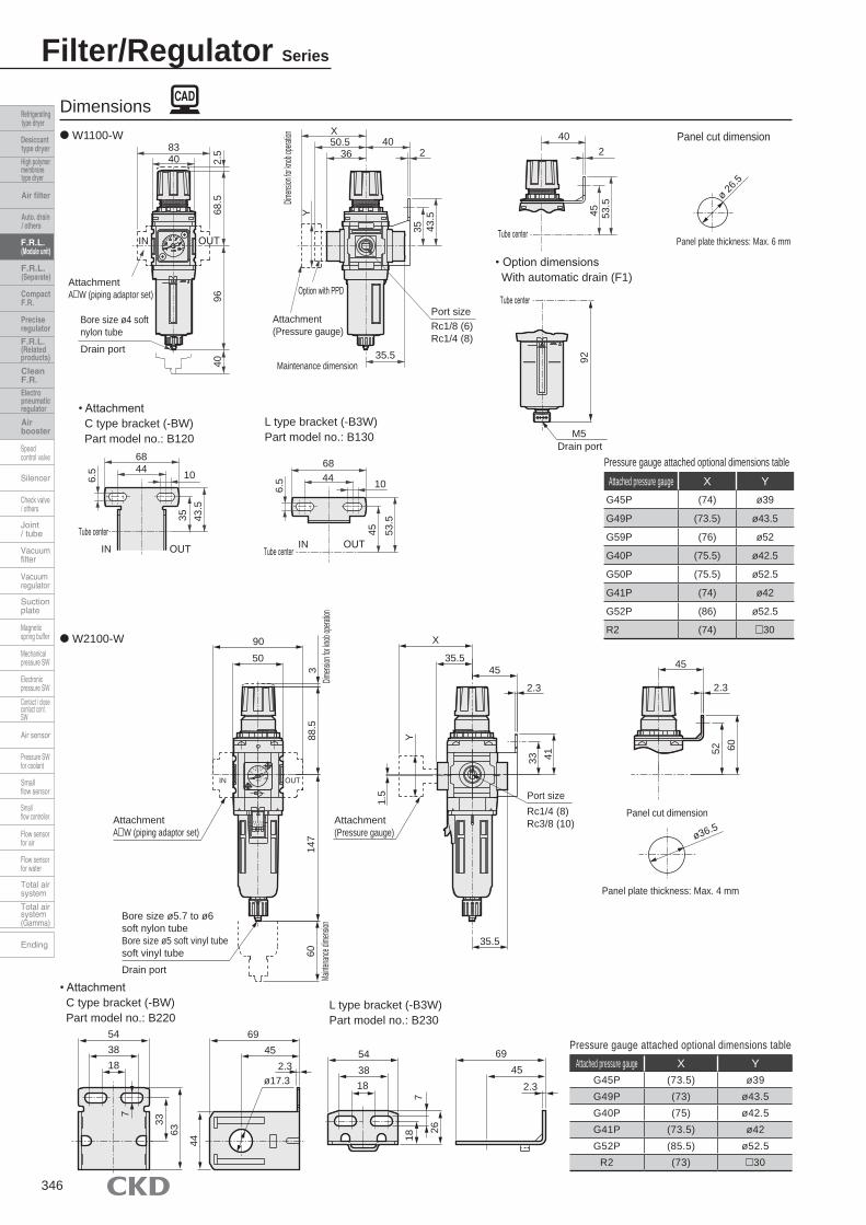
Attached pressure gauge X YG45P (74) ø39
G49P (73.5) ø43.5
G59P (76) ø52
G40P (75.5) ø42.5
G50P (75.5) ø52.5
G41P (74) ø42
G52P (86) ø52.5
R2 (74) 30
Pressure gauge attached optional dimensions table
Filter/Regulator Series
Dimensions● W1100-W Panel cut dimension
• AttachmentC type bracket (-BW)Part model no.: B120
L type bracket (-B3W)Part model no.: B130
• Option dimensionsWith automatic drain (F1)
● W2100-W
L type bracket (-B3W)Part model no.: B230
Attached pressure gauge X YG45P (73.5) ø39G49P (73) ø43.5G40P (75) ø42.5G41P (73.5) ø42G52P (85.5) ø52.5
R2 (73) 30
Pressure gauge attached optional dimensions table
• AttachmentC type bracket (-BW)Part model no.: B220
346
40
Option with PPD
Attachment (Pressure gauge)
Maintenance dimension
Port sizeRc1/8 (6)Rc1/4 (8)
35.5
Bore size ø4 soft nylon tube
Drain port
AttachmentA W (piping adaptor set)
IN OUT
83
Dimens
ion for
knob
operati
on
40
9668
.52.
5
Y
X50.5
3640
2
43.5
35
Tube center
IN OUT
Tube center
2
45 53.5
68
43.5
35
1044
6.5
Tube centerIN OUT
68
53.5
45
1044
6.5
Panel plate thickness: Max. 6 mm
ø 26.5
40
Tube center
92
M5Drain port
X
35.545
2.3
88.5
45
2.3
52 60
AttachmentA W (piping adaptor set)
9050
IN OUT
3Dim
ension
for kn
ob ope
ration
147
60Ma
intenan
ce dim
ension
Attachment(Pressure gauge)
Port sizeRc1/4 (8)Rc3/8 (10)
35.5
1.5
Y
33 41
Bore size ø5.7 to ø6 soft nylon tubeBore size ø5 soft vinyl tubesoft vinyl tubeDrain port
54 69
6333
Panel cut dimension
ø36.5
Panel plate thickness: Max. 4 mm
3818
452.3
ø17.3
44
543818
187
26
6945
2.3
7

Filter/Regulator SeriesDimensions
Dimensions● W3100-W
Attached pressure gauge X YG45P (75) ø39
G49P (74.5) ø43.5
G59P (77) ø52
G40P (76.5) ø42.5
G50P (76.5) ø52.5
G41P (75) ø42
G52P (86) ø52.5
R2 (75) 30
Pressure gauge attached optional dimensions table
● W4100-W
Panel cut dimension
• AttachmentC type bracket (-BW)Part model no.: B420
L type bracket (-B3W)Part model no.: B430
● For the plastic bowl, the dimensions of the manual cock and the automatic drain are same.
Attached pressure gauge X YG45P (70) ø39
G49P (69.5) ø43.5
G59P (72) ø52
G40P (71.5) ø42.5
G50P (71.5) ø52.5
G41P (70) ø42
G52P (82) ø52.5
R2 (69.5) 30
• AttachmentC type bracket (-BW)Part model no.: B320
L type bracket (-B3W)Part model no.: B330
● For the plastic bowl, the dimensions of the manual cock and the automatic drain are same.
347
55
Option with PPD
Attachment (Pressure gauge)
Maintenance dimension
Port sizeRc1/4 (8)Rc3/8 (10)Rc1/2 (15)
39.5
Bore size ø5.7 to ø6 soft nylon tubeBore size ø5 soft vinyl tubeDrain port
AttachmentA W (piping adaptor set)
IN OUT
120Rc3/4:130
Dimens
ion for
knob
operati
on
80
171
110
3
Y
X51.5(42.5)
55
2.3
53.5
45
Tube centerIN OUT
Tube center
2.3
58 66.5
84
53.5
45
1455
7
Tube center IN OUT
55
66.5
58
14
84
7
Panel plate thickness: Max. 7 mm
ø47
60
2.5
Pressure gauge attached optional dimensions table
Panel cut dimension
45
Option with PPD
Attachment (Pressure gauge)
Maintenance dimension
Port sizeRc1/4 (8)Rc3/8 (10)
31.5
Bore size ø5.7 to ø6 soft nylon tubeBore size ø5 soft vinyl tube
Drain port
AttachmentA W (piping adaptor set)
IN OUT
103
Dimens
ion for
knob
operati
on
63
148
104
3
Y
X46.5(34.5)
45
2.3
53.5
45
Tube centerIN OUT
Tube center
2.3
7263
.5
67
53.5
45
16.534.5
7
Tube center IN OUT
67
63.5
72
16.534.5
7Panel plate thickness: Max. 4 mm
ø40
60
2.5
Filter/Regulator Series
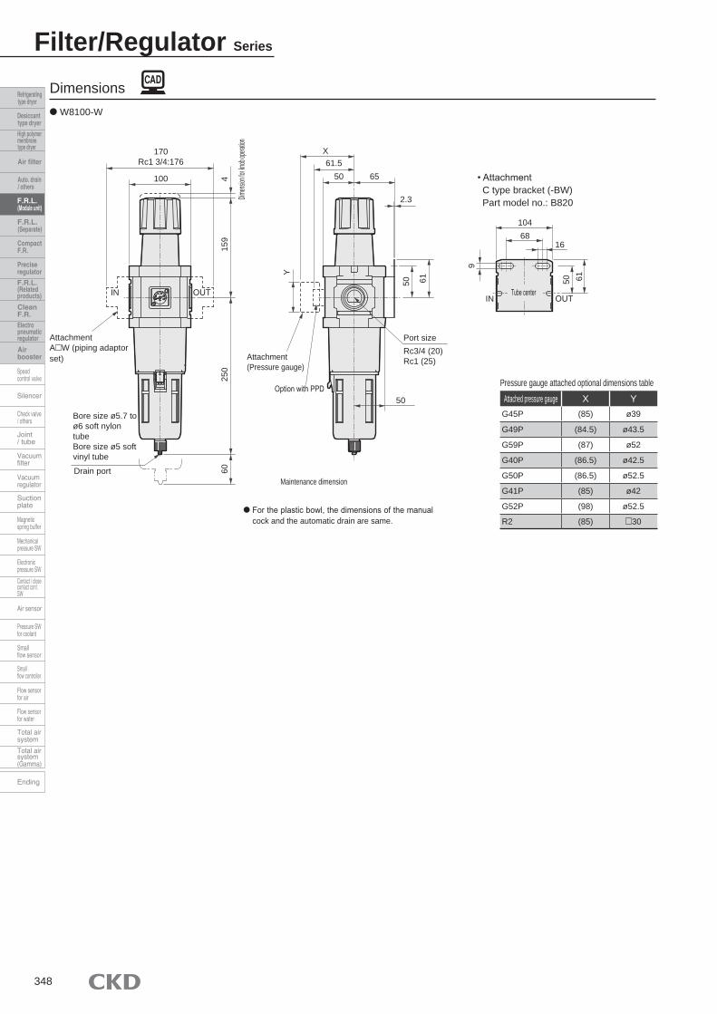
Dimensions● W8100-W
Attached pressure gauge X YG45P (85) ø39
G49P (84.5) ø43.5
G59P (87) ø52
G40P (86.5) ø42.5
G50P (86.5) ø52.5
G41P (85) ø42
G52P (98) ø52.5
R2 (85) 30
Pressure gauge attached optional dimensions table
• AttachmentC type bracket (-BW)Part model no.: B820
● For the plastic bowl, the dimensions of the manual cock and the automatic drain are same.
348
IN OUT
104
6150
1668
9
Attachment (Pressure gauge)
Bore size ø5.7 to ø6 soft nylon tubeBore size ø5 soft vinyl tube
Drain port
AttachmentA W (piping adaptor set)
IN OUT
170Rc1 3/4:176
Dimens
ion for
knob
operati
on
100
250
159
460
Option with PPD
Maintenance dimension
Port sizeRc3/4 (20)Rc1 (25)
50
Y
X
50 65
2.3
6150
61.5
Tube center
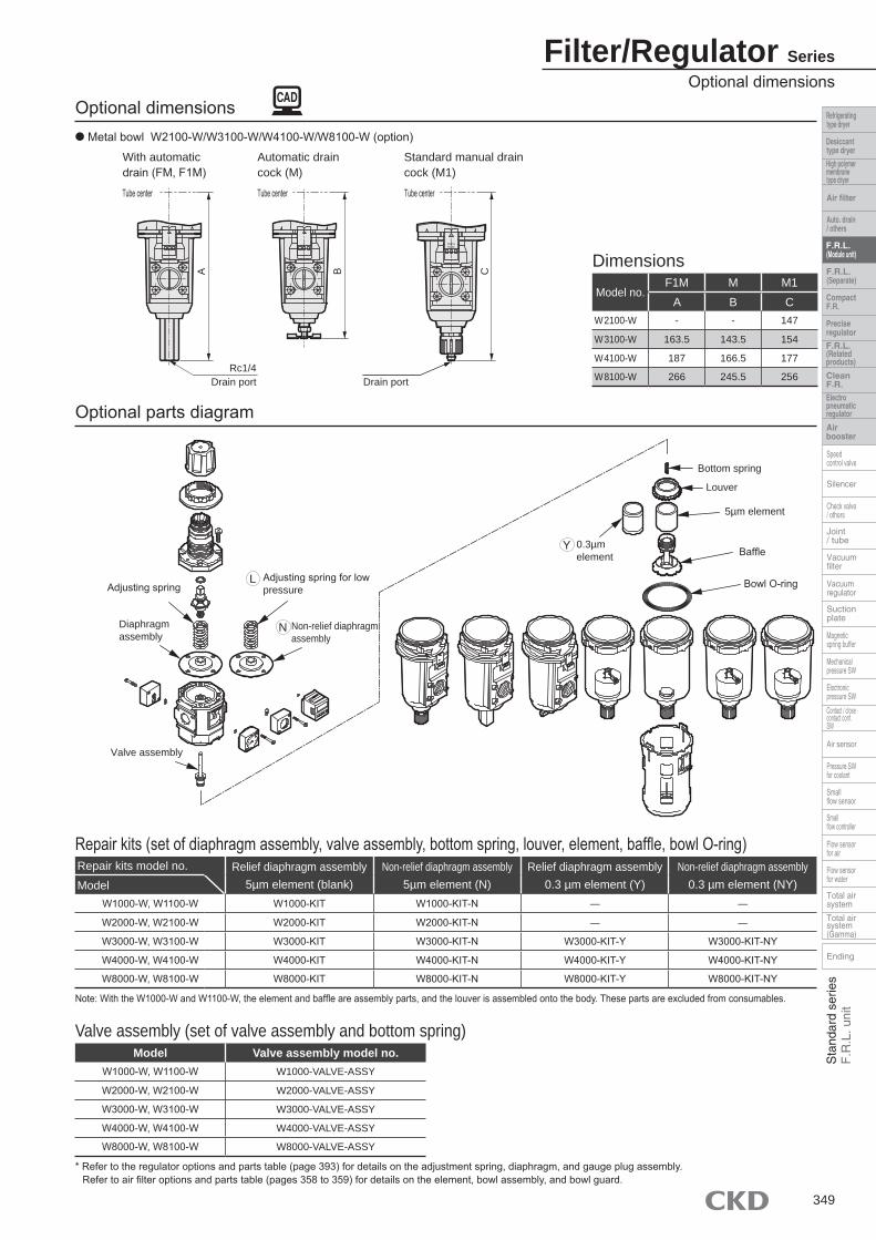
Model no.F1M M M1
A B CW2100-W - - 147
W3100-W 163.5 143.5 154
W4100-W 187 166.5 177
W8100-W 266 245.5 256
Dimensions
Repair kits model no. Relief diaphragm assembly5µm element (blank)
Non-relief diaphragm assembly5µm element (N)
Relief diaphragm assembly0.3 µm element (Y)
Non-relief diaphragm assembly0.3 µm element (NY)Model
W1000-W, W1100-W W1000-KIT W1000-KIT-N ― ―
W2000-W, W2100-W W2000-KIT W2000-KIT-N ― ―
W3000-W, W3100-W W3000-KIT W3000-KIT-N W3000-KIT-Y W3000-KIT-NY
W4000-W, W4100-W W4000-KIT W4000-KIT-N W4000-KIT-Y W4000-KIT-NY
W8000-W, W8100-W W8000-KIT W8000-KIT-N W8000-KIT-Y W8000-KIT-NY
Model Valve assembly model no.W1000-W, W1100-W W1000-VALVE-ASSY
W2000-W, W2100-W W2000-VALVE-ASSY
W3000-W, W3100-W W3000-VALVE-ASSY
W4000-W, W4100-W W4000-VALVE-ASSY
W8000-W, W8100-W W8000-VALVE-ASSY
Repair kits (set of diaphragm assembly, valve assembly, bottom spring, louver, element, baffle, bowl O-ring)
Note: With the W1000-W and W1100-W, the element and baffle are assembly parts, and the louver is assembled onto the body. These parts are excluded from consumables.
Valve assembly (set of valve assembly and bottom spring)
* Refer to the regulator options and parts table (page 393) for details on the adjustment spring, diaphragm, and gauge plug assembly. Refer to air filter options and parts table (pages 358 to 359) for details on the element, bowl assembly, and bowl guard.
Optional dimensions● Metal bowl W2100-W/W3100-W/W4100-W/W8100-W (option)
Optional parts diagram
Filter/Regulator SeriesOptional dimensions
349
ERPSS
NRUT
With automatic drain (FM, F1M)
Automatic drain cock (M)
Tube center Tube center
Drain portRc1/4
A B
Adjusting springAdjusting spring for low pressure
Diaphragm assembly
Valve assembly
0.3µmelement
Bottom spring
Non-relief diaphragm assembly
Louver
5µm element
Baffle
Bowl O-ringL
N
Y
Tube center
Standard manual drain cock (M1)
C
Drain port
Element
Air Filter Series
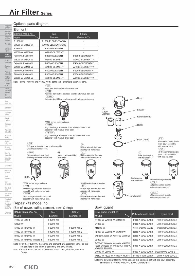
Optional parts diagram
Repair kits model no.(Set of louver, baffle, element, bowl O-ring)Repair kits model no. 5µm
Element0.3µm
Element (Y)ModelF1000-W Note 1 F1000-KIT -
F2000-W F2000-KIT -
F3000-W, FM3000-W F3000-KIT F3000-KIT-Y
F4000-W, FM4000-W F4000-KIT F4000-KIT-Y
F6000-W, FM6000-W F6000-KIT F6000-KIT-Y
F8000-W, FM8000-W Note 2 F8000-KIT F8000-KIT-Y
Note 1: For the F1000-W, the baffle and element are assembly parts, so the set consists of the element assembly and bowl O-ring.
Note 2: For the F8000-W, the set consists of the baffle, element, and bowl O-ring.
Bowl guardBowl guard model no.
Polycarbonate bowl Nylon bowlModelF1000-W, W1000-W, W1100-W F1000-W-BOWL-GUARD F1000-W-BOWL-GUARD-Z
L1000-W L1000-W-BOWL-GUARD L1000-W-BOWL-GUARD-Z
M1000-W M1000-W-BOWL-GUARD M1000-W-BOWL-GUARD-Z
F2000-W, W2000-W, W2100-W F2000-W-BOWL-GUARD F2000-W-BOWL-GUARD-Z
W3100-W, F3000-W, W3000-W, M3000-W F3000-W-BOWL-GUARD F3000-W-BOWL-GUARD-Z
L3000-W L3000-W-BOWL-GUARD L3000-W-BOWL-GUARD-ZF4000-W, W4000-W, M4000-W, W4100-W, F6000-W M6000-W, W8100-W, F8000-W, W8000-W, M8000-W
F4000-W-BOWL-GUARD F4000-W-BOWL-GUARD-Z
L4000-W, L8000-W L4000-W-BOWL-GUARD L4000-W-BOWL-GUARD-Z
W8100-W, F8000-W, W8000-W-FF, FF1 DT4000-W-BOWL-GUARD DT4000-W-BOWL-GUARD-Z
Note: The bowl guard for the 1000 Series F1 is sold as a set with the bowl assembly. The model is "F1000-W-BOWL-BOWL-GUARD-F1".
Element model no. 5µmElement
0.3µmElement (Y)Model
F1000-W F1000-ELEMENT-ASSY -
W1000-W, W1100-W W1000-ELEMENT-ASSY -
F2000-W F2000-ELEMENT -
W2000-W, W2100-W W2000-ELEMENT -
F3000-W, FM3000-W F3000-ELEMENT F3000-ELEMENT-Y
W3000-W, W3100-W W3000-ELEMENT W3000-ELEMENT-Y
F4000-W, FM4000-W F4000-ELEMENT F4000-ELEMENT-Y
W4000-W, W4100-W W4000-ELEMENT W4000-ELEMENT-Y
F6000-W, FM6000-W F6000-ELEMENT F6000-ELEMENT-Y
F8000-W, FM8000-W F8000-ELEMENT F8000-ELEMENT-Y
W8000-W, W8100-W W8000-ELEMENT W8000-ELEMENT-Y
Note: For the F1000-W and W1000-W, the baffle and element are assembly parts.
358
ERPSS
NRUT
Body
Louver
5µm element
Baffle
Bowl O-ring
0.3µmElement
Y
NO type automatic drain bowl assembly with manual cock
F
Metal bowl assembly with cock
M
NO type automatic drain bowl assembly with metal manual cock
FM
NC type automatic drain bowl assembly with metal manual cock
F1M
Rc1/4
*8000 series large emission
NO type large automatic drain bowl assembly with metal manual cock
FFM
NC type large automatic drain bowl assembly with metal manual cock
FF1M
NO type large automatic drain bowl assembly with manual cock
FF*8000 series large emission
NC type large automatic drain bowl assembly with manual cock
FF1
NO type large automatic drain nylon bowl assembly with manual cock
FFZ*8000 series large emission
NC type large automatic drain nylon bowl assembly with manual cock
FF1Z
Bowl guard
Bowl assembly with manual cock
NO type automatic drain nylon bowl assembly with manual cock
FZ
NC type automatic drain nylon bowl assembly with manual cock
F1Z
Nylon bowl assembly with manual cock
ZNC type automatic drain bowl assembly with manual cock
F1
*8000 series large emission
High discharge automatic drain NO type metal bowl assembly with manual drain cock
FFM1
High discharge automatic drain NC type metal bowl assembly with manual drain cock
FF1M1
Metal bowl assembly with manual drain cockM1
Automatic drain NO type metal bowl assembly with manual drain cockFM1
Automatic drain NC type metal bowl assembly with manual drain cockF1M1
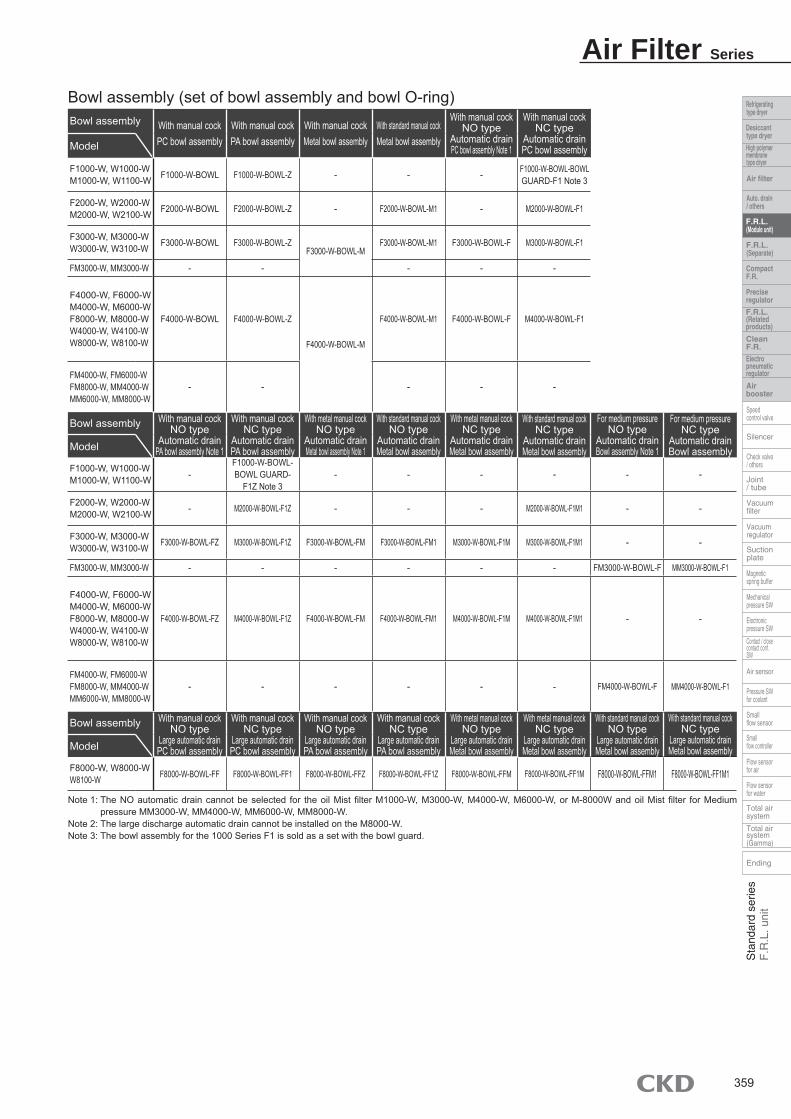
Bowl assembly (set of bowl assembly and bowl O-ring)Bowl assembly With manual cock
PC bowl assemblyWith manual cockPA bowl assembly
With manual cockMetal bowl assembly
With standard manual cockMetal bowl assembly
With manual cockNO type
Automatic drainPC bowl assembly Note 1
With manual cockNC type
Automatic drainPC bowl assemblyModel
F1000-W, W1000-WM1000-W, W1100-W F1000-W-BOWL F1000-W-BOWL-Z - - - F1000-W-BOWL-BOWL
GUARD-F1 Note 3
F2000-W, W2000-WM2000-W, W2100-W F2000-W-BOWL F2000-W-BOWL-Z - F2000-W-BOWL-M1 - M2000-W-BOWL-F1
F3000-W, M3000-WW3000-W, W3100-W F3000-W-BOWL F3000-W-BOWL-Z
F3000-W-BOWL-MF3000-W-BOWL-M1 F3000-W-BOWL-F M3000-W-BOWL-F1
FM3000-W, MM3000-W - - - - -
F4000-W, F6000-WM4000-W, M6000-WF8000-W, M8000-WW4000-W, W4100-WW8000-W, W8100-W
F4000-W-BOWL F4000-W-BOWL-Z
F4000-W-BOWL-M
F4000-W-BOWL-M1 F4000-W-BOWL-F M4000-W-BOWL-F1
FM4000-W, FM6000-WFM8000-W, MM4000-WMM6000-W, MM8000-W
- - - - -
Bowl assembly With manual cockNO type
Automatic drainPA bowl assembly Note 1
With manual cockNC type
Automatic drainPA bowl assembly
With metal manual cockNO type
Automatic drainMetal bowl assembly Note 1
With standard manual cockNO type
Automatic drainMetal bowl assembly
With metal manual cockNC type
Automatic drainMetal bowl assembly
With standard manual cockNC type
Automatic drainMetal bowl assembly
For medium pressureNO type
Automatic drainBowl assembly Note 1
For medium pressureNC type
Automatic drainBowl assemblyModel
F1000-W, W1000-WM1000-W, W1100-W -
F1000-W-BOWL-BOWL GUARD-
F1Z Note 3- - - - - -
F2000-W, W2000-WM2000-W, W2100-W - M2000-W-BOWL-F1Z - - - M2000-W-BOWL-F1M1 - -
F3000-W, M3000-WW3000-W, W3100-W F3000-W-BOWL-FZ M3000-W-BOWL-F1Z F3000-W-BOWL-FM F3000-W-BOWL-FM1 M3000-W-BOWL-F1M M3000-W-BOWL-F1M1 - -
FM3000-W, MM3000-W - - - - - - FM3000-W-BOWL-F MM3000-W-BOWL-F1
F4000-W, F6000-WM4000-W, M6000-WF8000-W, M8000-WW4000-W, W4100-WW8000-W, W8100-W
F4000-W-BOWL-FZ M4000-W-BOWL-F1Z F4000-W-BOWL-FM F4000-W-BOWL-FM1 M4000-W-BOWL-F1M M4000-W-BOWL-F1M1 - -
FM4000-W, FM6000-WFM8000-W, MM4000-WMM6000-W, MM8000-W
- - - - - - FM4000-W-BOWL-F MM4000-W-BOWL-F1
Bowl assembly With manual cockNO type
Large automatic drainPC bowl assembly
With manual cockNC type
Large automatic drainPC bowl assembly
With manual cockNO type
Large automatic drainPA bowl assembly
With manual cockNC type
Large automatic drainPA bowl assembly
With metal manual cockNO type
Large automatic drainMetal bowl assembly
With metal manual cockNC type
Large automatic drainMetal bowl assembly
With standard manual cockNO type
Large automatic drainMetal bowl assembly
With standard manual cockNC type
Large automatic drainMetal bowl assemblyModel
F8000-W, W8000-WW8100-W F8000-W-BOWL-FF F8000-W-BOWL-FF1 F8000-W-BOWL-FFZ F8000-W-BOWL-FF1Z F8000-W-BOWL-FFM F8000-W-BOWL-FF1M F8000-W-BOWL-FFM1 F8000-W-BOWL-FF1M1
Note 1: The NO automatic drain cannot be selected for the oil Mist filter M1000-W, M3000-W, M4000-W, M6000-W, or M-8000W and oil Mist filter for Medium pressure MM3000-W, MM4000-W, MM6000-W, MM8000-W.
Note 2: The large discharge automatic drain cannot be installed on the M8000-W. Note 3: The bowl assembly for the 1000 Series F1 is sold as a set with the bowl guard.
Air Filter Series
359


![W3000 [º¸´Ù ÀÌÅÂ/¿µ]Ç¥Áö](https://img.pdfslide.net/doc/110x75/61d81cda54b0c70dda5e4579/w3000-.jpg)


![Westec Security - W3000 User Manual[2]](https://img.pdfslide.net/doc/110x75/55247ad94a7959a7488b47c8/westec-security-w3000-user-manual2.jpg)
![W3000 제품제안서.ppt [호환 모드]](https://img.pdfslide.net/doc/110x75/61d822f22c475935df509188/w3000-ppt-.jpg)