Embed Size (px)
Citation preview
Conference Organizers
AGH University of Science and Technology
Faculty of Mechanical Engineering and Robotics
Department of Process Control
Committee on Machine Building
of the Polish Academy of Science
13th Conference on
Active Noise and Vibration
Control Methods
MARDiH
Proceedings
Krakow – Kazimierz Dolny, Poland
12-14 June 2017
This publication contains the abstracts of the papers selected by the Scientific Board of the
Conference on Active Noise and Vibration Control Methods Conference. Full papers, however,
will be published in indexed scientific journals, after positive review.
Editor: Marcin Apostoł - AGH University of Science and Technology
Publisher: Department of Process Control
AGH University of Science and Technology
Printed by:
DELTA Jarosław A. Jagła tel. +48 601 68 25 00
ISBN: 978-83-64755-08-8

Program committee:
Chairman:
Piotr Cupiał
Honorary chairman:
Janusz Kowal
Members
Jan Awrejcewicz Wiesław Ostachowicz
Jerzy Bajkowski Marek Pawełczyk
Stephen P. Banks Stanisław Pietrzko
Wojciech Batko Delf Sachau
Marian W. Dobry Bogdan Sapiński
Stefan Domek Andrzej Seweryn
Janusz Gołdasz Zbigniew Starczewski
Zdzisław Gosiewski Jacek Snamina
Colin Hansen Eugeniusz Świtoński
Jan Holnicki-Szulc Ryszard Tadeusiewicz
Krzysztof Kaliński Osman Tokhi
Marek Książek Jiri Tuma
Zi-Qiang Lang Andrzej Tylikowski
Lucyna Leniowska Tadeusz Uhl
Arkadiusz Mężyk Wiesław Wszołek
Józef Nizioł
Organizing committee:
Chairman:
Agata Nawrocka
Members:
Marcin Apostoł Roman Ornacki
Stanisław Flaga Marcin Węgrzynowski
Mateusz Kozioł Kamil Zając
Preface
Ladies and Gentlemen,
Following more than 20 years’ tradition, we are meeting again at the
Conference on Active Noise and Vibration Control Methods. Our aim is to
present the results of recent research work, to exchange ideas and to share
experience among the participants from research centres in Poland and abroad.
The control of low frequency noise and vibration has always been a
difficult task, and in many cases not feasible at all, due to the long acoustic
wavelength involved. If passive techniques only were considered, noise control
would require large mufflers (silencers) and heavy enclosures and very soft
(flexible) isolation systems. Also, e.g., extensive structural damping treatment
would be needed for vibration control. Active noise and vibration control
methods involve the use of active systems to reduce the transmission of
vibration from one plant or structure to another.
The Conference, organized by the Department of Process Control of the
AGH University of Science and Technology, is held every two years. The major
research areas include: active and semi-active methods of vibration control,
active noise control, applications of smart materials and structures, as well as the
modelling of active noise and vibration reduction systems.
The "School", held for the first time in 1993, was transformed into a
conference in 2003, and it was named the Conference on Active Noise and
Vibration Control Methods. The first School was held in Rabka - Zaryte. The
idea had been put forward in Janowice by Professors: Igor Ballo, Zbigniew
Engel and Józef Nizioł. Active vibration and noise control was already
developing rapidly in the world, and the academic community in Cracow were
the first to begin the research in this field in Poland. Although from the very
beginning the School has been organized as a local conference, the Program
Committee has always included academics from research centres abroad. This
year, the 13th Conference on Active Noise and Vibration Control Methods is
organized, offering scientific sessions with presentations of the accepted
submissions.
The material submitted by the participants will appear not only in the
conference materials, but the full papers will also be considered for publication
in acknowledged academic journals. Subject to the decision of the reviewers, the
papers will be published in the quarterlies "Mechanics and Control" and "Low
Frequency Noise, Vibration and Active Control".
These Proceedings contain the abstracts of the papers selected by the
Program Committee, which fall into one of the Conference’s topics:
Active, semi-active and passive vibration control
Active noise control
Smart materials and structures

Modelling and control of dynamical systems
Dynamics and control of biomechanical systems
We would like to thank the Program Committee for reviewing the papers
and the publishers who agreed to publish them. We would also like to express
our gratitude to research workers from the Department of Process Control, who
have shown a great sense of commitment.
As the Chairmen of the Scientific Committee let us express our hope that
the conference will be a good opportunity for the exchange of ideas and for the
presentation of the results of interesting research work. We hope that you will
find the topics most interesting, instructive and useful in practical applications.
Let us wish you, on behalf of the Organizing- and the Program Committee, a
pleasant sojourn in Kazimierz Dolny.
Chairman Honorary Chairman
of MARDIH’2017 of MARDiH’2017
Piotr Cupiał Janusz Kowal

BĄKOWSKI Andrzej, RADZISZEWSKI Leszek, DEKÝŠ Vladimir
COMPARATIVE ANALYSIS OF MEASUREMENT DATA RECORDED BY TWO TRAFFIC MONITORING STATIONS ____________________________________ 13
BIENIOSZEK Grzegorz, KCIUK Sławomir, DANEK Wojciech
STRUCTURAL MODIFICATION OF SPECIAL PURPOSE DESIGN SUBJECTED TO IMPACT FORCE ______________________________________________ 14
DOMINIK Ireneusz, LALIK Krzysztof, KORZENIOWSKI Waldemar, SKRZYPKOWSKI Krzysztof
LABORATORY RESEARCH ON NON-DESTRUCTIVE TESTING METHOD OF THE STRESS STATE OF THE EXPANSION ROCK BOLT SUPPORT _______ 15
DUDA Slawomir, GEMBALCZYK Grzegorz, KCIUK Slawomir
DESIGN OF A TREADMILL CONTROLLED BY PATIENT'S WALK _________ 16
GRZYBEK Dariusz, MICEK Piotr
EXPERIMENTAL INVESTIGATIONS ON ENERGY HARVESTING FROM THE MECHANICAL VIBRATIONS OF BUILDINGS USING MACRO FIBER COMPOSITE _____________________________________________________________________ 17
JURKIEWICZ Andrzej, KOWAL Janusz, ZAJĄC Kamil
MULTIBODY SIMULATION OF HYBRID CONTROLLED SEMI-ACTIVE TRACKED SUSPENSION SYSTEM _____________________________________________ 18
KOSZEWNIK Andrzej, GOSIEWSKI Zdzisław
INFLUENCE OF ORTHOGONAL METHODS ON DESIGN PROCESS OF ACTIVE VIBRATION CONTROL SYSTEM FOR CANTILEVER BEAM WITH NON-COLLOCATED PIEZO-ELEMENTS ______________________________________ 19
CONTENTS
KOT Andrzej, NAWROCKA Agata
HUMAN SWAY ON A BALANCE PLATFORM _________________________________ 20
KOZIEŃ Marek Stanisław, ŚCISŁO Łukasz
EXPERIMENTAL VERIFICATION OF APPLICATION OF THE STRAIN MEASUREMENT METHOD TO DETERMINATION OF BENDING MOMENT IN ACTIVE REDUCTION OF TRANSVERSAL VIBRATIONS OF BEAMS BY PIEZOELECTRIC ELEMENTS __________________________________________________ 21
KOZIOŁ Mateusz, CUPIAŁ Piotr
IDENTIFICATION OF ROTOR PARAMETERS USING PIEZOELECTRIC PATCHES BONDED TO THE SHAFT SURFACE ______________________________ 22
KRAUZE Piotr, KASPRZYK Jerzy, PRZYBYŁA Grzegorz
INFLUENCE OF ENGINE-INDUCED VIBRATION ON SEMI-ACTIVE SUSPENSION CONTROL SYSTEM IN AN ALL-TERRAIN VEHICLE WITH MAGNETORHEOLOGICAL DAMPERS ________________________________________ 23
KURCZYK Sebastian, MAZUR Krzysztof, WRONA Stanislaw, PAWELCZYK Marek
ACTIVE STRUCTURAL ACOUSTIC CONTROL WITH REAL DEVICE AND MFC SENSORS ___________________________________________________________________ 24
MAŚLANKA Marcin
CLIPPED STIFFNESS FORCE WITH VISCOUS DAMPING IN SEMI-ACTIVE TUNED MASS DAMPERS FOR REDUCTION OF HARMONIC VIBRATIONS ____________________________________________________________________________________ 25
MAZUR Krzysztof, WRONA Stanislaw, PAWELCZYK Marek
FEED-FORWARD ACTIVE NOISE CONTROL FOR A WASHING MACHINE CASING ___________________________________________________________________________ 26
MAZUR Michał, KALIŃSKI Krzysztof J
OPERATIONAL MODAL ANALYSIS OF THE LARGE STRUCTURE WORKPIECES ___________________________________________________________________ 27
OLEJNIK Paweł, AWREJCEWICZ Jan
CONTINUOUS MEASUREMENT OF FILLING IN A TWO-TANK LIQUID LEVEL CONTROL SYSTEM _____________________________________________________ 28
ORKISZ Paweł, SNAMINA Jacek
INFLUENCE OF SLIDING MODE CONTROL PARAMETERS ON THE EFFICIENCY OF A CAR SUSPENSION SYSTEM FOR THE REDUCTION OF VIBRATION ______________________________________________________________________ 29
RADKOWSKI Stanisław, SZULIM Przemysław
ANALYTICAL MODEL OF THE VIBRATIONS OF THE BLDC MOTOR WITH MECHANICAL FAULTS _________________________________________________________ 30
RADKOWSKI Stanisław, SEŃKO Jarosław, SŁOMCZYŃSKI Maciej
SIMULATION NONLINEAR BACKSTEPPING METHOD IN ACTIVE SUSPENSION CONTROL OF THE FOUR-WHEELED MOBILE PLATFORM 31
SIBIELAK Marek , KONIECZNY Jarosław , RĄCZKA Waldemar, KOWAL Janusz
ENERGETIC PROPERTIES OF AN ACTIVE SUV SUSPENSION CONTROLLED BY WEIGHTED MULTITONE OPTIMAL CONTROLLER __ 32
SIBIELAK Marek, KONIECZNY Jarosław, SMOTER Adam
INFLUENCE OF THE DAMPER CHARACTERISTIC SHAPING ON THE VEHICLE SUSPENSION PROPERTIES ________________________________________ 33
WRONA Stanislaw , MAZUR Krzysztof, PAWELCZYK Marek, KLAMKA Jerzy
OPTIMAL PLACEMENT OF ACTUATORS FOR ACTIVE CONTROL OF A WASHING MACHINE CASING _________________________________________________ 34
WSZOŁEK Wiesław, MALCZYK Grażyna
ELECTROACOUSTIC METHODS FOR DETECTING OF DEFORMED SPEECH PARAMETERS. __________________________________________________________________ 35

ZAWARTKA Magdalena, KONIECZNY Jarosław, SIBIELAK Marek, RĄCZKA Waldemar
SLIDING MODE AND LQR APPROACH TO CONTROL OF ACTIVE VEHICLE SUSPENSION ____________________________________________________________________ 36
AUTHORS’ INDEX ______________________________________________________________ 39

Abstracts

Active Noise and Vibration Control Methods Krakow – Kazimierz Dolny, Poland
12-14 June 2017 www.vibrationcontrol.pl
13
Comparative analysis of measurement data recorded by two traffic monitoring stations
BĄKOWSKI Andrzej1, a *, RADZISZEWSKI Leszek1,b, DEKÝŠ Vladimir2,c
1Kielce University of Technology, Faculty of Mechatronics and Mechanical Engineering, Aleja Tysiąclecia Państwa Polskiego 7, 25314 Kielce Poland
2University of Žilina, Univerzitná 8215/1, 010 26 Žilina, Slovakia
[email protected], [email protected], [email protected]
Keywords: traffic noise, noise measurements, urban traffic
Abstract. The Resolution of the European Committee on the requirement of developing,
making accessible and updating noise maps has again drawn the attention of communities to
environmental noise defined as a factor greatly affecting comfort of life. The paper reports the
results of a statistical analysis of the sound level measurements recorded by permanent automatic
sound and traffic volume monitoring stations in Kielce. The city of Kielce was selected as an
example of a medium-sized city located in the southern part of central Poland. One station is
located beside the national road (Krakowska Rd.), the other beside the provincial road
(Warszawska Rd.). The results under analysis included the equivalent sound levels recorded in
2013 but expressed in Pascal. The measurements were carried out 24 hours a day. The RMS
values of the A sound level were registered in the buffer every 1 s and the results were recorded
every 1 minute. The equivalent sound level was calculated on this basis for three time intervals,
i.e., from 6:00 to 18:00, from 18:00 to 22:00 and from 22:00 to 6:00. In this study, the authors
analysed the measurement data expressed in terms of Pa to be able to compare the fixed
components (the mean and the median) and variable components (deviation from the mean) of
the signals recorded. This paper reports the results recorded on arbitrarily chosen days of the
week (Mondays and Thursdays, and Sundays), split into three time sub-intervals (night time, day
time and evenings). The acoustic pressure variation was determined using the coefficient of
variation and quartile deviation. The analysis of acoustic pressure deviations from the mean was
used for analysing the variable components of the signal. The Shapiro-Wilk test and the Jarque-
Bera test provided sufficient evidence to reject the null hypothesis about normal distribution of
the data under analysis at the assumed significance level of 0.05. It follows from the tests that in
the case of the Krakowska Road site, parameter pA is substantially higher than that for the
Warszawska Road site. The analysis of the coefficient of variation did not allow defining clearly
the sub-interval for which the variable components of the signal referred to its mean value were
the lowest. The coefficient of variation is a parameter that satisfactorily describes a variable
component of an acoustic pressure signal. This coefficient is not suitable for analysing
deviations of the variable from its mean. The use of the median for determining coefficients of
variation seems to be an option worth considering. For analysis of acoustic pressure deviations
from the mean, the RMS value can be successfully used.
Active Noise and Vibration Control Methods Krakow – Kazimierz Dolny, Poland
12-14 June 2017 www.vibrationcontrol.pl
14
Structural modification of special purpose design subjected to impact force
BIENIOSZEK Grzegorz1, a *, KCIUK Sławomir2,b and DANEK Wojciech3,c
1, 2, 3 Silesian University of Technology, Faculty of Mechanical Engineering, Stanisława Konarskiego 18A, 44-100 Gliwice, Poland
a*[email protected], [email protected], [email protected]
Keywords: shock acceleration reduction, spring-damper attenuation system, modelling of dynamical systems
Abstract. The paper presents a short review of commonly used measures of reducing
acceleration transferred to the passenger of a special vehicle during mine explosion. Few
different approaches for this problem solution were discussed and compared. The special
emphasis was put on importance of blast mitigation seats.
The analysis of the seat design was performed and the structural modification with the
usage of spring-damper shock attenuation system was proposed. Next the simplified
mathematical model of mine explosion, commonly used in industry, was adopted. The mutual
interactions between the special vehicle, the blast mitigation seat and a passenger were described
with the use of MATLAB/Simulink numerical model. Then, the assumptions concerning the
maximum stroke of the shock absorber and the allowable range of the seat cushion compression
were made. After that, the masses and inertia moments of particular elements were calculated
with the use of 3D CAD software.
Numerous simulations for a wide range of the shock attenuation system parameters were
conducted and the results were analysed and collected in the form of the three-dimensional
graphs. Finally, the passenger accelerations and dynamic response index values were compared.
Active Noise and Vibration Control Methods Krakow – Kazimierz Dolny, Poland
12-14 June 2017 www.vibrationcontrol.pl
15
Laboratory research on non-destructive testing method of the stress state of the expansion rock bolt support
DOMINIK Ireneusz1, a *, LALIK Krzysztof 2,b, KORZENIOWSKI Waldemar 3,c and SKRZYPKOWSKI Krzysztof4,d
1*, 2 AGH University of Science and Technology, Faculty of Mechanical Engineering and Robotics, Department of Process Control,
al. Mickiewicza 30, 30-059 Krakow, Poland
3*, 4 AGH University of Science and Technology, Faculty of Mining
and Geoengineering, Department of Underground Mining, al. Mickiewicza 30, 30-059 Krakow, Poland
[email protected], [email protected], [email protected], [email protected]
Keywords: rock bolt support, non-destructive testing method, self-excited system
Abstract. One of the most important issues of the mining industry is to provide the
highest level of security to the exploited excavations. The most common method of preventing
the roof from collapsing is the use of specially designed bolts. The rock bolt support is used in
the underground mining especially in the ore mines, but this way to strengthen the rock mass is
also more and more used in the coal mines. This paper presents an innovative application of the
Self-excited Acoustical System SAS for stress change measurement in rock bolts which are used
to secure roofs and walls in mines and tunnels. The method gives information on the change of
rock stress in the immediate area next to the bolt. It can be used also to determine the necessity
of the exploited bolt replacement. The laboratory research on different types of rock bolts under
pressure was investigated. The first rock bolt type was a standard expansion rock bolt made of
steel, the second one was type J64 made of polymer used in Wieliczka Salt Mine. During
laboratory tests four polymer and two steel rock bolts were examined. The laboratory stand for
testing the ultimate tensile strength of the rock bolt allows to test the rock bolts under various
loads. The monitoring stand consists of a measuring amplifier to which the strength (four strain
gauges) and displacement sensors (wire incremental encoder) are connected. The stress of the
tested bolt was also monitored with a third system. Self-oscillating Acoustical System for
monitoring the change of the deformation uses the acoustoelastic phenomena. The essence of the
SAS system is to use a vibration exciter and vibration receiver placed in a distance (or formed in
one head). The change of the speed of wave propagation, which is associated with the change of
the resonance frequency in the system is caused by the deformation of the examined material and
can be used to assess created stress level. The results proved the applicability of the proposed
SAS system which main advantage is to overcome a lack of access to a rock bolt from the side
and measurement based only on attachment to the front side of a bolt.
Active Noise and Vibration Control Methods Krakow – Kazimierz Dolny, Poland
12-14 June 2017 www.vibrationcontrol.pl
16
Design of a Treadmill Controlled by Patient's Walk
DUDA Slawomir 1, a *, GEMBALCZYK Grzegorz 1,b and KCIUK Slawomir 1,c
1 Faculty of Mechanical Engineering Silesian University of Technology Akademicka 2A, 44-100 Gliwice, Poland
[email protected], [email protected], [email protected]
Keywords: mechatronic device, rehabilitation, real-time operations.
Abstract. Strokes are one of the causes of long-term impairments. For the proper
functioning of a patient who suffered a stroke, it is significant to restore his or her ability to
move or keep his or her balance in a standing position. Various devices, characterized by
different technological advancement, are built to facilitate the work of physical therapists. A
“Mechatronic device for locomotor training”, used for training of walk in unloaded conditions
has been developed at the Department of Theoretical and Applied Mechanics within the project
financed by the National Centre for Research and Development. The models presented in the
work, constituting separate conceptual solutions, are a result of further studies regarding the
device. The device in concern is generally comprised of two systems – a mechanical system,
which is a commercial training treadmill, and an electronic system including a PC equipped with
a real time card and MATLAB software. The systems are coupled by means of signals sent by
sensors placed in insoles and by the treadmill belt speed regulation system (actuator) and thus
constitute a mechatronic system.
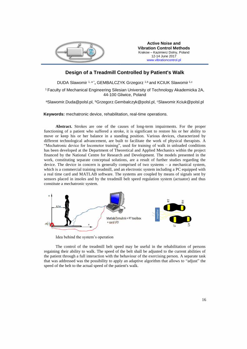
Idea behind the system’s operation
The control of the treadmill belt speed may be useful in the rehabilitation of persons
regaining their ability to walk. The speed of the belt shall be adjusted to the current abilities of
the patient through a full interaction with the behaviour of the exercising person. A separate task
that was addressed was the possibility to apply an adaptive algorithm that allows to “adjust” the
speed of the belt to the actual speed of the patient's walk.
Active Noise and Vibration Control Methods Krakow – Kazimierz Dolny, Poland
12-14 June 2017 www.vibrationcontrol.pl
17
Experimental investigations on energy harvesting from the mechanical vibrations of buildings
using Macro Fiber Composite
GRZYBEK Dariusz 1, a *, MICEK Piotr 2,b
1,* AGH University of Science and Technology, Faculty of Mechanical Engineering and Robotics, Krakow, Poland
2 AGH University of Science and Technology, Faculty of Mechanical Engineering and Robotics, Krakow, Poland
a [email protected], b [email protected]
Keywords: energy harvesting, piezoelectric composite, monitoring, vibrations
Abstract. A monitoring of the structure (e.g. building) enables a safety utilization of such
structure. The large number of sensors which measure selected parameters is often require in
applied monitoring system. Cables or batteries are used to power of such sensors. It lead to an
increase of utilization costs, because cables have to be spatial located in a monitored building
structure or batteries have to be changed in some time periods. An use of natural properties of
piezoelectric materials to a conversion of mechanical energy into an electric energy in places
where sensors are mounted is a promising field of wireless monitoring systems development. An
article presents the results of experimental study for the energy harvesting system using the
piezoelectric composite - P2-type Macro Fiber Composite (MFC). The device used for energy
harvesting had a beam structure which was achieved by gluing steel and MFC. The thickness,
length, and width of the base stainless steel beam were correspondingly the following 1.24 mm,
130 mm and 18 mm. The thickness, length, and width of the MFC were correspondingly the
following 0.3 mm, 85 mm and 14 mm. The subject of experimental research were the
determination of relationships between the values of vibrations amplitude and the amount of
generated energy. The increase of maximal value of vibration amplitude of the fixed end of
piezoelectric generator beam causes not only the nonlinear increase of maximal value of
vibration amplitude but also the expansion of the vibration frequency range in which generator
product the amount of electric power which is sufficient to the supply of wireless sensor. In the
laboratory experiments such amount of generated electric power was obtained for the vibration
amplitude of free end of generator beam which was bigger than 2 mm. On the basis of the
experimental research results the following main conclusions are established: the increase of
amplitude of the vibration of the fixed beam end causes the nonlinear increase of generated
electric power, the change of amplitude of the vibration of the fixed beam causes the change of
resonant frequency of piezoelectric beam generator. The maximum generated electric power is
obtained for this new resonant frequency, the increase of maximal value of the vibration
amplitude of the fixed end of piezoelectric generator beam causes the expansion of the vibration
frequency range in which the effective energy harvesting can be carried out.
Active Noise and Vibration Control Methods Krakow – Kazimierz Dolny, Poland
12-14 June 2017 www.vibrationcontrol.pl
18
Multibody simulation of hybrid controlled semi-active tracked suspension system
JURKIEWICZ Andrzej 1, a *, KOWAL Janusz 1, b and ZAJĄC Kamil 1, c
1 AGH University of Science and Technology, Faculty of Mechanical Engineering and Robotics, Al. A. Mickiewicza 30, 30-059 Krakow, Poland
a *[email protected], [email protected], [email protected]
Keywords: tracked platform, hybrid control, semi-active suspension, MSC Adams, MathWorks Matlab&Simulink, co-simulation.
Abstract. Described in this article simulation research are related to time domain analysis
of a tracked vehicle multibody model. The considered suspension system is based on real
construction of the 2S1 tracked vehicle suspension system. The multibody model has been
prepared in widely used MSC Adams environment. Due to research and development work, the
model has been enhanced with four magnetorheological dampers which have been placed in first
and last axles of the vehicle. Application of the damper caused the tested suspension system has
become a semi-active system. This kind of suspension provides the ability to generate variable
damping force and for this reason this system may be seen as a control system. During the
researches the hybrid control was considered as a proper way of vibration control. In case of
military vehicles or special purpose vehicles the ride comfort significantly affects the quality of
soldier’s work. The exposure of the human body to the vibrations could cause a muscular,
sensory, intellectual and emotional fatigue or even health problems. It follows that the ride
comfort is meaningful for the efficiency of operations on the battlefield. The choice of the hybrid
control stems from the fact that in the case of military vehicles in addition to the advantageous
conditions of work of vehicle crew also cornering stability and the possibility of sudden
acceleration or braking is also important. The hybrid control, which is combination of sky-hook
and ground-hook, allows to determine a compromise between ride comfort and stability of
tracked vehicle platform. The mentioned multibody model of the 2S1 tracked vehicle suspension
system consists inter alia of hull, rocker arms, track links, road, propulsion and idler wheels. Last
of these elements provides approximately constant tension of tracks while vehicle passes through
the obstacles. Track links are connected by so called rubber-bushings. Components which
introduce elastic potential energy are packages of spiral springs with logarithmic shape. It has
been noted, that the force generated by each package is non-proportional to its deflection. For
this reason, the nonlinear, identified equation of stiffness characteristic of package of spiral
springs with logarithmic shape has been applied in the multibody model. As mentioned before,
the multibody model consists four magnetorheological dampers also. Desired values of damping
forces are calculated by four independent programs. It means that adopted hybrid control forms
the control system wherein dampers are controlled independently. The control system has been
implemented in the MathWorks Matlab&Simulink environment. The co-simulation, using MSC
Adams environment also, has been developed to perform the time domain analysis. Passive and
semi-active systems have been compared due to ride comfort and stability of the 2S1 tracked
vehicle platform.
Active Noise and Vibration Control Methods Krakow – Kazimierz Dolny, Poland
12-14 June 2017 www.vibrationcontrol.pl
19
Influence of orthogonal methods on design process of active vibration control system for cantilever beam with non-collocated
piezo-elements
KOSZEWNIK Andrzeja , GOSIEWSKI Zdzisławb
Bialystok University of Technology , Faculty of Mechanical Engineering, Department on
Automatics and Robotics, Wiejska 45C, 15-351 Bialystok, Poland
a [email protected] , b [email protected]
Keywords: non-collocated beam, Schur decomposition, modal decomposition, piezo-element, root locus method
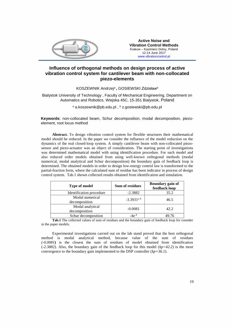
Abstract. To design vibration control system for flexible structures their mathematical
model should be reduced. In the paper we consider the influence of the model reduction on the
dynamics of the real closed-loop system. A simply cantilever beam with non-collocated piezo-
sensor and piezo-actuator was an object of consideration. The starting point of investigations
was determined mathematical model with using identification procedure. For such model and
also reduced order models obtained from using well-known orthogonal methods (modal
numerical, modal analytical and Schur decomposition) the boundary gain of feedback loop is
determined. The obtained models in order to design low-energy control law is transformed to the
partial-fraction form, where the calculated sum of residue has been indicator in process of design
control system. Tab.1 shown collected results obtained from identification and simulation.
Type of model Sum of residues Boundary gain of
feedback loop
Identification procedure -2.3882 35.2
Modal numerical
decomposition -3.3931e-4 46.5
Modal analytical
decomposition -0.0081 42.2
Schur decomposition -4e-4 49.76 Tab.1 The collected values of sum of residues and the boundary gain of feedback loop for consider
in the paper models.
Experimental investigations carried out on the lab stand proved that the best orthogonal
method is modal analytical method, because value of the sum of residues
(-0.0081) is the closest the sum of residues of model obtained from identification
(-2.3882). Also, the boundary gain of the feedback loop for this model (kp=42.2) is the most
convergence to the boundary gain implemented to the DSP controller (kp=36.1).
Active Noise and Vibration Control Methods Krakow – Kazimierz Dolny, Poland
12-14 June 2017 www.vibrationcontrol.pl
20
Human Sway on a Balance Platform
KOT Andrzej1, a *, NAWROCKA Agata1,b
1,* AGH University of Science and Technology
Faculty of Mechanical Engineering and Robotics
Department of Process Control
Mickiewicza Av. 30, Krakow, Poland
[email protected], [email protected]
Keywords: balance platform, vibration, low-frequency, dynamic properties.
Abstract. While many studies on the vibration effect influence on the human body noted
that in addition to the negative vibration impact at frequencies close to the human internal organs
natural frequency. This phenomenon has contributed to the development of the two main lines of
the research. In the first, the emphasis is set on the use of high frequency mechanical vibrations
in the training process. Vibrating platforms are used for this purpose. In the second case (i.e. the
balance platform which means controlled vibrating platform) low-frequency vibration (about
1Hz) is used, where appropriate vibration control allows you to maintain proper posture by
patient standing on the platform.
In the article mathematical model outline allowing for prediction of human behavior
during balancing at balance platform is presented. There are also presented results of tests for
human balancing at platform. Results were obtained by use of high speed camera for the various
set of the working conditions by means of the balance platform movement amplitude and
frequency.
Active Noise and Vibration Control Methods Krakow – Kazimierz Dolny, Poland
12-14 June 2017 www.vibrationcontrol.pl
21
Experimental Verification of Application of the Strain Measurement Method to Determination of Bending Moment
in Active Reduction of Transversal Vibrations of Beams by Piezoelectric Elements
KOZIEŃ Marek Stanisław1, a * and ŚCISŁO Łukasz2,b
1,* Cracow University of Technology, Faculty of Mechanical Engineering, Institute of Applied Mechanics, Al. Jana Pawła II 37, 31-864 Cracow, Poland
2Cracow University of Technology, Faculty of Electrical and Computer Engineering, Department of Automation and Information Technologies,
ul. Warszawska 24, 31-155 Cracow, Poland
[email protected], [email protected]
Keywords: beam, piezoelectric elements, strain gauge.
Abstract. Piezoelectric elements can be applied reduce of transversal vibrations of
beams. For reduction can be applied the passive method (dedicated for single frequency, or set of
frequencies) or the active one [2]. The authors proposed the original method for choosing the
value of control voltage based on identification of the bending moment in place of the
piezoelectric positions [1]. The method makes possible reduction of vibrations independently to
the shape form of the beam. The method was verified by numerical simulations for the case of
identification of the bending moment, when second derivative of the displacement in the control
point was approximately estimated based on the transversal displacement in three points by
application of the finite difference scheme [1]. The alternate attempt to experimental
determination of bending moment is measurement of the longitudinal strain on the external
surface of the beam [1]. It can be done e.g. by usage of strain gauge. The aim of analysis are
experimentally investigation of the influence of the position and base length of stain gauges in
comparison with dimension of the piezoelectric actuators on effectiveness of vibration reduction.
The measurements of work-in-progress type, are performed for the fixed-free beam. The beam is
kinematic-type excited by electrodynamic shaker. The generated signal makes possible to excite
different form of bending vibrations, especially the multimodal ones. Identification of the
bending moment is done under assumption of the linearity of the model, according to procedure
described in [2], as proportional to on-line measured signal coming from strain gauge(s) glued to
external surface of beam in place of mounting of piezoelectric elements. The active control
algorithm is driven by computer package LabVIEW.
Bibliography
[1] Kozień M.S., Ścisło Ł., Simulation of Control Algorithm for Active Reduction of
Transversal Vibrations of Beams by Piezoelectric Elements Based on Identification of Bending
Moment, Acta Physica Polonica A, vol. 128, no. 1A, A56-A61, 2015.
[2] Moheimani S.O.R., Fleming A.J., Piezoelectric Transducers for Vibration Control
and Damping. Springer Science & Business Media, 2006.
Active Noise and Vibration Control Methods Krakow – Kazimierz Dolny, Poland
12-14 June 2017 www.vibrationcontrol.pl
22
Identification of Rotor Parameters Using Piezoelectric Patches Bonded to the Shaft Surface
KOZIOŁ Mateusz 1, a * and CUPIAŁ Piotr 1,b
1,* AGH University of Science and Technology, Faculty of Mechanical Engineering and Robotics,
Al. A. Mickiewicza 30, 30-059 Kraków, Poland
[email protected], [email protected]
Keywords: rotor dynamics, smart structures, piezoelectricity, identification
Abstract. The work presents an attempt to identify parameters of a rotor system by using
piezoelectric elements bonded to the surface of the shaft. The structure being tested is similar to
the Jeffcott rotor, and it consists of a rotating beam with a disc placed in its middle. Besides the
basic quantities like unbalance, more complicated parameters are also considered. The authors
assess the magnitude of the shaft bow, angular position of the unbalance- and the bow plane (in
reference to a marker on the shaft), as well as the stiffness of the supports and the damping
parameters. The aim of these studies is to obtain the parameters used in the numerical analysis of
the smart rotor models, previously developed by the authors. This will allow, in the next step, for
an experimental verification of the simulation models, as well as the laboratory confirmation of
typical phenomena appearing in rotating systems, predicted by such models. Typically,
identification process, e.g., of unbalance, uses vibration data acquired from accelerometers. In
the present approach, the signals are received from piezoelectric sensors placed on the shaft
surface. It means that these signals are related to the rotating coordinate frame, and therefore
they must be treated differently. For example, the shaft deflection due to the unbalance measured
at the critical rotational speed is constant in a rotating frame, whereas it undergoes synchronous
vibration in the stationary frame. Special effort must therefore be taken in planning the tests, to
account for the reference frame being used. The justification for using piezoelectric patch
sensors is that the same elements will be applied together with piezoelectric patch actuators in
the active control of a smart rotor. The possibilities of several control algorithms to influence the
effective damping of a smart rotor have been studied numerically in the authors’ previous
papers.
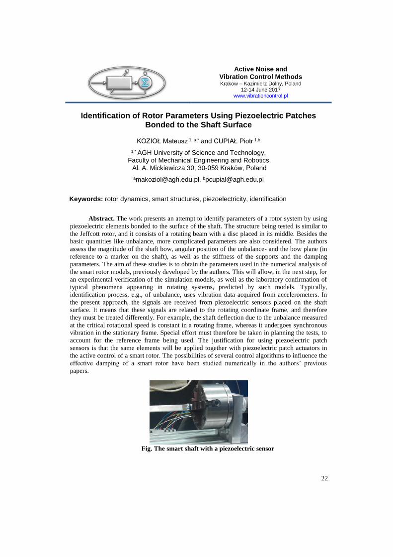
Fig. The smart shaft with a piezoelectric sensor
Active Noise and Vibration Control Methods Krakow – Kazimierz Dolny, Poland
12-14 June 2017 www.vibrationcontrol.pl
23
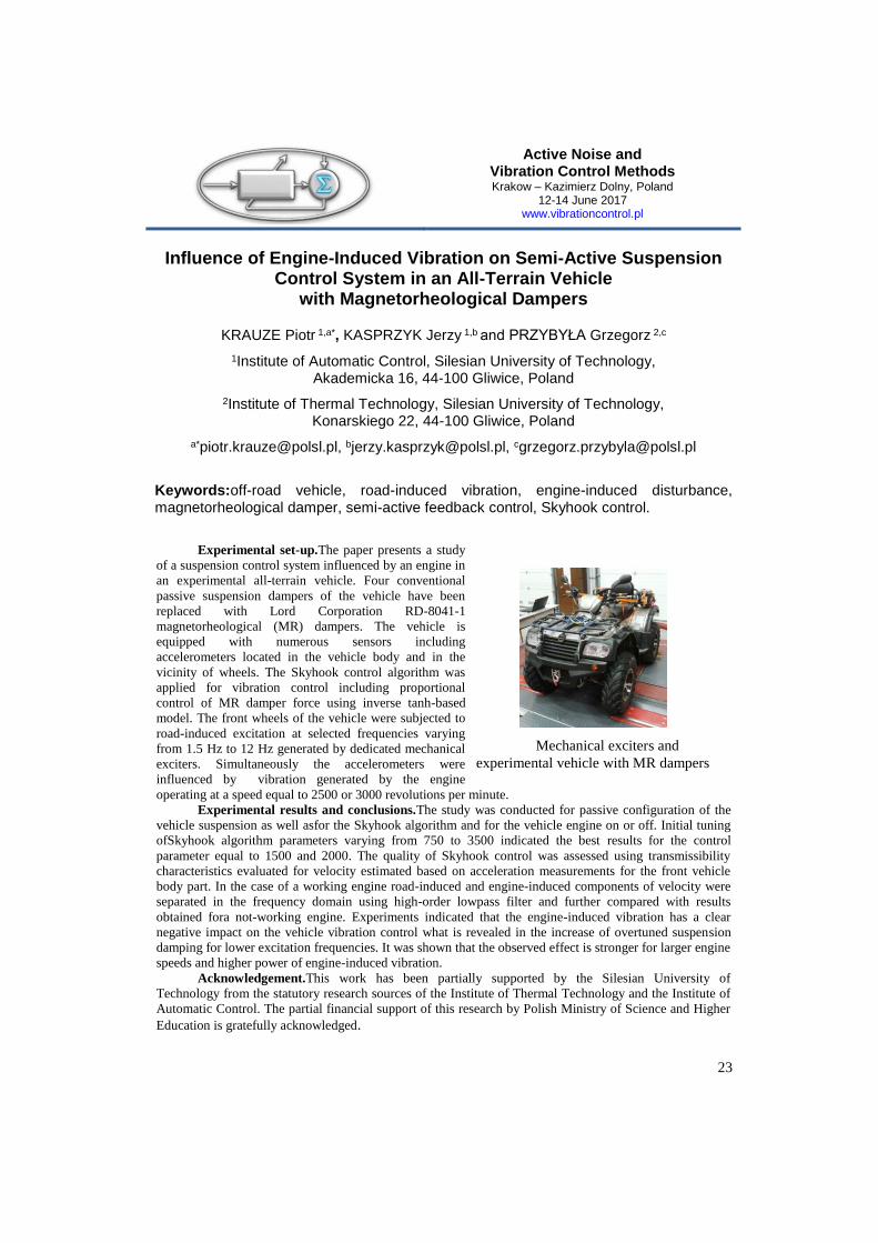
Mechanical exciters and
experimental vehicle with MR dampers
Influence of Engine-Induced Vibration on Semi-Active Suspension Control System in an All-Terrain Vehicle
with Magnetorheological Dampers
KRAUZE Piotr 1,a*, KASPRZYK Jerzy 1,b and PRZYBYŁA Grzegorz 2,c
1Institute of Automatic Control, Silesian University of Technology, Akademicka 16, 44-100 Gliwice, Poland
2Institute of Thermal Technology, Silesian University of Technology, Konarskiego 22, 44-100 Gliwice, Poland
a*[email protected], [email protected], [email protected]
Keywords:off-road vehicle, road-induced vibration, engine-induced disturbance, magnetorheological damper, semi-active feedback control, Skyhook control.
Experimental set-up.The paper presents a study
of a suspension control system influenced by an engine in
an experimental all-terrain vehicle. Four conventional
passive suspension dampers of the vehicle have been
replaced with Lord Corporation RD-8041-1
magnetorheological (MR) dampers. The vehicle is
equipped with numerous sensors including
accelerometers located in the vehicle body and in the
vicinity of wheels. The Skyhook control algorithm was
applied for vibration control including proportional
control of MR damper force using inverse tanh-based
model. The front wheels of the vehicle were subjected to
road-induced excitation at selected frequencies varying
from 1.5 Hz to 12 Hz generated by dedicated mechanical
exciters. Simultaneously the accelerometers were
influenced by vibration generated by the engine
operating at a speed equal to 2500 or 3000 revolutions per minute.
Experimental results and conclusions.The study was conducted for passive configuration of the
vehicle suspension as well asfor the Skyhook algorithm and for the vehicle engine on or off. Initial tuning
ofSkyhook algorithm parameters varying from 750 to 3500 indicated the best results for the control
parameter equal to 1500 and 2000. The quality of Skyhook control was assessed using transmissibility
characteristics evaluated for velocity estimated based on acceleration measurements for the front vehicle
body part. In the case of a working engine road-induced and engine-induced components of velocity were
separated in the frequency domain using high-order lowpass filter and further compared with results
obtained fora not-working engine. Experiments indicated that the engine-induced vibration has a clear
negative impact on the vehicle vibration control what is revealed in the increase of overtuned suspension
damping for lower excitation frequencies. It was shown that the observed effect is stronger for larger engine
speeds and higher power of engine-induced vibration.
Acknowledgement.This work has been partially supported by the Silesian University of
Technology from the statutory research sources of the Institute of Thermal Technology and the Institute of
Automatic Control. The partial financial support of this research by Polish Ministry of Science and Higher
Education is gratefully acknowledged.
Active Noise and Vibration Control Methods Krakow – Kazimierz Dolny, Poland
12-14 June 2017 www.vibrationcontrol.pl
24
Active Structural Acoustic Control with Real Device and MFC sensors
KURCZYK Sebastian1, a *, MAZUR Krzysztof1, b, WRONA Stanislaw1, c and PAWELCZYK Marek1, d
1, Institute of Automatic Control, Silesian University of Technology, Gliwice, Poland
a*[email protected], [email protected], [email protected], [email protected]
Keywords: real device; active casing; active noise control; MFC.
Abstract. Exposure to excessive noise can be frustrating and harmful to the health or
human life. People are exposed to noise not only in the industrial environment but also in their
households. As a result, there is a need for noise reduction systems in household appliances.
Noise can be reduced with passive or active methods. In some cases, passive solutions lead to
unacceptable modifications to the equipment e.g.: increase of thermal insulation, exceed of the
permissible dimensions of the enclosure. An alternative is the use of active methods which are
particularly effective for low-frequency noise. For the construction of an active noise reduction
system vibration of the enclosure can be used. In the literature there are known solutions based
on the vibration control of the housing, to reduce the transmission of noise through the casing
wall. In this paper a real active structural acoustic control system is discussed. The system
utilizes piezoelectric sensors to collect data. Experimental data from a commercially available
washing machine are analysed and discussed.
Discussion. Three piezoceramic sensors were considered to be used for reference signal:
polyvinylidane difluoride (PVDF) and two types (namely P1, P2) of macro fibre composite
(MFC). Active device casing utilizes electrodynamic exciters mounted on each wall to produce
control signal. Error microphones located in front of each wall are used for the control purpose
and another five evaluation microphones are used for the system performance assessment.
Scope of the paper. This paper focuses on multi-channel feedforward active noise
control (ANC) system for a real machine, namely a market available washing machine. The use
of piezoelectric sensor as a reference source is considered.
Conclusions. The use of MFC in place of regular microphone allows smaller sensor to be
used in ANC system, thus reducing its mechanical size and complexity. However, MFC
placement must be carefully analysed in order to provide satisfactory sensor magnitude
characteristic.
The results obtained during the experiment indicates that MFC can be successfully used
in place of a regular microphone. The system performed a stable, global noise reduction. The
results were similar (2~dB worse) to those obtained with a reference microphone.
Active Noise and Vibration Control Methods Krakow – Kazimierz Dolny, Poland
12-14 June 2017 www.vibrationcontrol.pl
25
Clipped stiffness force with viscous damping in semi-active tuned mass dampers for reduction of harmonic vibrations
MAŚLANKA Marcin
AGH University of Science and Technology, Department of Process Control al. A. Mickiewicza 30, 30-059 Krakow, Poland
e-mail: [email protected]
Keywords: vibration, damping, semi-active, feedback, control, tuned mass damper, MR damper.
Abstract. Tuned mass dampers (TMDs) are common passive devices that are widely used
in vibration control of structures. Although many vibration problems are solved in a simple way
with traditional TMDs, there are well recognized limitations of TMDs which triggered the
development of controlled mass dampers. The variety of active tuned mass dampers (ATMDs)
and semi-active tuned mass dampers (STMDs) are reported to have significantly better
performance than TMDs. ATMDs use active actuators, like hydraulic cylinders, to both add and
dissipate energy from the structure. STMDs use controllable dampers that can only dissipate
energy thus the need for external power is significantly smaller when compared to ATMDs. In
recent years, STMDs with magnetorheological (MR) dampers are developed which consist of a
mass, a spring and a real-time controlled MR damper. This paper proposes a new control
algorithm for MR dampers in STMDs subjected to harmonic excitation. The proposed control
algorithm for MR dampers in STMDs is based on internal feedbacks from relative displacement
and relative velocity of STMD, and targets to achieve damping performance of STMD similar to
that of the TMD with three times larger mass. The paper first formulates an unclipped (active)
control force which is the combination of a frequency dependent negative or positive stiffness
force and a viscous damping force calibrated such that the unclipped control force is equivalent
to the well-known optimal acceleration feedback control. Then, a sub-optimal control approach
is introduced with clipped (semi-active) stiffness force with viscous damping. It is shown that
after clipping of active forces, which is required for semi-active realization of the control
approach, the resulting clipped control force significantly differs from its optimal active
counterpart. Analytical expressions for the equivalent positive or negative stiffness and the
equivalent damping resulting from the clipped stiffness force with viscous damping are derived
and used to explain the effect of clipping on the performance of STMD. Finally, the correction
factors are introduced to compensate, to some extend, for the effect of clipping. The
effectiveness of the proposed control approach for STMDs is numerically demonstrated with
comparison to the traditional TMD.
Active Noise and Vibration Control Methods Krakow – Kazimierz Dolny, Poland
12-14 June 2017 www.vibrationcontrol.pl
26
Feed-forward active noise control for a washing machine casing
MAZUR Krzysztof1, a *, WRONA Stanislaw1,b, PAWELCZYK Marek1,c
1 Institute of Automatic Control,
Silesian University of Technology, Akademicka 16, 44-100 Gliwice, Poland
[email protected], [email protected], [email protected]
Keywords: active noise control, adaptive control, active casing
Abstract. Noise generated by devices is a common problem in both industrial and home
environments. In some cases reduction of such noise is a difficult task. One of such cases is a
reduction of the low frequency noise. This kind of noise is very common in rotating machines
with low rotational speeds. For low frequency noise passive noise reduction methods have
limited performance due to low barrier width compared to the wavelength of sound. The actively
controlled thin barrier may provide better results. The performance of such active method has
been confirmed by the authors using a dedicated noise-canceling casing. In this paper the same
method is applied to an off-the-shelf washing machine. An adaptive FXLMS algorithm is
proposed for the active control of the casing to provide noise reduction. Commonly used feed-
forward structure is used, with a reference microphone located inside the washing machine. The
performance of the resulting control system is experimentally verified using a loudspeaker
placed inside the washing machine to provide reproducible noise, and obtained results are
reported.
Conclusions. The operation of active noise reduction system has been experimentally
verified on an unmodified, except for adding actuators, off-the-shelf waching machine. The
proposed feed-forward active control solution provides good global noise reduction, more than 7
dB on average at monitoring microphones located around the room, for the reproduced spinning
noise. This noise reduction is about 3 dB higher than in case of feedback approach, mostly due to
presence of non-tonal, hard to predict, components in the noise spectrum.
For pure tonal or multitone disturbances, where the signal can be easily predicted, a very
high noise reduction levels can be obtained, reaching more than 10 dB globally in the entire
room space.
Acknowledgements. The research reported in this paper has been supported by the
National Science Centre, decision no. DEC-2012/07/B/ST7/01408, and by the Ministry of
Science and Higher Education, Poland.
Active Noise and Vibration Control Methods Krakow – Kazimierz Dolny, Poland
12-14 June 2017 www.vibrationcontrol.pl
27
Operational Modal Analysis of the large structure workpieces
MAZUR Michał 1, a *, KALIŃSKI Krzysztof J. 2,b
1*,2 Gdańsk University of Technology, Poland
[email protected],[email protected]
Keywords: OMA, harmonics, finite element method
Abstract. The paper presents the application of the Operation Modal Analysis
identification techniques in the presence of harmonic excitations of the large structures’
workpieces. The main problem of Experimental Modal Analysis in the case of large workpieces
is an elastic fixture, which could not be neglected. Moreover the mass of the workpiece is huge
and damping through the complicated fixture could be significant too. Thus to obtain good
quality of measurement data the large excitations forces are required. By using big enough
modal hammers workpiece could be easily damaged and using modal exciters is not always
feasible or economically justified. Thus OMA technique may be applied here, but the presence
of the harmonic excitation during the manufacturing could be serious problem. The assumption
of the white noise excitation is not met in this case. There are techniques for identifying and
filtering modal harmonics (i.e. basing at the Empirical Mode Decomposition), but by applying
filters we are risking of loosing important data from measurement signals. The other approach is
to use modified techniques for modal parameters identifications which includes harmonic
functions. Such techniques could have serious advantages over the filtering and classical OMA:
ability of detecting weaker excited modes and detecting modes that are close to the harmonics.
Generally ability to observe real structure responses during the process of the manufacturing
could be considered as the main advantage of the Operational Deflection Shapes and OMA
techniques. However if we want to use such obtained data for the correlation with the Finite
Element Method model, there is a need to observe as much modes as it is possible. Moreover,
we are planning usage of further such obtained data for simulating the manufacturing process to
tune its parameters (like e.g. spindle speed). Modes neglected in one set of the manufacturing
parameters may become serious problem with another set of the manufacturing parameters. We
are discussing the result of the identifications performed by selected OMA techniques with and
without harmonic excitations, EMA results and FEM data.
Active Noise and Vibration Control Methods Krakow – Kazimierz Dolny, Poland
12-14 June 2017 www.vibrationcontrol.pl
28
Continuous measurement of filling in a two-tank liquid level control system
OLEJNIK Paweł 1,a* and AWREJCEWICZ Jan 1,b
1,* Lodz University of Technology, Department of Automation, Biomechanics and Mechatronics, 1/15 Stefanowski Str., 90-924 Lodz, Poland
[email protected], [email protected]
Keywords: hydraulic systems, closed-loop control, data acquisition, embedded systems, programmable controller, mathematical modelling.
Abstract. In this work, a few mechatronic devices like a switch designated for continuous
measurements, the solenoid valve, a peristaltic pump and an universal programmable controller
are consolidated in a precise liquid level closed-loop control system. The digital programmable
controller embedded in the integrated system NI cRIO-9074 combines a real-time processor and
a re-configurable field-programmable gate array. Realization of various control tasks is preceded
by identification of system parameters. Then, a sequential closed-loop control system based on a
P/PD-correction is applied to: 1) maintain the desired set-point level at leakages – system
disturbances; 2) follow a prescribed series of time-varying reference levels. Mathematical
models of the two configurations of the investigated hydraulic control system are implemented
using LabVIEW virtual instruments. As a result, there are provided approximate characteristics
of identified system parameters as well as time histories of process variable converging to
reference set-points or following a path.
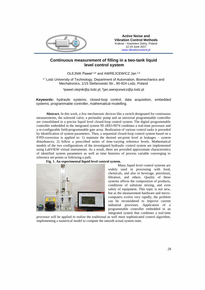
Fig. 1. An experimental liquid level control system.
Many liquid level control systems are
widely used in processing with food,
chemicals, and also in beverage, petroleum,
filtration, and others. Quality of these
systems affects the composition of products,
conditions of substrate mixing, and even
safety of equipment. This topic is not new,
but as the measurement hardware and micro-
computers evolve very rapidly, the problem
can be reconsidered to improve current
industrial processes. Application of a
programmable controller embedded in an
integrated system that combines a real-time
processor will be applied to realize the traditional as well more sophisticated control algorithm,
implementing a numerical model to compute the smooth actual system state.

Active Noise and Vibration Control Methods Krakow – Kazimierz Dolny, Poland
12-14 June 2017 www.vibrationcontrol.pl
29
Influence of sliding mode control parameters on the efficiency of a car suspension system for the reduction of vibration
ORKISZ Paweł b, SNAMINA Jacek a
Department of Process Control, AGH University of Science and Technology,
30-059, Cracow, Mickiewicza 30
[email protected], [email protected]
Keywords: vibration reduction system, sliding mode control, active damping.
Abstract. With the development of the automotive industry, the engineers are creating more
and more perfect car suspensions. Active and semiactive elements are introduced with
appropriate control systems in place of traditional passive suspensions. The efficiency of the
modern vibration reduction systems is mainly dependent on the control algorithms and the
technical possibilities of their implementation. This paper presents the concept of introducing a vibration reduction system based on the
sliding control algorithm to Isuzu D-Max original suspension. In the calculations and in the
design of the laboratory stand a simple
model called the "quarter of the car" was
used. Taking into account the construction
presented schematically in Fig.1a, the
parameters of the model shown in Fig.1b
were determined. Using the principles of
dynamical similarity, a "quarter of the car"
laboratory model with active vibration
reduction system was built. A linear motor
was used as the actuator in active vibration
reduction system.
Practical use of the sliding control
algorithm requires estimation of the value of
its basic parameters. The first parameter
limits the maximum value of force disturbing the static equilibrium position of the
vibro-insulated subsystem. The second defines the inclination of the sliding surface in the state
space. The third determines the speed of reaching the sliding surface from any point of the state
space. A number of measurements were performed on the laboratory stand for various parameters
of the proposed algorithm. As a result, the best possible values were determined taking into
account the technical limitations of the laboratory model and the suspension of the Isuzu D-Max
car. In the simulations, the algorithm for generating road unevenness profiles was used according
to the classification given in the ISO 8608 standard.
This work was supported by National Centre for Research and Development of Poland (research
project No. PBS3/B6/27/2015).
F
B
A
C
D
E
z
x1
x2
m1
m2
b1
b2
k1
k2 S
Fig. 1
x1
x2
a) b)
z
Active Noise and Vibration Control Methods Krakow – Kazimierz Dolny, Poland
12-14 June 2017 www.vibrationcontrol.pl
30
Analytical model of the vibrations of the BLDC motor with mechanical faults
RADKOWSKI Stanisław 1 and SZULIM Przemysław 1*
1 Warsaw University of Technology, Faculty of Automotive, Narbutta 84, Waszawa
Keywords: vibration, BLDC motor modeling, diagnosis, fault analysis.
Abstract: In the paper Authors present a model connecting influence of typical mechanical
faults, like eccentricity, torque pulsation and demagnetization on vibrations spectrum of
brushless DC (BLDC) motor. Accurate process of modeling was presented. A 2D model of
motor was taking in consideration. Each of a characteristic section (i.e. rotor shaft, rotor core,
permanent magnet, air gap, stator core, and exterior region) was described by partial differential
equations. Each equation, together with boundary conditions, creates set of ten partial
differential equations describing distribution of magnetic potential and magnetic field. At this
stage chosen faults were modeled. Analytical model of unbalanced force and cogging torque as a
source of vibrations were calculated. In order to simulate behavior of working model of motor
Matlab software was used, where the model of electric commutator and the developed magnetic
model were joined together. Results were compared with real vibration signal acquired from the
test stand with BLDC motor.
Active Noise and Vibration Control Methods Krakow – Kazimierz Dolny, Poland
12-14 June 2017 www.vibrationcontrol.pl
31
Simulation nonlinear backstepping method in active suspension control of the four-wheeled mobile platform
RADKOWSKI Stanisław 1, a *, SEŃKO Jarosław 1,b and SŁOMCZYŃSKI Maciej 1,c
1 Narbutta 84, 02-524 Warsaw,Poland
a [email protected], b,* [email protected], c
Keywords: active suspension, backstepping controller, four-wheeled mobile platform.
Abstract. The paper presents design a semiactive controller for a vehicle suspension
system. The controller was developed for the laboratory model Semi Active Suspention System
which represents a quarter of four-wheeled mobile platform model.
Initially Semi Active Suspention system was modeled by the mathematical equations and
then the backstepping controller was designed to suppress the vibrations of the car body.
Backstepping is a design methodology of control laws for nonlinear systems. Backstepping is a
novel nonlinear control technique based on the Lyapunov function design approach, used when
higher derivatives of parameter estimation appear. The paper presents a new method of
performing integrator backstepping in systems that are discontinuous, either due to their inherent
structure or because of the applied control input A proposed nonlinear backstepping design
scheme, which is developed for the control of suspension systems to improve the ride quality
and suspension travel, is proposed in this paper. Since ride quality is dependent on a vertical
displacements of a vehicle body, the design of active suspensions must have the potential to
minimize heave and pitch movements in order to guarantee the ride comfort of passengers. The
other important factor to be emphasized in the design is the suspension travel which means the
space variation between the car body and the tires. In order to avoid damaging vehicle
components the active suspension controllers must be capable of preventing the suspension from
hitting its travel limits.
Our model presents a quarter of the car's suspension with a nonlinear spring or a linear
spring, and a silencer with magnetorheological fluid, by which the damping of the suspension is
being modified. The Simulation model of the Semi Active Suspention were designed and solved
in Matlab and ADAMS.
Active Noise and Vibration Control Methods Krakow – Kazimierz Dolny, Poland
12-14 June 2017 www.vibrationcontrol.pl
32
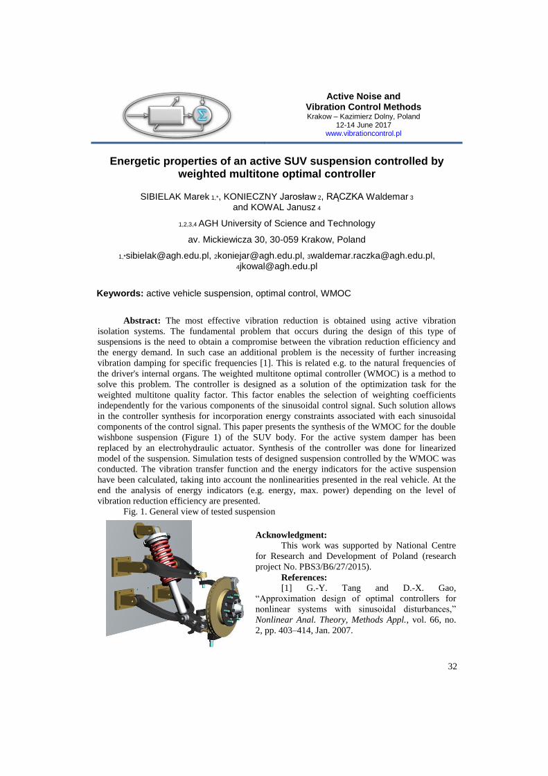
Energetic properties of an active SUV suspension controlled by weighted multitone optimal controller
SIBIELAK Marek 1,*, KONIECZNY Jarosław 2, RĄCZKA Waldemar 3
and KOWAL Janusz 4
1,2,3,4 AGH University of Science and Technology
av. Mickiewicza 30, 30-059 Krakow, Poland
1,*[email protected], [email protected], [email protected], [email protected]
Keywords: active vehicle suspension, optimal control, WMOC
Abstract: The most effective vibration reduction is obtained using active vibration
isolation systems. The fundamental problem that occurs during the design of this type of
suspensions is the need to obtain a compromise between the vibration reduction efficiency and
the energy demand. In such case an additional problem is the necessity of further increasing
vibration damping for specific frequencies [1]. This is related e.g. to the natural frequencies of
the driver's internal organs. The weighted multitone optimal controller (WMOC) is a method to
solve this problem. The controller is designed as a solution of the optimization task for the
weighted multitone quality factor. This factor enables the selection of weighting coefficients
independently for the various components of the sinusoidal control signal. Such solution allows
in the controller synthesis for incorporation energy constraints associated with each sinusoidal
components of the control signal. This paper presents the synthesis of the WMOC for the double
wishbone suspension (Figure 1) of the SUV body. For the active system damper has been
replaced by an electrohydraulic actuator. Synthesis of the controller was done for linearized
model of the suspension. Simulation tests of designed suspension controlled by the WMOC was
conducted. The vibration transfer function and the energy indicators for the active suspension
have been calculated, taking into account the nonlinearities presented in the real vehicle. At the
end the analysis of energy indicators (e.g. energy, max. power) depending on the level of
vibration reduction efficiency are presented.
Fig. 1. General view of tested suspension
Acknowledgment:
This work was supported by National Centre
for Research and Development of Poland (research
project No. PBS3/B6/27/2015).
References: [1] G.-Y. Tang and D.-X. Gao,
“Approximation design of optimal controllers for
nonlinear systems with sinusoidal disturbances,”
Nonlinear Anal. Theory, Methods Appl., vol. 66, no.
2, pp. 403–414, Jan. 2007.
Active Noise and Vibration Control Methods Krakow – Kazimierz Dolny, Poland
12-14 June 2017 www.vibrationcontrol.pl
33
Influence of the damper characteristic shaping on the vehicle suspension properties
SIBIELAK Marek1, a, KONIECZNY Jarosław2, b, SMOTER Adam3, c*
1, 2, 3* AGH University of Science and Technology
Al. Mickiewicza 30, 30-059 Kraków, Poland
[email protected], [email protected], [email protected]
Keywords: suspension, wheeled vehicle, nonlinear model, characteristic shaping, identification
Abstract. The paper focuses on the parametric identification of the nonlinear suspension
model of a wheeled vehicle. It is based on the laboratory tests of the passive, commercial quarter
car suspension of a SUV vehicle. The linear spring characteristic and nonlinear damper
characteristic were determined separately from the suspension system. The damper characteristic
was obtained by using isokinetic excitation. Such an approach allowed to determine the static
damper characteristic by averaging the appropriate intervals of recorded signals. The obtained
nonlinear characteristic of the damper was approximated by a piecewise linear function. The
suspension model is a 2DOF model with the piecewise linear shock absorber characteristic. The
paper presents the influence of static characteristic shaping of the damper on dynamic
characteristics of the suspension system. The displacement based transmissibility function, tire
deflection function and rattle space function were taken into consideration. Nine cases of the
modified damper characteristic were considered. For each case the comfort oriented and the
road-holding oriented performance index were computed. Changing the shape of the
characteristic consists in changing the slope coefficient of straight-line sections of the piecewise
linear function. The paper was justified the need to modify the characteristics of the damper in
such a way that it passes through the origin of the Cartesian coordinate system. It has been
assumed that the shock absorber can be represented as a parallel linear spring and nonlinear
damping element. The isokinetic excitation and proposed averaging procedure enable to obtain a
stiffness coefficient of a spring in order to eliminate its effect on the shock absorber
characteristic.
Acknowledgments. This paper was supported by National Centre for Research and Development
of Poland (research project No. PBS3/B6/27/2015). This paper was partially funded by a Dean's
grant from the Faculty of Mechanical Engineering and Robotics AGH University of Science and
Technology.
Active Noise and Vibration Control Methods Krakow – Kazimierz Dolny, Poland
12-14 June 2017 www.vibrationcontrol.pl
34
Optimal placement of actuators for active control of a washing machine casing
WRONA Stanislaw a*, MAZUR Krzysztof, PAWELCZYK Marek, and KLAMKA Jerzy
Institute of Automatic Control, Silesian University of Technology, Gliwice, Poland
Keywords: active casing; active noise control; optimization; inertial actuators; real device casing.
Abstract. An excessive noise generated by industrial devices or home appliances can
represent a significant threat to human health. In a working environment, high-level noise or
prolonged exposure can lead to hearing loss. On the other hand, household appliances can also
generate excessive noise, inducing stress, annoyance, and significantly obstructing work or
leisure. A common protection solution is to apply passive sound-insulating materials. However,
passive barriers are often ineffective, especially at low frequencies, or are inapplicable due to
increase in size and weight of the device, and its potential overheating. An alternative approach
is to use active control methods by applying a set of sensors and actuators, and running a control
algorithm. If the device generating excessive noise is surrounded by a thin-walled casing (or if it
can be enclosed in an additional casing), then control inputs can be applied directly to the
structure. Thus, the structure vibrates in a relevant manner, and as a whole it can be used as an
active barrier enhancing acoustic isolation of the device. When appropriately implemented, it
results in a global noise reduction instead of only local zones of quiet. Such approach is called
the active casing approach, and it was further developed by the authors and successfully applied
in previous research. Initially, a rigid casing has been examined, which limits the couplings
between walls mainly to the acoustic field. Then, a light-weight casing has been considered,
characterized by strong additional vibrational couplings. In this paper, as a natural continuation
towards commercial application, a real device casing is considered, namely, a market-available
and unmodified product – a washing machine. In the previous research it was observed that for
an effective active control it is important to mount sensors and actuators at appropriate locations
on the vibrating structure. The method developed previously for laboratory casings is now
applied and verified for a real device casing. An important complication with respect to the
previous research is that the real device casing is very irregular and inhomogeneous. Each of the
casing walls represent different features, i.e. bendings, embossments, etc., what makes the task
of mathematical modelling significantly more difficult. The vibration of an unloaded casing is
measured with a laser vibrometer and analysed. A mathematical model is adapted to the purpose
of actuator positioning on the casing. The optimization criterion used in this paper is based on a
measure of the controllability Gramian matrix.
Acknowledgement. The research reported in this paper has been supported by the
National Science Centre, Poland, decision no. DEC-2014/13/B/ST7/00755, and the Ministry for
Higher Education and Science.
Active Noise and Vibration Control Methods Krakow – Kazimierz Dolny, Poland
12-14 June 2017 www.vibrationcontrol.pl
35
Electroacoustic methods for detecting of deformed speech parameters.
WSZOŁEK Wiesław 1, a *, MALCZYK Grażyna 2,b
1,* AGH University of Science and Technology, Krakow, Poland
2Medical University of Gdańsk. Department of Neurology, Gdańsk, Poland
[email protected], [email protected]
Keywords: vocal fold vibration speech signal, fundamental frequency.
Abstract. The emitted speech signal is a source of useful diagnostic and prognostic
information. Besides of the individual features of a speaker, the speech signal carries semantic
and emotional state information, and other kinds, enabling to determine speaker’s social status,
education, and overall health, for example stuttering. In this work particular attention is paid to
the defect of pronunciation of people stuttering. Stuttering is a disorder of fluency. This disorder
is caused by, among other things spasticity respiratory muscle movement, phonation and
articulation and the lack of proper coordination, or incoordination of the entire respiratory and
articulatory, producing, among others, muscle spasms of the larynx, leading to blocking,
jamming, repetition, prolonging phonation: individual sounds, syllables, words and whole
phrases. They are classified as clonic stuttering, or the repetition of these sounds, syllables,
words or phrases, or as a tonic blocking, which is the inability to notice the sound, desire, and at
the same time the impossibility of extraction speak. It is a aphonia lasting several or even several
seconds, lasts as long as the patient is struggling with muscle tensions. The study included 8
people who stutter: 3 women and 5 men aged 12 to 50 years, including a boy aged 12, a girl
under 14 years and other adults who themselves came to the therapy due to the lack of freedom
of speech and big problems with communication. Registration time acoustic signal waveform of
speech (the text read) and EGG1 signal was performed in an anechoic chamber Department of
Mechanics and Vibroacoustics, AGH University of Science and Technology. One of the
methods of testing which gives opportunities for a proper evaluation of the vocal folds in the
process of stuttering, and the diagnosis of these disorders and for monitoring the progress of
both, as well as the final effects of stuttering therapy is electroglottographic methods and
acoustic spectral analysis of speech. In this paper we present the results of the speech signal
stutterers. On the basis of these results, we developed a method of identifying types of stuttering.
1 EGG – Electroglottography - Is a non-invasive method of measuring the vibration of the vocal folds,
which consists in measuring the electrical impedance between two electrodes placed on the neck of the test
subject, at the level of the larynx
Active Noise and Vibration Control Methods Krakow – Kazimierz Dolny, Poland
12-14 June 2017 www.vibrationcontrol.pl
36
Sliding mode and LQR approach to control of active vehicle suspension
ZAWARTKA Magdalena 1, a *, KONIECZNY Jarosław2,b ,SIBIELAK Marek3,c ,RĄCZKA Waldemar4,d
1*,2,3,4 AGH University of Science and Technology al. A. Mickiewicza 30, 30-059 Kraków, Poland
a [email protected], b [email protected], c [email protected], [email protected]
Keywords: sliding mode control, active suspension, model reference control, LQR
Abstract. The purpose of an investigation a vibration reduction system controlled by
different algorithms is to find out their efficiency in extenuation of vibrations. In this paper three
different approaches are introduced: model reference sliding mode control (MRSMC) with sky-
hook reference model, MRSMC with ground-hook reference model and linear-quadratic
regulator (LQR). Each algorithm was tested in three criteria: displacement transmissibility
function criterion, tire deflection criterion and external energy consumption criterion.
Suspension analysis for the adopted indicators was performed for selected damping values
𝑐𝑠𝑘𝑦 , 𝑐𝑔𝑟𝑜𝑢𝑛𝑑. The influence of changes in suspension parameters on the used evaluation criteria
for all the regulators considered was compared. Realization of sliding mode control (SMC) with
a reference model allow to perform frequency characteristics of sky-hook or ground-hook by the
object which is vehicle suspension. What is more proposed control law resolve the value of the
force generated by the absorber in such a way that the object follows the state trajectory of the
reference model. Third method is adopting a LQR. The regulator was designated for a linearized
model and the tests were performed for a nonlinear model. The proposed quality indicator takes
into account both improved safety (road-holding) and comfort (displacement transmissibility
function). It also allows you to limit the power of the control signal. In addition all parameters of
quarter car vehicle suspension model used in laboratory tests are taken from real SUV Isuzu D-
MAX.
Acknowledgments. This paper was supported by National Centre for Research and
Development of Poland (research project No. PBS3/B6/27/2015). This paper was partially
funded by a Dean's grant from the Faculty of Mechanical Engineering and Robotics AGH
University of Science and Technology.

37

38
NOTICE
..............................................................................................................................................
..............................................................................................................................................
..............................................................................................................................................
..............................................................................................................................................
..............................................................................................................................................
..............................................................................................................................................
..............................................................................................................................................
..............................................................................................................................................
..............................................................................................................................................
..............................................................................................................................................
..............................................................................................................................................
..............................................................................................................................................
..............................................................................................................................................
..............................................................................................................................................
..............................................................................................................................................
..............................................................................................................................................
..............................................................................................................................................
..............................................................................................................................................
..............................................................................................................................................
..............................................................................................................................................
..............................................................................................................................................
39
AUTHORS’ INDEX
A
AWREJCEWICZ Jan ______________________ 28
B
BĄKOWSKI Andrzej _____________________ 13 BIENIOSZEK Grzegorz ___________________ 14
C
CUPIAŁ Piotr __________________________ 22
D
DANEK Wojciech _______________________ 14 DEKÝŠ Vladimir ________________________ 13 DOMINIK Ireneusz ______________________ 15 DUDA Slawomir ________________________ 16
G
GEMBALCZYK Grzegorz __________________ 16 GOSIEWSKI Zdzisław ____________________ 19 GRZYBEK Dariusz _______________________ 17
J
JURKIEWICZ Andrzej ____________________ 18
K
KALIŃSKI Krzysztof J. ____________________ 27 KASPRZYK Jerzy ________________________ 23 KCIUK Slawomir ________________________ 16 KCIUK Sławomir ________________________ 14 KLAMKA Jerzy _________________________ 34 KONIECZNY Jarosław ______________ 32, 33, 36 KORZENIOWSKI Waldemar _______________ 15
KOSZEWNIK Andrzej ____________________ 19 KOT Andrzej ___________________________ 20 KOWAL Janusz ______________________ 18, 32 KOZIEŃ Marek Stanisław _________________ 21 KOZIOŁ Mateusz _______________________ 22 KRAUZE Piotr __________________________ 23 KURCZYK Sebastian _____________________ 24
L
LALIK Krzysztof ________________________ 15
M
MALCFZYK Grażyna _____________________ 35 MAŚLANKA Marcin _____________________ 25 MAZUR Krzysztof _________________ 24, 26, 34 MAZUR Michał _________________________ 27 MICEK Piotr ___________________________ 17
N
NAWROCKA Agata ______________________ 20
O
OLEJNIK Paweł _________________________ 28 ORKISZ Paweł__________________________ 29
P
PAWELCZYK Marek _______________ 24, 26, 34 PRZYBYŁA Grzegorz _____________________ 23
R
RADKOWSKI Stanisław _______________ 30, 31 RADZISZEWSKI Leszek ___________________ 13 RĄCZKA Waldemar __________________ 32, 36

40
S
SEŃKO Jarosław ________________________ 31 SIBIELAK Marek __________________ 32, 33, 36 SKRZYPKOWSKI Krzysztof ________________ 15 SŁOMCZYŃSKI Maciej ___________________ 31 SMOTER Adam_________________________ 33 SNAMINA Jacek ________________________ 29 SZULIM Przemysław ____________________ 30
Ś
ŚCISŁO Łukasz _________________________ 21
W
WRONA Stanislaw ________________ 24, 26, 34 WSZOŁEK Wiesław _____________________ 35
Z
ZAJĄC Kamil ___________________________ 18 ZAWARTKA Magdalena __________________ 36

41