Embed Size (px)
Citation preview
SINGLE-PHASE SHUNT AND SERIES ACTIVE HARMONIC FILTERING FOR
IMPROVING POWER QUALITY
Suresh Kuamr.K.S
Associate Professor, Dept. of Elect. Engg.
N.I.T ,Calicut
I SHUNT ACTIVE FILTERING
1. Introduction
The increasing use of power electronics-based loads (adjustable speed drives, switch mode
power supplies, etc.) to improve system efficiency and controllability is increasing the concern for harmonic
distortion levels in end use facilities and on the overall power system. The application of passive tuned filters
creates new system resonances which are dependent on specific system conditions. In addition, passive filters
often need to be significantly overrated to account for possible harmonic absorption from the power system.
Passive filter ratings must be co-ordinated with reactive power requirements of the loads and it is often difficult
to design the filters to avoid leading power factor operation for some load conditions. Active filters have the
advantage of being able to compensate for harmonics without fundamental frequency reactive power concerns.
This means that the rating of the active power can be less than a comparable passive filter for the same non-
linear load and the active filter will not introduce system resonances that can move a harmonic problem from one
frequency to another.
The shunt active filter concept uses power electronics to produce harmonic current components
that cancel the harmonic current components from the non-linear loads. The active filter uses power electronic
switching to generate harmonic currents that cancel the harmonic currents from a non-linear load. The active
filter configuration investigated in this lecture is based on a pulse-width modulated (PWM) voltage source
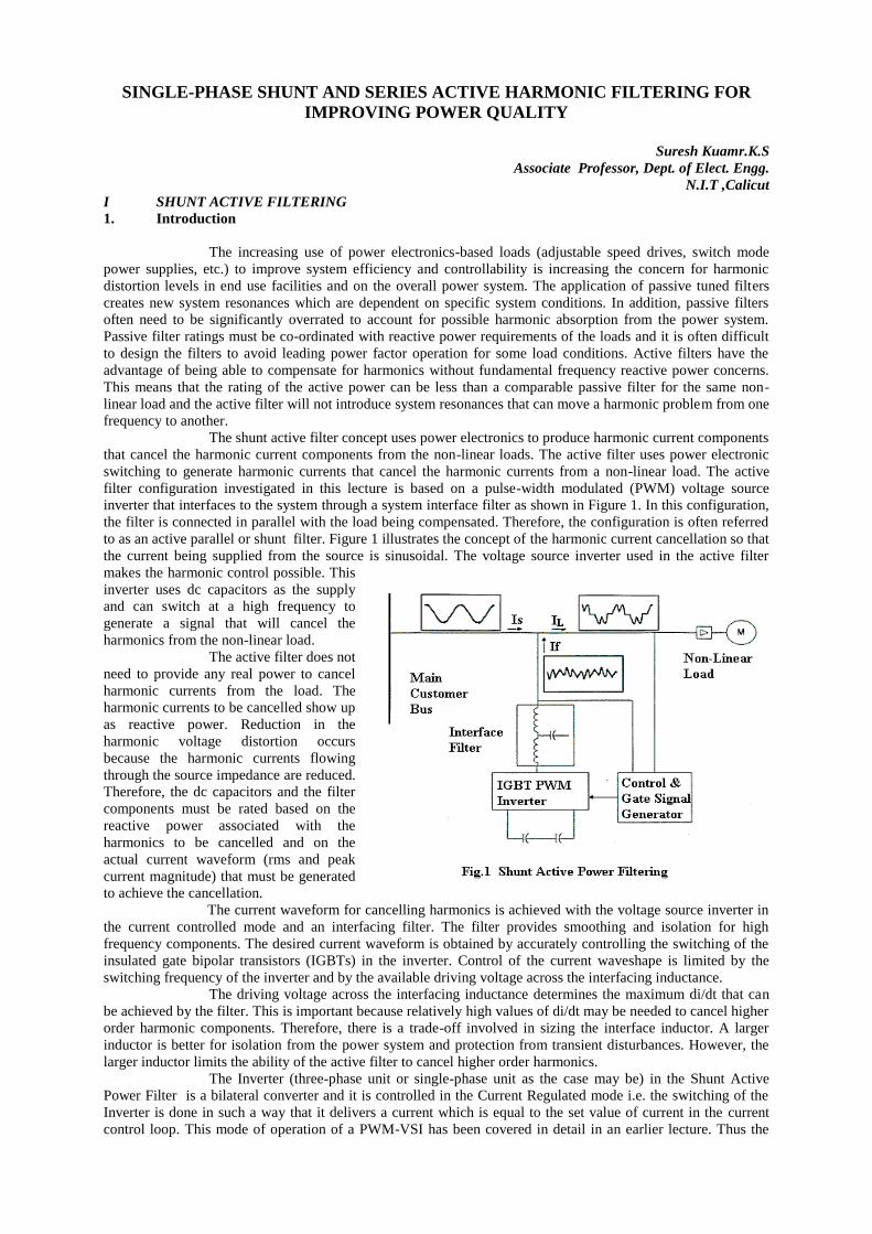
inverter that interfaces to the system through a system interface filter as shown in Figure 1. In this configuration,
the filter is connected in parallel with the load being compensated. Therefore, the configuration is often referred
to as an active parallel or shunt filter. Figure 1 illustrates the concept of the harmonic current cancellation so that
the current being supplied from the source is sinusoidal. The voltage source inverter used in the active filter
makes the harmonic control possible. This
inverter uses dc capacitors as the supply
and can switch at a high frequency to
generate a signal that will cancel the
harmonics from the non-linear load.
The active filter does not
need to provide any real power to cancel
harmonic currents from the load. The
harmonic currents to be cancelled show up
as reactive power. Reduction in the
harmonic voltage distortion occurs
because the harmonic currents flowing
through the source impedance are reduced.
Therefore, the dc capacitors and the filter
components must be rated based on the
reactive power associated with the
harmonics to be cancelled and on the
actual current waveform (rms and peak
current magnitude) that must be generated
to achieve the cancellation.
The current waveform for cancelling harmonics is achieved with the voltage source inverter in
the current controlled mode and an interfacing filter. The filter provides smoothing and isolation for high
frequency components. The desired current waveform is obtained by accurately controlling the switching of the
insulated gate bipolar transistors (IGBTs) in the inverter. Control of the current waveshape is limited by the
switching frequency of the inverter and by the available driving voltage across the interfacing inductance.
The driving voltage across the interfacing inductance determines the maximum di/dt that can
be achieved by the filter. This is important because relatively high values of di/dt may be needed to cancel higher
order harmonic components. Therefore, there is a trade-off involved in sizing the interface inductor. A larger
inductor is better for isolation from the power system and protection from transient disturbances. However, the
larger inductor limits the ability of the active filter to cancel higher order harmonics.
The Inverter (three-phase unit or single-phase unit as the case may be) in the Shunt Active
Power Filter is a bilateral converter and it is controlled in the Current Regulated mode i.e. the switching of the
Inverter is done in such a way that it delivers a current which is equal to the set value of current in the current
control loop. This mode of operation of a PWM-VSI has been covered in detail in an earlier lecture. Thus the
basic principle of Shunt Active Power Filter is that it generates a current equal and opposite in polarity to the
harmonic current drawn by the load and injects it to the point of coupling thereby forcing the source current to be
pure sinusoidal. This type of Shunt Active Power Filter is called the Current Injection Type APF.
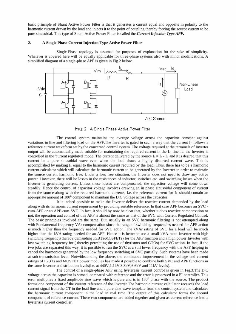
2. A Single Phase Current Injection Type Active Power Filter
Single-Phase topology is assumed for purposes of explanation for the sake of simplicity.
Whatever is covered here will be equally applicable for three-phase systems also with minor modifications. A
simplified diagram of a single-phase APF is given in Fig.2 below.
The control system maintains the average voltage across the capacitor constant against
variations in line and filtering load on the APF.The Inverter is gated in such a way that the current IL follows a
reference current waveform set by the concerned control system. The voltage required at the terminals of Inverter
output will be automatically made suitable for maintaining the required current in the Lf line,i.e. the Inverter is
controlled in the 'current regulated' mode. The current delivered by the source Is = Io - IL and it is desired that this
current be a pure sinusoidal wave even when the load draws a highly distorted current wave. This is
accomplished by making IL equal to the harmonic current required by the load. Thus, there has to be a harmonic
current calculator which will calculate the harmonic current to be generated by the Inverter in order to maintain
the source current harmonic free. Under a loss free situation, the Inverter does not need to draw any active
power. However, there will be losses in the resistances of inductor, switches etc. and switching losses when the
Inverter is generating current. Unless these losses are compensated, the capacitor voltage will come down
steadily. Hence the control of capacitor voltage involves drawing an in phase sinusoidal component of current
from the source along with the required harmonic currents, i.e. the reference current for IL should contain an
appropriate amount of 1800 component to maintain the D.C voltage across the capacitor.
It is indeed possible to make the Inverter deliver the reactive current demanded by the load
along with its harmonic current requirement by providing suitable reference. In that case APF becomes an SVC -
cum-APF or an APF-cum-SVC. In fact, it should by now be clear that, whether it does reactive compensation or
not, the operation and control of this APF is almost the same as that of the SVC with Current Regulated Control.
The basic principles involved are the same. But, usually in an SVC harmonic filtering is not attempted along
with Fundamental frequency VAr compensation since the range of switching frequencies needed for APF action
is much higher than the frequency needed for SVC action. The kVAr rating of SVC for a load will be much
higher than the kVA rating needed for an APF. Hence it is better to use a small kVA rated Inverter with high
switching frequency(thereby demanding IGBTs/MOSFETs) for the APF function and a high power Inverter with
low switching frequency for ( thereby permitting the use of thyristors and GTOs) for SVC action. In fact, if the
two jobs are separated this way, it is possible to run the SVC at a still lower frequency with the APF helping to
cancel the harmonics generated by the low frequency switching of SVC partially. Such systems have been made
at sub-transmission level. Notwithstanding the above, the continuous improvement in the voltage and current
ratings of IGBTs and MOSFET power modules has made it possible to combine both SVC and APF functions in
the same Inverter at distribution levels(i.e. at 440V,1.1kV,3.3kV,6.6kV and 11kV levels).
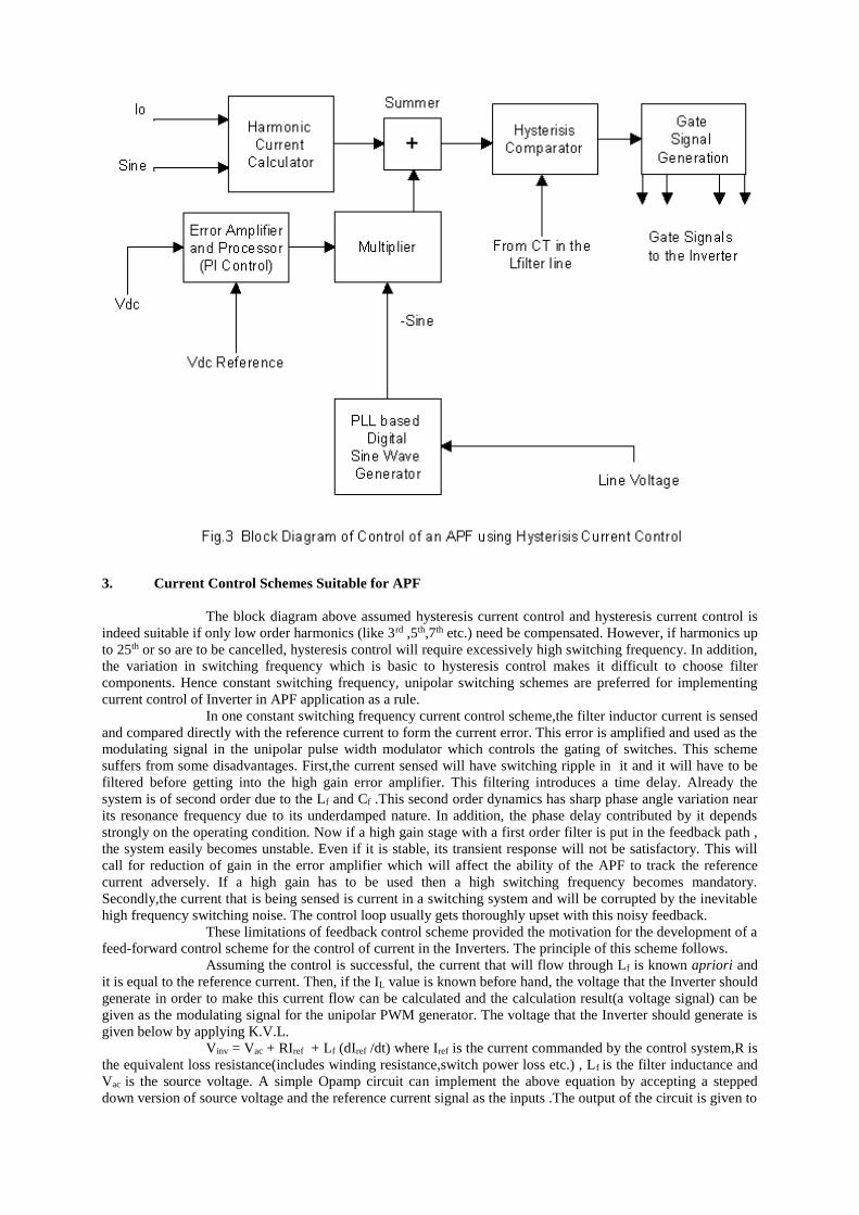
The control of a single-phase APF using hysteresis current control is given in Fig.3.The D.C
voltage across the capacitor is sensed, compared with reference and the error is processed in a PI controller. This
error multiplies a fixed amplitude sine wave which is pure and is in 1800 phase with the source. The product
forms one component of the current reference of the Inverter.The harmonic current calculator receives the load
current signal from the CT in the load line and a pure sine wave template from the control system and calculates
the harmonic current component in the load in real time. The output of this calculator forms the second
component of reference current. These two components are added together and given as current reference into a
hysterisis current controller.
3. Current Control Schemes Suitable for APF
The block diagram above assumed hysteresis current control and hysteresis current control is
indeed suitable if only low order harmonics (like 3rd ,5th,7th etc.) need be compensated. However, if harmonics up
to 25th or so are to be cancelled, hysteresis control will require excessively high switching frequency. In addition,
the variation in switching frequency which is basic to hysteresis control makes it difficult to choose filter
components. Hence constant switching frequency, unipolar switching schemes are preferred for implementing
current control of Inverter in APF application as a rule.
In one constant switching frequency current control scheme,the filter inductor current is sensed
and compared directly with the reference current to form the current error. This error is amplified and used as the
modulating signal in the unipolar pulse width modulator which controls the gating of switches. This scheme
suffers from some disadvantages. First,the current sensed will have switching ripple in it and it will have to be
filtered before getting into the high gain error amplifier. This filtering introduces a time delay. Already the
system is of second order due to the Lf and Cf .This second order dynamics has sharp phase angle variation near
its resonance frequency due to its underdamped nature. In addition, the phase delay contributed by it depends
strongly on the operating condition. Now if a high gain stage with a first order filter is put in the feedback path ,
the system easily becomes unstable. Even if it is stable, its transient response will not be satisfactory. This will
call for reduction of gain in the error amplifier which will affect the ability of the APF to track the reference
current adversely. If a high gain has to be used then a high switching frequency becomes mandatory.
Secondly,the current that is being sensed is current in a switching system and will be corrupted by the inevitable
high frequency switching noise. The control loop usually gets thoroughly upset with this noisy feedback.
These limitations of feedback control scheme provided the motivation for the development of a
feed-forward control scheme for the control of current in the Inverters. The principle of this scheme follows.
Assuming the control is successful, the current that will flow through Lf is known apriori and
it is equal to the reference current. Then, if the IL value is known before hand, the voltage that the Inverter should
generate in order to make this current flow can be calculated and the calculation result(a voltage signal) can be
given as the modulating signal for the unipolar PWM generator. The voltage that the Inverter should generate is
given below by applying K.V.L.
Vinv = Vac + RIref + Lf (dIref /dt) where Iref is the current commanded by the control system,R is
the equivalent loss resistance(includes winding resistance,switch power loss etc.) , Lf is the filter inductance and
Vac is the source voltage. A simple Opamp circuit can implement the above equation by accepting a stepped
down version of source voltage and the reference current signal as the inputs .The output of the circuit is given to

the unipolar PWM circuit after suitable scaling. Then the Inverter generates the right voltage and hence the
current in Lf will have to be Iref.
However, this requires the knowledge of accurate values of R and Lf.The value of R is
operating point dependent (through switch power losses) and can not be known accurately. If these values are
precisely known the current control would have been 'free of dynamics' i.e.,the bandwidth of current control loop
would have been infinite. But there are inaccuracies in the estimation of the parameters and inaccuracies in the
measurement of Vac.Also the differentiator operation has to be band limited in practise due to the well known
sensitivity of differentiator to noise and high frequency signals. These imperfections make the current control
logic deviate from the ideal and a small amount of actual current feedback will be needed along with the other
components to correct the minor deviations. However, now the role of current feedback is only to correct second
order effects and hence can be of low gain. Moreover, for the same reason no filtering is needed in the feedback
path. With this term added ,the Inverter voltage control equation becomes:
Vinv = Vac + RIref + Lf (dIref /dt) +K ( Iref - IL ) where K is the feedback gain and is usually very
small. This scheme is capable of rise time of 50s -250 s and yields a high bandwidth current control loop
which is highly desirable in APF since APF is expected to track up to 25th harmonic and more.
K is the feedback gain,Kpwm is the gain of Inverter and Z0(s) is the equivalent load impedance
connected at the a.c source point.
4. The D.C Voltage Control Loop
The D.C voltage control loop in APF is similar to the D.C control loop of Active Line
Conditioners or PWM Rectifiers , Static VAr Compensators etc, and similar considerations apply.
The instantaneous power input into the inverter (due to harmonic currents, fundamental active
current needed to supply the inverter losses and fundamental reactive power if static VAr compensation is also
being performed) from mains will get balanced by (i) the dissipation in the inverter and capacitor (ii) the rate of
change of stored energy in the inverter passive filter reactive elements and (iii) rate of change of stored energy in
the DC Side Capacitor. The inverter losses and the power that goes into changing the energy storage in the small
filter elements may be ignored in a first order qualitative analysis and we may say that to a good approximation
the instantaneous power that goes into the inverter reaches the DC Side capacitor. Fundamental current flow
(which will be a small active component if no shunt Var compensation is being done) will result in second
harmonic pulsations in the inverter input power and this should lead to second harmonic voltage components
appearing across DC side capacitor. Harmonic current flow into inverter similarly will give rise to higher
harmonic voltage ripples in the DC Side Capacitor. The second harmonic ripple in voltage across the DC Side
capacitor can cause some difficulty in the DC voltage control loop. The problem becomes significant if the
inverter is doing VAr control as well as harmonic control.
When the DC Side voltage is sensed , compared with a set reference and the error is amplified
the second harmonic (and higher harmonics in capacitor voltage) get amplified and appear at the output of the
K
R/KsKpwm
(Lf/KsKpwm)d/dt
Kpwm
R
Ks1/sLf
Zo(s)1/Kpwm
+
+
+ + +
Iref+
+ +
- -
-
+
+
+
IL
Fig.4 Feedforward Current Control Scheme
+
+
error amplifier. The second harmonic at the error amplifier output results in a third harmonic component
appearing in the reference current and this will lead to injection of third harmonic current in the line. The DC
Side voltage will have to be filtered to remove the second harmonic to prevent this. This filtering will invariably
slow down the DC voltage control loop which in turn will call for a higher value of DC side capacitance.
However, since the 50 Hz current in the Inverter line of an APF is small ,the DC side capacitor
will not have much second harmonic ripple and hence not much filtering is required on this voltage before it gets
into the control loop if the APF will never be required to do static VAr compensation too. By the same reason,
the D.C loop control can be faster in APF compared to APLC,SVC or Switched Mode Rectifier.
5. The Harmonic Current Calculator
This is the most important component in the control system. It accepts the load current and
sinusoidal templates from the PLL-Sine wave generator and returns the value of harmonic content of the load
current for further control purposes. The D.C side capacitor should not be asked to supply even a fraction of the
active power required by the load since it will run down rapidly if that happens. Hence, the Calculator must
ensure that neither under steady state nor under load transient conditions the calculated current will contain an
active fundamental component. However, it is not possible to ensure this under transient conditions strictly. Then
the Calculator must reduce the active component to zero as fast as possible. Any delay on the part of this
Calculator in removing the active power component in its output will be translated as higher and higher value for
the D.C side capacitor especially considering the unavoidable filtering in the DC voltage control loop.
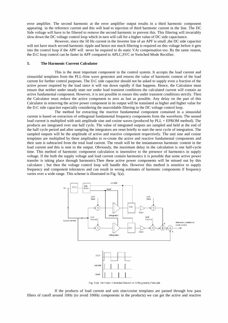
The method for extracting the reactive fundamental component contained in a sinusoidal
current is based on extraction of orthogonal fundamental frequency components from the waveform. The sensed
load current is multiplied with unit amplitude sine and cosine waves (produced by PLL + EPROM method). The
products are integrated over one half cycle. The value of integrated outputs are sampled and held at the end of
the half cycle period and after sampling the integrators are reset briefly to start the next cycle of integration. The
sampled outputs will be the amplitude of active and reactive component respectively. The unit sine and cosine
templates are multiplied by these amplitudes to re-create the active and reactive fundamental components and
their sum is subtracted from the total load current. The result will be the instantaneous harmonic content in the
load current and this is sent to the output. Obviously, the maximum delay in the calculation is one half-cycle
time. This method of harmonic component calculation is insensitive to the presence of harmonics in supply
voltage. If the both the supply voltage and load current contain harmonics it is possible that some active power
transfer is taking place through harmonics.Then these active power components will be missed out by this
calculator ; but then the voltage control loop will handle this. However this method is sensitive to supply
frequency and component tolerances and can result in wrong estimates of harmonic components if frequency
varies over a wide range. This scheme is illustrated in Fig. 5(a).
If the products of load current and unit sine/cosine templates are passed through low pass
filters of cutoff around 10Hz (to avoid 100Hz components in the products) we can get the active and reactive
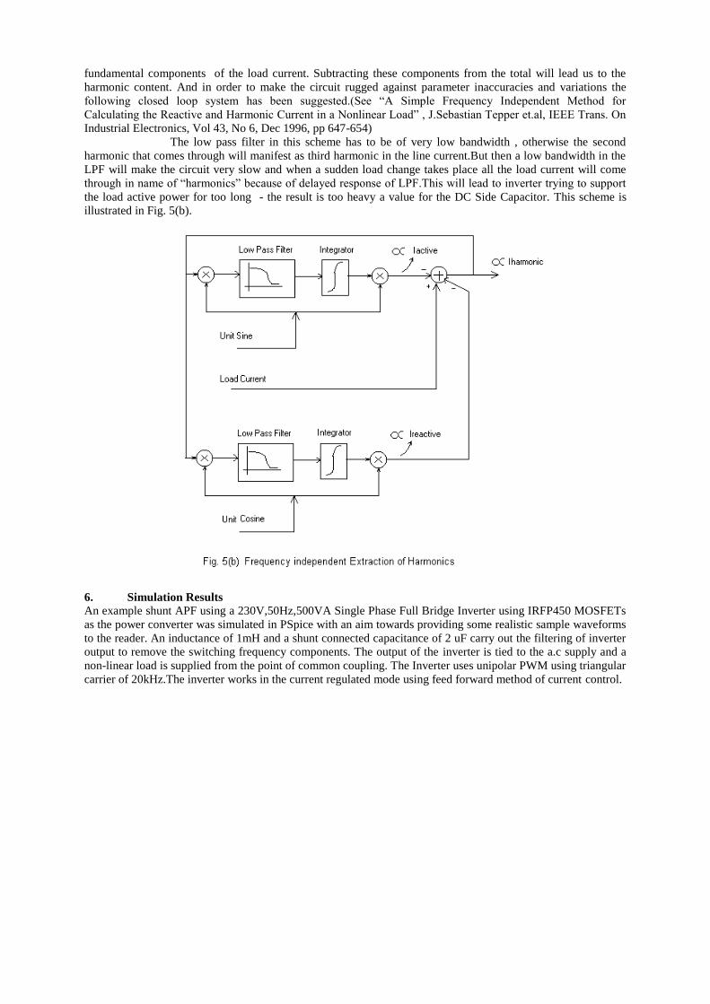
fundamental components of the load current. Subtracting these components from the total will lead us to the
harmonic content. And in order to make the circuit rugged against parameter inaccuracies and variations the
following closed loop system has been suggested.(See “A Simple Frequency Independent Method for
Calculating the Reactive and Harmonic Current in a Nonlinear Load” , J.Sebastian Tepper et.al, IEEE Trans. On
Industrial Electronics, Vol 43, No 6, Dec 1996, pp 647-654)
The low pass filter in this scheme has to be of very low bandwidth , otherwise the second
harmonic that comes through will manifest as third harmonic in the line current.But then a low bandwidth in the
LPF will make the circuit very slow and when a sudden load change takes place all the load current will come
through in name of “harmonics” because of delayed response of LPF.This will lead to inverter trying to support
the load active power for too long - the result is too heavy a value for the DC Side Capacitor. This scheme is
illustrated in Fig. 5(b).
6. Simulation Results
An example shunt APF using a 230V,50Hz,500VA Single Phase Full Bridge Inverter using IRFP450 MOSFETs
as the power converter was simulated in PSpice with an aim towards providing some realistic sample waveforms
to the reader. An inductance of 1mH and a shunt connected capacitance of 2 uF carry out the filtering of inverter
output to remove the switching frequency components. The output of the inverter is tied to the a.c supply and a
non-linear load is supplied from the point of common coupling. The Inverter uses unipolar PWM using triangular
carrier of 20kHz.The inverter works in the current regulated mode using feed forward method of current control.
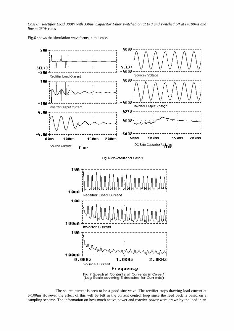
Case-1 Rectifier Load 300W with 330uF Capacitor Filter switched on at t=0 and switched off at t=100ms and
line at 230V r.m.s
Fig.6 shows the simulation waveforms in this case.
The source current is seen to be a good sine wave. The rectifier stops drawing load current at
t=100ms.However the effect of this will be felt in the current control loop since the feed back is based on a
sampling scheme. The information on how much active power and reactive power were drawn by the load in an
a.c cycle will be available only at the end of that cycle in the harmonic current calculator block. In other words
there is a maximum of one cycle delay between change in load current and change in the harmonic current
calculated by the harmonic current calculator. Hence the source current continues to be at the same old level for
one more cycle after the 100ms point. But, now since there is no load to absorb this power it will go into inverter
and charge up the d.c side capacitor. This is clearly seen in the capacitor voltage waveform. The set value of
capacitor voltage is 400V and as the capacitor approaches that level the source current tapers down to zero. Close
examination of the source voltage and source current waveforms reveal that there is a sudden phase change of
180 deg in source current at 120ms and that after that time point the power flow is into the source. It is as it
should be since the capacitor is overcharged now and the system has to pump energy back into the source in
order to bring the capacitor back to its set value.
Fig.7 shows the spectral analysis of the relevant currents when the 300W rectifier was drawing
power. The low frequency harmonics in source current are in the 10-50mA range indicating almost pure sine
wave current. Note that the inverter current and the rectifier current are harmonic rich.
The simulation model employed makes an assumption that whatever voltage is demanded of
the inverter by the current regulation loop can really be synthesised by the inverter. This is not true. The
maximum voltage that an inverter can synthesise is equal to the d.c side voltage theoretically. But there are
restrictions on minimum and maximum pulse widths that can be realised in an inverter practically. Due to these
restrictions the practical inverter can utilise only a maximum of 95% of d.c voltage. These practical limits are
ignored in this simulation and it is assumed that the inverter can utilise the d.c side voltage fully. This is why
there is a limiter set at 380V in the inverter model. This assumes that d.c side is maintained at 400V.But during
transients d.c voltage varies. Hence after simulation run is over the result should be checked to see that at no time
the inverter synthesised voltage was above the capacitor voltage. In case-1 the maximum inverter demand was
360V and the capacitor voltage never went below 382Volts.Hence the simulation results for case-1 will be
acceptable.
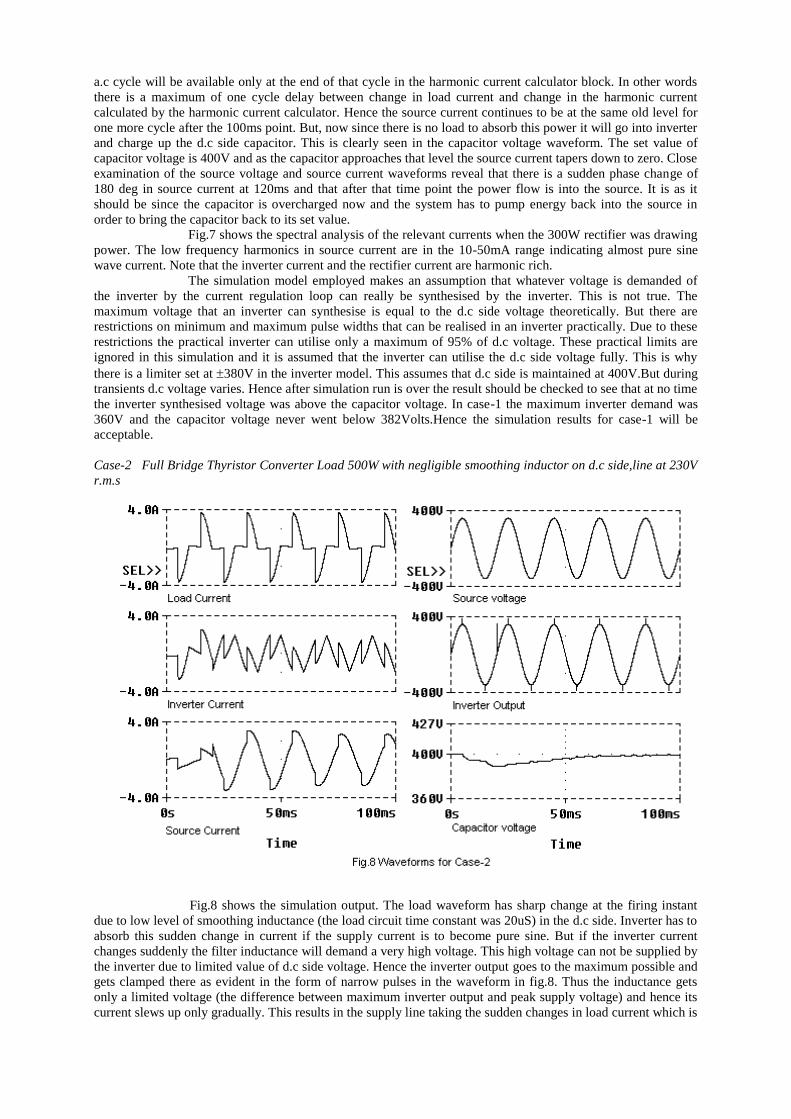
Case-2 Full Bridge Thyristor Converter Load 500W with negligible smoothing inductor on d.c side,line at 230V
r.m.s
Fig.8 shows the simulation output. The load waveform has sharp change at the firing instant
due to low level of smoothing inductance (the load circuit time constant was 20uS) in the d.c side. Inverter has to
absorb this sudden change in current if the supply current is to become pure sine. But if the inverter current
changes suddenly the filter inductance will demand a very high voltage. This high voltage can not be supplied by
the inverter due to limited value of d.c side voltage. Hence the inverter output goes to the maximum possible and
gets clamped there as evident in the form of narrow pulses in the waveform in fig.8. Thus the inductance gets
only a limited voltage (the difference between maximum inverter output and peak supply voltage) and hence its
current slews up only gradually. This results in the supply line taking the sudden changes in load current which is

clearly visible in the supply current waveform in Fig.8.Thyristor converter fed resistive load is the most
demanding load on an Active Power Filter and waveform improvement on supply side will be only partial as
illustrated in this case study.
In this case also the capacitor voltage was verified to be above the inverter output at all time
and hence simulation results are acceptable.
Case-3 Same as in case – 2 but the load circuit time constant was changed to 200uS.
Fig.9 shows the relevant waveforms in this case. The source current is seen to be almost pure
sine wave in this case.
7. Determining Active Filter Ratings for Non-linear Load Types
One of the confusing aspects of applying active filters is trying to figure out the active filter
rating that is required to compensate for the harmonics from a particular load. A parallel-connected active filter
should be rated in terms of the rms current it can provide. Then the task is to figure out the rms current required
to compensate for the harmonics from different types of loads. Simulations will be needed for a number of
typical non-linear loads to develop some guidelines for active filter ratings.
One advantage of the parallel-connected active filter, as compared to passive filters, is that it is
self-limiting in terms of the harmonic cancellation provided. There is no concern for overloading the filter due to
harmonics from the utility supply system or under- rating the filter for the loads involved. The worst case
scenario if the filter is under-rated is that it just won't completely compensate for all the non-linear load current
harmonics. In fact, it may not be necessary to compensate for all the harmonics from a non-linear load. With the
active filter, the size can be selected to achieve any desired level of cancellation. One good way to use this
concept would be to provide only enough compensation so that the load/filter compensation was within some
specified guidelines for harmonic generation (e.g. IEEE 519-1992).
8. Effect of Load Waveform on Filtering Effectiveness
The effectiveness of the active filter in compensating for harmonic components of the load
current depends on the specific load current waveform involved. Two different waveforms may have the same
rms harmonic content but the active filter may do a better job of compensating for one of the waveforms because
of the waveshapes involved.

An ac
voltage regulator is used for
illustration. Two cases are
compared in Figure 10. The
only difference between the
two cases is the load of the
ac regulator. In the
waveforms on the left side
of the figure, the load is a
pure resistance. The
waveforms on the right side
are for the case where the
load is a series combination
of resistance and reactance.
The performance is much
better for the smoother load
current waveform (RL
load). It is worthwhile to
note that the majority of
applications for the active
filter will involve
waveforms like those on the
right hand side of Figure 10
(e.g. adjustable speed drives
with diode bridge rectifiers or Fig.10 APF Performance for an a.c voltage regulator with R & R-L Load
single phase electronic loads),
rather than the left side.
In general, the current waveform of an ac regulator with resistive load is an example of the
waveshape that poses the severest challenge for an active filter. The problem is the high di/dt that is required of
the filter to compensate for the high di/dt at turn on of the regulator. The problem is most severe when the
regulator is turned on with a firing angle close to 90 degrees because this is when the available driving voltage
stored on the dc capacitor is at a minimum. The output di/dt capability can be raised either by increasing the dc
voltage setting or by reducing the size of the interfacing inductance. The limiting factor for increasing the dc
voltage is the voltage withstand capability of the IGBT devices. The limiting factors for reducing the interfacing
inductance include the IGBT di/dt withstand capability, control requirements, the interface passive filter
requirement, and overall system stability. If the interfacing inductance becomes too small, the dc voltage cannot
be kept constant for normal operation.
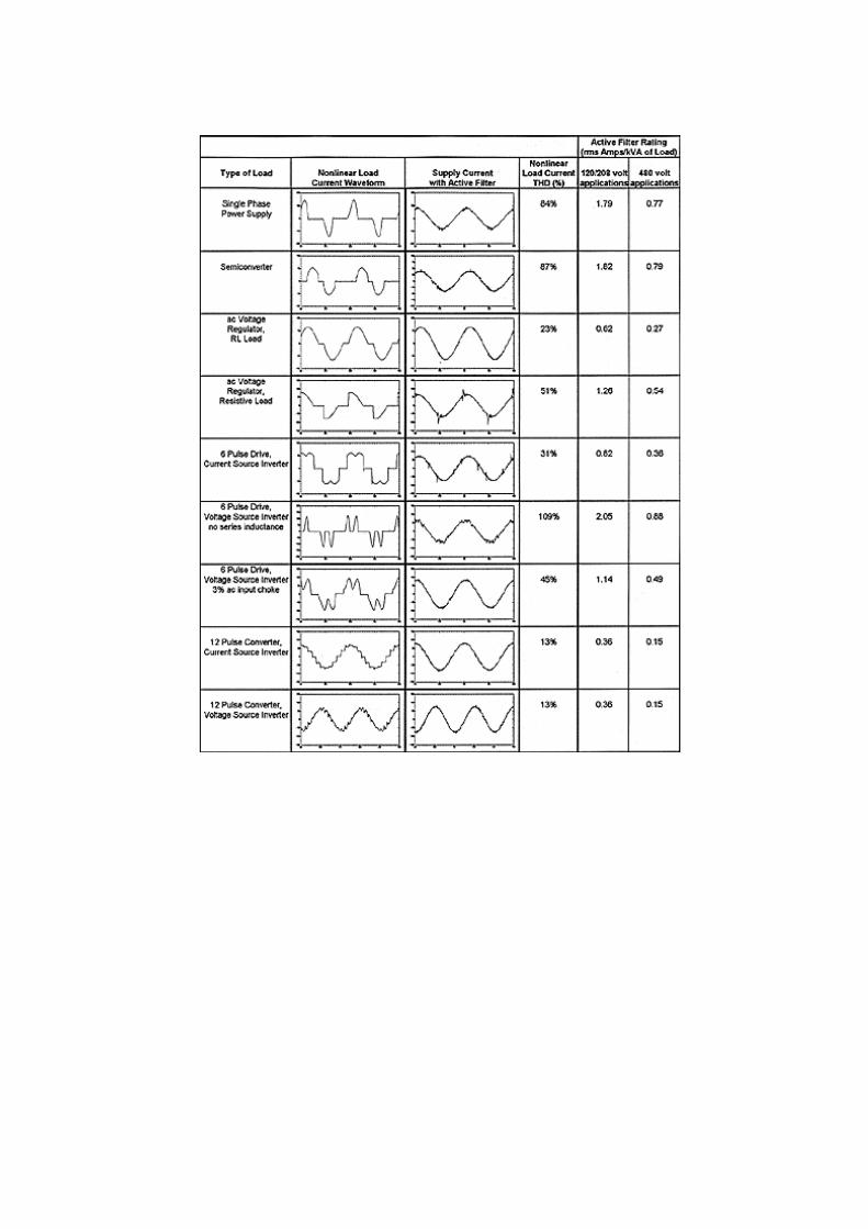
9. Steady-State Rating Requirements
The best way to provide a rating for an active filter is in terms of the rms current that it must
provide to compensate for harmonics from non-linear loads. Table1 provides a convenient summary of different
non-linear load types with example waveforms and typical levels of harmonic current distortion associated with
each load. Using these typical waveforms, it is possible to calculate a theoretical value for the required harmonic
compensation from the active filter. The summary includes the THD for each non-linear load waveform and the
required active filter rating in rms amps per kVA of load rating. These ratings assume that the active filter rating
should be based on the total rms harmonic current content of the load. A simulation waveform illustrating the
active filter effectiveness for each of these waveforms is also provided. The ratings in Figure 11 (next page)
assume ideal active filter characteristics. That is, they assume that the active filter can compensate for every amp
of harmonic current created by the non-linear load.
II. HARMONIC VOLTAGE CANCELLATION & ISOLATION BY SERIES ACTIVE
POWER FILTERING (SPAF) IN DISTRIBUTION SYSTEMS
1. Introduction
In Shunt Active Power Filtering ,the Inverter injects harmonic currents required for elimination
of harmonics in the source current and injects it at the node where the load is connected. The current drawn by
the Inverter is forced to contain a small in-phase sinusoidal component in order to draw enough active power
from source to supply losses in the APF and to maintain the D.C side capacitor voltage constant. Series APF is
the dual of Shunt APF.
In Series APF the Inverter injects a voltage in series with the line which feeds the polluting
load through a transformer. The injected voltage will be mostly harmonic with a small amount of sinusoidal
component which is in-phase with the current flowing in the line. The small sinusoidal in-phase (with line
current) component in the injected voltage results in the right amount of active power flow into the Inverter to
compensate for the losses within the Series APF and to maintain the D.C side capacitor voltage constant.
Obviously, the D.C voltage control loop will decide the amount of this in-phase component.
Depending upon the location of Series APF, nature of bus voltage and nature of load the
purpose of injecting harmonic voltage in series with the line can be one of the following.
(i) In this case the distribution bus (say 11 kV) is polluted and has non-negligible harmonic
content. It is required to clean up this voltage before it reaches sensitive loads. Essentially we want to
remove the harmonic content in the voltage at the distribution substation before it is fed into a feeder
supplying harmonic-sensitive loads. The bus voltage corruption may have been due to harmonic current
generating loads upstream. However, the Series APF is not aimed at that harmonic generation problem;
but is applied to protect other chosen loads from the already present harmonics in the source bus. In this
mode ,the Series APF senses the bus voltage and line currents and injects the right amount of harmonic
voltages in series with the line in such a way that the voltages after the filter will be harmonic free and
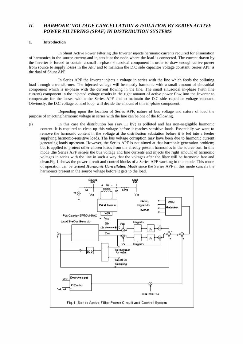
clean.Fig.1 shows the power circuit and control blocks of a Series APF working in this mode. This mode
of operation can be termed Harmonic Cancellation Mode since the Series APF in this mode cancels the
harmonics present in the source voltage before it gets to the load.
(ii) In the second context, a Series APF is used to help a shunt connected Passive Filter in diverting the
harmonic currents generated by a non-linear load. Tuned LC filters are supposed to have zero
impedance at the tuning frequency. However, they will have non-zero value due to losses in the
inductor. Hence, the tuned filter shares the harmonic current with the line and source impedance instead
of absorbing it entirely. Moreover, the filter is easily detuned with ageing of components and
degradation in capacitors. In addition, changes in system frequency make the filter detuned. If the filter
is detuned, the harmonic current generated by the non-linear load will flow in the source path partially
thereby reducing the filtering effectiveness of the Passive Filter.One way to increase the effectiveness of
the Passive Filter and make it absorb all the harmonic current is to insert a high impedance in series
with the line (source) before the load. Of course, this high impedance should be there only for harmonic
current flow and it should go to a zero value for fundamental current flow.
The Series APF in this mode of operation, senses the harmonic current flow in the line and
forces the Inverter to inject (through a transformer) a harmonic voltage proportional to this current in
series with the source in direction to oppose the current flow-in short the Series APF simulates a high
resistance in series with the line for harmonic currents alone. With this high resistance in the source
side, the Passive Filter is forced to absorb all the harmonic current generated by the load even if it has a
non zero impedance at the harmonic frequency due to detuning.
Of course, the load voltage will become distorted if the filter impedance is not zero. Moreover,
a single tuned LC filter will take care of only one harmonic component. It needs multiple LC filters to
handle all the major harmonics. All the LC sections will derive benefit from the same Series APF.If
there are harmonic components which the Passive Filters can not absorb without distorting load bus
voltage beyond acceptable levels, they will have to be permitted to flow into the source by Series APF
presenting a low or zero resistance those frequency components. The Series APF used in this mode of
operation is called Harmonic Isolator since it isolates the source bus at h frequencies from the polluting
load.
2. The Series APF in Harmonic Cancellation Mode
Fig.1 shows a Series APF in this mode. The source VS and inductance LS represent the
Thevenin's equivalent of the power system behind the distribution bus. Vsb is the source bus voltage which
contains harmonics. Lline represents the line inductance of the feeder feeding the load bus.Vlb is the load bus
voltage.The Series APF injects Vi in series with the line as shown.Single-Phase topology is considered in the
interest of simplicity.
The line current I is sensed by a CT and converted to electronic level and is fed into a PLL-
Counter-EPROM-DAC type sine wave generator.This block generates unit amplitude pure Sine wave which is in
phase with the feeder line current.It also outputs a unit amplitude Cosine wave.The harmonic content of the
source bus voltage (and thereby the voltage that the APF must inject into line) can be found out by subtracting
the fundamental component of bus voltage from the total bus voltage.This requires the extraction of fundamental
component.
The sensed bus voltage is multiplied with unit Sine and Cosine respectively to extract the
fundamental orthogonal components of voltage.The products are integrated for a cycle duration and the value of
integrals is noted by a sample and hold mechanism at the end of cycle period.After sampling the integrators are
reset and allowed to perform the integration for the next period.The sampled values will give the amplitude of in-
phase and quadrature (with respect to line current) fundamental components of voltage.These amplitudes are
multiplied with appropriate sinusoidal templates and added to re-construct the net fundamental component of
voltage and then it subtracted from the total bus voltage to get the harmonic content.
The D.C side capacitor voltage will discharge down to zero unless sufficient power is drawn
from the line to meet the losses in the Inverter.This power is drawn by injecting a fundamental in-phase
component against the line current flow. The amount of this component is decided by a PI controller which
monitors the D.C bus voltage.
The Inverter in the Series APF carries the full line current (after transformation). But the
voltage generated at the output has only a small fundamental component and has mostly harmonic components
(usually 5th,7th,11th etc.).Therefore the a.c side power in the inverter will be at 4th,6th,8th harmonic etc. Thus, the
reactive power flow into the D.C. side capacitor is at those frequencies and the ripple across the capacitor can be
made small due to high frequency nature of these power components. Also, the kVA rating of Inverter and D.C
side capacitor will be decided by the harmonic content in the voltage and the maximum line current.
The control system design considerations for the D.C. voltage control loop has been described
already described in other contexts (SVC,Shunt APF,PWM Rectifier etc.) and need not be repeated here. The

crucial control block in this application is the harmonic content calculator. The calculator has to ensure that the
output from it does not contain any in-phase component. If it contains that the capacitor will either discharge fast
or overcharge and in order to limit the change in capacitor voltage before the voltage control loop can act ,it will
be necessary to use large valued capacitor. The calculator will ensure that there is no fundamental component in
its output under steady conditions. But under transient conditions (change in line current, changes in bus voltage
etc.), it may output fundamental component. The value of D.C side capacitor will be decided almost entirely by
the dynamic response of this Calculator block.
The most difficult thing about a Series APF is to protect it. Note that it is in series with the line
and has to carry all the load current (fundamental plus harmonic, if any) .Moreover,the fault currents also will
pass through it. It is not enough to shut down the Inverter based on fast over current sensing because if the
Inverter is shut down the transformer primary goes open and secondary imposes a large impedance in series with
the line. A Series APF is to be shorted to take it out of service i.e. it has to be taken out of line and a sort path has
to be put in its place. This can call for fast acting static transfer switches.
The Series APF effectively cancels the entire harmonic content of source bus voltage. Now
what if the load at the load bus is non-linear ? The harmonic currents drawn by the load via the line will flow
through the Thevenin's impedance of the source (Ls) and produce further harmonic voltages at the source bus.
But these also will get cancelled by the Series APF.i.e. the Series APF makes the harmonic impedance to its left
side zero. Hence the harmonic impedance of the line plus source is reduced by Series APF and any shunt filter
put at the load bus will have to compete with a lower harmonic impedance in the harmonic current sharing
process. In particular ,if this Series APF is installed at the load bus i.e. after the line ,a passive shunt filter
(like capacitor or tuned LC etc.) is going to be completely useless and all the harmonic current will go into the
line,thereby corrupting the voltage received by other loads which are not protected by a Series APF.Of course
it is possible to install a Shunt Active Filter at the load bus to cancel the harmonic currents taken by load.
3. The Series APF as a Reactance Compensator
In the last section ,it was pointed out that the harmonic voltage calculator has the in-phase and
out-of-phase sine waves available to it in order to arrive at an estimate of net fundamental component in the
voltage. The injected voltage is harmonic plus a little in-phase fundamental component required to draw the loss
power. Now,if the injected voltage reference is made to have a sinusoidal component which is in quadrature with
line current , the Series APF will absorb or deliver fundamental frequency reactive power. It becomes a series
reactive power compensator or equivalently it becomes a reactance at fundamental frequency. Series APF in this
mode can provide series capacitor/inductor compensation to the line along with harmonic cancellation. The
required voltage reference can be obtained using the Cosine wave template already available in the control
system. Of course, the kVA rating of Inverter and other components will have to be suitably chosen.
This series compensation capability can be made use of in two ways. In one case, it can be
controlled in such a way that it injects a fundamental voltage in quadrature with the line current in proportion to
the current magnitude. In that case, the Series APF becomes a fixed reactance value at fundamental frequency -
usually capacitive. The application of series capacitors in the transmission lines to improve power transfer
capability,system stability and voltage regulation is well known. Series APF can implement this series capacitor
compensation as explained above.
A second way in which the fundamental Var compensation capability of Series APF can be
employed is by using it to regulate the voltage after the Series APF location at a pre-decided value. This can be
done by sensing the voltage magnitude downstream ,comparing it with a set value,processing the error in a PI
Controller and using the error to multiply Cos (t+1800) .The product is added along with the harmonic
reference coming from the Harmonic Content Calculator to form the net reference signal for the PWM
Inverter.Thereby the value of effective capacitive reactance at fundamental frequency simulated by the Series
APF is varied to maintain a constant amplitude a.c voltage at a point after the Series APF.
In both ways of implementing the Var compensation action,it is possible to derive additional
advantage from Series APF in the form of a fault current limiting reactance (provided the Series APF has high
overload capability for short duration).When the sensed line current indicates the occurrence of a fault(either by
p.f angle or by its magnitude) the Series APF fundamental reference can be shifted from -Cos t to +Cos t.
Then the Series APF will simulate an inductive reactance and thereby limit the fault current.Series APF is used
for this function too in practice.
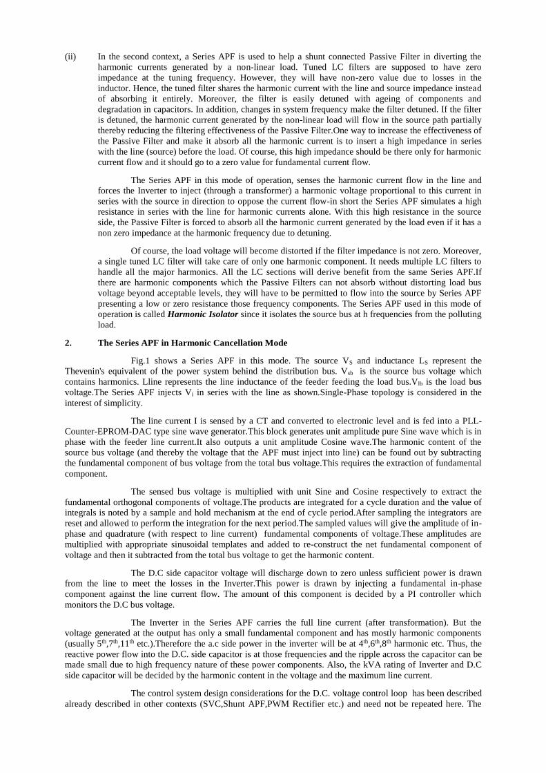
4. The Series APF in Harmonic Isolation Mode
Fig.2 shows a Series APF in harmonic isolation mode where it serves to isolate the source from
the harmonic currents drawn by the load.it does this by simulating a high resistance in series with the line for
harmonic current flow. Only one tuned passive filter is shown at the load bus and it is assumed that the load
draws one harmonic component predominantly. Otherwise more tuned filters are needed at the load bus.
The source current Is is sensed and a pure sine wave is in phase with it is generated by the PLL
subsystem. The sine thus generated is used to extract the harmonic content in the source current using the
orthogonal decomposition method which has been described in the last section. The extracted harmonic
component of Is is multiplied by a gain K and that (along with the small fundamental component needed to
draw the loss power) is given as the reference to the PWM Voltage Source Inverter.Thus,the Inverter injects a
harmonic voltage which is proportional to the harmonic current into the line ,thereby simulating a resistance of
value K ohms in the line (only for harmonic current flows).
Now, the harmonic current drawn by the load has two parallel paths to choose-through the
filter and through the line which appears as a high resistance now. It chooses filter path predominantly even if
the filter is slightly detuned. Thus, the harmonic current into the source is reduced to very low levels.
Similar action takes place in the case of harmonic content in the source. The high resistance
simulated by the Series APF will absorb all the harmonic voltages (for which there are passive filter branches
at load end) present in the source bus and isolate the load from supply side harmonics. This is a welcome
feature since in the absence of Series APF, the tuned filter would have drawn large currents from source if
there were source side harmonics. This would have led to overloading of the filter and would have called for
parallel tuned LC section in series with the line to isolate the series tuned filter from supply side harmonics.
With a series tuned LC filter,there is always a chance of system resonances due to parallel
resonance between line/source inductance and filter components. The Series APF in the resistance emulation
mode will damp these resonances well and will avoid dangerous harmonic amplification.
It is possible to combine series capacitor compensation along with harmonic isolation in this
system by suitably modifying the reference signal to the PWM Inverter.
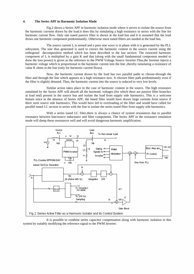
5. PSpice Simulation of a Series Active Filter in Harmonic Isolator Mode
(Also called Hybrid Active Filter)
The PSpice Simulation diagram (using Design Lab 8.0) for a Single Phase Series APF in
Harmonic Isolation mode is given below. The inverter was modelled as an ideal controlled voltage source. A
half-controlled thyristor converter is used as load.
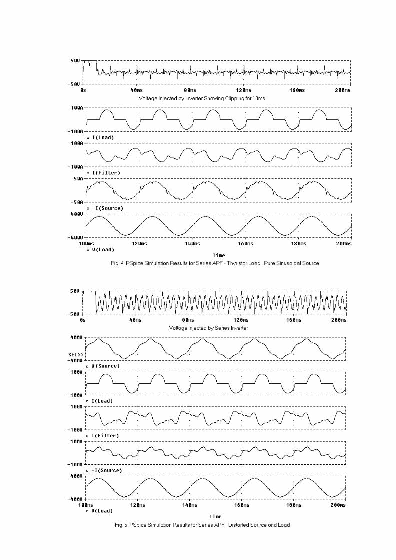
The simulation run results for a pure sinusoidal source and thyristor load is shown below in
Fig. 4.The harmonic calculator takes one half cycle to calculate the harmonic content properly, till then it outputs
all the input as the harmonic content ; this explains why the inverter had to inject maximum (limited to 50V) in
the beginning.This will lead to a large active power outflow from the DC Side of Inverter and will require a
suitably sized capacitor to hold the voltage against such outflow (or inflow) of active power.The filter is seen to
take a large leading reactive power – expected since passive filtering is practically possible only along with
passive capacitor reactive compensation.The value of inductor required for harmonic filtering alone (without
fundamental leading reactive power) will be impracticably high.The source current, though more or less
sinusoidal, shows high frequency content.This is so since the load current has high frequency content , but the
passive filter offers low impedance path only for a few harmonics.Thus the current sharing ratio between the
Series Inverter equivalent resistance (40 ohms in the simulation) and filter impedance is adversely affected at
high frequencies – leading to more of high frequency currents flowing to source side and consequent appearance
of high frequency harmonic content at the load terminal voltage.
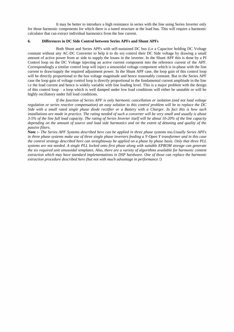
The simulation results for a distorted source containing 10% fifth harmonic is shown in Fig. 5.
Now the source current is distorted perceptibly – since the inverter has to absorb all the source fifth harmonic
across it. However the load voltage is more or less sinusoidal with a little h.f content which is due to the h.f
content in load current as eaplained above.Thus it can be seen that the Series APF handles all those load current
harmonics and source voltage harmonics for which there are tuned passive filter structures at load bus well. And
it can not handle the harmonic components for which there is no low impedance path across load bus.The
distortion reported in this simulation will be on the optimistic side due to the neglecting of switching frequency
filter of the series inverter.
It may be better to introduce a high resistance in series with the line using Series Inverter only
for those harmonic components for which there is a tuned structure at the load bus. This will require a harmonic
calculator that can extract individual harmonics from the line current.
6. Differences in DC Side Control between Series APFs and Shunt APFs
Both Shunt and Series APFs with self-sustained DC bus (i.e a Capacitor holding DC Voltage
constant without any AC-DC Converter to help it to do so) control their DC Side voltage by drawing a small
amount of active power from ac side to supply the losses in the inverter. In the Shunt APF this is done by a PI
Control loop on the DC Voltage injecting an active current component into the reference current of the APF.
Correspondingly a similar control loop will inject a sinusoidal voltage component which is in-phase with the line
current to draw/supply the required adjustment power. In the Shunt APF case, the loop gain of this control loop
will be directly proportional to the bus voltage magnitude and hence reasonably constant. But in the Series APF
case the loop gain of voltage control loop is directly proportional to the fundamental current amplitude in the line
i.e the load current and hence is widely variable with line loading level. This is a major problem with the design
of this control loop – a loop which is well damped under low load conditions will either be unstable or will be
highly oscillatory under full load conditions.
If the function of Series APF is only harmonic cancellation or isolation (and not load voltage
regulation or series reactive compensation) an easy solution to this control problem will be to replace the DC
Side with a small rated single phase diode rectifier or a Battery with a Charger. In fact this is how such
installations are made in practice. The rating needed of such a converter will be very small and usually is about
3-5% of the line full load capacity. The rating of Series Inverter itself will be about 10-20% of the line capacity
depending on the amount of source and load side harmonics and on the extent of detuning and quality of the
passive filters.
Note :- The Series APF Systems described here can be applied in three phase systems too.Usually Series APFs
in three phase systems make use of three single phase inverters feeding a Y-Open Y transformer and in this case
the control strategy described here can straightaway be applied on a phase by phase basis. Only that three PLL
systems are not needed. A single PLL locked onto first phase along with suitable EPROM storage can generate
the six required unit sinusoidal templates. Also, there are a variety of algorithms available for harmonic content
extraction which may have standard implementations in DSP hardware. One of those can replace the harmonic
extraction procedure described here (but not with much advantage in performance !)


![H2E: A Privacy Provisioning Framework for Collaborative Filtering … · 2019-09-10 · collaborative filtering, content-based filtering, and hybrid filtering [3]. Content-based filtering,](https://img.pdfslide.net/doc/110x75/5f2811153d39b70bb31af3b8/h2e-a-privacy-provisioning-framework-for-collaborative-filtering-2019-09-10-collaborative.jpg)