Embed Size (px)
Citation preview

Shunt Active Filtering in Smart Grid Distributed Generation
Systems Selie Galami, Xiaoxia Yang, Johannes Goplen Lomsdalen
Abstract: This is the report for our mini-project assignment in the course "TET4190 Power
Electronics for Renewable Energy" at NTNU, where we were to explore how distributed
resources can be used for power quality (PQ) improvement in presence of nonlinear loads,
preventing them from spreading around in the grid. The tasks became:Trying to design shunt
active filter to compensate the harmonic current in a smart distributed converter system
across the distribution level of power grid. Using Matlab simulation and Simpower to
simulate the power system and shunt active filter equipment, to check and improve the
design and relative parameter.
10/1/2012
Supervised by Phd student Mehdi Karbalaye Zadeh

Contents Section 1. Background ............................................................................................................................ 2
1 Introduction ................................................................................................................................... 2
2 Reactive compensator, active filtering ........................................................................................ 3
3 Instantaneous powers with pq-theory .......................................................................................... 4
4 Matlab simulations ........................................................................................................................ 5
Section 2. Simulation and Result ............................................................................................................ 6
Part1. Microgrid with single unit system with current control scheme .............................................. 6
Part2. Islanded mode control with single unit using both voltage and current control scheme ........ 8
Part3. Parallel inverters in islanded mode for both voltage and current control ............................... 9
Part4. Compensating with nonlinear load ......................................................................................... 11
Section 3. Conclusion ............................................................................................................................ 14
References ............................................................................................................................................. 15
Appendix ................................................................................................................................................ 16
Section 1. Background
1 Introduction 1.1 Overview
In a world craving for electric energy, where the fossil fuels and nuclear power are
considered "bad" from an environmental point of view, a variety of smaller power plants is
emerging with respect to the term “Carbon-Free Society” [3].Photovoltaic-and wind power
plants pops up around the world, wave and tidal power are under continuously development,
in addition new small-scale hydropower plants, and various sized combined heat and power
(CHP) plants are integrated into the grid. Such local enforcement of the grid using smaller
distributed resources are often connected to the grid using power electronic components,
enabling the generation frequency and the grid frequency to be completely independent of
each other. The use of power electronics gives us the ability to provide power to the grid, but
it also gives us the ability to perform system parameters restoration at its connection point.
1.2 Power electronics
Power electronics is a combination of power, electronics and control: power refers to either
the stationary or the rotatory power equipment for its generation, transmission and
distribution, while electronics is the referral to the solid state devices and circuits for signal
processing and control is the characteristics of any closed system to obtain the required
output. Hence, power electronics can be referred to as the use of electronic devices to control
power. The basic functions or importance for power electronics are:
1. Ac-dc, dc-ac ,ac-ac, dc-dc , i.e., power conversion 2. Removal of distortion, harmonics, high voltage drop(voltage dip) and over voltages, i.e., power conditioning 3. Required control of electrical parameters such as, currents, voltages, impedance and phase angle 4. Needed interruption transfer of circuit and current limiting functions
Power electronics on:
Generation:
Solar energy (photo voltaic cells) and fuel cells are examples of renew-able energy sources,
which give a dc output. If they are to be connected to the main grid, there is a need of its
conversion to ac at an appropriate frequency and voltage. Also, if its output is to be used by
dc loads itself, there is a need of different dc levels, i.e. conversion of their dc output to
another dc level of the load. Hence, power electronics can be used.
Storage:
The conversion of ac to dc for storing power in batteries, and its later use by converting it
back to ac, allows for an efficient and optimum power extraction and usage.
Distribution:
On distribution side also, there are basically two types of consumers: industrial (commercial)
and household and their energy demands are changing rapidly. This is the new challenge for
the utilities, i.e. to provide them with improved and reliable service. For different consumers,

there is a different tolerance level of voltage. Some might themselves set up UPS, inverter,
solar cells etc. on their side to meet up with their power requirements but this is inefficient
and wasteful. Hence, it is a much better solution if the utility side itself makes use of power
electronics to deliver high quality and reliable power at a cost acceptable to both parties. If not
properly designed or rated, electrical equipment will often malfunction when harmonics are
present in an electrical system.
Transmission:
The (HVDC) High Voltage Direct Current and (FACTS) Flexible AC Transmission System
(FACTS) employ power electronics for more efficient power transmission. There are a large
number of HVDC projects in operation, but due to high cost of converter stations, the scope
of HVDC is and will remain limited. Then there is FACTS technology which has its cost 10%
to 30% reduced as compared to HVDC for the same power. Hence, if variation in frequency
and long distance is not criteria to be considered, FACTS is an efficient and an inexpensive
technology as compared to HVDC. FACT technology provides:
-Control of power flow so that it flows through the designated routes.
-Increase in loading capacity of transmission lines.
-Prevention of blackouts.
-Improvement in generation productivity.
-Reduction in circulating reactive power.
2 Reactive compensator, active filtering
In earlier days, power conditioning was performed by synchronous machines performing
reactive compensation. Nowadays this is done more and more with solid state devices. There
are two ways to connect a solid state power conditioner to the grid [1]
, either in series or shunt.
As distributed generators generally are connected to the grid in a shunt connection, rather than
in series with the grid, we are here only considering the shunt connection and current
compensating.
The importance of current compensation in power system with non-linear load is as
follows: If the load is linear the current of the system will follow the waveform of the voltage,
that is the ideal condition for the grid, but practically the industrial loads are usually nonlinear
mostly because of uncontrolled rectifies which are connected to the gird in low- and medium-
voltage level. In this case, the current will be distorted with harmonic current. There are a lot
of disadvantages in the harmonic system. For example, it will increase the current in the
power system, which causes a sharp increase in the zero sequence current, and therefore
increases the current in the neutral conductor. This effect can require special consideration in
the design of an electric system to serve non-linear loads. In addition to the increased line
current, different pieces of electrical equipment can suffer effects from harmonics on the
power system [7]. And even more it will cause the distortion of the voltage waveform at the
loads and power quality problems [8]. Nowadays, more and more nonlinear loads are included
in the power system, especially some power electronics equipment, such as rectifier and
switching mode device [8]. All of these devices will increase the contamination level of the
voltage and current waveforms. On the other hand, more and more consume devices and

customers need to improve the quality of the power system. Between the different technical
options available to improve power quality, active power filters have proved to be an
important alternative to compensate for current and voltage disturbances in power distribution
systems [2, 4, 6].
Shunt active power filter
Shunt active power filter [5] compensate current harmonics by injecting equal but
opposite harmonic compensating current. In this case, the shunt active filter operates as a
current source injecting the harmonics components generated by the load but with an 180
degree shifted phase. This principle is applicable to any type of load considered a harmonic
source.
Inverter
The inverter is the compensation current generated circuit. In this miniproject we will use
6 IGBT in three legs to control the compensation current injecting into the power system. We
will redesign the parameters and circuit of this invert as needed. A controller part is needed to
give the driver circuit signal to control the inverter to generate the compensation current
properly for each phase.
Controller
In this circuit part three functions should be realized; Detection, comparison, and
generate control signal to the inverter. 1) Detection and compare: the circuit will get the
current from the system, and the real current value can be analyzed in a static reference frame
after abc-dqo transformation from the rotating reference frame. Then with a low pass filter we
can get the fundamental current. And with the reverse transformation of dqo-abc transformer
we can change the reference current into the real fundamental current. Comparing the
fundamental current and the system current we will get the harmonic current component of
the system. The difference between reference current and system current will be the
compensation value but with 180 degree phase shifted. 2) Generating control signal to the
inverter; In this part comparators are need, which will compare the reference current (or
voltage) and harmonic current got in first two steps and we may need to change it into voltage
signal as the reference circuit generates, and give PWM the signal for switching the IGBT
switches of the inverter. However we need to consider and deal with the signal to be
measurable and comparable.
3 Instantaneous powers with pq-theory
According to pq-theory [1], instantaneous apparent power can be divided into the
following two real and reactive components:
s p q p p q q …… (1)
Where p is the average active power and q is the average reactive power that arises from the
fundamental frequency, while p and q represent respectively active and reactive oscillating

power caused by the distortion. In other words, q arises from current phase lag due to an
inductive load, while p and q is a result of some kind of nonlinear load (or generation). The
beauty of connecting distributed energy resources to the grid through power electronics, all
these power components can be added and subtracted individually.
4 Matlab simulations Matlab simulation depends on the designs and analysis, so we need to analyze and design
properly before simulation starts. In this term, it is concluding three aspects:
1. The parameter of the circuit and the variable parameters with the elements of the controller
and the inverter.
2. The interface of different parts in design which should have the same reference system
such as frequency or other design which should match each other in the whole circuit.
3. The analysis and design should be according to the right theories and the real condition of
the natural environment.

Section 2. Simulation and Result
In this Section four parts will be showed:
Part 1. Microgrid with single-unit converter system controlled current control scheme. The
purpose of this part is to realize the current control.
Part 2. Islanded or autonomous mode operation of renewable energy resources (RES) with
single unit converter by both voltage and current control. The aim is to control voltage and
maintain a stable frequency with an advanced frequency synchronization technique.
Part 3. Parallel inverters in islanded mode control of multi-unit RES for both voltage,
frequency and current control.
Part 4. Compensating harmonics with linear and nonlinear loads.
Part1. Microgrid with single unit system with current control scheme
A microgrid with single unit system does not require a different voltage control scheme, as it
is a grid connected system. Hence, this is much simpler than islanded system which has to
deal with voltage control scheme. Here, the term PCC stands for Point of Common Coupling.
The figure above is a schematic representation of single line three phase, three wire network
model. The passive load (series RL load) is being fed by grid. If we have some RES in our
vicinity, we can utilize them as shown in the above figure. This RES requires a current control
scheme so that it supplies the predetermined amount of current to the load requirement. The
dc voltage source in the figure represents RES whose output is converted to AC by the use of
interfacing converter (inverter). A filter placed after it, will reduce harmonics present in the
output voltage. The control signal to this converter is from a current control scheme.
Current control scheme:
The reference currents Idref and Iqref are defined beforehand. These are then compared with
inverter currents, Id and Iq (generated by the VSC/converter) and then passed through different

blocks to generate PWM signals for the converter. Hence, converter will supply the power as
defined by Idref and Iqref and the rest power of the load demand will be supplied by the grid.
This schematic diagram was then built in MATLab Simulink and we observed voltage and
current waveforms at the grid and the converter side from the scopes available in MATLab.
The simulation results are given below:
1(a): This is the load current in both abc and dqo domain. The d and q current demand is around 4400
A and -2700 A respectively. This is then provided by the grid and converter together.
1(b): This is the simulation result of inverter current (after filter) in abc domain and dqo domain. The
currents generated by the VSC in dq0 domain is 2000 A which was what we had defined for our
reference currents Idref and Iqref .
1(c,d):These are the grid voltages and currents in both abc and dq0 domain. The d and q currents
supplied by the grid is around 2400 A and -4700A respectively.

Part2. Islanded mode control with single unit using both voltage and
current control scheme
This is similar to the earlier case for Microgrid with single unit system with current
control scheme, except that it doesn’t have a grid connection, hence it requires both current
and voltage control scheme. It also doesn’t have a PCC.
The control signal to this converter is from a current control scheme similar to the one used in
part 1. The reference currents Idref and Iqref are given by the voltage control scheme.
In absence of grid, a voltage control scheme is required. Here, the reference voltages Vsdref and
Vsqref are defined beforehand. These are then compared with inverter voltages after filter, Vsd
and Vsq (which is the only source for this mode) and then passed through different blocks to
generate the reference currents Idref and Iqref. So, voltage and frequency are controlled by this
scheme.
The results can be seen in figure 2.
This schematic diagram was then built in MATLab Simulink and we observed voltage and
current waveforms at the converter side from the scopes available in MATLab.
From figure 2(a), we can see that the voltage is a perfect sinusoidal wave with 500 V as its
peak value which we had also given as a reference value before simulation. Also, we see that
the frequency is stable.

Part3. Parallel inverters in islanded mode for both voltage and current
control
In this part there are two kinds of renewable distribution resources for the system, as the
figure below two VSC (Voltage-sourced convertor) were added to regulate the renewable
Distributed resources. The aim for the design is to keep the system much more reliable and
efficient by the way of voltage and current control schemes.
The behavior of the upper distributed resource is giving the system sinusoidal voltage, stable
frequency. The lower unit gives some of the fundamental power (both active power and
reactive power).
Different functions of the inverters need different control scheme. As the voltage and current
control schemes that we design the in Part 1 and Part 2, we can simply use them to generate
the control signals for both the upper and lower convertors. As we can see, for the upper
invertor we need both voltage and current control schemes, the voltage control parameters
come from Part1(to adjust the RES supply as a reliable microgrid), The current control
parameters were generated from voltage control mode, two control schemes will finally
generated the signal to control the VSC. For the lower convertor only the current control
scheme is needed, the reference current is defined beforehand.

Figure 3 shows the PCC
voltage waveform and
the current waveform
provided by the voltage
controlled inverter
(upper inverter). The
voltage control scheme
and the current control
scheme for this inverter
are taken from part 2 and
part 1 respectively.
The source converter
cannot supply the
distorted voltage to the
non linear load as fast as the non-linear load requires. Hence, although it keeps the sinusoidal
pattern, it still has some distortions in it.
Figure 4(a) indicates the current waveform from the current controlled inverter (lower
inverter) after filter and it provides current according to the predetermined current reference
values, i.e., 500A for both d and q currents. Figure 4(b) presents the linear and non linear load
current waveforms and it is clearly seen that the non linear load current is distorted because of
its harmonics requirements.

Part4. Compensating with nonlinear load
In the real life we have different kinds of consumers in used ends, which calls the system
design must consider different kind of loads condition, nonlinear loads is very common and
important in power electronics applications. The characteristics are different from the linear
loads, the first and most important two features are reactive power consuming and harmonic
current generated. As we already mentioned in the background it is a big challenge for both
the reliability and the quantity of the power system. The most common and economical way is
compensating, with compensating both of the systems will be much more reliable and
efficient. And the same time we can control the behaviors (waveforms) of the DRs as we
expected.
The basic thought of the compensating is current feedback controller. For step1, we want the
grid behave as an ideal source, which only supplies the active power to the loads. And The
DRs will supply the left power needed. So the current compensating signals including both
oscillating active current and total reactive current of the loads. These parameters again used
in the current reference calculation part in the current control scheme to regulate the VSC
generate matched powers.

The grid voltage waveform
is the voltage taken at the
grid side, but as seen from
the figure above this is also
our PCC voltage. Hence, in
this scheme similar to part
1 but with compensation,
the PCC voltage is a
sinusoidal waveform. In
other words, after current
control scheme and the use
of compensation technique,
the combination of grid
supply and converter ( now,
the source to the overall
system) supplies a
sinusiodal voltage to the system.
Figures 6(a), (b) show the currrents provided by grid and inverter, repectively. The grid
current supply is a pure sinusoidal waveform,i.e., it is supplying fundamental current
component of the load while the inverter current waveform is slighltly distorted as it has to
supply some portion of fundamental current along with the harmonic requirements of the non
linear load.

Figures 7 (a), (b) show the load demand currents with both linear and non-linear loads. The
linear load demands a linear current waveform as we can see from the Fig.7 (a) while the non
linear load demands a nonlinear current (presence of harmonics) and hence, the current
waveform for it is distorted as shown in Fig.7 (b).

Section 3. Conclusion
With the reference [9] as background we were able to construct a current and a voltage
control scheme, for controlling inverters in both grid-connected and islanded conditions. With
the use of the voltage control scheme in islanded mode we were able to control the voltage
supplied to the load and stabilize the frequency. With the current control scheme, we were
able to control the current supply from the converter and thus, control the load sharing
capability between two sources (either grid or RES) in the given system. The active shunt
capability was only achieved in single unit grid connected mode, as we did not succeed in
connecting a voltage controlling inverter in parallel with a current controlled inverter and
instantaneously filtering harmonics. The voltage controlled inverter was not as stable as the
grid, and attempting correcting for harmonics affected the stability of the total system. In this
phase of the project for parallel connected inverters, the simulation run-time procedure in
Matlab was very slow… taking many hours to give useful results. The simulation results
validate the sufficient performance of both voltage control and direct current mode control of
interfacing inverters for RES units as well as power quality improvement in the whol system.

References [1] Aredes M. Watanabe E. Akagi, H., Instantaneous Power Theory and Applications to
Power Conditioning, Wiley-IEEE Press, 2007.
[2] H. Akagi, “New Trends in Active Filters for Power Conditioning”, IEEE Trans. on
Industry Applications, vol. 32, no. 6, pp. 1312-1322.
[3] David Coley, The Energy and Climate change, John Wiley & Sons, Ltd, 2009.
[4] L. Morn G. Joos, Principles of Active Power Filters, Tutorial Course Note. of IEEE Ind.
Appl. Society Annual Meeting.
[5] L. Morán, J. Dixon, J. Espinoza & R. Wallace "Using Active Power Filters to Improve
Power Quality", 5th Brasilian Power Electronics Conference, COBEP'99, 19-23 September
1999, pp 501-511
[6] A. H. Noyola W. M. Grady, M.J. Samotyj, “Survey of Active Power Line Conditioning
Methodologies”, IEEE Trans. on Power Delivery, vol. 5, no 3, pp. 1536-1542.
[7] www.en.wikipedia.org/wiki/Harmonics (electrical power).
[8] www.en.wikipedia.org/wiki/Power system harmonics
[9] Delghavi, M.B. Yazdani, A. “A control strategy for islanded operation of a Distributed
Resource (DR) unit”, IEEE Power & Energy Society General Meeting, 26-30 July 2009, pp.
Appendix
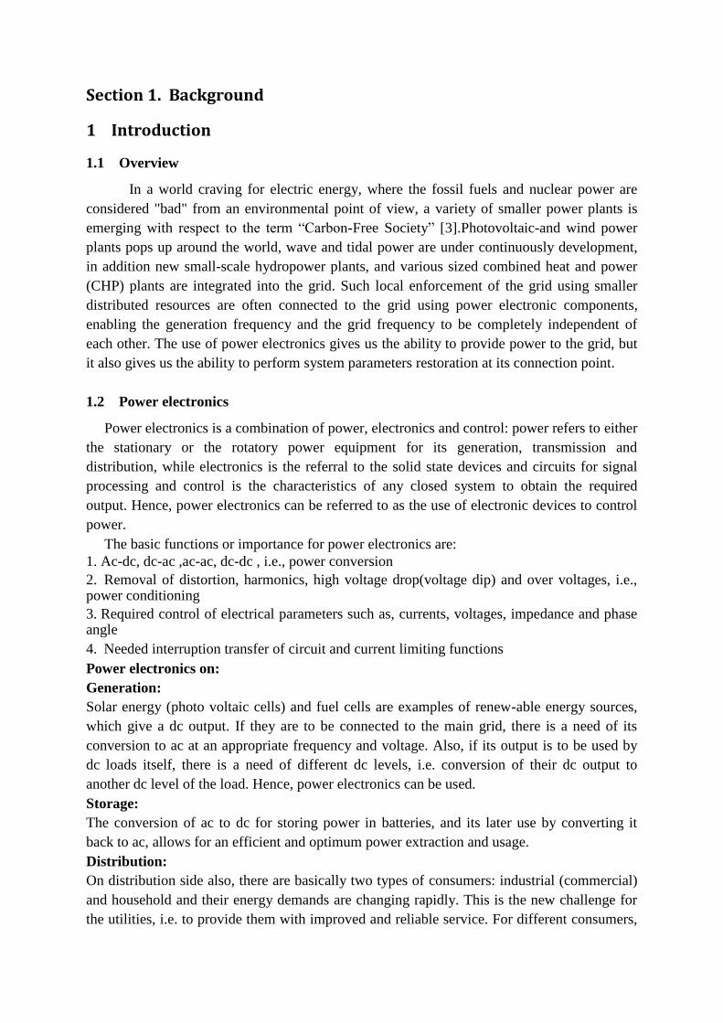
building blocks:
IGBT Three legged Inverter bridge.
Linear load used.

Non-linear load used.
Filtering like this of the dq-values enables splitting the dq-values in fundamental and oscillating
components.
Current and Voltage conversion blocks from the abc -domain to the dqo-domain.
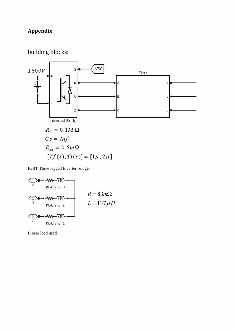
Current conversion blocks from the dqo-domain into the abc-domain, including a PWM at the end
used for controlling the output inverter bridge.
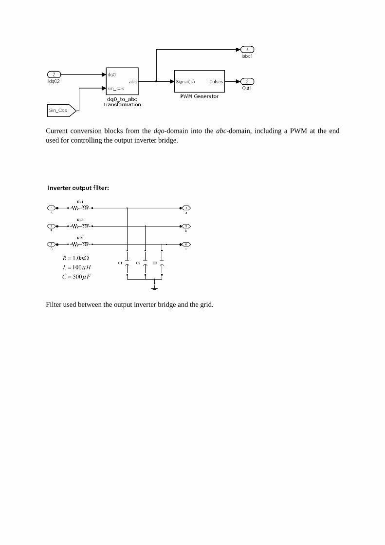
Filter used between the output inverter bridge and the grid.

Current control Scheme: Idref and Iqref is the wanted output given in dq. Vsd1 and Vsq1 is the reference
voltage gotten from the grid.Id1 and Idq is the measures actual generated currents and is compared with
the reference currents. w1 is the grid angle frequency gotten from a PLL.

Voltage control scheme with the previous current control scheme: Vsd and Vsq are measured voltages.
The reference voltage here is Vdref=500V and Vdref which when using a PLL is set to 0. IoD and IoQ are
the measured inverter currents, and it is compared to the internally generated refererence currents,
generated by the voltage control scheme. Id_harmonics and Iq_harmonics were intended for use, when
including harmonic compensation; otherwise they are set to zero.

System Data
vdc = 1600 V, and the switching frequency fs = 12000Hz.
The compensators of the current control scheme have the transfer functions
kd(s) = kq(s) = (s + 15)/ s [Ω]
corresponding to τi = 0.1 ms.
The compensators of the voltage and frequency control loops have the transfer functions
k(s) =(1.66s + 1844)/ s [Ω−1]
kω(s) = 10.0 [V s]