Embed Size (px)
Citation preview

3/2/16 University of Colorado Boulder Aerospace Engineering Sciences 1
Customers
Ellis Langford, Ed Wen
Advisor
Joe Tanner
Actuated Electromagnetic System for Ice Removal
University of Colorado at Boulder

ScheduleBallistic
Pendulum
Flat PlateDeflection
Flat PlateWind Cage
Full Wing
Deflection
Full Wing
Wind CageBudget
University of Colorado Boulder Aerospace Engineering Sciences 2
Overview
3/2/16

ScheduleBallistic
Pendulum
Flat PlateDeflection
Flat PlateWind Cage
Full Wing
Deflection
Full Wing
Wind CageBudget
Problem Statement & Objectives
University of Colorado Boulder Aerospace Engineering Sciences 3
Design, build, and test a small-scale prototype of a
deicing system for the Orion UAV.
Functional Requirements
3/2/16
FR.1 - The full-scale system shall be integrable with the Orion UAV.
FR.2 - The prototype shall remove ice.
FR.3 - The full-scale system shall use less than 4kW-hr to deice
the wing section.
Orion UAV

ScheduleBallistic
Pendulum
Flat PlateDeflection
Flat PlateWind Cage
Full Wing
Deflection
Full Wing
Wind CageBudget
Design Overview
3/2/16 University of Colorado Boulder Aerospace Engineering Sciences 4
Electromagnetic Deicing Mechanism
Deicing Mechanism = Baseline design used for all levels of success
Target DiskMagnetic
Field
Ice

ScheduleBallistic
Pendulum
Flat PlateDeflection
Flat PlateWind Cage
Full Wing
Deflection
Full Wing
Wind CageBudget
Charging Circuit
Functional Block Diagram
University of Colorado Boulder Aerospace Engineering Sciences 5
1000 V Power Supply
Operator (person)
Discharging Circuit
3.5 V Power Supply
3/2/16
Deicing Mechanism
SolenoidTarget
Disk
High Voltage
Line
Low Voltage
Line
Legend
Mechanism
Electrical
Operation
Operator
Control
Force
Interaction
Charge
Discharge
Dump

ScheduleBallistic
Pendulum
Flat PlateDeflection
Flat PlateWind Cage
Full Wing
Deflection
Full Wing
Wind CageBudget
Deicing CircuitDAE11 Wing
Section
SolenoidIce Casting Apparatus
DAE11 Wing Section
Concept of Operations
University of Colorado Boulder Aerospace Engineering Sciences 63/2/16
Ice Testing Occurs in Freezer (−𝟏𝟏𝒐𝑭)
12 12
3
45
678
9
1011
Freezing Time
Purpose of Level 3:• Integration into wing structure-like Orion UAV
• Testing in flight-like wing section and conditions
Test cage with viewing window
Deicing
Circuit
3/8th In thick ice
OFF
Electric Leaf Blower (3)
Test cage with viewing window
Electric Leaf Blower (3)
Deicing
Circuit
Broken Ice
ON

ScheduleBallistic
Pendulum
Flat PlateDeflection
Flat PlateWind Cage
Full Wing
Deflection
Full Wing
Wind CageBudget
Levels of Success
University of Colorado Boulder Aerospace Engineering Sciences 73/2/16
Level of Success
Description Corresponding Tests Level of Success Achieved
when…
1
Deicing
mechanism
integrated with
ballistic pendulum
Ballistic
Pendulum• Ballistic Pendulum Tests Solenoid Force Model verified
2
Deicing
mechanism
integrated with
carbon fiber flat
plate
Flat
Plate
• Deflection tests
• Deicing tests in simulated
flight conditions
ANSYS Model verified.
Ice broken from flat plate
3
Deicing
mechanism
integrated with
carbon fiber full
wing section
Full
Wing
Section
• Deflection tests
• Deicing tests in simulated
flight conditions
Ice broken from wing section in
simulated flight conditions
Deicing Mechanism = Baseline design used for all levels of success
ScheduleBallistic
Pendulum
Flat PlateDeflection
Flat PlateWind Cage
Full Wing
Deflection
Full Wing
Wind CageBudget
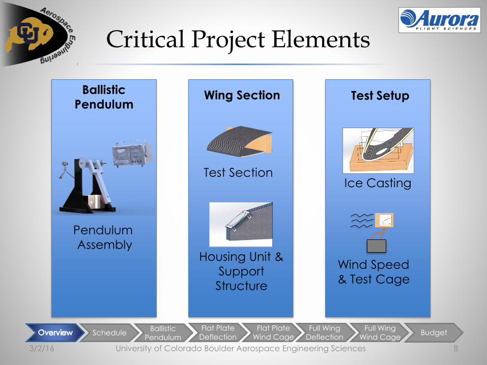
Critical Project Elements
University of Colorado Boulder Aerospace Engineering Sciences 8
Ballistic
Pendulum
Pendulum
Assembly
Wing Section
Test Section
Housing Unit &
Support
Structure
3/2/16
Test Setup
Wind Speed
& Test Cage
Ice Casting

OverviewBallistic
Pendulum
Flat PlateDeflection
Flat PlateWind Cage
Full Wing
Deflection
Full Wing
Wind CageBudget
University of Colorado Boulder Aerospace Engineering Sciences 9
Schedule
3/2/16

OverviewBallistic
Pendulum
Flat PlateDeflection
Flat PlateWind Cage
Full Wing
Deflection
Full Wing
Wind CageBudget
Overall Schedule
University of Colorado Boulder Aerospace Engineering Sciences 103/2/16
Total Testing Margin = 2 Weeks
Total Presentation/Paper Margin = 1.5 Weeks

OverviewBallistic
Pendulum
Flat PlateDeflection
Flat PlateWind Cage
Full Wing
Deflection
Full Wing
Wind CageBudget
Test-Focused Schedule
University of Colorado Boulder Aerospace Engineering Sciences 113/2/16
Week 1 Week 5 Week 10 Week 14
Total Testing Margin = 2 Weeks

Overview ScheduleFlat Plate
DeflectionFlat Plate
Wind CageFull Wing
Deflection
Full Wing
Wind CageBudget
University of Colorado Boulder Aerospace Engineering Sciences 12
Test Readiness
3/2/16
Overview ScheduleFlat Plate
DeflectionFlat Plate
Wind CageFull Wing
Deflection
Full Wing
Wind CageBudget
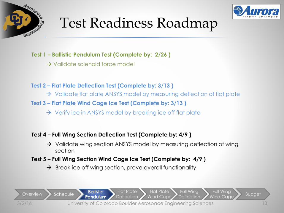
Test Readiness Roadmap
University of Colorado Boulder Aerospace Engineering Sciences 133/2/16
Test 1 – Ballistic Pendulum Test (Complete by: 2/26 )
Validate solenoid force model
Test 2 – Flat Plate Deflection Test (Complete by: 3/13 )
Validate flat plate ANSYS model by measuring deflection of flat plate
Test 3 – Flat Plate Wind Cage Ice Test (Complete by: 3/13 )
Verify ice in ANSYS model by breaking ice off flat plate
Test 4 – Full Wing Section Deflection Test (Complete by: 4/9 )
Validate wing section ANSYS model by measuring deflection of wing section
Test 5 – Full Wing Section Wind Cage Ice Test (Complete by: 4/9 )
Break ice off wing section, prove overall functionality

Overview ScheduleFlat Plate
DeflectionFlat Plate
Wind CageFull Wing
Deflection
Full Wing
Wind CageBudget
Ballistic Pendulum Overview
University of Colorado Boulder Aerospace Engineering Sciences 143/2/16
Purpose Requirements Verified
• Verify solenoid force model• Validate design
• DR.2.1 The deicing mechanism shall be capable of removing 3/8
in thick ice on test section
• DR.3.1 The deicing mechanism shall operate on an incoming 28
V DC voltage line.
• DR.3.2 The full-span system instantaneous power draw shall be at
most 2 kW.Ballistic Pendulum Test Setup
High Speed
Camera
In-House Encoder
Accelerometer
Oscilloscope
2 Methods to Calculate Solenoid Output Force
Measure Calculate
Acceleration(Accelerometer)
Max Angle(In-House Encoder)
Force (via torque,
conservation of energy)
Force (via conservation
Of angular momentum)

Overview ScheduleFlat Plate
DeflectionFlat Plate
Wind CageFull Wing
Deflection
Full Wing
Wind CageBudget
Recall: Solenoid Force Model Derivation
University of Colorado Boulder Aerospace Engineering Sciences 153/2/16
Goal: Determine max impulsive force from solenoid using COMSOL model
d
N
F
Do
Di
F Solenoid
t
Target Disk
Input Parameters• 𝐼 − Current
• 𝑁 − Number of wire loops• 𝐻 − Height• 𝐷 − Diameters• 𝑑 − Gap distance• σ − Electric conductivity• μ − Magnetic permeability
System of Equations
σ𝜕A
𝜕t+ 𝛻 × μ0
−1μr−1𝛻 × A = Je
B = 𝛻 × A
F = 𝜕Ω
T n dS
Maximum Force: 262 N @ 1000 V

Overview ScheduleFlat Plate
DeflectionFlat Plate
Wind CageFull Wing
Deflection
Full Wing
Wind CageBudget
Solenoid Force Model
University of Colorado Boulder Aerospace Engineering Sciences 163/2/16
0
50
100
150
200
250
300
400 500 600 700 800 900 1000 1100
FORCE VS. VOLTAGECopper Solenoid Parameter Value
Outer diameter 3.000 in
Inner diameter 0.039 in
Height 0.190 in
Wire thickness 0.030 in
Average gap between wire loops
0.007 in
Number of turns 36
Copper Target DiskParameter
Value
Gap distance 0.078 in
Disk thickness 0.078 in
Disk Diameter 4.000 in
836 V
180 N
(40.5 lb)

Overview ScheduleFlat Plate
DeflectionFlat Plate
Wind CageFull Wing
Deflection
Full Wing
Wind CageBudget
40
Solenoid Force Model & Predicted Results
University of Colorado Boulder Aerospace Engineering Sciences 173/2/16
Max Angle vs. Force
Accelerometer Sensitivity: 1.0 mV/g
Force Uncertainty: + 2.4 lb In-House Encoder Uncertainty: 0.1o
Force Uncertainty: + 0.47 lb
Force vs. Measured Voltage
= Freq (40.5 lb) to break ice off full wing section
90
80
50
60
90
30
208
70
Ca
lcu
late
d F
orc
e (
lb)
6 10 12 142 40

Overview ScheduleBallistic
Pendulum
Flat PlateWind Cage
Full Wing
Deflection
Full Wing
Wind CageBudget
Flat PlateDeflection Test Overview
University of Colorado Boulder Aerospace Engineering Sciences 183/2/16
Purpose Requirements Verified
• Verify ANSYS deflection model with measured deflection
• DR.1.3 Operation of the deicing mechanism shall not damage or degrade the structural integrity of
the wing• DR.2.1 The deicing mechanism shall be capable of
removing 3/8 in thick ice on test section
Testing Location: Thorlabs
Flat Plate Deflection Test Setup
Flat Plate Deflection Testing (Complete by: )
Measure Calculate
Distance traveled by
laser (D)
Deflection of
flat plate
(via geometry)
D
Θd
2𝜑
𝜑
𝐷1 𝐷2
𝐿
Cross-sectional view of carbon fiber flat plater
Initial Laser Beam

Overview ScheduleBallistic
Pendulum
Flat PlateWind Cage
Full Wing
Deflection
Full Wing
Wind CageBudget
Recall: Flat Plate Analysis & ANSYS Model
University of Colorado Boulder Aerospace Engineering Sciences 193/2/16
a = 24 in
b = 20 in
Force, W, applied over circular region
𝑦𝑚𝑎𝑥 =𝛼𝑊𝑏2
𝐸𝑡3𝛼 ≈ 0.0706,
(appr. from a/b = 1.2)
Back of the Envelope Assumptions• Thickness = uniform, 0.09 in carbon fiber with 3/8 in
thick honeycomb• Force acts on center of plate• Fixed Boundary Conditions on all sides
𝒚𝒎𝒂𝒙,𝒄𝒂𝒍𝒄 = 𝟎. 𝟎𝟎𝟖 𝒊𝒏
𝒚𝒎𝒂𝒙,𝑨𝑵𝑺𝒀𝑺 = 𝟎. 𝟎𝟓 𝒊𝒏
• Flat Plate ANSYS Model- calculates deflection of carbon fiber, force
necessary to break ice thickness
• To Check model: Back of the Envelope Deflection for Flat Plate
- from Roark’s Formulas
• Full model validation to occur with deflection and ice break testing

Overview ScheduleBallistic
Pendulum
Flat PlateWind Cage
Full Wing
Deflection
Full Wing
Wind CageBudget
Flat Plate ANSYS Deflection Model
University of Colorado Boulder Aerospace Engineering Sciences 203/2/16
(inches)

Overview ScheduleBallistic
Pendulum
Flat PlateWind Cage
Full Wing
Deflection
Full Wing
Wind CageBudget
Flat Plate Deflection Expected Results from ANSYS
University of Colorado Boulder Aerospace Engineering Sciences 213/2/16
Expected Error in Measurements
Flat Plate Deflection Model
0
100
200
300
400
500
600
0 20 40 60 80
Ma
x S
tre
ss in
Ic
e (
psi
)
Force (lb)
Maximum Stress in Ice vs Force
0
0.02
0.04
0.06
0.08
0.1
0 20 40 60 80
De
fle
ctio
n (
in)
Force (lb)
Deflection of Carbon Fiber vs
Force with Ice
* Force required to break 3/8 in ice on flat plate = ~45 lb 0.057 in deflection of carbon fiber w/ ice
*
Without ice on plate (no ice when measuring in Thorlabs)
Predicted Deflection = 0.230 in + 0.005 inch

Overview ScheduleBallistic
Pendulum
Flat PlateDeflection
Full Wing
Deflection
Full Wing
Wind CageBudget
Flat Plate Wind Cage Test Overview
University of Colorado Boulder Aerospace Engineering Sciences 223/2/16
Purpose Requirements Verified
• Validate flat plate ANSYS model with force & ice breaking
• Test in representative flight conditions
• DR.2.1 The deicing mechanism shall be capable of removing 3/8 in thick ice on test section
• SPEC.2.1 The deicing mechanism shall remove ice… with wind speed = 65 knots.
Flat Plate Wind Cage Test Setup
Flat plate setup
Leaf blower setup
Measure Calculate
Distance traveled by
laser, D(with calipers)
Deflection of
flat plate
(via geometry)
Testing Location: INSTAAR Walk-In Freezer (-11oF)
Flat Plate Wind Cage Testing (Complete by: 3/13)

Overview ScheduleBallistic
Pendulum
Flat PlateDeflection
Full Wing
Deflection
Full Wing
Wind CageBudget
Flat Plate Wind Cage Expected/Actual Results
University of Colorado Boulder Aerospace Engineering Sciences 233/2/16
3 leaf blowers simulation: each leaf blower located 1 ft from leading edge
CFD Assumptions• Turbulent and Laminar flow
• Adiabatic Walls
• 1 micro-inch wall roughness
Data from Wind Tunnel Measurements
(12 in from outlet)
• At outlets: 68 knots
• ½ - way between outlets: 7 knots
• ¼ - way between outlets: 27 knots
* Distance between outlet centers = 9 in * Distance between outlet edges = 6 in * Anemometer diameter = 2.5 in

Level 2
TestingOverview Schedule
Ballistic Pendulum
Flat PlateDeflection
Flat PlateWind Cage
Full Wing
Wind CageBudget
Full Wing Section Deflection Test Overview
University of Colorado Boulder Aerospace Engineering Sciences 243/2/16
Purpose Requirements Verified
• Verify ANSYS deflection model• Laser trials complete
before level 3 testing
• DR.1.3 …deicing mechanism shall not damage or degrade the structural integrity of the wing
• DR.2.1 The deicing mechanism shall be capable of removing 3/8 in thick ice on test section
Full Wing Section Test Setup
Measure Calculate
Distance traveled
by laser, D
Deflection of
flat plate
(via geometry)
Testing Location: Thorlabs
D
Θd
2𝜑
𝜑
𝐷1 𝐷2
𝐿
Cross-sectional view of carbon fiber flat plater
Initial Laser Beam
Full Wing Section Deflection Testing

Overview ScheduleBallistic
Pendulum
Flat PlateDeflection
Full Wing
Deflection
Full Wing
Wind CageBudget
Full Wing Section ANSYS Stress Model
University of Colorado Boulder Aerospace Engineering Sciences 253/2/16
(inches)[psi]
Level 2
TestingOverview Schedule
Ballistic Pendulum
Flat PlateDeflection
Flat PlateWind Cage
Full Wing
Wind CageBudget
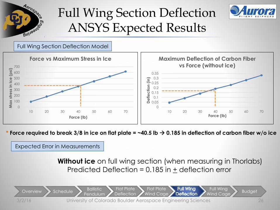
Full Wing Section DeflectionANSYS Expected Results
University of Colorado Boulder Aerospace Engineering Sciences 263/2/16
Full Wing Section Deflection Model
Expected Error in Measurements
0
0.05
0.1
0.15
0.2
0.25
0.3
0.35
10 20 30 40 50 60 70
De
fle
ctio
n (
in)
Force (lb)
Maximum Deflection of Carbon Fiber
vs Force (without ice)
0
100
200
300
400
500
600
700
10 20 30 40 50 60 70
Ma
x s
tre
ss in
Ic
e (
psi
)
Force (lb)
Force vs Maximum Stress in Ice
* Force required to break 3/8 in ice on flat plate = ~40.5 lb 0.185 in deflection of carbon fiber w/o ice
Without ice on full wing section (when measuring in Thorlabs)
Predicted Deflection = 0.185 in + deflection error

Level 2
TestingOverview Schedule
Ballistic Pendulum
Flat PlateDeflection
Flat PlateWind Cage
Full WingDeflection
Budget
Full Wing SectionWind Cage Test Overview
University of Colorado Boulder Aerospace Engineering Sciences 273/2/16
Purpose Requirements Verified
• Gather data on ice crack propagation
• Test in representative flight conditions
• DR.2.1 The deicing mechanism shall be capable of removing 3/8 in thick ice on test section
• SPEC.2.1 The deicing mechanism shall remove ice… with wind speed = 65 knots.
Full Wing Section Wind Cage Test Setup
Test Location: INSTAAR walk-in freezer (-11oF)
Leaf blower setup
Full Wing Section Setup Measure Calculate
Distance traveled by
laser, D(with calipers)
Deflection of
flat plate
(via geometry)
Full Wing Section Deflection Testing (Complete by: 4/9)
Level 2
TestingOverview Schedule
Ballistic Pendulum
Flat PlateDeflection
Flat PlateWind Cage
Full WingDeflection
Budget
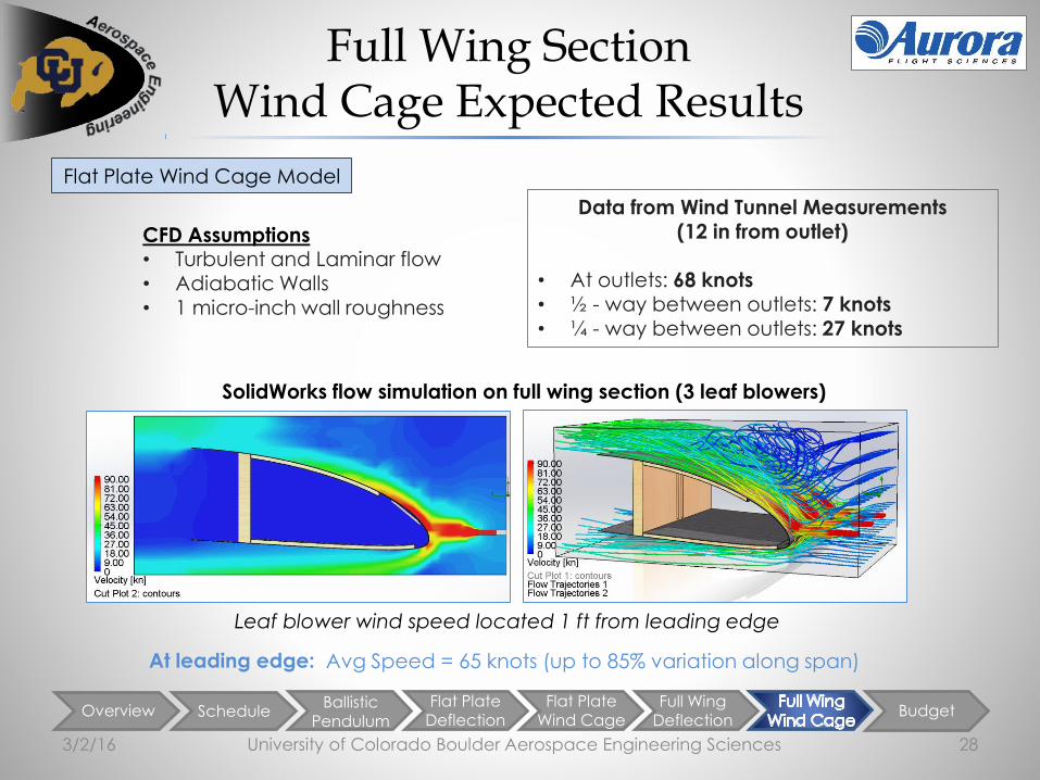
Full Wing SectionWind Cage Expected Results
University of Colorado Boulder Aerospace Engineering Sciences 283/2/16
Flat Plate Wind Cage Model
SolidWorks flow simulation on full wing section (3 leaf blowers)
At leading edge: Avg Speed = 65 knots (up to 85% variation along span)
Leaf blower wind speed located 1 ft from leading edge
CFD Assumptions• Turbulent and Laminar flow• Adiabatic Walls• 1 micro-inch wall roughness
Data from Wind Tunnel Measurements (12 in from outlet)
• At outlets: 68 knots• ½ - way between outlets: 7 knots• ¼ - way between outlets: 27 knots

Overview ScheduleBallistic
Pendulum
Flat PlateDeflection
Flat PlateWind Cage
Full WingDeflection
Full Wing
Wind Cage
University of Colorado Boulder Aerospace Engineering Sciences 29
Budget
3/2/16

Level 1
Testing
Level 2
TestingLevel 3
TestingOverview Schedule
Ballistic Pendulum
Flat PlateDeflection
Flat PlateWind Cage
Full WingDeflection
Full Wing
Wind Cage
Budget Status
University of Colorado Boulder Aerospace Engineering Sciences 303/2/16
0
500
1000
1500
2000
2500
Electronics Wing Test
Section
Dynamic
Testing
Ice Casting
Trough
Management
Purchased Future Purchases
Future Expenses:
Electronics:
Capacitors, Micro-
Controller, Thyristors, Pillow
Bearings
Wing Test Section:
Mold Release, Vacuum
Bags, Sealant Tape, Curing
Platform
Management:
Symposium Poster, Printing,
AIAA Conference
Aerospace Department:
$5,000
EEF*:
$2,215
*To be Approved
Total Project Cost:
$7,215

3/2/16 University of Colorado Boulder Aerospace Engineering Sciences 31
Questions?

ScheduleBallistic
Pendulum
Flat PlateDeflection
Flat PlateWind Cage
Full Wing
Deflection
Full Wing
Wind CageBudget
Requirements – FR1
University of Colorado Boulder Aerospace Engineering Sciences 323/2/16
FR.1 The full-span system shall be integrable with the Orion UAV.
DR.1.2 The deicing mechanism shall be integrable with a wing in the shape of the DAE11 airfoil.
SPEC.1.2.1 The test section chord length shall be 72 in (6 ft).
DR.1.2.1 The components of the deicing mechanism internal to the wing test section
shall fit between the leading edge (0 in.) and half-chord line (36 in.) in the chord-wisedirection.
DR.1.3 The installation of the deicing mechanism shall not damage or degrade the structuralintegrity of the wing.
DR.1.4 The operation of the deicing mechanism shall not damage or degrade thestructural integrity of the wing over a lifetime of 150 hours.

ScheduleBallistic
Pendulum
Flat PlateDeflection
Flat PlateWind Cage
Full Wing
Deflection
Full Wing
Wind CageBudget
Requirements – FR2
University of Colorado Boulder Aerospace Engineering Sciences 333/2/16
FR.2 The deicing mechanism shall remove ice.
SPEC.2.1 The deicing mechanism shall remove ice in an environment with wind speed = 65 knots.
DR.2.1 The deicing mechanism shall be capable of removing 3/8 in thick ice on test section.
SPEC.2.1.1 The ice shall cover the test section from the leading edge to 7% of the chord(7.2 in) as measured chord-wise from the leading edge on the upper airfoil surface andto 2% of the chord (1.7 in) as measured chord-wise from the leading edge on the lowerairfoil surface
DR.2.2 The deicing mechanism shall be capable of removing ice at any time
during a five-daycontinuous flight.
DR.2.3 The maximum allowable thickness of ice remaining at any point along the surface of thetest section after activating the prototype shall be 0.1 in.

ScheduleBallistic
Pendulum
Flat PlateDeflection
Flat PlateWind Cage
Full Wing
Deflection
Full Wing
Wind CageBudget
Requirements – FR3
University of Colorado Boulder Aerospace Engineering Sciences 343/2/16
FR.3 The full-span system shall use less than 4kW-hr of energy to deice the wing section.
DR.3.1 The deicing mechanism shall operate on an incoming 28 V DC voltage line.
DR.3.2 The full-span system instantaneous power draw shall be at most 2 kW.

OverviewBallistic
Pendulum
Flat PlateDeflection
Flat PlateWind Cage
Full Wing
Deflection
Full Wing
Wind CageBudget
University of Colorado Boulder Aerospace Engineering Sciences 35
Schedule Backup
3/2/16

OverviewBallistic
Pendulum
Flat PlateDeflection
Flat PlateWind Cage
Full Wing
Deflection
Full Wing
Wind CageBudget
Work Plan MSR
University of Colorado Boulder Aerospace Engineering Sciences 363/2/16
Spring 2016
Week 10Week 5Week 1 Week 15
= Test Setup
= Wing Section
= Ballistic Pendulum
= Testing
= Spring Break
= Milestone
= Margin

Overview ScheduleFlat Plate
DeflectionFlat Plate
Wind CageFull Wing
Deflection
Full Wing
Wind CageBudget
University of Colorado Boulder Aerospace Engineering Sciences 37
Ballistic Pendulum Backup
3/2/16

Overview ScheduleFlat Plate
DeflectionFlat Plate
Wind CageFull Wing
Deflection
Full Wing
Wind CageBudget
Force Model Verification
University of Colorado Boulder Aerospace Engineering Sciences 383/2/16

Overview ScheduleFlat Plate
DeflectionFlat Plate
Wind CageFull Wing
Deflection
Full Wing
Wind CageBudget
Force Model Verification
University of Colorado Boulder Aerospace Engineering Sciences 393/2/16
Finer
Extra Fine
Overview ScheduleFlat Plate
DeflectionFlat Plate
Wind CageFull Wing
Deflection
Full Wing
Wind CageBudget
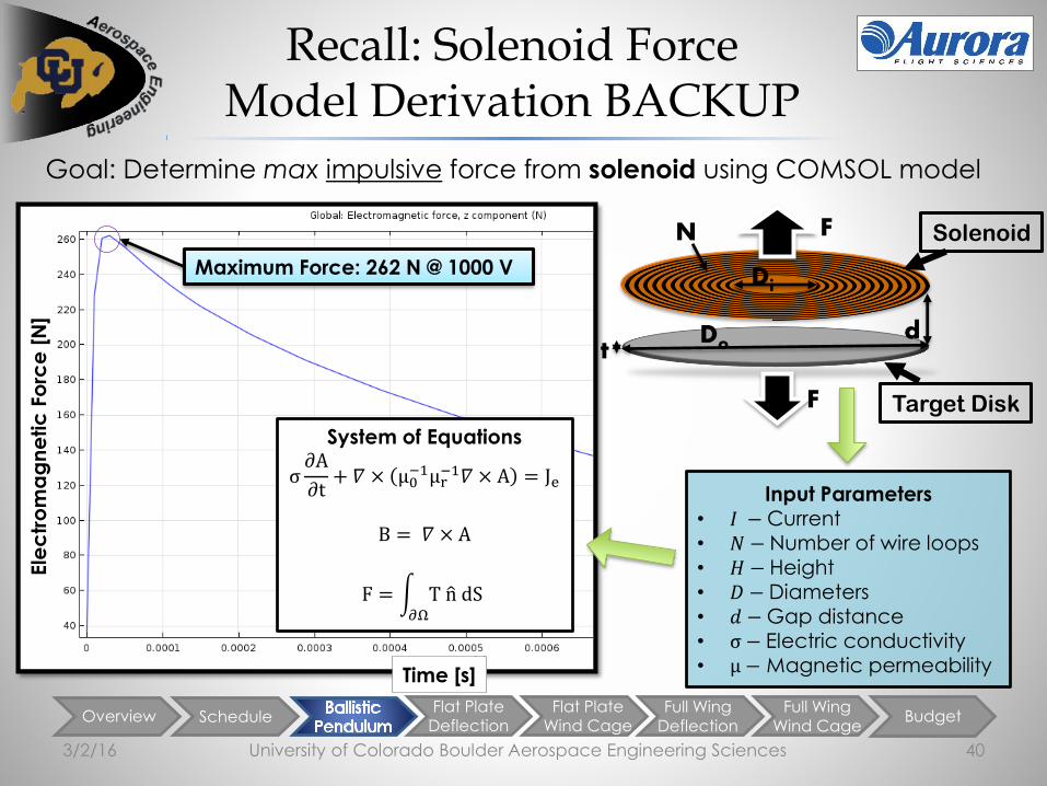
Recall: Solenoid Force Model Derivation BACKUP
University of Colorado Boulder Aerospace Engineering Sciences 403/2/16
Goal: Determine max impulsive force from solenoid using COMSOL model
d
N
F
Do
Di
F Solenoid
t
Target Disk
Input Parameters• 𝐼 − Current • 𝑁 − Number of wire loops
• 𝐻 − Height• 𝐷 − Diameters• 𝑑 − Gap distance• σ − Electric conductivity• μ − Magnetic permeability
System of Equations
σ𝜕A
𝜕t+ 𝛻 × μ0
−1μr−1𝛻 × A = Je
B = 𝛻 × A
F = 𝜕Ω
T n dS
Ele
ctr
om
ag
ne
tic
Fo
rce
[N
]
Time [s]
Maximum Force: 262 N @ 1000 V

Overview ScheduleFlat Plate
DeflectionFlat Plate
Wind CageFull Wing
Deflection
Full Wing
Wind CageBudget
COMSOL Model Backup
University of Colorado Boulder Aerospace Engineering Sciences 413/2/16
Magnetic field lines from COMSOL model

Overview ScheduleFlat Plate
DeflectionFlat Plate
Wind CageFull Wing
Deflection
Full Wing
Wind CageBudget
Ballistic Pendulum Energy Conservation Method
University of Colorado Boulder Aerospace Engineering Sciences 423/2/16
Goal: Determine impulsive force from energy conservation
𝑭 = 𝒎𝒂 = 𝒎𝒗
𝚫𝒕=
𝒎 𝟔𝒈𝑳𝒄𝒎 𝟏 − 𝒄𝒐𝒔𝜽
𝑰𝑹 𝒍𝒏
𝑽𝑽𝟎
Constants Variable
Mass m
Gravity g
Discharged Voltage V
Initial Voltage Vo
Resistance R
Inductance I
𝛉 − 𝐌𝐞𝐚𝐬𝐮𝐫𝐞𝐝 𝐕𝐚𝐥𝐮𝐞

University of Colorado Boulder Aerospace Engineering Sciences 43
Accelerometer Backup
3/2/16
Solenoid in Test
Housing
Pendulum Arm
Rotation Point
Accelerometer
Target Disk
r
Use torque:
𝜏 = 𝑟 ∗ 𝐹 ∗ 𝑠𝑖𝑛𝜃 = 𝐼 ∗ 𝛼
𝐹 =𝐼 ∗ 𝛼
𝑟=
𝐼 ∗ 𝑎𝑡𝑎𝑛
𝑟2
Assume:
- Max force applied at first instant
- Force applied exactly
perpendicular to pendulum arm
- I (full pendulum arm) ≈ I
(pendulum arm from top to
accelerometer)
- Negligible friction in bearings
𝑟 𝐹

Overview ScheduleFlat Plate
DeflectionFlat Plate
Wind CageFull Wing
Deflection
Full Wing
Wind CageBudget
Acceleration: Impact Model
University of Colorado Boulder Aerospace Engineering Sciences 443/2/16
𝐹 = 𝑡1𝑡2 𝑎 𝑑𝑡
∆𝑡ℎℎ𝑚𝐶 𝐷𝐵𝐶
2 + ℎ2 +1
4𝑙2𝑚𝐵 + 𝐼𝐵 + 𝐼𝑐
CBA
𝐷𝐵𝐶
ℎ
1
2𝑙
𝐻𝐴′ = ℎ𝑚𝐴𝑉𝐴
′ + 𝐼𝐴𝜔𝐴′
𝐻𝐵′ =
1
2𝑙𝑚𝐵𝑉𝐵
′ + 𝐼𝐵𝜔𝐵′
𝐻𝐶′ = ℎ𝑚𝐶𝑉𝐶
′ + 𝐼𝐶𝜔𝐶′
𝜔𝐴′ = 𝜔𝐵
′ = 𝜔𝑐′

Overview ScheduleFlat Plate
DeflectionFlat Plate
Wind CageFull Wing
Deflection
Full Wing
Wind CageBudget
Solenoid Force Model & Predicted Results
University of Colorado Boulder Aerospace Engineering Sciences 453/2/16
Max Angle vs. ForceAcceleration vs. Force
Design 50o at
58 lb of force
Design 20 gs at 58
lb of force
Acceleration & Max Angle Models

Overview ScheduleFlat Plate
DeflectionFlat Plate
Wind CageFull Wing
Deflection
Full Wing
Wind CageBudget
University of Colorado Boulder Aerospace Engineering Sciences 46
Deflection Backup
3/2/16

Overview ScheduleBallistic
Pendulum
Flat PlateDeflection
Full Wing
Deflection
Full Wing
Wind CageBudget
Deflection Measurement
University of Colorado Boulder Aerospace Engineering Sciences 473/2/16
D
Θd
2𝜑
𝜑
𝐷1 𝐷2
r
𝑑 = 𝑟 sin(𝜑)
𝑘=1
𝑃
sin[(2𝑘 − 1)𝜑]
𝐿
=1
2tan(𝜃)𝐷 −
2𝐿
2cos2 𝜃 cot 2𝜑 + sin 2𝜃

Overview ScheduleBallistic
Pendulum
Flat PlateWind Cage
Full Wing
Deflection
Full Wing
Wind CageBudget
Deflection Uncertainty
University of Colorado Boulder Aerospace Engineering Sciences 483/2/16
D
Θd
2𝜑
𝜑𝐷1 𝐷2
𝐿
r
Initial
Laser
Beam
Overview ScheduleBallistic
Pendulum
Flat PlateWind Cage
Full Wing
Deflection
Full Wing
Wind CageBudget
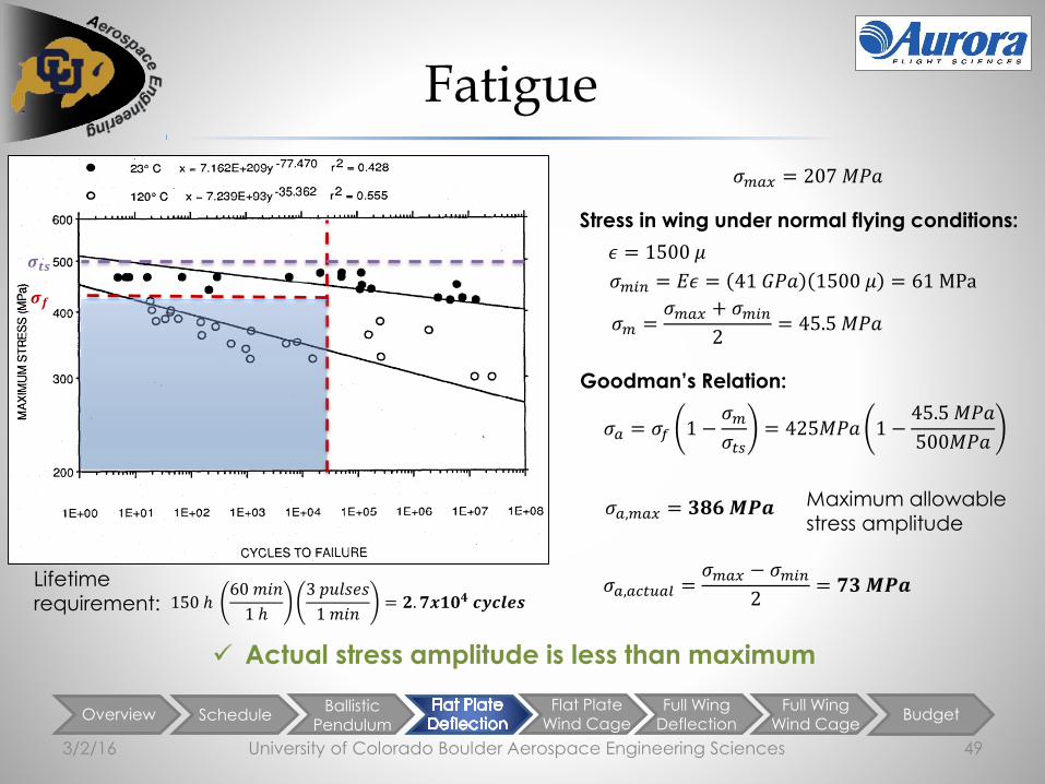
Fatigue
University of Colorado Boulder Aerospace Engineering Sciences 493/2/16
150 ℎ60 𝑚𝑖𝑛
1 ℎ
3 𝑝𝑢𝑙𝑠𝑒𝑠
1 𝑚𝑖𝑛= 𝟐. 𝟕𝒙𝟏𝟎𝟒 𝒄𝒚𝒄𝒍𝒆𝒔
Goodman’s Relation:
𝜎𝑎 = 𝜎𝑓 1 −𝜎𝑚
𝜎𝑡𝑠= 425𝑀𝑃𝑎 1 −
45.5 𝑀𝑃𝑎
500𝑀𝑃𝑎
𝜎𝑎,𝑚𝑎𝑥 = 𝟑𝟖𝟔 𝑴𝑷𝒂
𝜖 = 1500 𝜇
𝜎𝑚𝑖𝑛 = 𝐸𝜖 = 41 𝐺𝑃𝑎 1500 𝜇 = 61 MPa
Stress in wing under normal flying conditions:
Maximum allowable stress amplitude
𝜎𝑚 =𝜎𝑚𝑎𝑥 + 𝜎𝑚𝑖𝑛
2= 45.5 𝑀𝑃𝑎
𝜎𝑚𝑎𝑥 = 207 𝑀𝑃𝑎
𝜎𝑎,𝑎𝑐𝑡𝑢𝑎𝑙 =𝜎𝑚𝑎𝑥 − 𝜎𝑚𝑖𝑛
2= 𝟕𝟑 𝑴𝑷𝒂
Actual stress amplitude is less than maximum
Lifetime requirement:
𝝈𝒕𝒔
𝝈𝒇

Overview ScheduleFlat Plate
DeflectionFlat Plate
Wind CageFull Wing
Deflection
Full Wing
Wind CageBudget
University of Colorado Boulder Aerospace Engineering Sciences 50
Full Span Analysis Backup
3/2/16

Overview ScheduleFlat Plate
DeflectionFlat Plate
Wind CageFull Wing
Deflection
Full Wing
Wind CageBudget
Power Consumption
University of Colorado Boulder Aerospace Engineering Sciences 513/2/16
𝑇𝑜𝑡𝑎𝑙 𝐸𝑛𝑒𝑟𝑔𝑦 = # 𝑜𝑓 𝑆𝑜𝑙𝑒𝑛𝑜𝑖𝑑𝑠 ∗ # 𝑜𝑓 𝐼𝑚𝑝𝑢𝑙𝑠𝑒𝑠 ∗𝐸𝑛𝑒𝑟𝑔𝑦
𝐼𝑚𝑝𝑢𝑙𝑠𝑒
𝑇𝑜𝑡𝑎𝑙 𝐸𝑛𝑒𝑟𝑔𝑦 = 76 𝑆𝑜𝑙𝑒𝑛𝑜𝑖𝑑𝑠 ∗ 3 𝐼𝑚𝑝𝑢𝑙𝑠𝑒𝑠 ∗ 500𝐽𝑜𝑢𝑙𝑒𝑠
𝐼𝑚𝑝𝑢𝑙𝑠𝑒
Total Energy = 114,000 Joules
Power = 2 kW for 1 min or 100 W for 17 min
Power required to run mechanism will not exceed 2kW

Level 2
TestingOverview Schedule
Ballistic Pendulum
Flat PlateDeflection
Flat PlateWind Cage
Full Wing
Wind CageBudget
Full-span Backup
3/2/16 University of Colorado Boulder Aerospace Engineering Sciences 52

Level 2
TestingOverview Schedule
Ballistic Pendulum
Flat PlateDeflection
Flat PlateWind Cage
Full Wing
Wind CageBudget
Full-span Weight Budget
3/2/16 University of Colorado Boulder Aerospace Engineering Sciences 53
Item Weight (lb)
Solenoids + Target Plates (76) 38.3
Housings (76) 69.3
Capacitors + Mounting (10) 27.2
Wire + Mounting 30.7
Voltage Converters 55.0
Total 221 lb

Overview ScheduleFlat Plate
DeflectionFlat Plate
Wind CageFull Wing
Deflection
Full Wing
Wind CageBudget
University of Colorado Boulder Aerospace Engineering Sciences 54
Manufacturing Backup
3/2/16

Overview ScheduleBallistic
Pendulum
Flat PlateDeflection
Full Wing
Deflection
Full Wing
Wind CageBudget
Wing Section Backup –Housing Unit
3/2/16 University of Colorado Boulder Aerospace Engineering Sciences 55
* All units in inches Tolerance = 0.01 inches
Housing Unit SolidWorks Designs

Overview ScheduleBallistic
Pendulum
Flat PlateDeflection
Full Wing
Deflection
Full Wing
Wind CageBudget
Wing Section Backup –Support Structure
3/2/16 University of Colorado Boulder Aerospace Engineering Sciences 56
* All units in inches Tolerance = 0.01 inches
Support Structure SolidWorks Designs

Overview ScheduleBallistic
Pendulum
Flat PlateDeflection
Full Wing
Deflection
Full Wing
Wind CageBudget
Test Cage Backup
3/2/16 University of Colorado Boulder Aerospace Engineering Sciences 57
Test Cage (all units in inches)

Overview ScheduleBallistic
Pendulum
Flat PlateDeflection
Full Wing
Deflection
Full Wing
Wind CageBudget
Wing Section Rib Backup
3/2/16 University of Colorado Boulder Aerospace Engineering Sciences 58
Dragon Plate Rib
(Carbon Fiber plates with foam core)

Overview ScheduleFlat Plate
DeflectionFlat Plate
Wind CageFull Wing
Deflection
Full Wing
Wind CageBudget
University of Colorado Boulder Aerospace Engineering Sciences 59
Test Setup Backup
3/2/16

Level 2
TestingOverview Schedule
Ballistic Pendulum
Flat PlateDeflection
Flat PlateWind Cage
Full Wing
Wind CageBudget
Test Setup Backup
3/2/16 University of Colorado Boulder Aerospace Engineering Sciences 60
Leaf Blower Simulation 3 Leaf blowers simulated in test cage with exit velocity = 250 knots

Level 2
TestingOverview Schedule
Ballistic Pendulum
Flat PlateDeflection
Flat PlateWind Cage
Full Wing
Wind CageBudget
Flow Simulation Details
University of Colorado Boulder Aerospace Engineering Sciences 613/2/16
Flow Sim Boundary Conditions:-at leaf blower outlets: 250 knots
-at test cage inlet/outlet: environmental pressure (12.2 psi)
Flow Sim Initial Conditions:
-Environmental pressure (12.2 psi)
-Environmental Temp: -11 F
-Turbulence intensity: 2%
-Turbulence length: 0.2 in
-Velocity: 0 kn
Flow Sim Misc Parameters:
-Turbulent and Laminar flow
-Adiabatic Walls
-1 microinch wall roughness
Wind Tunnel Measurements (12 in from outlet):
-at outlets: 68 knots
-halfway between outlets: 7 knots
-quarter way between outlets: 27 knots
(distance between outlet centers was 9 in;
distance between outlet edges was 6 in; anemometer diameter is 2.5 in)

Level 2
TestingOverview Schedule
Ballistic Pendulum
Flat PlateDeflection
Flat PlateWind Cage
Full Wing
Wind CageBudget
Wing Section Wind Cage Backup
University of Colorado Boulder Aerospace Engineering Sciences 623/2/16

Level 2
TestingOverview Schedule
Ballistic Pendulum
Flat PlateDeflection
Flat PlateWind Cage
Full Wing
Wind CageBudget
Leaf Blower Stand
University of Colorado Boulder Aerospace Engineering Sciences 633/2/16

Level 1
Testing
Level 2
TestingLevel 3
TestingOverview Schedule
Ballistic Pendulum
Flat PlateDeflection
Flat PlateWind Cage
Full WingDeflection
Full Wing
Wind Cage
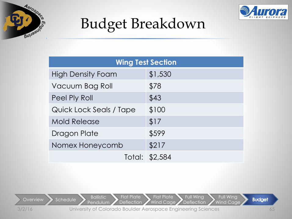
Budget Breakdown
University of Colorado Boulder Aerospace Engineering Sciences 643/2/16
Electrical Purchases
Ribbon Wire $400
Diode damper, Capacitors,
Resistors, Switch
$525
Nylon for Pendulum Arm $147
Total: $1,072
Ice Casting Apparatus
Low Density Poly $15
Acrylic $90
Aluminum Blocks $63
Total: $168
Level 1
Testing
Level 2
TestingLevel 3
TestingOverview Schedule
Ballistic Pendulum
Flat PlateDeflection
Flat PlateWind Cage
Full WingDeflection
Full Wing
Wind Cage
Budget Breakdown
University of Colorado Boulder Aerospace Engineering Sciences 653/2/16
Wing Test Section
High Density Foam $1,530
Vacuum Bag Roll $78
Peel Ply Roll $43
Quick Lock Seals / Tape $100
Mold Release $17
Dragon Plate $599
Nomex Honeycomb $217
Total: $2,584

Level 1
Testing
Level 2
TestingLevel 3
TestingOverview Schedule
Ballistic Pendulum
Flat PlateDeflection
Flat PlateWind Cage
Full WingDeflection
Full Wing
Wind Cage
Budget Breakdown
University of Colorado Boulder Aerospace Engineering Sciences 663/2/16
Dynamic Testing
Fan $706
Leaf Blowers $150
Wood / Home Depot $120
Total: $976


![ELECTROMAGNETIC-ACTUATED CLUTCHES AND ......ELECTROMAGNETIC-ACTUATED CLUTCHES AND BRAKES Product Lineup P.300 P.304 P.306 P.308 CBW CMW 121- -10G122 Clutch/brake torque [N·m] 5 〜](https://img.pdfslide.net/doc/110x75/5ffb1037c8e50875111bc0eb/electromagnetic-actuated-clutches-and-electromagnetic-actuated-clutches.jpg)