Embed Size (px)
Citation preview
AD-A284 918
Fuel Line Study
9ELECTE
August 1994
* DOT/FANICT-TN941 14
DOcumtion file atthTehiaC ay
t~')094-30664
U.S. Departmnent of TransportationFedoeralAviation Admlnletratlon t ~. .. L ~-.Technical CenterAtlantic City International Airport, NJ 08405
q~m*)94 9 23 065

NOTICE
This document is disseminated under the sponsorshipof the U. S. Department of Transportation in the interestof information exchange. The United States Governmentassumes no liability for the contents or use thereof.
The United.States Government does not endorse productsor manufacturers. Trade or manufacturers' naes appearherein solely because they are considered essential to theobjective of this report.
Technical Report Documentation Page
|. Rort No. 2. Government Accession No. 3. Recipient's Catalog No.
4. Title end Subtitle S. Report Dote
July 1994FUEL LIU FTEING TEEICAL NOTM 6. Performing Orgeneiation Code
a. Performing Orgenization Report No.7. Authoers)
Stephanie Monaco9. Performing Organizetion Noam and Address 10. Work Unit No. (TRAIS)
Atlantic Science and Technology Corp.1413 Cantillion Blvd., suite 200 11. Centract or Grant No.
Mays Landing, NJ 08330 DTFAO3-92-P-0188413. Type of Report end Period Covered
12. Sponsoring Agency Nome and Address Technical NoteU.S. Department of Transportation Sept. 1992 - July 1994Federal Aviation AdministrationTlechnical Center 14. Sponsoring Agency CodeAtlantic City international Airport, NJ 08405 ACD-210
IS. Suppleaentery Notes
FAA Program Manager: Gary Frizngs
16. Abstract
This report is part of an ongoing effort directed tovard the complete crash-resistant fuel system (CRFS). It reviews, ealuates, and summarizes thecurrent use of fittings and fuel lines in transport category aircraft. Inaddition, aailable aircraft crash data is analyzed and several conclusions arepresented regarding fuel/line fitting technology.
17. Key Words 18. Distribution Statement
Fuel Line Document is on file at the Technical
Fitting Center Library, Atlantic CityPbst-crash Fire International Airport, New Jersey 08405Crash-Besistent Fuel System
19. Security Clossil. (of this repowt) 20. Security Clessif. (of this page) 21. No. of Pages 22. Price
Unclassified Unclassified 42
Form DOT F 1700.7 (8-72) Reproduction of completed page authorized

TABLE OF CONTENTS
EXECUTIVE SUMMARY ............................................ v
1. INTRODUCTION ................................................ I
1.1 Purpose ................................................. 21.2 Approach . ............................................... 2
2. RESEARCH SUMMARY .......................................... 4
2.1 General nfornation ........................................ 42.2 Related Documentation ....................................... 52.3 National Transportation Safety Board. ............................ 8
2.3.1 NTSB Aircraft Accident Briefs ........................... 92.3.2 NTSB "Annual Review of Aircraft Accident Data" ............. 92.3.3 NTSB Aircraft Accident Reports ......................... 92.3.4 Flight Safety Foundation - Flight Safety Digest ............... 9
2.4 Aircraft Manufacturers ....................................... 10
2.4.1 Boeing 747 ........................................ 102.4.2 McDonnell Douglas DC-i0-40 ........................... 112.4.3 Lockheed LI0 I-500 ................................. 132.4.4 Airbus Indusrie A-310 ................................ 14
3. CONCLUSIONS ................................................. 17
4. REFERENCES ................................................. 18
APPENDICES
A - Summary of NTSB Accident DataB - Airraft Manufactme SchematicsC - Committee Position: No. 9 "Crashworthy Fuel Systmes"
NTIS QRA&I 91DTIC T BUcanr~oeed 0Ju3st Itati 0 n.____..
iiailbility 004f
- - • • l | l I I| | | | Di stI il I II • ii • •I m •
EXECUTIVE SUMMARY
This report is part of an ongoing effort directed toward the complete crash-resistant fuel system
(CRFS). It reviews, evaluates, and summarizes the current use of fittings and fuel lines in
trasport category aircraft. In addition, available aircraft crash data is analyzed and several
conclusions are presented regarding fuel line/fitting technology.
v
1. INTRODUCTION.
In its persistent effort to improve aircraft safety, particularly in the crashworthiness area, theFederal Aviation Administration (FAA) is continuing to place major emphasis on reducing, if noteliminating, those hazards associated with post-impact fire related to failed aircraft fuel systems.Numerous studies and tests have been conducted over the past few years that examined the scopeof the problem and investigated potential solutions including both U.S. military and commercialaircraf. The effort as related to military aircraft, primarily rotary wing aircraft, has been mostcomprehensive and productive, covering complete aircraft fuel systems. The U.S. Armysponsored an extensive research and development program dealing with the aircraft post-crashenvironment and proposed design techniques that can be used to reduce post-crash hazards.These studies and tests resulted in the "Aircraft Crash Survival Design Guide" prepared bySimula, Inc. of Tempe, Arizona. Included were the post-crash fire environment, crashworthy fuelsystems, ignition source control, and fire behavior. As a result of these studies andrecommendations, the Army installed crash-resistant fuel systems in the majority of theirhelicopters. These systems include bladders, break-away fittings, and fuel lines which haveproven to be successful in reducing the number and severity of post-crash fires, fire ignition andspread and, concurrently, in providing increased personnel safety.
Some of these concepts have applicability to other categories of aircraft such as commercial jettransport aircraft Post-crash fires account for a high percentage of injuries and fatalities intransport category aircraft accidents. Studies and tests on commercial transport aircraft haveprimarily addressed aircraft fuel tanks, their construction, structural material composition, locationin the aircraft, and post-impact structural integrity. Efforts are under way to minimize fuelspillage and reduce the post-crash fire hazard. Fuselage auxiliary fuel tank configurations havebeen tested under dynamic loading conditions to determine responses in a crash-simulatedenvironment A somewhat more limited effort has been exerted in the aircraft fuel systems areaas related to fuel lines, fittings, routing, design philosophy, and their interface with the aircraftstructure, (e.g., wings, bulkheads, engine pylons, etc.). It is this subject aa on aircraft fuelsystems that the current effort by the FAA Technical Center (FAAMT) addresses. This FAATCprogram is part of an ongoing effort directed toward the complete crash-resistant fuel system(CRES).
Atlantic Science and Technology Corporation (AS&T), under Contract No. DFFA03-92-P-01884with the FAA Technical Center, was tasked to undertake this phase of the CRFS prgram. Theinitial effort was designed to review, evaluate, and summarize the current use of fittings and fuelfines in transport category airplanes, investigate the available airplane crash data, and makerecommendations based on the findings.
1.1 PURPOSE.
The purpose of this study was to review, evaluate, and summarize available crash test data,National Transportation Safety Board (NTSB) crash reports, and aircraft manufactre designdocumentation to analyze fuel lines and fittings in transport category aircraft. The goal of thisresearch was to gain greater insight into an improved fuel line system as part of the completeCRFS. The purpose of this report is to summarize the results of this fuel line study.
1.2 APPROACH.
The approach that was followed to implement the fuel line study is outlined in this section. Thestudy was divided into four phases as follows:
Phase 1 - Task PlanningPhase 2 - Data Collection and Initial ReviewPhase 3 - Data AnalysisPhase 4 - Reporting of Results
Phase 1 was dedicated to planning and the generation of a task plan, schedule, and milestonecharts. Initial contacts with FAA and NTSB information sources were made.
Phase 2 consisted of gathering and reviewing all necessary and relevant documentation to conductthe study. This phase was accomplished by subdividing the documentation into three separateareas, each related to the source of the data. The three literature search subject areas werecategorized as follows:
Aircraft Manufacturers. This area applied to the data that was supplied by thecommercial transport category aircraft manufacturers regarding their current fuel linetechnology. The data requested included: design critera, current locations, flow rates,routing, sizes of fuel lines and fittings, and aircraft sizes. An attempt was made to obtaina point-of-contact from each of the major aircraft manufacturers to facilitate the datasearch process. Thm major aircraft manufacturers for this study included:
* Boeing, Models 727/737/747/757/767* Lockheed, Model L1O1I* McDonnell Douglas, Models DC-9110, MD-80/90* Airbus, Models A300/A310/A320/A330/A340
2
National Transportation Safety Board. This area applied to airplane crash data suppliedby the NTSB. Several contacts were made to try to procure relevant reports or dataregarding airplane crash data. A subset of all crash reports was thoroughly reviewed toeliminate the collection and review of irrelevant or inappropriate data. By narrowing thepopulation of accident reports, the review and analysis process was streamlined. Themethodology implemented to accumulate only relevant reports and studies was to firstdefine the population of accidents that are rated as "survivable" or "partially survivable".From this subset, the focus was then placed on accidents that resulted in post-crash fires.Finally, only those accidents related to the major transport aircraft listed ,bove werecarefully examined.
Related Documentation. This area applied to general research efforts and any relateddata, documentation, or information that could be useful in accomplishing the objectivesof the study. Past U.S. Army studies, past FAA sponsored studies, recent auxiliaryfuselage fuel tank reports, aircraft crash survival design guides, advisory circulars, testreports, and technical studies were collected. Many of the reports were provided byFAATC personnel. Others were found through literature research. The remaining weregathered by conacting information sources throughout the aviation community. Often theliterature contained information which led to additional sources of data.
Phase 3 consisted of data review and analysis for each document or report collected from thethree literature search areas of phase 2.
Phase 4, the final phase of this effort, was the compilation of all data gathered from the study.The product of phase 4 is this technical note.
3
2. RESEARCH SUMMARY.
This section of the report is divided into each of the three literature search subject areas. A briefreview and analysis of the data collected is presented.
2.1 GENERAL INFORMATION.
The following paragraphs summarize general information regarding fuel lines. This data wasobtained from Aircraft Crash Survival Desin Guide, Volume V - Aircraft Post-Crash Survival.USARTL-TR-79-22E, January 1980, paragraphs 4.2.2 and 4.2.3, Fuel Lines and SupportiveComponents, pp. 57 - 76, and Fuel Containment Concepts - Transport Category Airplanes,DOT/FAA/CT-87/18, November 1987.
Flexible lines are used in transport category airplanes in locations where there is a high stretchpotential. Hoses are required where relative displacement is anticipated. Flexible lines may bemore prone to leakage and less fire retardent than steel tubing. Damaged fuel lines frequentlycause spillage in aircraft accidents. Lines often are cut by surrounding structure or worn throughby rubbing against rough surfaces. The use of flexible hose armored with a steel-braided harnessis strongly suggested in areas of anticipated dragging or structural impingement. In systemswhere breakaway valves are not provided, hoses twenty to thirty percent longer than theminimum required hose length are desirable. This will allow the hose to shift and displace withcollapsing structure, rather than be forced to carry tensile loads. For this reason, it is equallyimportant that couplings and fittings be used sparingly because of their propensity to snag andrestrict the natural ability of the hose to shift.
All fuel lines should be secured with breakaway (frangible) attachment clips in areas wherestructural defomaion is anticipated. When fuel lines pass through areas where extensivedisplacement or complete separation is anticipated, self-sealing breakaway valves should be used.The valves may be specifically designed for this purpose, or quick-disconnect valves may bemodified for use.
Routing of hoses should be carefully considered during the design stage. Fuel lines should berouted along the heavier structural members, since those members are less likely to deform orseparate in an accident. Also, it is important that hoses have a space into which they can deformwhen necessary. For example, when hoses pass through large flat-plate areas, such as bulkheadsor firewalls, the hole allowing line passage should be considerably larger than the outsidediameter of the line. Hose stabilization as well as liquid-tight, fire-tight seals still can bemaintained if a frangible structure is used.
4

2.2 RELATED DOCUMENTATION.
The following list outlines the results of the general research efforts conducted during the study.Each report, article, or document was reviewed and is summarized below.
FAA Aircraft Fuel Systems Survey prepared by Simmonds Precision - This reportsummarized the aircraft fuel systems in various aircraft and commented on the use ofantimisting kerosene in terms of degradation, component performance, and safety for eachaircraft Some of the data found in section 2.4 were obtained from this source.
Commercial Aircraft Airframe Fuel Systems Survey and Analysis, DOT/FAA/CT-82/80,February 1982 - This study was performed as part of the FAA Antimisting FuelEngineering Development Plan to study the fuel systems of a representative sample ofcommercial aircraft to determine the range of conditions to which the antimistingkerosene fuel (AMK) would be exposed. This is the interim report. The bulk of the datain section 2.4 was obtained from this source.
Commercial Aircraft Airframe Fuel Systems Survey and Analysis, DOT/FAA/NC-82112,July 1982 - This is the final report of the above listed document.
* Boeing Specification Control Drawings, 81205, #6OB92407 - This specification controldrawing covered the design, fabrication, performance, and testing requirements for thehose assembly used in the fuel system to supply fuel to the auxiliary power unit (APU).
* FAA Safety Recommendation 92.136 - This document from the Los Angeles AircraftCertification Office, ANM-100L, summarizes the Douglas pylon mock-up review and listsrecommendations.
* World Aviation Directory, Buyer's Guide, Summer 1992 - This source was used to obtainthe information regarding aircraft manufacturers.
* World Aviation Directory, Winter 1992 - This source was used to obtain the informationregarding aircraft manufacture.
* Crashworthiness Design Handbook, July 1971 - This book discussed essential principlesof crashworthiness design, some of the problems encountered related to safety design andvarious ways of handling these problems. Prepared by FAA Airframe Section,Engineering and Manufacturing Branch, Flight Standards Technical Division, AeronauticalCenter, Oklahoma City, Oklahoma.
5
Aircraft Crash Survival Design Guide, Volume I - Design Criteria and Checklists,USARTL-TR-79-22A, December 1980 - Part 1 of 5. Volume I is a compilation ofcriteria and checklists for the design of crashworthy aircraft. It is the summary of• olumes 2 through 5.
Aircraft Crash Survival Design Guide, Volume U - Aircraft Crash Environment andHuman Tolerance, USARTL-TR-79-22B, January 1980
Aircraft Crash Survival Design Guide, Volume MI - Aircraft Structural Crashworthiness,USARTL-TR-79-22C, August 1980. This volume contains information on the design ofaircraft structures and structural elements for improved crash survivability. Curentrequirements for structural design of U. S. Army aircraft pertaining to crashworthiness arediscussed.
Aircraft Crash Survival Design Guide, Volume IV - Aircraft Seats, Restraints, Litters, andPadding, USARTL-TR-79-22D, June 1980 - This volume contains information of aircraftseats, litters, personal restraint systems, and hazards in the occupant's immediateenvironment.
Aircraft Crash Survival Design Guide, Volume V - Aircraft Post Crash Survival,USARTL-TR-79-22E, January 1980 - This volume contains information on the aircraftpost-crash environment and design techniques that can be used to reduce post-crashhazards. Topics include post-crash fire environment, crashw y fuel systems, ignitionsource control, fire behavior of interior materials, ditching survival, emergency escape,and crash locator beacons. It is from this source that the re mended design for fuellines and fittings contained in appendix D was obtained.
Fuel Cont t Concepts - Transport Category Airplanes, DOTAFAA/Cr-87/18.November 1987 - This study includes a review and evaluation of accident crash test andanalyses data, design guidelines- -pi cation and criteria, design procedures, stae-o-te-art technology. and design studies and conclusions. Excerpts from this report econtained in appendix E.
NASA Technia Memonmdum 85654, Structural Response of Transport Ahpln inCrash Situations - This report highlights the results of contractual studies of transportaccident data undertaken in a joint research program sponsored by the FAA and NASA.From these accident studies it was concluded that the greatest potential for unprovedtransport crashworthiness is in the reduction of fire related fatalities. Accident datapertaining to fuselage integrity, m landing gear collapse, fuel tank rupture, wingbreaks, tearing of tank lower surfaces, and engine pod scrubbing are discussed.
6
Transport Aircraft Crashworthiness Program Review, NASI- 16076, August 19/20, 1981 -This report summarizes areas of research that might lead to improved structuralcrashworthiness by reviewing accident data and assessing current technology. Theconclusions of this study are that (1) advancements in crash avoidance techniques wouldhave significantly reduced fatalities, (2) current jet transport design methods arecontinually being improved based on knowledge gained form accident experience and hasresulted in the present high degree of structural crashworthiness, (3) greatest potential forimproved crashworthiness is the reduction of fire related studies, (4) structural integrityof the fuel systems and fuselage are leading candidates for improved crashworthiness, and(5) a research and development program would lead to improved crashworthinesstechnology.
Desk Reference Guide Crashworthiness, Chapter 37, February 15, 1991 - This reportsummarizes the investigation of the survival aspects of general aviation aicmft Preparedby Aviation Safety Division Transportation Safety Institute, NTIB, and FAA CivilAeromedical Institute for the Office of Accident Investigation, FAA HQOAAI-1.
Investigation of Transport Airplane Fuselage Fuel Tank Installations Under CrashConditions, DOT/FAA/CI-8124, July 1989 - This is the follow-on effort to the studyFuel Containment Concepts - Transport Category Airplanes, DOT/FAA/CT-87T18,November 1987 (No. 16). This report reviewed existing crash design criteria andinvestigated three fuel tank installation configurations.
Special Aviation Fire and Explosion Reduction (SAFER) Advisory Committee, FinalReport Volume IIB, FAA-ASF-80-4, June 26,1978 through June 26,1980 - The SAFERCommitte examined the factors affecting the ability of the aircaft cabin occupant tosurvive in the post-crash fire environnmnt and the range of solutions available. Thisreport contains the summary of the proceedings of the SAFER Committee, FAA responsesto the recommndations, pertinent correspondence and information on crew protection andpassenger evacuation.
Report to Congress - Systems and Techniques for Reducing the Incidence of Post-CrashFuel System Fires and Explosions, December 1988 - This report describes the studyconducted by the FAA for the Secretary of Transportation on the feasibility of fuel systempost-crash fire safety impts for transport category airplanes, general aviationaircraft, and rotoicraft. Crash-resistant fuel tanks and breamway fuel line fittingtechnologies were evaluated for each type of aircraft and for transport category airplanes;consideration was given to other technologies including explosion prevention systems andanti-misting fuel. The report concludes that crash-resistant fuel tanks have the potentialfor improved fuel containment of transport airplane inboard wing and fuselage-mountedauxiliary fuel systems. Crash-resistant fuel tank technology is not recommended for thewing tanks of transport aircraft because of the significant reduction in fuel capacity andthe severe wing damage which has occurred in numerous accidents.
7

Crashworthy Fuel System Design Criteria and Analyses, AS-723 988, March 1971 - Thisstudy investigated eight aircraft fuel systems in the U.S. Army inventory. Unsatisfactoryareas in regard to crashworthiness were determined and recommrendations for improvingthe crash resistance of these hazardous areas were proposed.
The Development of Aircraft Crash-Resistant Fuel Cells, Safety Valves, and BreakawayAccessories, 517D - This paper discusses the development of concepts and componentsfor an aircraft crash-resistant fuel system. A description of the first aircraft crash-resistantfuel cell installation, complete with safety valves and frangible breakaway components,is included. The authors of this report (John Sommers, Jr. and John H. Clark, FAA) feltthat safety cells and valves meeting military specifications and when properly installedwith breakaway attachments would provide the desired crashworthiness integrity foraircraft crash-resistant fuel cells. It was presented at the National Aeronautic Meeting,New York, NY, April 3-6, 1962 by the Society of Automative Engineers.
Impact Tests of Flexible Nonmetallic Aircraft Fuel Tanks Installed in Two Categories ofSimulated Wing Structmus, PB 121788, January 1957 - This report presents the resultsof tests conducted at the Technical Development Center of Civil AeronauticsAdministration to correlate the ability of a nonmetallic aircraft fuel tank to resist ruptureunder impact loads with material strength and/or energy-absorbing properties. The resultsof the tests indicated that impact resistance of the test unit varied linearly with fuel cellmaterial strength and energy-absorbing properties for materials of similar basicconstruction.
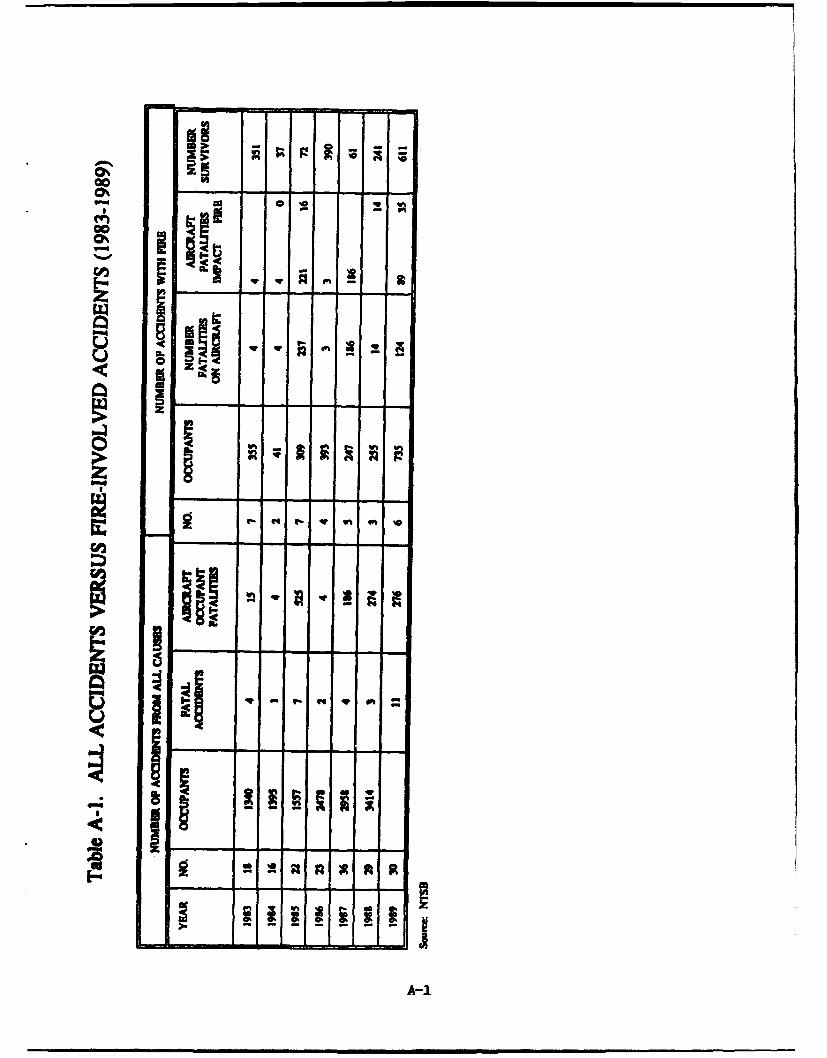
2.3 NATIONAL TRANSPORTATION SAFETY BOARD.
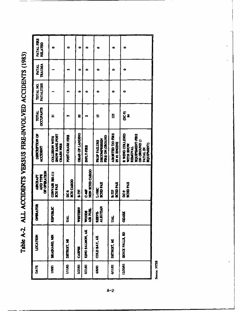
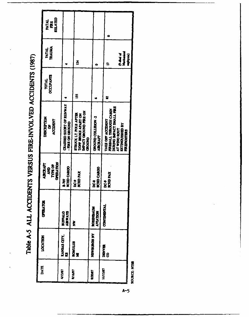
The NTSB provided a composite listing of all continental U.S. aircraft accidents that resulted infires from years 1983-1989. Appendix A contains these charts. These charts depict 15 transportcategory aircraft accidents which occurred during the period 1983 - 1990, where a post-impactfire occurred, and the accident was identified as a "survivable" accident. To determin thecompleteness of this set, four sources were used for additional information:
0 NTSB Aircraft Accident Briefs (Received on March 5, 1993 from NTSB, Washington,
* NTSB Annual Review of Aircraft Accident Data, U.S. Carrier Operations, Calendar Years
1985, 1986, 1917
* NTSB Individual Aircraft Accident Reports
a Flight Safety Foundation - Flight Safety Digests
8

2.3.1 NTSB Aircraft Accident Briefs.
The results of the analysis of these briefs are summarized as follows:
Thirty-four accident briefs were reviewed. After review and filtering out those accidentswhich were not applicable, the data was reduced to 15 potentially useable accidents. Oneadditional accident was added to the data set from the chart provided by NTSB. Thisaccident was a ground-collision accident between a B-727 and DC-9 on 12/13/90 inDetroit in which the DC-9 caught fire. Thus, the preliminary data set consisted of 16potentially useable accidents where a post-impact fire occurred.
Of these 16 potentially useable accidents, none of the NTSB reports analyzed to daterevealed any useful data on fuel ignition sources, fuel fire propagation histories, or fuelline/fitting effectiveness.
2.3.2 NTSB "Annual Review of Aircraft Accident Data".
This publication presents the record of aviation accidents involving revenue operations of U.S.Air Carriers including "Commuter Air Carriers" and "On-Demand Air Taxis" for one calendaryear. Three reports were available for the years 1985, 1986, and 1987. Although primarilystatistical in nature, these reports included a table in each which is a "Ust of Accidents, CFR Part121, 125, 127 Operations." The accidents listed were then compared with the NTSB AircraftAccident Briefs involving post-impact fire to insure completeness in the data set. Unfortunately,CFR Part 121, 125, and 127 operations accidents are not broken out and categorized separately.Accordingly, some degree of knowledgeable interpretation of the table was made, CFR Part 121air carrier operations were filtered out and a positive correlation between the two separate NTSBaircraft accident data sources was obtained.
2.3.3 NTSB Aircraft Accident Repors.
Review of several available NTSB reports determined that the contents do not contain useabkinformation on ignition source(s), fuel system deformation/failure during impact, integrity oradequacy of aircraft fuel systems, etc. Additional field investigators data acquired during anaircraft accident might provide such detail. Attempts to obtain the data were unsuccessful.
2.3.4 Flight Safety Foundation - Flight Safety DigesL
The Flight Safety Foundation (FSF) is a well-recognized and respected international membershiporganization dedicated to improving aviation safety. One of its publications is the Flight SafetyDigest (FSD), a monthly publication which primarily addresses real or potential aviation safetyissues and periodically provides aviation statistics, briefs, and related information on aircraftaccidents and incidents, both domestically and worldwide. Review of the digests published overthe past five years (60 issues) revealed good correlation between their tabulation of aircraftaccidents with post-impact fire and the briefs received from the NTSB cited earlier. Additionalcandidate accidents were identified in the Digest that were not in the NTSB briefs. This was dueto the fact that there were either foreign aircraft involved, or non-Part 121 operations, andtherefore did not meet our designated criteria.
9

2.4 AIRCRAFT MANUFACTIR.
The information obtained from air',raft manufacturers was analyzed and summarized as follows:
2.4.1 Boeing 747.
General - The hose assemblies are installed within a tubular aluminum shroud and carry the fuelthrough the fuselage to the APU. Flexible hose is used as the fuel carrying medium to obtainthe maximum fuel line integrity in the event of damage to the surrounding structure.
Fuel System Discussion - The fuel in this aircraft is contained in a center wing tank, tip reservetanks, and 4 main wing tanks. Auxiliary tanks are added between the reserve tank and theoutboard main tank in some models. The maximum fuel capacity is 51,100 gallons.
Pressure refueling and defueling is performed with two 2 1/2 inch MIL-S-25896D fuelingadapters.
* Fuel is pumped from the center wing tank first until it is empty then from the main wingtanks. Fuel can be pumpoe and cross-fed between all tanks and engines.
* A fuel scavenge pump in the center wing tank transfers fuel that is unavailable to thecenter wing tank boost pumps to the no. 2 main tank.
0 A water scavenge system scavenges water from low points in the main tanks and pumps
it to a point near the boost pump inlet.
0 A schematic of the basic fuel system is shown in appendix B.
Fuel System Comnonents and Features.
0 Line Sizes - The main fuel system uses 1.5-in to 2.5-in pipe, and the scavenge systemuses 3/4-in pipe.
* Boost Pumps - Electrically driven, 7200 rpm centrifugal pumps with a 20,000 IMw ratingat 13 psig are used. Four rnu continuously, 8 are supplied. Cruise flow is approxmately8000 pph. zero flow pressure is approximately 20 psig.
0 Transfer & Jetuison - Four additional pumps identical to the boost pumps are supplied.
* Fuel Scavenge and APU - These awe vane pumps. The AN pump is battery powered andis used to supply fuel to the AM when 115t200 VAC power is not available.
• Water Scavenge - Eight tanall jet pumps with 0.064-in nozzles ame used which runcontinuously.
* Filters - The boost pumps, override pump, APU pumps, and fuel scavenge pump have 4mesh screens on the inlets. No other filters are supplied with the airframe fuel system.
10
Vent System - The vent system utilizes small honeycomb mesh flame arrestors.
Suction Feed - The suction feed condition during flight would occur only as a result ofmajor pump and/or electrical failure. The aircraft can operate in the suction feedcondition.
Pressure Refueling - Normal pressure refueling is performed with 2 hoses from the leftside of the aircraft. The 2 l/2-in MIL-25896D adapter is used. This system utilizes arefueling valve which contains pilot float valves and small bleed lines of approximately0.125 inch diameter.
0 Refuel Distribution Lines - Several 4 to 5 foot lengths of 2-in pipe with 1/8-in holes areused to bleed off static charge and distribute the fuel.
* Heat Exchangers - Hydraulic fluid/fuel heat exchangers are used in this aircraft.Hydraulic fluid is on the tube side and fuel is on the shell side. The fuel is used as astatic heat sink.
a Fuel Quantity Gauging System - A capacitance type fuel quantity gauging system is usedon this aircraft. No thermistor type point level sensors are used.
* The APU is supplied by Garrett Airesearch; their part no. is GTCP660-4. This unit has10- and 25-micron paper filters and a 4000 rpm gear pump that has 4000 pph flow at 600psig. The max bypass ratio is 3.6:1. There are 8 primary nozzles with a diameter of0.014 inch. The fuel control bypass flow metering system uses a 0.020-in to 0.060-inflow passage.
2.4.2 McDonnell Dou-las DC-10-40.
Fuel System Discussion - The DC-10-30 and 40 are the long range versions of this aircraft,which have a fuel capacity of 36,200 gallons (gal). There are three main tanks, one for eachengine, plus auxiliary tanks in the center wing box.
Aircraft refueling can be accomplished through either two or four standard 2 lf2-in MIL-A-25896D adapters, two of which at installed on each wing. T maximum initial flow ratedthrogh each adapter at 50 pounds per squae inch gauge (psig) supply pressure is approximately600 gal/nin. This system utilizes refueling flow. This system can also be used defuel theaircraft.
The fuel transfer philosophy during flight is as follows. Fuel is transferred from the auxiliarymanks to the main wing tanks for use. The main wing tank fuel is used in three segments
consisting of the inboard, outboard, and wing root areas. The inboard compartment fuel is usedfirst, with the outboard compmarment held full for wing srtural considrations. Late in theflight the outboard fuel is transerred inboard for use and then fuel in the wing root area is usedlast. Float switches and indicator lights are used to indicate the fuel usage scheduling and statusto the flight engineer. A water scavenging system employing jet pumps is used to remove waterfrom the tank low points and mix it with the fuel near the boost pump inlets. The motive flow
11
comes from the engine feed lines and the secondary flow of water and fuel is drawn up through
tubing rakes whose inlets ame located in the tank low points.
A schematic of the basic fuel system is shown in appendix B.
Fuel System Components and Features.
Line Sizes - The main fuel system use, 2.0-in to 3.0-in outside diameter pipe.
The scavenge and transfer system, uses 1/2-in to 5/8-in pipe.
Boost Pumps - Electrically driven, 8000 revolutions per minute (rpm) centrifugal pumpsrated at 46,000 lWhr at 17 psig are used. Twelve are supplied for boost and transfer andat least 4 run continuously. Five are in each inboard wing tank and two are in theauxiliary tank. Fuel serves as a coolant for the electrical winding of these pumps.Nominal cruise flow is approximately 5000 lM/r, and pump dead head pressure is 30 psi.
* Ejector Pumps - Fourteen ejector pumps are supplied, 4 for transfer and 10 forscavenging. Five are located in each wing and 4 in the auxiliary center section tank. Thescavenge pumps run continuously.
S Filters - The boost pump inlets have 5 mesh screens, and no other filters are supplied.
* Suction Feed - The suction feed condition during aircraft flight would occur only as aresult of major pump and/or electrical failure. The fuel system design, however, providesfor continuous operation under suction feed conditions.
* Vent System - The vent system provides for equalization of tank pressure with ambientpressum. This system incorprates vent float valves and fine honeycomb mesh flamearrestors to prevent the possibility of lightning-ignited fuel vapor causing flames to travelinto the tank space. Bypass valves are provided to avoid tank over pressure in the eventof arrestor plugging.
Jettison System - A jetison system is provided which utilizes the centifugal pumps todump fuel overboa. The maximum rate obtainable is 6000 fbibninute.
Pressure Refueling - Nornmal pressure refueling is performed with two hoses from oneside of the aincraft; four hoses and both sides can be used. The 2 1(2-in ML-A-25896Dadapter is used. This system utilizes a refueling valve which contains pilot float valvesand small bleed lines of 0.125 inch maximum.The maximum initial fueling rate is 2170gallmin. using four adapters and 50 psig supply pressure while filling all tanks.
Refuel Distibution Manifold - A distribution line in each wing containing 1/4-in holesis used to reduce static charge build-up and distribute fuel evenly.
Heat Exchangers - There are no airframe supplied heat exchangers using fuel as a heatsink on this aircraft
12

Fuel Quantity Gauging System - A capacitance-type fuel quantity gauging system is usedon this aircraft. No thermistor-type point level sensors are used.
Auxiliary Power Unit (APU) - The APU is supplied by Garrett Airesearch; their part no.is TCSP-700-4. This unit has 10- and 40-micron paper filters, and a 6655 rpm gear pumpwhich supplies 2000 pph at 750 psig. There are 18 nozzles, 9 with a diameter of 0.0125inch and 9 with a diameter of 0.014 inch. The fuel control bypass metering system usesa flow passage which varies from 0.020 inch to 0.060 inch. This unit can be used eitheron the ground or in flight. The bypass system recirculates fuel back to the gear pumpinlet, not to the bulk fuel.
* The pylons for all Douglas airplanes have undergone a Pylon Mock Review to addressall fire protection criteria including a first Article Inspection. The items of review are asfollows: all pylon fuel lines and hydraulic lines are steel, not aluminum; all connectionsare eliminated ff possible; ff not, all connections are shrouded and drained overboard;proximity and location of electrical lines to fuel lines are evaluated; clipping of electricalfeeder cables insure a separation will not impact on a fuel line to arc and penetrate.
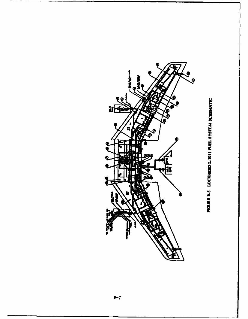
2.4.3 Lockheed LI011-500.
Fuel System Discussion - The fuel in this aircraft is contained in six tanks - (two tanks in eachwing and two center section tanks) with a total capacity of 32,000 gallons.
Pressure refueling and defueling is accomplished with the standard 2 1/2-in ML-A-25896adapters, two of which are located on each wing. Automatic shutoff valves are used to controlthe fueling operation.
The cross feed system permits any engine feed tank to supply fuel to any engine, but does notallow tank to tank transfer. This is accomplished with ejector pumps and fuel transfer valves inthe fuel transfer system. During takeoff and climb each engine is fed from its own tank. Whencruise altitude is reached, the left and right no. 2 wing tanks are shut off and the center tanks areused until empty. Each engine is then fed from its own wing tank until the end of the flight.
A water scavenging system using compound jet pumps with inlet rakes draws water and fuel
from variom low points in the various tanks and deposits it in the boost pump collector boxes.
A basic schematic of the fuel system is shown in appendix B.
Fuel System ConMonets anFeatures.
Line Sizes - The main fuel system uses 1.5-in to 2.5-in pipe, and the scavenge systemuses 5/8-in lines.
'Boost Pumps - Electrically driven, 10,000 rpm centrifugal pumps with a 45,000 lWhrrating are used. Four dual-element pumps are provided, one in each wing tank. Threeelements run continuously, six run during landing and takeoff. Cruise flow isapproximately 5500 pph, dead head pressure is 40 psi.
13
Ejector Pumps - Thirty-four jet pumps are used in the scavenge and transfer system.Eighteen of these are compound pumps with a single motive flow stream and multiplesecondary flow streams. They are used to scavenge water and transfer fuel. The wingscavenge system operates continuously, and the center tank system operates under manualcontrol.
Filters - Fourteen mesh screens are used in the boost pump inlets and in the jet pumpmotive flow lines.
Suction Feed - The suction feed condition during aircraft flight would occur only as aresult of major pump and/or electrical failure.
Vent System - The vent system contains honeycomb mesh flame arrestors with less then0.01 inch openings.
Pressure Refueling - Pressure refueling is performed using the 2 If2-in MIL-A-25896Dadapters, four are supplied, two on each wing. Automatic shutoff valves with pilot valvesare used in this system which contain small lines 0.060 inch or greater.
* Heat Exchangers - No heat exchangers are used in the fuel system of this aircraft.
* Fuel Quantity Gauging System - A capacitance type fuel quantity gauging system is usedon this aircraft
0 Thermistor bead point level sensors are used for low-level jettison pump shutoff and low-level nwasker shutoff functions.
0 Auxiliary Pbwer Unit (APU) - The APU is supplied by Hamilton Standard, part No. ST-6L-73. The engine portion of this unit consists of a Pratt & Whitney Canada STL73engine and a fuel control supplied by Aviation Electric.
a The fuel control internal bypass metering valve utilizes a piston in a sleeve with 1/S-inhole.
* The engine utilizes a 6500 rpm, 1400 pph, 100 psi gear pump with a bypass system thatreturns bypassed fuel to the pump inlet. The pump outlet has a 1-micron paper filter.
2.4.4 Airbus Industric A-3 10.
Fuel System Discmssion - The fuel in this aircraft is contained in five tanks - center wing andright and left outdxord and inboard. The total fuel quantity is 14, 531 gallons.
Defueling is accomplished using two standard 2 1/2-in fueling adapters on the right side of theaircraft.
14
Fuel is used in the order. center, inboard, and outboard except during takeoff when the centertank is not used. The tank sequence is automatic, but can be controlled manually at any time.A cross feed system allows both engines to feed from one side, or all fuel to be used in oneengine.
Two jet pumps are used for fuel scavenging and to keep the boost pump collector boxes full.
A basic schematic of the fuel system is shown in appendix B.
Fuel System Components and Features.
Line Sizes - The engine feed lines are 2 inch, refuel and defuel are 1.5-in to 3.0-in, andthe APU feed is 3/4-in.
Boost Pumps - Electrically driven, 6000 rpm centrifugal pumps with a 40,000 lbhr flowrating at 9 psig are used. Ten are supplied, six run continuously from the start of theflight, reducing to four as the tanks are emptied. The inner and center tank pumps havea zero flow pressure of 37 psig, the outer tank pump 18 psig.; cruise flow isapproximately 4000 pph.
Ejector Pumps - Two jet pumps, one in each wing, are used to keep the outer tank pumpcollector box full. They run continuously.
* Suction Feed - Suction feed during aircraft flight would occur only as a result of majorpump and/or electrical failure.
0 Filters - The boost pump inlets have 8 mesh wire screens. No other filters are suppliedwith the airframe.
* Pressure Refueling - Two standard 2 1/2-in adapters are used for pressure refueling. Anautomatic shutoff valve utilizing a pilot valve with small orifices is used in this system.Te system is also used for suction or pumped defueling.
* Fuel Distribution - Several diffuser sections, consisting of I to 2 foot lengths of 2-in pipewith l/8-in-diameter holes, are used to distribute the fuel and reduce static charge build-up during the fueling operation.
* Vent Systems - The vent system contains fine honeycomb mesh flame anestors.
* Heat Exchangers - No fuel heat exchangers are supplied with airframe.
0 Fuel Quantity Gauging System - A capacitance type fuel quantity gauging system is usedon this aircraft. Thermistor type point level sensors are used for high- and low-levelsensing and to shut-off the center tank pumps when the tank is empty.
Density Measurement - A fuel density measurement device called a Cadensicon issupplied with this aircraft.
15

It utilized a mass balance method to measure fuel density and a sensor which measuresfuel dielectric constant.
Auxiliary Power Unit (APU) - A Garrett GTCP-311-250 unit is supplied. This unit hasa 10-micron synthetic fiber filter, and an 8300 rpm gear pump that supplies 2100 pph at700 psig. Twelve fuel nozzles are used, 6 with an opening of 0.012 inch and 6 with anopening of 0.014 inch. The fuel control bypass metering line varies from 0 to 0.020 inch.
16
3. CONCLUSIONS.
Based on the analysis of all data obtained, it is concluded that:
a. There was insufficient data to firmly conclude that fixed or flexible fuel lines have eithercontributed to or prevented post-crash fire incidents.
b. There appears to be a benefit to the flexible fuel line technology.
c. The question of the value of the flexible versus rigid fuel line and its contribution to theloss of life is an extremely important question that needs to be addressed further. A test programmay even be warranted.
17
4. REFERENM'.
Aircraft Crash Survival Design Guide. Volume V - Aircraft Post Crmsh Survival, USARTL-TR-79-22E, January 1980, paragraph 4.2.2 Fuel Lines, p. 57.
Fuel Containment Conceeps - Transport Category Airplane_ FAA Report DOT/FAA/Cr-87/18,November 1987, paragrap 6.7, General Approaches, Approach No. 1, pp. 6-40 to 6-43.
18

Appendix A
Summary of NTSB Accident Data
a %-Go
0%
ool
-A-
VIAJ
al - nm u
o U' 1
I I IloN!
gullA-2

- -
-J
I- 0 0
@00%
U
og
ii"iii'
U - -
iii� 4a.
iiIi!
= * = = A
A-3

00 04%aw -C
C4 C4
0 .i ~~
a S m.
W~ilIIi i111li
C42* *~
C.) 0 z 0
s_' i iVA-4
o
'4W0-4
, i nI
L,,
mU
A-5

0%0
S 14
Zr,
-a-

Appendix B
Aircraft Manufacturer Schematics

I if
B-1
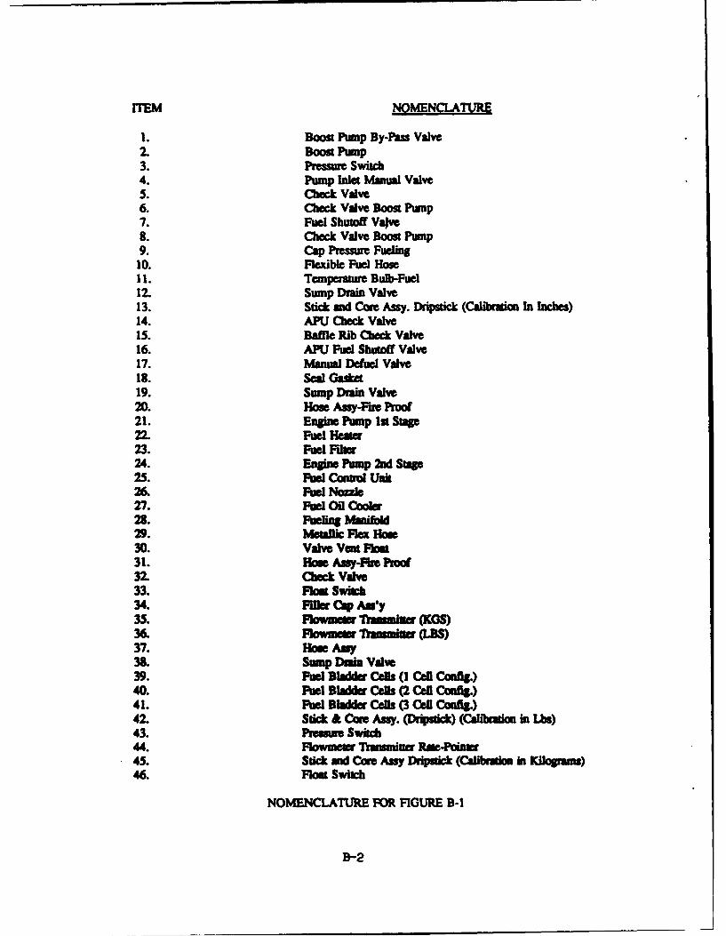
17FEM NOMENCLATURE
1. Boost Punp By-Pa. Valve2. Boost Pump3. Pressure Switch4. Pump Inlet Manual Valve5. Check Valve6. Check Valve Boost Pump7. Fuel Shutoff Vajve8. Check Valve Boon Pnump9. Cap Pressure Fueling10. Flexible Fuel Hose11. Temperature Bulb-Fuel12. Sump Drain Valve13. Stick mid Cao Assy. Dripstick (Caibrato In Inces)14. APU Check Valve15. Baffle Rib Check Valve16. APU Fuel Shutoff Valve17. Manual Defuel Valve18. Seal Gasket19. Sump Drain Valve20. Hoe Assy-F're Proo21. Engine Pump 1st Stage22. Fuel Heater23. Fuel Fiber24. Engine Pump 2nd Sta25. Fuel Comruo Unit26. Fuel Nozzle27. Fuel Oil Cooler28. Fueing MWOl29. Metallic Flex How30. Valve Vnt FoM31. Hoe Assy-Fue Proof32. Check Valve33. Flost Switch34. Fife Cap Au'y35. a- m eu m ranuminea (KOS)36. Fowmemr Tmmmiu (LS)37. Ho mAny38. Sump Drain Valve39. Fuel bAdder Cels (I cell Cafg)40. Fuel Bladder Cells (2 Cell Config.)41. Fuel Bladder Cel (3 Cell Config)42. Stick & Coew Asy. (Drip ) (Cdalbmion in Lbs)43. Pwme Switch44. Flowmer Transmiuter Ra -Ain45. Stick and Core Assy Drpuck (Caliration in Kilogramm)46. Float Switch
NOMENCLATURE FOR FIGURE B-I
B-2

B il
111
RI!3/l f B 3

94
aa#4Z
.7 i"--- , "i II•
I I
bn
B-4.
I~ills i
IT
B-5

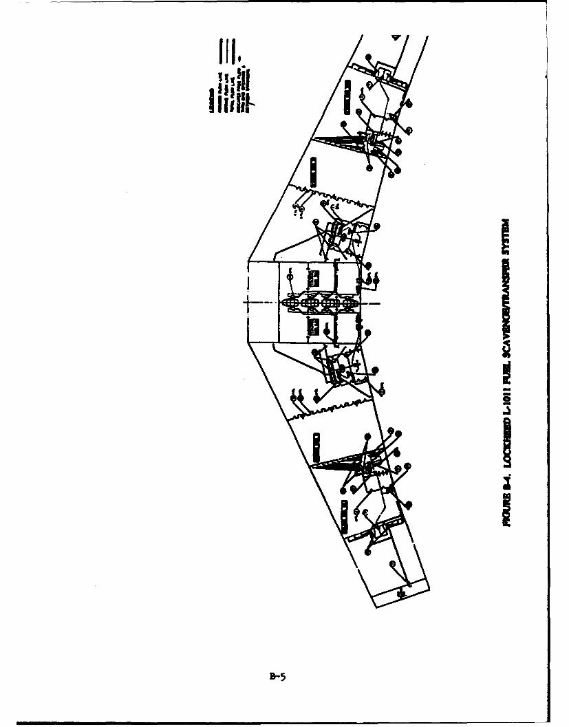
- NOuULAUR
1. FLAPPER VALVE2. FLAPPER VALVE3. FLAPPER VALVE4. FLAPPER VALVES. FLAPPER VALVE6. FLAPPER VALVE7. CHECK VALVES. JET PUMP-SMALL9. JET PUMP-LARGE10. JET PUMP-COMPOUND11. CHECK VALVE12. STRAINER-CHECK VALVE13. TRANSFER & SCAVENGE MOTIVE FUEL VALVE14. JET PUMP-COMPOUND
NOMENCLATURE FOR FIGURE B-4.
R-6
III0I
D-7
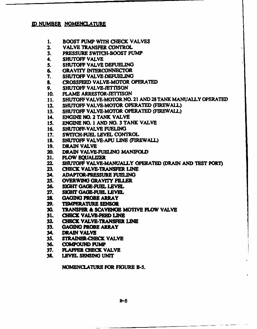
1. BOOST PUMP WIh CHECK VALVES2. VALVE TRANSFER CONTROL3. PRESSURE SWITCH-BOOST PUMP4. SHUTOFF VALVES. SHUTOFF VALVE DEFUELING6. GRAVITY IN`ERCONNECrTR7. SHUTOFF VALVE-DEFUELING8. CROSSFEED VALVE-MOTOR OPERATED9. SHUTOFF VALVE-JErTISON10. FLAME ARRESTOR-JEI"fSON11. SHUTOFF VALVE-MOTOR NO. 21 AND 28 TANK MANUALLY OPERATED12. SHUTOFF VALVE-MOTOR OPERATED (FIREWALL)13. SHUTOFF VALVE-MOTOR OPERATED (FIREWALL)14. ENGINE NO. 2 TANK VALVE15. ENGINE NO. 1 AND NO. 3 TANK VALVE16. SHUTOFr-VALVE FUELING17. SWITCH-FUEL LEVEL CONTROL18. SHUTOFF VALVE-ANU LINE (FIREWALL)19. DRAIN VALVE20. DRAIN VALVE-FUELING MANIFOL21. FLOW E•UALJ7iR22. SHUTOFF VALVE-MANUALLY OPERATED (DRAIN AND TEST PORI)23. CHECK VALVE-TRANSFER I.NE24. ADAPTOR-PRESSURE FUELING25. OVERWINO GRAVITY FIJER26. SIGH GAGE-FUL LEVEL.27. SIGHT GAGS-FUEL LEVEL28. GAGING PROBE ARRAY29. 11MPERATIURE SENSOR30. TRANSFER & SCAVENGE MOTIVE FLOW VALVE31. CIECK VALVE-FED LI32 CHBCK VALVE-TRANSFER LINE33. GAGINO GPROBE ARRAY34. DRAIN VALVE35. STRAINER4-OCK VALVE36. CONFOUND PUW37. FLAPPER CHECK VALVE31. LEVEL SENSING UNIT
NOMENCLATURE FOR FIGURE B-S.

Appendix C
Committee Position: No. 9 "Crashworthy Fuel Systems"
The Airline Pilots Association (ALPA) Accident Survival Committee in Committee Position No.9 has determined that investigation of the various engineering techniques used to constructcrashworthy fuel systems should be given utmost priority. Among the various ftre preventionproposals the committee is considering is the Engine Fuel Line Disconnect. The committeerecommends that FAR 25.993 be amended to include a requirements that the fuel feed linebetween the wing/pylon structure and the engine fuel inlet point on turbine-powered aircraftincorporate a self-closing breakaway fitting which automatically closes off the flow of fuel in theevent of accidental separation of the engine from the pylon. Further, the use oi such breakawayfittings should be required at locations throughout the fuel system that are known as likely pointsof airframe distortion or failure due to crash forces. This is based on the U. S. Army'sestablished design criteria for breakaway, self-closing fuel connections used in conjunction withcrashworthy fuel tanks in helicopters that has proven successful. The ALPA Accident SurvivalCommittee has declared that breakaway fuel fittings could have prevea.ied the destruction of bothan ONA DC-10 following an engine explosion and fire during takeoff at JFK Airport, and theEAL DC-9 following failure of the fuselage at the aft pressure bulkhead on landing at FortLauderdale, Florida. The full text of Committee Position: No 9 "Crashworthy Fuel Systems"is contained in the following pages.
C-1
COMMUTEE POSITION: NO. 9
CRASHWORTHY FUEL SYSTEMS
Construction improvements to the forerunner of the high-altitude, jet-powered aircraft haveresulted in an airframe capable of remaining relatively intact when sustaining the survivableimpact forces prevalent in those accidents occurring on or in the vicinity of the airport runway.There is still, however, the ever-present danger of fire caused by the spillage of highly flammableaviation fuels. Many aircraft occupants survive an accident, only to perish in the ensuing fire.
Programs either to prevenE the occurrence or to minimize the severity of aircraft fires shouldreflect an appreciation of the crash-fire profile. Studies conducted by the International CivilAviation Organization (ICAO), the British CAA, and ALPA indicate that 80% of aircraftaccidents occur during landing or takeoff in the vicinity of the runway and overrun area. Thebulk of these accidents occur when aircraft are moving at relatively low speeds and most are, orshould be, survivable. Fire is the predominant hazard of typical accidents occurring in theseareas. ICAO statistics relating fatalities occur during or subsequent to accidents within airportboundaries; 72% of aircraft fire deaths occur within the same area. Almost all of the fires arecaused by inadequate fuel containment.
Investigation of the various engineering techniques used to construct crashworthy fuel systemsshould be given utmost priority. At present, the ALPA Accident Survival Committee isconsidering the following fire prevention techniques:
Low Volatility FuelProposal: The appropriate sections of FARs 25 and 121 should be amended to requirethat fuel used by turbine-powered aircraft must have a flash point not less than 100degrees Fahrenheit.
Explanation and justification: It is clear that thee are significant safety benefits to bederived from the exclusive use of Jet A (kerosene) fuel in tubine-powend aircraft,particularly when such aircraft are involved in accidents where spillage has occurred. JetA fuel is more difficult to ignite than is Jet B fuel; and, when ignited, Jet A fuel flamespropagate at a much slower rate than do those of ignited Jet B fuel, especially at nomalfuel temperatures. These fuel variations can be vitally important as they rela toaccidents during which a short delay in fire development would allow occupants toescape. The proposed rule amendment should permit adequate time for opeatos toarrange the necessary transport, storage, and dispensing of equipment at airprts whereJet A fuel is not yet available.
Vent System Flame AttestersProposal: That FAR 25.975 be amended to include a requirement for the prevention orsuppression of flame propagation in fuel tank venting systems when flammable fuel-airmixtures are likely to exist. Such a system must not impair the function of the ventingsystem under the range of climate conditions for which the aircraft is approved.
C-2

Explanation and Justification: Vent system outlets are points at which fuel vapors areexposed to possible ignition by sparks or ground fires. This can occur if there is fuelspillage or an accident during which a ground fire develops in the vicinity of the ventoutlet. Flame-arresting and flame-suppressing designs that have been proven effective arenow available and offer a significant measure of protection against tank explosion.
Engine Fuel Lin.e DisconnectProposal: That FAR 25.993 be amended to include a requirement that the fuel feed linebetween wing/pylon structure and the engine fuel inlet point on turbine-powered aircraftincorporate a suitable self-closing breakaway fitting which automatically closes off theflow of fuel in the event of accidental separation of the engine from the pylon. Further,use of such breakaway fittings should be required at locations, throughout the fuel system,that are known or likely points of airframe distortion or failure due to crash forces.
Explanation and Justification: The U.S. Army has established design criteria forbreakaway, self-closing fuel connections used in conjunction with crashworthy fuel tanksin helicopters, and has accumulated favorable service experience with this system.Breakaway fuel fittings could have prevented the destruction of both an ONA DC-10,following an engine explosion and fire during takeoff at JFK Airport, and the EAL DC-9,following failure of the fuselage at the aft pressure bulkhead on landing at FortLauderdale, Florida.
For many years, the requirements of FAR 25.561, which am also applicable to the structure offuselage fuel tanks by reference in FAR 25.963(d), have been recognized as being inadequate andobsolete. Tests have shown that properly restrained occupants can easily survive 20 G cashdeceleration forces. Therefore, we advocate early development of an amendment to FAR 25.561that will provide the fuel tanks with a label of strength com mesua with human survivability.
It is recommended that the FAA initiate a program to crash tent those protective measur•s forwhich basic research and development have already been concluded. At least the followingshould be included:
1. crashworthy fuselage fuel containers conforming to U.S. Army h ope fuel Wtank
2. operational inerting systems.
We believe that prtotype designs of various forms of explosion prevention system and crash-resistant fuel tank systems should be installed in aircraft having structural and cash responsecharacteristics similar to contempor large turbine transport aicraft. These systems should thenbe crash tested to demonstrate the effectiveness of each method and to obtain more reliableinformation on weight, cost, and other penalties. Such a program should be sponsored by theFAA, supported and assisted by industry and other government agencies. And-misting fueladditives are particularly promising means of drastically reducing the post-crash fire hazard.However, additional research and development work are necessary. It is recommended that theFAA assign sufficient priority and funding to enable follow-up research and development toproceed as rapidly as possible.
C-3

Fuel Containment.Ignited fuel spillage inside the fuselage area will create almost instantaneously an unsurvivablecabin environment. In the event of a water-contact accident, spilled fuel floating on the waterwill cause serious damage to the lungs and respiratory tracts of survivors, potentially resultingin deaths.
Current requirements pertaining to fuselage fuel tanks include provisions for:. isolating the tankfrom passenger areas (FAR 25.967[e]); withstanding emergency landing conditions (FAR25.963[dJ); and protection from ground contact. The emergency landing conditions are statedin FAR 25.561 as: upward 2.0 G; forward 9.0 G; sideward 1.5 G; and downward 4.5 G. Theseforces are known to be much lower than a person properly restrained in a seat can withstandwithout injury.
Wing-center-section fuel tanks are usually constructed as flexible, nonmetallic cells located withinthe wing box-bounded by spar webs, bulkheads, and upper and lower carry-through skin. Thewing structure surrounding the cell is consequently strong and resistant to rupture. Areas in thefuselage outside the wing carry-through structure are less protected and more vulnerable to crash-damage. This results in increased potential for fuel spillage and fire, and decreases theprobability of a successful postcrash evacuation.
The U.S. Army's development and application of crashworthy fuel systems for helicopters hasbeen very successful. This design criterion is available and can be applied to the design ofcommercial transport aircraft-with some weight and capacity penalties. Weight penalties couldbe reduced to reasonable values by the selection of design requirements appropriate to the tanklocadon.
Proposal: Any fuel carried in the wing center section of the fuselage fuel tank shallbe contained in a tank-within-a-tank, the inner tank to be construct ofcrash-resistant material. Such tanks shall be equipped with tbeakawayself-sealing connections. All vent lines for these tanks shall be equippedwith a vent-flame-suppression system.
C-4


![918 todd[1]](https://img.pdfslide.net/doc/110x75/55d713f6bb61eb81548b46c7/918-todd1.jpg)