Embed Size (px)
Citation preview
C. ADAMS MIDDLE SCHOOL ACADEMIC BUILDING SEISMIC VULNERABILITY ASSESSMENT For the WEST CONTRA COSTA UNIFIED SCHOOL DISTRICT 1108 Bissell Avenue Richmond, CA 94801 Prepared by: DASSE Design Inc. 135 Main Street, Suite 850 San Francisco, CA 94105 DASSE Project No. 08B245
Final Report December 31, 2008
C. Adams Middle School December 31, 2008 Academic Building
1
TABLE OF CONTENTS
1.0 Introduction/Scope of Study ............................................................. 2
2.0 Building Description ......................................................................... 2
3.0 Seismic Vulnerability Assessment.................................................... 4
3.1 Evaluation Criteria: .................................................................... 4
3.2 Computer Model: ....................................................................... 5
3.3 Findings:..................................................................................... 8
4.0 Anticipated Seismic Performance................................................... 13
5.0 Executive Summary ........................................................................ 16
APPENDIX A............................................................................................. A-1
C. Adams Middle School December 31, 2008 Academic Building
2
1.0 Introduction/Scope of Study A limited seismic evaluation of Charles Adams Middle School was performed by DASSE in 2002 to provide preliminary qualitative evaluations of the campus building structure, to identify life safety hazards and other deficiencies and to prioritize remediations. At that time, the structure of the Academic Building was noted to posses certain discontinuities which could pose significant hazards. In 2004, DSA published the “AB300 Report” that identifies non-wood frame, public school buildings which are considered to be potentially hazardous. The Academic Building is on this list. The purpose of this study is to conduct an in depth seismic vulnerability assessment of the Academic Building following the criteria and procedures of ASCE-31 – 03, “Seismic Evaluation of Existing Buildings” referred to as “Tier 2”.
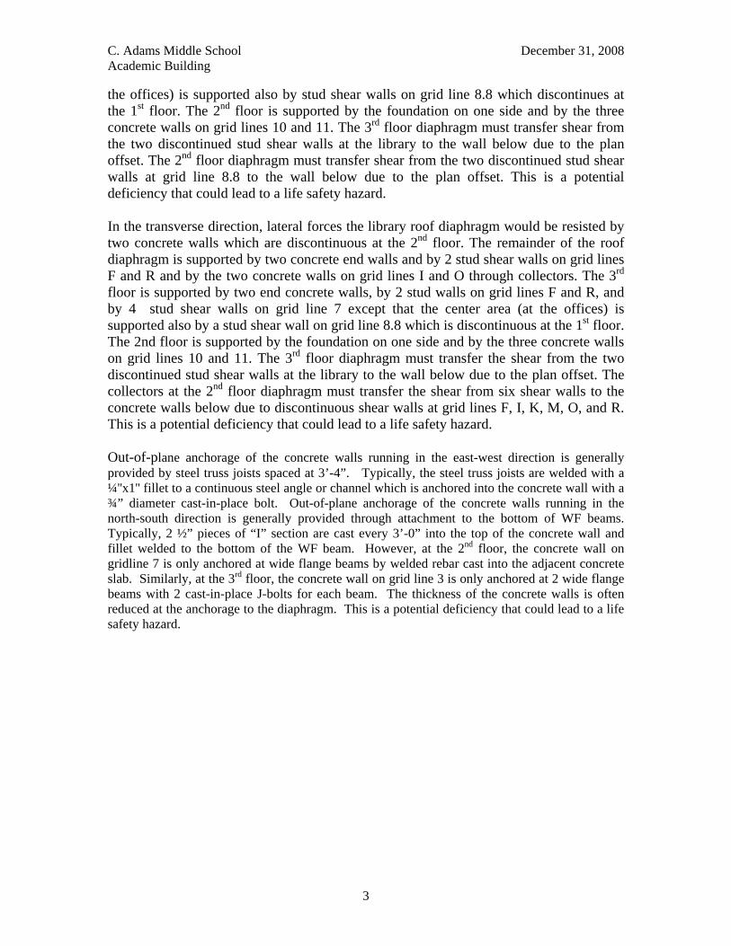
2.0 Building Description According to the original construction documents, the Academic Building was designed to comply with the 1955 Uniform Building Code. The building was constructed on a sloping site where it is a two-story in front (east side) and three-story in the rear (west side). In general, all roofs and raised floors are constructed of open web steel joists spaced 3' to 5' on centers, supporting wood diaphragms composed of 5/16'' plywood over 2'' T & G straight sheathing. The steel joists are supported on steel beams and/or concrete walls where they occur. The steel joists were pre-engineered and plant fabricated; therefore, not all details appeared in the drawings, such as the plant assembly details and field installed bridging. Steel beams are supported by steel columns. The foundation system consists of spread footings supporting steel columns and continuous footings supporting interior and exterior concrete walls and wood stud shear walls. The slab on grade is 5'' unreinforced at the ground floor and 5'' reinforced with #3 at 18'' on center at the second floor where the building “steps” into the hillside. The vertical element of the lateral system is composed of wood stud walls sheathed with 3/8'' plywood and cast-in-place concrete walls. The typical nailing of the wall plywood is 8d at 2'', 3'' and 4'' on centers. In the longitudinal (North-South) direction, lateral forces at the library roof would be resisted by concrete walls on one side and the other side is a Clerestory, for which the diaphragm is subjected to torsion. The remainder of the roof diaphragm is supported by a stud wall sheathed with plywood on grid line 7. The central area (at the offices) is supported by two stud shear walls which are discontinuous at the 2nd floor. The 3rd floor diaphragm is supported by the stud shear wall on grid line 7 except that the center area (at
C. Adams Middle School December 31, 2008 Academic Building
3
the offices) is supported also by stud shear walls on grid line 8.8 which discontinues at the 1st floor. The 2nd floor is supported by the foundation on one side and by the three concrete walls on grid lines 10 and 11. The 3rd floor diaphragm must transfer shear from the two discontinued stud shear walls at the library to the wall below due to the plan offset. The 2nd floor diaphragm must transfer shear from the two discontinued stud shear walls at grid line 8.8 to the wall below due to the plan offset. This is a potential deficiency that could lead to a life safety hazard. In the transverse direction, lateral forces the library roof diaphragm would be resisted by two concrete walls which are discontinuous at the 2nd floor. The remainder of the roof diaphragm is supported by two concrete end walls and by 2 stud shear walls on grid lines F and R and by the two concrete walls on grid lines I and O through collectors. The 3rd floor is supported by two end concrete walls, by 2 stud walls on grid lines F and R, and by 4 stud shear walls on grid line 7 except that the center area (at the offices) is supported also by a stud shear wall on grid line 8.8 which is discontinuous at the 1st floor. The 2nd floor is supported by the foundation on one side and by the three concrete walls on grid lines 10 and 11. The 3rd floor diaphragm must transfer the shear from the two discontinued stud shear walls at the library to the wall below due to the plan offset. The collectors at the 2nd floor diaphragm must transfer the shear from six shear walls to the concrete walls below due to discontinuous shear walls at grid lines F, I, K, M, O, and R. This is a potential deficiency that could lead to a life safety hazard. Out-of-plane anchorage of the concrete walls running in the east-west direction is generally provided by steel truss joists spaced at 3’-4”. Typically, the steel truss joists are welded with a ¼''x1'' fillet to a continuous steel angle or channel which is anchored into the concrete wall with a ¾” diameter cast-in-place bolt. Out-of-plane anchorage of the concrete walls running in the north-south direction is generally provided through attachment to the bottom of WF beams. Typically, 2 ½” pieces of “I” section are cast every 3’-0” into the top of the concrete wall and fillet welded to the bottom of the WF beam. However, at the 2nd floor, the concrete wall on gridline 7 is only anchored at wide flange beams by welded rebar cast into the adjacent concrete slab. Similarly, at the 3rd floor, the concrete wall on grid line 3 is only anchored at 2 wide flange beams with 2 cast-in-place J-bolts for each beam. The thickness of the concrete walls is often reduced at the anchorage to the diaphragm. This is a potential deficiency that could lead to a life safety hazard.
C. Adams Middle School December 31, 2008 Academic Building
4
3.0 Seismic Vulnerability Assessment
3.1 Evaluation Criteria: The seismic evaluation guideline ASCE 31-03, Seismic Evaluation of Existing Buildings, was employed to identify the structural element deficiencies supplemented with experience and engineering judgment. The seismic performance objectives that provided for in ASCE 31-03 are “Life Safety” and “Immediate Occupancy”. DASSE has based its evaluation of this building on the “Life Safety” Performance objectives which is defined as “the building performance that includes significant damage to both structural and nonstructural components during a design earthquake, though at least some margin against either partial or total collapse remains. Injuries may occur, but the level of risk for life-threatening injury and entrapment is low.” ASCE 31-03 consists of checklists defining building types and potential weak links in buildings. These weak links are identified in Tier 1 phase where quick checks and evaluations are performed. Once the Tier 1 evaluation is complete, based on the chosen performance level, potential deficiencies are identified. These deficiencies are further evaluated in a Tier 2 evaluation which requires detailed evaluation of deficiencies. In the Tier 2 phase, for most buildings, only the deficiencies are that are identified in the Tier 1 phase are analyzed. ASCE 31-03 uses the performance based methodology of pseudo lateral forces originally developed for FEMA 273, NEHRP Guidelines for the Seismic Rehabilitation of Buildings rather than use the equivalent lateral force methodology which is used in current codes. The building is evaluated at the expected displacement of the structure during the demand earthquake. The forces for each component are determined and evaluated based on the ductility of the element. In order to evaluate the components, the design professional must determine each element as either deformation or force-controlled. Deformation controlled elements are those that go under inelastic behavior and force controlled elements are those that provide little or no inelastic behavior. The deficiencies in the Academic Building were initially identified in the structural evaluation report provided by DASSE Design Inc. in 2002. Previously identified deficiencies were further evaluated using a Tier-2 Deficiency-Only review for this study. The Tier 2 evaluation includes construction of a simplified 3-dimensional computer model of the building. Due to the irregularities in the lateral force resisting system, the building was analyzed using Linear Dynamic Analysis procedures. The results of these analyses were used in the more detailed evaluation of the previously identified deficiencies following the Tier 2 procedures.
C. Adams Middle School December 31, 2008 Academic Building
5
3.2 Computer Model:
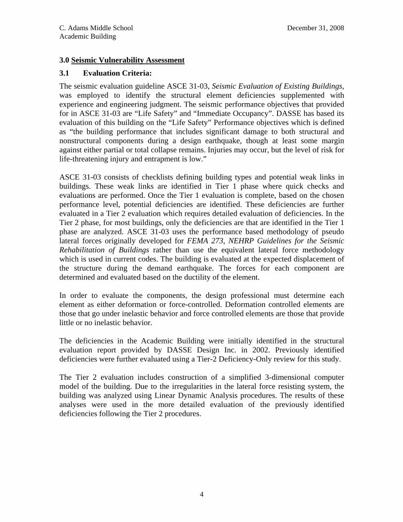
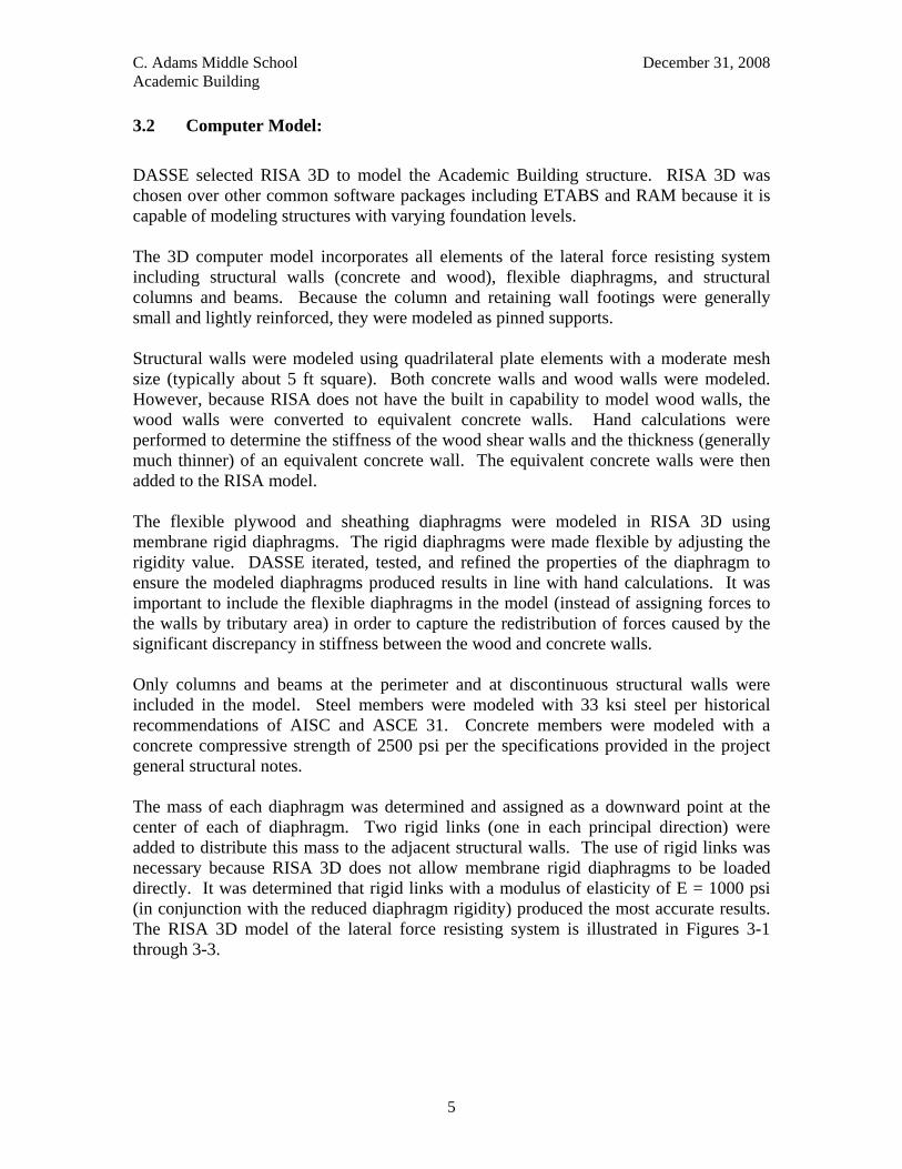
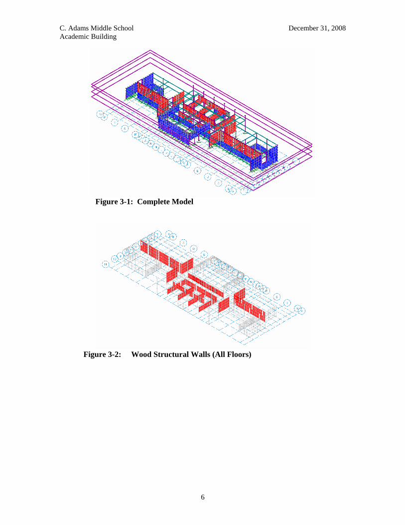
DASSE selected RISA 3D to model the Academic Building structure. RISA 3D was chosen over other common software packages including ETABS and RAM because it is capable of modeling structures with varying foundation levels. The 3D computer model incorporates all elements of the lateral force resisting system including structural walls (concrete and wood), flexible diaphragms, and structural columns and beams. Because the column and retaining wall footings were generally small and lightly reinforced, they were modeled as pinned supports. Structural walls were modeled using quadrilateral plate elements with a moderate mesh size (typically about 5 ft square). Both concrete walls and wood walls were modeled. However, because RISA does not have the built in capability to model wood walls, the wood walls were converted to equivalent concrete walls. Hand calculations were performed to determine the stiffness of the wood shear walls and the thickness (generally much thinner) of an equivalent concrete wall. The equivalent concrete walls were then added to the RISA model. The flexible plywood and sheathing diaphragms were modeled in RISA 3D using membrane rigid diaphragms. The rigid diaphragms were made flexible by adjusting the rigidity value. DASSE iterated, tested, and refined the properties of the diaphragm to ensure the modeled diaphragms produced results in line with hand calculations. It was important to include the flexible diaphragms in the model (instead of assigning forces to the walls by tributary area) in order to capture the redistribution of forces caused by the significant discrepancy in stiffness between the wood and concrete walls. Only columns and beams at the perimeter and at discontinuous structural walls were included in the model. Steel members were modeled with 33 ksi steel per historical recommendations of AISC and ASCE 31. Concrete members were modeled with a concrete compressive strength of 2500 psi per the specifications provided in the project general structural notes. The mass of each diaphragm was determined and assigned as a downward point at the center of each of diaphragm. Two rigid links (one in each principal direction) were added to distribute this mass to the adjacent structural walls. The use of rigid links was necessary because RISA 3D does not allow membrane rigid diaphragms to be loaded directly. It was determined that rigid links with a modulus of elasticity of E = 1000 psi (in conjunction with the reduced diaphragm rigidity) produced the most accurate results. The RISA 3D model of the lateral force resisting system is illustrated in Figures 3-1 through 3-3.
C. Adams Middle School December 31, 2008 Academic Building
6
Figure 3-1: Complete Model
Figure 3-2: Wood Structural Walls (All Floors)
C. Adams Middle School December 31, 2008 Academic Building
7
Figure 3-3: Concrete Structural Walls (All Floors)
C. Adams Middle School December 31, 2008 Academic Building
8
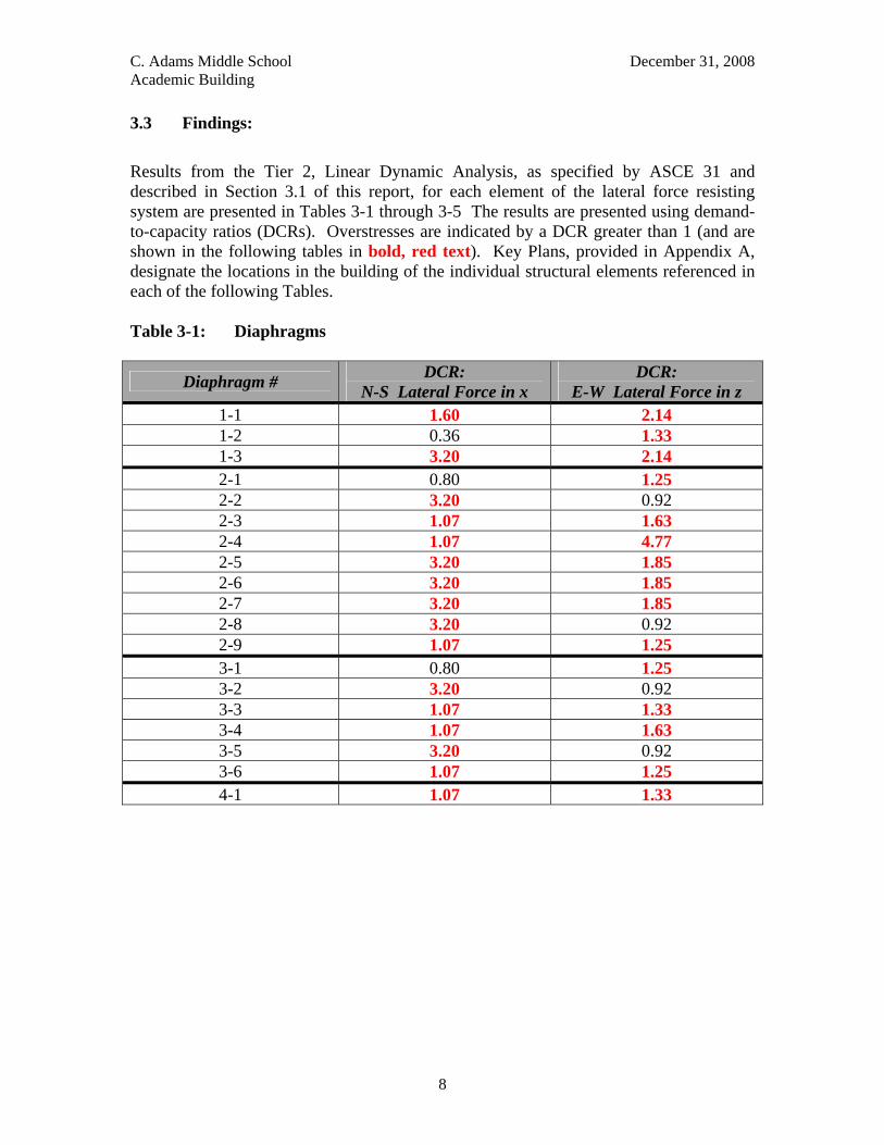
3.3 Findings: Results from the Tier 2, Linear Dynamic Analysis, as specified by ASCE 31 and described in Section 3.1 of this report, for each element of the lateral force resisting system are presented in Tables 3-1 through 3-5 The results are presented using demand-to-capacity ratios (DCRs). Overstresses are indicated by a DCR greater than 1 (and are shown in the following tables in bold, red text). Key Plans, provided in Appendix A, designate the locations in the building of the individual structural elements referenced in each of the following Tables. Table 3-1: Diaphragms
Diaphragm # DCR: N-S Lateral Force in x
DCR: E-W Lateral Force in z
1-1 1.60 2.14 1-2 0.36 1.33 1-3 3.20 2.14 2-1 0.80 1.25 2-2 3.20 0.92 2-3 1.07 1.63 2-4 1.07 4.77 2-5 3.20 1.85 2-6 3.20 1.85 2-7 3.20 1.85 2-8 3.20 0.92 2-9 1.07 1.25 3-1 0.80 1.25 3-2 3.20 0.92 3-3 1.07 1.33 3-4 1.07 1.63 3-5 3.20 0.92 3-6 1.07 1.25 4-1 1.07 1.33
C. Adams Middle School December 31, 2008 Academic Building
9
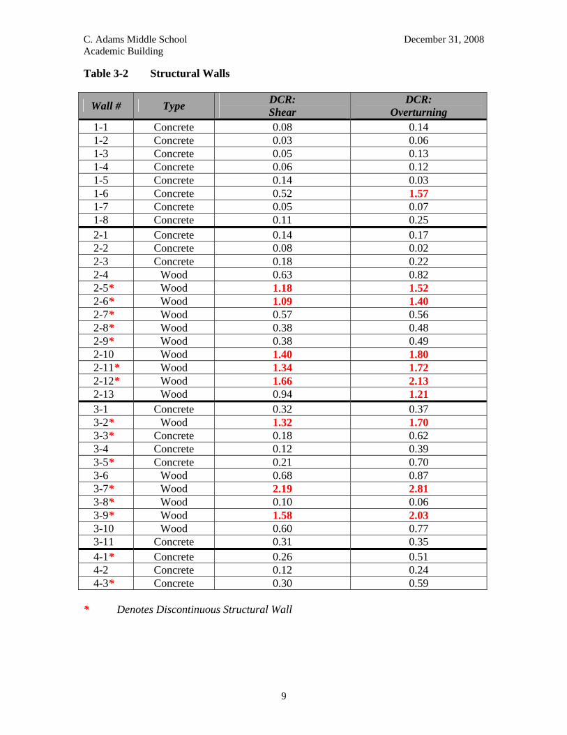
Table 3-2 Structural Walls
Wall # Type DCR: Shear
DCR: Overturning
1-1 Concrete 0.08 0.14 1-2 Concrete 0.03 0.06 1-3 Concrete 0.05 0.13 1-4 Concrete 0.06 0.12 1-5 Concrete 0.14 0.03 1-6 Concrete 0.52 1.57 1-7 Concrete 0.05 0.07 1-8 Concrete 0.11 0.25 2-1 Concrete 0.14 0.17 2-2 Concrete 0.08 0.02 2-3 Concrete 0.18 0.22 2-4 Wood 0.63 0.82 2-5* Wood 1.18 1.52 2-6* Wood 1.09 1.40 2-7* Wood 0.57 0.56 2-8* Wood 0.38 0.48 2-9* Wood 0.38 0.49 2-10 Wood 1.40 1.80 2-11* Wood 1.34 1.72 2-12* Wood 1.66 2.13 2-13 Wood 0.94 1.21 3-1 Concrete 0.32 0.37 3-2* Wood 1.32 1.70 3-3* Concrete 0.18 0.62 3-4 Concrete 0.12 0.39 3-5* Concrete 0.21 0.70 3-6 Wood 0.68 0.87 3-7* Wood 2.19 2.81 3-8* Wood 0.10 0.06 3-9* Wood 1.58 2.03 3-10 Wood 0.60 0.77 3-11 Concrete 0.31 0.35 4-1* Concrete 0.26 0.51 4-2 Concrete 0.12 0.24 4-3* Concrete 0.30 0.59
* Denotes Discontinuous Structural Wall
C. Adams Middle School December 31, 2008 Academic Building
10
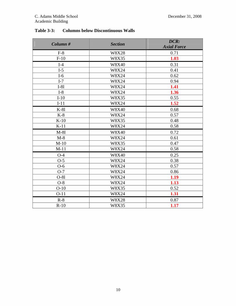
Table 3-3: Columns below Discontinuous Walls
Column # Section DCR: Axial Force
F-8 W8X28 0.71 F-10 W8X35 1.03 I-4 W8X40 0.31 I-5 W8X24 0.41 I-6 W8X24 0.62 I-7 W8X24 0.94 I-8l W8X24 1.41 I-8 W8X24 1.36 I-10 W8X35 0.55 I-11 W8X24 1.52 K-8l W8X40 0.68 K-8 W8X24 0.57 K-10 W8X35 0.48 K-11 W8X24 0.58 M-8l W8X40 0.72 M-8 W8X24 0.61 M-10 W8X35 0.47 M-11 W8X24 0.58 O-4 W8X40 0.25 O-5 W8X24 0.38 O-6 W8X24 0.57 O-7 W8X24 0.86 O-8l W8X24 1.19 O-8 W8X24 1.13 O-10 W8X35 0.52 O-11 W8X24 1.31 R-8 W8X28 0.87 R-10 W8X35 1.17
C. Adams Middle School December 31, 2008 Academic Building
11
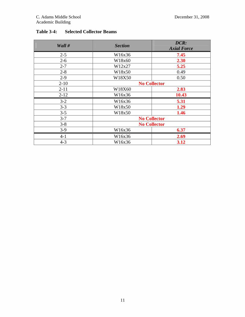
Table 3-4: Selected Collector Beams
Wall # Section DCR: Axial Force
2-5 W16x36 7.45 2-6 W18x60 2.30 2-7 W12x27 5.25 2-8 W18x50 0.49 2-9 W18X50 0.50 2-10 No Collector 2-11 W18X60 2.83 2-12 W16x36 10.43 3-2 W16x36 5.31 3-3 W18x50 1.29 3-5 W18x50 1.46 3-7 No Collector 3-8 No Collector 3-9 W16x36 6.37 4-1 W16x36 2.69 4-3 W16x36 3.12
C. Adams Middle School December 31, 2008 Academic Building
12
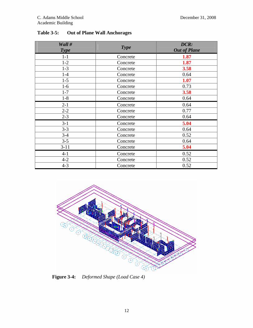
Table 3-5: Out of Plane Wall Anchorages
Wall # Type Type DCR:
Out of Plane 1-1 Concrete 1.87 1-2 Concrete 1.87 1-3 Concrete 3.58 1-4 Concrete 0.64 1-5 Concrete 1.07 1-6 Concrete 0.73 1-7 Concrete 3.58 1-8 Concrete 0.64 2-1 Concrete 0.64 2-2 Concrete 0.77 2-3 Concrete 0.64 3-1 Concrete 5.04 3-3 Concrete 0.64 3-4 Concrete 0.52 3-5 Concrete 0.64 3-11 Concrete 5.04 4-1 Concrete 0.52 4-2 Concrete 0.52 4-3 Concrete 0.52
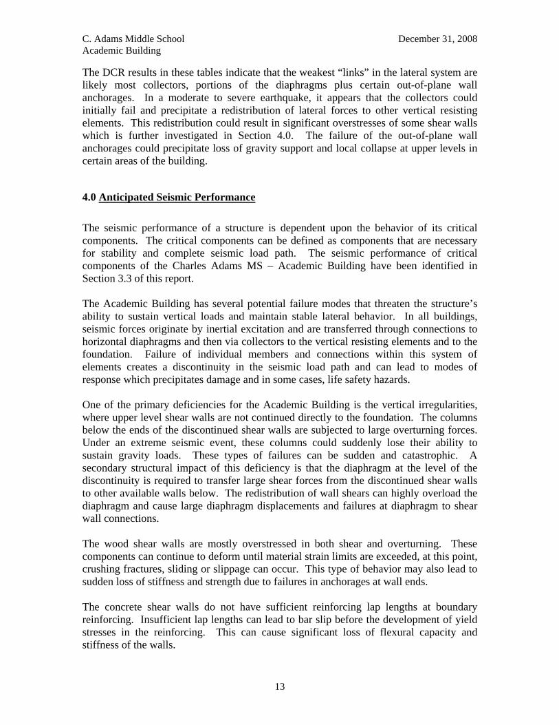
Figure 3-4: Deformed Shape (Load Case 4)
C. Adams Middle School December 31, 2008 Academic Building
13
The DCR results in these tables indicate that the weakest “links” in the lateral system are likely most collectors, portions of the diaphragms plus certain out-of-plane wall anchorages. In a moderate to severe earthquake, it appears that the collectors could initially fail and precipitate a redistribution of lateral forces to other vertical resisting elements. This redistribution could result in significant overstresses of some shear walls which is further investigated in Section 4.0. The failure of the out-of-plane wall anchorages could precipitate loss of gravity support and local collapse at upper levels in certain areas of the building.
4.0 Anticipated Seismic Performance The seismic performance of a structure is dependent upon the behavior of its critical components. The critical components can be defined as components that are necessary for stability and complete seismic load path. The seismic performance of critical components of the Charles Adams MS – Academic Building have been identified in Section 3.3 of this report. The Academic Building has several potential failure modes that threaten the structure’s ability to sustain vertical loads and maintain stable lateral behavior. In all buildings, seismic forces originate by inertial excitation and are transferred through connections to horizontal diaphragms and then via collectors to the vertical resisting elements and to the foundation. Failure of individual members and connections within this system of elements creates a discontinuity in the seismic load path and can lead to modes of response which precipitates damage and in some cases, life safety hazards. One of the primary deficiencies for the Academic Building is the vertical irregularities, where upper level shear walls are not continued directly to the foundation. The columns below the ends of the discontinued shear walls are subjected to large overturning forces. Under an extreme seismic event, these columns could suddenly lose their ability to sustain gravity loads. These types of failures can be sudden and catastrophic. A secondary structural impact of this deficiency is that the diaphragm at the level of the discontinuity is required to transfer large shear forces from the discontinued shear walls to other available walls below. The redistribution of wall shears can highly overload the diaphragm and cause large diaphragm displacements and failures at diaphragm to shear wall connections. The wood shear walls are mostly overstressed in both shear and overturning. These components can continue to deform until material strain limits are exceeded, at this point, crushing fractures, sliding or slippage can occur. This type of behavior may also lead to sudden loss of stiffness and strength due to failures in anchorages at wall ends. The concrete shear walls do not have sufficient reinforcing lap lengths at boundary reinforcing. Insufficient lap lengths can lead to bar slip before the development of yield stresses in the reinforcing. This can cause significant loss of flexural capacity and stiffness of the walls.
C. Adams Middle School December 31, 2008 Academic Building
14
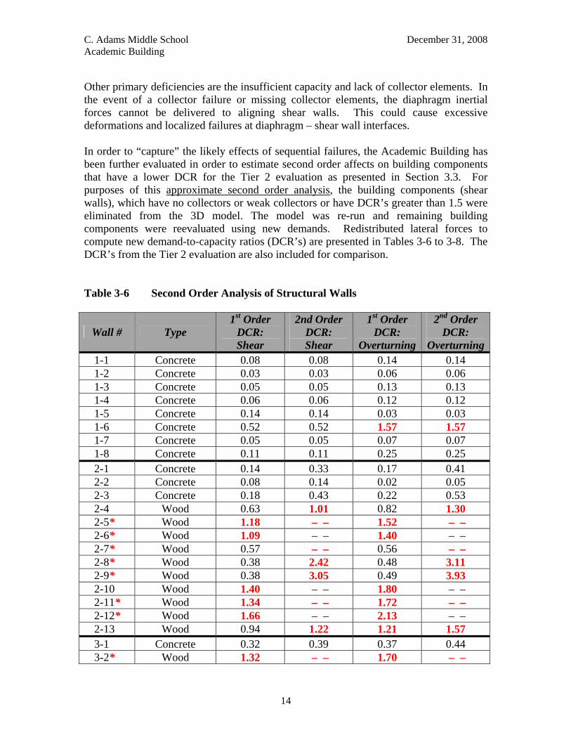
Other primary deficiencies are the insufficient capacity and lack of collector elements. In the event of a collector failure or missing collector elements, the diaphragm inertial forces cannot be delivered to aligning shear walls. This could cause excessive deformations and localized failures at diaphragm – shear wall interfaces. In order to “capture” the likely effects of sequential failures, the Academic Building has been further evaluated in order to estimate second order affects on building components that have a lower DCR for the Tier 2 evaluation as presented in Section 3.3. For purposes of this approximate second order analysis, the building components (shear walls), which have no collectors or weak collectors or have DCR’s greater than 1.5 were eliminated from the 3D model. The model was re-run and remaining building components were reevaluated using new demands. Redistributed lateral forces to compute new demand-to-capacity ratios (DCR’s) are presented in Tables 3-6 to 3-8. The DCR’s from the Tier 2 evaluation are also included for comparison. Table 3-6 Second Order Analysis of Structural Walls
Wall # Type 1st Order
DCR: Shear
2nd Order DCR: Shear
1st Order DCR:
Overturning
2nd Order DCR:
Overturning1-1 Concrete 0.08 0.08 0.14 0.14 1-2 Concrete 0.03 0.03 0.06 0.06 1-3 Concrete 0.05 0.05 0.13 0.13 1-4 Concrete 0.06 0.06 0.12 0.12 1-5 Concrete 0.14 0.14 0.03 0.03 1-6 Concrete 0.52 0.52 1.57 1.57 1-7 Concrete 0.05 0.05 0.07 0.07 1-8 Concrete 0.11 0.11 0.25 0.25 2-1 Concrete 0.14 0.33 0.17 0.41 2-2 Concrete 0.08 0.14 0.02 0.05 2-3 Concrete 0.18 0.43 0.22 0.53 2-4 Wood 0.63 1.01 0.82 1.30 2-5* Wood 1.18 – – 1.52 – – 2-6* Wood 1.09 – – 1.40 – – 2-7* Wood 0.57 – – 0.56 – – 2-8* Wood 0.38 2.42 0.48 3.11 2-9* Wood 0.38 3.05 0.49 3.93 2-10 Wood 1.40 – – 1.80 – – 2-11* Wood 1.34 – – 1.72 – – 2-12* Wood 1.66 – – 2.13 – – 2-13 Wood 0.94 1.22 1.21 1.57 3-1 Concrete 0.32 0.39 0.37 0.44 3-2* Wood 1.32 – – 1.70 – –
C. Adams Middle School December 31, 2008 Academic Building
15
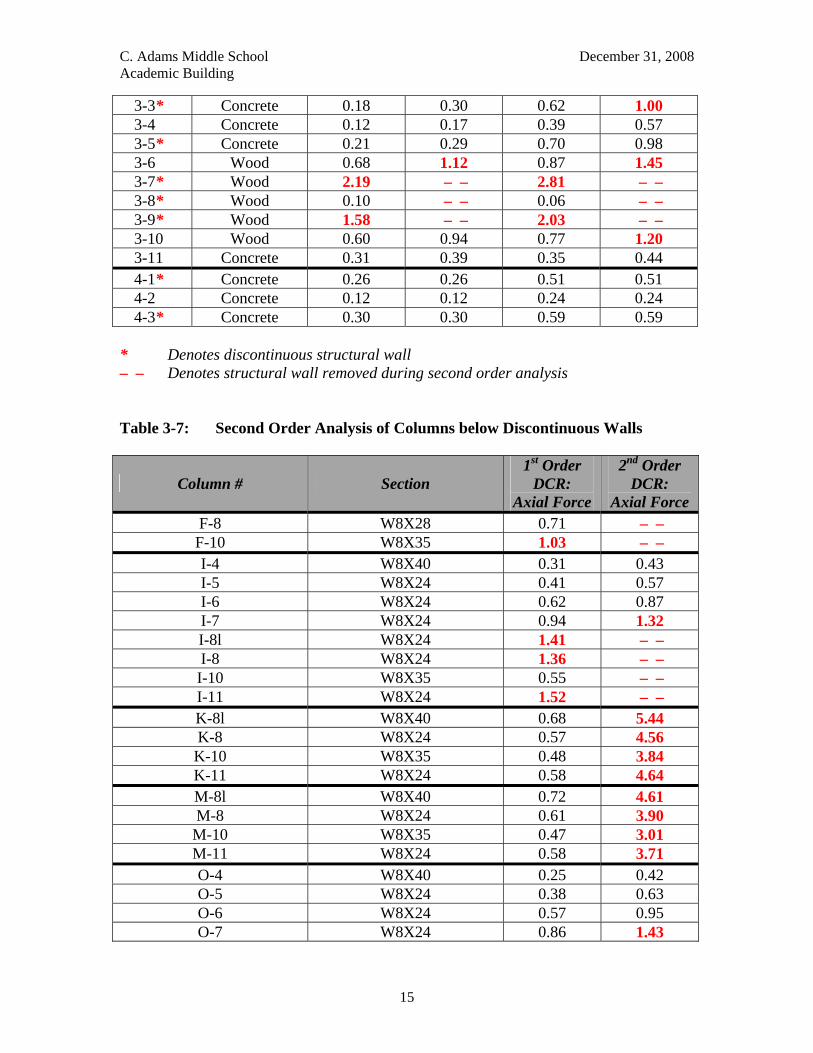
3-3* Concrete 0.18 0.30 0.62 1.00 3-4 Concrete 0.12 0.17 0.39 0.57 3-5* Concrete 0.21 0.29 0.70 0.98 3-6 Wood 0.68 1.12 0.87 1.45 3-7* Wood 2.19 – – 2.81 – – 3-8* Wood 0.10 – – 0.06 – – 3-9* Wood 1.58 – – 2.03 – – 3-10 Wood 0.60 0.94 0.77 1.20 3-11 Concrete 0.31 0.39 0.35 0.44 4-1* Concrete 0.26 0.26 0.51 0.51 4-2 Concrete 0.12 0.12 0.24 0.24 4-3* Concrete 0.30 0.30 0.59 0.59
* Denotes discontinuous structural wall – – Denotes structural wall removed during second order analysis Table 3-7: Second Order Analysis of Columns below Discontinuous Walls
Column # Section 1st Order
DCR: Axial Force
2nd Order DCR:
Axial Force F-8 W8X28 0.71 – – F-10 W8X35 1.03 – – I-4 W8X40 0.31 0.43 I-5 W8X24 0.41 0.57 I-6 W8X24 0.62 0.87 I-7 W8X24 0.94 1.32 I-8l W8X24 1.41 – – I-8 W8X24 1.36 – – I-10 W8X35 0.55 – – I-11 W8X24 1.52 – – K-8l W8X40 0.68 5.44 K-8 W8X24 0.57 4.56 K-10 W8X35 0.48 3.84 K-11 W8X24 0.58 4.64 M-8l W8X40 0.72 4.61 M-8 W8X24 0.61 3.90 M-10 W8X35 0.47 3.01 M-11 W8X24 0.58 3.71 O-4 W8X40 0.25 0.42 O-5 W8X24 0.38 0.63 O-6 W8X24 0.57 0.95 O-7 W8X24 0.86 1.43
C. Adams Middle School December 31, 2008 Academic Building
16
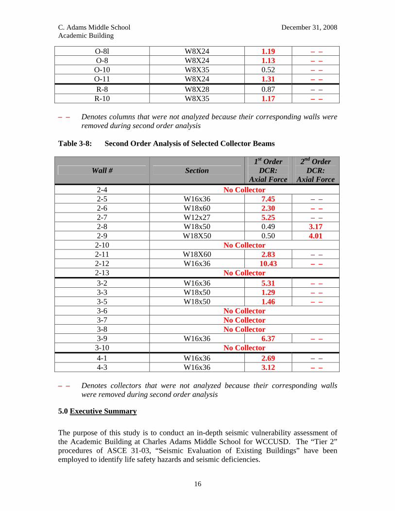
O-8l W8X24 1.19 – – O-8 W8X24 1.13 – – O-10 W8X35 0.52 – – O-11 W8X24 1.31 – – R-8 W8X28 0.87 – – R-10 W8X35 1.17 – –
– – Denotes columns that were not analyzed because their corresponding walls were
removed during second order analysis Table 3-8: Second Order Analysis of Selected Collector Beams
Wall # Section 1st Order
DCR: Axial Force
2nd Order DCR:
Axial Force 2-4 No Collector 2-5 W16x36 7.45 – – 2-6 W18x60 2.30 – – 2-7 W12x27 5.25 – – 2-8 W18x50 0.49 3.17 2-9 W18X50 0.50 4.01 2-10 No Collector 2-11 W18X60 2.83 – – 2-12 W16x36 10.43 – – 2-13 No Collector 3-2 W16x36 5.31 – – 3-3 W18x50 1.29 – – 3-5 W18x50 1.46 – – 3-6 No Collector 3-7 No Collector 3-8 No Collector 3-9 W16x36 6.37 – – 3-10 No Collector 4-1 W16x36 2.69 – – 4-3 W16x36 3.12 – –
– – Denotes collectors that were not analyzed because their corresponding walls
were removed during second order analysis
5.0 Executive Summary
The purpose of this study is to conduct an in-depth seismic vulnerability assessment of the Academic Building at Charles Adams Middle School for WCCUSD. The “Tier 2” procedures of ASCE 31-03, “Seismic Evaluation of Existing Buildings” have been employed to identify life safety hazards and seismic deficiencies.
C. Adams Middle School December 31, 2008 Academic Building
17
This report provides a description of the building and the structural features essential to this study, the detailed criteria and procedure employed, the computer model of the lateral force resisting system and the findings of this assessment. Also included are DASSE’s professional opinions as to how the Academic Building Structure will perform in a moderate to severe earthquake. The Academic Building which was reportedly designed per the 1955 Uniform Building Code is a 3 level, wood-steel-concrete “hybrid” which is “stepped” into the hillside. The floor and roof framings consist of wood joists plus steel beams and girders spanning to steel columns and concrete walls founded on shallow foundations. Lateral resistance is provided by horizontal thin plywood diaphragms distributing forces to concrete walls and plywood sheathed wood stud walls. Some of these walls are “discontinuous” and terminate over steel columns. The major identified deficiencies of the lateral force resisting system in order of severity are:
1. Lack of critical collector members and/or adequate “drag” connections to provide clear paths for transfer of diaphragm forces to shear walls.
2. Weak out-of-plane concrete wall anchorages. 3. Weak plywood diaphragms. 4. Discontinuous wood and concrete shear walls in critical locations. 5. Lack of adequate wood shear wall capacities at critical locations.
These deficiencies are expected to have significant impact on the performance of the building structure in a moderate to severe earthquake. In DASSE’s opinion, the structure could experience significant and likely irreparable damage in a moderate earthquake causing strong ground motion at the site. While safe exit of students and faculty may be unimpeded with some injuries, partial or localized collapse is not anticipated. In a severe earthquake with intense ground motion at the site, it is conceivable that these deficiencies will pose significant life safety hazards and localized collapse in several locations of the building is possible. In conclusion, DASSE recommends that this building be retrofitted to address these life safety hazards.
C. Adams Middle School December 31, 2008 Academic Building
A-1
APPENDIX A
KEY PLANS
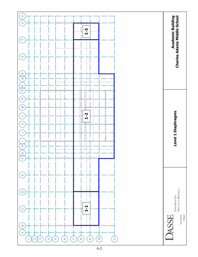
1-1
1-2
1-3
Level 1 Diaphragms
Academic Building
Charles Adams Middle School
A-2
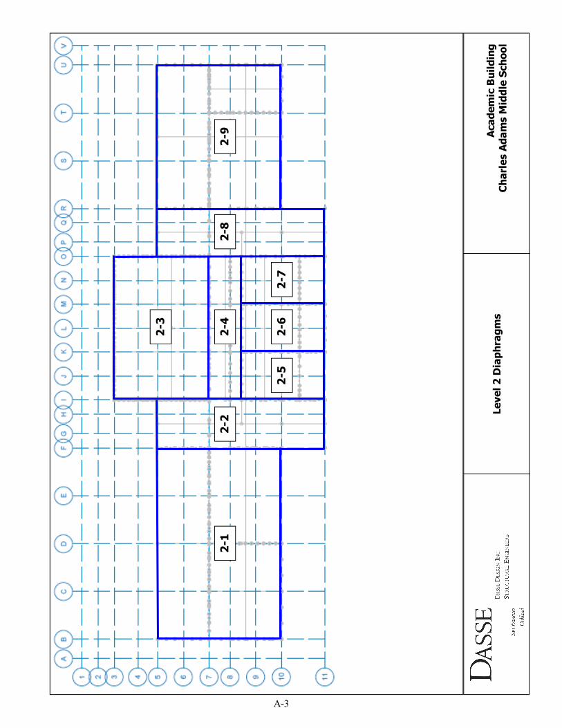
2-1
2-2
2-3
2-4
2-5
2-6
2-7
2-8
2-9
Level 2 Diaphragms
Academic Building
Charles Adams Middle School
A-3
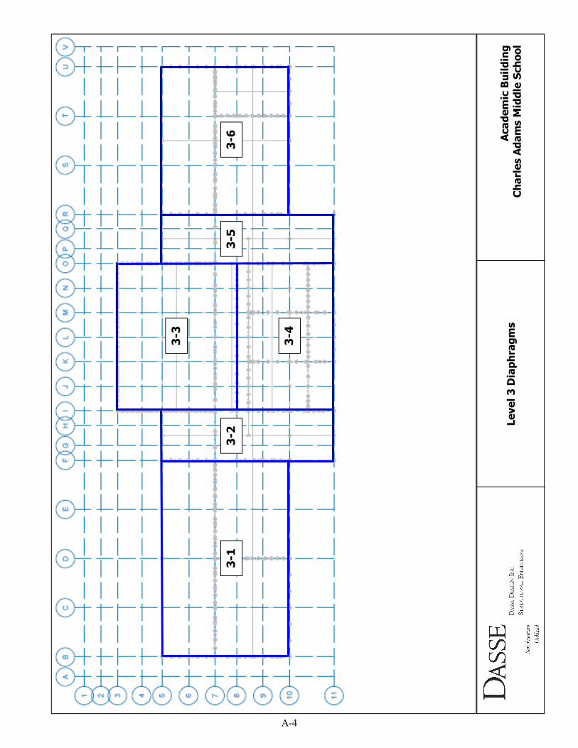
3-1
3-2
3-3
3-4
3-5
3-6
Level 3 Diaphragms
Academic Building
Charles Adams Middle School
A-4
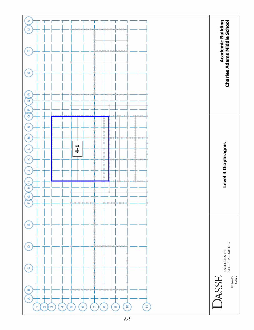
4-1
Level 4 Diaphragms
Academic Building
Charles Adams Middle School
A-5
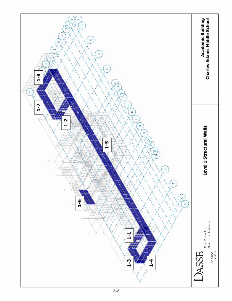
1-4
1-8
1-7
1-2
1-3
1-1
1-5
1-6
Level 1 Structural Walls
Academic Building
Charles Adams Middle School
A-6
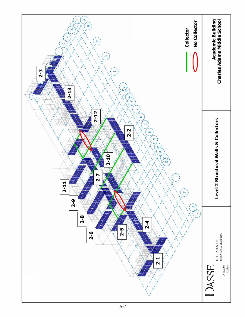
2-1
2-8
2-2
2-3
2-4
2-5
2-6
2-13
2-12
2-11
2-9
2-10
2-7
Collector
No Collector
Level 2 Structural Walls & Collectors
Academic Building
Charles Adams Middle School
A-7
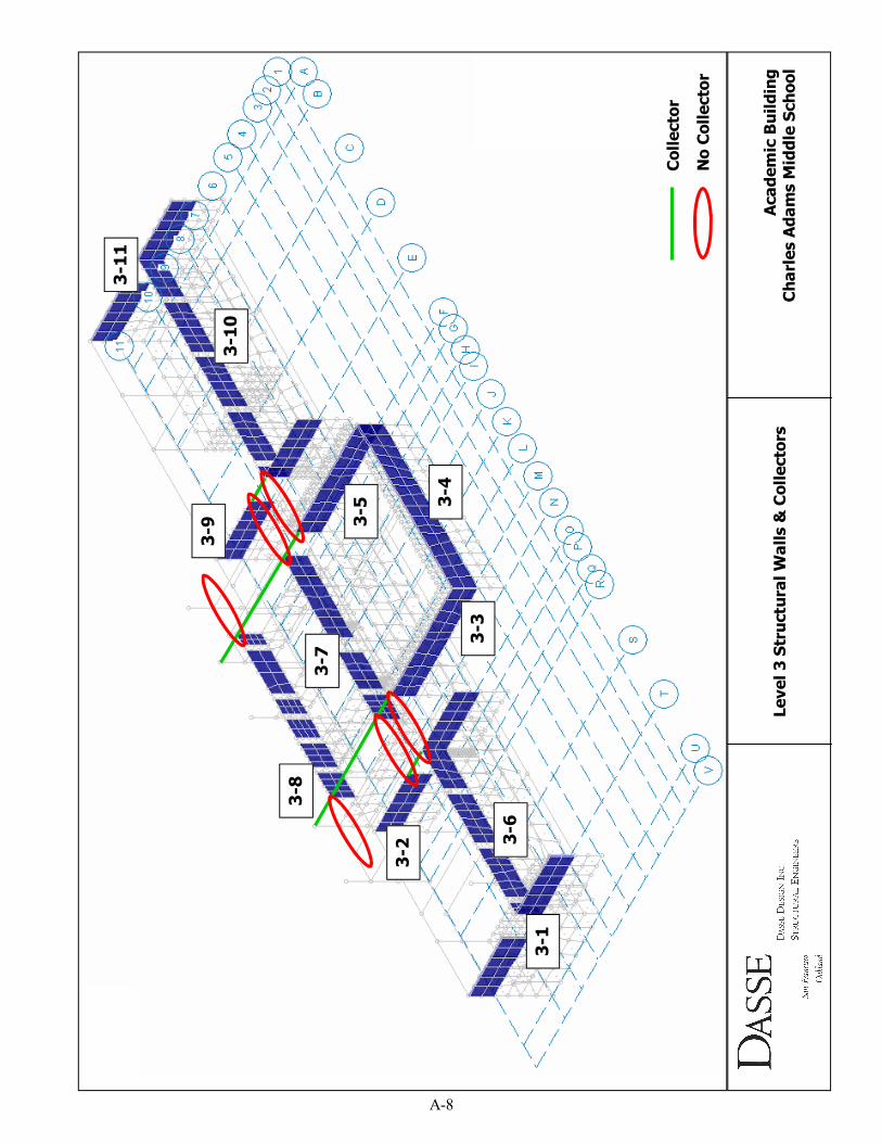
3-1
3-8
3-7
3-2
3-3
3-4
3-5
3-6
3-11
3-10
3-9
Level 3 Structural Walls & Collectors
Academic Building
Charles Adams Middle School
Collector
No Collector
A-8
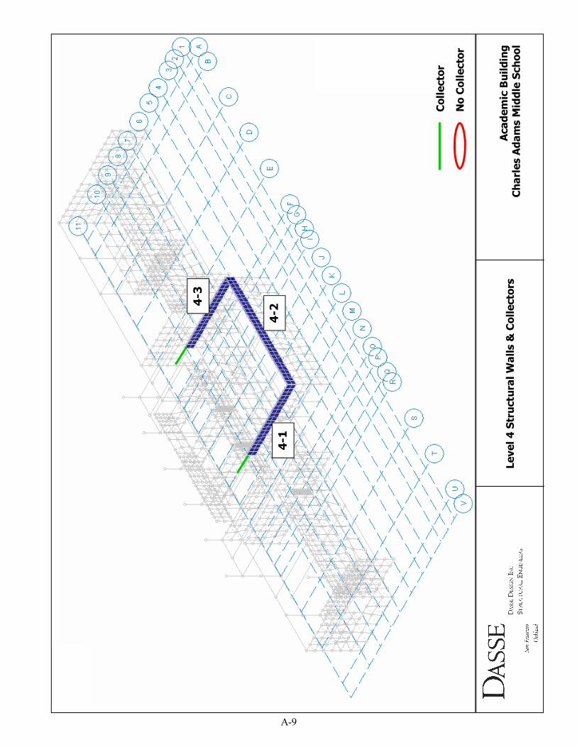
4-1
4-2 4-3
Level 4 Structural Walls & Collectors
Academic Building
Charles Adams Middle School
Collector
No Collector
A-9
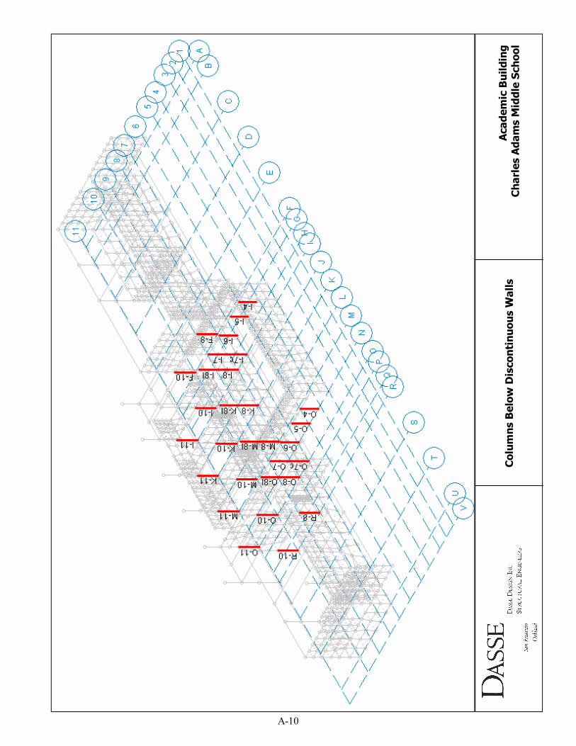
Columns Below Discontinuous W
alls
Academic Building
Charles Adams Middle School
A-10