Embed Size (px)
Citation preview
The Journal of the Anti-Seismic Systems International Society (ASSISi)
Seismic Isolation andProtection Systems
mathematical sciences publishers
AN EXPERIMENTAL MODEL OF BUCKLING RESTRAINEDBRACES
FOR MULTI-PERFORMANCE OPTIMUM DESIGN
Noemi Bonessio, Giuseppe Lomiento and Gianmario Benzoni
vol 2, no 1 2011
mathematical sciences publishers + Anti-Seismic Systems International SocietySEISMIC ISOLATION AND PROTECTION SYSTEMS 2:1 (2011)
AN EXPERIMENTAL MODEL OF BUCKLING RESTRAINED BRACESFOR MULTI-PERFORMANCE OPTIMUM DESIGN
NOEMI BONESSIO, GIUSEPPE LOMIENTO AND GIANMARIO BENZONI
This paper presents the formulation of an analytical model of buckling restrained braces (BRBs) and itsimplementation into a structural optimization procedure in order to design the protection system of anexisting structure. The procedure, based on a multi-performance approach, provides the minimum costdesign solution, through sizing and topology optimization of the BRBs, for the retrofit of an existingstructure. An analytical formulation for the BRBs is developed in order to introduce an efficient char-acterization of these devices into the structural optimization procedure. The prediction provided by theproposed analytical model is compared with the results of an experimental test campaign and the bilinearmodel.
1. Introduction
Passive energy dissipators such as viscous-fluid dampers, viscous-elastic dampers, metallic ductile dampersand friction dampers are widely used to reduce the dynamic response of civil engineering structures dueto seismic and wind loads. The effectiveness of the dampers depends on the capability to absorb thestructural vibration energy and to dissipate it through their inherent hysteresis behavior in order to reducestructural damages [Soong and Dargush 1997]. Among these dissipating devices, buckling restrainedbraces (BRBs) have been developed and applied for the seismic protection of building structures sincetheir hysteretic behavior could be kept stable for cyclic tensile and compressive loads and desirableyielding forces are easily obtained by sizing their inner steel core. In addition they offer consistentenergy dissipation capability and easy manufacturing, installation and maintenance [Black et al. 2002;Kiggins and Uang 2006; Lopez and Sabelli 2004; Sabelli 2001; Sabelli et al. 2003; Wada et al. 1998].The optimal mechanical characteristics of the dampers depend on the structural configuration in whichthey are located, on the performance level and on the entity of the applied horizontal loads. Sizing andtopology optimization procedures can be efficiently used in order to determine their characteristics andtheir location in a generic structural scheme.
Recently, performance-based design is getting more importance, overcoming traditional prescriptivedesign methods towards full reliability-based design methodologies. The present paper uses performance-based design concepts and casts them into a multiple-objective optimization procedure. In many studies,mono- or multi-optimization tools have been applied to the structural design [Frangopol 1995; Breitunget al. 1998; Thoft-Christensen and Sorensen 1987; Fu and Frangopol 1990]. In particular, the structuraloptimization procedure developed in [Bonessio 2010] has been here specialized into a specific procedureto retrofit an existing structure with a BRB system. The procedure provides the minimum cost design
Keywords: buckling restrained braces, experimental tests, analytical model, performance-based design, structuraloptimization.
75
76 NOEMI BONESSIO, GIUSEPPE LOMIENTO AND GIANMARIO BENZONI
solution through the optimization of the braces characteristics and locations on the structure, while re-specting several performance requirements. The proposed approach is based on a complete mechanicalrepresentation of the existing frame and the braces [Lomiento et al. 2010].
In many studies, the simple bilinear representation of the cyclic behavior of BRBs has shown tounderestimate their actual capacity in the small deformation range [Tremblay et al. 2004; Fahnestocket al. 2004]. More accurate models, generally used to perform nonlinear time history analyses, preventa closed-form definition of parameters commonly used in optimization procedures, such as effectivestiffness and damping. For the BRBs, an original mechanical model based on experimental data is hereproposed and formulated in a closed form to be easily integrated into the optimization algorithm.
2. Structural optimization procedure
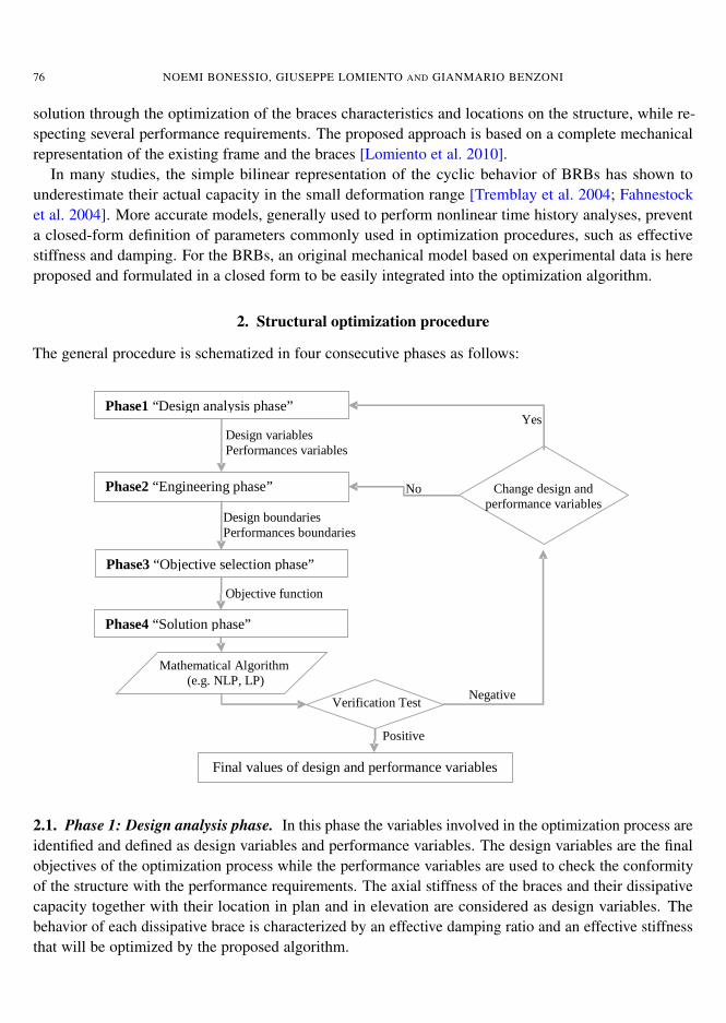
The general procedure is schematized in four consecutive phases as follows:
����������������������� ����
�
��������������������� ����
�
���������������������������� ����
���������������� ����
�� ������������ ��
�������� !"� !#�
$���%�������&����
'���������%�(�������(����%���������������
��������������
!��%���������������
�����������(�����
!��%������������(������
!��������
��������
)���
��� * ����(�������(�
���%���������������
����������%��������
�� �������� ����+������%�� �������(���
2.1. Phase 1: Design analysis phase. In this phase the variables involved in the optimization process areidentified and defined as design variables and performance variables. The design variables are the finalobjectives of the optimization process while the performance variables are used to check the conformityof the structure with the performance requirements. The axial stiffness of the braces and their dissipativecapacity together with their location in plan and in elevation are considered as design variables. Thebehavior of each dissipative brace is characterized by an effective damping ratio and an effective stiffnessthat will be optimized by the proposed algorithm.
BUCKLING RESTRAINED BRACES FOR MULTI-PERFORMANCE OPTIMUM DESIGN 77
The generic structural scheme consists in a three-dimensional structure with p floors (k = 1 . . . p) andm columns ( j = 1 . . .m) for a total of n = p(m− 1) structural bays, available to allocate the braces; thei-th brace (i = 1 . . . n) is located in the i-th structural bay, pinned or bolted to the frame.
The design variables to be optimized are stored in two vectors. The first one is the n× 1 vector k:
k = [k1 k2 . . . ki . . . kn]T (2-1)
where ki is the normalized axial stiffness of the i-th brace, given by:
ki =Ki
K refi
(2-2)
Ki is the axial stiffness of the i-th brace and K refi is the axial stiffness associated with a conventional
cross-sectional area used as a reference to initialize the procedure. The second n×1 vector ξ is defined as
ξ = [ξ1 ξ2 . . . ξi . . . ξn]T (2-3)
where ξi is the damping ratio of the i-th brace. The total stiffness matrix Ktot (k, ξ), condensed on thelateral displacement, and the total damping ratio of the structure ξtot (k, ξ) are considered as performancevariables. The performance variables need to be express as a function of the design vectors k and ξ inorder to be implemented in the optimization algorithm. These correlations are proposed by Bonessio,where parametric analyses on the global stiffness matrix and on the total damping have been performed[Bonessio 2010].
2.2. Phase 2: The engineering phase. Several engineering boundaries on design and performance vari-ables are set in the form of inequalities and equations. The design boundaries are expressed as
k = [k1 k2 . . . ki . . . kn]T≥ 0, (2-4)
ξ = [ξ1 ξ2 . . . ξi . . . ξn]T≥ 0, (2-5)
ξi = fi (ki ) for i = 1 . . . n. (2-6)
Equations (2-4) and (2-5) express a physical limitation on stiffness and damping ratio, valid for alltype of braces. The set of equations (2-6) is specific for the particular type of braces used and representsthe correlation between effective stiffness and damping ratio, as formulated in the next paragraph forthe BRBs. The accuracy of the mechanical model of the braces influences the optimum values of thedesign variables and consequently the efficiency of the earthquake protection system. The performanceboundaries are inequalities that involve the performance variables Ktot (k, ξ) and ξtot (k, ξ):
p ≤ Ktot (k, ξ) · u, (2-7)
ξtot (k, ξ)≤ ξtot (2-8)
where p is a vector of assigned lateral loads, for each performance level, u is the vector of the maximumallowable displacements, and ξtot is the maximum allowed damping ratio.
78 NOEMI BONESSIO, GIUSEPPE LOMIENTO AND GIANMARIO BENZONI
2.3. Phase 3: The objective selection phase. The definition of the objective of the design procedurerepresents the goal of this phase. For this application the objective is the cost-minimization of the protec-tion system. The cost W of the system is mainly associated with the size of the braces and consequentlyrelated to their stiffness:
W (k)= cT k (2-9)
where the vector cT= [c1 c2 . . . ci . . . cn] includes information about the geometry and the material
properties of the braces.
2.4. Phase 4: The solution phase. The final phase consists of the evaluation of the optimal numericalvalues for the design variables. For instance, for the sizing and topology optimization of a BRB protectionsystem, a standard nonlinear programming (NLP) problem has to be solved. The sequential solutiontechnique is proposed as a tool to treat the NLP problem as a linear programming problem [Bonessio2010]. The generic formulation of the problem, in agreement with the classical format of mathematicalprogramming, is expressed as follows, using equations (2-1) to (2-9):
Find k1, k2, . . . kn and ξ1, ξ2, . . . ξn
minimizing W (k)= cT k
subject to k ≥ 0,ξ ≥ 0,p ≤ Ktot(k, ξ) · u,ξ1 = f1(k1), . . . , ξn = fn(kn).
(2-10)
The procedure is able to determine the stiffness ki and the damping ratio ξi of the brace placed in thei-th location of the frame, for a maximum of n braces in the n possible locations. In the allowable set ofvalues for each design variable ki , zero values is also included. This allows some of the n braces to beeliminated so topology of the protection system can also be optimized.
3. Experimental characterization
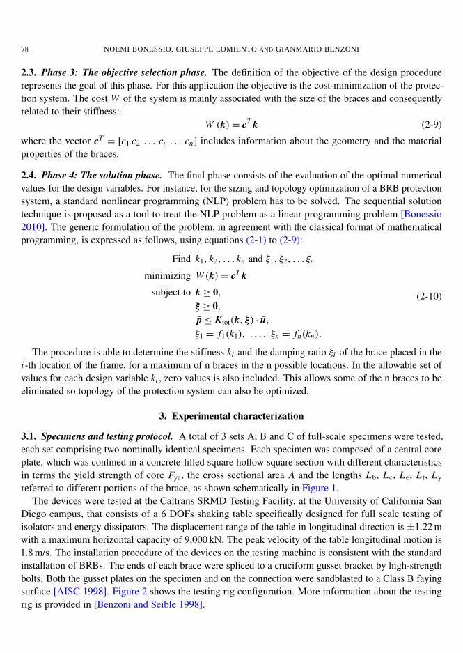
3.1. Specimens and testing protocol. A total of 3 sets A, B and C of full-scale specimens were tested,each set comprising two nominally identical specimens. Each specimen was composed of a central coreplate, which was confined in a concrete-filled square hollow square section with different characteristicsin terms the yield strength of core Fya, the cross sectional area A and the lengths Lb, Lc, Le, L t, Ly
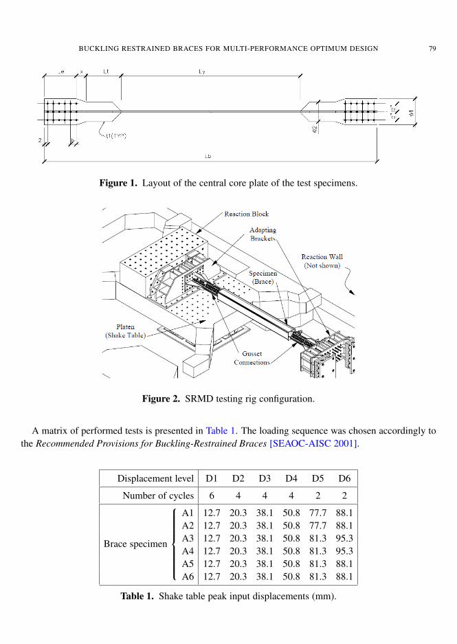
referred to different portions of the brace, as shown schematically in Figure 1.The devices were tested at the Caltrans SRMD Testing Facility, at the University of California San
Diego campus, that consists of a 6 DOFs shaking table specifically designed for full scale testing ofisolators and energy dissipators. The displacement range of the table in longitudinal direction is ±1.22 mwith a maximum horizontal capacity of 9,000 kN. The peak velocity of the table longitudinal motion is1.8 m/s. The installation procedure of the devices on the testing machine is consistent with the standardinstallation of BRBs. The ends of each brace were spliced to a cruciform gusset bracket by high-strengthbolts. Both the gusset plates on the specimen and on the connection were sandblasted to a Class B fayingsurface [AISC 1998]. Figure 2 shows the testing rig configuration. More information about the testingrig is provided in [Benzoni and Seible 1998].
BUCKLING RESTRAINED BRACES FOR MULTI-PERFORMANCE OPTIMUM DESIGN 79
�� �������� ����+������%�� �������(���
�� ������ ������%�� ����������������Figure 1. Layout of the central core plate of the test specimens.
�� �������,������������������%��������Figure 2. SRMD testing rig configuration.
A matrix of performed tests is presented in Table 1. The loading sequence was chosen accordingly tothe Recommended Provisions for Buckling-Restrained Braces [SEAOC-AISC 2001].
Displacement level D1 D2 D3 D4 D5 D6
Number of cycles 6 4 4 4 2 2
A1 12.7 20.3 38.1 50.8 77.7 88.1A2 12.7 20.3 38.1 50.8 77.7 88.1
Brace specimen
A3 12.7 20.3 38.1 50.8 81.3 95.3A4 12.7 20.3 38.1 50.8 81.3 95.3A5 12.7 20.3 38.1 50.8 81.3 88.1A6 12.7 20.3 38.1 50.8 81.3 88.1
Table 1. Shake table peak input displacements (mm).
80 NOEMI BONESSIO, GIUSEPPE LOMIENTO AND GIANMARIO BENZONI
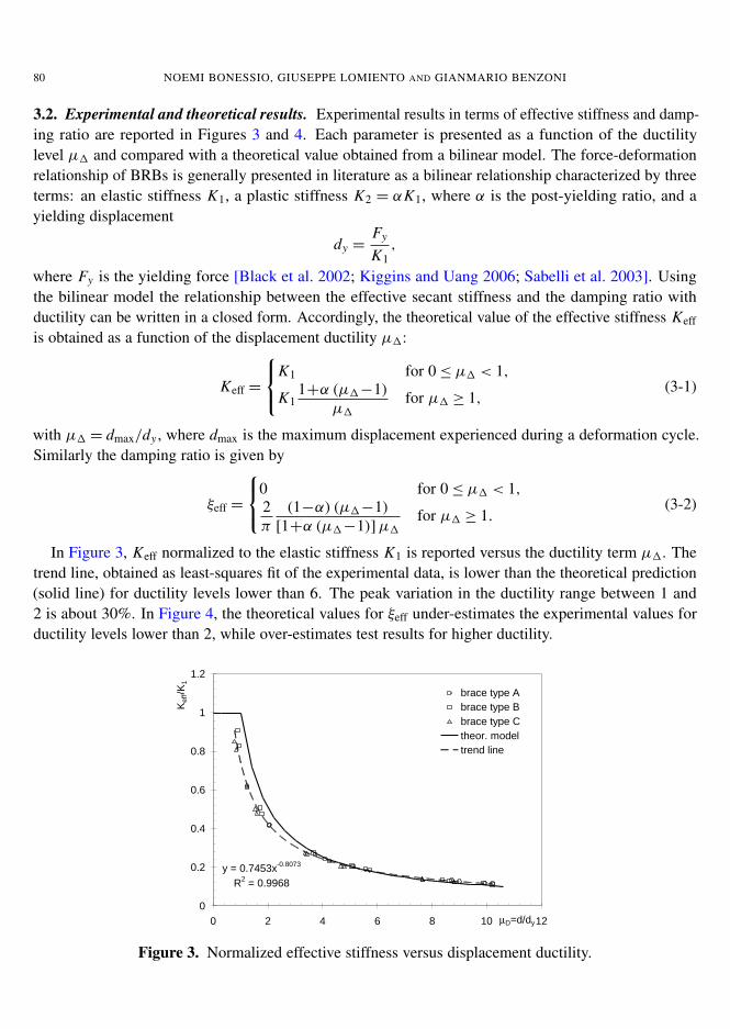
3.2. Experimental and theoretical results. Experimental results in terms of effective stiffness and damp-ing ratio are reported in Figures 3 and 4. Each parameter is presented as a function of the ductilitylevel µ1 and compared with a theoretical value obtained from a bilinear model. The force-deformationrelationship of BRBs is generally presented in literature as a bilinear relationship characterized by threeterms: an elastic stiffness K1, a plastic stiffness K2 = αK1, where α is the post-yielding ratio, and ayielding displacement
dy =Fy
K1,
where Fy is the yielding force [Black et al. 2002; Kiggins and Uang 2006; Sabelli et al. 2003]. Usingthe bilinear model the relationship between the effective secant stiffness and the damping ratio withductility can be written in a closed form. Accordingly, the theoretical value of the effective stiffness Keff
is obtained as a function of the displacement ductility µ1:
Keff =
K1 for 0≤ µ1 < 1,
K11+α (µ1−1)
µ1for µ1 ≥ 1,
(3-1)
with µ1 = dmax/dy , where dmax is the maximum displacement experienced during a deformation cycle.Similarly the damping ratio is given by
ξeff =
0 for 0≤ µ1 < 1,2π
(1−α) (µ1−1)[1+α (µ1−1)]µ1
for µ1 ≥ 1.(3-2)
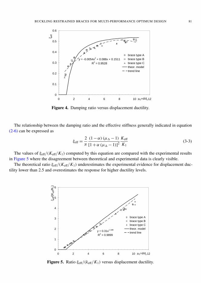
In Figure 3, Keff normalized to the elastic stiffness K1 is reported versus the ductility term µ1. Thetrend line, obtained as least-squares fit of the experimental data, is lower than the theoretical prediction(solid line) for ductility levels lower than 6. The peak variation in the ductility range between 1 and2 is about 30%. In Figure 4, the theoretical values for ξeff under-estimates the experimental values forductility levels lower than 2, while over-estimates test results for higher ductility.
���������������
����������
�
���
���
���
���
�
���
� � � � � �� ��µ������
�������
������������
������������
�����������
�!�"���#"��$
���%��$&%�
�� ����������+�(��%%����������%%������������(����������(�����
������
���
����
Figure 3. Normalized effective stiffness versus displacement ductility.
BUCKLING RESTRAINED BRACES FOR MULTI-PERFORMANCE OPTIMUM DESIGN 81
�������������'�������'�������
����������
�
���
���
��
���
���
���
� � � � � �� ��µ������
��
������������
������������
�����������
�!�"���#"��$
���%��$&%�
�� �������������������������(����������(�������Figure 4. Damping ratio versus displacement ductility.
The relationship between the damping ratio and the effective stiffness generally indicated in equation(2-6) can be expressed as
ξeff =2π
(1−α) (µ1− 1)
[1+α (µ1− 1)]2
Keff
K1(3-3)
The values of ξeff/(Keff/K1) computed by this equation are compared with the experimental resultsin Figure 5 where the disagreement between theoretical and experimental data is clearly visible.
The theoretical ratio ξeff/(Keff/K1) underestimates the experimental evidence for displacement duc-tility lower than 2.5 and overestimates the response for higher ductility levels.
������������
����������
�
�
�
�
�
�
� � � � � �� ��µ������
���(�������)
������������
������������
�����������
�!�"���#"��$
���%��$&%�
�� ������,���� -�� -� #��������(����������(�������
�����(#
Figure 5. Ratio ξeff/(keff/K1) versus displacement ductility.
82 NOEMI BONESSIO, GIUSEPPE LOMIENTO AND GIANMARIO BENZONI
4. Discussion of experimental results and proposed model
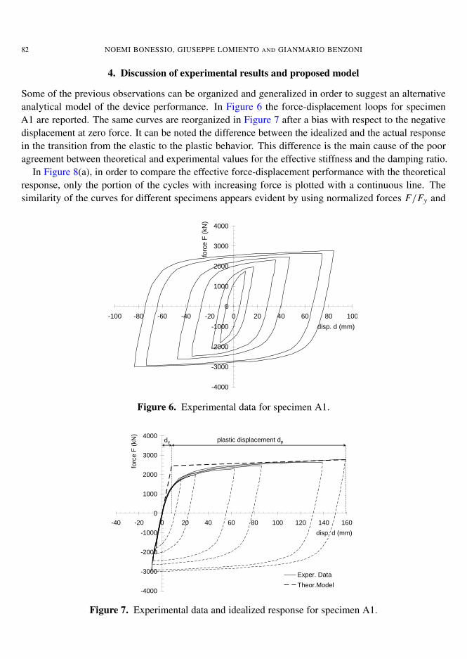
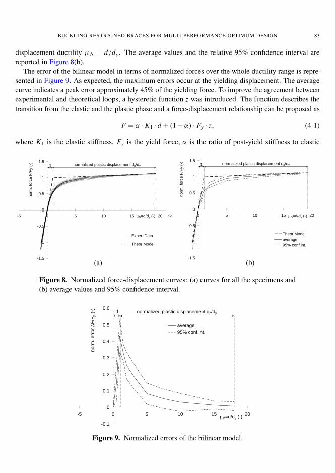
Some of the previous observations can be organized and generalized in order to suggest an alternativeanalytical model of the device performance. In Figure 6 the force-displacement loops for specimenA1 are reported. The same curves are reorganized in Figure 7 after a bias with respect to the negativedisplacement at zero force. It can be noted the difference between the idealized and the actual responsein the transition from the elastic to the plastic behavior. This difference is the main cause of the pooragreement between theoretical and experimental values for the effective stiffness and the damping ratio.
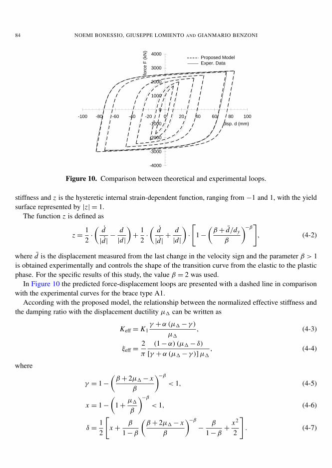
In Figure 8(a), in order to compare the effective force-displacement performance with the theoreticalresponse, only the portion of the cycles with increasing force is plotted with a continuous line. Thesimilarity of the curves for different specimens appears evident by using normalized forces F/Fy and
�� ������,���� -�� -� #��������(����������(�������
�����
����
�����
�����
�
����
����
���
����
���� ��� ��� ��� ��� � �� �� �� �� ���
�&*�����(##)
�"��
��+
�(,-)
��� �������.���������(��%�������������/Figure 6. Experimental data for specimen A1.
�����
����
�����
�����
�
����
����
���
����
��� ��� � �� �� �� �� ��� ��� ��� ���
�&*�����(##)
�"��
��+
�(,-)
.���������
/!�"��0"��$
�$�*�&���&*�$���#�%������
�� �������.���������(���(��(��+�(����������%�������������/
�(�)
���
Figure 7. Experimental data and idealized response for specimen A1.
BUCKLING RESTRAINED BRACES FOR MULTI-PERFORMANCE OPTIMUM DESIGN 83
displacement ductility µ1 = d/dy . The average values and the relative 95% confidence interval arereported in Figure 8(b).
The error of the bilinear model in terms of normalized forces over the whole ductility range is repre-sented in Figure 9. As expected, the maximum errors occur at the yielding displacement. The averagecurve indicates a peak error approximately 45% of the yielding force. To improve the agreement betweenexperimental and theoretical loops, a hysteretic function z was introduced. The function describes thetransition from the elastic and the plastic phase and a force-displacement relationship can be proposed as
F = α · K1 · d + (1−α) · Fy · z, (4-1)
where K1 is the elastic stiffness, Fy is the yield force, α is the ratio of post-yield stiffness to elastic
�� �������.���������(���(��(��+�(����������%�������������/
����
��
����
�
���
�
���
�� � � �� �� ��µ�������(�)
%"�#
���"
����+
�+��(�)
.���������
/!�"��0"��$
%"�#�$&1����$�*�&���&*�$���#�%��������
�� �����������+�(�%����0(�����������������%����� �����������
����
��
����
�
���
�
���
�� � � �� �� ��µ�������(�)
%"�#
���"
����+
�+��(�)
/!�"��0"��$
�2���3�
��4��"%��&%��
%"�#�$&1����$�*�&���&*�$���#�%��������
�����������+�(�%����0(����������������1�������������(�234����%�
�(�)
����
(a) (b)
Figure 8. Normalized force-displacement curves: (a) curves for all the specimens and(b) average values and 95% confidence interval.
����
�
���
���
��
���
���
���
�� � � �� �� ��µ�������(�)
%"�#
�����"��
∆+�+
��(�)
�2���3�
��4��"%��&%��
%"�#�$&1����$�*�&���&*�$���#�%���������
�� ������������+�(���������%�� �����������(�Figure 9. Normalized errors of the bilinear model.
84 NOEMI BONESSIO, GIUSEPPE LOMIENTO AND GIANMARIO BENZONI
�����
����
�����
�����
�
����
����
���
����
���� ��� ��� ��� ��� � �� �� �� �� ���
�&*�����(##)
�"��
��+
�(,-)
5�"�"*���0"��$
.���������
�� �������*������������5����� ���������(��.�������������
�
��
����
Figure 10. Comparison between theoretical and experimental loops.
stiffness and z is the hysteretic internal strain-dependent function, ranging from −1 and 1, with the yieldsurface represented by |z| = 1.
The function z is defined as
z =12·
(d|d|−
d|d|
)+
12·
(d|d|+
d|d|
)·
[1−
(β + d/dy
β
)−β], (4-2)
where d is the displacement measured from the last change in the velocity sign and the parameter β > 1is obtained experimentally and controls the shape of the transition curve from the elastic to the plasticphase. For the specific results of this study, the value β = 2 was used.
In Figure 10 the predicted force-displacement loops are presented with a dashed line in comparisonwith the experimental curves for the brace type A1.
According with the proposed model, the relationship between the normalized effective stiffness andthe damping ratio with the displacement ductility µ1 can be written as
Keff = K1γ +α (µ1− γ )
µ1, (4-3)
ξeff =2π
(1−α) (µ1− δ)[γ +α (µ1− γ )]µ1
, (4-4)
where
γ = 1−(β + 2µ1− x
β
)−β< 1, (4-5)
x = 1−(
1+µ1
β
)−β< 1, (4-6)
δ =12
[x +
β
1−β
(β + 2µ1− x
β
)−β−
β
1−β+
x2
2
]. (4-7)
BUCKLING RESTRAINED BRACES FOR MULTI-PERFORMANCE OPTIMUM DESIGN 85
���������������
����������
�
���
���
���
���
�
���
� � � � � �� ��µ������
�������
������������
������������
�����������
�!�"���#"��$
���%��$&%�
�� ������������+�(��%%����������%%������������(����������(�������Figure 11. Normalized effective stiffness versus displacement ductility from experimen-tal data and proposed model.
�������������'�������'�������
����������
�
���
���
��
���
���
���
� � � � � �� ��µ������
��
������������
������������
�����������
��"�"*���#"��$
���%��$&%�
�������������������������(����������(��������%�����.��������
��
��
��
Figure 12. Damping ratio versus displacement ductility from experimental data andproposed model.
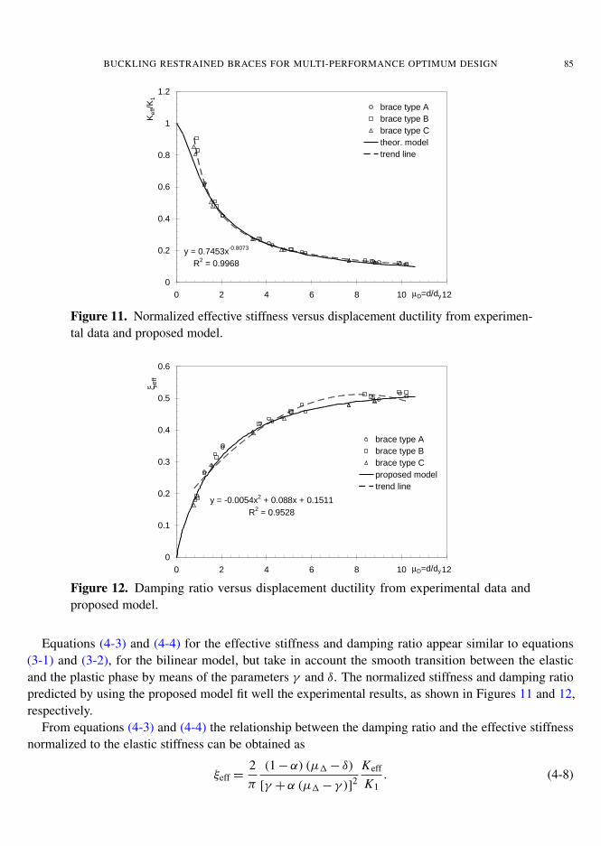
Equations (4-3) and (4-4) for the effective stiffness and damping ratio appear similar to equations(3-1) and (3-2), for the bilinear model, but take in account the smooth transition between the elasticand the plastic phase by means of the parameters γ and δ. The normalized stiffness and damping ratiopredicted by using the proposed model fit well the experimental results, as shown in Figures 11 and 12,respectively.
From equations (4-3) and (4-4) the relationship between the damping ratio and the effective stiffnessnormalized to the elastic stiffness can be obtained as
ξeff =2π
(1−α) (µ1− δ)
[γ +α (µ1− γ )]2
Keff
K1. (4-8)
86 NOEMI BONESSIO, GIUSEPPE LOMIENTO AND GIANMARIO BENZONI
������������
����������
�
�
�
�
�
�
� � � � � �� ��µ������
ξ ����(�������)
������������
������������
�����������
�!�"���#"��$
���%��$&%�
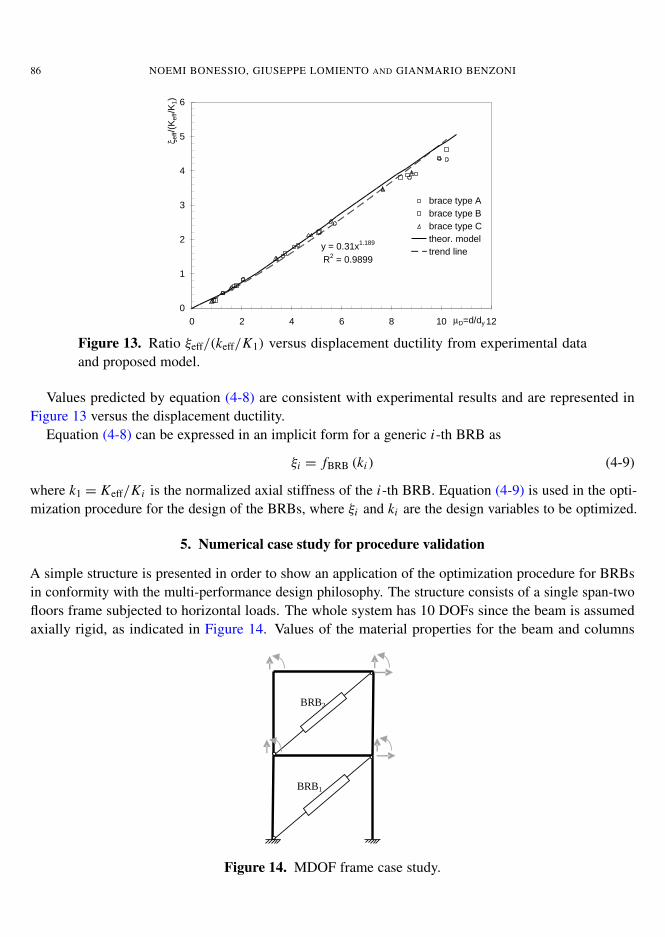
�� �������,���� -�� -� #��������(����������(�������Figure 13. Ratio ξeff/(keff/K1) versus displacement ductility from experimental dataand proposed model.
Values predicted by equation (4-8) are consistent with experimental results and are represented inFigure 13 versus the displacement ductility.
Equation (4-8) can be expressed in an implicit form for a generic i-th BRB as
ξi = fBRB (ki ) (4-9)
where k1 = Keff/Ki is the normalized axial stiffness of the i-th BRB. Equation (4-9) is used in the opti-mization procedure for the design of the BRBs, where ξi and ki are the design variables to be optimized.
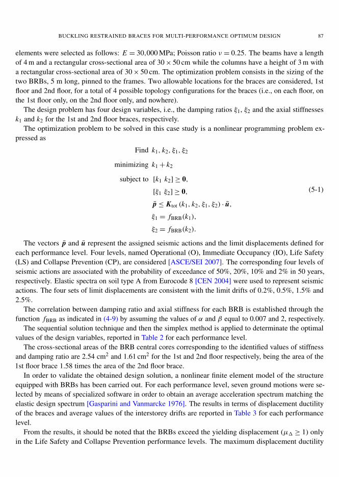
5. Numerical case study for procedure validation
A simple structure is presented in order to show an application of the optimization procedure for BRBsin conformity with the multi-performance design philosophy. The structure consists of a single span-twofloors frame subjected to horizontal loads. The whole system has 10 DOFs since the beam is assumedaxially rigid, as indicated in Figure 14. Values of the material properties for the beam and columns
�
6,67�
6,6/�
����������'�%���������
Figure 14. MDOF frame case study.
BUCKLING RESTRAINED BRACES FOR MULTI-PERFORMANCE OPTIMUM DESIGN 87
elements were selected as follows: E = 30,000 MPa; Poisson ratio ν = 0.25. The beams have a lengthof 4 m and a rectangular cross-sectional area of 30× 50 cm while the columns have a height of 3 m witha rectangular cross-sectional area of 30× 50 cm. The optimization problem consists in the sizing of thetwo BRBs, 5 m long, pinned to the frames. Two allowable locations for the braces are considered, 1stfloor and 2nd floor, for a total of 4 possible topology configurations for the braces (i.e., on each floor, onthe 1st floor only, on the 2nd floor only, and nowhere).
The design problem has four design variables, i.e., the damping ratios ξ1, ξ2 and the axial stiffnessesk1 and k2 for the 1st and 2nd floor braces, respectively.
The optimization problem to be solved in this case study is a nonlinear programming problem ex-pressed as
Find k1, k2, ξ1, ξ2
minimizing k1+ k2
subject to [k1 k2]≥ 0,
[ξ1 ξ2]≥ 0,
p ≤ Ktot (k1, k2, ξ1, ξ2) · u,
ξ1 = fBRB(k1),
ξ2 = fBRB(k2).
(5-1)
The vectors p and u represent the assigned seismic actions and the limit displacements defined foreach performance level. Four levels, named Operational (O), Immediate Occupancy (IO), Life Safety(LS) and Collapse Prevention (CP), are considered [ASCE/SEI 2007]. The corresponding four levels ofseismic actions are associated with the probability of exceedance of 50%, 20%, 10% and 2% in 50 years,respectively. Elastic spectra on soil type A from Eurocode 8 [CEN 2004] were used to represent seismicactions. The four sets of limit displacements are consistent with the limit drifts of 0.2%, 0.5%, 1.5% and2.5%.
The correlation between damping ratio and axial stiffness for each BRB is established through thefunction fBRB as indicated in (4-9) by assuming the values of α and β equal to 0.007 and 2, respectively.
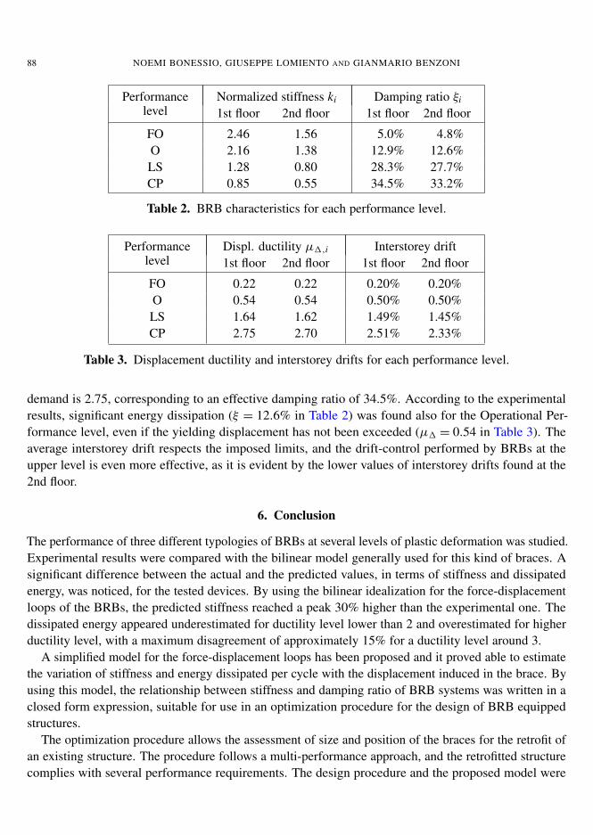
The sequential solution technique and then the simplex method is applied to determinate the optimalvalues of the design variables, reported in Table 2 for each performance level.
The cross-sectional areas of the BRB central cores corresponding to the identified values of stiffnessand damping ratio are 2.54 cm2 and 1.61 cm2 for the 1st and 2nd floor respectively, being the area of the1st floor brace 1.58 times the area of the 2nd floor brace.
In order to validate the obtained design solution, a nonlinear finite element model of the structureequipped with BRBs has been carried out. For each performance level, seven ground motions were se-lected by means of specialized software in order to obtain an average acceleration spectrum matching theelastic design spectrum [Gasparini and Vanmarcke 1976]. The results in terms of displacement ductilityof the braces and average values of the interstorey drifts are reported in Table 3 for each performancelevel.
From the results, it should be noted that the BRBs exceed the yielding displacement (µ1 ≥ 1) onlyin the Life Safety and Collapse Prevention performance levels. The maximum displacement ductility
88 NOEMI BONESSIO, GIUSEPPE LOMIENTO AND GIANMARIO BENZONI
Performance Normalized stiffness ki Damping ratio ξilevel 1st floor 2nd floor 1st floor 2nd floor
FO 2.46 1.56 5.0% 4.8%O 2.16 1.38 12.9% 12.6%LS 1.28 0.80 28.3% 27.7%CP 0.85 0.55 34.5% 33.2%
Table 2. BRB characteristics for each performance level.
Performance Displ. ductility µ1,i Interstorey driftlevel 1st floor 2nd floor 1st floor 2nd floor
FO 0.22 0.22 0.20% 0.20%O 0.54 0.54 0.50% 0.50%LS 1.64 1.62 1.49% 1.45%CP 2.75 2.70 2.51% 2.33%
Table 3. Displacement ductility and interstorey drifts for each performance level.
demand is 2.75, corresponding to an effective damping ratio of 34.5%. According to the experimentalresults, significant energy dissipation (ξ = 12.6% in Table 2) was found also for the Operational Per-formance level, even if the yielding displacement has not been exceeded (µ1 = 0.54 in Table 3). Theaverage interstorey drift respects the imposed limits, and the drift-control performed by BRBs at theupper level is even more effective, as it is evident by the lower values of interstorey drifts found at the2nd floor.
6. Conclusion
The performance of three different typologies of BRBs at several levels of plastic deformation was studied.Experimental results were compared with the bilinear model generally used for this kind of braces. Asignificant difference between the actual and the predicted values, in terms of stiffness and dissipatedenergy, was noticed, for the tested devices. By using the bilinear idealization for the force-displacementloops of the BRBs, the predicted stiffness reached a peak 30% higher than the experimental one. Thedissipated energy appeared underestimated for ductility level lower than 2 and overestimated for higherductility level, with a maximum disagreement of approximately 15% for a ductility level around 3.
A simplified model for the force-displacement loops has been proposed and it proved able to estimatethe variation of stiffness and energy dissipated per cycle with the displacement induced in the brace. Byusing this model, the relationship between stiffness and damping ratio of BRB systems was written in aclosed form expression, suitable for use in an optimization procedure for the design of BRB equippedstructures.
The optimization procedure allows the assessment of size and position of the braces for the retrofit ofan existing structure. The procedure follows a multi-performance approach, and the retrofitted structurecomplies with several performance requirements. The design procedure and the proposed model were
BUCKLING RESTRAINED BRACES FOR MULTI-PERFORMANCE OPTIMUM DESIGN 89
applied to a simple two-stories building and led to BRBs with a cross-sectional area 58% greater at thefirst floor than at the second. The maximum ductility demand obtained was 2.75 at the first floor. In thecase study, the average interstorey drifts computed by a finite element analysis respected the imposedlimit values. The procedure appears feasible for the application on more complex structures.
References
[AISC 1998] “Manual of steel construction: load and resistance factor design”, American Institute of Steel Construction,Chicago, 1998.
[ASCE/SEI 2007] “Seismic rehabilitation of existing buildings”, SEI 41-06, American Society of Civil Engineers, Reston, VA,2007.
[Benzoni and Seible 1998] G. Benzoni and F. Seible, “Design of the Caltrans Seismic Response Modification Device (SRMD)test facility”, in Proceedings of the USA-Italy Workshop on Protective Systems, 1998.
[Black et al. 2002] C. Black, N. Makris, and I. Aiken, PEER report 2002/08, University of California, Berkeley, 2002, Availableat http://nisee.berkeley.edu/elibrary/Text/1276943.
[Bonessio 2010] N. Bonessio, Structural optimization procedure for the design of earthquake protection system, Ph.D. thesis,Department of Civil Engineering, University of Rome La Sapienza, Rome, 2010.
[Breitung et al. 1998] K. Breitung, F. Casciati, and L. Faravelli, “Reliability based stability analysis for actively controlledstructures”, Eng. Struct. 20 (1998), 211–215.
[CEN 2004] Eurocode 8: Design of structures for earthquake resistance - Part 1: General rules, seismic actions and rulesfor buildings, EN 1998-1:2004, European Committee for Standardization, Brussels, 2004, Available at http://tinyurl.com/bs-en-1998-1-2004.
[Fahnestock et al. 2004] L. A. Fahnestock, R. Sause, J. M. Ricles, and L. W. Lu, “Ductility demands on buckling-restrainedbraced frames under earthquake loading”, J. Earthquake Eng. Eng. Vib. 2:2 (2004), 255–268.
[Frangopol 1995] D. M. Frangopol, “Reliability based optimum structural design”, pp. 352–387 (Chapter 16) in Probabilisticstructural mechanics handbook, Springer, New York, 1995.
[Fu and Frangopol 1990] G. Fu and D. M. Frangopol, “Reliability-based vector optimization of structural systems”, J. Struct.Eng. (ASCE) 116:8 (1990), 2143–2161.
[Gasparini and Vanmarcke 1976] D. Gasparini and E. Vanmarcke, “Simulated earthquake motions compatible with prescribedresponse spectra”, technical report 76-4, Massachusetts Institute of Technology, Department of Civil Engineering, Cambridge,MA, 1976.
[Kiggins and Uang 2006] S. Kiggins and C. Uang, “Reducing residual drift of buckling-restrained braced frames as a dualsystem”, Eng. Struct. 28 (2006), 1525–1532.
[Lomiento et al. 2010] G. Lomiento, N. Bonessio, and F. Braga, “Design criteria for added dampers and supporting braces”,Seismic Isol. Protective Syst. 1 (2010), 55–75.
[Lopez and Sabelli 2004] W. A. Lopez and R. Sabelli, “Seismic design of buckling restrained braced frames”, Steel TIPS tech-nical report, Structural Steel Education Council, 2004, Available at http://www.steeltips.org/steeltips/tip_details.php?id=76.
[Sabelli 2001] R. Sabelli, “Research on Improving the Design and Analysis of Earthquake-Resistant Steel Braced Frames”,EERI/FEMA NEHRP Fellowship Report, Earthquake Engineering Research Institute, Oakland, CA, 2001.
[Sabelli et al. 2003] R. Sabelli, S. A. Mahin, and C. Chang, “Seismic demands on steel braced-frame buildings with buckling-restrained braces”, Eng. Struct. 25 (2003), 655–666.
[SEAOC-AISC 2001] SEAOC and AISC, “Recommended provisions for buckling-restrained braced frames”, draft, 2001.
[Soong and Dargush 1997] T. T. Soong and G. F. Dargush, Passive energy dissipation systems in structural engineering, Wiley,Chichester, UK, 1997.
[Thoft-Christensen and Sorensen 1987] P. Thoft-Christensen and J. D. Sorensen, “Optimal strategy for inspection and repairof structural systems”, Civil Eng. Systems 4:2 (1987), 94–100.
90 NOEMI BONESSIO, GIUSEPPE LOMIENTO AND GIANMARIO BENZONI
[Tremblay et al. 2004] R. Tremblay, L. Poncet, P. Bolduc, R. Neville, and R. D. Vall, “Testing and design of buckling restrainedbraces for Canadian application”, in Proceedings of the 13th World Conference on Earthquake Engineering (Vancouver, 2004),Earthquake Engineering Conference Secretariat Canada, 2004.
[Wada et al. 1998] A. Wada, E. Saeki, T. Takeuchi, and A. Watanabe, “Development of unbonded brace”, pp. 1–16 in NipponSteel’s unbonded braces, Nippon Steel Corporation Building Construction and Urban Development Division, Tokyo, 1998.
Received 9 Aug 2011. Accepted 5 Oct 2011.
NOEMI BONESSIO: [email protected] of Structural Engineering, University of California San Diego, La Jolla, CA 92093-0085, United States
GIUSEPPE LOMIENTO: [email protected] of Structural Engineering, University of California San Diego, La Jolla, CA 92093-0085, United States
GIANMARIO BENZONI: [email protected] of Structural Engineering, University of California San Diego, La Jolla, CA 92093-0085, United States
ASSISi + msp
SEISMIC ISOLATION AND PROTECTIVE SYSTEMSpjm.math.berkeley.edu/siaps
EDITOR-IN-CHIEF
GAINMARIO BENZONI University of California, San Diego, USA
ASSOCIATE EDITORS
JAMES M. KELLY University of California, Berkeley, USADAVID WHITTAKER Technical Director of Structural Engineering, Beca, New Zealand
MUSTAFA ERDIK Bogazici University, Istanbul, Turkey
ADDITIONAL EDITORIAL BOARD MEMBERS
MASSIMO FORNI ENEA, ItalyKEITH FULLER Consultant, United Kingdom
ALESSANDRO MARTELLI ENEA, Italy
PRODUCTION
SILVIO LEVY Scientific Editor
See inside back cover or http://pjm.math.berkeley.edu/siaps/ for submission guidelines.
SIAPS (ISSN 2150–7902) is published in electronic form only. The subscription price for 2011 is US $150/year.Subscriptions, requests for back issues, and changes of address should be sent to Mathematical Sciences Publishers,Department of Mathematics, University of California, Berkeley, CA 94720–3840.
SIAPS peer-review and production is managed by EditFLOW™ from Mathematical Sciences Publishers.
PUBLISHED BYmathematical sciences publishers
http://msp.org/
A NON-PROFIT CORPORATIONTypeset in LATEX
©Copyright 2011 by Mathematical Sciences Publishers
Seismic Isolation and Protection Systems vol 2, no 1, 2011
1A tribute to Dr. William H. (Bill) RobinsonBill Robinson
5Lead-rubber hysteretic bearings suitable for protecting structures during earthquakesWilliam H. Robinson
21The use of tests on high-shape-factor bearings to estimate the bulk modulus of natural rubberJames M. Kelly and Jiun-Wei Lai
35Passive damping devices for earthquake protection of bridges and buildingsChristian Meinhardt, Daniel Siepe and Peter Nawrotzki
57Report on the effects of seismic isolation methods from the 2011 Tohoku–Pacific earthquakeYutaka Nakamura, Tetsuya Hanzawa, Masanobu Hasebe, Keiichi Okada, Mika Kaneko and MasaakiSaruta
75An experimental model of buckling restrained braces for multi-performance optimum designNoemi Bonessio, Giuseppe Lomiento and Gianmario Benzoni
Seismic
Isolationand
ProtectionSystem
svol
2,no
12
01
1