Embed Size (px)
Citation preview
Office of Facilities Planning & Construction
ADDENDUM NO. 2 Date: 7/14/17
Project: Request for Proposal – Competitive Sealed Proposal Tarleton Memorial Stadium Renovations Tarleton State University Stephenville, Texas
Project No.: 04-3176
Distribution: Electronic State Business Daily (ESBD) CSP RFP Listing RW/Central File
Delivered Via: Electronic State Business Daily (ESBD) CSP RFP Listing
No. Pages: 55
Prepared by: The Texas A&M University System
This Addendum forms a part of the Request for Proposal for Competitive Sealed Proposal documents for the Tarleton State University – Tarleton Memorial Stadium Renovations for The Texas A&M University System RFP posted on June 22, 2017, for the subject project and adds to them as noted below. THIS ADDENDUM INCLUDES:
Civil Items 5 Pages
Structural items 14 Pages
Architectural Items 35 Pages
Technology Items 1 Pages
AND ALL ATTACHED REVISED DRAWING REFERENCES IN THE ADDENDUM
NE
W
F.F
.=1
36
1.0
0
NE
W
F.F
.=1
35
9.0
0
NE
W
F.F
.=1
35
9.0
0
NE
W
F.F
.=1
36
1.0
0
Sheet No.Job No.
Drawn By:
Date:
Proj
ect:
Copyright © 2017, Huckabee & Associates, Inc.
Revis
ion
/Da
te
VOLUME 1
TARL
ETON
MEM
ORIA
L STA
DIUM
REN
OVAT
IONS
FOR
TARL
ETON
STA
TE U
NIVE
RSITY
AND
THE
TEXA
S A&
M UN
IVER
SITY
SYS
TEM
STEP
HENV
ILLE,
TEXA
S
PH. 972.235.3031 FAX 972.235.9544
DALLAS, TEXAS 75231
7557 RAMBLER ROAD SUITE 1400
Pacheco Koch
TX REG. ENGINEERING FIRM F-469
TX REG. SURVEYING FIRM LS-10008000
DALLAS n FORT WORTH n HOUSTON
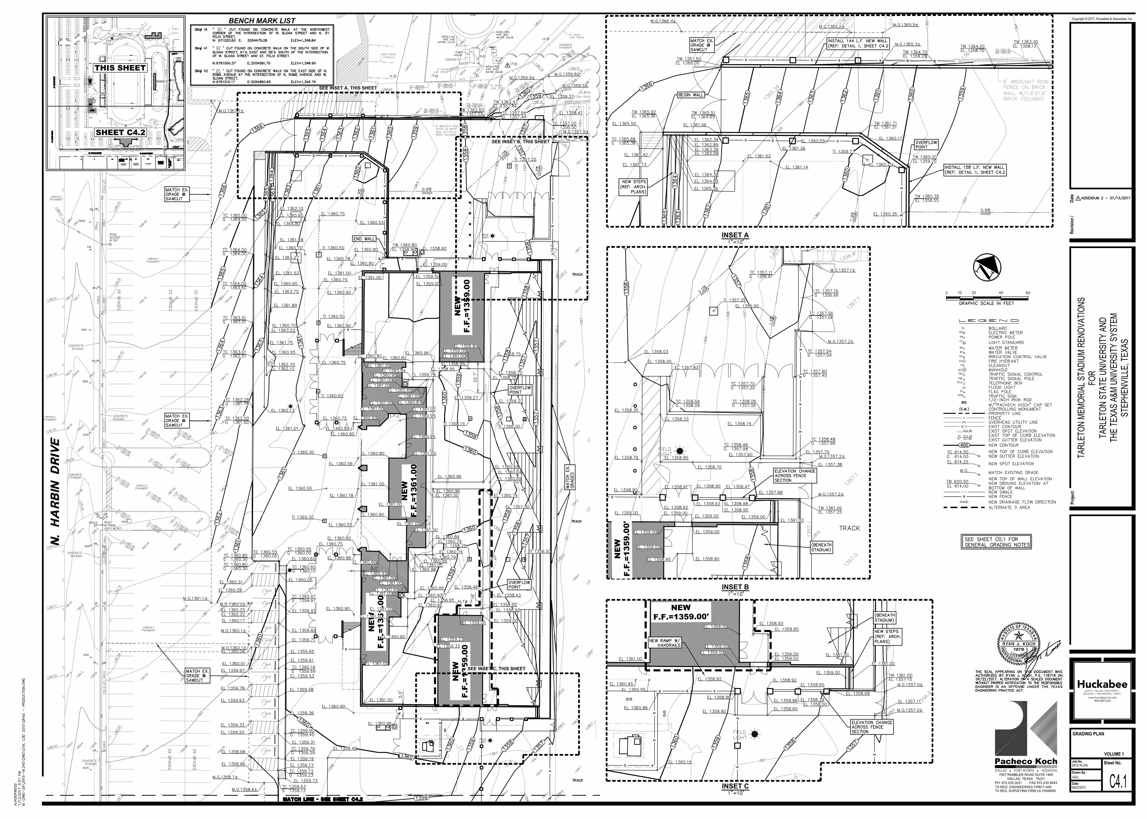
C4.1
GRADING PLAN
2915-16.245
AGU
06/22/2017
SHEET C4.2
THIS SHEET
SEE INSET A, THIS SHEET
BENCH MARK LIST
(
(
(
INSET A
INSET B
NE
W
F.F
.=1
35
9.0
0'
INSET C
NEW
F.F.=1359.00'
SEE INSET B, THIS SHEET
SEE INSET C, THIS SHEET
Sheet No.Job No.
Drawn By:
Date:
Proj
ect:
Copyright © 2017, Huckabee & Associates, Inc.
Revis
ion
/Da
te
VOLUME 1
TARL
ETON
MEM
ORIA
L STA
DIUM
REN
OVAT
IONS
FOR
TARL
ETON
STA
TE U
NIVE
RSITY
AND
THE
TEXA
S A&
M UN
IVER
SITY
SYS
TEM
STEP
HENV
ILLE,
TEXA
S
PH. 972.235.3031 FAX 972.235.9544
DALLAS, TEXAS 75231
7557 RAMBLER ROAD SUITE 1400
Pacheco Koch
TX REG. ENGINEERING FIRM F-469
TX REG. SURVEYING FIRM LS-10008000
DALLAS n FORT WORTH n HOUSTON
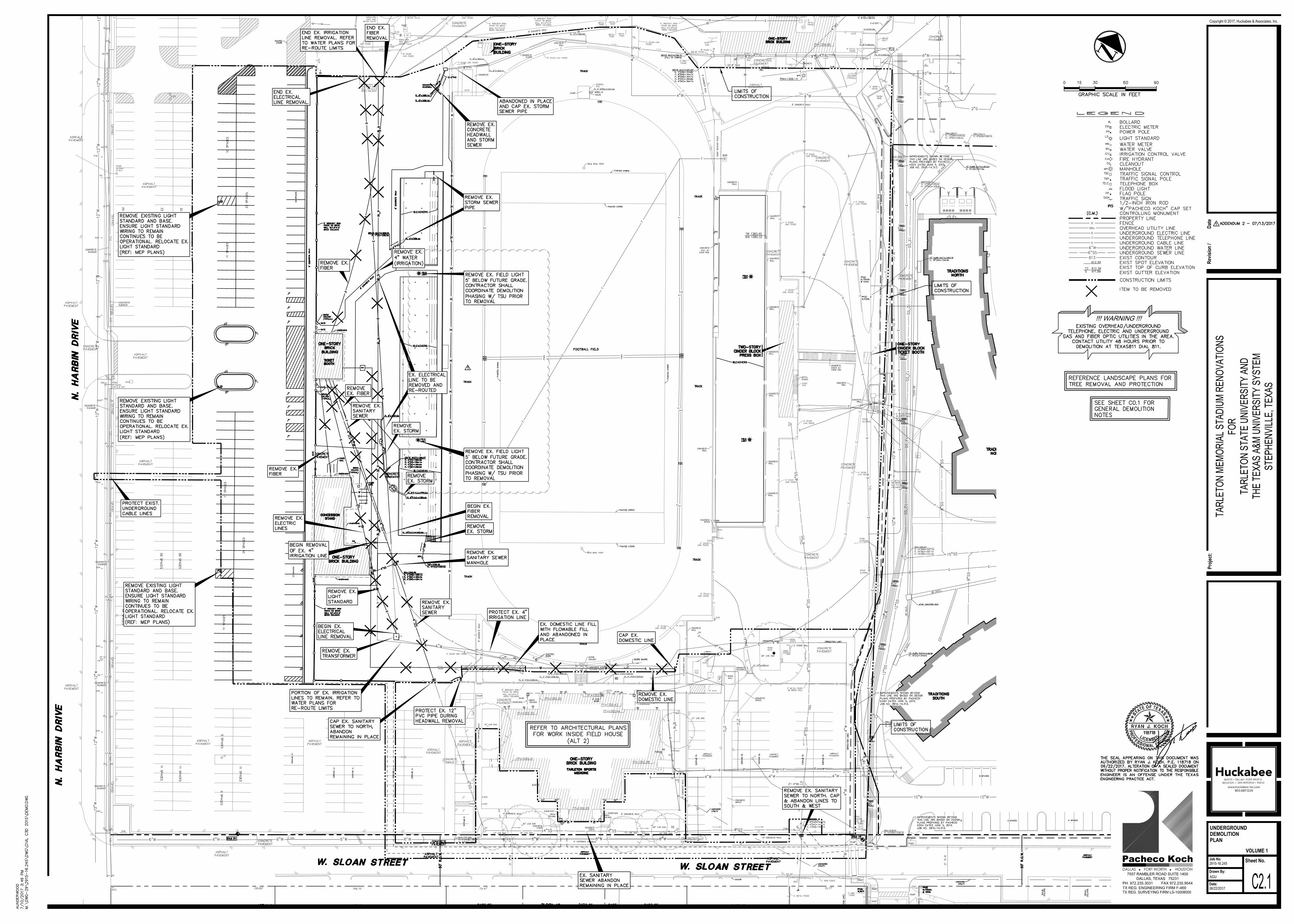
C2.1
UNDERGROUND
DEMOLITION
PLAN
2915-16.245
AGU
06/22/2017
!!! WARNING !!!
Sheet No.Job No.
Drawn By:
Date:
Proj
ect:
Copyright © 2017, Huckabee & Associates, Inc.
Revis
ion
/Da
te
VOLUME 1
TARL
ETON
MEM
ORIA
L STA
DIUM
REN
OVAT
IONS
FOR
TARL
ETON
STA
TE U
NIVE
RSITY
AND
THE
TEXA
S A&
M UN
IVER
SITY
SYS
TEM
STEP
HENV
ILLE,
TEXA
S
PH. 972.235.3031 FAX 972.235.9544
DALLAS, TEXAS 75231
7557 RAMBLER ROAD SUITE 1400
Pacheco Koch
TX REG. ENGINEERING FIRM F-469
TX REG. SURVEYING FIRM LS-10008000
DALLAS n FORT WORTH n HOUSTON
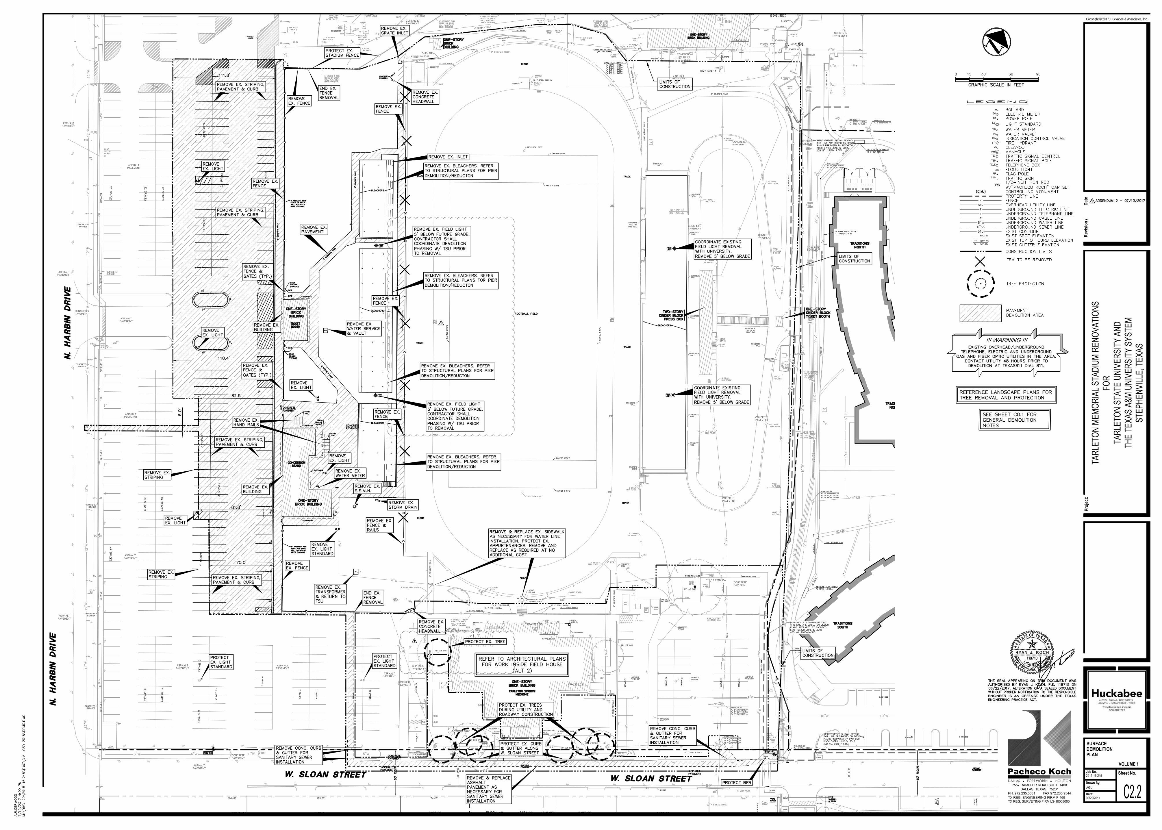
C2.2
SURFACE
DEMOLITION
PLAN
2915-16.245
AGU
06/22/2017
!!! WARNING !!!
NE
W
F.F
.=1
36
1.0
0
NE
W
F.F
.=1
35
9.0
0
NE
W
F.F
.=1
35
9.0
0
NE
W
F.F
.=1
36
1.0
0
Sheet No.Job No.
Drawn By:
Date:
Proj
ect:
Copyright © 2017, Huckabee & Associates, Inc.
Revis
ion
/Da
te
VOLUME 1
TARL
ETON
MEM
ORIA
L STA
DIUM
REN
OVAT
IONS
FOR
TARL
ETON
STA
TE U
NIVE
RSITY
AND
THE
TEXA
S A&
M UN
IVER
SITY
SYS
TEM
STEP
HENV
ILLE,
TEXA
S
PH. 972.235.3031 FAX 972.235.9544
DALLAS, TEXAS 75231
7557 RAMBLER ROAD SUITE 1400
Pacheco Koch
TX REG. ENGINEERING FIRM F-469
TX REG. SURVEYING FIRM LS-10008000
DALLAS n FORT WORTH n HOUSTON
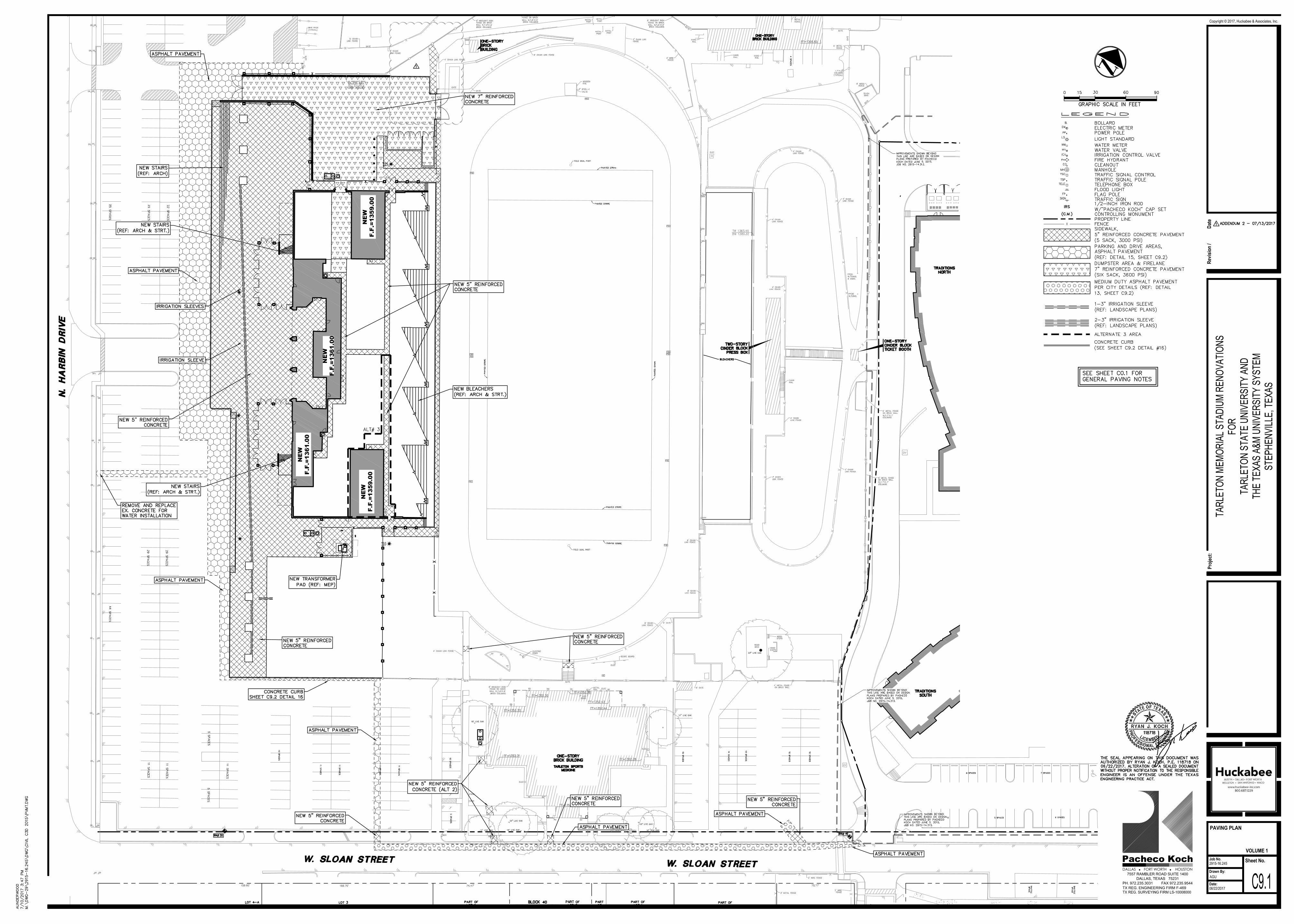
PAVING PLAN
2915-16.245
AGU
06/22/2017
C9.1
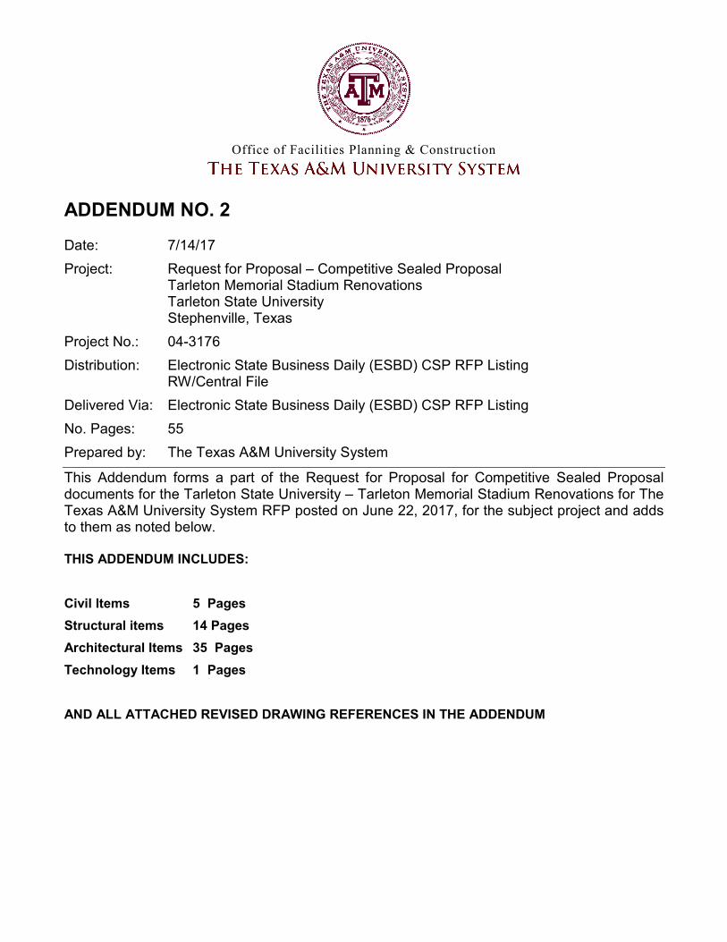
Project Name: Tarleton Memorial Stadium Renovations
Client: Tarleton State University and the Texas A&M University System
Stephenville, Texas
Project Number: 1754-01-01
Structural Items For
Addendum No. 2
Page 1 of 2
STRUCTURAL ITEMS FOR ADDENDUM NO. 2 NOTICE TO PROPOSERS:
A. This Addendum shall be considered part of the contract documents for the above-mentioned project as though it had
been issued at the same time and incorporated integrally therewith. Where provisions of the following supplementary
data differ from those of the original contract documents, this Addendum shall govern and take precedence.
B. Proposers are hereby notified that they shall make any necessary adjustments in their estimate on account of this
Addendum. It will be construed that each Proposer’s proposal is submitted with full knowledge of all modifications and
supplemental data specified therein. Acknowledge receipt of this addendum in the space provided on the proposal form.
Failure to do so may subject Proposer to disqualification.
REFERENCE IS MADE TO THE DRAWINGS AND THE PROJECT MANUAL AS NOTED:
DRAWINGS:
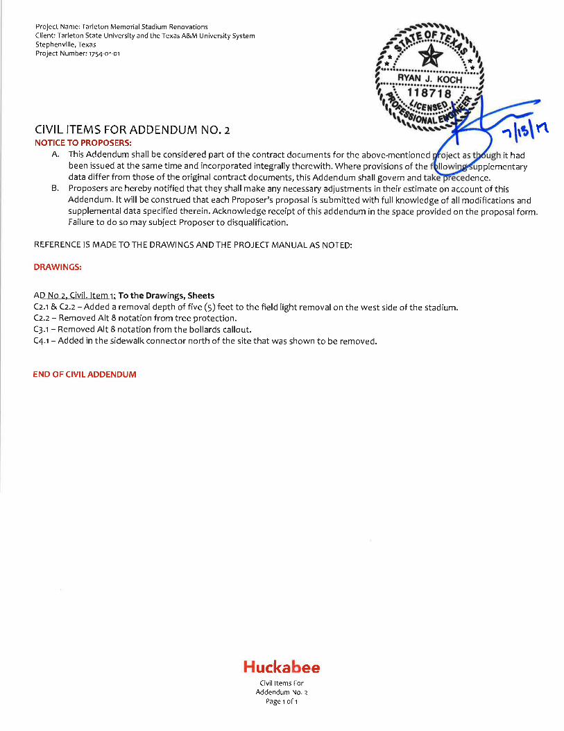
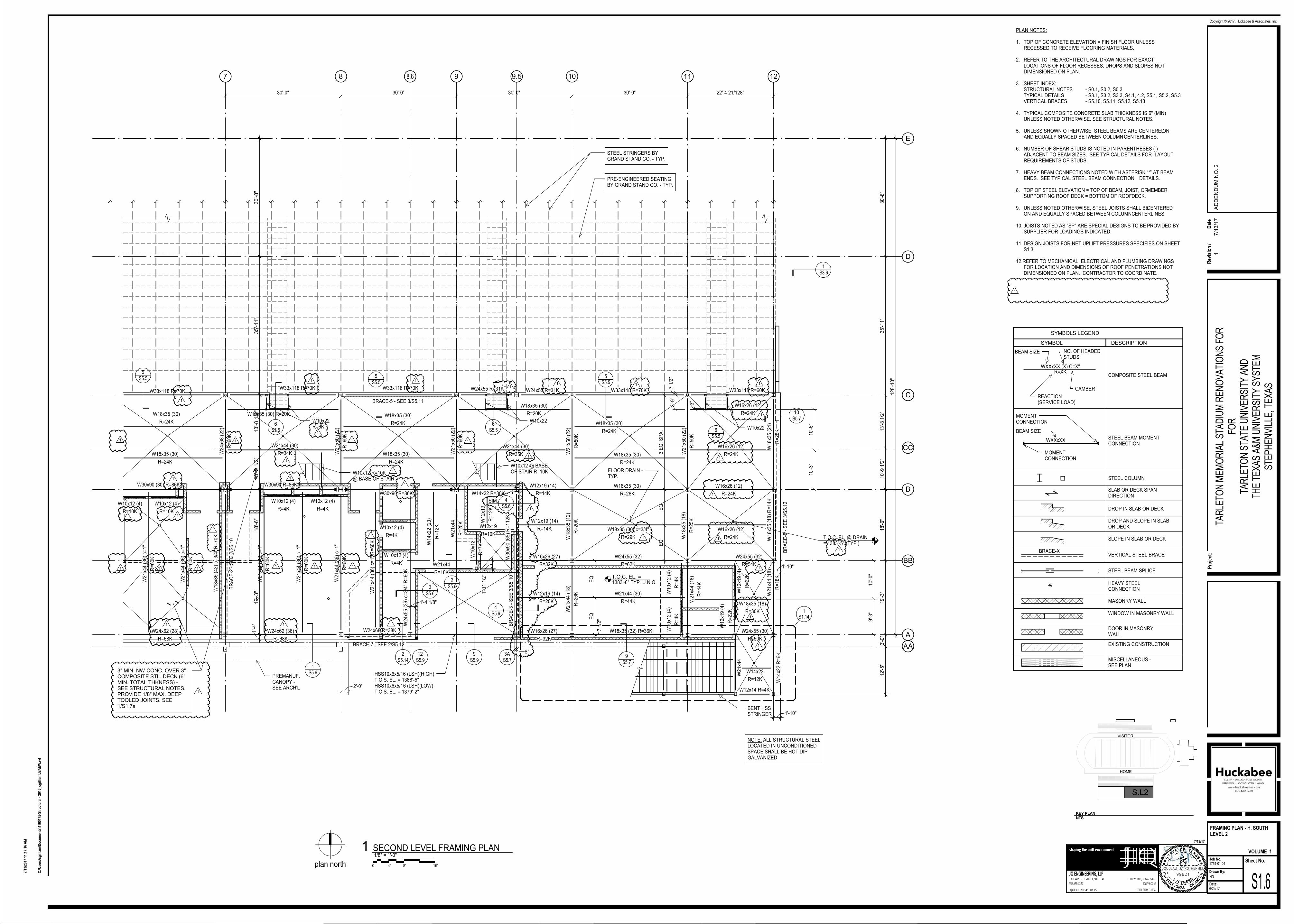
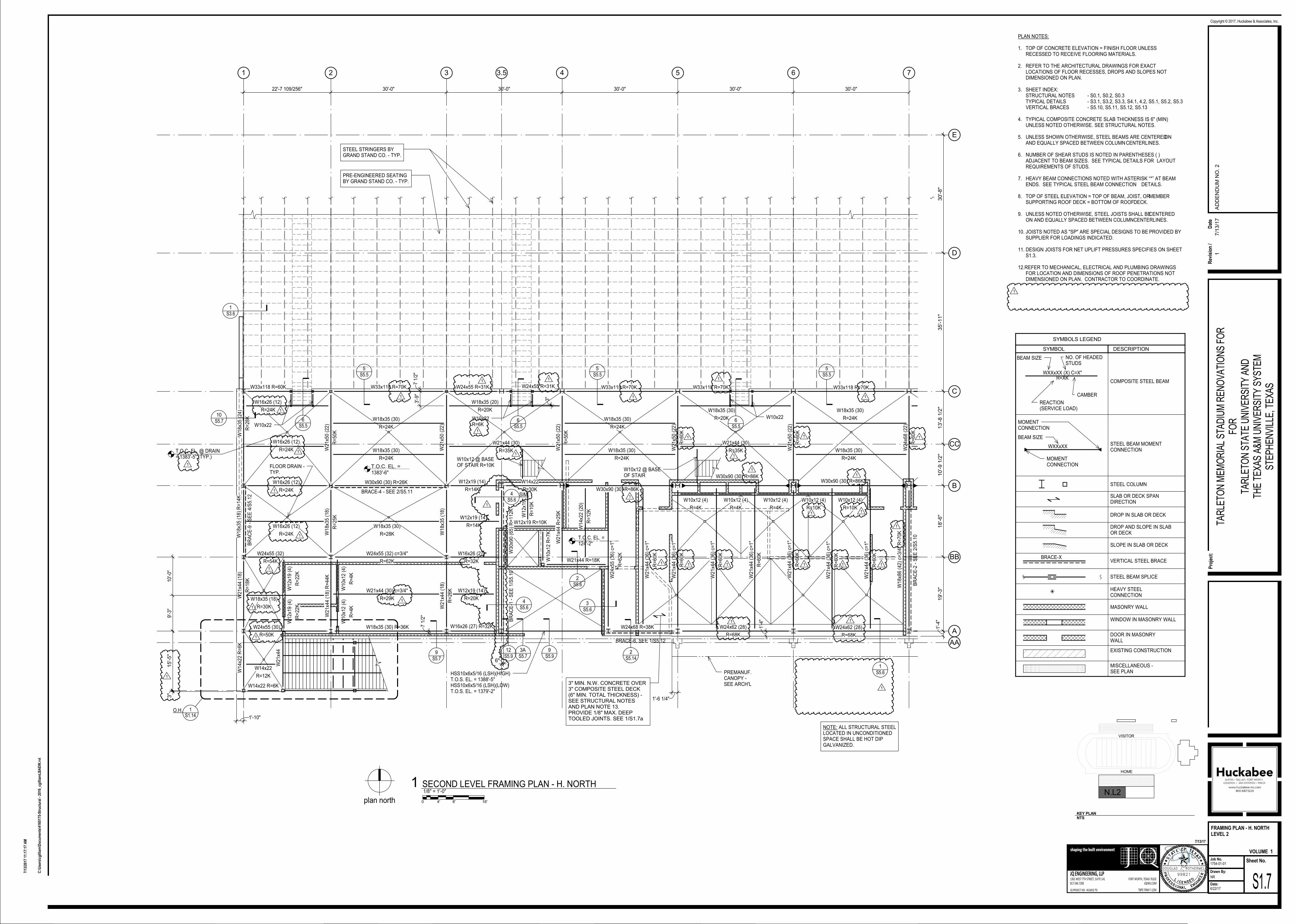
AD No 2 Struct. Item 1: To the Drawings, Sheets S1.6 and S1.7
Revised beam sizes and beam reactions.
AD No 2 Struct. Item 2: To the Drawings, Sheets S1.6 and S1.7
Revised T.O.C. Elevation at floor drains.
AD No 2 Struct. Item 3: To the Drawings, Sheets S1.6 and S1.7
Deleted plan note 13.
AD No 2 Struct. Item 4: To the Drawings, Sheets S1.6 and S1.7
Removed beams and clarified detailing along grids 3.5 and 9.5.
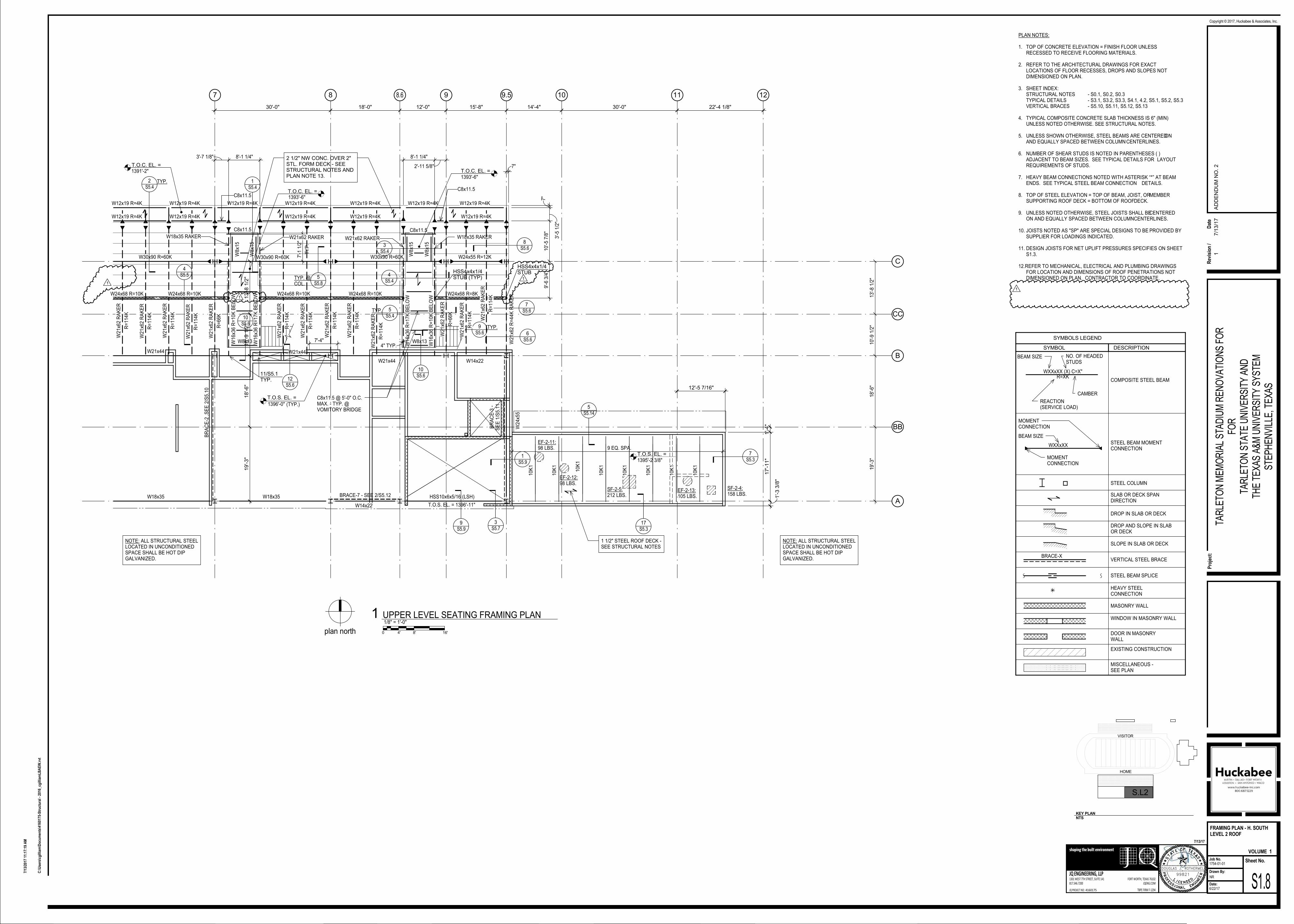
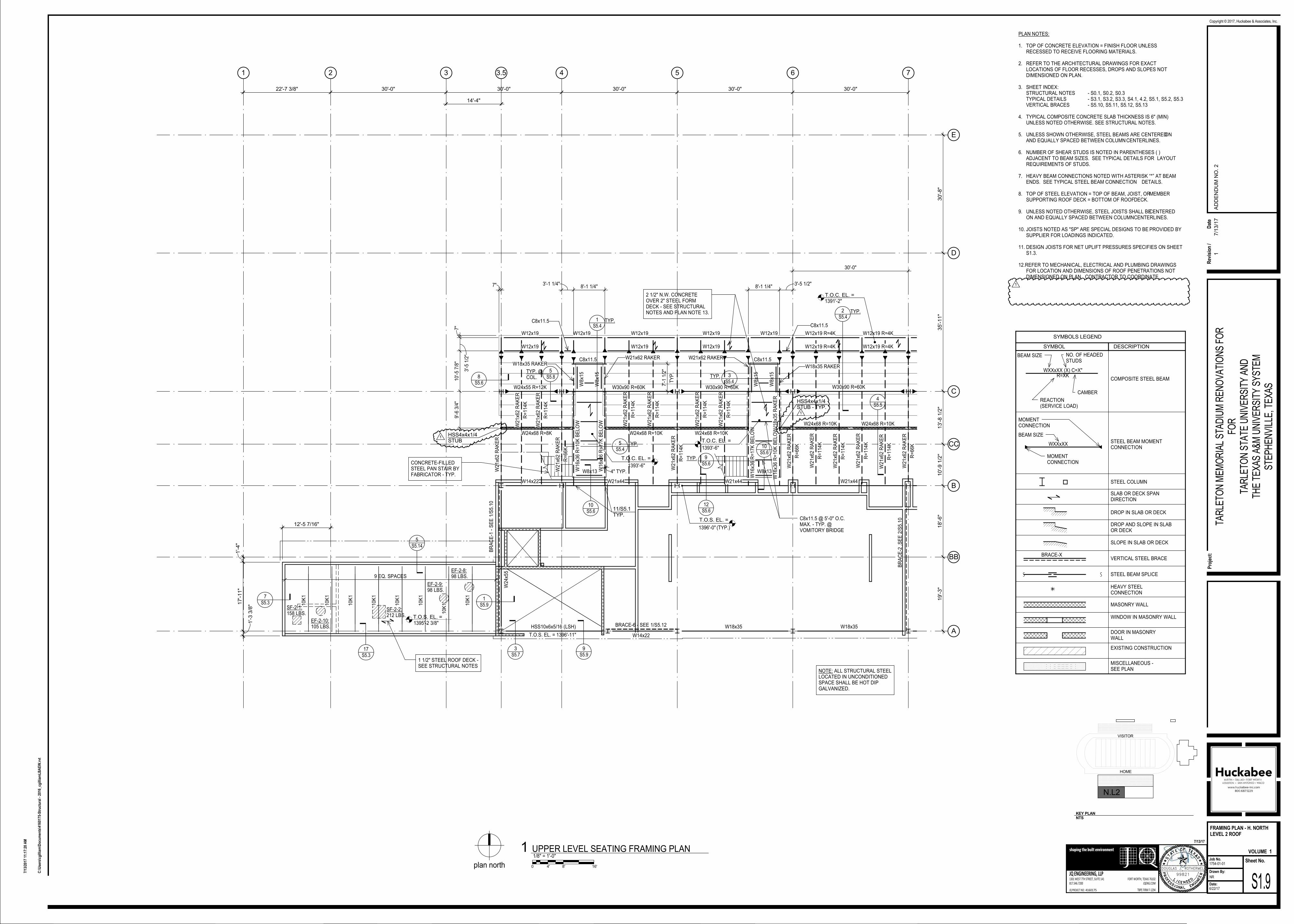
AD No 2 Struct. Item 5: To the Drawings, Sheets S1.8 and S1.9
Added HSS stub column reverences north of grid CC.
AD No 2 Struct. Item 6: To the Drawings, Sheets S1.8 and S1.9
Deleted plan note 13.
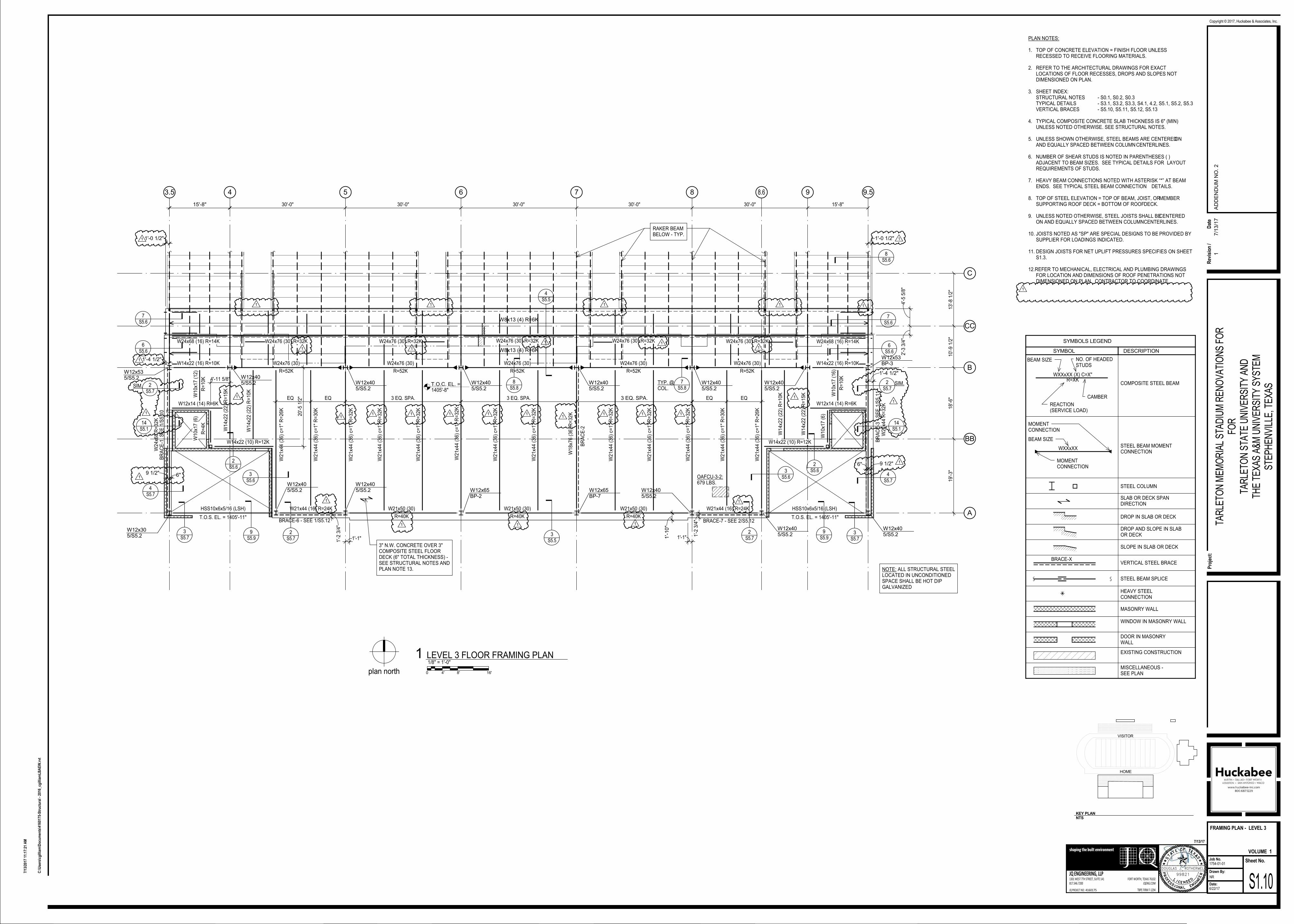
AD No 2 Struct. Item 7: To the Drawings, Sheet S1.10
Deleted plan note 13.
AD No 2 Struct. Item 8: To the Drawings, Sheet S1.10
Revised beam reactions and deleted camber on beam at grid 7.
FIRM NO. 1294
7 8 9 10 11 12
C
A
B
D
E
30'-0" 30'-0" 30'-0" 30'-0" 22'-4 21/128"
12'-5
"3'-0
"19'-3
"18'-6
"10'-9
1/2
"13'-8
1/2
"35'-1
1"
30'-8
"
128
'-10
"
W16x26 (27)
R=32K
NOTE: ALL STRUCTURAL STEELLOCATED IN UNCONDITIONEDSPACE SHALL BE HOT DIPGALVANIZED
W33x118 R=70KW33x118 R=70K W33x118 R=70K
W30x90 (30) R=86K W30x90 R=86K
W30x90 R=86K
W18x35 (30)
R=26K
W16x26 (12)
R=24K
W2
4x6
8 (
22
)
R=
60
K
W2
1x5
0 (
22
)
R=
60
K
W2
1x5
0 (
22
)
R=
60
K
W2
1x5
0 (
22
)
R=
50
K
W2
1x5
0 (
22
)
R=
50
K
W1
8x3
5 (
24
)
R=
28
K
W24x55 (30)
R=50K
W18x35 (32) R=36K
W2
1x4
4
W1
4x2
2 R
=6
K
W24x62 (28)
R=68K
W24x62 (36)
R=68K
W1
8x8
6 (
42
) c=
3/4
" R
=7
0K
W2
1x4
4 (
36
) c=
1"
R=
60
K
W2
4x5
5 (
36
) c=
3/4
" R
=6
0K
PRE-ENGINEERED SEATINGBY GRAND STAND CO. - TYP.
9.5
AA
CC
BB
W16x26 (12)
R=24K
W16x26 (12)
R=24K
10'-3
"10'-6
"
W18x35 (30)
R=20KW18x35 (30) R=20K
W21x44 (30)
R=35K
W1
8x3
5 (
18
)
R=
25
KW
21x4
4 (
18
)
R=
44
K
W1
8x3
5 (
12
)
R=
20
K
W2
1x4
4 (
18
)
R=
26
K
W24x55 (32)
R=62K
W18x35 (30) c=3/4"
R=29K
W18x35 (30)
R=24K
W18x35 (30)
R=24K
3 E
Q.
SP
A.
EQ
EQ
W24x55 (32)
R=54K
W16x26 (12)
R=24K
W18x35 (18)
R=30K
W1
8x3
5 (
18
) R
=14
KW
21x4
4 (
18
)
R=
18
K
W21x44 (30)
R=44K
EQ
EQ
W12x19 (14)
R=20K
W16x26 (27)
R=32K
W18x35 (30)
R=24K
W18x35 (30)
R=24K
W18x35 (30)
R=24K
W18x35 (30)
R=24K
W21x44 (30)
R=34K
W10x22
W10x22
W10x22R=6K
W12x19 (14)
R=14K
W12x19 (14)
R=14K
W2
1x4
4
R=
25
K
W21x44
R=18K
W12x19
R=10K
W1
2x1
9
R=
12
KW14x22 R=30K
W2
1x4
4 (
36
) c=
1"
R=
60
K
W2
1x4
4 (
36
) c=
1"
R=
60
K
W2
1x4
4 (
36
) c=
1"
R=
60
K
W2
1x4
4 (
36
) c=
1"
R=
60
K
W2
1x4
4 (
36
) c=
1"
R=
60
K
W24x68 R=38K
BR
AC
E-2
- S
EE
2/S
5.1
0
BR
AC
E-3
- S
EE
3/S
5.1
0
W10x12 @ BASEOF STAIR R=10KW10x12 R=10K
@ BASE OF STAIR
BRACE-5 - SEE 3/S5.11
BENT HSSSTRINGER
3" MIN. NW CONC. OVER 3"COMPOSITE STL. DECK (6"MIN. TOTAL THKNESS) -SEE STRUCTURAL NOTES.PROVIDE 1/8" MAX. DEEPTOOLED JOINTS. SEE1/S1.7a
STEEL STRINGERS BYGRAND STAND CO. - TYP.
W1
0x1
2
R=
7K
W3
0x9
0 (
65
) R
=11
2K
W33x118 R=60KW24x55 R=31KW24x55 R=31KW33x118 R=70K
5S5.5
6S5.5
3'-9
"7 1
/2"
3"
1'-1
1 1
/2"
1'-4 1/8"
5S5.5
6S5.5
5S5.5
6S5.5
T.O.C. EL. =1383'-6" TYP. U.N.O.
W1
2x1
9 (
4)
R=
22
K
W1
2x1
9 (
4)
R=
22
K
W1
0x1
2 (
4)
R=
4K
W1
0x1
2 (
4)
R=
4K
W10x12 (4)
R=4K
W10x12 (4)
R=4K
W10x12 (4)
R=10K
W10x12 (4)
R=10K
W10x12 (4)
R=4K
W10x12 (4)
R=4K
3S5.6
9S5.9
2S5.6
4S5.6
2S5.14
1S5.6
1S3.6
10S5.7
7 1
/2"
9S5.7
1'-10"
S1.141
W14x22
R=12K
W12x14 R=4K
9'-3
"10'-0
"
BR
AC
E-8
- S
EE
3/S
5.1
2
2'-0"
1'-4
"
PREMANUF.CANOPY -SEE ARCH'L
T.O.C. EL. @ DRAIN= 1383'-5" (TYP.)
FLOOR DRAIN -TYP.
BRACE-7 - SEE 2/S5.12
8.6
W1
4x2
2 (
20
)
R=
12
K
1'-10"
12S5.9
3AS5.7
HSS10x6x5/16 (LSH)(HIGH)T.O.S. EL. = 1388'-5"HSS10x6x5/16 (LSH)(LOW)T.O.S. EL. = 1379'-2"
19'-3"
18'-6"
10'-9 1
/2"
13'-8 1
/2"
35'-11"
30'-8"
1
1
4S5.6
SIM.
6"
1
1
1
1
1
1
1
1 1
11 1
1
1
1
1
1
11
1
1
1
1
1
11
1
1 1 1
1
11
1
111
1 1
1
PLAN NOTES:
1. TOP OF CONCRETE ELEVATION = FINISH FLOOR UNLESSRECESSED TO RECEIVE FLOORING MATERIALS.
2. REFER TO THE ARCHITECTURAL DRAWINGS FOR EXACTLOCATIONS OF FLOOR RECESSES, DROPS AND SLOPES NOTDIMENSIONED ON PLAN.
3. SHEET INDEX:STRUCTURAL NOTES - S0.1, S0.2, S0.3TYPICAL DETAILS - S3.1, S3.2, S3.3, S4.1, 4.2, S5.1, S5.2, S5.3VERTICAL BRACES - S5.10, S5.11, S5.12, S5.13
4. TYPICAL COMPOSITE CONCRETE SLAB THICKNESS IS 6" (MIN)UNLESS NOTED OTHERWISE. SEE STRUCTURAL NOTES.
5. UNLESS SHOWN OTHERWISE, STEEL BEAMS ARE CENTERED ONAND EQUALLY SPACED BETWEEN COLUMN CENTERLINES.
6. NUMBER OF SHEAR STUDS IS NOTED IN PARENTHESES ( )ADJACENT TO BEAM SIZES. SEE TYPICAL DETAILS FOR LAYOUTREQUIREMENTS OF STUDS.
7. HEAVY BEAM CONNECTIONS NOTED WITH ASTERISK “*” AT BEAMENDS. SEE TYPICAL STEEL BEAM CONNECTION DETAILS.
8. TOP OF STEEL ELEVATION = TOP OF BEAM, JOIST, OR MEMBERSUPPORTING ROOF DECK = BOTTOM OF ROOF DECK.
9. UNLESS NOTED OTHERWISE, STEEL JOISTS SHALL BE CENTEREDON AND EQUALLY SPACED BETWEEN COLUMN CENTERLINES.
10. JOISTS NOTED AS "SP" ARE SPECIAL DESIGNS TO BE PROVIDED BYSUPPLIER FOR LOADINGS INDICATED.
11. DESIGN JOISTS FOR NET UPLIFT PRESSURES SPECIFIES ON SHEETS1.3.
12.REFER TO MECHANICAL, ELECTRICAL AND PLUMBING DRAWINGSFOR LOCATION AND DIMENSIONS OF ROOF PENETRATIONS NOTDIMENSIONED ON PLAN. CONTRACTOR TO COORDINATE.
WXXxXX (X) C=X"
BEAM SIZE
REACTION(SERVICE LOAD)
NO. OF HEADEDSTUDS
R=XK
CAMBER
SYMBOLS LEGEND
SYMBOL DESCRIPTION
COMPOSITE STEEL BEAM
MOMENTCONNECTION
MOMENTCONNECTION
WXXxXXSTEEL BEAM MOMENTCONNECTION
SLAB OR DECK SPANDIRECTION
DROP IN SLAB OR DECK
DROP AND SLOPE IN SLABOR DECK
SLOPE IN SLAB OR DECK
HEAVY STEELCONNECTION
EXISTING CONSTRUCTION
MASONRY WALL
STEEL COLUMN
STEEL BEAM SPLICE
MISCELLANEOUS -SEE PLAN
WINDOW IN MASONRY WALL
DOOR IN MASONRYWALL
BRACE-XVERTICAL STEEL BRACE
BEAM SIZE
DOUGLAS J. ROTHERMEL
99821
1301 WEST 7TH STREET, SUITE 141
817.546.7200
FORT WORTH, TEXAS 76102
TBPE FIRM F-1294
JQ ENGINEERING, LLP
JQENG.COM
JQ PROJECT NO:
shaping the built environment
Sheet No.Job No.
Drawn By:
Date:
Pro
ject
:
Copyright © 2017, Huckabee & Associates, Inc.
VOLUME
4160175
7/13/17
C:\
Use
rs\c
gill
iam
\Do
cum
ents
\416
0175
-Str
uct
ura
l - 2
016_
cgill
iam
LB
AE
W.r
vt
7/13
/201
7 11
:17:
16 A
M
NR
S1.6
FRAMING PLAN - H. SOUTH
LEVEL 2
6/22/17
1754-01-01
TAR
LETO
N M
EM
OR
IAL
STA
DIU
M R
EN
OV
ATI
ON
S F
OR
FOR
TAR
LETO
N S
TATE
UN
IVE
RS
ITY
AN
DTH
E T
EX
AS
A&
M U
NIV
ER
SIT
Y S
YS
TEM
STE
PH
EN
VIL
LE, T
EX
AS
1
HOME
KEY PLAN
NTS
S.L2
VISITOR
0 4' 8' 16'plan north
1/8" = 1'-0"SECOND LEVEL FRAMING PLAN1
1
Rev
isio
n /
Dat
e
17/1
3/1
7A
DD
EN
DU
M N
O. 2
1 2 3 4 5 6 7
C
A
B
D
E
22'-7 109/256" 30'-0" 30'-0" 30'-0" 30'-0" 30'-0"
W16x26 (27)
R=32K
3" MIN. N.W. CONCRETE OVER3" COMPOSITE STEEL DECK(6" MIN. TOTAL THICKNESS) -SEE STRUCTURAL NOTESAND PLAN NOTE 13.PROVIDE 1/8" MAX. DEEPTOOLED JOINTS. SEE 1/S1.7a
W33x118 R=70K W33x118 R=70K
W1
8x3
5 (
24
)
R=
28
K
W2
1x5
0 (
22
)
R=
50
K
W2
1x5
0 (
22
)
W2
1x5
0 (
22
)
R=
50
K
W30x90 (30) R=26KW16x26 (12)
R=24K
W24x55 (30)
R=50K
W18x35 (30) R=36K
W14x22
R=12K
W2
1x4
4
W30x90 (30) R=86K
W30x90 (30) R=86KW30x90 (30) R=86K
W2
1x5
0 (
22
)
R=
60
K
W2
1x5
0 (
22
)
R=
60
K
W2
4x6
8 (
22
)
R=
60
K
W24x62 (28)
R=68K
W24x62 (28)
R=68K
W14x22 R=6K
W2
4x5
5 (
36
) c=
1"
R=
62
K
W2
1x4
4 (
36
) c=
1"
R=
60
K
W2
1x4
4 (
36
) c=
1"
R=
60
K
W1
8x8
6 (
42
) c=
3/4
" R
=7
0K
T.O.C. EL. =124'-2"
3.5
AA
CC
BB
W18x35 (30)
R=20K
W18x35 (20)
R=20K
W16x26 (12)
R=24K
W21x44 (30)
R=35K
W16x26 (12)
R=24K W18x35 (30)
R=24K
W18x35 (30)
R=24K
W18x35 (30)
R=24K
W18x35 (30)
R=24K
W18x35 (30)
R=24K
W18x35 (30)
R=24K
W21x44 (30)
R=35K
W10x22
W24x55 (32)
R=54K
W16x26 (12)
R=24K
W18x35 (18)
R=30K
W1
8x3
5 (
18
) R
=14
KW
21x4
4 (
18
)
R=
18
K
W1
4x2
2 R
=6
K
W12x19 (14)
R=14K
W14x22
R=30K
W10x22R=6KW10x22
W2
1x4
4 R
=2
5K
W12x19 R=10K
W21x44 R=18K
W1
2x1
9
R=
10
K
W12x19 (14)
R=20K
W16x26 (27) R=32K
W12x19 (14)
R=14K
W24x55 (32) c=3/4"
R=62K
W18x35 (30)
R=28K
W21x44 (30) c=3/4"
R=29K
W2
1x4
4 (
36
) c=
1"
R=
60
K
W2
1x4
4 (
36
) c=
1"
R=
60
K
W2
1x4
4 (
36
) c=
1"
R=
60
K
W2
1x4
4 (
36
) c=
1"
R=
60
K
W24x68 R=38K
BR
AC
E-2
- S
EE
2/S
5.1
0W1
8x3
5 (
18
)
R=
25
K
W2
1x4
4 (
18
) R
=44
K
W2
1x4
4 (
18
)
R=
26
K
W1
8x3
5 (
18
)
W10x12 @ BASEOF STAIR R=10K
W10x12 @ BASEOF STAIR
W2
1x4
4 (
36
) c=
1"
R=
60
K
PRE-ENGINEERED SEATINGBY GRAND STAND CO. - TYP.
STEEL STRINGERS BYGRAND STAND CO. - TYP.
W3
0x9
0 (
65
) R
=11
2K
W1
0x1
2 R
=7
K
3'-9
"7 1
/2"
W33x118 R=70K
3"
W24x55 R=31KW24x55 R=31KW33x118 R=70KW33x118 R=60K
5S5.5
5S5.5
5S5.5
6S5.5
6S5.5
6S5.5
T.O.C. EL. =1383'-6"
W10x12 (4)
R=4K
W10x12 (4)
R=4K
W10x12 (4)
R=4K
W10x12 (4)
R=10K
W10x12 (4)
R=10K
W1
2x1
9 (
4)
R=
22
K
W1
2x1
9 (
4)
R=
22
K
W1
0x1
2 (
4)
R=
4K
W1
0x1
2 (
4)
R=
4K
1S3.6
10S5.7
4S5.6
3S5.6
1'-4
"
7 1
/2"
S1.141O.H.
1'-10"
2S5.6
9S5.9
9S5.7
1S5.6
BR
AC
E-9
- S
EE
4/S
5.1
2
1'-4
"
PREMANUF.CANOPY -SEE ARCH'L
1'-6 1/4"
BRACE-4 - SEE 2/S5.11
T.O.C. EL. @ DRAIN= 1383'-5" (TYP.)
9'-3
"10'-0
"
FLOOR DRAIN -TYP.
BRACE-6, SEE 1/S5.12
BR
AC
E-1
- S
EE
1/S
5.1
0
W1
4x2
2 (
20
)
R=
12
K
12S5.9
2S5.14
3AS5.7
NOTE: ALL STRUCTURAL STEELLOCATED IN UNCONDITIONEDSPACE SHALL BE HOT DIPGALVANIZED.
HSS10x6x5/16 (LSH)(HIGH)T.O.S. EL. = 1388'-5"HSS10x6x5/16 (LSH)(LOW)T.O.S. EL. = 1379'-2"
19'-3"
18'-6"
10'-9 1
/2"
13'-8 1
/2"
35'-11"
30'-8"
4S5.6
SIM.
6"
1
1
1
1
1
1
1
1
1
1
1
1
3"
15'-5"
1
1
1
1
1
1
111111
1 1
1
1
1
1
1
1
1
1
11
11
PLAN NOTES:
1. TOP OF CONCRETE ELEVATION = FINISH FLOOR UNLESSRECESSED TO RECEIVE FLOORING MATERIALS.
2. REFER TO THE ARCHITECTURAL DRAWINGS FOR EXACTLOCATIONS OF FLOOR RECESSES, DROPS AND SLOPES NOTDIMENSIONED ON PLAN.
3. SHEET INDEX:STRUCTURAL NOTES - S0.1, S0.2, S0.3TYPICAL DETAILS - S3.1, S3.2, S3.3, S4.1, 4.2, S5.1, S5.2, S5.3VERTICAL BRACES - S5.10, S5.11, S5.12, S5.13
4. TYPICAL COMPOSITE CONCRETE SLAB THICKNESS IS 6" (MIN)UNLESS NOTED OTHERWISE. SEE STRUCTURAL NOTES.
5. UNLESS SHOWN OTHERWISE, STEEL BEAMS ARE CENTERED ONAND EQUALLY SPACED BETWEEN COLUMN CENTERLINES.
6. NUMBER OF SHEAR STUDS IS NOTED IN PARENTHESES ( )ADJACENT TO BEAM SIZES. SEE TYPICAL DETAILS FOR LAYOUTREQUIREMENTS OF STUDS.
7. HEAVY BEAM CONNECTIONS NOTED WITH ASTERISK “*” AT BEAMENDS. SEE TYPICAL STEEL BEAM CONNECTION DETAILS.
8. TOP OF STEEL ELEVATION = TOP OF BEAM, JOIST, OR MEMBERSUPPORTING ROOF DECK = BOTTOM OF ROOF DECK.
9. UNLESS NOTED OTHERWISE, STEEL JOISTS SHALL BE CENTEREDON AND EQUALLY SPACED BETWEEN COLUMN CENTERLINES.
10. JOISTS NOTED AS "SP" ARE SPECIAL DESIGNS TO BE PROVIDED BYSUPPLIER FOR LOADINGS INDICATED.
11. DESIGN JOISTS FOR NET UPLIFT PRESSURES SPECIFIES ON SHEETS1.3.
12.REFER TO MECHANICAL, ELECTRICAL AND PLUMBING DRAWINGSFOR LOCATION AND DIMENSIONS OF ROOF PENETRATIONS NOTDIMENSIONED ON PLAN. CONTRACTOR TO COORDINATE.
WXXxXX (X) C=X"
BEAM SIZE
REACTION(SERVICE LOAD)
NO. OF HEADEDSTUDS
R=XK
CAMBER
SYMBOLS LEGEND
SYMBOL DESCRIPTION
COMPOSITE STEEL BEAM
MOMENTCONNECTION
MOMENTCONNECTION
WXXxXXSTEEL BEAM MOMENTCONNECTION
SLAB OR DECK SPANDIRECTION
DROP IN SLAB OR DECK
DROP AND SLOPE IN SLABOR DECK
SLOPE IN SLAB OR DECK
HEAVY STEELCONNECTION
EXISTING CONSTRUCTION
MASONRY WALL
STEEL COLUMN
STEEL BEAM SPLICE
MISCELLANEOUS -SEE PLAN
WINDOW IN MASONRY WALL
DOOR IN MASONRYWALL
BRACE-XVERTICAL STEEL BRACE
BEAM SIZE
DOUGLAS J. ROTHERMEL
99821
1301 WEST 7TH STREET, SUITE 141
817.546.7200
FORT WORTH, TEXAS 76102
TBPE FIRM F-1294
JQ ENGINEERING, LLP
JQENG.COM
JQ PROJECT NO:
shaping the built environment
Sheet No.Job No.
Drawn By:
Date:
Pro
ject
:
Copyright © 2017, Huckabee & Associates, Inc.
VOLUME
4160175
7/13/17
C:\
Use
rs\c
gill
iam
\Do
cum
ents
\416
0175
-Str
uct
ura
l - 2
016_
cgill
iam
LB
AE
W.r
vt
7/13
/201
7 11
:17:
17 A
M
NR
S1.7
FRAMING PLAN - H. NORTH
LEVEL 2
6/22/17
1754-01-01
TAR
LETO
N M
EM
OR
IAL
STA
DIU
M R
EN
OV
ATI
ON
S F
OR
FOR
TAR
LETO
N S
TATE
UN
IVE
RS
ITY
AN
DTH
E T
EX
AS
A&
M U
NIV
ER
SIT
Y S
YS
TEM
STE
PH
EN
VIL
LE, T
EX
AS
1
HOME
KEY PLAN
NTS
N.L2
VISITOR
0 4' 8' 16'plan north
1/8" = 1'-0"SECOND LEVEL FRAMING PLAN - H. NORTH1
1
Rev
isio
n /
Dat
e
17/1
3/1
7A
DD
EN
DU
M N
O. 2
7 8 9 10 11 12
C
A
B
9.5
CC
BB
W2
1x6
2 R
AK
ER
R=
11
4K
W2
1x6
2 R
AK
ER
R=
66
K
W2
1x6
2 R
AK
ER
R=
11
4K
W30x90 R=60K W30x90 R=60K W30x90 R=60K W24x55 R=12K
W12x19 R=4K W12x19 R=4K
W12x19 R=4K
W12x19 R=4K W12x19 R=4K
W12x19 R=4K
W12x19 R=4K
W12x19 R=4K
W12x19 R=4K W12x19 R=4K
W8
x15
W8
x15
C8x11.5 C8x11.5
W8
x15
W8
x15
W1
6x3
6 R
=1
7K
BE
LO
W
W1
6x3
6 R
=1
0K
BE
LO
WW21x62 RAKER
C8x11.5
W18x35 RAKER
W2
1x6
2 R
AK
ER
R=
66
K
W2
1x6
2 R
=4
4K
RA
KE
R
W1
6x3
6 R
=1
0K
BE
LO
W
W1
6x3
6 R
=1
7K
BE
LO
W
C8x11.5
HSS4x4x1/4STUB (TYP)
1 1/2" STEEL ROOF DECK -SEE STRUCTURAL NOTES
W21x44
W21x44
W14x22
W18x35 W18x35
W14x22
19'-3
"18'-6
"10'-9
1/2
"13'-8
1/2
"
BR
AC
E-2
,S
EE
2/S
5.1
0
BR
AC
E-3
-S
EE
1/S
5.1
1
2 1/2" NW CONC. OVER 2"STL. FORM DECK - SEESTRUCTURAL NOTES ANDPLAN NOTE 13.
W21x44
4S5.5
2S5.4
TYP. 1S5.4
3
S5.4
5S5.4
TYP.
5S5.14
7S5.3
17S5.3
HSS10x6x5/16 (LSH)
3S5.7
1'-3 3
/8"
17'-11"
1'-4"
12'-5 7/16"
1S5.9
11/S5.1TYP.
W24x68 R=10K W24x68 R=10K W24x68 R=8K
8'-1 1/4"
2'-11 5/8"
4" TYP.
7"
3'-5
1/2
"
10'-5
7/8
"9'-6
3/4
"
3'-7 1/8" 8'-1 1/4"
T.O.C. EL. =1391'-2"
7"
TY
P.
7'-1
1/2
"
W8x13W8x13
T.O.C. EL. =1393'-6"
T.O.C. EL. =1393'-6"
T.O.S. EL. =
1396'-0" (TYP.)
8S5.6
9S5.6
TYP.
10S5.6
10S5.6
7S5.6
6S5.6
W24x68 R=10KW24x68 R=10K
W12x19 R=4K
W21x62 RAKERW18x35 RAKER
7'-4"
C8x11.5 @ 5'-0" O.C.MAX. - TYP. @VOMITORY BRIDGE
5S5.8
TYP. @COL.
12S5.6
10
K1
10
K1
10
K1
10
K1
10
K1
10
K1
10
K1
10
K1
9 EQ. SPA.
BRACE-7 - SEE 2/S5.12
EF-2-11:98 LBS.
EF-2-12:98 LBS.
SF-2-5:212 LBS.
EF-2-13:105 LBS.
SF-2-4:158 LBS.
T.O.S. EL. =1395'-2 3/8"
4S5.4
8.6
W2
1x6
2 R
AK
ER
R=
11
4K
W2
1x6
2 R
AK
ER
R=
11
4K
W2
1x6
2 R
AK
ER
R=
11
4K
9S5.9
W2
1x6
2 R
AK
ER
R=
11
4K
W2
1x6
2 R
AK
ER
R=
11
4K
W2
1x6
2 R
AK
ER
R=
11
4K
W2
1x6
2 R
AK
ER
R=
11
4K
W2
1x6
2 R
AK
ER
R=
11
4K
W2
1x6
2 R
AK
ER
R=
11
4K
W12x19 R=4K
W2
4x5
5
NOTE: ALL STRUCTURAL STEELLOCATED IN UNCONDITIONEDSPACE SHALL BE HOT DIPGALVANIZED.
NOTE: ALL STRUCTURAL STEELLOCATED IN UNCONDITIONEDSPACE SHALL BE HOT DIPGALVANIZED.
T.O.S. EL. = 1396'-11"
30'-0" 18'-0" 12'-0" 15'-8" 14'-4" 30'-0" 22'-4 1/8"
19'-3"
18'-6"
10'-9 1
/2"
13'-8 1
/2"
1
HSS4x4x1/4STUB
11
PLAN NOTES:
1. TOP OF CONCRETE ELEVATION = FINISH FLOOR UNLESSRECESSED TO RECEIVE FLOORING MATERIALS.
2. REFER TO THE ARCHITECTURAL DRAWINGS FOR EXACTLOCATIONS OF FLOOR RECESSES, DROPS AND SLOPES NOTDIMENSIONED ON PLAN.
3. SHEET INDEX:STRUCTURAL NOTES - S0.1, S0.2, S0.3TYPICAL DETAILS - S3.1, S3.2, S3.3, S4.1, 4.2, S5.1, S5.2, S5.3VERTICAL BRACES - S5.10, S5.11, S5.12, S5.13
4. TYPICAL COMPOSITE CONCRETE SLAB THICKNESS IS 6" (MIN)UNLESS NOTED OTHERWISE. SEE STRUCTURAL NOTES.
5. UNLESS SHOWN OTHERWISE, STEEL BEAMS ARE CENTERED ONAND EQUALLY SPACED BETWEEN COLUMN CENTERLINES.
6. NUMBER OF SHEAR STUDS IS NOTED IN PARENTHESES ( )ADJACENT TO BEAM SIZES. SEE TYPICAL DETAILS FOR LAYOUTREQUIREMENTS OF STUDS.
7. HEAVY BEAM CONNECTIONS NOTED WITH ASTERISK “*” AT BEAMENDS. SEE TYPICAL STEEL BEAM CONNECTION DETAILS.
8. TOP OF STEEL ELEVATION = TOP OF BEAM, JOIST, OR MEMBERSUPPORTING ROOF DECK = BOTTOM OF ROOF DECK.
9. UNLESS NOTED OTHERWISE, STEEL JOISTS SHALL BE CENTEREDON AND EQUALLY SPACED BETWEEN COLUMN CENTERLINES.
10. JOISTS NOTED AS "SP" ARE SPECIAL DESIGNS TO BE PROVIDED BYSUPPLIER FOR LOADINGS INDICATED.
11. DESIGN JOISTS FOR NET UPLIFT PRESSURES SPECIFIES ON SHEETS1.3.
12.REFER TO MECHANICAL, ELECTRICAL AND PLUMBING DRAWINGSFOR LOCATION AND DIMENSIONS OF ROOF PENETRATIONS NOTDIMENSIONED ON PLAN. CONTRACTOR TO COORDINATE.
WXXxXX (X) C=X"
BEAM SIZE
REACTION(SERVICE LOAD)
NO. OF HEADEDSTUDS
R=XK
CAMBER
SYMBOLS LEGEND
SYMBOL DESCRIPTION
COMPOSITE STEEL BEAM
MOMENTCONNECTION
MOMENTCONNECTION
WXXxXXSTEEL BEAM MOMENTCONNECTION
SLAB OR DECK SPANDIRECTION
DROP IN SLAB OR DECK
DROP AND SLOPE IN SLABOR DECK
SLOPE IN SLAB OR DECK
HEAVY STEELCONNECTION
EXISTING CONSTRUCTION
MASONRY WALL
STEEL COLUMN
STEEL BEAM SPLICE
MISCELLANEOUS -SEE PLAN
WINDOW IN MASONRY WALL
DOOR IN MASONRYWALL
BRACE-XVERTICAL STEEL BRACE
BEAM SIZE
DOUGLAS J. ROTHERMEL
99821
1301 WEST 7TH STREET, SUITE 141
817.546.7200
FORT WORTH, TEXAS 76102
TBPE FIRM F-1294
JQ ENGINEERING, LLP
JQENG.COM
JQ PROJECT NO:
shaping the built environment
Sheet No.Job No.
Drawn By:
Date:
Pro
ject
:
Copyright © 2017, Huckabee & Associates, Inc.
VOLUME
4160175
7/13/17
C:\
Use
rs\c
gill
iam
\Do
cum
ents
\416
0175
-Str
uct
ura
l - 2
016_
cgill
iam
LB
AE
W.r
vt
7/13
/201
7 11
:17:
19 A
M
NR
S1.8
FRAMING PLAN - H. SOUTH
LEVEL 2 ROOF
6/22/17
1754-01-01
TAR
LETO
N M
EM
OR
IAL
STA
DIU
M R
EN
OV
ATI
ON
S F
OR
FOR
TAR
LETO
N S
TATE
UN
IVE
RS
ITY
AN
DTH
E T
EX
AS
A&
M U
NIV
ER
SIT
Y S
YS
TEM
STE
PH
EN
VIL
LE, T
EX
AS
1
0 4' 8' 16'plan north
1/8" = 1'-0"UPPER LEVEL SEATING FRAMING PLAN1
HOME
KEY PLAN
NTS
S.L2
VISITOR
1
Rev
isio
n /
Dat
e
17/1
3/1
7A
DD
EN
DU
M N
O. 2
1 2 3 4 5 6 7
C
A
B
D
E
3.5
CC
BB
W12x19
W12x19
W12x19 W12x19 W12x19
W2
1x6
2 R
AK
ER
R=
66
K
W2
1x6
2 R
AK
ER
W2
1x6
2 R
AK
ER
R=
11
4K
W2
1x6
2 R
AK
ER
R=
66
K
W2
1x6
2 R
AK
ER
R=
11
4K
W2
1x6
2 R
AK
ER
R=
66
K
C8x11.5
W12x19 W12x19
W30x90 R=60KW24x55 R=12K W30x90 R=60K
W1
6x3
6 R
=1
7K
BE
LO
W
W30x90 R=60K
W12x19 R=4K
C8x11.5
W12x19 R=4K
W12x19 R=4K
W8
x15
W8
x15
C8x11.5 C8x11.5
W8
x15
W8
x15
W1
6x3
6 R
=1
7K
BE
LO
W
W12x19
C8x11.5
9 EQ. SPACES
1 1/2" STEEL ROOF DECK -SEE STRUCTURAL NOTES
HSS10x6x5/16 (LSH)
W14x22
W18x35 W18x35
CONCRETE-FILLEDSTEEL PAN STAIR BYFABRICATOR - TYP.
2 1/2" N.W. CONCRETEOVER 2" STEEL FORMDECK - SEE STRUCTURALNOTES AND PLAN NOTE 13.
22'-7 3/8" 30'-0" 30'-0" 30'-0" 30'-0" 30'-0"
BR
AC
E-1
- S
EE
1/S
5.1
0
BR
AC
E-2
,S
EE
2/S
5.1
0
W14x22 W21x44 W21x44 W21x44
4S5.5
1S5.4
2S5.4
3S5.4
5S5.4
TYP.
TYP.
12'-5 7/16"
1'-3 3
/8"1
7'-11"
1'-4"
TYP.
TYP.
3S5.7
5S5.14
7S5.3
17S5.3
1S5.9
11/S5.1TYP.
W2
4x5
5
W1
8x3
5 R
AK
ER
W1
6x3
6 R
=1
0K
BE
LO
W
W1
6x3
6 R
=1
0K
BE
LO
WW24x68 R=8K W24x68 R=10K W24x68 R=10K
T.O.C. EL. =1391'-2"
W8x13W8x13
T.O.C. EL. =
1393'-6"
T.O.C. EL. =
1393'-6"
3'-1 1/4"8'-1 1/4" 8'-1 1/4"
3'-5 1/2"7"
9'-6
3/4
"10'-5
7/8
"
3'-5
1/2
"
7"
10S5.6
10S5.6
9S5.6
TYP.
T.O.S. EL. =
1396'-0" (TYP.)
TY
P.
7'-1
1/2
"
8S5.6
4" TYP.
W24x68 R=10KW24x68 R=10K
W12x19 R=4K
W21x62 RAKER W21x62 RAKER
W18x35 RAKERW18x35 RAKER
5S5.8
TYP. @COL.
C8x11.5 @ 5'-0" O.C.MAX. - TYP. @VOMITORY BRIDGE
12S5.6
T.O.S. EL. =1395'-2 3/8"
10
K1
10
K1
10
K1
10
K1
10
K1
10
K1
10
K1 10
K1
BRACE-6 - SEE 1/S5.12EF-2-10:105 LBS.
SF-2-1:158 LBS.
SF-2-2:212 LBS.
EF-2-9:98 LBS.
EF-2-8:98 LBS.
30'-0"
W2
1x6
2 R
AK
ER
R=
11
4K
W2
1x6
2 R
AK
ER
R=
11
4K
W2
1x6
2 R
AK
ER
R=
11
4K
W2
1x6
2 R
AK
ER
R=
11
4K
W2
1x6
2 R
AK
ER
R=
11
4K
W2
1x6
2 R
AK
ER
R=
11
4K
W2
1x6
2 R
AK
ER
R=
11
4K
W2
1x6
2 R
AK
ER
R=
11
4K
W2
1x6
2 R
AK
ER
R=
11
4K
9S5.9
NOTE: ALL STRUCTURAL STEELLOCATED IN UNCONDITIONEDSPACE SHALL BE HOT DIPGALVANIZED.
T.O.S. EL. = 1396'-11"
14'-4"
19'-3"
18'-6"
10'-9 1
/2"
13'-8 1
/2"
35'-11"
30'-8"
HSS4x4x1/4STUB
HSS4x4x1/4STUB - TYP.
1
1
PLAN NOTES:
1. TOP OF CONCRETE ELEVATION = FINISH FLOOR UNLESSRECESSED TO RECEIVE FLOORING MATERIALS.
2. REFER TO THE ARCHITECTURAL DRAWINGS FOR EXACTLOCATIONS OF FLOOR RECESSES, DROPS AND SLOPES NOTDIMENSIONED ON PLAN.
3. SHEET INDEX:STRUCTURAL NOTES - S0.1, S0.2, S0.3TYPICAL DETAILS - S3.1, S3.2, S3.3, S4.1, 4.2, S5.1, S5.2, S5.3VERTICAL BRACES - S5.10, S5.11, S5.12, S5.13
4. TYPICAL COMPOSITE CONCRETE SLAB THICKNESS IS 6" (MIN)UNLESS NOTED OTHERWISE. SEE STRUCTURAL NOTES.
5. UNLESS SHOWN OTHERWISE, STEEL BEAMS ARE CENTERED ONAND EQUALLY SPACED BETWEEN COLUMN CENTERLINES.
6. NUMBER OF SHEAR STUDS IS NOTED IN PARENTHESES ( )ADJACENT TO BEAM SIZES. SEE TYPICAL DETAILS FOR LAYOUTREQUIREMENTS OF STUDS.
7. HEAVY BEAM CONNECTIONS NOTED WITH ASTERISK “*” AT BEAMENDS. SEE TYPICAL STEEL BEAM CONNECTION DETAILS.
8. TOP OF STEEL ELEVATION = TOP OF BEAM, JOIST, OR MEMBERSUPPORTING ROOF DECK = BOTTOM OF ROOF DECK.
9. UNLESS NOTED OTHERWISE, STEEL JOISTS SHALL BE CENTEREDON AND EQUALLY SPACED BETWEEN COLUMN CENTERLINES.
10. JOISTS NOTED AS "SP" ARE SPECIAL DESIGNS TO BE PROVIDED BYSUPPLIER FOR LOADINGS INDICATED.
11. DESIGN JOISTS FOR NET UPLIFT PRESSURES SPECIFIES ON SHEETS1.3.
12.REFER TO MECHANICAL, ELECTRICAL AND PLUMBING DRAWINGSFOR LOCATION AND DIMENSIONS OF ROOF PENETRATIONS NOTDIMENSIONED ON PLAN. CONTRACTOR TO COORDINATE.
WXXxXX (X) C=X"
BEAM SIZE
REACTION(SERVICE LOAD)
NO. OF HEADEDSTUDS
R=XK
CAMBER
SYMBOLS LEGEND
SYMBOL DESCRIPTION
COMPOSITE STEEL BEAM
MOMENTCONNECTION
MOMENTCONNECTION
WXXxXXSTEEL BEAM MOMENTCONNECTION
SLAB OR DECK SPANDIRECTION
DROP IN SLAB OR DECK
DROP AND SLOPE IN SLABOR DECK
SLOPE IN SLAB OR DECK
HEAVY STEELCONNECTION
EXISTING CONSTRUCTION
MASONRY WALL
STEEL COLUMN
STEEL BEAM SPLICE
MISCELLANEOUS -SEE PLAN
WINDOW IN MASONRY WALL
DOOR IN MASONRYWALL
BRACE-XVERTICAL STEEL BRACE
BEAM SIZE
DOUGLAS J. ROTHERMEL
99821
1301 WEST 7TH STREET, SUITE 141
817.546.7200
FORT WORTH, TEXAS 76102
TBPE FIRM F-1294
JQ ENGINEERING, LLP
JQENG.COM
JQ PROJECT NO:
shaping the built environment
Sheet No.Job No.
Drawn By:
Date:
Pro
ject
:
Copyright © 2017, Huckabee & Associates, Inc.
VOLUME
4160175
7/13/17
C:\
Use
rs\c
gill
iam
\Do
cum
ents
\416
0175
-Str
uct
ura
l - 2
016_
cgill
iam
LB
AE
W.r
vt
7/13
/201
7 11
:17:
20 A
M
NR
S1.9
FRAMING PLAN - H. NORTH
LEVEL 2 ROOF
6/22/17
1754-01-01
TAR
LETO
N M
EM
OR
IAL
STA
DIU
M R
EN
OV
ATI
ON
S F
OR
FOR
TAR
LETO
N S
TATE
UN
IVE
RS
ITY
AN
DTH
E T
EX
AS
A&
M U
NIV
ER
SIT
Y S
YS
TEM
STE
PH
EN
VIL
LE, T
EX
AS
1
0 4' 8' 16'plan north
1/8" = 1'-0"UPPER LEVEL SEATING FRAMING PLAN1
HOME
KEY PLAN
NTS
N.L2
VISITOR
1
Rev
isio
n /
Dat
e
17/1
3/1
7A
DD
EN
DU
M N
O. 2
4 5 6 7 8 9
C
A
B
30'-0" 30'-0" 30'-0" 30'-0" 30'-0" 15'-8"
19'-3
"18'-6
"10'-9
1/2
"13'-8
1/2
"
NOTE: ALL STRUCTURAL STEELLOCATED IN UNCONDITIONEDSPACE SHALL BE HOT DIPGALVANIZED
9.53.5
CC
W2
1x4
4 (
36
) c=
1"
R=
30
K
W2
1x4
4 (
36
) c=
1"
R=
32
K
W1
8x7
6 (
36
) R
=32
K
W2
1x4
4 (
36
) c=
1"
R=
32
K
W2
1x4
4 (
36
) c=
1"
R=
32
K
W2
1x4
4 (
36
) c=
1"
R=
26
K
W2
1x4
4 (
36
) c=
1"
R=
30
K
W2
1x4
4 (
36
) c=
1"
R=
26
K
W21x44 (16) R=24K
W14x22 (10) R=12K
W1
0x1
7 (
12
)
R=
10
K
W24x76 (30)
R=52K
W24x76 (30)
R=52K
W24x76 (30)
R=52K
W24x76 (30)
R=52K
W24x76 (30)
R=52K
W14x22 (16) R=10K W14x22 (16) R=10K
W2
1x4
4 (
36
) c=
1"
R=
32
K
W2
1x4
4 (
36
) c=
1"
R=
32
K
W21x50 (30)
R=40K
W21x50 (30)
R=40K
W21x50 (30)
R=40K
W14x22 (10) R=12K
W21x44 (16) R=24K
W1
0x1
7 (
16
)
R=
10
K
W1
4x2
2 (
22
) R
=15
K
W12x14 (14) R=6KW12x14 (14) R=6K
W2
4x6
8 R
=3
2K
W1
4x2
2 (
22
) R
=15
K
HSS10x6x5/16 (LSH)HSS10x6x5/16 (LSH)
W2
1x4
4 (
36
) c=
1"
R=
32
K
W2
1x4
4 (
36
) c=
1"
R=
32
K
W2
1x4
4 (
36
) c=
1"
R=
32
K
W2
1x4
4 (
36
) c=
1"
R=
32
K
EQ EQ 3 EQ. SPA. 3 EQ. SPA. EQ EQ
W8x13 (4) R=6K
W8x13 (4) R=6K
3" N.W. CONCRETE OVER 3"COMPOSITE STEEL FLOORDECK (6" TOTAL THICKNESS) -SEE STRUCTURAL NOTES ANDPLAN NOTE 13.
RAKER BEAMBELOW - TYP.
BB
BR
AC
E-1
, S
EE
1/S
5.1
0
BR
AC
E-3
- S
EE
1/S
5.1
1
BR
AC
E-2
W24x68 (16) R=14K W24x76 (30) R=32K W24x76 (30) R=32K W24x76 (30) R=32K W24x76 (30) R=32K W24x76 (30) R=32K W24x68 (16) R=14K
W1
4x2
2 (
22
) R
=10
K
W1
4x2
2 (
22
) R
=10
K
4S5.5
1'-0 1/2"
3S5.5
2S5.7
W2
1x4
4 R
=3
2K
1'-0 1/2"
4S5.7
3S5.7
2S5.71
'-10"
2S5.7
3S5.7
4S5.7
W1
0x1
7 (
6)
R=
4K
W1
0x1
7 (
6)
W12x405/S5.2
W12x405/S5.2
W12x405/S5.2
W12x405/S5.2
W12x405/S5.2
W12x405/S5.2
W12x405/S5.2
W12x405/S5.2
W12x405/S5.2
W12x405/S5.2
BRACE-6 - SEE 1/S5.12 BRACE-7 - SEE 2/S5.12
W12x535/S5.2
W12x305/S5.2
8S5.6
W12x65BP-2
3S5.6
1'-1" 1'-1" 1'-2
3/4
"
1'-2
3/4
"
2S5.6
4'-11 5/8"
20'-5
1/2
"
T.O.C. EL. =1405'-8"
3S5.6
2S5.6
2'-3
3/4
"4'-5
5/8
"
W12x53BP-3
W12x405/S5.2
W12x65BP-7
7S5.6
6S5.6
6
S5.6
7S5.6
8S5.8
7S5.8
TYP. @COL.
OAFCU-3-2:679 LBS.
8.6
9S5.9
9S5.9
T.O.S. EL. = 1405'-11"T.O.S. EL. = 1405'-11"
15'-8"
1 1 1 1 1
1 1
1 11
1
1
1111
3 EQ. SPA.
11111 1
1
111
1
1
SIM.
9 1/2" 6"
1'-4 1/2"
1
1
1
6" 9 1/2" 1
1
1
1'-4 1/2"
2S5.7
SIM.
14S5.1
14S5.1
PLAN NOTES:
1. TOP OF CONCRETE ELEVATION = FINISH FLOOR UNLESSRECESSED TO RECEIVE FLOORING MATERIALS.
2. REFER TO THE ARCHITECTURAL DRAWINGS FOR EXACTLOCATIONS OF FLOOR RECESSES, DROPS AND SLOPES NOTDIMENSIONED ON PLAN.
3. SHEET INDEX:STRUCTURAL NOTES - S0.1, S0.2, S0.3TYPICAL DETAILS - S3.1, S3.2, S3.3, S4.1, 4.2, S5.1, S5.2, S5.3VERTICAL BRACES - S5.10, S5.11, S5.12, S5.13
4. TYPICAL COMPOSITE CONCRETE SLAB THICKNESS IS 6" (MIN)UNLESS NOTED OTHERWISE. SEE STRUCTURAL NOTES.
5. UNLESS SHOWN OTHERWISE, STEEL BEAMS ARE CENTERED ONAND EQUALLY SPACED BETWEEN COLUMN CENTERLINES.
6. NUMBER OF SHEAR STUDS IS NOTED IN PARENTHESES ( )ADJACENT TO BEAM SIZES. SEE TYPICAL DETAILS FOR LAYOUTREQUIREMENTS OF STUDS.
7. HEAVY BEAM CONNECTIONS NOTED WITH ASTERISK “*” AT BEAMENDS. SEE TYPICAL STEEL BEAM CONNECTION DETAILS.
8. TOP OF STEEL ELEVATION = TOP OF BEAM, JOIST, OR MEMBERSUPPORTING ROOF DECK = BOTTOM OF ROOF DECK.
9. UNLESS NOTED OTHERWISE, STEEL JOISTS SHALL BE CENTEREDON AND EQUALLY SPACED BETWEEN COLUMN CENTERLINES.
10. JOISTS NOTED AS "SP" ARE SPECIAL DESIGNS TO BE PROVIDED BYSUPPLIER FOR LOADINGS INDICATED.
11. DESIGN JOISTS FOR NET UPLIFT PRESSURES SPECIFIES ON SHEETS1.3.
12.REFER TO MECHANICAL, ELECTRICAL AND PLUMBING DRAWINGSFOR LOCATION AND DIMENSIONS OF ROOF PENETRATIONS NOTDIMENSIONED ON PLAN. CONTRACTOR TO COORDINATE.
WXXxXX (X) C=X"
BEAM SIZE
REACTION(SERVICE LOAD)
NO. OF HEADEDSTUDS
R=XK
CAMBER
SYMBOLS LEGEND
SYMBOL DESCRIPTION
COMPOSITE STEEL BEAM
MOMENTCONNECTION
MOMENTCONNECTION
WXXxXXSTEEL BEAM MOMENTCONNECTION
SLAB OR DECK SPANDIRECTION
DROP IN SLAB OR DECK
DROP AND SLOPE IN SLABOR DECK
SLOPE IN SLAB OR DECK
HEAVY STEELCONNECTION
EXISTING CONSTRUCTION
MASONRY WALL
STEEL COLUMN
STEEL BEAM SPLICE
MISCELLANEOUS -SEE PLAN
WINDOW IN MASONRY WALL
DOOR IN MASONRYWALL
BRACE-XVERTICAL STEEL BRACE
BEAM SIZE
DOUGLAS J. ROTHERMEL
99821
1301 WEST 7TH STREET, SUITE 141
817.546.7200
FORT WORTH, TEXAS 76102
TBPE FIRM F-1294
JQ ENGINEERING, LLP
JQENG.COM
JQ PROJECT NO:
shaping the built environment
Sheet No.Job No.
Drawn By:
Date:
Pro
ject
:
Copyright © 2017, Huckabee & Associates, Inc.
VOLUME
4160175
7/13/17
C:\
Use
rs\c
gill
iam
\Do
cum
ents
\416
0175
-Str
uct
ura
l - 2
016_
cgill
iam
LB
AE
W.r
vt
7/13
/201
7 11
:17:
21 A
M
NR
S1.10
FRAMING PLAN - LEVEL 3
6/22/17
1754-01-01
TAR
LETO
N M
EM
OR
IAL
STA
DIU
M R
EN
OV
ATI
ON
S F
OR
FOR
TAR
LETO
N S
TATE
UN
IVE
RS
ITY
AN
DTH
E T
EX
AS
A&
M U
NIV
ER
SIT
Y S
YS
TEM
STE
PH
EN
VIL
LE, T
EX
AS
1
0 4' 8' 16'plan north
1/8" = 1'-0"LEVEL 3 FLOOR FRAMING PLAN1
HOME
KEY PLAN
NTS
VISITOR
1
Rev
isio
n /
Dat
e
17/1
3/1
7A
DD
EN
DU
M N
O. 2
4 5 6 7 8 9
C
A
B
15'-8" 30'-0" 30'-0" 30'-0" 30'-0" 30'-0" 15'-8"
19'-3
"18'-6
"10'-9
1/2
"13'-8
1/2
"
W18x35 (30)
R=12K
W18x35 (30)
R=12K
W18x35 (30)
R=12K
W18x35 (30)
R=12K
W18x35 (30)
R=12K
W2
4x1
17
(2
2)
R=
56
K
W2
4x1
17
(2
4)
R=
56
K
3" N.W. CONCRETE OVER 3"COMPOSITE STEEL DECK(6" TOTAL THICKNESS) -SEE STRUCTURAL NOTESAND PLAN NOTE 13.
W30x90 R=43K W24x55 R=38K W24x55 R=38K W24x55 R=38K W30x90 R=43K
W2
4x5
5 (
36
) R
=20
K
9.53.5
CC
W2
4x5
5 (
36
)
R=
20
K
W2
4x1
46
R=
74
K
W2
4x1
46
R=
74
K
W18x35 (10) R=6K
W2
4x1
17
R=
56
K
W2
4x6
8
R=
30
K
W12x14 (15) R=8K
W2
4x6
8 R
=3
0K
W21x44 R=26K
W24x55 (10) R=12K
W2
1x4
4 (
36
)
R=
36
K
W1
2x1
6 (
8)
R=
12
K
W1
2x1
6 (
8)
R=
12
K
W2
4x1
46
R=
74
K
W2
4x1
46
R=
74
K
W2
4x1
46
R=
74
K
W2
4x1
46
R=
74
K
W2
4x1
46
R=
74
K
W2
4x1
17
R=
56
K
W2
4x6
8
R=
30
KW
24
x68
R=
30
K
HSS5x5x1/4ABOVE
HSS5x5x1/4ABOVE
HSS5x5x1/4ABOVE
HSS5x5x1/4ABOVE
HSS5x5x1/4ABOVE
HSS5x5x1/4ABOVE
HSS5x5x1/4ABOVE
HSS5x5x1/4ABOVE
W1
2x1
6 (
8)
R=
6K
W1
0x1
7 (
8)
R=
8K
W12x14 (15) R=8K
W2
4x1
46
R=
74
K
W18x35
R=10K
W18x35
R=10K
W18x35
R=10K
W1
2x1
6 (
8)
R=
12
K
W1
2x1
6 (
8)
R=
12
K
W1
2x1
6 (
8)
R=
12
K
W1
2x1
6 (
8)
R=
12
K
W1
2x1
6 (
8)
R=
12
K
W1
2x1
6 (
8)
R=
12
K
W1
2x1
6 (
8)
R=
12
K
W1
2x1
6 (
8)
R=
12
K
W21x44 R=26K
W24x55 (10)
R=12K
W21x44 (30)
R=16K
W21x44 (30) R=16K W21x44 (30)
R=16K
R=4K
W8x13 (4)
R=4K
W8x13 (4)
R=4K
W8x13 (4)
5 EQ. SPA. 5 EQ. SPA. 5 EQ. SPA.
W2
1x4
4 (
36
) R
=36
K
W1
0x1
7 (
8)
R=
8K
W1
2x1
6 (
8)
R=
6K
W18x35 (10) R=6K
HSS10x6x5/16 (LSH)
AT LOW ROOF:1 1/2" STEEL ROOF DECK -SEE STRUCTURAL NOTES
BB
BR
AC
E-1
- S
EE
1/S
5.1
0
BR
AC
E-3
- S
EE
1/S
5.1
1
BR
AC
E-2
W1
4x2
2 (
22
)
R=
8K
1'-1
"
3 5
/8"
5'-9
1/4
"
W10x12 (10)
R=4K
W10x12 (10)
R=4K
11'-6 7/16"10'-6 3/16"
3'-4
1/2
"
1'-0 1/2"1'-0 1/2"
4"
1'-2
3/4
"
1'-2
3/4
"
10'-9
1/2
"
1S5.7
2AS5.7
3AS5.7
4AS5.7
5
S5.7
6S5.7
6S5.7
7S5.7
8S5.7
9S5.1
9S5.1
W1
4x2
2 (
22
) R
=8
K
8S5.7
W12x14 (15) R=4K W12x14 (15) R=4K
W1
0x1
7 (
6)
R=
4K
W1
0x1
7 (
6)
R=
4K
5S5.6
5S5.6
3AS5.7
W10x12 (4)
R=4K
3S5.6
2S5.6
20
KS
P
20
KS
P
20
KS
P
22
KS
P
22
KS
P
20
KS
P
20
KS
P
22
KS
P
22
KS
P
20
KS
P
20
KS
P
20
KS
P
20
KS
P
20
KS
P
4AS5.7
1'-0
"
1'-0
"
1'-4 1/2"
W1
2x1
6 (
8)
R=
6K
3 EQ. SPA.
1AS5.7
NO GLASSABOVE
1AS5.7
SIM.
1AS5.7
NO GLASSABOVE
1AS5.7
SIM.
W1
2x1
6 (
8)
R=
6K
3 EQ. SPA.
W10x12 (4)
R=4K
5'-9
1/4
"
2S5.6
3S5.6
2AS5.7
8 1
/4"
8 1
/4"
1S5.3
PREMANUF. ROOFSCREEN - SEEARCH'L
STOREFRONT BELOW.SEE 11/S5.6 FOR BRACING
T.O.S. EL. =
1418'-8"
T.O.S. EL. = 1420'-6"
T.O.S. EL. = 1419'-2"
1421'-6"T.O.TOPPINGEL. =
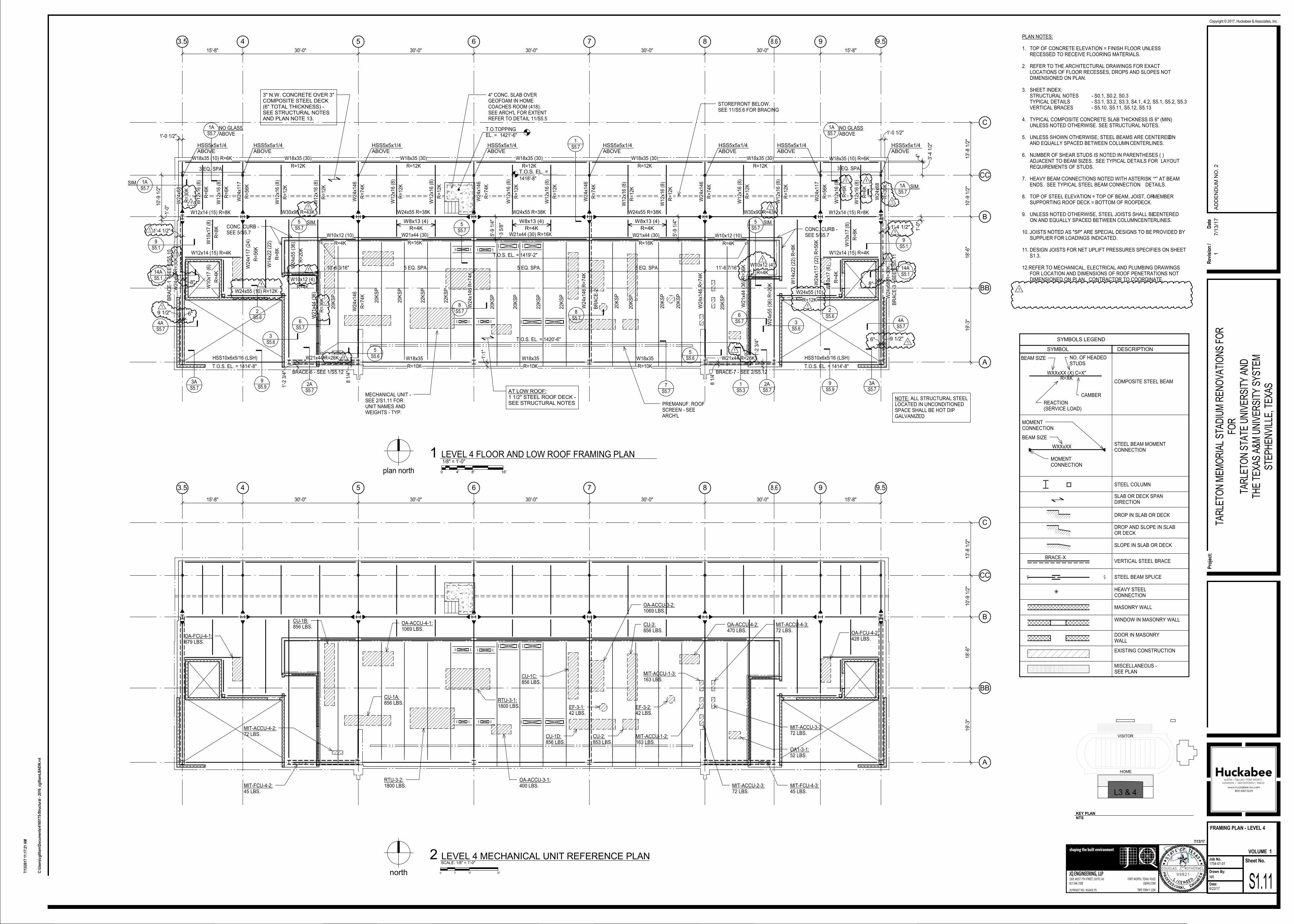
4" CONC. SLAB OVERGEOFOAM IN HOMECOACHES ROOM (418).SEE ARCH'L FOR EXTENTREFER TO DETAIL 11/S5.5
5S5.7
SIM.CONC. CURB -SEE 5/S5.7
5S5.7
SIM.
CONC. CURB -SEE 5/S5.7
BRACE-6 - SEE 1/S5.12 BRACE-7 - SEE 2/S5.12
8.6
9S5.9
9S5.9
NOTE: ALL STRUCTURAL STEELLOCATED IN UNCONDITIONEDSPACE SHALL BE HOT DIPGALVANIZED
T.O.S. EL. = 1414'-8"
HSS10x6x5/16 (LSH)
T.O.S. EL. = 1414'-8"
MECHANICAL UNIT -SEE 2/S1.11 FORUNIT NAMES ANDWEIGHTS - TYP.
1
1
1
1
1
1
1
1
1
1
1 1
1
1
1'-4 1/2"1
8"
6" 9 1/2"1
9 1/2" 6"
1
8"
1
14AS5.114A
S5.1
PLAN NOTES:
1. TOP OF CONCRETE ELEVATION = FINISH FLOOR UNLESSRECESSED TO RECEIVE FLOORING MATERIALS.
2. REFER TO THE ARCHITECTURAL DRAWINGS FOR EXACTLOCATIONS OF FLOOR RECESSES, DROPS AND SLOPES NOTDIMENSIONED ON PLAN.
3. SHEET INDEX:STRUCTURAL NOTES - S0.1, S0.2, S0.3TYPICAL DETAILS - S3.1, S3.2, S3.3, S4.1, 4.2, S5.1, S5.2, S5.3VERTICAL BRACES - S5.10, S5.11, S5.12, S5.13
4. TYPICAL COMPOSITE CONCRETE SLAB THICKNESS IS 6" (MIN)UNLESS NOTED OTHERWISE. SEE STRUCTURAL NOTES.
5. UNLESS SHOWN OTHERWISE, STEEL BEAMS ARE CENTERED ONAND EQUALLY SPACED BETWEEN COLUMN CENTERLINES.
6. NUMBER OF SHEAR STUDS IS NOTED IN PARENTHESES ( )ADJACENT TO BEAM SIZES. SEE TYPICAL DETAILS FOR LAYOUTREQUIREMENTS OF STUDS.
7. HEAVY BEAM CONNECTIONS NOTED WITH ASTERISK “*” AT BEAMENDS. SEE TYPICAL STEEL BEAM CONNECTION DETAILS.
8. TOP OF STEEL ELEVATION = TOP OF BEAM, JOIST, OR MEMBERSUPPORTING ROOF DECK = BOTTOM OF ROOF DECK.
9. UNLESS NOTED OTHERWISE, STEEL JOISTS SHALL BE CENTEREDON AND EQUALLY SPACED BETWEEN COLUMN CENTERLINES.
10. JOISTS NOTED AS "SP" ARE SPECIAL DESIGNS TO BE PROVIDED BYSUPPLIER FOR LOADINGS INDICATED.
11. DESIGN JOISTS FOR NET UPLIFT PRESSURES SPECIFIES ON SHEETS1.3.
12.REFER TO MECHANICAL, ELECTRICAL AND PLUMBING DRAWINGSFOR LOCATION AND DIMENSIONS OF ROOF PENETRATIONS NOTDIMENSIONED ON PLAN. CONTRACTOR TO COORDINATE.
WXXxXX (X) C=X"
BEAM SIZE
REACTION(SERVICE LOAD)
NO. OF HEADEDSTUDS
R=XK
CAMBER
SYMBOLS LEGEND
SYMBOL DESCRIPTION
COMPOSITE STEEL BEAM
MOMENTCONNECTION
MOMENTCONNECTION
WXXxXXSTEEL BEAM MOMENTCONNECTION
SLAB OR DECK SPANDIRECTION
DROP IN SLAB OR DECK
DROP AND SLOPE IN SLABOR DECK
SLOPE IN SLAB OR DECK
HEAVY STEELCONNECTION
EXISTING CONSTRUCTION
MASONRY WALL
STEEL COLUMN
STEEL BEAM SPLICE
MISCELLANEOUS -SEE PLAN
WINDOW IN MASONRY WALL
DOOR IN MASONRYWALL
BRACE-XVERTICAL STEEL BRACE
BEAM SIZE
4 5 6 7 8 9
C
A
B
9.53.5
CC
BB
8.6
RTU-3-2:1800 LBS.
RTU-3-1:1800 LBS.
CU-1B:856 LBS. CU-3:
856 LBS.OA-FCU-4-1:679 LBS.
MIT-ACCU-1-2:163 LBS.
MIT-ACCU-1-3:163 LBS.
MIT-ACCU-2-3:72 LBS.
MIT-ACCU-4-3:72 LBS.
MIT-ACCU-3-3:72 LBS.
CU-1A:856 LBS.
OA-ACCU-4-1:1069 LBS.
MIT-ACCU-4-2:72 LBS.
OA-ACCU-3-1:400 LBS.MIT-FCU-4-2:
45 LBS.
CU-2:853 LBS.
CU-1D:856 LBS.
OA-ACCU-3-2:1069 LBS.
CU-1C:856 LBS.
EF-3-1:42 LBS.
EF-3-2:42 LBS.
OA1-3-1:52 LBS.
MIT-FCU-4-3:45 LBS.
OA-ACCU-4-2:470 LBS. OA-FCU-4-2:
428 LBS.
15'-8" 30'-0" 30'-0" 30'-0" 30'-0" 30'-0" 15'-8"
19'-3
"18'-6
"10'-9
1/2
"13'-8
1/2
"
DOUGLAS J. ROTHERMEL
99821
1301 WEST 7TH STREET, SUITE 141
817.546.7200
FORT WORTH, TEXAS 76102
TBPE FIRM F-1294
JQ ENGINEERING, LLP
JQENG.COM
JQ PROJECT NO:
shaping the built environment
Sheet No.Job No.
Drawn By:
Date:
Pro
ject
:
Copyright © 2017, Huckabee & Associates, Inc.
VOLUME
4160175
7/13/17
C:\
Use
rs\c
gill
iam
\Do
cum
ents
\416
0175
-Str
uct
ura
l - 2
016_
cgill
iam
LB
AE
W.r
vt
7/13
/201
7 11
:17:
21 A
M
NR
S1.11
FRAMING PLAN - LEVEL 4
6/22/17
1754-01-01
TAR
LETO
N M
EM
OR
IAL
STA
DIU
M R
EN
OV
ATI
ON
S F
OR
FOR
TAR
LETO
N S
TATE
UN
IVE
RS
ITY
AN
DTH
E T
EX
AS
A&
M U
NIV
ER
SIT
Y S
YS
TEM
STE
PH
EN
VIL
LE, T
EX
AS
1
0 4' 8' 16'plan north
1/8" = 1'-0"LEVEL 4 FLOOR AND LOW ROOF FRAMING PLAN1
HOME
KEY PLAN
NTS
L3 & 4
VISITOR
000 5' 10' 20'north
SCALE: 1/8" = 1'-0"
2 LEVEL 4 MECHANICAL UNIT REFERENCE PLAN
1
Rev
isio
n /
Dat
e
17/1
3/1
7A
DD
EN
DU
M N
O. 2
4 5 6 7 8 9
C
A
B
15'-8" 30'-0" 30'-0" 30'-0" 30'-0" 30'-0" 15'-8"
19'-3
"18'-6
"10'-9
1/2
"13'-8
1/2
"
1 1/2" STEEL ROOF DECK -SEE STRUCTURAL NOTES
9.53.5
CC
W12x16 R=4K
W12x30
R=8K
W12x16 R=4K W12x16 R=4K W10x22 R=4KW12x16 R=4KW12x16 R=4KW10x22 R=4K
W14x22
R=4K
W14x22
R=4K
W14x22
R=4K
W1
6x2
6 R
=8
K
10
K1
24
KS
P
W1
6x2
6 R
=8
K
HS
S12
x6x3
/8 (
LS
V)
R=
8K
W16x26
R=6K
10
K1
10
K1
W1
4x3
8
R=
16
K
W1
4x3
8
R=
6K
10
K1
10
K1
10
K1
10
K1
W1
4x3
8
R=
16
K
W12x30
R=8K
W21x50
R=14K
W12x19
R=4K
W12x30
R=8K
10
K1
10
K1
10
K1
10
K1
W21x44
R=14K
W1
4x3
8
R=
16
K
W1
4x3
8
R=
16
K
W1
4x3
8
R=
16
K
W1
4x3
8
R=
16
K
10
K1
10
K1
10
K1
10
K1
W21x44
R=14K
W12x30
R=8K
10
K1
10
K1
10
K1
10
K1
W21x44
R=14K
W12x30
R=8K
W21x50
R=14K
10
K1
10
K1
10
K1
10
K1
W1
4x3
8
R=
16
K
10
K1
W12x19
R=4K
10
K1
W1
4x3
8
R=
6K
W16x26
R=6K
W1
6x2
6
R=
8K
24
KS
P
24
K6
24
K6
HS
S12
x6x3
/8 (
LS
V)
R=
8K
W12x19 R=6K
W16x26 R=10K (HIGH) W16x26 R=10K (HIGH)
W12x19 R=6K
W1
6x2
6
R=
8K
24
K6
24
K6
5 EQ. SPA.EQ EQ
5 EQ. SPA. 5 EQ. SPA. 5 EQ. SPA.
5 EQ. SPA.
3 EQ. SPA.
10K1 10K1 10K1 10K1
BB
BR
AC
E-1
BR
AC
E-3
W1
4x3
8
R=
16
K
10'-0
1/8
"2 1
19/1
28
"
5'-1"
4'-1
0 3
/4"
1'-1"
4"
6'-3
"
5'-1"
1'-3"
4'-1
0 3
/4"
2.5K12.5K12.5K1
1S5.8
TYP.
2S5.8
3S5.8
10S5.2
2S5.3
TYP.
1S5.3
10S5.2
2S5.8
3S5.8
T.O.S. EL. = 1432 11T.O.S. EL. = 1432 11
14
K1
W8
x31
10
K1
14
K1
W8
x31
R=
4K
191'-6"
62'-3"
10'-6"
4/S5.8EA. END
4/S5.8EA. END
10'-6"
T.O.S. EL. = 1432'-0 1/4"
T.O.S. EL. = 1432'-2"
T.O.S. EL. = 1432'-10 3/4"
W10x17 R=4K
W10x17 R=4K W10x17 R=4K
W10x17
R=4K
8.6
BRACE-7BRACE-6
W1
0x1
2
R=
6K
W1
0x1
2
R=
6K
10
K1
10
K1
10
K1
10
K1
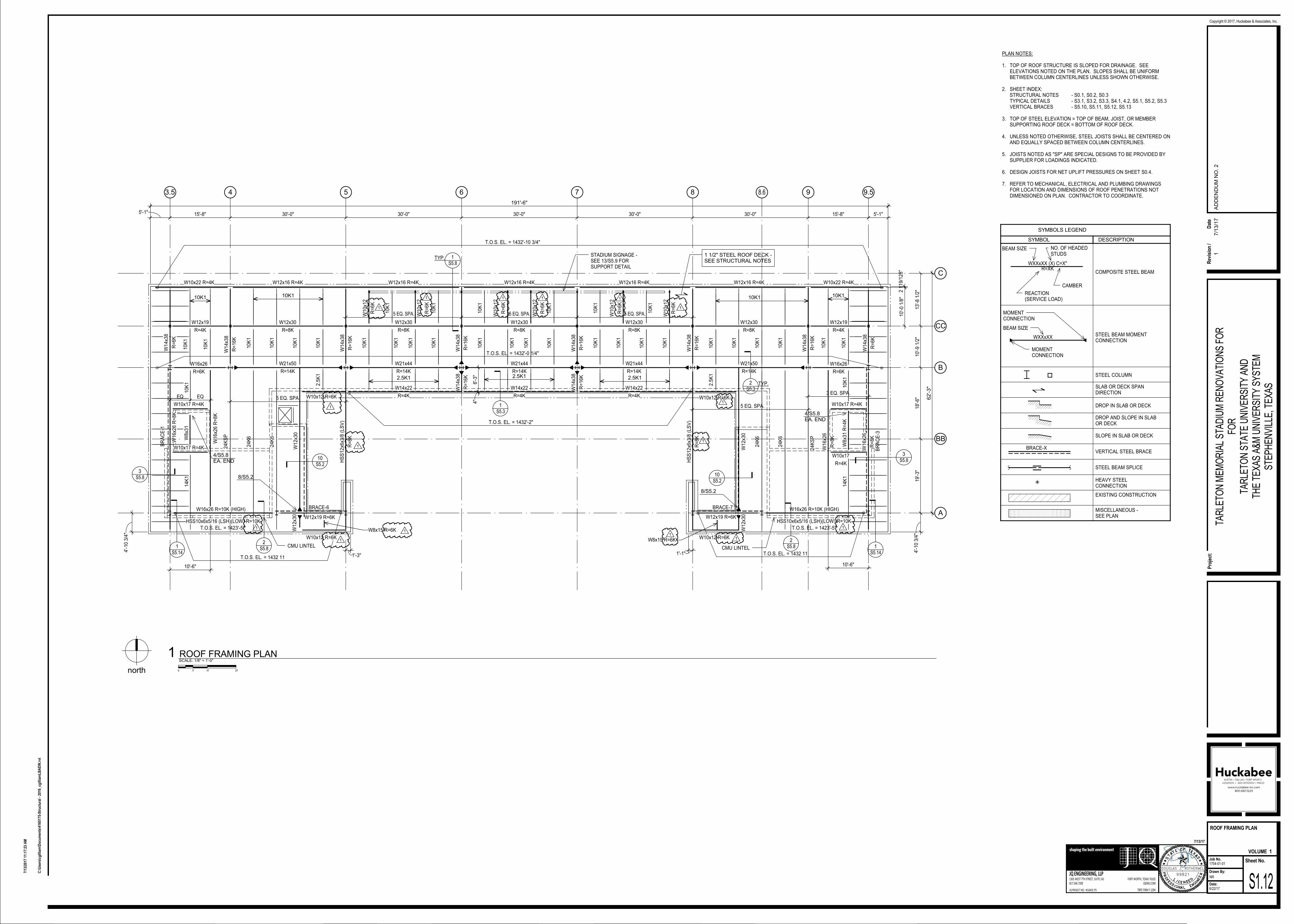
STADIUM SIGNAGE -SEE 13/S5.9 FORSUPPORT DETAIL
10
K1
10
K1
W1
0x1
2
R=
6K
W1
0x1
2
R=
6K
W1
0x1
2
R=
6K
W1
0x1
2
R=
6K
HSS10x6x5/16 (LSH)(LOW) R=10K
CMU LINTEL
HSS10x6x5/16 (LSH)(LOW) R=10K
CMU LINTEL
T.O.S. EL. = 1423'-5" T.O.S. EL. = 1423'-5"
W1
2x3
0W
12x3
0
8/S5.2
W10x12 R=6K
W8x15 R=6K
2.5
K1
2.5
K1
W10x12 R=6KW8x15 R=6K
W1
2x3
0W
12x3
0
W10x12 R=6K W10x12 R=6K
8/S5.2
1S5.14
1S5.14
1
1
1
1
1
1
1
1 1
1
1
11
1
1
PLAN NOTES:
1. TOP OF ROOF STRUCTURE IS SLOPED FOR DRAINAGE. SEEELEVATIONS NOTED ON THE PLAN. SLOPES SHALL BE UNIFORMBETWEEN COLUMN CENTERLINES UNLESS SHOWN OTHERWISE.
2. SHEET INDEX:STRUCTURAL NOTES - S0.1, S0.2, S0.3TYPICAL DETAILS - S3.1, S3.2, S3.3, S4.1, 4.2, S5.1, S5.2, S5.3VERTICAL BRACES - S5.10, S5.11, S5.12, S5.13
3. TOP OF STEEL ELEVATION = TOP OF BEAM, JOIST, OR MEMBERSUPPORTING ROOF DECK = BOTTOM OF ROOF DECK.
4. UNLESS NOTED OTHERWISE, STEEL JOISTS SHALL BE CENTERED ONAND EQUALLY SPACED BETWEEN COLUMN CENTERLINES.
5. JOISTS NOTED AS "SP" ARE SPECIAL DESIGNS TO BE PROVIDED BYSUPPLIER FOR LOADINGS INDICATED.
6. DESIGN JOISTS FOR NET UPLIFT PRESSURES ON SHEET S0.4.
7. REFER TO MECHANICAL, ELECTRICAL AND PLUMBING DRAWINGSFOR LOCATION AND DIMENSIONS OF ROOF PENETRATIONS NOTDIMENSIONED ON PLAN. CONTRACTOR TO COORDINATE.
WXXxXX (X) C=X"
BEAM SIZE
REACTION(SERVICE LOAD)
NO. OF HEADEDSTUDS
R=XK
CAMBER
SYMBOLS LEGEND
SYMBOL DESCRIPTION
COMPOSITE STEEL BEAM
MOMENTCONNECTION
MOMENTCONNECTION
WXXxXXSTEEL BEAM MOMENTCONNECTION
SLAB OR DECK SPANDIRECTION
DROP IN SLAB OR DECK
DROP AND SLOPE IN SLABOR DECK
SLOPE IN SLAB OR DECK
HEAVY STEELCONNECTION
EXISTING CONSTRUCTION
STEEL COLUMN
STEEL BEAM SPLICE
MISCELLANEOUS -SEE PLAN
BRACE-XVERTICAL STEEL BRACE
BEAM SIZE
DOUGLAS J. ROTHERMEL
99821
1301 WEST 7TH STREET, SUITE 141
817.546.7200
FORT WORTH, TEXAS 76102
TBPE FIRM F-1294
JQ ENGINEERING, LLP
JQENG.COM
JQ PROJECT NO:
shaping the built environment
Sheet No.Job No.
Drawn By:
Date:
Pro
ject
:
Copyright © 2017, Huckabee & Associates, Inc.
VOLUME
4160175
7/13/17
C:\
Use
rs\c
gill
iam
\Do
cum
ents
\416
0175
-Str
uct
ura
l - 2
016_
cgill
iam
LB
AE
W.r
vt
7/13
/201
7 11
:17:
23 A
M
NR
S1.12
ROOF FRAMING PLAN
6/22/17
1754-01-01
TAR
LETO
N M
EM
OR
IAL
STA
DIU
M R
EN
OV
ATI
ON
S F
OR
FOR
TAR
LETO
N S
TATE
UN
IVE
RS
ITY
AN
DTH
E T
EX
AS
A&
M U
NIV
ER
SIT
Y S
YS
TEM
STE
PH
EN
VIL
LE, T
EX
AS
1
000 5' 10' 20'north
SCALE: 1/8" = 1'-0"
1 ROOF FRAMING PLAN
1
Rev
isio
n /
Dat
e
17/1
3/1
7A
DD
EN
DU
M N
O. 2
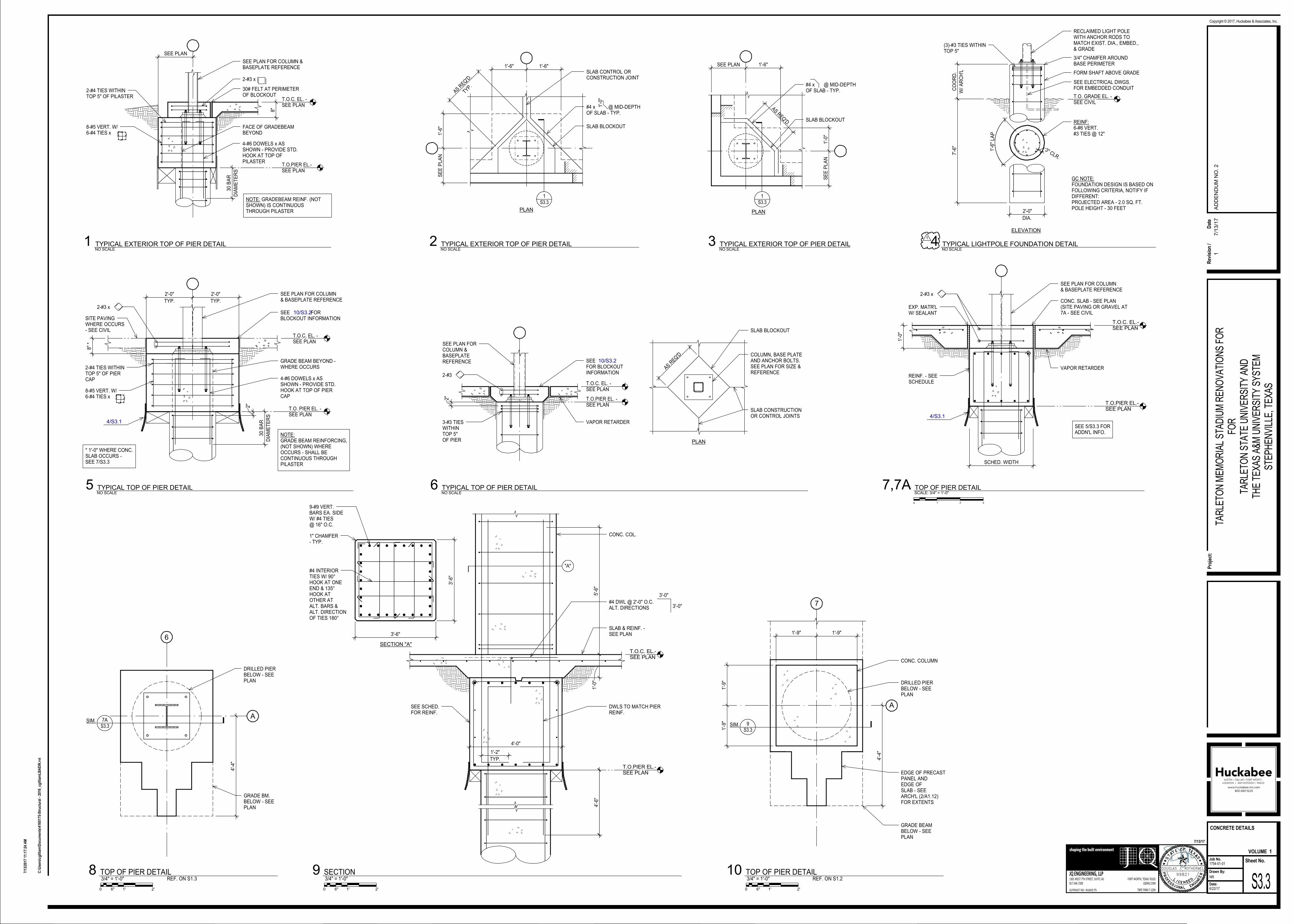
T.O.C. EL.-SEE PLAN
T.O.PIER EL.-SEE PLAN
T.O.PIER EL.-SEE PLAN
T.O.C. EL.-SEE PLAN
2'-
9 3
/4"
5'-6
"1'-0
"
4'-0"
SEE SCHED.FOR REINF.
SLAB & REINF. -SEE PLAN
CONC. COL.
TYP.
1'-2"
DWLS TO MATCH PIERREINF.
4'-6
"
1" CHAMFER- TYP.
9-#9 VERT.BARS EA. SIDEW/ #4 TIES@ 16" O.C.
#4 INTERIORTIES W/ 90°HOOK AT ONEEND & 135°HOOK ATOTHER ATALT. BARS &ALT. DIRECTIONOF TIES 180°
3'-6
"
3'-6"
SECTION "A"
"A"
#4 DWL @ 2'-0" O.C.ALT. DIRECTIONS
3'-0"
3'-0"
T.O.C. EL. -SEE PLAN
T.O.PIER EL.-SEE PLAN
SEE PLAN FOR COLUMN &BASEPLATE REFERENCE
NOTE: GRADEBEAM REINF. (NOTSHOWN) IS CONTINUOUSTHROUGH PILASTER
8-#5 VERT. W/6-#4 TIES x
2-#4 TIES WITHINTOP 5" OF PILASTER
FACE OF GRADEBEAMBEYOND
2-#3 x
30# FELT AT PERIMETEROF BLOCKOUT
4-#6 DOWELS x ASSHOWN - PROVIDE STD.HOOK AT TOP OFPILASTER
8"
SEE PLAN
DIA
ME
TE
RS
30
BA
R
#4 x @ MID-DEPTHOF SLAB - TYP.
PLAN
SLAB BLOCKOUT
SLAB CONTROL ORCONSTRUCTION JOINT
1'-0
"
1'-6" 1'-6"
1'-6
"S
EE
PL
AN
TYP.AS R
EQ'D
.
1S3.3
PLAN
#4 x @ MID-DEPTHOF SLAB - TYP.
SLAB BLOCKOUT
SE
E P
LA
N1'-0
"
SEE PLAN 1'-6"
AS REQ'D.
1S3.3
T.O. PIER EL. -SEE PLAN
T.O.C. EL. -SEE PLAN
SEE FORBLOCKOUT INFORMATION
2-#3 x .
SEE PLAN FOR COLUMN& BASEPLATE REFERENCE
2-#4 TIES WITHINTOP 5" OF PIERCAP 4-#6 DOWELS x AS
SHOWN - PROVIDE STD.HOOK AT TOP OF PIERCAP
DIA
ME
TE
RS
30
BA
R
8"
*
2"
8-#5 VERT. W/6-#4 TIES x
TYP.
2'-0"
TYP.
2'-0"
10/S3.2SITE PAVINGWHERE OCCURS- SEE CIVIL
4/S3.1
GRADE BEAM BEYOND -WHERE OCCURS
NOTE:GRADE BEAM REINFORCING,(NOT SHOWN) WHEREOCCURS - SHALL BECONTINUOUS THROUGHPILASTER
* 1'-0" WHERE CONC.SLAB OCCURS -SEE 7/S3.3
T.O.PIER EL. -SEE PLAN
T.O.C. EL. -SEE PLAN
SEE PLAN FORCOLUMN &BASEPLATEREFERENCE
3-#3 TIESWITHINTOP 5"OF PIER
2-#3 .
VAPOR RETARDER
SEEFOR BLOCKOUTINFORMATION
2"
10/S3.2COLUMN, BASE PLATEAND ANCHOR BOLTS.SEE PLAN FOR SIZE &REFERENCE
SLAB BLOCKOUT
SLAB CONSTRUCTIONOR CONTROL JOINTS
PLAN
AS REQ
'D
CONC. SLAB - SEE PLAN(SITE PAVING OR GRAVEL AT7A - SEE CIVIL
2-#3 x .
SEE PLAN FOR COLUMN& BASEPLATE REFERENCE
REINF. - SEESCHEDULE
EXP. MATR'LW/ SEALANT
4/S3.1
VAPOR RETARDER
SEE 5/S3.3 FORADDN'L INFO.
1'-0
"
SCHED. WIDTH
4'-4
"
7
A
DRILLED PIERBELOW - SEEPLAN
CONC. COLUMN
EDGE OF PRECASTPANEL ANDEDGE OFSLAB - SEEARCH'L (2/A1.12)FOR EXTENTS
9S3.3
SIM.
GRADE BEAMBELOW - SEEPLAN
1'-9" 1'-9"
1'-9
"1'-9
"
6
A
DRILLED PIERBELOW - SEEPLAN
GRADE BM.BELOW - SEEPLAN
4'-4
"
7AS3.3
SIM.
7/S3.3
SEE ELECTRICAL DWGS.FOR EMBEDDED CONDUIT
FORM SHAFT ABOVE GRADE
ELEVATION
REINF:6-#6 VERT.#3 TIES @ 12"
3/4" CHAMFER AROUNDBASE PERIMETER
RECLAIMED LIGHT POLEWITH ANCHOR RODS TOMATCH EXIST. DIA., EMBED.,& GRADE
GC NOTE:FOUNDATION DESIGN IS BASED ONFOLLOWING CRITERIA, NOTIFY IFDIFFERENT:PROJECTED AREA - 2.0 SQ. FT.POLE HEIGHT - 30 FEET
T.O. GRADE EL. -SEE CIVIL
W/
AR
CH
'L
CO
OR
D.
-
DIA.
-
1'-6
" LA
P
3" CLR.
(3)-#3 TIES WITHINTOP 5"
2'-0"
7'-6
"
DOUGLAS J. ROTHERMEL
99821
1301 WEST 7TH STREET, SUITE 141
817.546.7200
FORT WORTH, TEXAS 76102
TBPE FIRM F-1294
JQ ENGINEERING, LLP
JQENG.COM
JQ PROJECT NO:
shaping the built environment
Sheet No.Job No.
Drawn By:
Date:
Pro
ject
:
Copyright © 2017, Huckabee & Associates, Inc.
VOLUME
4160175
7/13/17
C:\
Use
rs\c
gill
iam
\Do
cum
ents
\416
0175
-Str
uct
ura
l - 2
016_
cgill
iam
LB
AE
W.r
vt
7/13
/201
7 11
:17:
24 A
M
NR
S3.3
CONCRETE DETAILS
6/22/17
1754-01-01
TAR
LETO
N M
EM
OR
IAL
STA
DIU
M R
EN
OV
ATI
ON
S F
OR
FOR
TAR
LETO
N S
TATE
UN
IVE
RS
ITY
AN
DTH
E T
EX
AS
A&
M U
NIV
ER
SIT
Y S
YS
TEM
STE
PH
EN
VIL
LE, T
EX
AS
1
0 2'6" 1'
3/4" = 1'-0"SECTION9
NO SCALE
1 TYPICAL EXTERIOR TOP OF PIER DETAILNO SCALE
2 TYPICAL EXTERIOR TOP OF PIER DETAILNO SCALE
3 TYPICAL EXTERIOR TOP OF PIER DETAIL
NO SCALE
5 TYPICAL TOP OF PIER DETAILNO SCALE
6 TYPICAL TOP OF PIER DETAIL
000 1' 2' 3'
SCALE: 3/4" = 1'-0"TOP OF PIER DETAIL7,7A
0 2'6" 1'
3/4" = 1'-0"TOP OF PIER DETAIL10
REF. ON S1.2
0 2'6" 1'
3/4" = 1'-0"TOP OF PIER DETAIL8
REF. ON S1.3
NO SCALE
4 TYPICAL LIGHTPOLE FOUNDATION DETAIL1
Rev
isio
n /
Dat
e
17/1
3/1
7A
DD
EN
DU
M N
O. 2
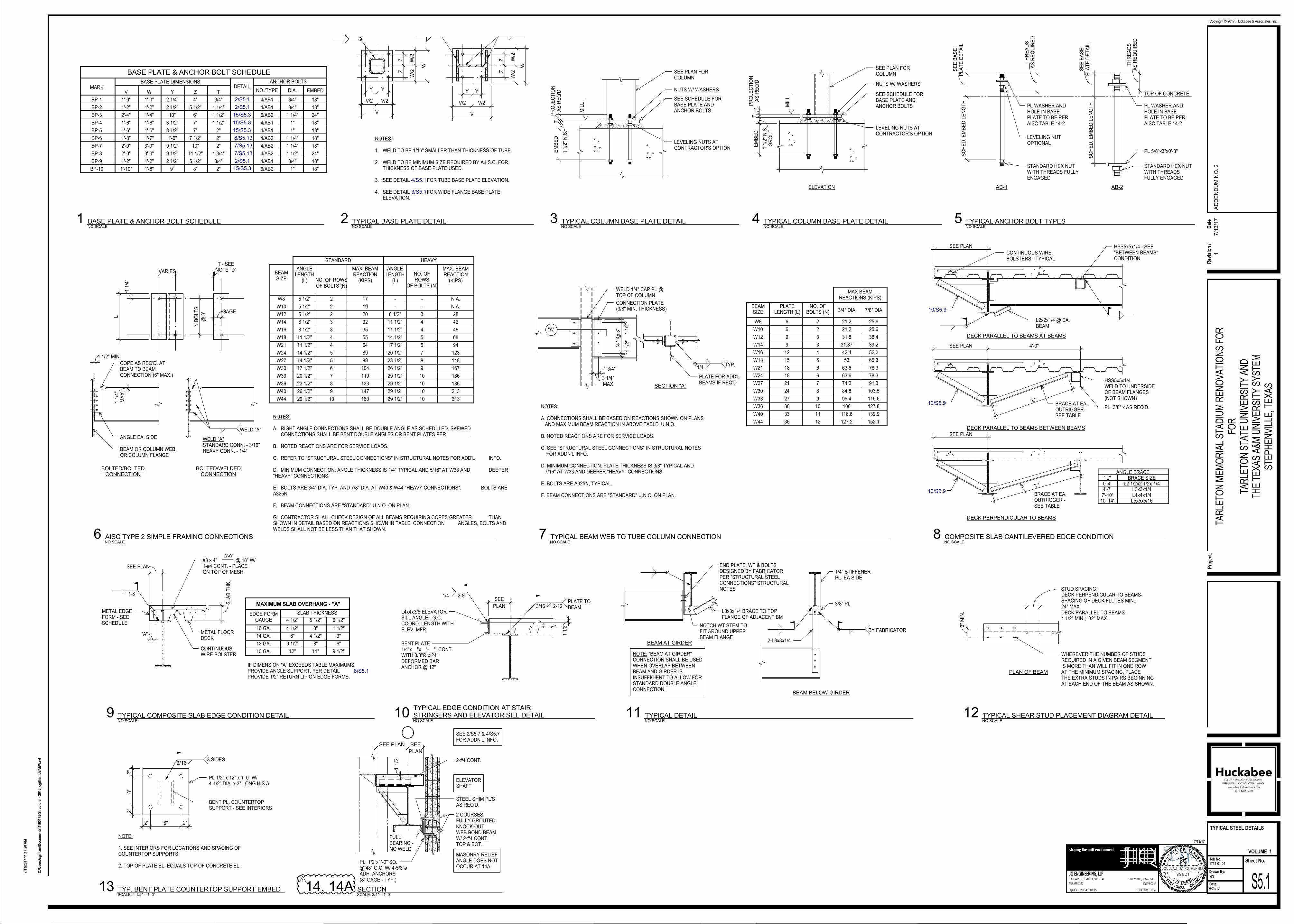
BASE PLATE & ANCHOR BOLT SCHEDULE
BASE PLATE DIMENSIONSMARK
WV Y Z T DIA.NO./TYPE EMBED
ANCHOR BOLTSDETAIL
1'-0"1'-0" 2 1/4" 4" 3/4"BP-1 2/S5.1 4/AB1 3/4" 18"
1'-2"1'-2" 2 1/2" 5 1/2" 1 1/4"BP-2 2/S5.1 4/AB1 3/4" 18"
1'-4"2'-4" 10" 6" 1 1/2"BP-3 15/S5.3 6/AB2 1 1/4" 24"
1'-6"1'-6" 3 1/2" 7" 1 1/2"BP-4 15/S5.3 4/AB1 1" 18"
1'-6"1'-6" 3 1/2" 7" 2"BP-5 15/S5.3 4/AB1 1" 18"
1'-7"1'-8" 1'-0" 7 1/2" 2"BP-6 6/S5.13 4/AB2 1 1/4" 18"
3'-0"2'-0" 9 1/2" 10" 2"BP-7 7/S5.13 4/AB2 1 1/4" 18"
3'-0"2'-0" 9 1/2" 11 1/2" 1 3/4"BP-8 7/S5.13 4/AB2 1 1/2" 24"
1'-2"1'-2" 2 1/2" 5 1/2" 3/4"BP-9 2/S5.1 4/AB1 3/4" 18"
1'-8"1'-10" 9" 8" 2"BP-10 6/AB2 1" 18"15/S5.3
NOTES:
1. WELD TO BE 1/16" SMALLER THAN THICKNESS OF TUBE.
2. WELD TO BE MINIMUM SIZE REQUIRED BY A.I.S.C. FORTHICKNESS OF BASE PLATE USED.
3. SEE DETAIL FOR TUBE BASE PLATE ELEVATION.
4. SEE DETAIL FOR WIDE FLANGE BASE PLATEELEVATION.
Y Y
V/2 V/2
V
ZZ
W/2
W/2
W
.
4/S5.1
Y Y
V/2 V/2
V
ZZ
W/2
W/2
W
..
.
3/S5.1
MIL
L
SEE PLAN FORCOLUMN
SEE SCHEDULE FORBASE PLATE ANDANCHOR BOLTS
NUTS W/ WASHERS
LEVELING NUTS ATCONTRACTOR'S OPTION
AS
RE
Q'D
PR
OJE
CT
ION
T
GR
OU
T1 1
/2"
N.S
.
EM
BE
D
ELEVATION
STANDARD HEX NUTWITH THREADSFULLY ENGAGED
PL 5/8"x3"x0'-3"
AB-2
PL WASHER ANDHOLE IN BASEPLATE TO BE PERAISC TABLE 14-2
AB-1
STANDARD HEX NUTWITH THREADS FULLYENGAGED
TOP OF CONCRETE
AS
RE
QU
IRE
DT
HR
EA
DS
PL
AT
E D
ET
AIL
SE
E B
AS
E
SC
HE
D.
EM
BE
D L
EN
GT
H
SC
HE
D.
EM
BE
D L
EN
GT
H
AS
RE
QU
IRE
DT
HR
EA
DS
PL
AT
E D
ET
AIL
SE
E B
AS
E
LEVELING NUTOPTIONAL
PL WASHER ANDHOLE IN BASEPLATE TO BE PERAISC TABLE 14-2
BEAMSIZE
ANGLELENGTH
(L)
NO. OFROWS
OF BOLTS (N)
STANDARD HEAVY
W8 5 1/2" 2 - -
W12 8 1/2" 3
8 1/2"W14 3 11 1/2" 4
11 1/2"W18 4 14 1/2" 5
W21 17 1/2" 5
14 1/2"W24 5 20 1/2" 7
W27 23 1/2" 8
17 1/2"W30 6 26 1/2" 9
20 1/2"W33 7 29 1/2" 10
23 1/2"W36 8
26 1/2"W40 9
29 1/2"W44 10
COPE AS REQ'D. ATBEAM TO BEAMCONNECTION (6" MAX.)
BEAM OR COLUMN WEB,OR COLUMN FLANGE
BOLTED/BOLTEDCONNECTION
BOLTED/WELDEDCONNECTION
133
119
104
89
89
64
55
35
32
20
19
17
167
148
186
186
46
123
94
68
42
28
N.A.
N.A.
160
147
213
213
NOTES:
A. RIGHT ANGLE CONNECTIONS SHALL BE DOUBLE ANGLE AS SCHEDULED. SKEWED CONNECTIONS SHALL BE BENT DOUBLE ANGLES OR BENT PLATES PER .
B. NOTED REACTIONS ARE FOR SERVICE LOADS.
C. REFER TO "STRUCTURAL STEEL CONNECTIONS" IN STRUCTURAL NOTES FOR ADD'L INFO.
D. MINIMUM CONNECTION: ANGLE THICKNESS IS 1/4" TYPICAL AND 5/16" AT W33 AND DEEPER"HEAVY" CONNECTIONS.
E. BOLTS ARE 3/4" DIA. TYP. AND 7/8" DIA. AT W40 & W44 "HEAVY CONNECTIONS". BOLTS AREA325N.
F. BEAM CONNECTIONS ARE "STANDARD" U.N.O. ON PLAN.
G. CONTRACTOR SHALL CHECK DESIGN OF ALL BEAMS REQUIRING COPES GREATER THANSHOWN IN DETAIL BASED ON REACTIONS SHOWN IN TABLE. CONNECTION ANGLES, BOLTS ANDWELDS SHALL NOT BE LESS THAN THAT SHOWN.
W16 11 1/2" 4
W10 - -
MAX. BEAMREACTION
(KIPS)
ANGLE EA. SIDE WELD "A"STANDARD CONN. - 3/16"HEAVY CONN. - 1/4"
1 1
/4"
L
VARIES
@ 3
"
N B
OLT
S
GAGE
NOTE "D"T - SEE
1 1/2" MIN.
MA
X1 1
/4"
.
WELD "A"..
5 1/2" 2
8 1/2" 3
11 1/2" 4
14 1/2" 5
5 1/2" 2
29 1/2" 10
29 1/2" 10
29 1/2" 10
ANGLELENGTH
(L) NO. OF ROWSOF BOLTS (N)
MAX. BEAMREACTION
(KIPS)
DECK PERPENDICULAR TO BEAMS
DECK PARALLEL TO BEAMS BETWEEN BEAMS
-
HSS5x5x1/4WELD TO UNDERSIDEOF BEAM FLANGES(NOT SHOWN)
BRACE AT EA.OUTRIGGER -SEE TABLE
L2x2x1/4 @ EA.BEAM
HSS5x5x1/4 - SEE"BETWEEN BEAMS"CONDITION
CONTINUOUS WIREBOLSTERS - TYPICAL
SEE PLAN
SEE PLAN 4'-0"
SEE PLAN
.
.
DECK PARALLEL TO BEAMS AT BEAMS
-
-
"L"
BRACE AT EA.OUTRIGGER -SEE TABLE
"L"
10'-14'7'-10'
BRACE SIZE
4'-7'0'-4' L2 1/2x2 1/2x 1/4
L5x5x5/16L4x4x1/4L3x3x1/4
ANGLE BRACE
PL. 3/8" x AS REQ'D.
" L"
10/S5.9
10/S5.9
10/S5.9
MAXIMUM SLAB OVERHANG - "A"
IF DIMENSION "A" EXCEEDS TABLE MAXIMUMS,PROVIDE ANGLE SUPPORT, PER DETAIL .PROVIDE 1/2" RETURN LIP ON EDGE FORMS.
11"
3"
4 1/2"
8"
SLAB THICKNESS
5 1/2"
METAL FLOORDECK
#3 x 4" @ 18" W/1-#4 CONT. - PLACEON TOP OF MESH
METAL EDGEFORM - SEESCHEDULE
4 1/2"16 GA.
10 GA.
12 GA.
14 GA. 6"
9 1/2"
12"
EDGE FORMGAUGE
3'-0"
4 1/2"
1 1/2"
9 1/2"
3"
6"
6 1/2"
CONTINUOUSWIRE BOLSTER
SEE PLAN
"A"
SL
AB
TH
K.
1-8.
8/S5.1
BENT PLATE1/4"x__"x__'-__" CONT.WITH 3/8"Ø x 24"DEFORMED BARANCHOR @ 12"
L4x4x3/8 ELEVATORSILL ANGLE - G.C.COORD. LENGTH WITHELEV. MFR.
PLAN
SEE
1 1
/2"
1/4 2-8
3/16 2-12. PLATE TO
BEAM
.
1/4" STIFFENERPL- EA SIDE
BEAM BELOW GIRDER
BEAM AT GIRDER
NOTCH WT STEM TOFIT AROUND UPPERBEAM FLANGE
END PLATE, WT & BOLTSDESIGNED BY FABRICATORPER "STRUCTURAL STEELCONNECTIONS" STRUCTURALNOTES
L3x3x1/4 BRACE TO TOPFLANGE OF ADJACENT BM
3/8" PL
2-L3x3x1/4
NOTE: "BEAM AT GIRDER"CONNECTION SHALL BE USEDWHEN OVERLAP BETWEENBEAM AND GIRDER ISINSUFFICIENT TO ALLOW FORSTANDARD DOUBLE ANGLECONNECTION.
.
.
BY FABRICATOR.
PLAN OF BEAM
WHEREVER THE NUMBER OF STUDSREQUIRED IN A GIVEN BEAM SEGMENTIS MORE THAN WILL FIT IN ONE ROWAT THE MINIMUM SPACING, PLACETHE EXTRA STUDS IN PAIRS BEGINNINGAT EACH END OF THE BEAM AS SHOWN.
DECK PERPENDICULAR TO BEAMS-SPACING OF DECK FLUTES MIN.;24" MAX.DECK PARALLEL TO BEAMS-4 1/2" MIN.; 32" MAX.
3"
MIN
.
STUD SPACING:
MIL
L
SEE PLAN FORCOLUMN
SEE SCHEDULE FORBASE PLATE ANDANCHOR BOLTS
NUTS W/ WASHERS
LEVELING NUTS ATCONTRACTOR'S OPTION
EM
BE
D
1 1
/2"
N.S
.
TA
S R
EQ
'DP
RO
JEC
TIO
N
"A"
SECTION "A"
PLATE FOR ADD'LBEAMS IF REQ'D
WELD 1/4" CAP PL @TOP OF COLUMN
CONNECTION PLATE(3/8" MIN. THICKNESS)
BEAMSIZE
PLATELENGTH (L)
NO. OFBOLTS (N) 3/4" DIA 7/8" DIA
W8 6 2 21.2 25.6
W12
W14
W18
W21
W24
W27
W30
W33
W36
W40
W44
W16
W10
NOTES:
A. CONNECTIONS SHALL BE BASED ON REACTIONS SHOWN ON PLANS AND MAXIMUM BEAM REACTION IN ABOVE TABLE, U.N.O.
B. NOTED REACTIONS ARE FOR SERVICE LOADS.
C. SEE "STRUCTURAL STEEL CONNECTIONS" IN STRUCTURAL NOTES FOR ADDN'L INFO.
D. MINIMUM CONNECTION: PLATE THICKNESS IS 3/8" TYPICAL AND 7/16" AT W33 AND DEEPER "HEAVY" CONNECTIONS.
E. BOLTS ARE A325N, TYPICAL.
F. BEAM CONNECTIONS ARE "STANDARD" U.N.O. ON PLAN.
9 3 31.8 38.4
31.87 39.2
12 4 42.4 52.2
15 5 53 65.3
18 6 63.6 78.3
21 7 74.2 91.3
24 8 84.8 103.5
27 9 95.4 115.6
30 10 106 127.8
33 11 116.6 139.9
36 12 127.2 152.1
MAX BEAMREACTIONS (KIPS)
1 1
/2"
N-1
@ 3
"
1 1
/2"
MAX3 1/4"
1 3/4" 1/4.
TYP.
6 2 21.2 25.6
9 3
18 6 63.6 78.3
PL 1/2" x 12" x 1'-0" W/4-1/2" DIA. x 3" LONG H.S.A.
2" 8" 2"
2"
8"
2"
BENT PL. COUNTERTOPSUPPORT - SEE INTERIORS
3/163 SIDES
NOTE:
1. SEE INTERIORS FOR LOCATIONS AND SPACING OFCOUNTERTOP SUPPORTS
2. TOP OF PLATE EL. EQUALS TOP OF CONCRETE EL.
SEE PLAN
PLAN
SEE
2-#4 CONT.
ELEVATORSHAFT
SEE 2/S5.7 & 4/S5.7FOR ADDN'L INFO.
1 1
/2"
FULLBEARING -NO WELD
STEEL SHIM PL'SAS REQ'D.
2 COURSESFULLY GROUTEDKNOCK-OUTWEB BOND BEAMW/ 2-#4 CONT.TOP & BOT.
MASONRY RELIEFANGLE DOES NOTOCCUR AT 14A
PL, 1/2"x1'-0" SQ.@ 48" O.C. W/ 4-5/8"øADH. ANCHORS(8" GAGE - TYP.)
DOUGLAS J. ROTHERMEL
99821
1301 WEST 7TH STREET, SUITE 141
817.546.7200
FORT WORTH, TEXAS 76102
TBPE FIRM F-1294
JQ ENGINEERING, LLP
JQENG.COM
JQ PROJECT NO:
shaping the built environment
Sheet No.Job No.
Drawn By:
Date:
Pro
ject
:
Copyright © 2017, Huckabee & Associates, Inc.
VOLUME
4160175
7/13/17
C:\
Use
rs\c
gill
iam
\Do
cum
ents
\416
0175
-Str
uct
ura
l - 2
016_
cgill
iam
LB
AE
W.r
vt
7/13
/201
7 11
:17:
28 A
M
NR
S5.1
TYPICAL STEEL DETAILS
6/22/17
1754-01-01
TAR
LETO
N M
EM
OR
IAL
STA
DIU
M R
EN
OV
ATI
ON
S F
OR
FOR
TAR
LETO
N S
TATE
UN
IVE
RS
ITY
AN
DTH
E T
EX
AS
A&
M U
NIV
ER
SIT
Y S
YS
TEM
STE
PH
EN
VIL
LE, T
EX
AS
1
NO SCALE
1 BASE PLATE & ANCHOR BOLT SCHEDULENO SCALE
2 TYPICAL BASE PLATE DETAILNO SCALE
4 TYPICAL COLUMN BASE PLATE DETAILNO SCALE
5 TYPICAL ANCHOR BOLT TYPES
NO SCALE
6 AISC TYPE 2 SIMPLE FRAMING CONNECTIONSNO SCALE
8 COMPOSITE SLAB CANTILEVERED EDGE CONDITION
NO SCALE
9 TYPICAL COMPOSITE SLAB EDGE CONDITION DETAILNO SCALE
10TYPICAL EDGE CONDITION AT STAIRSTRINGERS AND ELEVATOR SILL DETAIL
NO SCALE
11 TYPICAL DETAILNO SCALE
12 TYPICAL SHEAR STUD PLACEMENT DIAGRAM DETAIL
NO SCALE
3 TYPICAL COLUMN BASE PLATE DETAIL
NO SCALE
7 TYPICAL BEAM WEB TO TUBE COLUMN CONNECTION
SCALE: 1 1/2" = 1'-0"
13 TYP. BENT PLATE COUNTERTOP SUPPORT EMBEDSCALE: 3/4" = 1'-0"
14, 14A SECTION
1
Rev
isio
n /
Dat
e
17/1
3/1
7A
DD
EN
DU
M N
O. 2
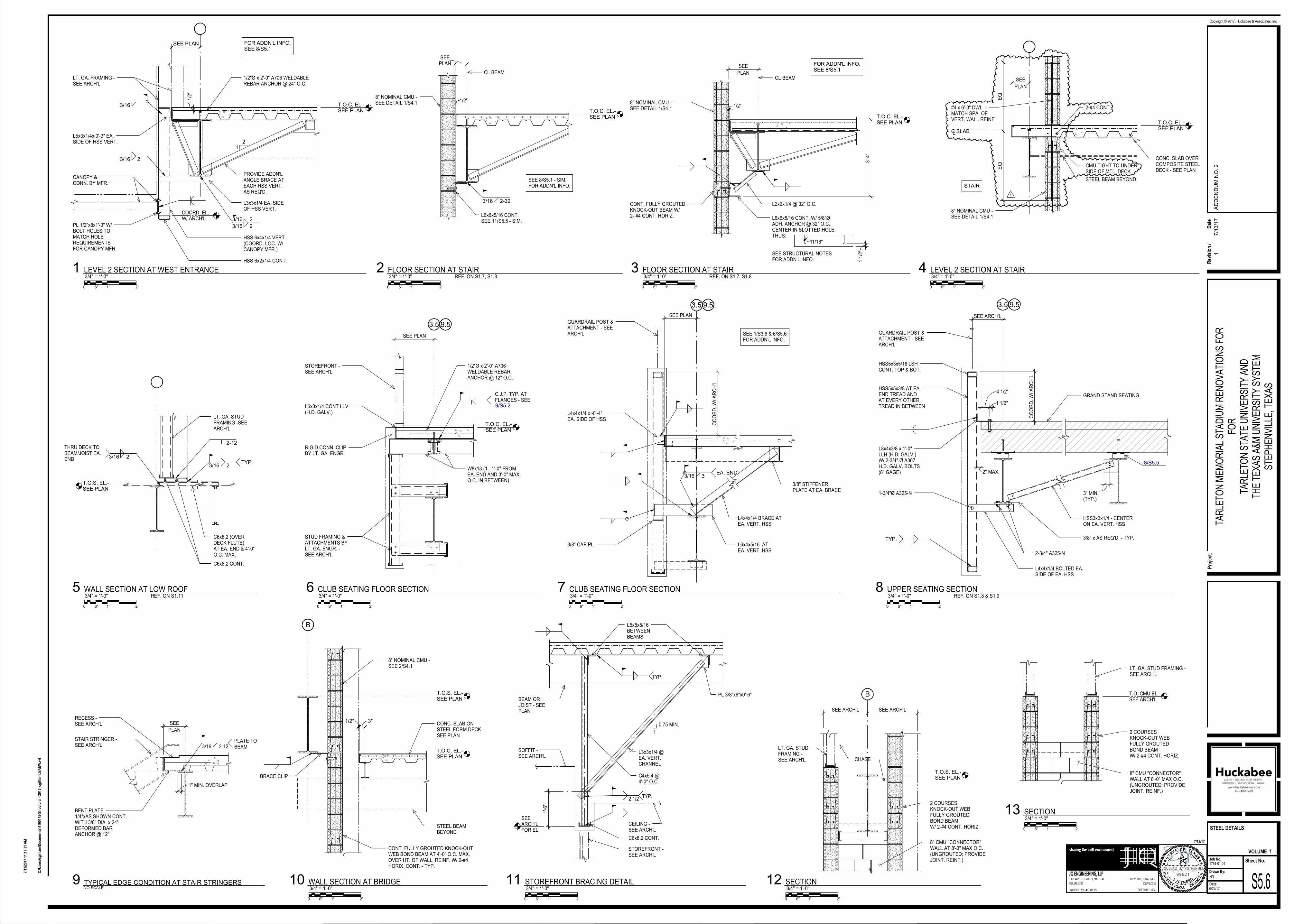
T.O.C. EL.-SEE PLAN T.O.C. EL.-
SEE PLAN T.O.C. EL.-SEE PLAN T.O.C. EL.-
SEE PLAN
T.O.S. EL.-SEE PLAN
T.O.S. EL.-SEE PLAN
T.O.C. EL.-SEE PLAN
T.O.C. EL.-SEE PLAN
T.O.S. EL.-SEE PLAN
LT. GA. FRAMING -SEE ARCH'L
1/2"Ø x 2'-0" A706 WELDABLEREBAR ANCHOR @ 24" O.C.
SEE PLAN
CANOPY &CONN. BY MFR.
COORD. EL.W/ ARCH'L
1 1
/2"
12
PROVIDE ADDN'LANGLE BRACE ATEACH HSS VERT.AS REQ'D.
L3x3x1/4 EA. SIDEOF HSS VERT.
HSS 6x4x1/4 VERT.(COORD. LOC. W/CANOPY MFR.)
HSS 6x2x1/4 CONT.
L5x3x1/4x 0'-3" EA.SIDE OF HSS VERT.
PL 1/2"x8x1'-0" W/BOLT HOLES TOMATCH HOLEREQUIREMENTSFOR CANOPY MFR.
3/16 2
3/16 2
3/16 2
3/16
FOR ADDN'L INFO.SEE 8/S5.1
1/2"
CL BEAM
PLANSEE
8" NOMINAL CMU -SEE DETAIL 1/S4.1
3/16 2-32
L6x6x5/16 CONT.SEE 11/S5.5 - SIM.
SEE 8/S5.1 - SIM.FOR ADDN'L INFO.
CL BEAMPLAN
SEE
8" NOMINAL CMU -SEE DETAIL 1/S4.1
L6x6x5/16 CONT. W/ 5/8"ØADH. ANCHOR @ 32" O.C.,CENTER IN SLOTTED HOLE.THUS:
SEE STRUCTURAL NOTESFOR ADDN'L INFO.
1/2"
3'-4
"
CONT. FULLY GROUTEDKNOCK-OUT BEAM W/2- #4 CONT. HORIZ.
1 1
/2"
11/16"
L2x2x1/4 @ 32" O.C.
FOR ADDN'L INFO.SEE 8/S5.1
8" NOMINAL CMU -SEE DETAIL 1/S4.1
STAIR
#4 x 6'-0" DWL. -MATCH SPA. OFVERT. WALL REINF.
STEEL BEAM BEYOND
2-#4 CONT.
CONC. SLAB OVERCOMPOSITE STEELDECK - SEE PLAN
PLAN
SEE
CL SLAB
EQ
EQ CMU TIGHT TO UNDER
SIDE OF MTL. DECK
1
3/16 2TYP.
2-12
LT. GA. STUDFRAMING -SEEARCH'L
C6x8.2 (OVERDECK FLUTE)AT EA. END & 4'-0"O.C. MAX.
C6x8.2 CONT.
3/16 2
THRU DECK TOBEAM/JOIST EA.END
SEE ARCH'L
3" MIN.(TYP.)
CO
OR
D.
W/
AR
CH
'L
GUARDRAIL POST &ATTACHMENT - SEEARCH'L
HSS5x5x3/8 AT EA.END TREAD ANDAT EVERY OTHERTREAD IN BETWEEN
HSS5x3x5/16 LSHCONT. TOP & BOT.
L8x4x3/8 x 1'-0"LLH (H.D. GALV.)W/ 2-3/4" Ø A307H.D. GALV. BOLTS(8" GAGE) 2" MAX.
4 1/2"
1 1/2"
HSS3x3x1/4 - CENTERON EA. VERT. HSS
3/8" x AS REQ'D. - TYP.
GRAND STAND SEATING
2-3/4" A325-N
L4x4x1/4 BOLTED EA.SIDE OF EA. HSS
1-3/4"Ø A325-N
TYP.
8/S5.5
3.5 9.5
BENT PLATE1/4"xAS SHOWN CONT.WITH 3/8" DIA. x 24"DEFORMED BARANCHOR @ 12"
STAIR STRINGER -SEE ARCH'L
RECESS -SEE ARCH'L
PLAN
SEE
3/16 2-12.
PLATE TOBEAM
1" MIN. OVERLAP
1/2" 3"CONC. SLAB ONSTEEL FORM DECK -SEE PLAN
STEEL BEAMBEYOND
CONT. FULLY GROUTED KNOCK-OUTWEB BOND BEAM AT 4'-0" O.C. MAX.OVER HT. OF WALL. REINF. W/ 2-#4HORIX. CONT. - TYP.
8" NOMINAL CMU -SEE 2/S4.1
B
BRACE CLIP
STOREFRONT -SEE ARCH'L
RIGID CONN. CLIPBY LT. GA. ENGR.
STUD FRAMING &ATTACHMENTS BYLT. GA. ENGR. -SEE ARCH'L
SEE PLAN
1/2"Ø x 2'-0" A706WELDABLE REBARANCHOR @ 12" O.C.
W8x13 (1 - 1'-0" FROMEA. END AND 3'-0" MAX.O.C. IN BETWEEN)
C.J.P. TYP. ATFLANGES - SEE
L6x3x1/4 CONT LLV(H.D. GALV.)
9/S5.2
3.5 9.5
L4x4x1/4 x -0'-4"EA. SIDE OF HSS
3/8" CAP PL.
GUARDRAIL POST &ATTACHMENT - SEEARCH'L
SEE PLAN
CO
OR
D.
W/
AR
CH
'L
3/8" STIFFENERPLATE AT EA. BRACE
L4x4x1/4 BRACE ATEA. VERT. HSS
L6x4x5/16 ATEA. VERT. HSS
3/16 3EA. END
3.5 9.5
SEE 1/S3.6 & 6/S5.6FOR ADDN'L INFO.
L5x5x5/16BETWEENBEAMS
BEAM ORJOIST - SEEPLAN
0.75 MIN.
1
PL 3/8"x6"x0'-6"
L3x3x1/4 @EA. VERT.CHANNEL
C6x8.2 CONT.
SEEARCH'LFOR EL.
1'-6
"
.
.
TYP.
2 1/2.
TYP.
.
C4x5.4 @4'-0" O.C.
STOREFRONT -SEE ARCH'L
SOFFIT -SEE ARCH'L
CEILING -SEE ARCH'L
2 COURSESKNOCK-OUT WEBFULLY GROUTEDBOND BEAMW/ 2-#4 CONT. HORIZ.
8" CMU "CONNECTOR"WALL AT 8'-0" MAX O.C.(UNGROUTED; PROVIDEJOINT. REINF.)
LT. GA. STUDFRAMING -SEE ARCH'L
SEE ARCH'L SEE ARCH'L
B
CHASE
2 COURSESKNOCK-OUT WEBFULLY GROUTEDBOND BEAMW/ 2-#4 CONT. HORIZ.
8" CMU "CONNECTOR"WALL AT 8'-0" MAX O.C.(UNGROUTED; PROVIDEJOINT. REINF.)
LT. GA. STUD FRAMING -SEE ARCH'L
T.O. CMU EL.-SEE ARCH'L
DOUGLAS J. ROTHERMEL
99821
1301 WEST 7TH STREET, SUITE 141
817.546.7200
FORT WORTH, TEXAS 76102
TBPE FIRM F-1294
JQ ENGINEERING, LLP
JQENG.COM
JQ PROJECT NO:
shaping the built environment
Sheet No.Job No.
Drawn By:
Date:
Pro
ject
:
Copyright © 2017, Huckabee & Associates, Inc.
VOLUME
4160175
7/13/17
C:\
Use
rs\c
gill
iam
\Do
cum
ents
\416
0175
-Str
uct
ura
l - 2
016_
cgill
iam
LB
AE
W.r
vt
7/13
/201
7 11
:17:
31 A
M
NR
S5.6
STEEL DETAILS
6/22/17
1754-01-01
TAR
LETO
N M
EM
OR
IAL
STA
DIU
M R
EN
OV
ATI
ON
S F
OR
FOR
TAR
LETO
N S
TATE
UN
IVE
RS
ITY
AN
DTH
E T
EX
AS
A&
M U
NIV
ER
SIT
Y S
YS
TEM
STE
PH
EN
VIL
LE, T
EX
AS
1
0 2'6" 1'
3/4" = 1'-0"LEVEL 2 SECTION AT WEST ENTRANCE1
0 2'6" 1'
3/4" = 1'-0"FLOOR SECTION AT STAIR2
REF. ON S1.7, S1.8
0 2'6" 1'
3/4" = 1'-0"FLOOR SECTION AT STAIR3
REF. ON S1.7, S1.8
0 2'6" 1'
3/4" = 1'-0"LEVEL 2 SECTION AT STAIR4
0 2'6" 1'
3/4" = 1'-0"WALL SECTION AT LOW ROOF5
REF. ON S1.11
0 2'6" 1'
3/4" = 1'-0"UPPER SEATING SECTION8
REF. ON S1.8 & S1.9
NO SCALE
9 TYPICAL EDGE CONDITION AT STAIR STRINGERS
0 2'6" 1'
3/4" = 1'-0"WALL SECTION AT BRIDGE10
0 2'6" 1'
3/4" = 1'-0"CLUB SEATING FLOOR SECTION6
0 2'6" 1'
3/4" = 1'-0"CLUB SEATING FLOOR SECTION7
0 2'6" 1'
3/4" = 1'-0"STOREFRONT BRACING DETAIL11
0 2'6" 1'
3/4" = 1'-0"SECTION12
0 2'6" 1'
3/4" = 1'-0"SECTION13
Rev
isio
n /
Dat
e
17/1
3/1
7A
DD
EN
DU
M N
O. 2
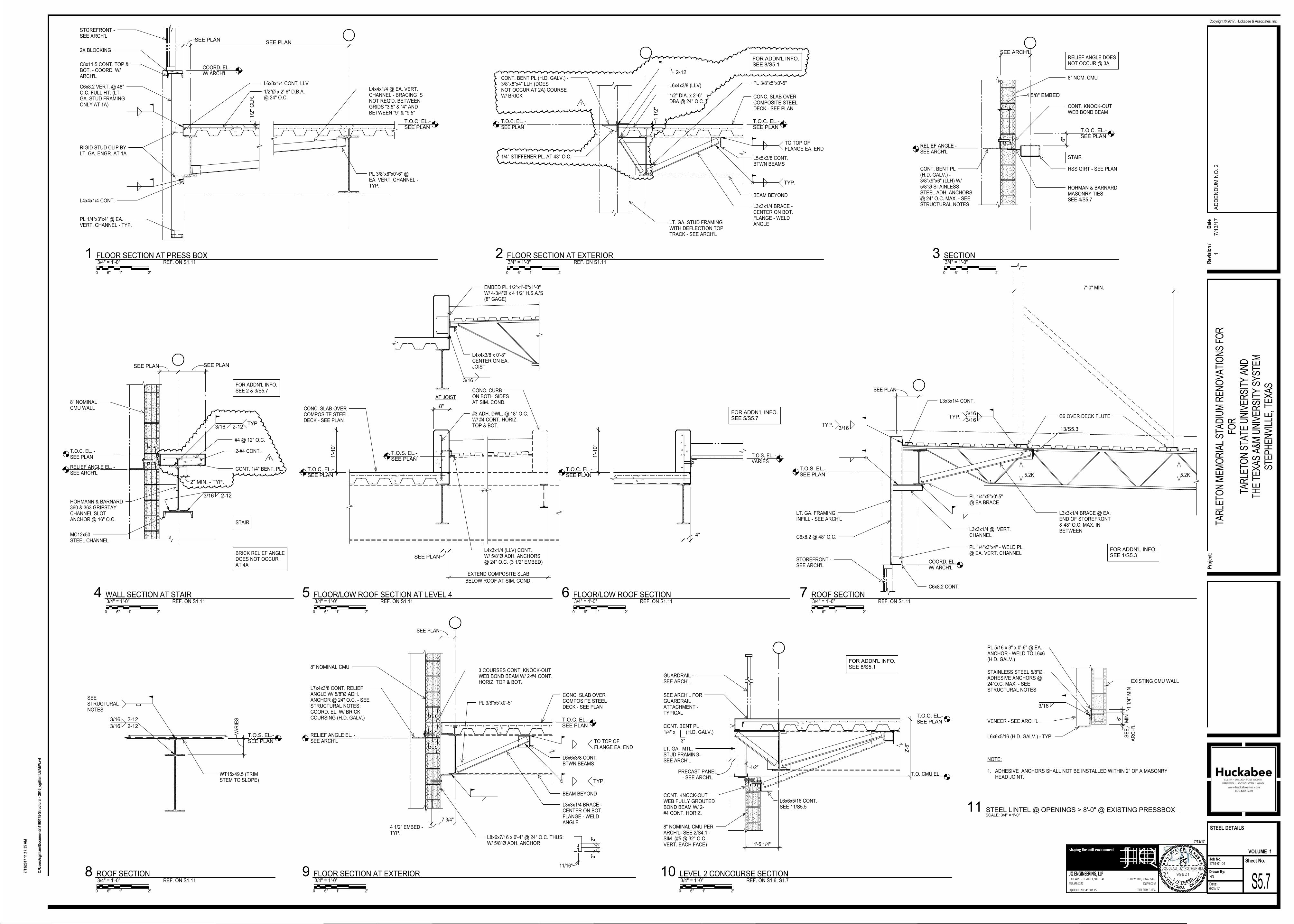
T.O.C. EL.-SEE PLAN
T.O.C. EL.-SEE PLAN
T.O.S. EL.-SEE PLAN
T.O.C. EL.-SEE PLAN
T.O.C. EL.-SEE PLAN
T.O.S. EL.-SEE PLAN
T.O.S. EL.-SEE PLAN
T.O.C. EL.-SEE PLAN
T.O.C. EL.-SEE PLAN
T.O.C. EL.-SEE PLAN
SEE PLANSEE PLAN
STOREFRONT -SEE ARCH'L
C6x8.2 VERT. @ 48"O.C. FULL HT. (LT.GA. STUD FRAMINGONLY AT 1A)
L4x4x1/4 @ EA. VERT.CHANNEL - BRACING ISNOT REQ'D. BETWEENGRIDS "3.5" & "4" ANDBETWEEN "9" & "9.5"
C8x11.5 CONT. TOP &BOT. - COORD. W/ARCH'L
PL 3/8"x6"x0'-6" @EA. VERT. CHANNEL -TYP.
COORD. EL.W/ ARCH'L
L6x3x1/4 CONT. LLV
L4x4x1/4 CONT.
PL 1/4"x3"x4" @ EA.VERT. CHANNEL - TYP.
1/2"Ø x 2'-6" D.B.A.@ 24" O.C.
1 1
/2"
CLR
.
RIGID STUD CLIP BYLT. GA. ENGR. AT 1A
2X BLOCKING
CONC. SLAB OVERCOMPOSITE STEELDECK - SEE PLAN
TO TOP OFFLANGE EA. END
L5x5x3/8 CONT.BTWN BEAMS
BEAM BEYOND
TYP.
L3x3x1/4 BRACE -CENTER ON BOT.FLANGE - WELDANGLE
PL 3/8"x5"x0'-5"CONT. BENT PL (H.D. GALV.) -3/8"x8"x4" LLH (DOESNOT OCCUR AT 2A) COURSEW/ BRICK
1/4" STIFFENER PL. AT 48" O.C.
L6x4x3/8 (LLV)
T.O.C. EL. -SEE PLAN
LT. GA. STUD FRAMINGWITH DEFLECTION TOPTRACK - SEE ARCH'L
1 1
/2"
1/2" DIA. x 2'-6"DBA @ 24" O.C.
2-12
FOR ADDN'L INFO.SEE 8/S5.1
1
#4 @ 12" O.C.
STAIR
RELIEF ANGLE EL. -SEE ARCH'L
T.O.C. EL. -SEE PLAN
SEE PLAN SEE PLAN
BRICK RELIEF ANGLEDOES NOT OCCURAT 4A
MC12x50STEEL CHANNEL
HOHMANN & BARNARD360 & 363 GRIPSTAYCHANNEL SLOTANCHOR @ 16" O.C.
3/16 2-12
8" NOMINALCMU WALL
FOR ADDN'L INFO.SEE 2 & 3/S5.7
2" MIN. - TYP.
CONT. 1/4" BENT. PL.
2-#4 CONT.
3/16 2-12TYP.
1 1'-10"
8"
#3 ADH. DWL. @ 18" O.C.W/ #4 CONT. HORIZ.TOP & BOT.
L4x3x1/4 (LLV) CONT.W/ 5/8"Ø ADH. ANCHORS@ 24" O.C. (3 1/2" EMBED)
SEE PLAN
CONC. SLAB OVERCOMPOSITE STEELDECK - SEE PLAN
AT JOIST
EMBED PL 1/2"x1'-0"x1'-0"W/ 4-3/4"Ø x 4 1/2" H.S.A.'S(8" GAGE)
L4x4x3/8 x 0'-8"CENTER ON EA.JOIST
CONC. CURBON BOTH SIDESAT SIM. COND.
BELOW ROOF AT SIM. COND.
EXTEND COMPOSITE SLAB
3/16
1'-10"
4"
T.O.S. EL. -VARIES
FOR ADDN'L INFO.SEE 5/S5.7
SEE PLAN
LT. GA. FRAMINGINFILL - SEE ARCH'L
STOREFRONT -SEE ARCH'L
13/S5.3
PL 1/4"x5"x0'-5"@ EA BRACE
L3x3x1/4 BRACE @ EA.END OF STOREFRONT& 48" O.C. MAX. INBETWEEN
FOR ADDN'L INFO.SEE 1/S5.3
7'-0" MIN.
5.2K5.2K
C6 OVER DECK FLUTETYP.3/16
3/16
L3x3x1/4 CONT.
L3x3x1/4 @ VERT.CHANNEL
COORD. EL.W/ ARCH'L
TYP.3/16
PL 1/4"x3"x4" - WELD PL@ EA. VERT. CHANNEL
C6x8.2 CONT.
C6x8.2 @ 48" O.C.
3/16 2-12
3/16 2-12
WT15x49.5 (TRIMSTEM TO SLOPE)
VA
RIE
S
SEESTRUCTURALNOTES
CONC. SLAB OVERCOMPOSITE STEELDECK - SEE PLAN
TO TOP OFFLANGE EA. END
L6x6x3/8 CONT.BTWN BEAMS
BEAM BEYOND
TYP.
L3x3x1/4 BRACE -CENTER ON BOT.FLANGE - WELDANGLE
SEE PLAN
PL 3/8"x5"x0'-5"
L7x4x3/8 CONT. RELIEFANGLE W/ 5/8"Ø ADH.ANCHOR @ 24" O.C. - SEESTRUCTURAL NOTES;COORD. EL. W/ BRICKCOURSING (H.D. GALV.)
8" NOMINAL CMU3 COURSES CONT. KNOCK-OUTWEB BOND BEAM W/ 2-#4 CONT.HORIZ. TOP & BOT.
RELIEF ANGLE EL. -SEE ARCH'L
L8x6x7/16 x 0'-4" @ 24" O.C. THUS:W/ 5/8"Ø ADH. ANCHOR
7 3/4"
4 1/2" EMBED -TYP.
11/16"
2"
2"
GUARDRAIL -SEE ARCH'L
CONT. BENT PL1/4" x (H.D. GALV.)
8" NOMINAL CMU PERARCH'L- SEE 2/S4.1 -SIM. (#5 @ 32" O.C.VERT. EACH FACE)
2'-6
"
T.O. CMU EL.
SEE ARCH'L FORGUARDRAILATTACHMENT -TYPICAL
3"
CONT. KNOCK-OUTWEB FULLY GROUTEDBOND BEAM W/ 2-#4 CONT. HORIZ.
L6x6x5/16 CONT.SEE 11/S5.5
- SEE ARCH'LPRECAST PANEL
LT. GA. MTL.STUD FRAMING-SEE ARCH'L
FOR ADDN'L INFO.SEE 8/S5.1
1'-5 1/4"
1/2"
3/S5.7
2/S5.74/S5.7
1/S5.7
PL 5/16 x 3" x 0'-6" @ EA.ANCHOR - WELD TO L6x6(H.D. GALV.)
EXISTING CMU WALL
STAINLESS STEEL 5/8"ØADHESIVE ANCHORS @24"O.C. MAX. - SEESTRUCTURAL NOTES
AR
CH
' L
SE
EM
IN6"
1 1
/4"
MIN
3/16
L6x6x5/16 (H.D. GALV.) - TYP.
VENEER - SEE ARCH'L
NOTE:
1. ADHESIVE ANCHORS SHALL NOT BE INSTALLED WITHIN 2" OF A MASONRYHEAD JOINT.
SEE ARCH'L
RELIEF ANGLE -SEE ARCH'L
6"
CONT. BENT PL(H.D. GALV.) -3/8"x9"x6" (LLH) W/5/8"Ø STAINLESSSTEEL ADH. ANCHORS@ 24" O.C. MAX. - SEESTRUCTURAL NOTES
HSS GIRT - SEE PLAN
HOHMAN & BARNARDMASONRY TIES -SEE 4/S5.7
CONT. KNOCK-OUTWEB BOND BEAM
STAIR
4 5/8" EMBED
8" NOM. CMU
RELIEF ANGLE DOESNOT OCCUR @ 3A
DOUGLAS J. ROTHERMEL
99821
1301 WEST 7TH STREET, SUITE 141
817.546.7200
FORT WORTH, TEXAS 76102
TBPE FIRM F-1294
JQ ENGINEERING, LLP
JQENG.COM
JQ PROJECT NO:
shaping the built environment
Sheet No.Job No.
Drawn By:
Date:
Pro
ject
:
Copyright © 2017, Huckabee & Associates, Inc.
VOLUME
4160175
7/13/17
C:\
Use
rs\c
gill
iam
\Do
cum
ents
\416
0175
-Str
uct
ura
l - 2
016_
cgill
iam
LB
AE
W.r
vt
7/13
/201
7 11
:17:
35 A
M
NR
S5.7
STEEL DETAILS
6/22/17
1754-01-01
TAR
LETO
N M
EM
OR
IAL
STA
DIU
M R
EN
OV
ATI
ON
S F
OR
FOR
TAR
LETO
N S
TATE
UN
IVE
RS
ITY
AN
DTH
E T
EX
AS
A&
M U
NIV
ER
SIT
Y S
YS
TEM
STE
PH
EN
VIL
LE, T
EX
AS
1
0 2'6" 1'
3/4" = 1'-0"FLOOR SECTION AT PRESS BOX1
REF. ON S1.11
0 2'6" 1'
3/4" = 1'-0"FLOOR SECTION AT EXTERIOR2
REF. ON S1.11
0 2'6" 1'
3/4" = 1'-0"WALL SECTION AT STAIR4
REF. ON S1.11
0 2'6" 1'
3/4" = 1'-0"FLOOR/LOW ROOF SECTION AT LEVEL 45
REF. ON S1.11
0 2'6" 1'
3/4" = 1'-0"FLOOR/LOW ROOF SECTION6
REF. ON S1.11
0 2'6" 1'
3/4" = 1'-0"ROOF SECTION7
REF. ON S1.11
0 2'6" 1'
3/4" = 1'-0"ROOF SECTION8
REF. ON S1.11
0 2'6" 1'
3/4" = 1'-0"FLOOR SECTION AT EXTERIOR9
0 2'6" 1'
3/4" = 1'-0"LEVEL 2 CONCOURSE SECTION10
REF. ON S1.6, S1.7
SCALE: 3/4" = 1'-0"
11 STEEL LINTEL @ OPENINGS > 8'-0" @ EXISTING PRESSBOX
0 2'6" 1'
3/4" = 1'-0"SECTION3
Rev
isio
n /
Dat
e
17/1
3/1
7A
DD
EN
DU
M N
O. 2
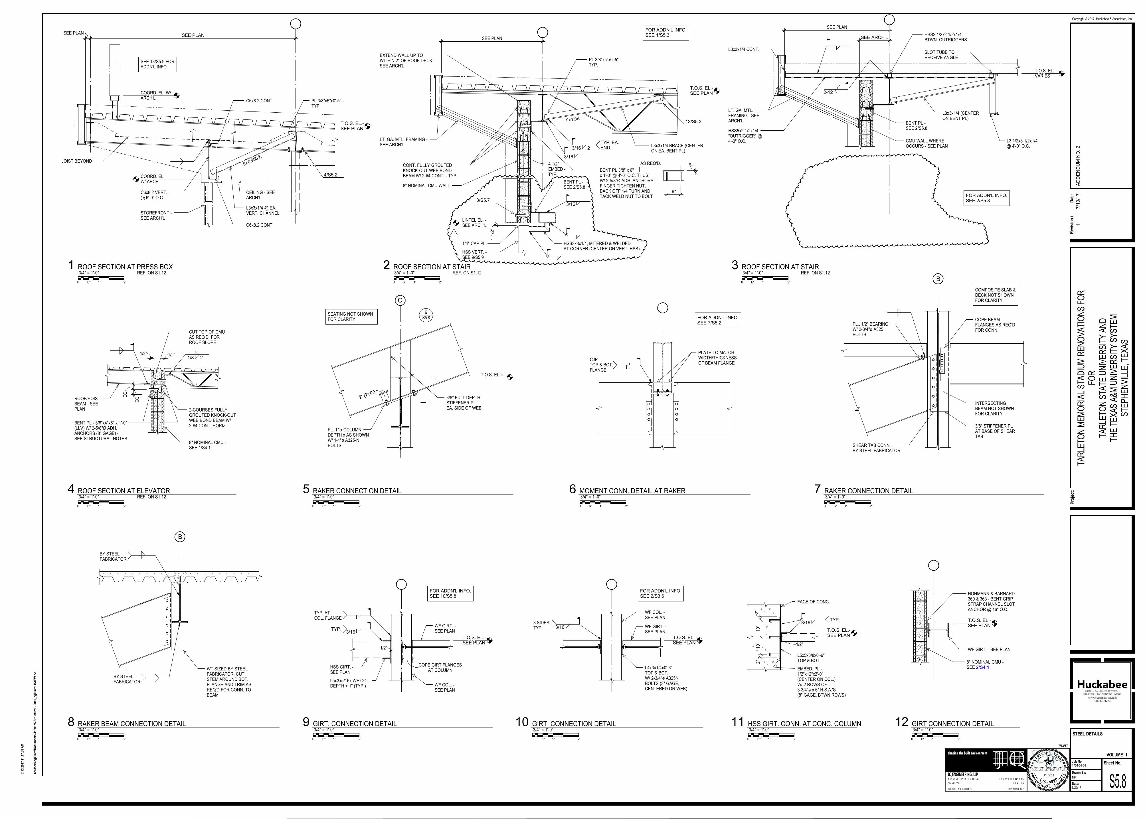
T.O.S. EL.-SEE PLAN
T.O.S. EL.-SEE PLAN
T.O.S. EL.-SEE PLAN
T.O.S. EL.-SEE PLAN
T.O.S. EL.-SEE PLAN
T.O.S. EL.-SEE PLAN
SEE PLANSEE PLAN
C6x8.2 VERT.@ 6'-0" O.C.
STOREFRONT -SEE ARCH'L
COORD. EL.W/ ARCH'L
L3x3x1/4 @ EA.VERT. CHANNEL
CEILING - SEEARCH'L
C6x8.2 CONT.
PL 3/8"x5"x0'-5" -TYP.
4/S5.2
R=0.950 K
COORD. EL. W/ARCH'L
JOIST BEYOND
C6x8.2 CONT.
SEE 13/S5.9 FORADDN'L INFO.
SEE PLAN
EXTEND WALL UP TOWITHIN 2" OF ROOF DECK -SEE ARCH'L
FOR ADDN'L INFO.SEE 1/S5.3
CONT. FULLY GROUTEDKNOCK-OUT WEB BONDBEAM W/ 2-#4 CONT. - TYP.
LT. GA. MTL. FRAMING -SEE ARCH'L
4 1/2"EMBED -TYP.
8" NOMINAL CMU WALL
BENT PL 3/8" x 6"x 1'-0" @ 4'-0" O.C. THUS:W/ 2-5/8"Ø ADH. ANCHORSFINGER TIGHTEN NUT,BACK OFF 1/4 TURN ANDTACK WELD NUT TO BOLT
AS REQ'D.
8"
1"
3/16
13/S5.3
PL 3/8"x5"x0'-5" -TYP.
3/16 2
TYP. EA.END
F=1.0K
L3x3x1/4 BRACE (CENTERON EA. BENT PL)
BENT PL -SEE 2/S5.8
HSS3x3x1/4, MITERED & WELDEDAT CORNER (CENTER ON VERT. HSS)
1/4" CAP PL
HSS VERT. -SEE 9/S5.9
LINTEL EL. -SEE ARCH'L
3/S5.7
1 1
/2"
3/16
1
SEE PLAN
LT. GA. MTL.FRAMING - SEEARCH'L
L3x3x1/4 CONT.
HSS5x2 1/2x1/4"OUTRIGGER" @4'-0" O.C.
SLOT TUBE TORECEIVE ANGLE
HSS2 1/2x2 1/2x1/4BTWN. OUTRIGGERS
2-12
L3 1/2x3 1/2x1/4@ 4'-0" O.C.
T.O.S. EL. -VARIES
CMU WALL WHEREOCCURS - SEE PLAN
SEE ARCH'L
BENT PL -SEE 2/S5.8
FOR ADDN'L INFO.SEE 2/S5.8
L3x3x1/4 (CENTERON BENT PL)
EQ
EQ
1/2"
ROOF/HOISTBEAM - SEEPLAN
BENT PL - 3/8"x4"x6" x 1'-0"(LLV) W/ 2-5/8"Ø ADH.ANCHORS (8" GAGE) -SEE STRUCTURAL NOTES
CUT TOP OF CMUAS REQ'D. FORROOF SLOPE
1/8 21/2"
2-COURSES FULLYGROUTED KNOCK-OUTWEB BOND BEAM W/2-#4 CONT. HORIZ.
8" NOMINAL CMU -SEE 1/S4.1
PLATE TO MATCHWIDTH/THICKNESSOF BEAM FLANGE
CJPTOP & BOT.FLANGE
FOR ADDN'L INFO.SEE 7/S5.2
1/2"
WF COL. -SEE PLAN
AT COLUMNCOPE GIRT FLANGES
TYP.3/16
TYP. ATCOL. FLANGE
HSS GIRT. -SEE PLAN
L5x3x5/16x WF COL.DEPTH + 1" (TYP.)
WF GIRT. -SEE PLAN
FOR ADDN'L INFO.SEE 10/S5.8
WF COL. -SEE PLAN
3/163 SIDES -TYP. WF GIRT. -
SEE PLAN
FOR ADDN'L INFO.SEE 2/S3.6
L4x3x1/4x0'-6"TOP & BOT.W/ 2-3/4"ø A325NBOLTS (3" GAGE,CENTERED ON WEB)
1/2"
L5x5x3/8x0'-6"TOP & BOT.
EMBED. PL -1/2"x12"x2'-0"(CENTER ON COL.)W/ 2 ROWS OF3-3/4"ø x 6" H.S.A.'S(8" GAGE, BTWN ROWS)
3/16TYP.
FACE OF CONC.
2"
10"
10"
2"
HOHMANN & BARNARD360 & 363 - BENT GRIPSTRAP CHANNEL SLOTANCHOR @ 16" O.C.
WF GIRT. - SEE PLAN
8" NOMINAL CMU -SEE 2/S4.1
B
PL., 1/2" BEARINGW/ 2-3/4"ø A325BOLTS
COPE BEAMFLANGES AS REQ'DFOR CONN.
COMPOSITE SLAB &DECK NOT SHOWNFOR CLARITY
INTERSECTINGBEAM NOT SHOWNFOR CLARITY
SHEAR TAB CONN.BY STEEL FABRICATOR
3/8" STIFFENER PLAT BASE OF SHEARTAB
C
PL. 1" x COLUMNDEPTH x AS SHOWNW/ 1-1"ø A325-NBOLTS
T.O.S. EL.=
SEATING NOT SHOWNFOR CLARITY
3/8" FULL DEPTHSTIFFENER PL.EA. SIDE OF WEB
2" (TYP.)
2" (TYP.)
6S5.8
B
BY STEELFABRICATOR
WT SIZED BY STEELFABRICATOR. CUTSTEM AROUND BOT.FLANGE AND TRIM ASREQ'D FOR CONN. TOBEAM
BY STEELFABRICATOR
DOUGLAS J. ROTHERMEL
99821
1301 WEST 7TH STREET, SUITE 141
817.546.7200
FORT WORTH, TEXAS 76102
TBPE FIRM F-1294
JQ ENGINEERING, LLP
JQENG.COM
JQ PROJECT NO:
shaping the built environment
Sheet No.Job No.
Drawn By:
Date:
Pro
ject
:
Copyright © 2017, Huckabee & Associates, Inc.
VOLUME
4160175
7/13/17
C:\
Use
rs\c
gill
iam
\Do
cum
ents
\416
0175
-Str
uct
ura
l - 2
016_
cgill
iam
LB
AE
W.r
vt
7/13
/201
7 11
:17:
38 A
M
NR
S5.8
STEEL DETAILS
6/22/17
1754-01-01
TAR
LETO
N M
EM
OR
IAL
STA
DIU
M R
EN
OV
ATI
ON
S F
OR
FOR
TAR
LETO
N S
TATE
UN
IVE
RS
ITY
AN
DTH
E T
EX
AS
A&
M U
NIV
ER
SIT
Y S
YS
TEM
STE
PH
EN
VIL
LE, T
EX
AS
1
0 2'6" 1'
3/4" = 1'-0"ROOF SECTION AT PRESS BOX1
REF. ON S1.12
0 2'6" 1'
3/4" = 1'-0"ROOF SECTION AT STAIR2
REF. ON S1.12
0 2'6" 1'
3/4" = 1'-0"ROOF SECTION AT STAIR3
REF. ON S1.12
0 2'6" 1'
3/4" = 1'-0"ROOF SECTION AT ELEVATOR4
REF. ON S1.12
0 2'6" 1'
3/4" = 1'-0"MOMENT CONN. DETAIL AT RAKER6
0 2'6" 1'
3/4" = 1'-0"GIRT. CONNECTION DETAIL9
0 2'6" 1'
3/4" = 1'-0"GIRT. CONNECTION DETAIL10
0 2'6" 1'
3/4" = 1'-0"HSS GIRT. CONN. AT CONC. COLUMN11
0 2'6" 1'
3/4" = 1'-0"GIRT CONNECTION DETAIL12
0 2'6" 1'
3/4" = 1'-0"RAKER CONNECTION DETAIL7
0 2'6" 1'
3/4" = 1'-0"RAKER CONNECTION DETAIL5
0 2'6" 1'
3/4" = 1'-0"RAKER BEAM CONNECTION DETAIL8
Rev
isio
n /
Dat
e
17/1
3/1
7A
DD
EN
DU
M N
O. 2

Project Name: Tarleton Memorial Stadium Renovations
Client: Tarleton State University and the Texas A&M University System
Stephenville, Texas
Project Number: 1754-01-01
Structural Items For
Addendum No. 2
Page 2 of 2
AD No 2 Struct. Item 9: To the Drawings, Sheet S1.10
Clarified detailing along grid 3.5 and 9.5.
AD No 2 Struct. Item 10: To the Drawings, Sheet S1.11
Deleted plan note 13.
AD No 2 Struct. Item 11: To the Drawings, Sheet S1.11
Revised beam sizes and beam reactions.
AD No 2 Struct. Item 12: To the Drawings, Sheet S1.11
Clarified detailing along grid 3.5 and 9.5.
AD No 2 Struct. Item 13: To the Drawings, Sheet S1.12
Revised beam reactions.
AD No 2 Struct. Item 14: To the Drawings, Sheet S3.3
Added detail 4.
AD No 2 Struct. Item 15: To the Drawings, Sheet S5.1
Added detail 14.
AD No 2 Struct. Item 16: To the Drawings, Sheet S5.6
Revised detail 4.
AD No 2 Struct. Item 17: To the Drawings, Sheet S5.7
Revised detail 2.
AD No 2 Struct. Item 18: To the Drawings, Sheet S5.7
Revised detail 4.
END OF STRUCTURAL ADDENDUM
FIRM NO. 1294
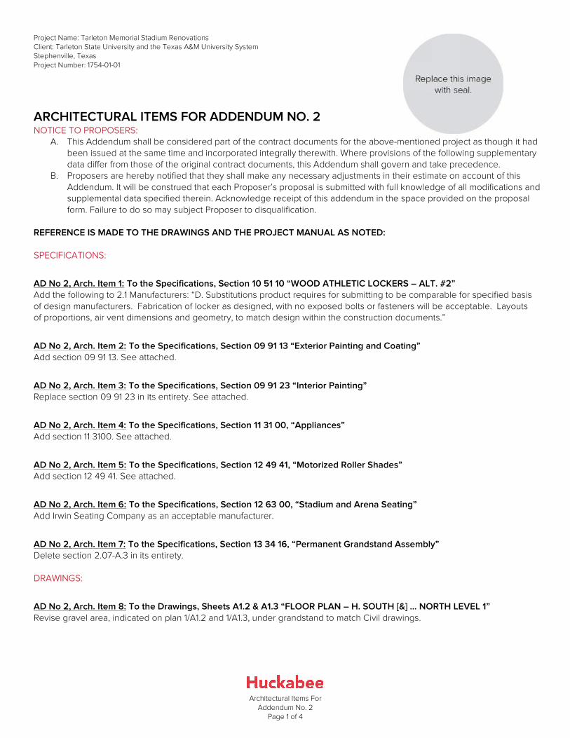
Project Name: Tarleton Memorial Stadium Renovations
Client: Tarleton State University and the Texas A&M University System
Stephenville, Texas
Project Number: 1754-01-01
Architectural Items For
Addendum No. 2
Page 1 of 4
ARCHITECTURAL ITEMS FOR ADDENDUM NO. 2 NOTICE TO PROPOSERS:
A. This Addendum shall be considered part of the contract documents for the above-mentioned project as though it had
been issued at the same time and incorporated integrally therewith. Where provisions of the following supplementary
data differ from those of the original contract documents, this Addendum shall govern and take precedence.
B. Proposers are hereby notified that they shall make any necessary adjustments in their estimate on account of this
Addendum. It will be construed that each Proposer’s proposal is submitted with full knowledge of all modifications and
supplemental data specified therein. Acknowledge receipt of this addendum in the space provided on the proposal
form. Failure to do so may subject Proposer to disqualification.
REFERENCE IS MADE TO THE DRAWINGS AND THE PROJECT MANUAL AS NOTED:
SPECIFICATIONS:
AD No 2, Arch. Item 1: To the Specifications, Section 10 51 10 “WOOD ATHLETIC LOCKERS – ALT. #2”
Add the following to 2.1 Manufacturers: “D. Substitutions product requires for submitting to be comparable for specified basis
of design manufacturers. Fabrication of locker as designed, with no exposed bolts or fasteners will be acceptable. Layouts
of proportions, air vent dimensions and geometry, to match design within the construction documents.”
AD No 2, Arch. Item 2: To the Specifications, Section 09 91 13 “Exterior Painting and Coating”
Add section 09 91 13. See attached.
AD No 2, Arch. Item 3: To the Specifications, Section 09 91 23 “Interior Painting”
Replace section 09 91 23 in its entirety. See attached.
AD No 2, Arch. Item 4: To the Specifications, Section 11 31 00, “Appliances”
Add section 11 3100. See attached.
AD No 2, Arch. Item 5: To the Specifications, Section 12 49 41, “Motorized Roller Shades”
Add section 12 49 41. See attached.
AD No 2, Arch. Item 6: To the Specifications, Section 12 63 00, “Stadium and Arena Seating”
Add Irwin Seating Company as an acceptable manufacturer.
AD No 2, Arch. Item 7: To the Specifications, Section 13 34 16, “Permanent Grandstand Assembly”
Delete section 2.07-A.3 in its entirety.
DRAWINGS:
AD No 2, Arch. Item 8: To the Drawings, Sheets A1.2 & A1.3 “FLOOR PLAN – H. SOUTH [&] … NORTH LEVEL 1”
Revise gravel area, indicated on plan 1/A1.2 and 1/A1.3, under grandstand to match Civil drawings.
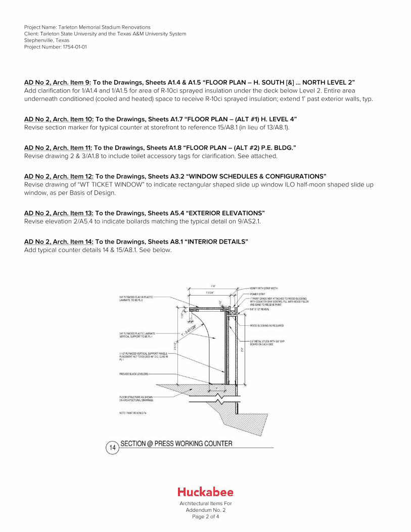
Project Name: Tarleton Memorial Stadium Renovations
Client: Tarleton State University and the Texas A&M University System
Stephenville, Texas
Project Number: 1754-01-01
Architectural Items For
Addendum No. 2
Page 2 of 4
AD No 2, Arch. Item 9: To the Drawings, Sheets A1.4 & A1.5 “FLOOR PLAN – H. SOUTH [&] … NORTH LEVEL 2”
Add clarification for 1/A1.4 and 1/A1.5 for area of R-10ci sprayed insulation under the deck below Level 2. Entire area
underneath conditioned (cooled and heated) space to receive R-10ci sprayed insulation; extend 1’ past exterior walls, typ.
AD No 2, Arch. Item 10: To the Drawings, Sheets A1.7 “FLOOR PLAN – (ALT #1) H. LEVEL 4”
Revise section marker for typical counter at storefront to reference 15/A8.1 (in lieu of 13/A8.1).
AD No 2, Arch. Item 11: To the Drawings, Sheets A1.8 “FLOOR PLAN – (ALT #2) P.E. BLDG.”
Revise drawing 2 & 3/A1.8 to include toilet accessory tags for clarification. See attached.
AD No 2, Arch. Item 12: To the Drawings, Sheets A3.2 “WINDOW SCHEDULES & CONFIGURATIONS”
Revise drawing of “WT TICKET WINDOW” to indicate rectangular shaped slide up window ILO half-moon shaped slide up
window, as per Basis of Design.
AD No 2, Arch. Item 13: To the Drawings, Sheets A5.4 “EXTERIOR ELEVATIONS”
Revise elevation 2/A5.4 to indicate bollards matching the typical detail on 9/AS2.1.
AD No 2, Arch. Item 14: To the Drawings, Sheets A8.1 “INTERIOR DETAILS”
Add typical counter details 14 & 15/A8.1. See below.

Project Name: Tarleton Memorial Stadium Renovations
Client: Tarleton State University and the Texas A&M University System
Stephenville, Texas
Project Number: 1754-01-01
Architectural Items For
Addendum No. 2
Page 3 of 4
AD No 2, Arch. Item 15: To the Drawings, Sheets A9.5 “GRAPHICS AND WAYFINDING PLAN - H. LEVEL 1 (W/ ALT.#3)
Clarification: The intent with the signs shown in legend 3/A9.5 is for the graphics to be white, not laser/water jet cut into the
background.
AD No 2, Arch. Item 16: To the Drawings, Sheets A9.9 “GRAPHICS AND WAYFINDING H. ELEVATIONS & DETAILS”
Add detail 13/A9.9 for West Façade graphic. Revise Graphic at enlarged elevation 4/A9.9 at West Façade to include Tarleton
T w/Texas shape. See below.
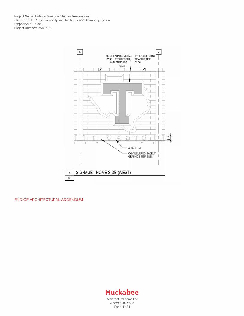
Project Name: Tarleton Memorial Stadium Renovations
Client: Tarleton State University and the Texas A&M University System
Stephenville, Texas
Project Number: 1754-01-01
Architectural Items For
Addendum No. 2
Page 4 of 4
END OF ARCHITECTURAL ADDENDUM
Project No. 04-3176, Memorial Stadium Renovation and ExpansionTarleton State University - Stephenville, Texas
Huckabee 09 9113 - 1
A/E Project No. 1754-01-01 EXTERIOR PAINTING AND COATING
SECTION 09 9113
EXTERIOR PAINTING AND COATING
PART 1 - GENERAL
1.01 SUMMARY
A. Related Documents: General and Supplementary Conditions of the Contract, Division 01 General Requirements, and Drawings are applicable to this Section.
B. Section Includes, but is not limited to:
1. Exterior paints and coatings systems including; paints, stains, transparent coatings, and opaque finishes.
2. For interior paints and coating refer to Section 09 9123-Interior Painting.
3. Specific products and painting scheduled in this Section are based, in general, on products of Sherwin-Williams Company (noted SW). Products of other manufacturers listed in paragraph 2.01 may be substituted with approved color matches.
C. Related Sections
1. Section 05 2100 - Steel Joist Framing: Shop priming
2. Section 05 5000 - Metal Fabrications: Shop priming
3. Section 06 2000 - Finish Carpentry: Back priming of trim and paneling
4. Division 23 - Mechanical Identification: Markers and color-coding
5. Division 26 - Electrical Identification: Markers and color-coding
1.02 REFERENCES
A. Industry Association Standards
1. SSPC-SP 1 - Solvent Cleaning.
2. SSPC-SP 2 - Hand Tool Cleaning.
3. SSPC-SP 3 - Power Tool Cleaning.
4. SSPC-SP 13 / NACE No. 6 Surface Preparation for Concrete.
1.03 DEFINITIONS
A. Paint
1. Means coating systems materials including primers, emulsions, epoxy, enamels, sealers, fillers, and other applied materials whether used as prime, intermediate, or finish coats.
1.04 SUBMITTALS
A. Shop drawings, product data, and samples under provisions of Section 01 3000 - Administrative Requirements.
B. Product Data: Manufacturer's data sheets on each paint and coating product should include:
1. Product characteristics
2. Surface preparation instructions and recommendations
3. Primer requirements and finish specification
4. Storage and handling requirements and recommendations
5. Application methods
6. Cautions
C. Selection Samples: Submit a complete set of color chips that represent the full range of manufacturer's color samples available.
D. Verification Samples: For each finish product specified, submit 8”x10” samples that represent actual product, color, and sheen.
E. Closeout Submittals
1. Submit under provisions of Section 01 7800 - Closeout Submittals.
2. Upon conclusion of the project, the Contractor or paint manufacture/supplier shall furnish a coating maintenance manual, such as Sherwin-Williams “Custodian Project Color and Product Information” report or equal. Manual shall include an Area Summary with finish schedule, Area Detail designating where each product/color/finish was used, product data
Project No. 04-3176, Memorial Stadium Renovation and ExpansionTarleton State University - Stephenville, Texas
Huckabee 09 9113 - 2
A/E Project No. 1754-01-01 EXTERIOR PAINTING AND COATING
pages, Material Safety Data Sheets, care and cleaning instructions, touchup procedures, and color samples of each color and finish used.
1.05 QUALITY ASSURANCE
A. Qualifications
1. Single Source Responsibility:
a. Obtain each type of material required from single source.
B. Pre-installation Meetings
1. Comply with provisions of Section 01 3000 - Administrative Requirements.
1.06 DELIVERY, STORAGE, AND HANDLING
A. Comply with requirements of Section 01 6000 - Product Requirements.
B. Delivery: Deliver manufacturer's unopened containers to the work site. Packaging shall bear the manufacturer's name, label, and the following list of information:
1. Product name, type (description)
2. Application and use instructions
3. Surface preparation
4. VOC content
5. Environmental issues
6. Batch date
7. Color number
C. Storage: Store and dispose of solvent-based materials, and materials used with solvent-based materials, in accordance with requirements of local authorities having jurisdiction.
D. Store materials in an area that is within the acceptable temperature range, per manufacturers instructions. Protect from freezing.
E. Handling: Maintain a clean, dry storage area, to prevent contamination or damage to the coatings.
1.07 PROJECT CONDITIONS
A. Project Environmental Requirements
1. Maintain environmental conditions (temperature, humidity, and ventilation) within limits recommended by manufacturer for optimum results. Do not apply coatings under environmental conditions outside manufacturer's absolute limits.
1.08 MAINTENANCE
A. Extra Materials
1. At completion of project, deliver to Owner extra stock of materials used on project as follows:
a. Five (5) gallons for each field color/type, three (3) gallons for trim and accent of each color/type.
2. Store in location as directed by Owner.
3. Ensure containers are sealed and identified by manufacturer, type, and color.
4. Submit maintenance data under provisions of Section 01 7800 - Closeout Submittals.
5. Include cleaning methods, and recommended cleaning solutions.
PART 2 - PRODUCTS
2.01 MANUFACTURERS
A. Subject to compliance with requirements indicated herein, provide products of one of the listed manufacturers.
B. Sherwin-Williams Co.: www.sherwin-williams.com.
C. Coronado Industrial Coatings: www.coronadopaint.com.
D. PPG Paints: www.ppgpaints.com
E. Benjamin Moore & Co.: www.benjaminmoore.com.
Project No. 04-3176, Memorial Stadium Renovation and ExpansionTarleton State University - Stephenville, Texas
Huckabee 09 9113 - 3
A/E Project No. 1754-01-01 EXTERIOR PAINTING AND COATING
F. Substitutions: Under provisions of Section 01 6000 - Product Requirements.
2.02 MATERIALS - GENERAL
A. Paints and Coatings - General
1. Unless otherwise indicated, provide factory-mixed coatings. When required, mix coatings to correct consistency in accordance with manufacturer's instructions before application. Do not reduce, thin, or dilute coatings or add materials to coatings unless such procedure is specifically described in manufacturer's product instructions.
2. For opaque finishes, tint each coat including primer coat and intermediate coats, one-half shade lighter than succeeding coat, with final finish coat as base color.
B. Primers
1. Where the manufacturer offers options on primers for a particular substrate, use primer categorized as "best" by the manufacturer.
2.03 COLOR SCHEDULES
A. Color schedule in Section 01 6210 - Schedule of Materials and Colors.
B. The Architect may select, allocate, and vary colors on different surfaces throughout the Work, subject to the following.
1. Exterior work: A maximum of three (3) different colors will be used, with variations for trim, doors, miscellaneous work, and metal work.
C. All painted graphics shown on the drawings shall be included in the base proposal and shall be included in this section. Contractor shall note that school colors and mascot may be released after initial color selection. Contractor shall make all necessary adjustments.
2.04 MISCELLANEOUS MATERIALS
A. Coating Application Accessories
1. Provide all primers, sealers, cleaning agents, cleaning cloths, sanding materials, and clean-up materials required per manufacturer's specifications.
2.05 INTERIOR DRYWALL TEXTURING
A. Interior drywall texturing compounds shall be equal to U.S.G. “Multi-Purpose Texture Finish”, or U.S.G. “Texture XII Drywall Surfacer”. Unless shown or otherwise indicated on the drawings, provide medium “Orange Peel or Spatter Finish” texture on walls or ceilings, as directed by Architect.
B. Mix 1 Gallon of latex paint with each 50 lbs. of texture.
PART 3 - EXECUTION
3.01 EXAMINATION
A. Do not begin application of coatings until substrates have been properly prepared. Notify Architect of unsatisfactory conditions before proceeding
B. If substrate preparation is the responsibility of another installer, notify Architect of unsatisfactory preparation before proceeding.
C. Proceed with work only after conditions have been corrected, and approved by all parties, otherwise application of coatings will be considered as an acceptance of surface conditions.
3.02 PREPARATION
A. Comply with provisions of Section 01 7000 - Execution and Closeout Requirements.
B. The surface must be dry and in sound condition. Remove oil, dust, dirt, loose rust, peeling paint or other contamination to ensure good adhesion.
C. Remove mildew before painting by washing with a solution of 1 part liquid household bleach and 3 parts of warm water. Apply the solution and scrub the mildewed area. Allow the solution to remain on the surface for 10 minutes. Rinse thoroughly with clean water and allow the surface to dry 48 hours before painting. Wear protective glasses or goggles, waterproof gloves,
Project No. 04-3176, Memorial Stadium Renovation and ExpansionTarleton State University - Stephenville, Texas
Huckabee 09 9113 - 4
A/E Project No. 1754-01-01 EXTERIOR PAINTING AND COATING
and protective clothing. Quickly wash off any of the mixture that comes in contact with your skin. Do not add detergents or ammonia to the bleach/water solution.
D. No exterior painting should be done immediately after a rain, during foggy weather, when rain is predicted, or when the temperature is below 50°F, unless products are designed specifically for these conditions.
E. Methods:
1. Concrete Masonry Units
a. Remove all loose mortar and foreign material. Surface must be free of laitance, concrete dust, dirt, form release agents, moisture curing membranes, loose cement, and hardeners. Concrete and mortar must be cured at least 30 days at 75°F. The pH of the surface should be between 6 and 9, unless the products to be used are designed to be used in high pH environments such as Loxon. On tilt-up and poured-in-place concrete, commercial detergents and abrasive blasting may be necessary to prepare the surface. Fill bug holes, air pockets, and other voids with a cement patching compound.
2. Concrete, SSPC-SP13 or NACE 6
a. This standard gives requirements for surface preparation of concrete by mechanical, chemical, or thermal methods prior to the application of bonded protective coating or lining systems. The requirements of this standard are applicable to all types of cementitious surfaces including cast-in-place concrete floors and walls, precast slabs, masonry walls, and shotcrete surfaces. An acceptable prepared concrete surface should be free of contaminants, laitance, loosely adhering concrete, and dust, and should provide a sound, uniform substrate suitable for the application of protective coating or lining systems.
3. Drywall-Interior
a. Must be clean and dry. All nail heads must be set and spackled. Joints must be taped and covered with a joint compound. Spackled nail heads and tape joints must be sanded smooth and all dust removed prior to painting.
4. Galvanized Metal
a. Clean per SSPC-SP1 using detergent and water or a degreasing cleaner to remove greases and oils. Apply a test area, priming as required. Allow the coating to dry at least one week before testing. If adhesion is poor, Brush Blast per SSPC-SP7 is necessary to remove these treatments.
5. Steel: Structural, Plate, Doors and Frames, etc.
a. Should be cleaned by one or more of the surface preparations described below. All metal shall be thoroughly prepared to ensure adhesion of new paint to the prepared surface. All prepared surfaces shall be observed and approved by the Owner or Owners Representative before new paint is applied.
b. Solvent Cleaning, SSPC-SP1
1) Solvent cleaning is a method for removing all visible oil, grease, soil, drawing and cutting compounds, and other soluble contaminants. Solvent cleaning does not remove rust or mill scale. Change rags and cleaning solution frequently so that deposits of oil and grease are not spread over additional areas in the cleaning process. Be sure to allow adequate ventilation.
c. Hand Tool Cleaning, SSPC-SP2
1) Hand Tool Cleaning removes all loose mill scale, loose rust and other detrimental foreign matter. It is not intended that adherent mill scale, rust, and paint be removed by this process. Before hand tool cleaning, remove visible oil, grease, soluble welding residues, and salts by the methods outlined in SSPC-SP1.
d. Power Tool Cleaning, SSPC-SP3
1) Power Tool Cleaning removes all loose mill scale, loose rust, and other detrimental foreign matter. It is not intended that adherent mill scale, rust, and paint be removed by this process. Before power tool cleaning, remove visible oil,
Project No. 04-3176, Memorial Stadium Renovation and ExpansionTarleton State University - Stephenville, Texas
Huckabee 09 9113 - 5
A/E Project No. 1754-01-01 EXTERIOR PAINTING AND COATING
grease, soluble welding residues, and salts by the methods outlined in SSPC-SP1.
6. Stucco
a. Must be clean and free of any loose stucco. If recommended procedures for applying stucco are followed, and normal drying conditions prevail, the surface may be painted in 30 days. The pH of the surface should be between 6 and 9, unless the products to be used are designed to be used in high pH environments such as Loxon.
7. Wood-Exterior
a. Must be clean and dry. Prime and paint as soon as possible. Knots and pitch streaks must be scraped, sanded, and spot primed before a full priming coat is applied. Patch all nail holes and imperfections with a wood filler or putty and sand smooth.
8. Wood-Interior
a. All finishing lumber and flooring must be stored in dry, warm rooms to prevent absorption of moisture, shrinkage, and roughening of the wood. All surfaces must be sanded smooth, with the grain, never across it. Surface blemishes must be corrected and the area cleaned of dust before coating.
3.03 APPLICATION
A. Comply with provisions of Section 01 7000 - Execution and Closeout Requirements.
B. Testing: Due to the wide variety of substrates, preparation methods, application methods and environments, one should test the product in an inconspicuous spot for adhesion and compatibility prior to full-scale application.
C. Apply all coatings and materials with manufacture specifications in mind. Mix and thin coatings according to manufacture recommendation.
D. Do not apply to wet or damp surfaces.
1. Wait at least 30 days before applying to new concrete or masonry. Or follow manufactures procedures to apply appropriate coatings prior to 30 days.
2. Test new concrete for moisture content.
3. Wait until wood is fully dry after rain or morning fog or dew.
E. Apply coatings using methods recommended by manufacturer.
F. Uniformly apply coatings without runs, drips, or sags, without brush marks, and with consistent sheen.
G. Apply coatings at spreading rate required to achieve the manufacturers recommended dry film thickness.
H. Regardless of number of coats specified, apply as many coats as necessary for complete hide.
I. All drywall installation areas shall be made ready for painting by first preparing the gypsum wallboard surfaces with texturing as specified. Apply in strict compliance with manufacturer's written directions. Omit texturing where wall carpet occurs, reference Finish Schedule on drawings.
J. At gymnasiums, contractor shall paint wood blocking for gym equipment supports to match adjacent color. Contractor shall coordinate the sequencing with all trades.
K. Exterior Woodwork: If final painting must be delayed more than 2 weeks after installation of woodwork, apply primer within 2 weeks and final coating within 2 weeks.
L. Miscellaneous surfaces and procedures
1. Exposed mechanical items
a. Finish electric panels, access doors, conduits, pipes, ducts, grilles, registers, vents, and items of similar nature to match the adjacent wall and ceiling surfaces, or as directed.
b. Paint visible duct surfaces behind vents, registers, and grilles Sherwin Williams Pro Mar Flat Black.
c. Wash metal with solvent, prime, and apply two coats of alkyd enamel.
2. Exposed pipe and duct insulation
Project No. 04-3176, Memorial Stadium Renovation and ExpansionTarleton State University - Stephenville, Texas
Huckabee 09 9113 - 6
A/E Project No. 1754-01-01 EXTERIOR PAINTING AND COATING
a. Apply one coat of latex paint on insulation which has been primed under other Sections; apply two coats on such surfaces when unprepared.
b. Match color of adjacent surfaces.
c. Remove band before painting, and replace after painting.
3. Hardware: Paint prime coated hardware to match adjacent surfaces.
4. Wet areas
a. In toilet rooms and contiguous areas, add an approved fungicide to paints.
5. Exposed vents: Apply two coats of heat-resistant paint approved by the Architect.
M. Inspection: The coated surface must be inspected and approved by the architect just prior to each coat.
3.04 REPAIR/RESTORATION
A. For surfaces that are to receive new finish, prepare surface and apply materials as described below and per manufacture recommendation.
B. Preparation of Existing Surfaces That Have Been Previously Painted or Varnished:
1. The workmanship shall be best quality, and the surface shall be prepared in a thorough manner in order that the new finish shall be as finished as if the surface had been new with all the usual preparation for new paint or varnish.
2. All previously painted or varnished surfaces or surfaces that have been previously finished in any manner shall first be prepared to receive new finish or any sort, according to the following specifications:
a. Existing painted sand finish plaster walls to be repainted
1) Remove all scaled or loose paint.
2) Fill all cracks in plaster as follows:
(a) Large cracks - caulk with latex sealant.
(b) Hairline cracks - Add 1 lb. of taping cement to 1 gallon of latex paint and brush across cracks until filled.
b. Existing enamel or varnished surfaces on smooth plaster or any surface
1) Add 4 tablespoons of Tri-Sodium Phosphate per quart of paint thinner and wash surfaces to be repainted not less than 4 hours nor more than 7 hours before painting first coat.
c. Existing drywall partitions to receive new base.
1) Upon removing existing rubber base, prepare wall surface to receive new base. Surface shall be leveled to meet adjacent surface. Texture wall as required to match existing.
C. Painting Existing Surfaces after Surfaces Have Been Prepared
1. Sand Finish Plaster
a. One coat primer-sealer colored to match finish coat. Primer-sealer will be SW ProMar 200 Zero VOC Interior Latex Primer, B28W2600.
b. One coat of paint shown on schedule or two coats if required to fully cover for first quality finish.
2. Concrete Masonry Units
a. Same as sand finish plaster.
3. Smooth Plaster Walls
a. One coat SW ProMar 200 Zero VOC Interior Latex Primer, B28W2600.
b. Second coat will be as directed by the Architect.
4. Varnished Surfaces to be Revarnished
a. Repair scratches with SW Wiping Stain, S64 series.
5. Enameled Trim:
a. Apply one coat SW Premium Wall & Wood Primer, B28W8111.
b. Second coat will be as directed by the Architect.
6. Hollow Metal Trim (Existing)
a. Same as enamel trim.

Project No. 04-3176, Memorial Stadium Renovation and ExpansionTarleton State University - Stephenville, Texas
Huckabee 09 9113 - 7
A/E Project No. 1754-01-01 EXTERIOR PAINTING AND COATING
3.05 PROTECTION
A. Protect finished coatings from damage until completion of project.
B. Touch-up damaged coatings after substantial completion, following manufacturer's recommendation for touch up or repair of damaged coatings. Repair any defects that will hinder the performance of the coatings.
PART 4 - SCHEDULES
4.01 GENERAL
A. The Painting Schedule of this Section is based, in general, on products of Sherwin-Williams Company (noted SW on the schedule).
B. Where painting occurs in addition or renovation projects provide low odor finishes equal to Sherwin Williams ProMar 200 Zero VOC Series.
C. The various surfaces and areas receiving finishes maybe indicated on the drawings or as noted below. The desired finishes are shown by code numbers. Not all codes listed below may be used. The required materials for each code number shown on the finish schedule are specified below under the corresponding code numbers.
4.02 PAINTING SCHEDULE
A. Code 100a - Exterior Metal
1. Including flashing, vents, doors, window trim and grilles (except aluminum, other non-ferrous metals, and galvanized metal)
2. 1st Coat: SW ProCryl Universal Metal Primer, B66-310 series.
3. 2nd/3rd Coat: SW Pro Industrial Acrylic Semi-Gloss, B66-650 series.
B. Code 100b - Exterior Metal
1. Including aluminum and galvanized metals
2. 1st/2nd Coat: SW ProCryl Universal Metal Primer, B66-310 series.
3. 3rd/4th Coat: SW Pro Industrial Acrylic Semi-Gloss, B66-650 series.
C. Code 100c - Exterior Metal
1. For use on exterior painted handrails and exposed structural steel over properly prepared steel (SSPC-SP2).
2. 1st Coat: SW ProCryl Universal Metal Primer, B66-310 series.
3. 2nd/3rd Coat: Sher-Cryl High Performance Acrylic Semi-Gloss B66-350 Series
D. Code 101 - Exterior Wood
1. Including wood doors, screens and trim
2. 1st Coat: SW Exterior Oil-Based Wood Primer, Y24W8020.
3. 2nd/3rd Coat: A-100 Exterior Acrylic Satin, A82-100 series.
E. Code 102a - Exterior CMU
1. Except clay face brick, split face CMU, ground face/burnished CMU or cast stone:
2. 1st Coat: SW PrepRite Block Filler, B25W25.
3. 2nd/3rd Coat: SW A-100 Exterior Acrylic Satin, A82-100 series
F. Code 102b - Exterior Cement Board
1. 1st Coat: SW Loxon Concrete & Masonry Primer, A24W8300.
2. 2nd/3rd Coat: A-100 Exterior Acrylic Satin, A82-100 series
G. Code 103 - Exterior Concrete Walls (Painted or Unpainted)
1. After all work has been completed, apply 2 coats of Sure Klean "Weather Seal SS" as manufactured by Prosoco, Inc., Dallas, Texas or prior approved equal. Apply in full compliance with manufacturer's specifications.
Project No. 04-3176, Memorial Stadium Renovation and ExpansionTarleton State University - Stephenville, Texas
Huckabee 09 9113 - 8
A/E Project No. 1754-01-01 EXTERIOR PAINTING AND COATING
H. Code 104 - Exterior Concrete or Stucco
1. 1st/2nd Coat: BASF MasterProtect HB 300SB. Apply according to manufacturer's specifications for complete coverage and comply with manufacturer's five year guarantee on labor and materials. Secure and deliver to the Architect the manufacturer's standard five year guarantee.
I. Code 105 - Exterior Masonry Surfaces
1. 1st Coat: SW Loxon Concrete & Masonry Primer, A24W8300.
2. 2nd/3rd Coat: SW ConFlex High Build Elastomeric, A5-400 Series.
END OF SECTION
Project No. 04-3176, Memorial Stadium Renovation and Expansion Tarleton State University - Stephenville, Texas
Huckabee 09 9123 - 1
A/E Project No. 1754-01-01 INTERIOR PAINTING
SECTION 099123 – INTERIOR PAINTING
PART 1 - GENERAL
1.1 SECTION INCLUDES
A. Surface preparation.
B. Field application of paints and other coatings.
C. Scope: Finish all interior and exterior surfaces exposed to view, unless fully factory-finished and unless otherwise indicated, including the following:
1. Both sides and edges of plywood backboards for electrical and telecom equipment before installing equipment.
2. Elevator pit ladders.
3. Exposed surfaces of steel lintels and ledge angles.
4. Prime surfaces to receive wall coverings.
5. Mechanical and Electrical:
a. In finished areas, paint all insulated and exposed pipes, conduit, boxes, insulated and exposed ducts, hangers, brackets, collars and supports, mechanical equipment, and electrical equipment, unless otherwise indicated.
b. On the roof and outdoors, paint all equipment that is exposed to weather or to view, including that which is factory-finished.
c. Paint interior surfaces of air ducts and convector and baseboard heating cabinets that are visible through grilles and louvers with one coat of flat black paint to visible surfaces.
D. Do Not Paint or Finish the Following Items:
1. Items fully factory-finished unless specifically so indicated; materials and products having factory-applied primers are not considered factory finished.
2. Items indicated to receive other finishes.
3. Items indicated to remain unfinished.
4. Fire rating labels, equipment serial number and capacity labels, and operating parts of equipment.
5. Non-metallic roofing and flashing.
6. Stainless steel, anodized aluminum, bronze, terne, and lead items.
7. Marble, granite, slate, and other natural stones.
8. Floors, unless specifically so indicated.
9. Ceramic and other tiles.
10. Brick, architectural concrete, cast stone, integrally colored plaster and stucco.
11. Glass.
12. Acoustical materials, unless specifically so indicated.
13. Concealed pipes, ducts, and conduits.
1.2 RELATED REQUIREMENTS
A. Section 055000 - Metal Fabrications: Shop-primed items.
1.3 REFERENCE STANDARDS
A. 40 CFR 59, Subpart D - National Volatile Organic Compound Emission Standards for Architectural Coatings; U.S. Environmental Protection Agency; current edition.
B. ASTM D4442 - Standard Test Methods for Direct Moisture Content Measurement of Wood and Wood-Base Materials; 2007.
C. GreenSeal GS-11 - Paints; 1993.
Project No. 04-3176, Memorial Stadium Renovation and Expansion Tarleton State University - Stephenville, Texas
Huckabee 09 9123 - 2
A/E Project No. 1754-01-01 INTERIOR PAINTING
D. SSPC (PM1) - Good Painting Practice: SSPC Painting Manual, Vol. 1; Society for Protective Coatings; Fourth Edition.
E. USGBC LEED-NC - LEED Green Building Rating System for New Construction and Major Renovations; U.S. Green Building Council; 2009.
1.4 DEFINITIONS
A. Conform to ASTM D 16 for interpretation of terms used in this section.
1. Flat refers to a lusterless or matte finish with a gloss range below 15 when measured at an 85 degree meter.
2. Eggshell refers to low-sheen finish with a gloss range between 20 and 35 when measured at a 60 degree meter.
3. Semi-gloss refers to a medium sheen finish with a gloss range between 35 and 70 when measured at a 60 degree meter.
4. Full gloss refers to high sheen finish with a gloss range more than 70 when measured at a 60 degree meter.
1.5 SUMMARY
A. Paint exposed surfaces, except where these Specifications indicate that the surface or material is not to be painted or is to remain neutral. If an item or a surface is not specifically mentioned, paint the item or surface the same as similar adjacent materials or surfaces. If a color of finish is not indicated, Architect shall select from the full range of colors and finishes available.
1. Painting includes field painting of exposed bare and covered pipes and ducts (including color coding), hangers, exposed steel and iron supports, and surfaces of mechanical and electrical equipment that do not have a factory applied final finish.
B. Do not paint prefinished item, concealed surfaces, finished metal surfaces, operating parts and labels.
1. Prefinished items include the following factory finished components:
a. Architectural woodwork.
b. Acoustical wall panels.
c. Metal toilet enclosures.
d. Elevator entrance doors and frames.
e. Elevator equipment.
f. Finished mechanical and electrical equipment.
g. Light fixtures.
2. Concealed surfaces include walls or ceilings in the following generally inaccessible spaces:
a. Foundation spaces.
b. Furred areas.
c. Ceiling plenums.
d. Utility tunnels.
e. Pipe spaces.
f. Duct shafts.
g. Elevator shafts.
3. Finished metal surfaces include the following:
a. Anodized aluminum.
b. Copper and copper alloys.
4. Operating parts include moving parts of operating equipment and the following:
a. Valve and damper operators.
b. Linkages.
c. Sensing devices.
d. Motor and fan shafts.
Project No. 04-3176, Memorial Stadium Renovation and Expansion Tarleton State University - Stephenville, Texas
Huckabee 09 9123 - 3
A/E Project No. 1754-01-01 INTERIOR PAINTING
5. labels: Do not paint over UL, FMG or other code required labels or equipment names, identification, performance ratings or nomenclature plates.
1.6 SUBMITTALS
A. See Section 013000 - Administrative Requirements, for submittal procedures.
B. Product Data: Provide data on all finishing products, including VOC content. Use of paint products containing greater than 6 one-hundredths of one percent (0.06%) lead by weight is prohibited.
C. Samples: Submit five paper chip samples, 8x10 inch in size illustrating range of colors and textures available for each surface finishing product scheduled.
D. Certification: By manufacturer that all paints and coatings comply with VOC limits specified.
E. Certification: By manufacturer that all paints and coatings do not contain any of the prohibited chemicals specified; GreenSeal GS-11 certification is not required but if provided shall constitute acceptable certification.
F. Manufacturer's Instructions: Indicate special surface preparation procedures.
G. Maintenance Data: Submit data on cleaning, touch-up, and repair of painted and coated surfaces.
H. Qualification Data: For Applicator.
1.7 QUALITY ASSURANCE
A. Manufacturer Qualifications: Company specializing in manufacturing the products specified, with minimum three years documented experience.
B. Applicator Qualifications: Company specializing in performing the type of work specified with minimum five years experience.
C. Source Limitations: Obtain block fillers and primers for each coating system from the same manufacturer as the finish coats.
1.8 REGULATORY REQUIREMENTS
A. Conform to applicable code for flame and smoke rating requirements for products and finishes.
1.9 MOCK-UP
A. See Section 014000 - Quality Requirements, for general requirements for mock-up.
B. Provide door and frame assembly illustrating paint coating color, texture, and finish.
C. Locate where directed.
D. Mock-up may not remain as part of the work.
1.10 DELIVERY, STORAGE, AND HANDLING
A. Deliver products to site in sealed and labeled containers; inspect to verify acceptability.
B. Container Label: Include manufacturer's name, type of paint, brand name, lot number, brand code, coverage, surface preparation, drying time, cleanup requirements, color designation, and instructions for mixing and reducing.
C. Paint Materials: Store at minimum ambient temperature of 45 degrees F and a maximum of 90 degrees F, in ventilated area, and as required by manufacturer's instructions.
1.11 FIELD CONDITIONS
A. Do not apply materials when surface and ambient temperatures are outside the temperature ranges required by the paint product manufacturer.
B. Follow manufacturer's recommended procedures for producing best results, including testing of substrates, moisture in substrates, and humidity and temperature limitations.

Project No. 04-3176, Memorial Stadium Renovation and Expansion Tarleton State University - Stephenville, Texas
Huckabee 09 9123 - 4
A/E Project No. 1754-01-01 INTERIOR PAINTING
C. Do not apply exterior coatings during rain or snow, or when relative humidity is outside the humidity ranges required by the paint product manufacturer.
D. Minimum Application Temperatures for Latex Paints: 45 degrees F for interiors; 50 degrees F for exterior; unless required otherwise by manufacturer's instructions.
E. Provide lighting level of 80 ft candles measured mid-height at substrate surface.
1.12 EXTRA MATERIALS
A. See Section 016000 - Product Requirements, for additional provisions.
B. Supply five gallons of each color; store where directed.
C. Label each container with color in addition to the manufacturer's label.
PART 2 - PRODUCTS
2.1 MANUFACTURERS
A. Provide all paint and coating products used in any individual system from the same manufacturer; no exceptions.
B. Paints and Coatings:
1. Sherwin-Williams: www.sherwin-williams.com.
2. Coronado Industrial Coatings: www.coronadopaint.com.
3. PPG Industries, Inc (PPG): www.porterpaints.com.
4. Benjamin Moore & Co: www.benjaminmoore.com.
2.2 INTERIOR PRIMERS
A. Block Fillers: Factory formulated latex block filler for interior applications.
1. Benjamin Moore; Super Spec Masonry Interior/Exterior Hi Build Block Filler No. 206: Applied at a dry film thickness of not less than 8.5 mils.
2. PPG Industries: 6-15 SpeedHide Interior/Exterior Masonry Hi Fill Latex Block Filler: Applied at a dry film thickness of not less than 7.0 mils.
3. Sherwin-Williams; Preprite Interior/Exterior Latex Block Filler B25W25: Applied at a dry film thickness of not less than 8.0 mils.
B. Interior Concrete and Masonry Primers: Factory formulated alkali resistant acrylic interior primer for interior application.
1. Benjamin Moore; Regal FirstCoat Interior Latex Primer & Underbody No. 216: Applied at a dry film thickness of not less than 1.0 mil.
2. PPG Industries: 6-2 SpeedHide Interior Quick-Drying Latex Sealer: Applied at a dry film thickness of not less than 1.0 mils.
3. Sherwin-Williams; Loxon Concrete & Masonry Primer/Sealer Interior/Exterior Latex A24W8300: Applied at a dry film thickness of not less than 2.1 mils.
C. Interior Gypsum Board Primers: Factory formulated latex-based primer for interior application.
1. Benjamin Moore; Regal FirstCoat Interior Latex Primer & Underbody No. 216: Applied at a dry film thickness of not less than 1.0 mil.
2. PPG Industries: 6-2 SpeedHide Interior Quick-Drying Latex Sealer: Applied at a dry film thickness of not less than 1.0 mils.
3. Sherwin-Williams; High Build Interior Latex Primer B28W08601: Applied at a thickness recommended by the manufacturer.
D. Interior Gypsum Board Primers: Factory formulated high-solids 100% acrylic-based primer with mildewcide for interior application over coated glass-mat faced panels.
1. PPG Industries: 17-921 Series Seal Grip Interior/Exterior 100% Acrylic Universal Primer/Sealer. Applied at a dry film thickness of not less than 1.5 mils.
2. Pratt and Lambert Paints: SUPRIME Interior latex Enamel Undercoater Z1013/F1013. Applied at a dry film thickness of not less than 1.5 mils.
Project No. 04-3176, Memorial Stadium Renovation and Expansion Tarleton State University - Stephenville, Texas
Huckabee 09 9123 - 5
A/E Project No. 1754-01-01 INTERIOR PAINTING
3. Sherwin-Williams: Builders Solution. Applied at a dry film thickness of not less than
E. Interior Ferrous Metal Primers; Factory formulated quick drying rust inhibitive latex-based metal primer.
1. Benjamin Moore; Super Spec HP Acrylic Metal Primer P04. Applied at a dry film thickness of not less than 1.7 - 2.3 mils.
2. PPG Industries; Pitt-Tech/Pitt-Tech Plus DTM Primer, 90 Series. Applied at a dry film thickness as recommended by the manufacturer.
3. Sherwin-Williams; Pro Industrial Procryl Universal Primer, B66-310 Series. Applied at a dry film thickness of not less than 2.0 - 4.0 mils.
F. Interior Ferrous Metal Primers: Factory formulated quick drying rust inhibitive alkyd-based metal primer.
1. Benjamin Moore; IronClad Alkyd Low Lustre Medal and Wood Enamel No. 163: Applied at a dry film thickness of not less than 1.3 mil.
2. PPG Industries; 6-208 Speedhide Industrial Rust Inhibitive Steel Primer: Applied at a dry film thickness of not less than 2.3 mils.
3. Sherwin-Williams; Super Spec HP Acrylic Primer P06: Applied at a dry film thickness of not less than 1.7 - 2.1 mils.
2.3 INTERIOR FINISH COATS
A. Interior Flat Acrylic Paint: Factory formulated flat acrylic emulsion latex paint for interior application.
1. Benjamin Moore; Regal Wall Satin No. 215 Premium Interior Finishes Flat Finish: Applied at a dry film thickness of not less than 1.3 mils.
2. PPG Industries; 80-100 Series Wallhide Interior Wall Flat Latex Paint: Applied at a dry film thickness of not less than 1.2 mils.
3. Sherwin-Williams; SuperPaint Interior Latex Flat Wall Paint, A86 Series: Applied at a dry film thickness of not less than 1.5 mils.
B. Interior Semi-gloss Acrylic Enamel: Factory formulated semi-gloss acrylic latex enamel for interior application.
1. Benjamin Moore; Waterborne Satin Impervo No. 314: Applied at a dry film thickness of not less than 1.4 mils.
2. PPG Industries; 6-5000 Series SpeedHides Interior Semi-Gloss Latex: Applied at a dry film thickness of not less than 1.0 mils.
3. Sherwin-Williams; Pro-Mar 200 Latex Semi-Gloss, B31W2200 Series: Applied at a dry film thickness of not less than 1.6 mils.
C. Interior Satin Acrylic Paint: Factory-formulated satin acrylic-emulsion latex paint for interior application.
1. Benjamin Moore; Aura Satin Waterborne Interior Paint C274: Applied at a dry film thickness of not less than 1.3 mils.
2. PPG Industries, Inc.: PPG 6-3511 Speedhide Interior Satin Acrylic Latex: Applied at a dry film thickness of not less than 1.3 mils.
3. Sherwin-Williams; SuperPaint Interior Latex Satin Wall Paint, A87 Series: Applied at a dry film thickness as recommended by the manufacturer' written instructions.
D. Interior Satin Acrylic Epoxy Paint: Factory-formulated satin water-borne acrylic-epoxy paint for interior application.
1. Benjamin Moore; 524 AURA Waterborne Acrylic Eggshell Enamel. Applied at a dry film thickness of not less than 2.0 mils.
2. PPG Industries; Pitt-Glaze WB1 No. 16-510: Applied at a dry film thickness of not less than 1.5 mils.
3. Sherwin-Williams; Pro Industrial Pre-Catalyzed Waterbased Epoxy, K45-150 Series. Applied at a dry film thickness of npt less than 1.5 mils.
E. Interior Hi-Build Polymide Epoxy Semi-Gloss: One finish coat over an intermediate coat and a primer.
Project No. 04-3176, Memorial Stadium Renovation and Expansion Tarleton State University - Stephenville, Texas
Huckabee 09 9123 - 6
A/E Project No. 1754-01-01 INTERIOR PAINTING
1. Primer: Acrylic primer.
a. PPG: 97-921 Seal-Grip Interior/Exterior Acrylic Universal Primer/Sealer, applied at a dry fil thickness of not less than 1.6 mils.
2. Intermediate Coat: Epoxy applied at spreading rate recommended by manufacturer to achieve a dry film thickness of 4.0 to 6.0 mils.
a. PPG: 97-130 Series Aquapon High Build Semi-Gloss Polyamide Epoxy Coating.
3. Topcoat: Semi-gloss epoxy applied at spreading rate recommended by manufacturer to achieve a dry film thickness of 4.0 to 6.0 mils.
a. PPG: 97-130 Series.
2.4 INTERIOR WOOD STAINS AND VARNISHES
A. Open-Grain Wood Filler: Factory formulated paste wood filler applied at a spreading rate recommended by the manufacturer.
1. Benjamin Moore; Benwood Paste Wood Filler No. 238.
2. PPG Industries; none required.
3. Sherwin-Williams; Sher-Wood Fast-Dry Filler.
B. Interior Wood Stain: Factory formulated alkyd-based penetrating wood stain for interior application applied at a rate recommended by the manufacturer.
1. Benjamin Moore; Benwood Penetrating Stain No. 234.
2. PPG Industries; Olympic 44500 Interior Oil Based Wood Stain.
3. Sherwin-Williams; Wood Classics Interior Oil Stain A-48 Series.
C. Clear Sanding Sealer: Factory formulated fast-drying alkyd based clear wood sealer applied at a spreading rate recommended by the manufacturer.
1. PPG Industries;; Olympic 41060 Interior Oil Based Sanding Sealer.
2. Sherwin-Williams; Wood Classics Fast Dry Sanding Sealer B26V43.
D. Interior Alkyd or Polyurethane Based Clear Satin Varnish: Factory formulated alkyd or polyurethane based clear varnish.
1. Benjamin Moore; Benwood Interior Wood Finishes Polyurethane Finishes low Lustre No. 435.
2. PPG Industries; Olympic 43887 Interior Oil Based Fast Dry Satin Varnish.
3. Sherwin-Williams; Wood Classics Fast Dry oil Varnish, Satin A66-300 Series.
E. Interior Waterborne Clear Satin Varnish: Factory formulated clear satin acrylic based polyurethane varnish applied at a spreading rate recommended by the manufacturer.
1. Benjamin Moore; Stays Clear Acrylic Polyurethane No. 423, Satin.
2. PPG Industries; Olympic 42786 Interior Water Based Satin Polyurethane Varnish.
3. Sherwin-Williams; Wood Classics Waterborne Polyurethane Satin, A68 Series.
2.5 PAINTS AND COATINGS - GENERAL
A. Paints and Coatings: Ready mixed, unless intended to be a field-catalyzed coating.
1. Provide paints and coatings of a soft paste consistency, capable of being readily and uniformly dispersed to a homogeneous coating, with good flow and brushing properties, and capable of drying or curing free of streaks or sags.
2. Supply each coating material in quantity required to complete entire project's work from a single production run.
3. Do not reduce, thin, or dilute coatings or add materials to coatings unless such procedure is specifically described in manufacturer's product instructions.
B. Primers: Where the manufacturer offers options on primers for a particular substrate, use primer categorized as "best" by the manufacturer.
C. Volatile Organic Compound (VOC) Content:
1. Provide coatings that comply with the most stringent requirements specified in the following:

Project No. 04-3176, Memorial Stadium Renovation and Expansion Tarleton State University - Stephenville, Texas
Huckabee 09 9123 - 7
A/E Project No. 1754-01-01 INTERIOR PAINTING
a. 40 CFR 59, Subpart D--National Volatile Organic Compound Emission Standards for Architectural Coatings.
b. Ozone Transport Commission (OTC) Model Rule, Architectural, Industrial, and Maintenance Coatings; www.otcair.org; specifically:
1) Opaque, Flat: 50 g/L, maximum.
2) Opaque, Nonflat: 150 g/L, maximum.
3) Opaque, High Gloss: 250 g/L, maximum.
4) Varnishes: 350 g/L, maximum.
c. Architectural coatings VOC limits of State in which the project is located.
d. USGBC LEED-NC Rating System, Version 2.2, EQ Credit 4.2; for interior wall and ceiling finish (all coats), anti-corrosive paints on interior ferrous metal, clear wood stains and finishes, sanding sealers, other sealers, shellac, and floor coatings.
2. Determination of VOC Content: Testing and calculation in accordance with 40 CFR 59, Subpart D (EPA Method 24), exclusive of colorants added to a tint base and water added at project site; or other method acceptable to authorities having jurisdiction.
D. Colors: As indicated on drawings
1. Extend colors to surface edges; colors may change at any edge as directed by Architect.
2. In finished areas, finish pipes, ducts, conduit, and equipment the same color as the wall/ceiling they are mounted on/under.
2.6 INTERIOR DRY FALL PAINT
A. Exposed Concrete Structure as indicated on the Drawings; 1. Flat modified-alkyd dry-fall finish: one coat.
a. One-coat: Flat, interior modified alkyd spray applied to a total thickness of not less than 3.0 mil b. Manufacturer: Sherwin Williams Super Save-Lite Dry Fall Flat #B48W61; Color as
scheduled on the Drawings.
2.7 ACCESSORY MATERIALS
A. Accessory Materials: Provide all primers, sealers, cleaning agents, cleaning cloths, sanding materials, and clean-up materials required to achieve the finishes specified whether specifically indicated or not; commercial quality.
B. Patching Material: Latex filler.
C. Fastener Head Cover Material: Latex filler.
PART 3 - EXECUTION
3.1 EXAMINATION
A. Do not begin application of coatings until substrates have been properly prepared.
B. Verify that surfaces are ready to receive work as instructed by the product manufacturer.
C. Examine surfaces scheduled to be finished prior to commencement of work. Report any condition that may potentially affect proper application.
D. Test shop-applied primer for compatibility with subsequent cover materials.
E. Measure moisture content of surfaces using an electronic moisture meter. Do not apply finishes unless moisture content of surfaces are below the following maximums:
1. Gypsum Wallboard: 12 percent.
2. Plaster and Stucco: 12 percent.
3. Masonry, Concrete, and Concrete Unit Masonry: 12 percent.
4. Interior Wood: 15 percent, measured in accordance with ASTM D4442.
Project No. 04-3176, Memorial Stadium Renovation and Expansion Tarleton State University - Stephenville, Texas
Huckabee 09 9123 - 8
A/E Project No. 1754-01-01 INTERIOR PAINTING
5. Concrete Floors and Traffic Surfaces: 8 percent.
3.2 PREPARATION
A. Clean surfaces thoroughly and correct defects prior to coating application.
B. Prepare surfaces using the methods recommended by the manufacturer for achieving the best result for the substrate under the project conditions.
C. Remove or repair existing coatings that exhibit surface defects.
D. Remove or mask surface appurtenances, including electrical plates, hardware, light fixture trim, escutcheons, and fittings, prior to preparing surfaces or finishing.
E. Surfaces: Correct defects and clean surfaces which affect work of this section. Remove or repair existing coatings that exhibit surface defects.
F. Seal surfaces that might cause bleed through or staining of topcoat.
G. Remove mildew from impervious surfaces by scrubbing with solution of tetra-sodium phosphate and bleach. Rinse with clean water and allow surface to dry.
H. Concrete and Unit Masonry Surfaces to be Painted: Remove dirt, loose mortar, scale, salt or alkali powder, and other foreign matter. Remove oil and grease with a solution of tri-sodium phosphate; rinse well and allow to dry. Remove stains caused by weathering of corroding metals with a solution of sodium metasilicate after thoroughly wetting with water. Allow to dry.
I. Gypsum Board Surfaces to be Painted: Fill minor defects with filler compound. Spot prime defects after repair.
J. Plaster Surfaces to be Painted: Fill hairline cracks, small holes, and imperfections with latex patching plaster. Make smooth and flush with adjacent surfaces. Wash and neutralize high alkali surfaces.
K. Concrete Floors and Traffic Surfaces to be Painted: Remove contamination, acid etch, and rinse floors with clear water. Verify required acid-alkali balance is achieved. Allow to dry.
L. Aluminum Surfaces to be Painted: Remove surface contamination by steam or high pressure water. Remove oxidation with acid etch and solvent washing. Apply etching primer immediately following cleaning.
M. Galvanized Surfaces to be Painted: Remove surface contamination and oils and wash with solvent. Apply coat of etching primer.
N. Corroded Steel and Iron Surfaces to be Painted: Prepare using at least SSPC-PC 2 (hand tool cleaning) or SSPC-SP 3 (power tool cleaning) followed by SSPC-SP 1 (solvent cleaning).
O. Uncorroded Uncoated Steel and Iron Surfaces to be Painted: Remove grease, mill scale, weld splatter, dirt, and rust. Where heavy coatings of scale are evident, remove by hand wire brushing or sandblasting; clean by washing with solvent. Apply a treatment of phosphoric acid solution, ensuring weld joints, bolts, and nuts are similarly cleaned. Prime paint entire surface; spot prime after repairs.
P. Shop-Primed Steel Surfaces to be Finish Painted: Sand and scrape to remove loose primer and rust. Feather edges to make touch-up patches inconspicuous. Clean surfaces with solvent. Prime bare steel surfaces. Re-prime entire shop-primed item.
Q. Interior Wood Surfaces to Receive Opaque Finish: Wipe off dust and grit prior to priming. Seal knots, pitch streaks, and sappy sections with sealer. Fill nail holes and cracks after primer has dried; sand between coats. Back prime concealed surfaces before installation.
R. Interior Wood Surfaces to Receive Transparent Finish: Wipe off dust and grit prior to sealing, seal knots, pitch streaks, and sappy sections with sealer. Fill nail holes and cracks after sealer has dried; sand lightly between coats. Prime concealed surfaces with gloss varnish reduced 25 percent with thinner.
Project No. 04-3176, Memorial Stadium Renovation and Expansion Tarleton State University - Stephenville, Texas
Huckabee 09 9123 - 9
A/E Project No. 1754-01-01 INTERIOR PAINTING
S. Exterior Wood Surfaces to Receive Opaque Finish: Remove dust, grit, and foreign matter. Seal knots, pitch streaks, and sappy sections. Fill nail holes with tinted exterior calking compound after prime coat has been applied. Back prime concealed surfaces before installation.
T. Wood Doors to be Field-Finished: Seal wood door top and bottom edge surfaces with clear sealer.
U. Metal Doors to be Painted: Prime metal door top and bottom edge surfaces.
3.3 APPLICATION
A. Remove unfinished louvers, grilles, covers, and access panels on mechanical and electrical components and paint separately.
B. Exterior Wood to Receive Opaque Finish: If final painting must be delayed more than 2 weeks after installation of woodwork, apply primer within 2 weeks and final coating within 4 weeks.
C. Apply products in accordance with manufacturer's instructions.
D. Where adjacent sealant is to be painted, do not apply finish coats until sealant is applied.
E. Do not apply finishes to surfaces that are not dry. Allow applied coats to dry before next coat is applied.
F. Apply each coat to uniform appearance.
G. Dark Colors and Deep Clear Colors: Regardless of number of coats specified, apply as many coats as necessary for complete hide.
H. Sand wood and metal surfaces lightly between coats to achieve required finish.
I. Vacuum clean surfaces of loose particles. Use tack cloth to remove dust and particles just prior to applying next coat.
J. Wood to Receive Transparent Finishes: Tint fillers to match wood. Work fillers into the grain before set. Wipe excess from surface.
K. Reinstall electrical cover plates, hardware, light fixture trim, escutcheons, and fittings removed prior to finishing.
3.4 FINISHING MECHANICAL AND ELECTRICAL EQUIPMENT
A. Refer to Section 220553 and Section 260553 for schedule of color coding of equipment, duct work, piping, and conduit.
B. Paint shop-primed equipment, where indicated.
C. Remove unfinished louvers, grilles, covers, and access panels on mechanical and electrical components and paint separately.
D. Finish equipment, piping, conduit, and exposed duct work in utility areas in colors according to the color coding scheme indicated.
E. Reinstall electrical cover plates, hardware, light fixture trim, escutcheons, and fittings removed prior to finishing.
3.5 FIELD QUALITY CONTROL
A. See Section 014000 - Quality Requirements, for general requirements for field inspection.
B. Owner reserves the right to invoke the following test procedure at any time and as often as Owner deems necessary during the period when painting is being applied.
1. Owner will engage a qualified independent testing agency to sample paint material being used. Samples of material delivered to project will be taken, identified, sealed and certified in the presence of the Contractor.
2. testing agency will perform appropriate tests for the following characteristics as required by Owner:
a. Abrasion Resistance.
b. Alkali Resistance.
Project No. 04-3176, Memorial Stadium Renovation and Expansion Tarleton State University - Stephenville, Texas
Huckabee 09 9123 - 10
A/E Project No. 1754-01-01 INTERIOR PAINTING
c. Color Retention.
d. Material Content.
3. Owner may direct Contractor to stop painting if test results show material being used does not comply with specified requirements. Contractor shall remove non complying paint from project site, pay for testing, and repaint surfaces previously coated with the non complying paint. If necessary, Contractor may be required to remove non complying paint from previously painted surface if, on repainting with specified paint, the two coatings are incompatible.
3.6 CLEANING
A. Collect waste material that could constitute a fire hazard, place in closed metal containers, and remove daily from site.
3.7 PROTECTION
A. Protect finished coatings until completion of project.
B. After completing painting, clean glass and paint spattered surfaces. Remove spattered paint by washing and scraping without scratching or damaging adjacent finished surfaces.
C. Provide "Wet Paint" signs to protect newly painted finishes. After completing painting operations, remove temporary protective wrappings provided by others to protect their work.
1. After work of other trades is complete, touch-up and restore damaged or defaced painted surfaces. Comply with procedures specified in PDCA P1.
3.8 PROTECTION
A. Protect work of other trades, whether being painted or not, against damage from painting. Correct damage by cleaning, repairing or replacing, and repainting, as approved by Architect.
3.9 SCHEDULE - SURFACES TO BE FINISHED
A. Do Not Paint or Finish the Following Items:
1. Items fully factory-finished unless specifically noted.
2. Fire rating labels, equipment serial number and capacity labels.
B. Paint the surfaces described below under Schedule - Paint Systems.
C. Mechanical and Electrical: Use paint systems defined for the substrates to be finished.
1. Paint all insulated and exposed pipes occurring in finished areas to match background surfaces, unless otherwise indicated.
2. Paint all equipment, including that which is factory-finished, exposed to weather or to view on the roof and outdoors.
3. Paint shop-primed items occurring in finished areas.
4. Paint interior surfaces of air ducts and convector and baseboard heating cabinets that are visible through grilles and louvers with one coat of flat black paint to visible surfaces.
5. Paint dampers exposed behind louvers, grilles, and convector and baseboard cabinets to match face panels.
D. Paint both sides and edges of plywood backboards for electrical and telephone equipment before installing equipment.
END OF SECTION
Project No. 04-3176, Memorial Stadium Renovation and Expansion Tarleton State University - Stephenville, Texas
Huckabee 11 3100 - 1
A/E Project No. 1754-01-01 APPLIANCES
SECTION 113100 - APPLIANCES
PART 1 - GENERAL
1.1 SECTION INCLUDES
A. Kitchen appliances.
B. Drop-In Ice Bins.
1.2 RELATED REQUIREMENTS
A. Section 220000 - Plumbing
B. Section 262717 – Not Required/Used
1.3 REFERENCE STANDARDS
A. UL (EAUED) - Electrical Appliance and Utilization Equipment Directory; Underwriters Laboratories Inc.; current edition.
1.4 SUBMITTALS
A. See Section 013000 - Administrative Requirements, for submittal procedures.
B. Product Data: Manufacturer's data indicating dimensions, capacity, and operating features of each piece of residential equipment specified.
C. Copies of Warranties: Submit manufacturer warranty and ensure that forms have been completed in Owner's name and registered with manufacturer.
1.5 QUALITY ASSURANCE
A. Manufacturer Qualifications: Company specializing in manufacturing products specified in this section, with not less than three years of documented experience.
B. Electric Appliances: Listed and labeled by UL and complying with NEMA standards.
1.6 WARRANTY
A. See Section 017800 - Closeout Submittals, for additional warranty requirements.
B. Provide five (5) year manufacturer warranty on refrigeration system of refrigerators.
C. Provide ten (10) year manufacturer warranty on magnetron tube of microwave ovens.
D. Provide ten (10) year manufacturer warranty on tub and door liner of dishwashers.
PART 2 - PRODUCTS
2.1 KITCHEN APPLIANCES
A. All Equipment Eligible for Energy Star Rating: Energy Star Rated.
B. Refrigerator(s): E-1, SUMMIT ADA Under-counter Refrigerator, FF6B7SSHVADA
Location: Suites, President’s Suite
1. Acceptable Alternate Manufacturer: Perlick (www.perlick.com )
C. Drop In Ice Bin: E-2, GLASTENDER, Drop-In Ice Bin, DI-IB12
Location: Suites
1. Acceptable Alternate Manufacturer: Krowne (www.krowne.com )
D. Drop In Ice Bin: E-3, GLASTENDER, Drop- In Ice Bin, DI-IB18
Location: President’s Suite
Project No. 04-3176, Memorial Stadium Renovation and Expansion Tarleton State University - Stephenville, Texas
Huckabee 11 3100 - 2
A/E Project No. 1754-01-01 APPLIANCES
1. Acceptable Alternate Manufacturer: Krowne (www.krowne.com )
PART 3 - EXECUTION
3.1 EXAMINATION
A. Verify utility rough-ins are present and correctly located.
3.2 INSTALLATION
A. Install in accordance with manufacturer's instructions.
B. Anchor built-in equipment in place.
3.3 ADJUSTING
A. Adjust operating equipment to efficient operation.
3.4 CLEANING
A. Remove packing materials from equipment.
B. Wash and clean equipment.
END OF SECTION
Project No. 04-3176, Memorial Stadium Renovation and Expansion Tarleton State University - Stephenville, Texas
Huckabee 12 4941 - 1 A/E Project No. 1754-01-01 MOTORIZED ROLLER SHADES
SECTION 124941 – MOTORIZED ROLLER SHADES PART 1 – GENERAL 1.1 SECTION INCLUDES
A. Provide electrically operated roller shades as applicable. Work includes local, group and master control systems for shade operation with addressable, encoded, electronic drive units (EDU).
B. Related Sections: 1. Division 09 - Gypsum Board Assemblies: Coordination with gypsum board assemblies
for blocking, installation of shade pockets, closures and related accessories. 2. Division 09 - Acoustical Ceilings: Coordination with acoustical ceiling systems for
blocking, installation of shade pockets, closures and related accessories. 3. Division 26 - Electrical: Electric service for EDU’s, and EDU controls, internal
communication, low voltage wiring and data transfer, and connection to the Internet and required.
1.2 SUBMITTALS A. Bid Submittal, Information Required with Submittal of Bid: In order to evaluate proposals for
integrated lighting or AV control and window shade systems, the Architect requires the following information be submitted prior to the award of the system. 1. Bid proposal shall be accompanied with a document that notes all deviations from
these specifications on a line-by-line basis. 2. Bid shall confirm that roller shade EDU’s and all related controls shall be integrated
into a compatible control system as specified herein. 3. Bid shall include separate line items listing the control/interface components required
for building automation systems and building management systems (BAS/BMS), daylighting, audiovisual, and/or central integration systems. Roller shade controls manufacturer shall list all components included in their bid and shall include a letter stating that they shall be financially responsible for any change orders and/or back charges required by the BAS/BMS, audiovisual, or lighting control systems contractors to interface with the motorized roller shade system.
B. Product Data: Manufacturer’s data sheets on each product to be used, including:
1. Preparation instructions and recommendations. 2. Styles, material descriptions, dimensions of individual components, profiles, features,
finishes and operating instructions. 3. Storage and handling requirements and recommendations. 4. Mounting details and installation methods. 5. Typical wiring diagrams including integration of EDU controllers with building
management system, audiovisual and lighting control systems as applicable.
C. Shop Drawings: Plans, elevations, sections, product details, installation details, operational clearances, power and control wiring diagrams, and relationship to adjacent work. 1. Prepare shop drawings on AutoCAD or Microstation format using base sheets
provided electronically by the Architect. 2. Prepare control, wiring diagrams based on, switching and operational requirements
provided by the Architect in electronic format. 3. Include one-line diagrams, wire counts, coverage patterns, and physical dimensions of
each item.
Project No. 04-3176, Memorial Stadium Renovation and Expansion Tarleton State University - Stephenville, Texas
Huckabee 12 4941 - 2 A/E Project No. 1754-01-01 MOTORIZED ROLLER SHADES
D. Window Treatment Schedule: For all roller shades. Use same room designations as indicated on the Drawings and include opening sizes and key to typical mounting details.
E. Verification Samples: For each finish product specified, one complete set of shade
components, unassembled, demonstrating compliance with specified requirements. Shade cloth samples and aluminum finish sample as selected. Mark face of material to indicate interior faces.
F. Maintenance Data: Methods for maintaining roller shades, precautions regarding cleaning materials and methods, instructions for operating hardware and controls.
G. Warranty: Provide manufacturer’s warranty documents as specified in this Section.
1.3 QUALITY ASSURANCE A. Manufacturer Qualifications: Obtain roller shades system through one source from a single
manufacturer with a minimum of ten years experience and minimum of five projects of similar scope and size in manufacturing products comparable to those specified in this section. This includes but is not limited to all required extrusions, accessories, controls and fabricated roller shades or else all stated and published warranties may be void.
B. Installer Qualifications: Engage an installer, which shall assume responsibility for installation
of all system components, with the following qualifications. 1. Installer for roller shade system shall be trained and certified by the manufacturer with
a minimum of ten years experience in installing products comparable to those specified in this section.
C. Electrical Components: NFPA Article 100 listed and labeled by either UL or ETL or other testing agency acceptable to authorities having jurisdiction, marked for intended use, and tested as a system. Individual testing of components will not be acceptable in lieu of system testing. Where applicable, system components shall be FCC compliant.
D. Requirements for Electronic Hardware, Controls, and Switches: 1. Roller shade hardware, shade fabric, EDU, and all related controls shall be furnished
and installed as a complete two-way communicating system and assembly.
1.4 DELIVERY, STORAGE, AND HANDLING A. Deliver components in factory-labeled packages, marked with manufacturer and product
name, fire-test-response characteristics, and location of installation using same room designations indicated on Drawings and in the Window Treatment Schedule.
1.5 PROJECT CONDITIONS
A. Environmental Limitations: Install roller shades after finish work including painting is complete and ambient temperature and humidity conditions are maintained at the levels indicated for Project when occupied for its intended use.
B. Power and control wiring shall be complete and certified, fully operational with uninterrupted communication on the lines and minimal noise certified by a commissioning agent (engaged by others). 1. 485, ICON, Lonmark and Dry Contract Network: Noise on the line not to exceed
shade manufacturer’s limits.
1.6 WARRANTY A. Warranty: Provide manufacturer’s standard warranties, including the following:
Project No. 04-3176, Memorial Stadium Renovation and Expansion Tarleton State University - Stephenville, Texas
Huckabee 12 4941 - 3 A/E Project No. 1754-01-01 MOTORIZED ROLLER SHADES
1. Roller Shade Hardware, and Shadecloth: Manufacturer’s standard non-depreciating twenty-five year limited warranty. a. EcoVeil standard non-depreciating 10-year limited warranty.
2. Electronic Roller Shade EDU’s and EDU Control Systems: Manufacturer’s standard non-depreciating five-year warranty.
3. Roller Shade Installation: One year from date of Substantial Completion, not including scaffolding, lifts or other means to access to the work above 12’ Feet AFF, which are the responsibility of others.
PART 2 – PRODUCTS
2.1 MANUFACTURER A. Basis of Design Manufacturer for Window Shade System: Products by MechoSystems; 42-
03 35th Street, Long Island City, NY 11101. Tel: (718) 729-2020 ext 1901; Mr. Glen Berman. Email: [email protected].
B. Acceptable Alternates: 1. Lutron : www.lutron.com. 2. Hunter Douglas: www.hunterdouglasarchitectural.com.
2.2 INTELLIGENT ENCODED ELECTRONIC DRIVE SYSTEM A. Electronic Drive Unit (EDU):
1. Intelligent Encoded EDU, and Control System: Tubular, asynchronous (non-synchronous) EDU’s, with built-in reversible capacitor operating at 120VAC/60Hz, (230VAC/50Hz) single phase, temperature Class B, thermally protected, totally enclosed, maintenance free with line voltage power supply equipped with locking disconnect plug assembly furnished with each EDU.
2. Quiet [42 – 46 db] (within 3 feet open air). 3. Conceal EDU’s inside shade roller tube. 4. Maximum current draw for each shade EDU of 0.9Amps at 120VAC. 5. Use EDU’s rated at the same nominal speed for all shades in the same room. 6. Use EDU’s with minimum of 34RPM, that shall not vary due to load / lift capacity. 7. Total hanging weight of shade band shall not exceed 80 percent of the rated lifting
capacity of the shade EDU and tube assembly.
B. EDU System: (software, two-way communication): Specifications and design are based on the Intelligent EDU Control System, WhisperShade®IQ® System) as manufactured by MechoSystems. Other systems may be acceptable providing all of the following performance capabilities are provided. EDU and control systems not in complete compliance with these performance criteria shall not be accepted as equal systems. 1. EDU shall support two methods of control.
a. Local Dry Contact Control Inputs: 1) EDU shall be equipped with dry contact inputs to support moving the
EDU/shade to the upper and lower limits. 2) EDU shall be equipped with dry contact inputs to support moving the
EDU/shade to local switch preset positions. 3) Shall support configuring the EDU under protected sequences so that a
typical user would not change the EDU’s setup. At a minimum the configuration should include setting limits, setting custom presets and configuring key modes of operation.
b. Network Control: 1) EDU shall be equipped with a bi-directional network communication
capability in order to support commanding the operation of large groups of shades over a common backbone. The network communication card shall be embedded into the tubular EDU assembly.

Project No. 04-3176, Memorial Stadium Renovation and Expansion Tarleton State University - Stephenville, Texas
Huckabee 12 4941 - 4 A/E Project No. 1754-01-01 MOTORIZED ROLLER SHADES
2. Upper and lower stopping points (operating limits) of shade bands shall be programmed into EDU’s using either a hand held removable program module / configurator or a local switch.
3. Alignment Positions: Each EDU shall support a minimum of 133 repeatable and precisely aligned shade positions (including limits and presets). a. All shades on the same switch circuit or with the same network group address
with the same opening height shall align at each limit or preset (intermediate stopping position) when traveling from any position, up or down.
b. Shades of differing heights shall have capability for custom, aligned intermediate stop positions when traveling from any position, up or down.
c. Alignment of shades mechanically aligned on the same EDU shall not exceed +/- 0.125 inches (3.175mm) when commanded to the same alignment position.
d. Alignment of shades on adjacent EDU’s shall not exceed +/- 0.25” inches (6.35mm) when commanded to the same alignment position.
e. Local Switch Presets: A minimum of 3 customizable preset positions shall be accessible over the local dry contact control inputs and over the network connection. 1) Upon setting the limits for the shade EDU these preset positions shall
automatically default to 25%, 50% and 57% of the shade travel. 2) These positions shall be capable of being customized to any position
between and including the upper and lower limits of the shade. A removable program module / configurator or local switch shall be capable of customizing the position of these presets.
f. Network Presets: A minimum of 29 customizable preset positions (including the 3 local switch presets) shall be accessible via network commands. 1) Upon setting the limits for the shade EDU these preset positions shall
automatically default to the lower limit unless customized elsewhere. 2) These positions shall be capable of being customized to any position
between and including the upper and lower limits of the shade. A removable program module / configurator shall be capable of customizing the position of these presets.
4. Network Control: a. The system shall have the capability of two-way digital communication with the
EDU’s over a common backbone. b. Each EDU shall possess 8 addresses capable of being employed for various
levels of group control. These addresses shall be configurable via a handheld configurator and/or a PC controller. A 9th unique address shall enable the EDU(s) to be independently controlled and configured over the network via a handheld configurator and/or a PC controller.
c. Low Voltage Communication Network Implementation. 1) The low voltage network shall employ a bus topology with daisy chained
network connections between nodes over a CAT5 cable (4 UTP) or over a 2 UTP cable employing at least 1 pair at 16 AWG for power and 1 pair at 22 AWG for data.
2) The low voltage network (+/- 13VDC) shall be powered by the nodes attached to it. These nodes could be line voltage powered EDU’s attached to 120 VAC or 230 VAC. Alternatively, low voltage nodes shall be powered typically by a centralized low voltage power supply. If a CAT5 network cable is employed and the node draws less than 1W then the node may be powered by DC power supplied by an associated line voltage EDU.
3) Network Capacity: 4000 ft max, 250 nodes max (a) The number and size of a centralized DC supply shall vary
depending upon the network requirements. 5. Operating Modes:
a. Uniform or Normal Modes of Operation:
Project No. 04-3176, Memorial Stadium Renovation and Expansion Tarleton State University - Stephenville, Texas
Huckabee 12 4941 - 5 A/E Project No. 1754-01-01 MOTORIZED ROLLER SHADES
1) Uniform mode shall allow for shades to only move to defined intermediate stop positions to maintain maximum uniformity and organization.
2) Normal Mode shall allow for shades to move to both intermediate stop positions, plus any position desired between the upper and lower limits as set by the installer.
6. Wall Switches: a. Conference Center: Shades shall be operated by, 5, 7, or 10-button low voltage
standard switches, or programmable intelligent switches [IS]. Standard switch shall be wired to a bus interface and the bus interface will be programmed to transmit an address for the local switch.
b. Intelligent switches may be installed anywhere on the bus line. Each IS shall be capable of storing one control level address to be broadcast along the bus line.
c. An address that is transmitted by either a switch or central controller shall be responded to by those EDU’s with the same address in their control table.
d. IS shall provide for interface with other low voltage input devices via a set of dry contact terminals located on the switch.
e. Standard switch or IS may control an individual, sub-group or group of EDU’s in accordance with the address in each EDU.
2.3 SHADE BANDS
A. Shade Bands: Construction of shade band includes the fabric, the enclosed hem weight,
shade roller tube, and the attachment of the shade band to the roller tube. Sewn hems and open hem pockets are not acceptable. 1. Concealed Hembar: Shall be continuous extruded aluminum for entire width of shade
band and with the following characteristics: a. Hembar shall be heat sealed on all sides. b. Open ends shall not be accepted.
2. Shade Band and Shade Roller Attachment: a. Use extruded aluminum shade roller tube of a diameter and wall thickness
required to support shade fabric without excessive deflection. b. Provide for positive mechanical attachment of shade band to roller tube; shade
band shall be made removable / replaceable with a “snap-on” snap-off” spline mounting, without having to remove shade roller from shade brackets.
c. Mounting Spline shall not require use of adhesives, adhesive tapes, staples, and/or rivets.
d. Any method of attaching shade band to roller tube that requires the use of: adhesive, adhesive tapes, staples, and/or rivets, does not meet the performance requirements of this specification and shall not be accepted.
2.4 ROLLER SHADE FABRICATION A. Fabricate shade cloth to hang flat without buckling or distortion. Fabricate with heat-sealed
trimmed edges to hang straight without curling or raveling. Fabricate unguided shadecloth to roll true and straight without shifting sideways more than 1/8 inch (3.18 mm) in either direction per 8 feet (2438 mm) of shade height due to warp distortion or weave design.
B. Provide battens in standard shades as required to assure proper tracking and uniform rolling
of the shade bands. Contractor shall be responsible for assuring the width-to-height (W:H) ratios shall not exceed manufacturer’s standards or, in absence of such standards, shall be responsible for establishing appropriate standards to assure proper tracking and rolling of the shadecloth within specified standards. Battens shall be roll-formed stainless steel or tempered steel, as required.
C. For railroaded shade bands, provide seams in railroaded multi-width shade bands as required to meet size requirements and in accordance with seam alignment as acceptable to Architect. Seams shall be properly located. Furnish battens in place of plain seams when
Project No. 04-3176, Memorial Stadium Renovation and Expansion Tarleton State University - Stephenville, Texas
Huckabee 12 4941 - 6 A/E Project No. 1754-01-01 MOTORIZED ROLLER SHADES
the width, height, or weight of the shade exceeds manufacturer’s standards. In absence of such standards, assure proper use of seams or battens as required to, and assure the proper tracking of the railroaded multi-width shade bands
D. Provide battens for railroaded shades when width-to-height (W:H) ratios meet or exceed manufacturer’s standards. In absence of manufacturer’s standards, be responsible for proper use and placement of battens to assure proper tracking and roll of shade bands.
E. Blackout shade bands, when used in side channels, shall have horizontally mounted, roll-formed stainless steel or tempered-steel battens not more than 3 feet (115 mm) on center extending fully into the side channels. Battens shall be concealed in an integrally colored fabric to match the inside and outside colors of the shade band, in accordance with manufacturer’s published standards for spacing and requirements. 1. Battens shall be roll formed of stainless steel or tempered steel and concave to match
the contour of the roller tube.
2.5 ROLLER SHADE COMPONENTS A. Access and Material Requirements:
1. Provide shade hardware allowing for the removal of shade roller tube from brackets without removing hardware from opening and without requiring end or center supports to be removed.
2. Provide shade hardware that allows for removal and re-mounting of the shade bands without having to remove the shade tube, drive or operating support brackets.
3. Use only Delran engineered plastics by DuPont for all plastic components of shade hardware. Styrene based plastics, and /or polyester, or reinforced polyester shall not be accepted.
B. Motorized Shade Hardware and Shade Brackets: 1. Provide shade hardware constructed of minimum 1/8-inch (3.18 mm) thick plated
steel, or heavier, thicker, as required to support 150 percent of the full weight of each shade. Plastic components without use of steel angle construction do not meet the intent of this specification and shall not be accepted.
2. Provide shade hardware system that allows for field adjustment of EDU or replacement of any operable hardware component without requiring removal of brackets, regardless of mounting position (inside, or outside mount).
3. Provide shade hardware system that allows for operation of multiple shade bands offset by a maximum of 8-45 degrees from the EDU axis between shade bands (4-22.5 degrees) on each side of the radial line, by a single shade EDU (multi-banded shade, subject to manufacturer’s design criteria).
4. All bands within a single EDU group shall be aligned within 1/4 inch (6 mm).
C. Manual Operated Chain Drive Hardware and Brackets: 1. Provide for universal, regular and offset drive capacity, allowing drive chain to fall at
front, rear or non-offset for all shade drive end brackets. Universal offset shall be adjustable for future change.
2. Provide hardware capable for installation of a removable fascia, for both regular and/or reverse roll, which shall be installed without exposed fastening devices of any kind.
3. Provide shade hardware system that allows for removable regular and/or reverse roll fascias to be mounted continuously across two or more shade bands without requiring exposed fasteners of any kind.
4. Provide shade hardware system that allows for operation of multiple shade bands (multi-banded shades) by a single chain operator, subject to manufacturer’s design criteria. Connectors shall be offset to assure alignment from the first to the last shade band.
5. Provide shade hardware system that allows multi-banded manually operated shades to be capable of smooth operation when the axis is offset a maximum of 6 degrees on
Project No. 04-3176, Memorial Stadium Renovation and Expansion Tarleton State University - Stephenville, Texas
Huckabee 12 4941 - 7 A/E Project No. 1754-01-01 MOTORIZED ROLLER SHADES
each side of the plane perpendicular to the radial line of the curve, for a 12 degrees total offset.
6. Provide positive mechanical engagement of drive mechanism to shade roller tube. Friction fit connectors for drive mechanism connection to shade roller tube are not acceptable.
7. Provide shade hardware constructed of minimum 1/8-inch (3.18 mm) thick plated steel or heavier as required to support 150 percent of the full weight of each shade.
8. Drive Bracket / Brake Assembly: a. MechoShade Drive Bracket model M5 shall be fully integrated with all
MechoShade accessories, including, but not limited to: SnapLoc fascia, room darkening side / sill channels, center supports and connectors for multi-banded shades.
b. M5 drive sprocket and brake assembly shall rotate and be supported on a welded 3/8 inch (9.525 mm) steel pin.
c. The brake shall be an over running clutch design which disengages to 90 percent during the raising and lowering of a shade. The brake shall withstand a pull force of 50 lbs. (22 kg) in the stopped position.
d. The braking mechanism shall be applied to an oil-impregnated hub on to which the brake system is mounted. The oil impregnated hub design includes an articulated brake assembly, which assures a smooth, non-jerky operation in raising and lowering the shades. The assembly shall be permanently lubricated. Products that require externally applied lubrication and or not permanently lubricated are not acceptable.
e. The entire M5 assembly shall be fully mounted on the steel support bracket, and fully independent of the shade tube assembly, which may be removed and reinstalled without effecting the roller shade limit adjustments.
9. Drive Chain: #10 qualified stainless steel chain rated to 90 lb. (41 kg) minimum breaking strength. Nickel plate chain shall not be accepted.
2.6 ROLLER SHADE SCHEDULE
A. Roller Shade Schedule: Refer to the RCP Drawings for motorized locations. 1. Shade Type RS-1: Motorized interior, independently operated, shades in all exterior
windows of rooms and spaces shown on RCP Drawings, and related EDU control systems. RS-1 motorized type shades shall have capability of being controlled by AV and, or lighting control system. a. Shade pockets. b. Fascias.
2.7 SHADECLOTH
A. Refer to Finish Schedule
2.8 ROLLER SHADE ACCESSORIES
A. Shade Pocket: For recessed mounting in acoustical tile or drywall ceilings as indicated on the drawings. 1. Either extruded aluminum and or formed steel shade pocket, sized to accommodate
roller shades, with exposed extruded aluminum closure mount, tile support and removable closure panel to provide access to shades.
B. Fascia:
1. Continuous removable extruded aluminum fascia that attaches to shade mounting brackets without the use of adhesives, magnetic strips, or exposed fasteners.
2. Fascia shall be able to be installed across two or more shade bands in one piece. 3. Fascia shall fully conceal brackets, shade roller and fabric on the tube.
Project No. 04-3176, Memorial Stadium Renovation and Expansion Tarleton State University - Stephenville, Texas
Huckabee 12 4941 - 8 A/E Project No. 1754-01-01 MOTORIZED ROLLER SHADES
4. Provide bracket / fascia end caps where mounting conditions expose outside of roller shade brackets.
PART 3 – EXECUTION
3.1 EXAMINATION
A. Do not begin installation until substrates have been properly prepared. If substrate preparation is the responsibility of another installer, notify Architect of unsatisfactory preparation before proceeding.
3.2 PREPARATION A. Clean surfaces thoroughly prior to installation. Prepare surfaces using the methods
recommended by the manufacturer for achieving the best result for the substrate under the project conditions.
3.3 Turn-Key Single-Source Responsibility for Interior Roller Shades: To control the responsibility
for performance of the electric roller shade system; assign the design, engineering, and installation of electronic drive roller shade control system, shades, addressable controls, communication interfaces, and any required sensors, switches and low voltage control wiring specified in this Section to the manufacturer of the shade and control system. The Architect will not produce a set of electrical drawings for the installation of control wiring for the electric roller shade control system. A. General Contractor Responsibilities:
1. Provide power panels and circuits of sufficient size to accommodate roller shade manufacturer’s requirements, as indicated on the mechanical and electrical drawings and manufacturer’s shop drawings.
2. Coordinate with requirements of subcontractor for this section before inaccessible areas are constructed.
3. Coordinate requirements of ALSCS before inaccessible areas are constructed. 4. Provide conduit with pull wire in all areas, which might not be accessible to ALSCS
due to building design, equipment location or schedule: 5. Coordinate with the main building electrical subcontractor to provide duplex 120 VAC
power receptacle in Electric closet for floor/riser Communication Gateways. 6. Verify that wiring conditions, which have been previously installed under other sections
or at a previous time, are acceptable for product installation in accordance with manufacturer’s instructions.
7. Comply with manufacturer’s product data, including shop drawings, technical bulletins, product catalog installation instructions, and product carton instructions for installation.
8. Protect installed product and finished surfaces from damage during all phases of installation including preparation, testing, and cleanup.
9. Be responsible for all other required electrical work including but not limited to roof penetrations, conduits, fireproofing, etc.
10. Provide conduit with pull wire in all areas, which might not be accessible to subcontractor due to building design, equipment location or schedule.
B. Window Covering Subcontractor (WC) Responsibilities: 1. Shade Control Subcontractor shall furnish and install shade controllers, interfaces,
splitters, coupler, sensors, switches, junction boxes, etc mounted in the ceiling in an accessible location. Locations for all visible devices to be coordinated with Architect. The shade control subcontractor shall inspect all material included in this contract prior to installation. Manufacturer shall be notified of unacceptable material prior to installation.
2. Line Voltage Wiring:
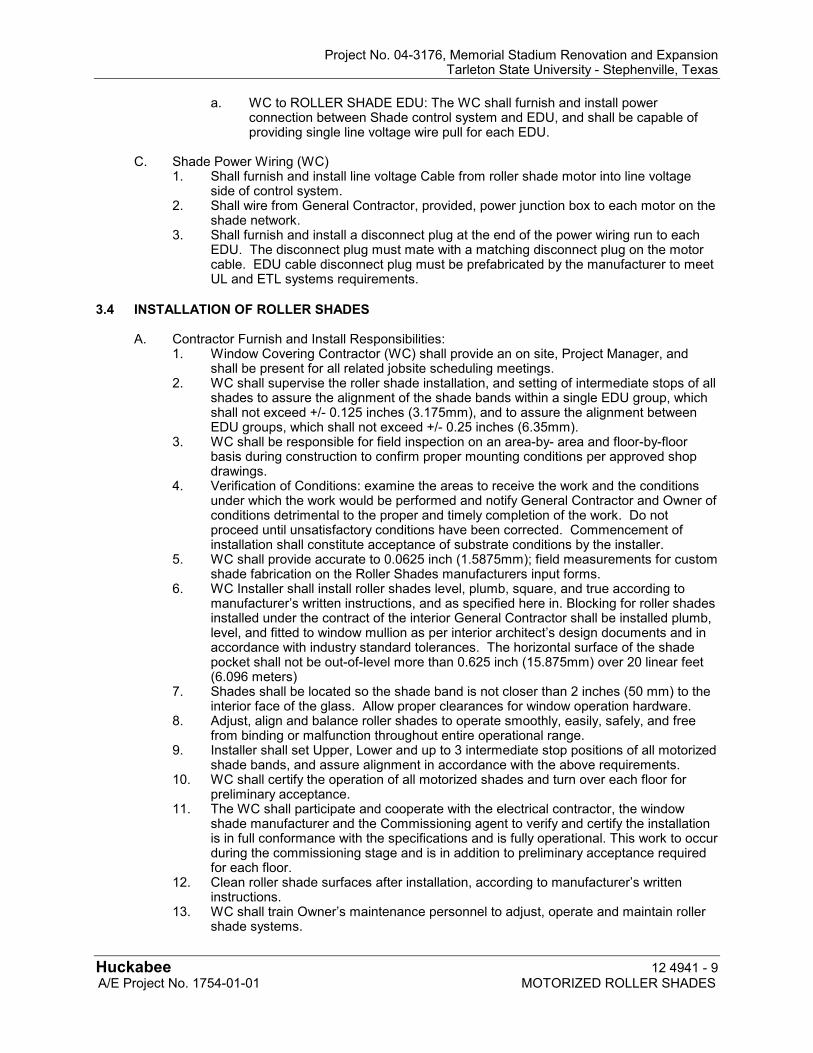
Project No. 04-3176, Memorial Stadium Renovation and Expansion Tarleton State University - Stephenville, Texas
Huckabee 12 4941 - 9 A/E Project No. 1754-01-01 MOTORIZED ROLLER SHADES
a. WC to ROLLER SHADE EDU: The WC shall furnish and install power connection between Shade control system and EDU, and shall be capable of providing single line voltage wire pull for each EDU.
C. Shade Power Wiring (WC) 1. Shall furnish and install line voltage Cable from roller shade motor into line voltage
side of control system. 2. Shall wire from General Contractor, provided, power junction box to each motor on the
shade network. 3. Shall furnish and install a disconnect plug at the end of the power wiring run to each
EDU. The disconnect plug must mate with a matching disconnect plug on the motor cable. EDU cable disconnect plug must be prefabricated by the manufacturer to meet UL and ETL systems requirements.
3.4 INSTALLATION OF ROLLER SHADES
A. Contractor Furnish and Install Responsibilities:
1. Window Covering Contractor (WC) shall provide an on site, Project Manager, and shall be present for all related jobsite scheduling meetings.
2. WC shall supervise the roller shade installation, and setting of intermediate stops of all shades to assure the alignment of the shade bands within a single EDU group, which shall not exceed +/- 0.125 inches (3.175mm), and to assure the alignment between EDU groups, which shall not exceed +/- 0.25 inches (6.35mm).
3. WC shall be responsible for field inspection on an area-by- area and floor-by-floor basis during construction to confirm proper mounting conditions per approved shop drawings.
4. Verification of Conditions: examine the areas to receive the work and the conditions under which the work would be performed and notify General Contractor and Owner of conditions detrimental to the proper and timely completion of the work. Do not proceed until unsatisfactory conditions have been corrected. Commencement of installation shall constitute acceptance of substrate conditions by the installer.
5. WC shall provide accurate to 0.0625 inch (1.5875mm); field measurements for custom shade fabrication on the Roller Shades manufacturers input forms.
6. WC Installer shall install roller shades level, plumb, square, and true according to manufacturer’s written instructions, and as specified here in. Blocking for roller shades installed under the contract of the interior General Contractor shall be installed plumb, level, and fitted to window mullion as per interior architect’s design documents and in accordance with industry standard tolerances. The horizontal surface of the shade pocket shall not be out-of-level more than 0.625 inch (15.875mm) over 20 linear feet (6.096 meters)
7. Shades shall be located so the shade band is not closer than 2 inches (50 mm) to the interior face of the glass. Allow proper clearances for window operation hardware.
8. Adjust, align and balance roller shades to operate smoothly, easily, safely, and free from binding or malfunction throughout entire operational range.
9. Installer shall set Upper, Lower and up to 3 intermediate stop positions of all motorized shade bands, and assure alignment in accordance with the above requirements.
10. WC shall certify the operation of all motorized shades and turn over each floor for preliminary acceptance.
11. The WC shall participate and cooperate with the electrical contractor, the window shade manufacturer and the Commissioning agent to verify and certify the installation is in full conformance with the specifications and is fully operational. This work to occur during the commissioning stage and is in addition to preliminary acceptance required for each floor.
12. Clean roller shade surfaces after installation, according to manufacturer’s written instructions.
13. WC shall train Owner’s maintenance personnel to adjust, operate and maintain roller shade systems.
Project No. 04-3176, Memorial Stadium Renovation and Expansion Tarleton State University - Stephenville, Texas
Huckabee 12 4941 - 10 A/E Project No. 1754-01-01 MOTORIZED ROLLER SHADES
14. Protect installed products until completion of project. 15. Touch-up, repair or replace damaged products before Substantial Completion.
3.5 PROTECTION
A. Protect installed products until completion of project.
B. Touch-up, repair or replace damaged products before Substantial Completion.
END OF SECTION
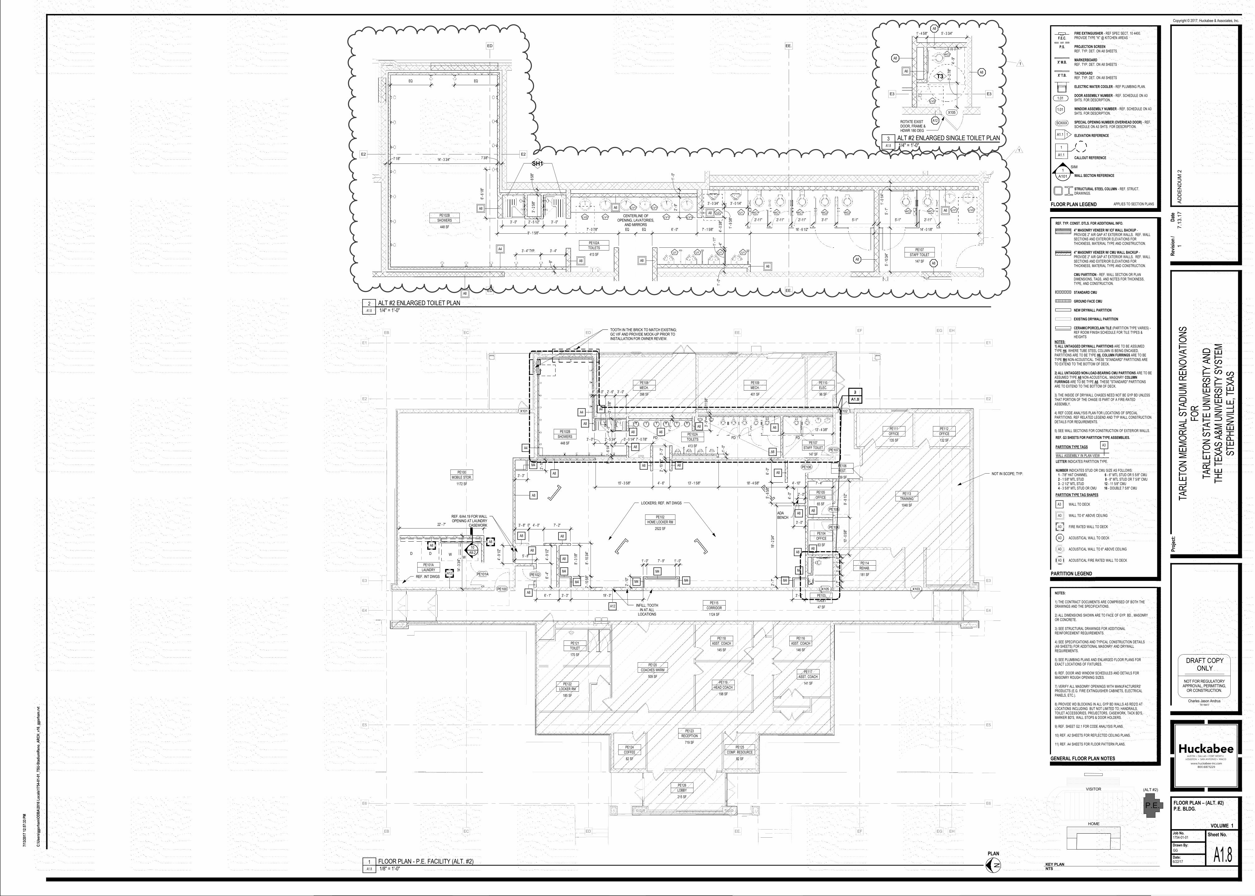
PARTITION TYPE TAGS A3
LETTER INDICATES PARTITION TYPE.
NUMBER INDICATES STUD OR CMU SIZE AS FOLLOWS: 1 - 7/8" HAT CHANNEL 6 - 6" MTL STUD OR 5 5/8" CMU 2 - 1 5/8" MTL STUD 8 - 8" MTL STUD OR 7 5/8" CMU 3 - 2 1/2" MTL STUD 12 - 11 5/8" CMU 4 - 3 5/8" MTL STUD OR CMU 16 - DOUBLE 7 5/8" CMU
WALL ASSEMBLY IN PLAN VIEW
REF. TYP. CONST. DTLS. FOR ADDITIONAL INFO.
PARTITION LEGEND
4" MASONRY VENEER W/ ICF WALL BACKUP -PROVIDE 2" AIR GAP AT EXTERIOR WALLS. REF. WALLSECTIONS AND EXTERIOR ELEVATIONS FORTHICKNESS, MATERIAL TYPE AND CONSTRUCTION.
4" MASONRY VENEER W/ CMU WALL BACKUP -PROVIDE 2" AIR GAP AT EXTERIOR WALLS. REF. WALLSECTIONS AND EXTERIOR ELEVATIONS FORTHICKNESS, MATERIAL TYPE AND CONSTRUCTION.
CMU PARTITION - REF. WALL SECTION OR PLANDIMENSIONS, TAGS, AND NOTES FOR THICKNESS,TYPE, AND CONSTRUCTION.
STANDARD CMU
GROUND FACE CMU
NEW DRYWALL PARTITION
EXISTING DRYWALL PARTITION
CERAMIC/PORCELAIN TILE (PARTITION TYPE VARIES) -REF ROOM FINISH SCHEDULE FOR TILE TYPES &HEIGHTS
PARTITION TYPE TAG SHAPES
REF. G3 SHEETS FOR PARTITION TYPE ASSEMBLIES.
A3
A3
A3
A3
A3
A3
NOTES:1) ALL UNTAGGED DRYWALL PARTITIONS ARE TO BE ASSUMEDTYPE H4. WHERE TUBE STEEL COLUMN IS BEING ENCASED,PARTITIONS ARE TO BE TYPE H6. COLUMN FURRINGS ARE TO BETYPE M4 NON-ACOUSTICAL. THESE "STANDARD" PARTITIONS ARETO EXTEND TO THE BOTTOM OF DECK.
2) ALL UNTAGGED NON-LOAD-BEARING CMU PARTITIONS ARE TO BEASSUMED TYPE A8 NON-ACOUSTICAL. MASONRY COLUMNFURRINGS ARE TO BE TYPE A6. THESE "STANDARD" PARTITIONSARE TO EXTEND TO THE BOTTOM OF DECK.
3) THE INSIDE OF DRYWALL CHASES NEED NOT BE GYP BD UNLESSTHAT PORTION OF THE CHASE IS PART OF A FIRE-RATEDASSEMBLY.
4) REF CODE ANALYSIS PLAN FOR LOCATIONS OF SPECIALPARTITIONS. REF RELATED LEGEND AND TYP WALL CONSTRUCTIONDETAILS FOR REQUIREMENTS.
5) SEE WALL SECTIONS FOR CONSTRUCTION OF EXTERIOR WALLS.
WALL TO DECK
WALL TO 6" ABOVE CEILING
FIRE RATED WALL TO DECK
ACOUSTICAL WALL TO DECK
ACOUSTICAL WALL TO 6" ABOVE CEILING
ACOUSTICAL FIRE RATED WALL TO DECK
FIRE EXTINGUISHER - REF SPEC SECT. 10 4400.PROVIDE TYPE "K" @ KITCHEN AREAS
PROJECTION SCREENREF. TYP. DET. ON A8 SHEETS
MARKERBOARDREF. TYP. DET. ON A8 SHEETS
TACKBOARDREF. TYP. DET. ON A8 SHEETS
ELECTRIC WATER COOLER - REF PLUMBING PLAN.
DOOR ASSEMBLY NUMBER - REF. SCHEDULE ON A3SHTS. FOR DESCRIPTION.
WINDOW ASSEMBLY NUMBER - REF. SCHEDULE ON A3SHTS. FOR DESCRIPTION.
SPECIAL OPENING NUMBER (OVERHEAD DOOR) - REF.SCHEDULE ON A3 SHTS. FOR DESCRIPTION.
ELEVATION REFERENCE
CALLOUT REFERENCE
WALL SECTION REFERENCE
STRUCTURAL STEEL COLUMN - REF. STRUCT.DRAWINGS.
FLOOR PLAN LEGEND APPLIES TO SECTION PLANS
F.E.C.
A1.1 1
1
A101
SIM
X' M.B.
P.S.
X' T.B.
1
A1.1
1.01
1.01
SOXXX
2522 SF
HOME LOCKER RM
PE102
63 SF
OFFICE
PE104
65 SF
OFFICE
PE105
139 SF
VEST.
PE106
47 SF
TOILET
PE103
413 SF
TOILETS
PE102A
448 SF
SHOWERS
PE102B
147 SF
STAFF TOILET
PE107
275 SF
LAUNDRY
PE101A
1172 SF
MOBILE STOR.
PE100
PE107
PE106
PE104
PE105
PE102
PE100
398 SF
MECH.
PE108
401 SF
MECH.
PE109
96 SF
ELEC.
PE110
135 SF
OFFICE
PE111
132 SF
OFFICE
PE112
1048 SF
TRAINING
PE113
181 SF
REHAB.
PE114
146 SF
ASST. COACH
PE116
1124 SF
CORRIDOR
PE115
145 SF
ASST. COACH
PE118
509 SF
COACHES WKRM
PE120
198 SF
HEAD COACH
PE119
170 SF
TOILET
PE121
185 SF
LOCKER RM
PE122
719 SF
RECEPTION
PE123
82 SF
COFFEE
PE124
82 SF
COMP. RESOURCE
PE125
141 SF
ASST. COACH
PE117
215 SF
LOBBY
PE126
E1E1
E2E2
E3E3
E4E4
E5E5
E6E6
EG
EG
EH
EH
EF
EF
EE.
EE.
ED
ED
EC
EC
EB
EB
X101 X102
22' - 7"
14' -
3 3
/4"
5' - 8"
4' -
9 1/
2"6'
- 4"
8' -
10 3
/4"
3' -
1 7/
8"4'
- 0"
2' -
6 1/
4"8"
13' - 4 3/8"
4' - 10" 7' - 4"
6' -
0"2' -
10 1
/2"
9' -
8 1/
2"10
' - 0
5/8
"
11 5
/8"
3' -
9"
PE101A
X103
5' -
6 5/
8"
3' - 0"
1' -
5"3'
- 4"
7' - 2"4' - 0"0"3' - 8"
2' -
10 5
/8"
19' - 3"3' - 3"
2' -
10"
1' - 0" 7' - 9" 1' - 0"
3' - 5"
2' -
7"19
' - 2
3/4
"
2' -
10"
3' - 3"
6' - 1"
3' - 0"2' - 6"3' - 0"8"
A8
A8 A8
A8
A8
A8
A4
A8
A8
A8
M4
A8A8
A8
A8
A8
M4
M4 M4
M4
M4 M4
M4
A8A8
A8
A8A8
1' -
0"
1' -
0"
8' -
3 1/
8"
1' -
7"
3' -
3"
A6
18' - 4 5/8"13' - 1 5/8"4' - 6"15' - 3 5/8"
A12 INFILL; TOOTHIN AT ALL
LOCATIONS
7' - 0 7/8"3' - 0 1/4"2' - 5 3/4"3' - 0"
A4
A6
A8
A4
FD FD FD
A8
X105
2' - 0"
4' -
0"
4' -
9 1/
2"
10
A9.2
A12
TOOTH IN THE BRICK TO MATCH EXISTING;GC VIF AND PROVIDE MOCK-UP PRIOR TOINSTALLATION FOR OWNER REVIEW.
REF. 6/A4.19 FOR WALLOPENING AT LAUNDRY
CASEWORK
ADABENCH
A1.8
2
WW
DD
REF. INT DWGS
LOCKERS; REF. INT DWGS
A1.8
3
NOT IN SCOPE; TYP.
GENERAL FLOOR PLAN NOTES
NOTES:
1) THE CONTRACT DOCUMENTS ARE COMPRISED OF BOTH THEDRAWINGS AND THE SPECIFICATIONS.
2) ALL DIMENSIONS SHOWN ARE TO FACE OF GYP. BD., MASONRYOR CONCRETE.
3) SEE STRUCTURAL DRAWINGS FOR ADDITIONALREINFORCEMENT REQUIREMENTS.
4) SEE SPECIFICATIONS AND TYPICAL CONSTRUCTION DETAILS(A9 SHEETS) FOR ADDITIONAL MASONRY AND DRYWALLREQUIREMENTS.
5) SEE PLUMBING PLANS AND ENLARGED FLOOR PLANS FOREXACT LOCATIONS OF FIXTURES.
6) REF. DOOR AND WINDOW SCHEDULES AND DETAILS FORMASONRY ROUGH OPENING SIZES.
7) VERIFY ALL MASONRY OPENINGS WITH MANUFACTURERS'PRODUCTS (E.G. FIRE EXTINGUISHER CABINETS, ELECTRICALPANELS, ETC.).
8) PROVIDE WD BLOCKING IN ALL GYP BD WALLS AS REQ'D ATLOCATIONS INCLUDING BUT NOT LIMITED TO; HANDRAILS,TOILET ACCESSORIES, PROJECTORS, CASEWORK, TACK BD'S,MARKER BD'S, WALL STOPS & DOOR HOLDERS.
9) REF. SHEET G2.1 FOR CODE ANALYSIS PLANS.
10) REF. A2 SHEETS FOR REFLECTED CEILING PLANS.
11) REF. A4 SHEETS FOR FLOOR PATTERN PLANS.
E2E2
EE.
EE.
ED
ED
147 SF
STAFF TOILET
PE107
413 SF
TOILETS
PE102A
448 SF
SHOWERS
PE102B
1' -
0 1/
4"5'
- 1"
5' -
10 3
/4"
1' -
9 3/
8"
4' -
0 3/
8"4"1' -
11"
1' -
0"
1' -
0"2'
- 9"
8"
8 5/
8"3'
- 2
5/8"
7 1/8" 14' - 3 3/4" 7 3/8"
9' - 1 5/8"7' - 0 7/8" EQ EQ 6' - 0" 7' - 1 5/8" 16' - 6 1/2" 14' - 0 1/8"
CENTERLINE OFOPENING, LAVATORIES,
AND MIRRORS
5'-1" 2'-11"2'-11" 2'-11" 2'-11" 3'-1" 5'-1"
3' - 0 1/4"3' - 0 3/4"
3' - 0"2' - 5 1/2"3' - 0"
3' - 4" TYP. 3' - 4"
6' -
6 1/
8"
EQEQ
A8A8
A6A8
A6
A8A8
A4
A8
A8 A6WC1WC2
LV2LV1WC2WC2WC1WC1WC1U1U2
LV2 LV1 LV1LV1
LV1LV1
U1 U1 U1 U1
SH1
E3E3
X105
ROTATE EXISTDOOR, FRAME &HDWR 180 DEG
4' -
9"3'
- 2
7/8"
5' - 3 3/4"1' - 4 5/8"
A8
A8
A8
A12
A6
WC2
T3
LV2
NOT FOR REGULATORYAPPROVAL, PERMITTING,
OR CONSTRUCTION.
DRAFT COPYONLY
Charles Jason AndrusTX 19417
Sheet No.Job No.
Drawn By:
Date:
Pro
ject
:
Copyright © 2017, Huckabee & Associates, Inc.
VOLUME
C:\
Use
rs\g
go
rham
\OD
BA
\201
6 L
oca
ls\1
754-
01-0
1_T
SU
-Sta
diu
mR
eno
_AR
CH
_v16
_gg
orh
am.r
vt
7/13
/201
7 12
:57:
33 P
M
GG
A1.8
FLOOR PLAN – (ALT. #2)P.E. BLDG.
6/22/17
1754-01-01
TAR
LETO
N M
EM
OR
IAL
STA
DIU
M R
EN
OV
ATI
ON
SFO
RTA
RLE
TON
STA
TE U
NIV
ER
SIT
Y A
ND
THE
TE
XA
S A
&M
UN
IVE
RS
ITY
SY
STE
MS
TEP
HE
NV
ILLE
, TE
XA
S
1HOME
KEY PLANNTS
P.E.
VISITOR (ALT #2)
A1.8 1/8" = 1'-0"
1 FLOOR PLAN - P.E. FACILITY (ALT. #2)
N
PLAN
Rev
isio
n /
Dat
e
17.1
3.1
7A
DD
EN
DU
M 2
A1.8 1/4" = 1'-0"
2 ALT #2 ENLARGED TOILET PLAN
A1.8 1/4" = 1'-0"
3 ALT #2 ENLARGED SINGLE TOILET PLAN
1
1

Project Name: Tarleton Memorial Stadium Renovations Client: Tarleton State University and the Texas A&M University System Stephenville, Texas Project Number: 1754-01-01
Technology Items For Addendum No. 1
Page 1 of 1
TECHNOLOGY ITEMS FOR ADDENDUM NO. 2 NOTICE TO PROPOSERS:
A. This Addendum shall be considered part of the contract documents for the above-mentioned project as though it had been issued at the same time and incorporated integrally therewith. Where provisions of the following supplementary data differ from those of the original contract documents, this Addendum shall govern and take precedence.
B. Proposers are hereby notified that they shall make any necessary adjustments in their estimate on account of this Addendum. It will be construed that each Proposer’s proposal is submitted with full knowledge of all modifications and supplemental data specified therein. Acknowledge receipt of this addendum in the space provided on the proposal form. Failure to do so may subject Proposer to disqualification.
REFERENCE IS MADE TO THE PROJECT MANUAL AS NOTED: SPECIFICATIONS:
AD No. 2, Tech. Item 1. To the Specifications, Section 28 13 00, “ACCESS CONTROL” Reference section 1.4 Qualifications; Cbord is the manufacturer of the existing access control system at TSU. This project shall function as an extension of the existing system on-campus and the contractor must be certified by Cbord.
END OF TECHNOLOGY ADDENDUM


![[ ADDENDUM ]](https://img.pdfslide.net/doc/110x75/61bd25c261276e740b0fd851/-addendum-.jpg)