Embed Size (px)
Citation preview

WEST HARRIS COUNTY REGIONAL WATER AUTHORITY ADDENDUM No. 2
ADDENDUM NO. 2
Issue Date: April 12, 2021
Project: West Harris County Regional Water Authority
Surface Water Supply Project
Contract S3-A3
From: Dannenbaum Engineering Corporation
3100 West Alabama
Houston, TX 77098
To: Prospective Bidders
This Addendum forms a part of the Bidding Documents and will be incorporated into the Contract
documents, as applicable. Insofar as the original Project Manual and Drawings are inconsistent, this
Addendum governs. Acknowledge receipt of the Addendum by inserting its number and date of issue in
the Agreement Between Owner and Contractor under Exhibit 1 – Contractor’s Bid. FAILURE TO DO SO
WILL SUBJECT BID TO DISQUALIFICATION.
This Addendum uses the change page method: remove and replace or add pages, or Drawing sheets,
as directed in the change instructions below. Change bars ( | ) are provided in the outside margins
of pages from the Project Manual to indicate where changes have been made; no change bars are
provided in added Sections. Reissued Drawing Sheets show the Addendum number below the title
block and changes in the Drawing are noted by a revision mark and enclosed in a revision cloud.
PART 1 – PROJECT MANUAL
1.1 Remove Page 1 of Agreement Between Owner and Contractor For Construction Contract
(Stipulated Price) and replace with the attached Page 1 of said document.
1.2 Add attached Geotechnical Baseline Report Document after Appendix III – Geotechnical
Baseline Report.
PART 2 – DRAWINGS
2.1 Remove Drawing No. TU-012 and replace with the attached Drawing No. TU-012.
END OF ADDENDUM NO. 2

Agreement Between Owner and Contractor (Segment 3, Contract S3-A3) Page 1 of 27 4819-4443-7105v.1 Addendum No. 2
AGREEMENT BETWEEN OWNER AND CONTRACTOR
FOR CONSTRUCTION CONTRACT (STIPULATED PRICE)
THIS AGREEMENT is by and between West Harris County Regional Water Authority
(“Owner” or “Authority”) and
(“Contractor”).
Owner and Contractor hereby agree as follows:
ARTICLE 1 – WORK
Contractor shall complete all Work as specified or indicated in the Contract Documents for completion of the Project.
ARTICLE 2 – THE PROJECT
2.01 The Project, of which the Work under the Contract Documents is a part, is generally described as the Segment 3 project, which is one of multiple, interdependent projects comprising the overall Surface Water Supply Project (“Surface Water Supply Project” or “SWSP”), which will deliver surface water to the Owner and the North Fort Bend Water Authority (“NFBWA”).
ARTICLE 3 – DESIGN PROFESSIONAL OF RECORD AND ENGINEER
3.01 The part of the Project that pertains to the Work has been designed by Freese and Nichols, Inc., which is hereinafter referred to as the “Design Professional of Record” or the “DPOR.”
3.02 The Owner has retained Dannenbaum Engineering Corporation (“Engineer”) to act as Owner’s representative, assume all duties and responsibilities, and have the rights and authority assigned to Engineer in the Contract Documents in connection with the completion of the Work in accordance with the Contract Documents.
ARTICLE 4 – CONTRACT TIMES
4.01 Time of the Essence
A. All time limits for Milestones, if any, Substantial Completion, and completion and readiness for Final Payment as stated in the Contract Documents are of the essence of the Contract.
4.02 Contract Times: Days
A. The Work will achieve Substantial Completion within 360 days after the date when the Contract Times commence to run as provided in Paragraph 4.01 of the General Conditions. The Work will achieve Final Completion in accordance with Paragraph 15.06 of the General Conditions within 390 days after the date when the Contract Times commence to run.
4.03 Liquidated Damages/Economic Disincentives
A. The pecuniary damages suffered by Owner for late completion are by their very nature difficult to ascertain precisely. It is therefore expressly agreed as a part of the consideration inducing Owner to execute this Contract that Contractor shall owe to Owner, and Owner may

SURFACE WATER SUPPLY PROJECT
CONTRACT S3-A3
GEOTECHNICAL BASELINE REPORT
Prepared for:
West Harris County Regional Water Authority
April 12, 2021
Prepared by:
FREESE AND NICHOLS, INC. 10497 Town and Country Way, Suite 500
Houston, TX 77024 713-600-6800

SURFACE WATER SUPPLY PROJECT CONTRACT S3-A3
GEOTECHNICAL BASELINE REPORT Prepared for:
West Harris County Regional Water Authority
QC Review: Brian Gettinger, P.E.
Revised: April 12, 2021
Prepared by:
FREESE AND NICHOLS, INC. 10497 Town and Country Way, Suite 500
Houston, TX 77024
WHC18747
04/12/2021
FREESE AND NICHOLS, INC. TEXAS REGISTERED ENGINEERING
FIRM F- 2144
04/12/2021
FREESE AND NICHOLS, INC. TEXAS REGISTERED ENGINEERING
FIRM-2144

Surface Water Supply Project – Contract S3-A3 West Harris County Regional Water Authority
i
TABLE OF CONTENTS
1.0 PURPOSE ...................................................................................................................................................... 1
2.0 INTRODUCTION ......................................................................................................................................... 3
2.1 PROJECT DESCRIPTION ...................................................................................................................... 3
2.2 SCOPE ........................................................................................................................................................ 4
2.3 RELATION TO CONTRACT DOCUMENTS ..................................................................................... 4
2.4 REPORT ORGANIZATION ................................................................................................................... 5
3.0 PROJECT COMPONENTS ......................................................................................................................... 6
3.2 LOCATION OF TUNNELS .................................................................................................................... 7
3.3 LOCATION OF SHAFTS ........................................................................................................................ 9
4.0 PROJECT GEOLOGY ............................................................................................................................... 10
4.1 GEOLOGIC SETTING .......................................................................................................................... 10
4.2 FAULTING ............................................................................................................................................. 10
4.3 GROUNDWATER ................................................................................................................................. 11
5.0 CHARACTERIZATION AND BEHAVIOUR OF SUBSURFACE STRATA ................................. 12
5.1 PROPERTIES AND BEHAVIOR OF SUBSURFACE STRATA ................................................. 12
5.1.1 Subsurface Material 1 – Clay..................................................................................................13
5.1.2 Subsurface Material 2 – Sand ................................................................................................17
5.1.3 Subsurface Material 3 – Cemented Sand ...........................................................................17
6.0 DESIGN AND CONSTRUCTION CONSIDERATIONS ................................................................... 18
6.1 EXCAVATION AND GROUND SUPPORT OF TUNNELS ......................................................... 18
6.2 EXCAVATION AND GROUND SUPPORT OF SHAFTS ............................................................. 18
6.3 PETROLEUM CONTAMINATION .................................................................................................. 19
6.4 STRUCTURES, UTILITIES AND OBSTRUCTIONS .................................................................... 19
6.5 GROUND WATER INFLOW ............................................................................................................. 20
6.6 FLOODING ............................................................................................................................................. 20
6.7 APPLICATION OF BASELINES ....................................................................................................... 20
7.0 DISCLAIMER ............................................................................................................................................. 21
Table of Figures Figure 1. SWSP Contract S3-A3 ....................................................................................................... 4
Figure 2. Location of Tunnels .......................................................................................................... 7

Surface Water Supply Project – Contract S3-A3 West Harris County Regional Water Authority
ii
Figure 3. Boring Locations Relative to Tunnel Crossings .............................................................. 11
Figure 4. Variation of Plasticity Index for Subsurface Material 1 ................................................. 14
Figure 5. Clogging Potential of all Subsurface Material 1 Samples .............................................. 16
Figure 6. Clogging Potential of Subsurface Material 1 Samples from Tunnel Zones. ................... 16
Table of Tables
Table 1. Contract S3-A3 Tunnel Information .................................................................................. 6
Table 2. Trenchless Construction next to Electrical Towers ........................................................... 6
Table 3. Summary of Groundwater (GW) Measurements ........................................................... 12
Table 4. Baseline Values for Subsurface Material 1 ..................................................................... 14
Table 5. Baseline Values for Subsurface Material 2 ..................................................................... 17
Table 6. Baseline Values for Subsurface Material 3 ..................................................................... 17
Table 7. Baseline Percentages of Subsurface Materials Encountered in Tunnels ........................ 18
Table 8. Baseline Percentages of Subsurface Materials Encountered in Shafts .......................... 18 APPENDICES Appendix A: Tunnelman’s Ground Classification Table
Appendix B: Boring Logs with Tunnel Envelope
Surface Water Supply Project – Contract S3-A3 West Harris County Regional Water Authority
1
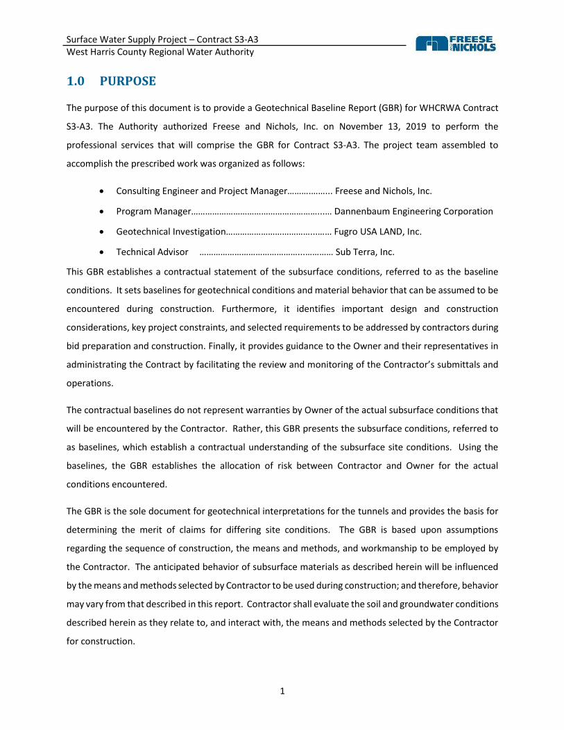
1.0 PURPOSE
The purpose of this document is to provide a Geotechnical Baseline Report (GBR) for WHCRWA Contract
S3-A3. The Authority authorized Freese and Nichols, Inc. on November 13, 2019 to perform the
professional services that will comprise the GBR for Contract S3-A3. The project team assembled to
accomplish the prescribed work was organized as follows:
• Consulting Engineer and Project Manager……….……... Freese and Nichols, Inc.
• Program Manager………………………………………………...… Dannenbaum Engineering Corporation
• Geotechnical Investigation………………………………...…… Fugro USA LAND, Inc.
• Technical Advisor ……………………………………...………… Sub Terra, Inc.
This GBR establishes a contractual statement of the subsurface conditions, referred to as the baseline
conditions. It sets baselines for geotechnical conditions and material behavior that can be assumed to be
encountered during construction. Furthermore, it identifies important design and construction
considerations, key project constraints, and selected requirements to be addressed by contractors during
bid preparation and construction. Finally, it provides guidance to the Owner and their representatives in
administrating the Contract by facilitating the review and monitoring of the Contractor’s submittals and
operations.
The contractual baselines do not represent warranties by Owner of the actual subsurface conditions that
will be encountered by the Contractor. Rather, this GBR presents the subsurface conditions, referred to
as baselines, which establish a contractual understanding of the subsurface site conditions. Using the
baselines, the GBR establishes the allocation of risk between Contractor and Owner for the actual
conditions encountered.
The GBR is the sole document for geotechnical interpretations for the tunnels and provides the basis for
determining the merit of claims for differing site conditions. The GBR is based upon assumptions
regarding the sequence of construction, the means and methods, and workmanship to be employed by
the Contractor. The anticipated behavior of subsurface materials as described herein will be influenced
by the means and methods selected by Contractor to be used during construction; and therefore, behavior
may vary from that described in this report. Contractor shall evaluate the soil and groundwater conditions
described herein as they relate to, and interact with, the means and methods selected by the Contractor
for construction.

Surface Water Supply Project – Contract S3-A3 West Harris County Regional Water Authority
2
Any means and methods proposed by Contractor where Contractor believes the baseline becomes invalid
or requires modification shall be raised by the Contractor and discussed during the bid phase prior to bid
opening. Contractor has a duty to inform Owner of the baselines the Contractor believes are invalid or
require modification during the bid phase.

Surface Water Supply Project – Contract S3-A3 West Harris County Regional Water Authority
3
2.0 INTRODUCTION
2.1 PROJECT DESCRIPTION
The West Harris County Regional Water Authority (WHCRWA or the Authority) Contract S3-A3 is a part of
the Surface Water Supply Program (SWSP) being developed by the Authority to prepare the area for
mandated conversion from groundwater to surface water. These conversion goals and respective dates
are in accordance with requirements set forth by the Harris-Galveston Coastal Subsidence District
(HGSCD).
The WHCRWA SWSP was designed to support 30 percent of the total water demand within the boundaries
of the WHCRWA by the year 2010. To meet the mandates set forth by the HGCSD, the Authority must
construct the facilities necessary to transmit surface water to users within the Authority’s boundaries. The
WHCRWA is currently planning, designing, and constructing various elements of a surface water
transmission system for this purpose. The system is being constructed to coincide with the HGCSD
conversion requirements and dates, with the ultimate system provided capable of supporting a minimum
of 80 percent of the total water demand by and beyond the year of 2030.
The Authority retained the services of Dannenbaum Engineering Company (DEC) to serve as Program
Manager throughout the development of infrastructure and conversion to surface water. Under the
direction of DEC, sub-consultants assisting in the Authority’s efforts have prepared system models and
provided required pipeline sizes for individual segments within the system, including those represented
by WHCRWA Contract S3-A3. The general alignment of Contract S3-A3 is presented on Figure 1.

Surface Water Supply Project – Contract S3-A3 West Harris County Regional Water Authority
4
Figure 1. SWSP Contract S3-A3
2.2 SCOPE
This GBR only pertains to the Tunnel Locations of the SWSP Contract S3-A3 Project, as defined in Section
3.1
2.3 RELATION TO CONTRACT DOCUMENTS
The GBR references the Geotechnical Data Report (GDR) – West Harris County Regional Water Authority
– Contract S3-A3, dated July 19, 2019, prepared by Fugro USA LAND, Inc. The GDR presents the factual
details of the geotechnical field investigations completed at the project site. Included in the GDR are the
results of the laboratory testing performed on soil samples collected during the investigations and
detailed descriptions of the field and laboratory testing data, methods, and procedures. This GBR and the
S3-A3

Surface Water Supply Project – Contract S3-A3 West Harris County Regional Water Authority
5
GDR are Contract Documents. If there are any inconsistencies between the GBR and GDR, the GBR shall
take precedence.
The GBR is not intended to present the minimum required design standards of construction contained in
the Contract Documents. Nothing in this GBR should be construed as amending or altering the Plans and
Specifications or relaxing the standards of construction.
The technical concepts, terms, and descriptions in this report follow standards commonly used in
geotechnical engineering and engineering geology, which have specific meaning pertaining to the work.
It is recommended that Contractors have a qualified geotechnical engineer or engineering geologist
carefully review the GBR so that a complete understanding of the information presented in this report is
developed prior to submitting a bid.
2.4 REPORT ORGANIZATION
This GBR report generally follows the guidelines contained in the American Society of Civil Engineers
document titled Geotechnical Baseline Reports for Construction, dated 2007, and is comprised of Report
Purpose (Section 1) and the following five sections (Sections 2 through 6) as detailed below:
• Section 2, Introduction, presents detailed descriptions about the project location, scope,
components, and requirements.
• Section 3, Project Components, presents descriptions of the tunnels and shafts including method
of excavation.
• Section 4, Project Geologic Setting, describes the project setting including geological
considerations, soil conditions and ground water locations. It also includes a summary of the
available data from the GDR.
• Section 5, Characterization and Behavior of Subsurface Strata, presents the characterization,
behavior, and baselines of material types present along the project alignment.
• Section 6, Design and Construction Considerations, presents the considerations and baselines
relating to construction of the Project tunnels and shafts.
In summary, Sections 5 and 6 contain the Baselines that have been set for this project.

Surface Water Supply Project – Contract S3-A3 West Harris County Regional Water Authority
6
3.0 PROJECT COMPONENTS
The proposed tunnel crossings along the S3-A3 pipeline are presented in Table 1.
Table 1. Contract S3-A3 Tunnel Information
Tunnel Primary
Liner Diameter
(in) Beginning
STA Ending STA Length (ft) H – Depth* (ft)
Buffalo Bayou Casing 60 5+70 13+58 788 52.3
Wycliffe Casing or Liner
Plate
60 15+94 17+05 111 21.4
Memorial Casing 60 40+40 42+32 192 53.5
Rummel Creek Casing 60 47+93 55+96 703 35.2
Barry Knoll Casing or Liner
Plate
60 59+45 60+26 81 30.9
St Mary’s Casing or Liner
Plate
60 72+19 73+03 84 30.0
IH-10 Casing 60 82+10 87+30 520 37.3
* Maximum depth based on ground level to invert of tunnel liner/casing
In addition to the tunnels in Table 1, the S3-A3 waterline will pass seven (7) electrical towers, each
requiring trenchless excavation. The length of the electrical tower tunnels is generally 75 feet. As
prescribed in the Contract Documents, the primary liner will be 60-inch steel casing pipe. The electrical
tower trenchless construction will occur at the following locations shown in Table 2.
Table 2. Trenchless Construction next to Electrical Towers
Beginning
STA
Ending STA Length, ft Tower (TWR) Fugro Boring
1+24 1+95 71 04699 BH S3A-3-15
20+41 21+16 75 04702 BH S3A-3-12
27+23 27+98 75 04703 BH S3A-3-11
34+31 35+06 75 04704 None
61+70 62+45 75 04708 None
68+61 69+36 1 75 04709 BH S3A-3-05
75+77 76+52 75 04710 BH S3A-3-03
1. Extension of Long Point Fault casing

Surface Water Supply Project – Contract S3-A3 West Harris County Regional Water Authority
7
3.2 LOCATION OF TUNNELS
This GBR is focused on the S3-A3 tunnels of significant length and/or risk of impacts to existing
infrastructure and/or utilities. Baselines included herein only apply to the tunnels shown in Figure 2.
Figure 2. Location of Tunnels
• Interstate 10 (IH-10): The crossing of IH-10 will be tunneled. The tunnel will begin at STA 82+10
and end at STA 87+30. The total tunnel length is 520 feet. The tunnel depth is controlled by a 30”
Sanitary Line on the north side of the crossing. The depth of this tunnel varies between 28.9 and
37.3 feet. The Contract Documents specify construction using pressurized face methods and
Buffalo Bayou
Tunnel Crossing
Memorial Drive
Tunnel Crossing
IH-10 Tunnel
Crossing
Rummel Creek
Tunnel Crossing
S3-A3

Surface Water Supply Project – Contract S3-A3 West Harris County Regional Water Authority
8
watertight shafts with break in/out plugs and bottom seals. The primary liner will be 60” steel
casing pipe.
• Rummel Creek: The crossing of Rummel Creek will be tunneled. The tunnel will begin at STA 47+93
and end at STA 55+96. The total tunnel length is 703 feet. The tunnel depth is controlled by the
recommended clearance needed below the bottom depth of Rummel Creek. The tunnel depth
varies between 15.0 and 35.2 feet. The Contract Documents specify construction using
pressurized face methods and watertight shafts with break in/out plugs and bottom seals. The
primary liner will be 60” steel casing pipe.
• Memorial Drive: The crossing of Memorial Drive will be tunneled. The tunnel will begin at STA
40+40 and end at STA 42+32. The total tunnel length is 192 feet. The tunnel depth is controlled
by the presence of a High Volatile Organic Compound (VOC) Soil Layer. The tunnel depth varies
between 48.7 and 53.5 feet. The Contract Documents specify construction using pressurized face
methods and watertight shafts with break in/out plugs and bottom seals. The primary liner will
be 60” steel casing pipe.
• Buffalo Bayou: The crossing of Buffalo Bayou will be tunneled. The tunnel will begin at STA 5+70
and end at STA 13+58. The total tunnel length is 788 feet. The tunnel depth is controlled by the
recommended clearance needed below the bottom depth of Buffalo Bayou. The tunnel depth
varies between15.1 and 52.3 feet. The Contract Documents specify construction using pressurized
face methods and watertight shafts with break in/out plugs and bottom seals. The primary liner
will be 60” steel casing pipe.
Construction should not cause any portion of the crossed streets to be closed to through traffic. Traffic
Control Plans within the Contract Documents provide safety procedures for vehicles passing through the
area or accessing the construction sites.
Soils encountered through geotechnical borings along the proposed alignment within the area of
construction vary from boring to boring. For a more detailed description of the soils along the proposed
alignment, please refer to the GDR.

Surface Water Supply Project – Contract S3-A3 West Harris County Regional Water Authority
9
3.3 LOCATION OF SHAFTS
The limits of tunnel shaft construction are 30 feet by 30 feet centered on the pipeline and beginning at
each end of the tunnel. The shape and size of the tunnel shafts are to be determined by the tunnel
contractor but must fit within 30 feet by 30 feet limits. Shaft design must be performed, sealed and signed
by an appropriately qualified professional engineer registered in the State of Texas. Every shaft must be
watertight with tunnel break in/out plugs and a bottom seal. Below is a description of the expected shafts.
All shaft bottom elevations include over excavation for backfill and a seal slab and are 2 feet below the
invert of the tunnel lining/casing.
IH-10: The tunnel shaft limits will begin at STA 87+30 and end at STA 87+60 for the launching shaft and
begin at STA 81+80 and end at STA 82+10 for the receiving shaft. The bottom of the shafts will be at
elevation 51.7 feet for the launching shaft and elevation 54.8 feet for the receiving shaft. Access to the
launch shaft will be south on the ROW from an existing driveway on the westbound IH-10 Frontage Road
and access to the retrieval shaft will be north on the ROW from the westbound IH-10 Frontage Road.
Rummel Creek: The tunnel shaft limits will begin at STA 47+63 and end at STA 47+93 for the launching
shaft and begin at STA 55+96 and end at STA 56+26 for the receiving shaft. The bottom of the shafts will
be at elevation 37.3 feet for the launching shaft and elevation 38.1 feet for the receiving shaft. Access to
the shafts will be north on the ROW from Memorial Drive for the launching shaft and south on the ROW
from Barry Knoll Lane for the receiving shaft.
Memorial Drive: The tunnel shaft limits will begin at STA 40+10 and end at STA 40+40 for the launching
shaft and begin at STA 42+32 and end at STA 42+62 for the receiving shaft. The bottom of the shafts will
be at elevation 47.3 feet for the launching shaft and elevation 47.5 feet for the receiving shaft. Access to
the shafts will be from Memorial Drive for both the launching and receiving shafts. Spoils from shaft
construction must be disposed of per potentially petroleum contaminated areas (PPCA) requirements set
in the specifications.
Buffalo Bayou: The tunnel shaft limits will begin at STA 5+40 and end at STA 5+70 for the launching shaft
and begin at STA 13+58 and end at STA 13+88 for the receiving shaft. The bottom of the shafts will be at
elevation 18.7 feet for the launching shaft and elevation 19.5 feet for the receiving shaft. Access to the
shafts will be north on the ROW from Lakeside Forest Lane for the launching shaft and south on the ROW
from Indian Creek Road for the receiving shaft.

Surface Water Supply Project – Contract S3-A3 West Harris County Regional Water Authority
10
4.0 PROJECT GEOLOGY
4.1 GEOLOGIC SETTING
A geologic write-up for the regional and site geology is presented in the GDR. Portions of the text from
the GDR are reproduced in the following paragraphs for convenience of the reader. Some of the text has
been slightly modified to aid the selected test to transition between segments since the entire geologic
section has not been reproduced herein. Please refer to the GDR for the detailed geologic discussion.
“Harris County is located within the Gulf Coastal Plain of Texas. Overall, the region is underlain by a large
mass of sediments that, on a regional basis, are slightly inclined toward the Gulf of Mexico, with successive
order formations cropping out farther inland. The geologic units that crop out along the Segment 3-A3
alignment are deposits along the coast, bays and streams, the Beaumont and the Lissie Formations. The
Geologic Atlas of Texas, Houston Sheet, published by the Bureau of Economic Geology, Austin, Texas
reports the Beaumont Formation to be about 100 feet thick and the underlying Lissie Formation to be
about 200 feet thick. The Houston area contains these two major surface formations, the Beaumont
Formation and the Lissie Formation with more recent Holocene deposits overlying these two formations.
Based on the Geologic Atlas of Texas, the subsurface explored during the field exploration along Segment
3-A3 are within the Beaumont Formation.”
“The Beaumont Formation generally consists of low permeable, highly compressible clay with interbedded
sand deposits. The formation is generally composed of overconsolidated stiff to hard, poorly bedded,
slickensided clay, interbedded with lenses and nearly continuous layers of sand and/or silt. Thin layers of
cemented silts and sands are locally present.”
“The underlying Lissie formation is composed of interbedded clays, silts, and clayey and/or silty sands. It
generally consists of stronger clays and coarser sands and gravel. Thin layers of cemented silts and sands
are locally present.”
4.2 FAULTING
As presented in the GDR, the faults in the area of the project site do not display seismic properties, but
slow creeping movements are recorded. Evidence of modern activity of these faults includes changes in
elevation of the ground surface, offsets in pavements, and damage to buildings, bridges, and other
structures.

Surface Water Supply Project – Contract S3-A3 West Harris County Regional Water Authority
11
Risk associated with seismicity in the Houston area is considered relatively low. The Seismic Hazard Map
by the United States Geological Survey (USGS) is provided in the GDR. The map shows the Houston area
to be “Lowest Hazard.” Due to the low seismicity of the area and soil conditions, the liquefaction potential
of the soils is low.
Segment 3-A3 crosses the Long Point Fault Hazard Zone (Approximate pipeline Station 67+50 to 68+75).
The pipeline construction will include a combination of open cut trench and trenchless construction.
Tunneling within the hazard zone is not expected to adversely impact construction operations.
Fugro, Inc. prepared a Phase I Geologic Fault Study for Segment 3-A3 dated May 1, 2019. This report is
provided in the Contract Documents.
4.3 GROUNDWATER
The borings and their relation to the tunnel crossings are shown in Figure 3.
Figure 3. Boring Locations Relative to Tunnel Crossings

Surface Water Supply Project – Contract S3-A3 West Harris County Regional Water Authority
12
Table 3 below shows the short-term groundwater levels encountered at the borings drilled along the
tunnel alignment. Groundwater measurements were recorded during the field investigation and are being
monitored at six (6) locations where piezometers were installed. Those locations are indicated in Table 3.
For additional groundwater details and measurements, refer to the GDR and any supplemental reports to
the GDR.
Table 3. Summary of Groundwater (GW) Measurements Boring Purpose Ground
Surface EL (ft)
GW EL (ft)
Approx. Depth to GW (ft)1
Date of GW Measurement
Approx. EL of Tunnel Invert (ft)
GW Above Invert EL
(ft)
S3A-3-012 Tunnel IH-10 85.8 61.8 24 3/4/2019 54 7.8
S3A-3-022 85.7 63.7 22 3/1/2019 54 9.7
S3A-3-071 Tunnel Rummel
Creek
73.8 58.8 15 2/26/2019 40 18.8
S3A-3-081 72.3 57.3 15 2/25/2019 40 17.3
S3A-3-09 Tunnel Memorial Dr.
75.2 55.2 20 2/22/2019 50 5.2
S3A-3-10 75.1 53.1 22 2/20/2019 50 3.1
S3A-3-131 Tunnel Buffalo Bayou
71.4 43.4 28 3/7/2019 27 16.4
S3A-3-141 66 41 25 3/11/2019 27 14
S3A-3-15 71 49 22 3/11/2019 27 22
1. Groundwater measurements were taken at the time of drilling. 2. Piezometer installed at boring location.
The approximate tunnel envelope is indicated on the appropriate boring logs as shown in Appendix B.
Based on the groundwater observations and the approximate elevations of the tunnel inverts, the
groundwater table is above the tunnel invert at the IH-10, Rummel Creek, Memorial Drive, and Buffalo
Bayou crossings.
5.0 CHARACTERIZATION AND BEHAVIOUR OF SUBSURFACE STRATA
5.1 PROPERTIES AND BEHAVIOR OF SUBSURFACE STRATA
The soil units along the tunnel alignment will affect the selection of the Contractor’s means and methods
of excavation. Ground behavior depends upon plasticity of fine materials, gradation, consistency/relative
density (SPT N value), groundwater conditions, and construction means and methods employed by the
contractor.
For purposes of defining characteristics and behaviors of the subsurface profile, the soils occurring along
the tunnel alignment have been grouped into the following categories.

Surface Water Supply Project – Contract S3-A3 West Harris County Regional Water Authority
13
▪ Subsurface Material 1. Clay, fine grained soil – Includes silt and clay; 50% or more passing the
200-mesh sieve.
▪ Subsurface Material 2. Sand, coarse grained soil – Includes sand and gravel, fine to coarse, rock
fragments; more than 50% retained on the 200-mesh sieve.
▪ Subsurface Material 3. Cemented Sand
The tunnels and shafts will be constructed through both clay and sand and are expected to encounter,
Subsurface Materials 1, 2 and 3.
5.1.1 Subsurface Material 1 – Clay
The tunnel alignments and shafts will be excavated in Subsurface Material 1. Figure 4 presents the
variation of Plasticity Indices as developed from the laboratory tests performed on recovered soil samples
of Subsurface Material 1. Only one boring, S3A-3-01 encountered Subsurface Material 1 continuously
from the ground surface at El. 85.8 feet down to El. 18.8 feet where Subsurface Material 2 (silty sand) was
encountered. The remaining borings encountered Subsurface Material 2 beneath the clay at shallower
depths near elevations El. 70 to 55 feet. In the deeper borings, Subsurface Material 1 was once again
encountered underlying Subsurface Material 2. The properties of Subsurface Material 1 encountered by
the borings are similar in shear strength and plasticity regardless of elevation, therefore within this GBR
and for baseline purposes, Subsurface Material 1 clay has been referenced as a single unit.

Surface Water Supply Project – Contract S3-A3 West Harris County Regional Water Authority
14
Figure 4. Variation of Plasticity Index for Subsurface Material 1
Baseline geotechnical parameters for Subsurface Material 1 are presented in Table 4.
Table 4. Baseline Values for Subsurface Material 1
Parameter Mean Baseline Value Range
In situ Unit Weight (pcf) 130 120 -140
Plasticity Index 30 13 - 42
Cohesion (psf) Total – 300
Effective - 370 200 - 400
Friction Angle, degrees 20 19 - 22
Unconfined Compressive
Strength (psf) 5,000 2,000 – 6,000
At-Rest Earth Pressure
Coefficient 0.65 0.63 – 0.67
Clogging Risk High --
15
25
35
45
55
65
75
85
0 10 20 30 40 50 60
Elev
atio
n
Plasticity Index (PI)
I-10
Rummel Creek
Memorial Drive
Buffalo Bayou
Other Borings

Surface Water Supply Project – Contract S3-A3 West Harris County Regional Water Authority
15
As presented in the GDR, “slickensided soils were encountered in numerous borings along the project route
and are common to the Gulf Coast Region. Slickensides are polished surfaces that occur along shear planes
within the soil. Slickensides occur from the shrink-swell action of highly plastic clays that have gone
through periods of wetting and drying. The slickenside features reduce the strength of the cohesive
materials, typically about 1/2 to 2/3 of the original strength. In addition, these clays present a particular
risk for caving and may cause difficulties for open-cut construction and tunneling. … In tunnel construction,
the slickenside features may allow infiltration of groundwater and/or fines from a granular soil layer that
could potentially cause instability of tunnel faces or sides.”
Subsurface Material 1 should be considered FAST RAVELING below the groundwater level. (See
Tunnelman’s Ground Classification in Appendix A).
Stickiness and Clogging Potential of Subsurface Material 1 is a measure of the potential for the clay to
adhere to the excavating equipment or to adhere to a metallic surface. Figures 5 and 6 present clogging
potential of Subsurface Material 1. Figures 5 and 6 present clogging potential using Thewes Chart (Thewes,
M. and Burger, W., 2005, Clogging of TBM drives in Clay – Identification and Mitigation of Risks.
Underground Space Use, Vol. 2, pp 737 – 742). Figure 5 presents the clogging potential for Subsurface
Material 1 samples from within the tunnel zone only.

Surface Water Supply Project – Contract S3-A3 West Harris County Regional Water Authority
16
Figure 5. Clogging Potential of all Subsurface Material 1 Samples
Figure 6 presents the data from tests that were performed on samples retrieved from the tunnel zones.
Figure 6. Clogging Potential of Subsurface Material 1 Samples from Tunnel Zones.
0.0
0.5
1.0
1.5
2.0
2.5
3.0
0 10 20 30 40 50 60
Co
nsi
sten
cy In
dex
, CI=
(LL-
wc)
/PI
Plasticity Index (PI)
High Clogging Risk
Medium Clogging Risk
Low Clogging Risk
0.0
0.5
1.0
1.5
2.0
2.5
3.0
0 5 10 15 20 25 30 35 40 45 50
Co
nsi
sten
cy In
dex
, CI=
(LL-
wc)
/PI
Plasticity Index (PI)
High Clogging Risk
Medium Clogging Risk
Low Clogging Risk

Surface Water Supply Project – Contract S3-A3 West Harris County Regional Water Authority
17
5.1.2 Subsurface Material 2 – Sand
Subsurface Material 2 (Coarse grained soils) will be encountered along the tunnel alignments and in shafts.
Ground behavior along the tunnel alignments in Subsurface Material 2 below the groundwater level will
be FLOWING. (See Tunnelman’s Ground Classification in the Appendix A).
Baseline Values for Subsurface Material 2 are presented in Table 5
Table 5. Baseline Values for Subsurface Material 2
Parameter Mean Baseline Value Range
In situ Unit Weight (pcf) 130 130 - 139-
Friction Angle, degrees 34 degrees 31 – 38 degrees
Cohesion 0 NA
At-Rest Earth Pressure
Coefficient 0.44 0.48 – 0.38
5.1.3 Subsurface Material 3 – Cemented Sand
As stated in the GDR, “There is evidence of “cemented sands” within the soil profile along the proposed
alignment. Cemented sands in the Houston area have been encountered up to 8 feet in thickness with
unconfined compressive strengths reported to be as high as 8,000 to 12,000 pounds per square inch (psi).
… some of these deposits are present along the proposed alignment as indicated as siltstone nodules
and/or cemented sand in Borings S3A-3-04, S3A-3-08, S3A-3-09, S3A-3-11, and S3A-3-13.” This cemented
sand will be characterized as Subsurface Material 3.
Baseline Values for Subsurface Material 3 are presented in Table 6.
Table 6. Baseline Values for Subsurface Material 3
Parameter Mean Baseline Value Range
Thickness 12 inches 6 inches to 2 feet
Compressive Strength 9,000 psi --
Abrasiveness Abrasive --

Surface Water Supply Project – Contract S3-A3 West Harris County Regional Water Authority
18
6.0 DESIGN AND CONSTRUCTION CONSIDERATIONS
6.1 EXCAVATION AND GROUND SUPPORT OF TUNNELS
Ground support in the tunnel through soil will be 60-inch steel casing pipe as specified by the Contract
Documents. For baseline purposes percentages of subsurface materials are presented in Table 7.
Table 7. Baseline Percentages of Subsurface Materials Encountered in Tunnels
Tunnel Subsurface Material 1 Subsurface Material 2 Subsurface Material 3
IH-10 45% 45% 10%
Rummel Creek 5% 80% 15%
Memorial Drive 5% 85% 10%
Buffalo Bayou 80% 15% 5%
6.2 EXCAVATION AND GROUND SUPPORT OF SHAFTS
Ground support of shafts shall utilize watertight methods as prescribed in the Contract Documents.
Watertight construction methods for shaft initial support are not expected to be impacted by
encountering Subsurface Material 1 or Subsurface Material 2, therefore the percentages of these
subsurface materials to be encountered have not been baselined.
Encountering Subsurface Material 3 in significant quantity could reduce productivity and increase tool
wear due to the hardness and abrasiveness of the material, therefore the vertical feet of Subsurface
Material 3 to be encountered in each shaft has been baselined in Table 8 below.
Table 8. Baseline Percentages of Subsurface Materials Encountered in Shafts
Tunnel Shaft Station Subsurface Material 3
Baseline (vertical feet)
IH-10 – North 87+45 5%
IH-10 – South 81+95 10%
Rummel Creek – North 56+11 5%
Rummel Creek – South 47+78 30%
Memorial Drive – North 42+47 30%
Memorial Drive – South 40+25 10%
Buffalo Bayou – North 13+73 20%
Buffalo Bayou – South 5+55 5%
Surface Water Supply Project – Contract S3-A3 West Harris County Regional Water Authority
19
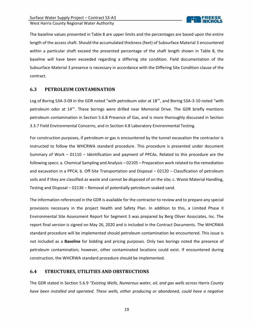
The baseline values presented in Table 8 are upper limits and the percentages are based upon the entire
length of the access shaft. Should the accumulated thickness (feet) of Subsurface Material 3 encountered
within a particular shaft exceed the presented percentage of the shaft length shown in Table 8, the
baseline will have been exceeded regarding a differing site condition. Field documentation of the
Subsurface Material 3 presence is necessary in accordance with the Differing Site Condition clause of the
contract.
6.3 PETROLEUM CONTAMINATION
Log of Boring S3A-3-09 in the GDR noted “with petroleum odor at 18’”, and Boring S3A-3-10 noted “with
petroleum odor at 14’”. These borings were drilled near Memorial Drive. The GDR briefly mentions
petroleum contamination in Section 5.6.8 Presence of Gas, and is more thoroughly discussed in Section
3.3.7 Field Environmental Concerns, and in Section 4.8 Laboratory Environmental Testing.
For construction purposes, if petroleum or gas is encountered by the tunnel excavation the contractor is
instructed to follow the WHCRWA standard procedure. This procedure is presented under document
Summary of Work – 01110 – Identification and payment of PPCAs. Related to this procedure are the
following specs: a. Chemical Sampling and Analysis – 02105 – Preparation work related to the remediation
and excavation in a PPCA; b. Off-Site Transportation and Disposal – 02120 – Classification of petroleum
soils and if they are classified as waste and cannot be disposed of on the site; c. Waste Material Handling,
Testing and Disposal – 02136 – Removal of potentially petroleum soaked sand.
The information referenced in the GDR is available for the contractor to review and to prepare any special
provisions necessary in the project Health and Safety Plan. In addition to this, a Limited Phase II
Environmental Site Assessment Report for Segment 3 was prepared by Berg Oliver Associates, Inc. The
report final version is signed on May 26, 2020 and is included in the Contract Documents. The WHCRWA
standard procedure will be implemented should petroleum contamination be encountered. This issue is
not included as a Baseline for bidding and pricing purposes. Only two borings noted the presence of
petroleum contamination; however, other contaminated locations could exist. If encountered during
construction, the WHCRWA standard procedure should be implemented.
6.4 STRUCTURES, UTILITIES AND OBSTRUCTIONS
The GDR stated in Section 5.6.9 “Existing Wells, Numerous water, oil, and gas wells across Harris County
have been installed and operated. These wells, either producing or abandoned, could have a negative

Surface Water Supply Project – Contract S3-A3 West Harris County Regional Water Authority
20
impact on groundwater, and its control during the open-cut and tunnel construction. Also, they could be
significant subsurface obstructions for the tunnel construction.”
Should a tunnel or shaft encounter an unanticipated structure, utility or obstruction the Contractor should
implement the process of notification in compliance with the Differing Site Condition Clause of the
executed contract documents.
The Contractor shall develop a tunnel work plan that will include a section describing what the Contractor
will do if an unexpected subsurface obstruction is encountered. The work plan shall describe the
procedures that will be followed or implemented if an obstruction requiring intervention is encountered.
6.5 GROUND WATER INFLOW
The tunnel access shafts will be watertight structures and tunnel excavation will be pressurized face
methods as specified in the Contract Documents. As watertight excavation methods are required for
shafts and pressurized face methods are required for tunnels, groundwater inflow into excavation has not
been baselined. The Contractor shall be responsible for collecting and removing any nuisance water from
all excavations.
6.6 FLOODING
The Contractor shall protect all excavations from flooding and is responsible for all damages, clean-up,
restoration, demobilization and remobilization associated with the project. No contract cost adjustment
will be made for flooding although contract extension time will be considered if flooding causes a delay.
6.7 APPLICATION OF BASELINES
Baselines are provided as both values and ranges. When a range of values is provided, the material
properties falling within the provided ranges are intended to be covered in the contractor bid price, while
properties falling outside that range, rather above or below the stated range, are considered as outside
the baseline range and potentially subject to differing site conditions. Tables 4 and 5 provide baseline
ranges.
When baselines are presented as single values, it is intended that the contractor bid price cover
construction activities for those material properties up to the values or the condition baselined. Tables 4
and 6 include both single values and material properties up to which the bid prices are expected to include.
Surface Water Supply Project – Contract S3-A3 West Harris County Regional Water Authority
21
The baselines are to be considered if material properties are encountered in the tunnel excavation that
are outside the baseline value(s) AND the progress of the tunnel excavation is adversely impacted.
7.0 DISCLAIMER
The provision of a baseline in the contract is not a guaranty, representation, nor a warranty or indication,
express or implied, that the baseline conditions will, in fact and actually, be encountered; rather, the
baseline is primarily intended to define, for contractual purposes, those conditions which, if determined
to be more adverse than defined, may result in an equitable adjustment of the contact price or time. The
baseline is not a guaranty or warranty that the baseline conditions actually will be encountered in the
performance of the work; nor may the contractor exclusively rely upon the baseline for the planning or
performance of any aspect of its work, including without limitation the selection, design, or
implementation of the means, methods, techniques, sequences and procedures of construction to be
employed by the contractor, and safety precautions and programs incident thereto.

Surface Water Supply Project – Contract S3-A3 West Harris County Regional Water Authority
APPENDIX A

Surface Water Supply Project – Contract S3-A3 West Harris County Regional Water Authority
Tunnelman’s Ground Classification System
(Heuer, 1974)
Classification Behavior Typical Soil Types
Firm
Heading can be advanced without initial support, and final lining can be constructed before ground starts to
move.
Loess above water table; hard clay, marl, cemented sand and gravel
when not highly overstressed
Raveling
Slow
Chunks or flakes of material begin to drop out of the arch or walls
sometime after the ground has been exposed. In fast raveling ground, the process starts within a few minutes,
otherwise the ground is slow raveling.
Residual soils or sand with small amounts of binder may be fast
raveling below the water table, slow raveling above. Stiff fissured clays
may be slow or fast raveling depending on degree of overstress.
Fast
Squeezing
Ground squeezes or extrudes plastically into tunnel, without visible fracturing or loss of continuity, and
without perceptible increase in water content. Ductile, plastic yield and flow
due to overstress.
Ground with low frictional strength. Rate of squeeze depends on degree of overstress. Occurs at shallow to
medium depth in clays of very soft to medium consistency. Stiff to hard
clay under high cover may move in combination of raveling at execution
surface and squeezing at depth behind surface.
Running
Cohesive-Running
Granular materials without cohesion are unstable at a slope greater than their angle of repose (-30° to -35°).
When exposed to steeper slopes they run like granulated sugar until the
slope flattens to the angle.
Clean, dry, granular materials. Apparent cohesion in moist sand or weak cementation in granular soil,
may allow the material to stand for a brief period of raveling before it
breaks down and runs. Such behavior is cohesive-running.
Running
Flowing
A mixture of soil and water flows into the tunnel like a viscous fluid. The material can enter the tunnel from the invert as well as from the face, crown, and walls, and can for great
distances, completely filling the tunnel in some cases.
Below the water table in silt, sand, or gravel without enough clay content
to give significant cohesion and plasticity. May also occur in highly
sensitive clay where such material is disturbed.
Swelling
Ground absorbs water, increases in volume, and expands slowly into the
tunnel.
Highly preconsolidated clay with plasticity index in excess of about 30,
generally containing significant percentages of montmorillonite.
Surface Water Supply Project – Contract S3-A3 West Harris County Regional Water Authority
APPENDIX B
Boring Logs with Tunnel Envelope

PLATE 1R:\04100\2018 Projects\0100-0199\04.10180159 - WHCRWA - F&N - Segment 3A3\000 GIS\MXD\Plate-00_Plan of Explorations.mxd, 3/26/2019, t.duran
Service Layer Credits: © 2019 Microsoft Corporation Earthstar Geographics SIOSources: Esri, HERE, Garmin, Intermap, increment P Corp., GEBCO, USGS, FAO,NPS, NRCAN, GeoBase, IGN, Kadaster NL, Ordnance Survey, Esri Japan, METI,Coordinate System: WGS 1984 Web Mercator Auxiliary SphereProjection: Mercator Auxiliary SphereDatum: WGS 1984False Easting: 0.0000False Northing: 0.0000Central Meridian: 0.0000Standard Parallel 1: 0.0000Auxiliary Sphere Type: 0.0000Units: Meter
PROJECT AREA
KEY MAPNOT TO SCALE
²0 2,000 4,0001,000
Feet
PLAN OF BORINGSSEGMENT 3A-3
WHCRWA SURFACE WATER SUPPLY PROJECT HOUSTON, TEXAS
NOTES:1. BORING LOCATIONS ARE APPROXIMATE.2. MONITORING WELL AT BORING S3A-3-09 NOT
DEVELOPED DUE TO HIGH VOC READINGS.
Northing EastingS3A-3-01 13849022 3055112 85.8 75 YesS3A-3-02 13848491 3055137 85.7 75 YesS3A-3-03 13848002 3055217 83.8 26 NoS3A-3-04 13847503 3055236 81.4 25 NoS3A-3-05 13846930 3055252 75.7 26 NoS3A-3-06 13846236 3055278 74.9 26 NoS3A-3-07 13845816 3055283 73.8 45 YesS3A-3-08 13845259 3055302 72.3 40 YesS3A-3-09 13844479 3055329 75.2 40 Yes (2)
S3A-3-10 13844323 3055334 75.1 45 NoS3A-3-11 13843314 3055354 74.9 26 NoS3A-3-12 13842275 3055389 74.1 26 NoS3A-3-13 13841634 3055305 71.4 60 YesS3A-3-14 13841267 3055343 66 60 YesS3A-3-15 13840416 3055424 71 25 No
Boring No.
State Plane Coordinates (feet) (1) Elevation
(feet) Boring Depth (feet)
Piezometer Installed
LEGENDGEOTECHNICAL BORINGMONITORING WELL
<(Ò))
Report No. 04.10180159-GDR

10
11
15
16
18
16
16
1516
20
17
14
14
17
27
22
22
19
21
26
23
22
26
19
39
38
54
59
52
52
26
4227
64
49
37
29
27
39
43
34
36
10
2711
44
32
23
118
113
110
106
104
100
112
85.684.3
71.8
57.8
47.8
43.8
FILL: ASPHALT: with crushed limestone,possibly stabilized
FILL: SILTY CLAY (CL-ML): dark gray,with brick fragments
LEAN CLAY WITH SAND (CL): very stiff,gray and tan, with calcareous nodules
- with silt pockets below 8'
FAT CLAY (CH): very stiff, red and gray,slickensided
- with silt pockets below 24'
LEAN CLAY (CL): very stiff, gray and brown
- brown below 30'
- with silty clay layers, 32' to 34'
- stiff, with silt seams below 34'
FAT CLAY (CH): very stiff, brown, with siltpockets
LEAN CLAY (CL): very stiff, brown, with siltpockets
74
98
100
97
98
98
10099
100
100
96
T
T
T
T
T
T
T
T
T
T
TSPT
SPT
T
SPT
T
T
T
T
T
T
T
25
19
14
10
20
30
40
50
: Depth To Water after 20 minutes.2. Coordinates and elevations are provided by KUO. The grid coordinates and elevations
presented are based on NAD1983 State Plane South Central and NAVD88,respectively.
3. NP: Non-plastic4. Terms and symbols defined on Plates A-16a and A-16b.
1.
HARRIS
LOG OF BORING NO. S3A-3-01
See Plate 2
PLATE A-1a
SURFACE EL.: 85.8'
NOTES:: Water First Noticed.
COORDINATES:
LOCATION:COUNTY:
13849022 N3055112 E
DATE: March 4, 2019
TOTAL DEPTH: 75'
CAVED DEPTH: 27.2'
DRY AUGER: 0' to 28'
WET ROTARY: 28' to 75'
BACKFILL: Piezometer
LOGGER: T. Mireles
DRILL RIG: ATV
SEGMENT 3A-3WHCRWA SURFACE WATER SUPPLY PROJECT
HOUSTON, TEXAS
ST
RA
TU
M
ELE
VA
TIO
N, F
T
Torvane
0.5 1.0 1.5 2.0 2.5
WA
TE
RC
ON
TE
NT
, %
R:\0
4100
\201
8 P
RO
JEC
TS
\010
0-01
99\0
4.10
1801
59
- W
HC
RW
A -
F&
N -
SE
GM
EN
T 3
A3\
000
GIS
\GIN
T\0
4.10
180
159
.GP
J
FU
GR
O S
TA
ND
AR
D L
OG
7
/12
/201
9
DE
PT
H,
FT
CLASSIFICATION SHEAR STRENGTH
Field VaneB
LOW
S P
ER
FO
OT
SA
MP
LES
WA
TE
R L
EV
EL
Penetrometer Unconfined
Miniature Vane
STRATUM DESCRIPTION% R
EC
OV
ER
Y /
RQ
D
SA
MP
LE T
YP
E
Report No. 04.10180159-GDR
UN
IT D
RY
WT
,P
CF
PA
SS
ING
NO
.20
0 S
IEV
E, %
SY
MB
OL
Triaxial
KIPS PER SQ FT
PLA
ST
ICLI
MIT
PLA
ST
ICIT
YIN
DE
X (
PI)
LIQ
UID
LIM
IT
4.1
+
+
+
+
++
+
3.4

19
NP
18
22
55
NP
36
NP
27.8
18.8
10.8
LEAN CLAY (CL): very stiff, brown, with siltpockets
FAT CLAY (CH): very stiff, brown
- brown and gray below 63'
SILTY SAND (SM): dense, brown
100
19
T
T
SPT
SPT
40
50
60
70
80
90
100
: Depth To Water after 20 minutes.2. Coordinates and elevations are provided by KUO. The grid coordinates and elevations
presented are based on NAD1983 State Plane South Central and NAVD88,respectively.
3. NP: Non-plastic4. Terms and symbols defined on Plates A-16a and A-16b.
1.
HARRIS
LOG OF BORING NO. S3A-3-01
See Plate 2
PLATE A-1b
SURFACE EL.: 85.8'
NOTES:: Water First Noticed.
COORDINATES:
LOCATION:COUNTY:
13849022 N3055112 E
DATE: March 4, 2019
TOTAL DEPTH: 75'
CAVED DEPTH: 27.2'
DRY AUGER: 0' to 28'
WET ROTARY: 28' to 75'
BACKFILL: Piezometer
LOGGER: T. Mireles
DRILL RIG: ATV
SEGMENT 3A-3WHCRWA SURFACE WATER SUPPLY PROJECT
HOUSTON, TEXAS
ST
RA
TU
M
ELE
VA
TIO
N, F
T
Torvane
0.5 1.0 1.5 2.0 2.5
WA
TE
RC
ON
TE
NT
, %
R:\0
4100
\201
8 P
RO
JEC
TS
\010
0-01
99\0
4.10
1801
59
- W
HC
RW
A -
F&
N -
SE
GM
EN
T 3
A3\
000
GIS
\GIN
T\0
4.10
180
159
.GP
J
FU
GR
O S
TA
ND
AR
D L
OG
7
/12
/201
9
DE
PT
H,
FT
CLASSIFICATION SHEAR STRENGTH
Field VaneB
LOW
S P
ER
FO
OT
SA
MP
LES
WA
TE
R L
EV
EL
Penetrometer Unconfined
Miniature Vane
STRATUM DESCRIPTION% R
EC
OV
ER
Y /
RQ
D
SA
MP
LE T
YP
E
Report No. 04.10180159-GDR
UN
IT D
RY
WT
,P
CF
PA
SS
ING
NO
.20
0 S
IEV
E, %
SY
MB
OL
Triaxial
KIPS PER SQ FT
PLA
ST
ICLI
MIT
PLA
ST
ICIT
YIN
DE
X (
PI)
LIQ
UID
LIM
IT
+
+

19
23
17
NP
NP
NP
NP
15
20
19
18
30
16
33
26
22
21
23
25
29
252425
2626
20
75
72
54
NP
NP
NP
NP
39
53
58
54
56
49
37
NP
NP
NP
NP
24
33
39
36
92
119
90
102
101
99
85.5
83.7
69.7
63.7
51.7
46.7
43.7
FILL: ASPHALT: with crushed limestoneand sand, possibly stabilized
FILL: SILTY CLAY (CL-ML): firm to stiff,gray
FAT CLAY WITH SAND (CH): stiff, brownand gray
- with silt pockets to 10' - very stiff to hard below 8'
- red and gray, slickensided below 14'
FAT CLAY (CH): stiff, red and gray,slickensided
- very stiff, with calcareous nodules below18'
POORLY GRADED SAND WITH SILT(SP-SM): medium dense, gray
- dense to very dense, brown below 26'
SILTY SAND (SM): dense, brown, with clayseams
SANDY LEAN CLAY (CL): very stiff to hard,reddish brown, with silt pockets,slickensided
FAT CLAY (CH): very stiff, red, with siltpockets, slickensided
- with calcareous nodules to 44'
82
98
99
9
10
9
13
70
99
100
100
T
T
T
T
T
T
SPT
SPT
SPT
SPT
SPT
SPT
SPT
SPT
SPT
T
T
T
T
T
T
11
11
38
50|9"
49
Ref|4"
39
47
32
10
20
30
40
50
2. Coordinates and elevations are provided by KUO. The grid coordinates and elevationspresented are based on NAD1983 State Plane South Central and NAVD88,respectively.
3. NP: Non-plastic4. Terms and symbols defined on Plates A-16a and A-16b.
1.
HARRIS
LOG OF BORING NO. S3A-3-02
See Plate 2
PLATE A-2a
SURFACE EL.: 85.7'
NOTES:: Water First Noticed.
COORDINATES:
LOCATION:COUNTY:
13848491 N3055137 E
DATE: March 1, 2019
TOTAL DEPTH: 75'
CAVED DEPTH: 20'
DRY AUGER: 0' to 22'
WET ROTARY: 22' to 75'
BACKFILL: Piezometer
LOGGER: T. Mireles
DRILL RIG: ATV
SEGMENT 3A-3WHCRWA SURFACE WATER SUPPLY PROJECT
HOUSTON, TEXAS
ST
RA
TU
M
ELE
VA
TIO
N, F
T
Torvane
0.5 1.0 1.5 2.0 2.5
WA
TE
RC
ON
TE
NT
, %
R:\0
4100
\201
8 P
RO
JEC
TS
\010
0-01
99\0
4.10
1801
59
- W
HC
RW
A -
F&
N -
SE
GM
EN
T 3
A3\
000
GIS
\GIN
T\0
4.10
180
159
.GP
J
FU
GR
O S
TA
ND
AR
D L
OG
7
/12
/201
9
DE
PT
H,
FT
CLASSIFICATION SHEAR STRENGTH
Field VaneB
LOW
S P
ER
FO
OT
SA
MP
LES
WA
TE
R L
EV
EL
Penetrometer Unconfined
Miniature Vane
STRATUM DESCRIPTION% R
EC
OV
ER
Y /
RQ
D
SA
MP
LE T
YP
E
Report No. 04.10180159-GDR
UN
IT D
RY
WT
,P
CF
PA
SS
ING
NO
.20
0 S
IEV
E, %
SY
MB
OL
Triaxial
KIPS PER SQ FT
PLA
ST
ICLI
MIT
PLA
ST
ICIT
YIN
DE
X (
PI)
LIQ
UID
LIM
IT
4.1
3.3
+
+
+
+
+
4.3

NP
14
24
18
14
NP
39
NP
25
28.7
22.2
17.7
10.7
FAT CLAY (CH): very stiff, red, with siltpockets, slickensided
SILTY SAND (SM): dense, brown
LEAN CLAY (CL): very stiff, gray andbrown, with silt pockets
SILT WITH SAND (ML): medium dense,brown and gray
35
90
83
SPT
SPT
T
SPT
45
23
29
60
70
80
90
100
2. Coordinates and elevations are provided by KUO. The grid coordinates and elevationspresented are based on NAD1983 State Plane South Central and NAVD88,respectively.
3. NP: Non-plastic4. Terms and symbols defined on Plates A-16a and A-16b.
1.
HARRIS
LOG OF BORING NO. S3A-3-02
See Plate 2
PLATE A-2b
SURFACE EL.: 85.7'
NOTES:: Water First Noticed.
COORDINATES:
LOCATION:COUNTY:
13848491 N3055137 E
DATE: March 1, 2019
TOTAL DEPTH: 75'
CAVED DEPTH: 20'
DRY AUGER: 0' to 22'
WET ROTARY: 22' to 75'
BACKFILL: Piezometer
LOGGER: T. Mireles
DRILL RIG: ATV
SEGMENT 3A-3WHCRWA SURFACE WATER SUPPLY PROJECT
HOUSTON, TEXAS
ST
RA
TU
M
ELE
VA
TIO
N, F
T
Torvane
0.5 1.0 1.5 2.0 2.5
WA
TE
RC
ON
TE
NT
, %
R:\0
4100
\201
8 P
RO
JEC
TS
\010
0-01
99\0
4.10
1801
59
- W
HC
RW
A -
F&
N -
SE
GM
EN
T 3
A3\
000
GIS
\GIN
T\0
4.10
180
159
.GP
J
FU
GR
O S
TA
ND
AR
D L
OG
7
/12
/201
9
DE
PT
H,
FT
CLASSIFICATION SHEAR STRENGTH
Field VaneB
LOW
S P
ER
FO
OT
SA
MP
LES
WA
TE
R L
EV
EL
Penetrometer Unconfined
Miniature Vane
STRATUM DESCRIPTION% R
EC
OV
ER
Y /
RQ
D
SA
MP
LE T
YP
E
Report No. 04.10180159-GDR
UN
IT D
RY
WT
,P
CF
PA
SS
ING
NO
.20
0 S
IEV
E, %
SY
MB
OL
Triaxial
KIPS PER SQ FT
PLA
ST
ICLI
MIT
PLA
ST
ICIT
YIN
DE
X (
PI)
LIQ
UID
LIM
IT

11
10
15
NP
NP
NP
NP
14
21
1819
21
20
25
25
24
19
34
38
25
NP
NP
NP
NP
23
28
10
NP
NP
NP
NP
109
106
110
67.8
59.8
57.3
49.8
32.8
28.8
FILL: SANDY LEAN CLAY (CL): stiff, gray,tan, and brown, with organic material
- very stiff below 4'
LEAN CLAY WITH SAND (CL): stiff, tanand gray, with silt pockets
CLAYEY SAND (SC): light gray
SILTY SAND (SM): loose, light gray
- medium dense below 18.5'
POORLY GRADED SAND WITH SILT(SP-SM): medium dense, light gray
LEAN CLAY (CL): very stiff, red and gray,with silt pockets, slickensided
57
76
34
14
21
7
5
9
T
T
T
T
SPT
SPT
SPT
SPT
SPT
SPT
SPT
SPT
SPT
SPT
SPT
T
10
12
11
17
29
17
11
14
15
21
*
10
20
30
40
50
: Depth To Water after 20 minutes.2. Coordinates and elevations are provided by KUO. The grid coordinates and elevations
presented are based on NAD1983 State Plane South Central and NAVD88,respectively.
3. NP: Non-plastic4. * SPT Blow counts not recorded.5. Terms and symbols defined on Plates A-16a and A-16b.
1.
HARRIS
LOG OF BORING NO. S3A-3-07
See Plate 2
PLATE A-7
SURFACE EL.: 73.8'
NOTES:: Water First Noticed.
COORDINATES:
LOCATION:COUNTY:
13845816 N3055283 E
DATE: February 26, 2019
TOTAL DEPTH: 45'
CAVED DEPTH: 15.4'
DRY AUGER: 0' to 16'
WET ROTARY: 16' to 45'
BACKFILL: Piezometer
LOGGER: T. Mireles
DRILL RIG: ATV
SEGMENT 3A-3WHCRWA SURFACE WATER SUPPLY PROJECT
HOUSTON, TEXAS
ST
RA
TU
M
ELE
VA
TIO
N, F
T
Torvane
0.5 1.0 1.5 2.0 2.5
WA
TE
RC
ON
TE
NT
, %
R:\0
4100
\201
8 P
RO
JEC
TS
\010
0-01
99\0
4.10
1801
59
- W
HC
RW
A -
F&
N -
SE
GM
EN
T 3
A3\
000
GIS
\GIN
T\0
4.10
180
159
.GP
J
FU
GR
O S
TA
ND
AR
D L
OG
7
/12
/201
9
DE
PT
H,
FT
CLASSIFICATION SHEAR STRENGTH
Field VaneB
LOW
S P
ER
FO
OT
SA
MP
LES
WA
TE
R L
EV
EL
Penetrometer Unconfined
Miniature Vane
STRATUM DESCRIPTION% R
EC
OV
ER
Y /
RQ
D
SA
MP
LE T
YP
E
Report No. 04.10180159-GDR
UN
IT D
RY
WT
,P
CF
PA
SS
ING
NO
.20
0 S
IEV
E, %
SY
MB
OL
Triaxial
KIPS PER SQ FT
PLA
ST
ICLI
MIT
PLA
ST
ICIT
YIN
DE
X (
PI)
LIQ
UID
LIM
IT

13
12
12
NP
NP
NP
NP
12
16
20
18
1617
12
16
20
24
24
25
26
50
37
16
NP
NP
NP
NP
28
47
37
25
4
NP
NP
NP
NP
16
31
106
112
110
99
71.3
65.3
59.3
56.3
38.3
36.3
32.3
FILL: SILTY CLAY (CL-ML): very stiff,gray, tan, and brown, with organic material
FAT CLAY WITH SAND (CH): stiff to verystiff, gray and brown
- with sand pockets to 2' - with calcareous nodules and ferrous
nodules below 4'LEAN CLAY WITH SAND (CL): very stiff,
gray and brown, with ferrous nodules
SILTY, CLAYEY SAND (SC-SM): dense,light gray and tan
SILTY SAND (SM): dense to very dense,light gray and tan
- with cemented sand to 26'
- brown below 20'
- with clay pockets, 30' to 32'
SANDY LEAN CLAY (CL): very stiff, brown
LEAN CLAY (CL): stiff, red, with siltpockets, slickensided
72
39
22
28
20
20
19
60
100
T
T
T
SPT
SPT
SPT
SPT
SPT
SPT
SPT
SPT
SPT
SPT
SPT
T
50
49
45
49
50|10"
40
30
50
44
50|9"
31
10
20
30
40
50
: Depth To Water after 15 minutes.2. Coordinates and elevations are provided by KUO. The grid coordinates and elevations
presented are based on NAD1983 State Plane South Central and NAVD88,respectively.
3. NP: Non-plastic4. Terms and symbols defined on Plates A-16a and A-16b.
1.
HARRIS
LOG OF BORING NO. S3A-3-08
See Plate 2
PLATE A-8
SURFACE EL.: 72.3'
NOTES:: Water First Noticed.
COORDINATES:
LOCATION:COUNTY:
13845259 N3055302 E
DATE: February 25, 2019
TOTAL DEPTH: 40'
CAVED DEPTH: 14.8'
DRY AUGER: 0' to 16'
WET ROTARY: 16' to 40'
BACKFILL: Piezometer
LOGGER: T. Mireles
DRILL RIG: ATV
SEGMENT 3A-3WHCRWA SURFACE WATER SUPPLY PROJECT
HOUSTON, TEXAS
ST
RA
TU
M
ELE
VA
TIO
N, F
T
Torvane
0.5 1.0 1.5 2.0 2.5
WA
TE
RC
ON
TE
NT
, %
R:\0
4100
\201
8 P
RO
JEC
TS
\010
0-01
99\0
4.10
1801
59
- W
HC
RW
A -
F&
N -
SE
GM
EN
T 3
A3\
000
GIS
\GIN
T\0
4.10
180
159
.GP
J
FU
GR
O S
TA
ND
AR
D L
OG
7
/12
/201
9
DE
PT
H,
FT
CLASSIFICATION SHEAR STRENGTH
Field VaneB
LOW
S P
ER
FO
OT
SA
MP
LES
WA
TE
R L
EV
EL
Penetrometer Unconfined
Miniature Vane
STRATUM DESCRIPTION% R
EC
OV
ER
Y /
RQ
D
SA
MP
LE T
YP
E
Report No. 04.10180159-GDR
UN
IT D
RY
WT
,P
CF
PA
SS
ING
NO
.20
0 S
IEV
E, %
SY
MB
OL
Triaxial
KIPS PER SQ FT
PLA
ST
ICLI
MIT
PLA
ST
ICIT
YIN
DE
X (
PI)
LIQ
UID
LIM
IT
3.0

12
12
15
NP
NP
NP
NP
NP
18
21
16
16
12
19
22
26
26
28
28
49
40
32
NP
NP
NP
NP
NP
26
37
28
17
NP
NP
NP
NP
NP
8
106
117
112
73.2
67.2
65.2
61.2
53.2
41.2
38.2
35.2
FILL: LEAN CLAY (CL): very stiff, gray andbrown, with silt pockets and organicmaterial
LEAN CLAY WITH SAND (CL): firm to stiff,gray and tan, with silt pockets
SANDY LEAN CLAY (CL): stiff to very stiff,gray and tan, with calcareous nodules
CLAYEY SAND (SC): gray and brown, withcalcareous nodules
- with silt pockets below 12'
SILTY SAND (SM): medium dense, lightgray, with cemented sand
- with petroleum odor at 18'
POORLY GRADED SAND WITH SILT(SP-SM): medium dense, gray
- brown, 30' to 34'
- loose below 32.5'
SILTY SAND (SM): medium dense, red andbrown, with clay pockets
LEAN CLAY (CL): soft, red, with siltpockets
73
52
45
31
16
9
5
5
19
97
T
T
T
T
T
SPT
SPT
SPT
SPT
SPT
SPT
SPT
SPT
SPT
SPT
SPT
SPT
26
14
22
18
15
21
22
17
17
9
14
3
10
20
30
40
50
2. Coordinates and elevations are provided by KUO. The grid coordinates and elevationspresented are based on NAD1983 State Plane South Central and NAVD88,respectively.
3. NP: Non-plastic / * Piezometer not developed due to high VOC readings measured onsoil samples. See text for details.
5. Terms and symbols defined on Plates A-16a and A-16b.
1.
HARRIS
LOG OF BORING NO. S3A-3-09
See Plate 2
PLATE A-9
SURFACE EL.: 75.2'
NOTES:: Water First Noticed.
COORDINATES:
LOCATION:COUNTY:
13844479 N3055329 E
DATE: February 22, 2019
TOTAL DEPTH: 40'
CAVED DEPTH: 14.4'
DRY AUGER: 0' to 20'
WET ROTARY: 20' to 40'
BACKFILL: Piezometer *
LOGGER: T. Mireles
DRILL RIG: ATV
SEGMENT 3A-3WHCRWA SURFACE WATER SUPPLY PROJECT
HOUSTON, TEXAS
ST
RA
TU
M
ELE
VA
TIO
N, F
T
Torvane
0.5 1.0 1.5 2.0 2.5
WA
TE
RC
ON
TE
NT
, %
R:\0
4100
\201
8 P
RO
JEC
TS
\010
0-01
99\0
4.10
1801
59
- W
HC
RW
A -
F&
N -
SE
GM
EN
T 3
A3\
000
GIS
\GIN
T\0
4.10
180
159
.GP
J
FU
GR
O S
TA
ND
AR
D L
OG
7
/12
/201
9
DE
PT
H,
FT
CLASSIFICATION SHEAR STRENGTH
Field VaneB
LOW
S P
ER
FO
OT
SA
MP
LES
WA
TE
R L
EV
EL
Penetrometer Unconfined
Miniature Vane
STRATUM DESCRIPTION% R
EC
OV
ER
Y /
RQ
D
SA
MP
LE T
YP
E
Report No. 04.10180159-GDR
UN
IT D
RY
WT
,P
CF
PA
SS
ING
NO
.20
0 S
IEV
E, %
SY
MB
OL
Triaxial
KIPS PER SQ FT
PLA
ST
ICLI
MIT
PLA
ST
ICIT
YIN
DE
X (
PI)
LIQ
UID
LIM
IT

11
12
12
15
NP
NP
NP
NP
NP
20
17
16
11
18
22
20
24
22
26
40
46
43
24
NP
NP
NP
NP
NP
29
34
31
9
NP
NP
NP
NP
NP
106
115
110
73.1
67.1
61.1
56.6
52.6
43.1
34.1
30.1
FILL: SILTY CLAY (CL-ML): dark gray
LEAN CLAY WITH SAND (CL): stiff, darkgray
- with organic material to 5'
SANDY LEAN CLAY (CL): very stiff, grayand brown
- with ferrous nodules, slickensided to 12' - with silt pockets below 10' - stiff to very stiff, gray below 12'
CLAYEY SAND (SC): medium dense, gray - with petroleum odor at 14'
SILTY SAND (SM): medium dense, gray
POORLY GRADED SAND WITH SILT(SP-SM): medium dense, gray
SILTY SAND (SM): medium dense, brownand gray
- dense to very dense below 38'
LEAN CLAY (CL): very stiff, red and gray,with silt pockets and seams, slickensided
78
68
53
19
20
10
11
17
T
T
T
T
T
SPT
SPT
SPT
SPT
SPT
SPT
SPT
SPT
SPT
SPT
SPT
T
15
14
12
16
24
25
15
20
25
26
50
10
20
30
40
50
2. Coordinates and elevations are provided by KUO. The grid coordinates and elevationspresented are based on NAD1983 State Plane South Central and NAVD88,respectively.
3. NP: Non-plastic4. Terms and symbols defined on Plates A-16a and A-16b.
1.
HARRIS
LOG OF BORING NO. S3A-3-10
See Plate 2
PLATE A-10
SURFACE EL.: 75.1'
NOTES:: Water First Noticed.
COORDINATES:
LOCATION:COUNTY:
13844323 N3055334 E
DATE: February 20, 2019
TOTAL DEPTH: 45'
CAVED DEPTH: 19.7'
DRY AUGER: 0' to 24'
WET ROTARY: 24' to 45'
BACKFILL: Cement-Bentonite Grout
LOGGER: T. Mireles
DRILL RIG: ATV
SEGMENT 3A-3WHCRWA SURFACE WATER SUPPLY PROJECT
HOUSTON, TEXAS
ST
RA
TU
M
ELE
VA
TIO
N, F
T
Torvane
0.5 1.0 1.5 2.0 2.5
WA
TE
RC
ON
TE
NT
, %
R:\0
4100
\201
8 P
RO
JEC
TS
\010
0-01
99\0
4.10
1801
59
- W
HC
RW
A -
F&
N -
SE
GM
EN
T 3
A3\
000
GIS
\GIN
T\0
4.10
180
159
.GP
J
FU
GR
O S
TA
ND
AR
D L
OG
7
/12
/201
9
DE
PT
H,
FT
CLASSIFICATION SHEAR STRENGTH
Field VaneB
LOW
S P
ER
FO
OT
SA
MP
LES
WA
TE
R L
EV
EL
Penetrometer Unconfined
Miniature Vane
STRATUM DESCRIPTION% R
EC
OV
ER
Y /
RQ
D
SA
MP
LE T
YP
E
Report No. 04.10180159-GDR
UN
IT D
RY
WT
,P
CF
PA
SS
ING
NO
.20
0 S
IEV
E, %
SY
MB
OL
Triaxial
KIPS PER SQ FT
PLA
ST
ICLI
MIT
PLA
ST
ICIT
YIN
DE
X (
PI)
LIQ
UID
LIM
IT
+3.3
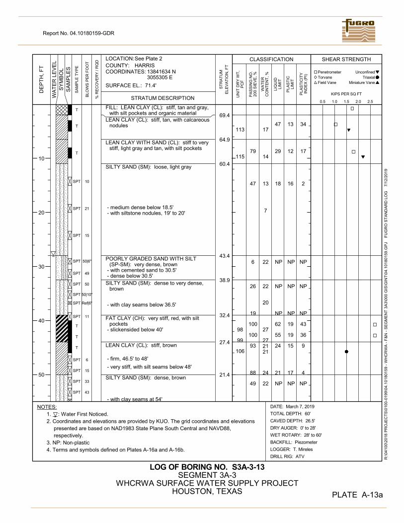
13
12
16
NP
NP
NP
19
19
15
17
NP
17
14
13
7
22
22
20
27
272121
24
22
47
29
18
NP
NP
NP
62
55
24
21
NP
34
17
2
NP
NP
NP
43
36
9
4
NP
113
115
98
99
106
69.4
64.9
60.4
43.4
38.9
32.4
27.4
21.4
FILL: LEAN CLAY (CL): stiff, tan and gray,with silt pockets and organic material
LEAN CLAY (CL): stiff, tan, with calcareousnodules
LEAN CLAY WITH SAND (CL): stiff to verystiff, light gray and tan, with silt pockets
SILTY SAND (SM): loose, light gray
- medium dense below 18.5'- with siltstone nodules, 19' to 20'
POORLY GRADED SAND WITH SILT(SP-SM): very dense, brown
- with cemented sand to 30.5'- dense below 30.5'
SILTY SAND (SM): dense to very dense,brown
- with clay seams below 36.5'
FAT CLAY (CH): very stiff, red, with siltpockets
- slickensided below 40'
LEAN CLAY (CL): stiff, brown
- firm, 46.5' to 48'
- very stiff, with silt seams below 48'
SILTY SAND (SM): dense, brown
- with clay seams at 54'
79
47
6
26
19
100
100
93
88
49
T
T
T
SPT
SPT
SPT
SPT
SPT
SPT
SPT
SPT
SPT
T
T
T
SPT
SPT
SPT
SPT
10
21
15
50|6"
49
50
50|10"
Ref|6"
11
6
15
33
43
10
20
30
40
50
2. Coordinates and elevations are provided by KUO. The grid coordinates and elevationspresented are based on NAD1983 State Plane South Central and NAVD88,respectively.
3. NP: Non-plastic4. Terms and symbols defined on Plates A-16a and A-16b.
1.
HARRIS
LOG OF BORING NO. S3A-3-13
See Plate 2
PLATE A-13a
SURFACE EL.: 71.4'
NOTES:: Water First Noticed.
COORDINATES:
LOCATION:COUNTY:
13841634 N3055305 E
DATE: March 7, 2019
TOTAL DEPTH: 60'
CAVED DEPTH: 26.5'
DRY AUGER: 0' to 28'
WET ROTARY: 28' to 60'
BACKFILL: Piezometer
LOGGER: T. Mireles
DRILL RIG: ATV
SEGMENT 3A-3WHCRWA SURFACE WATER SUPPLY PROJECT
HOUSTON, TEXAS
ST
RA
TU
M
ELE
VA
TIO
N, F
T
Torvane
0.5 1.0 1.5 2.0 2.5
WA
TE
RC
ON
TE
NT
, %
R:\0
4100
\201
8 P
RO
JEC
TS
\010
0-01
99\0
4.10
1801
59
- W
HC
RW
A -
F&
N -
SE
GM
EN
T 3
A3\
000
GIS
\GIN
T\0
4.10
180
159
.GP
J
FU
GR
O S
TA
ND
AR
D L
OG
7
/12
/201
9
DE
PT
H,
FT
CLASSIFICATION SHEAR STRENGTH
Field VaneB
LOW
S P
ER
FO
OT
SA
MP
LES
WA
TE
R L
EV
EL
Penetrometer Unconfined
Miniature Vane
STRATUM DESCRIPTION% R
EC
OV
ER
Y /
RQ
D
SA
MP
LE T
YP
E
Report No. 04.10180159-GDR
UN
IT D
RY
WT
,P
CF
PA
SS
ING
NO
.20
0 S
IEV
E, %
SY
MB
OL
Triaxial
KIPS PER SQ FT
PLA
ST
ICLI
MIT
PLA
ST
ICIT
YIN
DE
X (
PI)
LIQ
UID
LIM
IT

NP
21
23
32
NP
67
NP
46
16.4
12.411.4
SANDY SILT (ML): dense, brown
FAT CLAY (CH): very stiff, red,slickensided
51
99
SPTSPT
SPT
3535
1760
70
80
90
100
2. Coordinates and elevations are provided by KUO. The grid coordinates and elevationspresented are based on NAD1983 State Plane South Central and NAVD88,respectively.
3. NP: Non-plastic4. Terms and symbols defined on Plates A-16a and A-16b.
1.
HARRIS
LOG OF BORING NO. S3A-3-13
See Plate 2
PLATE A-13b
SURFACE EL.: 71.4'
NOTES:: Water First Noticed.
COORDINATES:
LOCATION:COUNTY:
13841634 N3055305 E
DATE: March 7, 2019
TOTAL DEPTH: 60'
CAVED DEPTH: 26.5'
DRY AUGER: 0' to 28'
WET ROTARY: 28' to 60'
BACKFILL: Piezometer
LOGGER: T. Mireles
DRILL RIG: ATV
SEGMENT 3A-3WHCRWA SURFACE WATER SUPPLY PROJECT
HOUSTON, TEXAS
ST
RA
TU
M
ELE
VA
TIO
N, F
T
Torvane
0.5 1.0 1.5 2.0 2.5
WA
TE
RC
ON
TE
NT
, %
R:\0
4100
\201
8 P
RO
JEC
TS
\010
0-01
99\0
4.10
1801
59
- W
HC
RW
A -
F&
N -
SE
GM
EN
T 3
A3\
000
GIS
\GIN
T\0
4.10
180
159
.GP
J
FU
GR
O S
TA
ND
AR
D L
OG
7
/12
/201
9
DE
PT
H,
FT
CLASSIFICATION SHEAR STRENGTH
Field VaneB
LOW
S P
ER
FO
OT
SA
MP
LES
WA
TE
R L
EV
EL
Penetrometer Unconfined
Miniature Vane
STRATUM DESCRIPTION% R
EC
OV
ER
Y /
RQ
D
SA
MP
LE T
YP
E
Report No. 04.10180159-GDR
UN
IT D
RY
WT
,P
CF
PA
SS
ING
NO
.20
0 S
IEV
E, %
SY
MB
OL
Triaxial
KIPS PER SQ FT
PLA
ST
ICLI
MIT
PLA
ST
ICIT
YIN
DE
X (
PI)
LIQ
UID
LIM
IT

12
16
14
11
12
18
18
19
16
17
15
14
15
15
21
20
26
2728
25
2723
23
23
25
18
18
21
19
34
57
55
62
28
49
28
31
6
2
7
8
22
39
37
43
12
32
13
17
97
99105
103
58.0
48.0
44.0
35.5
33.0
23.0
14.0
SILTY, CLAYEY SAND (SC-SM): loose,brown
- brown and gray below 3'
SANDY SILT (ML): loose, brown
- with silty clay streaks below 16'
SILTY CLAY WITH SAND (CL-ML): brown
CLAYEY SAND (SC): very loose, gray andbrown
LEAN CLAY WITH SAND (CL): very stiff,gray and brown
FAT CLAY (CH): stiff to very stiff, red andgray, slickensided
- with silt pockets to 36' - very stiff below 36'
LEAN CLAY (CL): very stiff, red and gray,with clayey silt layers
LEAN CLAY WITH SAND (CL): brown
- stiff below 54.5'
44
60
72
35
75
100
100
99
98
100
82
SPT
SPT
SPT
T
SPT
SPT
T
T
T
T
T
T
T
T
T
T
T
4
4
5
3
20
10
20
30
40
50
2. Coordinates and elevations are provided by KUO. The grid coordinates and elevationspresented are based on NAD1983 State Plane South Central and NAVD88,respectively.
3. Terms and symbols defined on Plates A-16a and A-16b.
1.
HARRIS
LOG OF BORING NO. S3A-3-14
See Plate 2
PLATE A-14a
SURFACE EL.: 66.0'
NOTES:: Water First Noticed.
COORDINATES:
LOCATION:COUNTY:
13841267 N3055343 E
DATE: March 11, 2019
TOTAL DEPTH: 60'
CAVED DEPTH: 18.7'
DRY AUGER: 0' to 25'
WET ROTARY: 25' to 60'
BACKFILL: Piezometer
LOGGER: T. Mireles
DRILL RIG: ATV
SEGMENT 3A-3WHCRWA SURFACE WATER SUPPLY PROJECT
HOUSTON, TEXAS
ST
RA
TU
M
ELE
VA
TIO
N, F
T
Torvane
0.5 1.0 1.5 2.0 2.5
WA
TE
RC
ON
TE
NT
, %
R:\0
4100
\201
8 P
RO
JEC
TS
\010
0-01
99\0
4.10
1801
59
- W
HC
RW
A -
F&
N -
SE
GM
EN
T 3
A3\
000
GIS
\GIN
T\0
4.10
180
159
.GP
J
FU
GR
O S
TA
ND
AR
D L
OG
7
/12
/201
9
DE
PT
H,
FT
CLASSIFICATION SHEAR STRENGTH
Field VaneB
LOW
S P
ER
FO
OT
SA
MP
LES
WA
TE
R L
EV
EL
Penetrometer Unconfined
Miniature Vane
STRATUM DESCRIPTION% R
EC
OV
ER
Y /
RQ
D
SA
MP
LE T
YP
E
Report No. 04.10180159-GDR
UN
IT D
RY
WT
,P
CF
PA
SS
ING
NO
.20
0 S
IEV
E, %
SY
MB
OL
Triaxial
KIPS PER SQ FT
PLA
ST
ICLI
MIT
PLA
ST
ICIT
YIN
DE
X (
PI)
LIQ
UID
LIM
IT
3.6
+

1623 53 37
9.0
6.0
LEAN CLAY WITH SAND (CL): stiff, brown
FAT CLAY (CH): very stiff, gray and brown,slickensided 98
SPTSPT
T
1313
60
70
80
90
100
2. Coordinates and elevations are provided by KUO. The grid coordinates and elevationspresented are based on NAD1983 State Plane South Central and NAVD88,respectively.
3. Terms and symbols defined on Plates A-16a and A-16b.
1.
HARRIS
LOG OF BORING NO. S3A-3-14
See Plate 2
PLATE A-14b
SURFACE EL.: 66.0'
NOTES:: Water First Noticed.
COORDINATES:
LOCATION:COUNTY:
13841267 N3055343 E
DATE: March 11, 2019
TOTAL DEPTH: 60'
CAVED DEPTH: 18.7'
DRY AUGER: 0' to 25'
WET ROTARY: 25' to 60'
BACKFILL: Piezometer
LOGGER: T. Mireles
DRILL RIG: ATV
SEGMENT 3A-3WHCRWA SURFACE WATER SUPPLY PROJECT
HOUSTON, TEXAS
ST
RA
TU
M
ELE
VA
TIO
N, F
T
Torvane
0.5 1.0 1.5 2.0 2.5
WA
TE
RC
ON
TE
NT
, %
R:\0
4100
\201
8 P
RO
JEC
TS
\010
0-01
99\0
4.10
1801
59
- W
HC
RW
A -
F&
N -
SE
GM
EN
T 3
A3\
000
GIS
\GIN
T\0
4.10
180
159
.GP
J
FU
GR
O S
TA
ND
AR
D L
OG
7
/12
/201
9
DE
PT
H,
FT
CLASSIFICATION SHEAR STRENGTH
Field VaneB
LOW
S P
ER
FO
OT
SA
MP
LES
WA
TE
R L
EV
EL
Penetrometer Unconfined
Miniature Vane
STRATUM DESCRIPTION% R
EC
OV
ER
Y /
RQ
D
SA
MP
LE T
YP
E
Report No. 04.10180159-GDR
UN
IT D
RY
WT
,P
CF
PA
SS
ING
NO
.20
0 S
IEV
E, %
SY
MB
OL
Triaxial
KIPS PER SQ FT
PLA
ST
ICLI
MIT
PLA
ST
ICIT
YIN
DE
X (
PI)
LIQ
UID
LIM
IT

10
10
8
10
NP
11
11
20
14
11
6
21
38
39
35
23
NP
28
29
27
13
NP
121
110
117
69.0
59.0
56.0
53.0
46.0
FILL: SILTY CLAY (CL-ML): stiff, gray andbrown, with shell fragments and limestonefragments
LEAN CLAY WITH SAND (CL): very stiff tohard, gray, with silt pockets
- very stiff, gray and tan, calcareousnodules, and ferrous nodules below 6'
- tan and gray below 8'
SANDY LEAN CLAY (CL): very stiff, brownand gray, with silt pockets, calcareousnodules, and ferrous nodules
- stiff below 14'CLAYEY SAND (SC): medium dense, light
gray, with clay streaksPOORLY GRADED SAND WITH SILT
(SP-SM): medium dense, gray
- loose, 22' to 23.5'- brown below 22'- medium dense below 22'
76
82
66
48
10
9
T
T
T
T
T
T
T
SPT
SPT
SPT
SPT
SPT
13
14
12
9
20
10
20
30
40
50
: Depth To Water after 45 minutes.2. Coordinates and elevations are provided by KUO. The grid coordinates and elevations
presented are based on NAD1983 State Plane South Central and NAVD88,respectively.
3. NP: Non-plastic4. Terms and symbols defined on Plates A-16a and A-16b.
1.
HARRIS
LOG OF BORING NO. S3A-3-15
See Plate 2
PLATE A-15
SURFACE EL.: 71.0'
NOTES:: Water First Noticed.
COORDINATES:
LOCATION:COUNTY:
13840416 N3055424 E
DATE: March 11, 2019
TOTAL DEPTH: 25'
CAVED DEPTH: 22.4'
DRY AUGER: 0' to 23.5'
WET ROTARY: 23.5' to 25'
BACKFILL: Cement-Bentonite Grout
LOGGER: T. Mireles
DRILL RIG: ATV
SEGMENT 3A-3WHCRWA SURFACE WATER SUPPLY PROJECT
HOUSTON, TEXAS
ST
RA
TU
M
ELE
VA
TIO
N, F
T
Torvane
0.5 1.0 1.5 2.0 2.5
WA
TE
RC
ON
TE
NT
, %
R:\0
4100
\201
8 P
RO
JEC
TS
\010
0-01
99\0
4.10
1801
59
- W
HC
RW
A -
F&
N -
SE
GM
EN
T 3
A3\
000
GIS
\GIN
T\0
4.10
180
159
.GP
J
FU
GR
O S
TA
ND
AR
D L
OG
7
/12
/201
9
DE
PT
H,
FT
CLASSIFICATION SHEAR STRENGTH
Field VaneB
LOW
S P
ER
FO
OT
SA
MP
LES
WA
TE
R L
EV
EL
Penetrometer Unconfined
Miniature Vane
STRATUM DESCRIPTION% R
EC
OV
ER
Y /
RQ
D
SA
MP
LE T
YP
E
Report No. 04.10180159-GDR
UN
IT D
RY
WT
,P
CF
PA
SS
ING
NO
.20
0 S
IEV
E, %
SY
MB
OL
Triaxial
KIPS PER SQ FT
PLA
ST
ICLI
MIT
PLA
ST
ICIT
YIN
DE
X (
PI)
LIQ
UID
LIM
IT
+
+
+10.7
3.1

Program Manager
TO ARRANGE FOR LINES TO BE TURNED OFF OR MOVED. CALL CENTERPOINTENERGY AT 713-207-2222
NOTICE:For your safety, you are required by Texas Law to call 811 at least 48 hours before you dig
call 811.
VERIFICATION OF PRIVATE UTILITY LINES
Date:CenterPoint Energy/Natural Gas Facilities Verification ONLY.(This Signature verifies that you have shown CNP Natural Gas Lines correctly - not to beused for conflict verification.)Signature Valid for six months.
(Gas service lines are not shown.)
Date:CenterPoint Energy/UNDERGROUND Electrical Facilities Verification ONLY.(This Signature verifies existing underground facilities - not to be used for conflict verification.)Signature Valid for six months.
Date:
PHONE: 281.994.7993
SEGMENT C
GEOTECHNICAL INSTRUMENTATIONDETAILS
SHEET 1 OF 2
NA
NA
TU-017389
3'
2'-6
"
NOTES:
1. REFLECTIVE MONITORING POINT SHALL BE CONSIDERED OF PLASTIC, SHAPED TO BE FLUSH ORPERPENDICULARLY PROTRUDE FROM THE SURFACE TO WHICH IT IS AFFIXED, AND WILL BEAFFIXED TO MONITOR ELEMENTS BY EPOXY OR REMOVABLE ANCHOR, WHICHEVER ISAPPROPRIATE.
2. REFLECTIVE MONITORING POINTS SHALL BE MODEL RS90 OR RSZ-10-30x30mm RETROREFLECTIVE SURVEY TARGETS, MANUFACTURED BY BERNSTEN OR SIMILAR. IF REFLECTIVEMONITORING POINT CAN NOT BE ANCHORED BY EPOXY, SUFFICIENT ANCHORAGE SHOULD BEUSED TO INSTALL THE REFLECTIVE MONITORING POINT TO PROVIDE FOR POSITIVE ANCHORAGETHROUGHOUT THE ANTICIPATED MONITORING PERIOD.
ADHESIVE TARGET
~1.0xD SPACING ASSHOWN ONDRAWINGS
D
TUNNEL℄
NOTES:1. DRIVE REBAR OR DRILL AND GROUT EMBEDMENT TO ACHIEVE FIRM
ANCHORAGE.
2. IF ONLY VERTICAL MONITORING IS REQUIRED, PROVIDE CENTERMARK ON TOP OF REBAR TO ACCEPT SURVEY ROD.
12 IN
MIN
. EM
BEDM
ENT
12 IN
1.5
INM
IN
1.5
INM
IN
NOTES:1. CONTRACTOR MAY INSTALL BY EITHER METHOD, DEPENDING ON PAVEMENT MATERIAL.
NOTES:1. FOR SURFACE OTHER THAN CONCRETE, BRICK OR MASONRY, EPOXY TO SURFACE.
2. ANCHOR INTO SOUND CONCRETE ENCASEMENT OR INTO STEEL MEMBERS. ATBUILDING FACADES ANCHOR INTO STRUCTURAL ELEMENTS.
3. SURFACE SURVEY POINTS SHALL BE INSTALLED 3 TO 5 FT. ABOVE GRADE.
CONTRACT S3-A3Engineer of Record
Texas Registered Engineering Firm F-#2144
Program ManagerDANNENBAUMENGINEERING CORPORATION
5-
4-
GROUNDSURFACE
MONITORING POINTS(GMP, SMP, OR RMP'S)
1-
RS90
NO. 5 REBAR(SEE NOTE 1)
4" PVC CASING
CEMENT GROUT BACKFILL
GROUND SURFACE
ROADWAY BOX WITHBOLTED TRAFFIC CAP
IDENTIFICATION MARKER FIRMLYATTACHED TO REBAR OR CASING
PK NAILSURVEY WASHER WITHPOINT IDENTIFICATION
SEE DETAIL "2A"PK NAIL
DRILL HOLE
EPOXY RESIN
2A-
2-
LEAD WEDGE NUT
SLEEVECONCRETE, BRICK ORMASONRY SURFACE
2" LONG X 1/2" Ø SS HEXEXPANSION ANCHORPOSITIONED WITH POINT UPTO RECEIVE SURVEY ROD.
1/2" Ø HOLE DRILLED INMASONRY OR CONCRETE
3-
RSZ2-10-30x30mmRETRO REFLECTIVESURVEY TARGETS WITHADHESIVE BACKING
GEOTECHNICAL INSTRUMENTATIONDETAILS SHEET I
NTS
NTSTU-012
14-
09-2
021
NO
TE
1
CEQ