Embed Size (px)
Citation preview

SPIE 4343-100
1
Adding static printing capabilities to the EUV phase-shiftingpoint diffraction interferometer
Patrick Naulleau1, Kenneth A. Goldberg1, Erik H. Anderson1, Philli p Batson1,Paul Denham1, Keith Jackson1, Seno Rekawa1, and Jeff rey Bokor1,2
1Center for X-Ray Optics, Lawrence Berkeley National Laboratory, Berkeley, CA 947202EECS Department, University of Cali fornia, Berkeley, CA 94720
ABSTRACT
While interferometry is routinely used for the characterization and alignment of lithographicoptics, the ultimate performance metric for these optics is printing in photoresist. Directcomparison of imaging and wavefront performance is also useful for verifying and improving thepredictive power of wavefront metrology under actual printing conditions. To address theseissues, static, small-field printing capabilities are being added to the extreme ultraviolet (EUV)phase-shifting point diffraction interferometer (PS/PDI) implemented at the Advanced LightSource at Lawrence Berkeley National Laboratory. This Sub-field Exposure Station (SES) willenable the earliest possible imaging characterization of the upcoming Engineering Test Stand(ETS) Set-2 projection optics.
Relevant printing studies with the ETS projection optics require illumination partialcoherence with σ of approximately 0.7. This σ value is very different from the coherentillumination requirements of the EUV PS/PDI and the coherence properties naturally provided bysynchrotron undulator beamline illumination. Adding printing capabilities to the PS/PDIexperimental system thus necessitates the development of an alternative illumination systemcapable of destroying the inherent coherence of the beamline. The SES is being implementedwith two independent illuminators: the first is based on a novel EUV diffuser currently underdevelopment and the second is based on a scanning mirror design.
Here we describe the design and implementation of the new SES, including a discussion ofthe illuminators and the fabrication of the EUV diffuser.
Keywords: extreme ultraviolet lithography, synchrotron radiation, microfield printing, EUVdiffuser, decoherentizing ill uminator
1. INTRODUCTION
The semiconductor industry’s push towards ever-smaller circuit feature sizes has led to acontinual shortening of the wavelength used in the lithography step. Historically, lithographysystems used in mass production have been based on refractive projection optical systems.However, continuation of the wavelength-shortening trend and the unavailability of transparentrefractive materials for shorter wavelengths will eventually lead to a departure from refractivesystems. One of the most promising so-called next-generation lithography systems is extremeultraviolet (EUV) projection lithography, in which multilayer-coated mirrors are used to formcompound projection optics operating in the 13- to 14-nm wavelength range. Achievinglithographic-quality, diffraction-limited performance requires that the projection optics have rmswavefront quality on the order of λ/50 (0.27 nm at λ = 13.4 nm).1 Because EUV systems utilizeresonant reflective coatings,2 at-wavelength characterization3 is critical to the developmentprocess.

SPIE 4343-100
2
In order to meet the at-wavelength wavefront metrology challenge, an EUV-compatiblediffraction-class interferometer, the phase-shifting point diffraction interferometer (PS/PDI), wasdeveloped by Medecki et al.4 The PS/PDI is a common-path, system-level interferometer thatrelies on pinhole diffraction to generate both the illumination and reference beams. A diffractiongrating is used as the beam-splitting and phase-shifting element. The PS/PDI has recently beendemonstrated to have a reference wavefront accuracy of better than λEUV/350 (0.4 Å) within anumerical aperture (NA) of 0.082.5
The EUV PS/PDI, implemented at Lawrence Berkeley National Laboratory’s AdvancedLight Source synchrotron radiation facility, has been in operation for several years and isroutinely used to characterize EUV lithographic optics.6-8 Two separate EUV PS/PDIinterferometers have been constructed: the first was designed to test the 10×-reduction EUVSchwarzschild cameras9 used in the Microsteppers10 installed at Sandia National Laboratorieswhereas the second, much larger scale interferometer, was designed to test the 4×-reductionprojection optics box11 designed at Lawrence Livermore National Laboratory and used in theEUV Engineering Test Stand (ETS)12 now operational at the Virtual National Laboratory (theVirtual National Laboratory is a partnership between Lawrence Berkley, Lawrence Livermore,and Sandia National Laboratories).
While wavefront interferometry is routinely used for the characterization and alignment oflithographic optics, the ultimate performance metric is printing in photoresist. Direct comparisonof imaging and wavefront performance is also useful for verifying and improving the predictivepower of wavefront metrology under actual printing conditions. To address these issues, static,small-field printing capabili ties are being added to the EUV PS/PDI designed to characterize ETSprojection optics. Although the ultimate destination for these optics remains integration into theETS for full-field scanned imaging, valuable early learning can be obtained by the new small-field static printing capabili ties of the enhanced PS/PDI endstation. This Sub-field ExposureStation (SES) will enable the earliest possible imaging characterization of the ETS set-2projection optics (undergoing final assembly as of the writing of this manuscript, February,2001).
A static imaging system, the SES will have a subfield size of approximately 100 µm at thewafer. However, the full 1-inch arc field can be covered one subfield at a time by moving theentire system relative to the stationary illumination beam as is done in the interferometry.13 TheSES wil l work with essentially the same reflection masks as used in the ETS. In addition, the SESwill support variable partial coherence (σ) ranging from approximately 0.2 to 1.
The biggest challenge for the implementation of printing capabilities at the EUVinterferometry beamline is illumination coherence. Relevant printing studies with the ETSprojection optics require illumination partial coherence (σ) of approximately 0.7. This σ value isvery different from the coherent illumination requirements of the EUV PS/PDI and the coherenceproperties naturally provided by synchrotron undulator beamline il lumination.14,15 Adding printingcapabilities to the PS/PDI experimental system thus necessitates the development of analternative illumination system capable of destroying the inherent coherence of the beamline. TheSES is being implemented with two independent illuminators: the first is based on a novel EUVdiffuser currently under development and the second is based on a scanning mirror design.
2. ADDING PRINTING CAPABILITIES TO THE PS/PDI
Although the illumination issue is the most fundamental of the changes required toimplement printing in the EUV interferometry tool, several other modifications are necessary. Inthis section we summarize these modifications; the illumination is specifically addressed in thenext section.
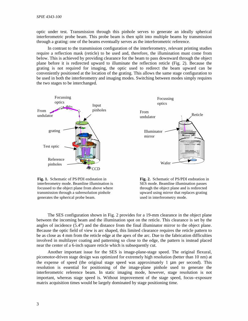
By design, the PS/PDI (Fig. 1) is a transmission device. The beamline il lumination comesfrom above where it is focussed onto a subresolution pinhole in the object (reticle) plane of the
SPIE 4343-100
3
optic under test. Transmission through this pinhole serves to generate an ideally sphericalinterferometric probe beam. This probe beam is then split into multiple beams by transmissionthrough a grating: one of the beams eventually serves as the interferometric reference.
In contrast to the transmission configuration of the interferometry, relevant printing studiesrequire a reflection mask (reticle) to be used and, therefore, the illumination must come frombelow. This is achieved by providing clearance for the beam to pass downward through the objectplane before it is redirected upward to illuminate the reflection reticle (Fig. 2). Because thegrating is not required for imaging, the optic used to redirect the beam upward can beconveniently positioned at the location of the grating. This allows the same stage configuration tobe used in both the interferometry and imaging modes. Switching between modes simply requiresthe two stages to be interchanged.
The SES configuration shown in Fig. 2 provides for a 19-mm clearance in the object planebetween the incoming beam and the illumination spot on the reticle. This clearance is set by theangles of incidence (5.4°) and the distance from the final i lluminator mirror to the object plane.Because the optic field of view is arc shaped, this limited clearance requires the reticle pattern tobe as close as 4 mm from the reticle edge at the apex of the arc. Due to the fabrication difficultiesinvolved in multilayer coating and patterning so close to the edge, the pattern is instead placednear the center of a 6-inch square reticle which is subsequently cut.
Another important issue for the SES is image-plane-stage speed. The original flexural,picomotor-driven stage design was optimized for extremely high resolution (better than 10 nm) atthe expense of speed (the original stage speed was approximately 1 µm per second). Thisresolution is essential for positioning of the image-plane pinhole used to generate theinterferometric reference beam. In static imaging mode, however, stage resolution is notimportant, whereas stage speed is. Without improvement of the stage speed, focus–exposurematrix acquisition times would be largely dominated by stage positioning time.
Fig. 1. Schematic of PS/PDI endstation ininterferometry mode. Beamline illumination isfocussed to the object plane from above wheretransmission through a subresolution pinholegenerates the spherical probe beam.
grating
Fromundulator
Focussingoptics
Inputpinholes
Referencepinholes
CCD
Test optic
Illuminatormirror
Fromundulator
Focussingoptics
Reticle
Wafer
Fig. 2. Schematic of PS/PDI endstation inSES mode. Beamline illumination passesthrough the object plane and is redirectedupward using mirror that replaces gratingused in interferometry mode.

SPIE 4343-100
4
To address the lateral-scanning speed issue anested-stage solution has been implemented (Fig. 3).The entire picomotor drive assembly is now separatelydriven by a much faster, optical-positioning DC-servomotor providing an approximately 20× increase instage speed. This nested design allows the same stageto be used in both interferometry and printing modes,facilitating the transition between the two modes.
The new image-plane stage is also equippedwith an electrostatic chuck to hold the imaging wafersflat. In orer to accommodate interferometry, the chuckhas an open slot in the area of the static field throughwhich the interferometric beams pass to the CCD.
The other major mechanical upgrade for printingfunctionality is the addition of a vacuum load-lockwafer-transfer system for the image-plane stage. This custom-designed system enables rapidtransfer of imaging wafers and provides adequate positioning accuracy for the pinhole wafersused in interferometry mode.
3. ILLUMINATORS
As stated above, two illumination systems are being implemented for the SES. The first isbased on a novel EUV diffuser currently under development. Although encouraging progress hasbeen made in the development of this diffuser, a final device of acceptable efficiency has yet tobe fabricated. Thus, we have concurrently developed a second illuminator based on a scanningmirror design. The two illuminators can be implemented in parallel, and switching from one tothe other is relatively trivial.
The diffuser-based illuminator was particularlyattractive for the SES because of its simple mechanicalimplementation facilitating integration into the existingPS/PDI and ease of coherence tuning. Figure 4 shows aschematic of this illuminator. It utilizes a singlereflective diffraction element serving as the EUVanalog to “ground glass” in a visible-light system.16 Toactually decoherentize the illumination, the diffusermust be actively moved relative to the beam. This hasbeen accomplished by placing the diffuser on a rotatingplatter operating at 100 revolutions per minute.
The reflective diffuser also serves to redirect thebeam upward. The diffuser acts as a new illuminationsource whose size can be changed by changing theillumination area on the diffuser. Because this systemis effectively Köhler within our limited field size ofapproximately 400 µm at the reticle, the illuminationcan be treated as stationary. Moreover, the illuminationcoherence can be controlled by changing theillumination area on the diffuser.
The illumination size and uniformity at the reticle depend in large part on the scatteringcharacteristics of the diffuser. Thus, efficient performance relies on accurate control of thediffuser scattering properties.
Fig. 3. Dual-mode image-plane stage.This is a flexural stage with picomotordrive for high resolution in interferometymode and nested DC-servo drive for highspeed in printing mode.
Focusingoptics
Turningmirror
Reticle
Rotatingdiffuser
Fig. 4. Diffuser-based ill uminator for SES.Implemented using single reflectivediffraction element. The diffuser is an EUVanalog of “ground glass” in a visible-lightsystem.

SPIE 4343-100
5
An EUV diffuser can be fabricated by coating a roughsurface with a conventional EUV reflective multilayer (Fig.5). In order to achieve adequate efficiency, however, thestarting roughness of the substrate must be well controlled inboth amplitude and spatial-frequency bandwidth. Experiencehas shown naturally-rough substrates to be inadequate forthis purpose. Instead we use substrates of engineeredroughness patterned into a layer of photoresist.
The roughness patterning is achieved by way of agrayscale e-beam exposure of the resists followed by adeveloping step in which the resist is only partially cleared.In this way, exposure dose is mapped to remaining resistthickness and arbitrary relief profiles can be generated. Theresist relief profile is then overcoated with a multilayer tocreated the EUV diffuser. We have found glass-based resiststo be particularly well suited to this application due to theirpost-development stability.
To facilitate development and calibration of thediffuser fabrication process, we have worked with 5-levelsawtooth grating structures (depicted schematically in Fig.6). For the SES configuration, the diffuser lateral featuresize should be in the 200- to 500-nm range and the totalpeak-to-valley height should be approximately 24 nm.Accordingly, we designed the development gratings to becomprised of steps that are 250-nm wide and of variousheights bracketing the target height of 24 nm.
Using the method described above, numerous development gratings ranging in height from3 to 35 nm have been fabricated. Figure 7 shows atomic force microscope (AFM) images of atypical one of these gratings. Figure 7(a) shows the resist profile, 7(b) shows the profile aftermultilayer coating, and 7(c) shows the average profile after coating (the averaging was performedalong the direction of the grating lines). The desired relief structure has been successfullytransferred to the resist and the structure preserved through the multilayer-coating process.
We note that the multilayer smoothing effect17 is not of concern here due to the relativelylarge lateral feature sizes; however, smoothing of the higher-frequency intrinsic resist roughnessseen in Fig. 7(a) is evident. Although beneficial for our purposes, the smoothing seen going fromFig 7(a) to (b) is not sufficient to counter the deleterious effects of the roughness on the diffuserefficiency. An rms roughness of greater than 1.5 nm remains in Fig. 7(b). A factor of threereduction or better is still required. Various process enhancements aimed at reducing this intrinsic
Reflectivemultilayer
Engineeredsubstrate
Fig. 5. EUV diffuser fabricated bycoating engineered rough substratewith conventional EUV reflectivemultilayer.
Fig. 6. Diffuser-fabricationcalibration profile.
(a) (b) (c)
Fig. 7. (a) Atomic force microscope (AFM) image of engineered substrate based on sawtooth calibrationprofile. (b) AFM image after multilayer coating. (c) Average profile after coating (profile averaged alongdirection of grating lines). Lighter regions in the image represent taller areas on the sample.
nm
10
20
1 µµm

SPIE 4343-100
6
resist roughness are currently underinvestigation.
To mitigate our risk of failing to producea diffuser of adequate efficiency, we have alsoimplemented a scanning-mirror illuminator forthe SES, shown schematically in Fig. 8. In thiscase, we replace the rotating diffuser with astationary spherical mirror selected to re-imagethe scanning turning mirror to the reticle. Theturning mirror is scanned in angle in twodimensions, thereby, synthesizing the pupil-fillpattern. Re-imaging the scanning mirror to thereticle ensures that each point on the reticle seesall i llumination angles. By adjusting the scan-angle magnitude, this system is also capable ofin situ σ control. Being a critical illuminator, apossible drawback of this system is increasedsensitivity to spatial intensity variations on theturning mirror and in the incoming beam.
SUMMARY
The EUV PS/PDI recently implemented to characterize and align ETS optics has beenupgraded to support small-field static printing experiments in addition to wavefront metrology.This system, planned for use in Summer 2001, will enable the earliest possible imagingdemonstration with the new ETS Set-2 optics (undergoing final assembly as of the writing of thismanuscript, February 2001). The SES will also enable the direct comparison of imaging andwavefront performance, useful for verifying and improving the predictive power of wavefrontmetrology under actual printing conditions.
To accurately replicate realistic printing conditions, it is crucial that the inherent coherenceof the EUV interferometry beamline be reduced. Two separate illuminators achieving this goalhave been implemented: the first is based on a novel EUV diffuser currently under developmentand the second is based on a scanning mirror design. We note that the diffuser technology beingdeveloped here can be quite generally applicable to the fabrication of diffractive optical elementsin the EUV wavelength range. Such components may have many applications in EUVlithography, such as in the more complex illuminators to be used in full-field steppers.
ACKNOWLEDGEMENTS
The authors are greatly indebted to Kevin Bradley, Rene Delano, Bruce Harteneck, BrianHoef, Gideon Jones, Drew Kemp, David Richardson, Farhad Salmassi, Ron Tackaberry, andEugene Veklerov for expert engineering and fabrication support, and to the entire CXRO staff forenabling this research. This research was supported by the Extreme Ultraviolet Limited LiabilityCompany and the DOE Office of Basic Energy Science.
REFERENCES
1. D. M. Williamson, “The elusive diffraction limit,” OSA Proceedings on Extreme UltravioletLithography, F. Zernike and D. T Attwood, eds. (Optical Society of America, Washington,DC 1995), Vol. 23, pp. 68-76.
2. J. H. Underwood and T. W. Barbee, Jr., “Layered synthetic microstructures as Braggdiffractors for X rays and extreme ultraviolet: theory and predicted performance,” Appl. Opt.20, 3027-3034 (1981).
Scanningturningmirror
Focussingoptics
Spherical imagingmirror
Reticle
Fig. 8. Schematic of scanning-mirror SESill uminator. The diffuser is replaced by a sphericalmirror that re-images the scanning turning mirrorto the reticle. The turning mirror is scanned inangle in two dimensions, thereby, synthesizing thepupil -fill pattern.

SPIE 4343-100
7
3. D. Attwood, G. Sommargren, R. Beguiristain, K. Nguyen, J. Bokor, N. Ceglio, K. Jackson,M. Koike, and J. Underwood, “Undulator radiation for at-wavelength interferometry of opticsfor extreme-ultraviolet lithography,” Appl. Opt. 32, 7022-7031 (1993).
4. H. Medecki, E. Tejnil, K. A. Goldberg, and J. Bokor, “Phase-shifting point diffractioninterferometer,” Opt. Lett. 21, 1526-1528 (1996).
5. P. Naulleau, K. Goldberg, S. Lee, C. Chang, D. Attwood, and J. Bokor, “Extreme-ultravioletphase-shifting point diffraction interferometer: a wave-front metrology tool with sub-angstromreference-wave accuracy,” Appl. Opt. 38, 7252-7263 (1999).
6. K. A. Goldberg, E. Tejnil , S. H. Lee, H. Medecki, D. T. Attwood, K. H. Jackson, and J.Bokor, “Characterization of an EUV Schwarzschild objective using phase-shifting pointdiffraction interferometry,” Proc. SPIE Vol. 3048, 264-70 (1997).
7. K. A. Goldberg, P. Naulleau, and J. Bokor, “EUV interferometric measurements ofdiffraction-limited optics,” J. Vac. Sci. and Technol. B 17, 2982-86 (1999).
8. K. A. Goldberg, P. Naulleau, P. Batson, P. Denham, H. Chapman, and J. Bokor, “Extremeultraviolet alignment and testing of a four mirror aspheric extreme ultraviolet optical system,” J.Vac. Sci. and Technol. B 18, 2911-15 (2000).
9. D. A. Tichenor, G. D. Kubiak, M. E. Malinowski, R. H. Stulen, S. J. Haney, K. W. Berger, R.P. Nissen, R. L. Schmitt, G. A. Wilkerson, L. A. Brown, P. A. Spence, P. S. Jin, W. C. Sweat,W. W. Chow, J. E. Bjorkholm, R. R. Freeman, M. D. Himel, A. A. MacDowell , D. M.Tennant, O. R. Wood II, W. K. Waskiewicz, D. L. White, D. L. Windt, and T. E. Jewell ,“Development and characterization of a 10× Schwarzschild system for SXPL,” in OSAProceedings on Soft X-Ray Projection Lithography, Vol. 18, A. M. Hawryluk and R. H.Stulen, eds., (Optical Society of America, Washington, DC, 1993), pp. 79-82.
10. J. Goldsmith, K Berger, D. Bozman, G. Cardinale, D. Folk, C. Henderson, D. O’Connell , A. Ray-Chaudhuri, K. Stewart, D. Tichenor, H. Chapman, R. Gaughan, R. Hudyma, C. Montcalm, E.Spill er, J. Taylor, J. Willi ams, K. Goldberg, E. Gull ikson, P. Naulleau, and J. Cobb, “Sub-100-nmimaging with an EUV 10x microstepper,” Proc. SPIE 3676, 264-271 (1999).
11. D. W. Sweeney, R. Hudyma, H. N. Chapman, and D. Shafer, “EUV optical design for a 100nm CD imaging system,” in Emerging Lithographic Technologies II, Y. Vladimirsky, ed.,Proc. SPIE 3331, 2-10 (1998).
12. D. Tichenor, G. Kubiak, W. Replogle, L. Klebanoff, J. Wronosky, L. Hale, H. Chapman, J.Taylor, J. Folta, C. Montcalm, R. Hudyma, K. Goldberg, and P. Naulleau, “EUV EngineeringTest Stand,” Proc. SPIE 3997, 48-69 (2000).
13. K. A. Goldberg, P. Naulleau, P. J. Batson, P. Denham, J. Bokor, and H. N. Chapman, “EUVInterferometry of a Four-mirror Ring Field EUV Optical System,” Proc. SPIE 3997, 867-873(2000).
14. D. Attwood, P. Naulleau, K. Goldberg, E. Tejnil , C. Chang, R. Beguiristain, P. Batson, J. Bokor,E. Gulli kson, H. Medecki, and J. Underwood, “Tunable coherent radiation in the soft X-ray andextreme ultraviolet spectral regions,” IEEE J. Quantum Electron. 35, 709-720 (1999).
15. C. Chang, P. Naulleau, E. Anderson, and D. Attwood, “Spatial coherence characterization ofundulator radiation,” Opt. Comm. 182, 25-34 (2000).
16. J. W. Goodman, Statistical Optics, John Wiley & Sons, New York, 1986.
17. D. G. Stearns, “Stochastic model for thin film growth and erosion,” Appl. Phys. Lett. 62,1745-1747, (1993).