Embed Size (px)
Citation preview
Adiabatic self-tuning in a siliconmicrodisk optical resonator
Q. Lin, T. J. Johnson, C. P. Michael, and O. PainterDepartment of Applied Physics, California Institute of Technology, Pasadena, CA 91125
Abstract: We demonstrate a method for adiabatically self-tuning asilicon microdisk resonator. This mechanism is not only able to sensitivelyprobe the fast nonlinear cavity dynamics, but also provides various op-tical functionalities like pulse compression, shaping, and tunable time delay.
© 2008 Optical Society of America
OCIS codes: (190.4390) Nonlinear optics, integrated optics; (130.3990) Micro-optical devices;(230.5750) Resonators; (320.5550) Pulses.
References and links1. E. J. Reed, M. Soljacic, and J. Joannopoulos, “Color of shock waves in photonic crystals,” Phys. Rev. Lett. 90,
203904 (2003).2. M. F. Yanik and S. Fan, “Stopping light all optically,” Phys. Rev. Lett. 92, 083901 (2004).3. M. Notomi and S. Mitsugi, “Wavelength conversion via dynamic refractive index tuning of a cavity,” Phys. Rev.
A 73, 051803(R) (2006).4. M. Notomi, H. Taniyama, S. Mitsugi, and E. Kuramochi, “Optomechanical wavelength and energy conversion in
high-Q double-layer cavities of photonic crystal slabs,” Phys. Rev. Lett. 97, 023903 (2006).5. Z. Gaburro, M. Ghulinyan, F. Riboli, L. Pavesi, A. Recati, and I. Carusotto, “Photon energy lifter,” Opt. Express
14, 7270–7278 (2006).6. S. F. Preble, Q. Xu, and M. Lipson, “Changing the colour of light in a silicon resonator,” Nature Photon. 1,
293–296 (2007).7. M. W. McCutcheon, A. G. Pattantyus-Abraham, G. W. Rieger, and J. F. Young, “Emission spectrum of electro-
magnetic energy stored in a dynamically perturbed optical microcavity,” Opt. Express 15, 11472–11480 (2007).8. P. Dong, S. F. Preble, J. T. Robinson, S. Manipatruni, and M. Lipson. “Introducing photonic transitions between
discrete modes in a silicon optical microcavity,” Phys. Rev. Lett. 100, 033904 (2008).9. A. M.Yacomotti, F. Raineri, C. Cojocaru, P. Monnier, J. A. Levenson, and R. Raj, “Nonadiabatic dynamics of
electromagnetic field and charge carriers in high-Q photonic crystal resonators,” Phys. Rev. Lett. 96, 093901(2006).
10. T. Tanabe, M. Notomi, E. Kuramochi, A. Shinya, and H. Taniyama, “Trapping and delaying photons for onenanosecond in an ultrasmall high-Q photonic-crystal nanocavity,” Nature Photon. 1, 49–52 (2007).
11. Y. Tanaka, J. Upham, T. Nagashima, T. Sugiya, T. Asano, and S. Noda, “Dynamic control of the Q factor in aphotonic crystal nanocavity,” Nature Mater. 6, 862–865 (2007).
12. Q. Lin, O. J. Painter, and G. P. Agrawal, “Nonlinear optical phenomena in silicon waveguides: Modeling andapplications,” Opt. Express 15, 16604–16644 (2007).
13. M. Borselli, T. J. Johnson, C. P. Michael, M. D. Henry, and O. Painter, “Encapsulation layers for low-loss siliconphotonics,” Appl. Phys. Lett. 91, 131117 (2007).
14. M. Borselli, T. J. Johnson, and O. Painter, “Beyond the Rayleigh scattering limit in high-Q silicon microdisks:theory and experiment,” Opt. Express 13, 1515–1530 (2005).
15. T. J. Johnson, M. Borselli, and O. J. Painter, “Self-induced optical modulation of the transmission through ahigh-Q silicon microdisk resonator,” Opt. Express 14, 817–831 (2006).
16. T. J. Kippenberg, S. M. Spillane, and K. J. Vahala, “Mode coupling in traveling-wave resonators,” Opt. Lett. 27,1669–1671 (2002).
17. The intrnsic Q factor is referred to that originated from the intrnisic loss of the microdisk, while the loaded oneis referred to that for the microdisk loaded with the coupling fiber taper. See Ref. [14].
18. P. E. Barclay, K. Srinivasan, and O. Painter, “Nonlinear response of silicon photonic crystal micresonators excitedvia an integrated waveguide and fiber taper,” Opt. Express 13, 801–820 (2005).
#98656 - $15.00 USD Received 11 Jul 2008; revised 1 Sep 2008; accepted 1 Sep 2008; published 4 Sep 2008
(C) 2008 OSA 15 September 2008 / Vol. 16, No. 19 / OPTICS EXPRESS 14801
19. R. A. Soref and B. R. Bennett, “Electrooptical effects in silicon,” IEEE J. Quantum Electron. 23, 123–129 (1987).20. R. W. Boyd and D. J. Gauthier, “Slow and fast light,” in Progress in Optics, Vol. 43, E. Wolf, ed. (Elsevier, 2002).21. J. B. Khurgin, “Optical buffers based on slow light in electromagnetically induced transparant media and coupled
resonator structures: comparative analysis,” J. Opt. Soc. Am. B 22, 1062–1074 (2005).22. E. Tien, N. S. Yuksek, F. Qian, and O. Boyraz, “Pulse compression and mode locking by using TPA in silicon
waveguides,” Opt. Express 15, 6500–6506 (2007).23. A. Liu, R. Jones, L. Liao, D. Samara-Rubio, D. Rubin, O. Cohen, R. Nicolaescu, M. Paniccia, “A high-speed
silicon optical modulator based on a metaloxidesemiconductor capacitor,” Nature 427, 615–618 (2004).24. Q. Xu, B. Schmidt, S. Pradhan, and M. Lipson, “Micrometre-scale silicon electro-optic modulator,” Nature 435,
325–327 (2005).
1. Introduction
Dynamic control of high-quality (high-Q) microcavities has attracted considerable interest inthe past few years because of its remarkable capabilities for manipulating photon properties[1–5]. It has been used recently to demonstrated frequency conversion [6–8] and fast tuningof cavity Q [9–11] in semiconductor microcavities by externally tuning the cavity resonancewith intense femtosecond pulses. Here we propose and demonstrate an approach for adiabatictuning of high-Q microcavities that is realized in an intrinsic fashion by launching an opticalpulse with only moderate peak power into a cavity resonance. Such self-tuning exhibits uniquetemporal and spectral characteristics which are able to sensitively probe the fast nonlinear cavitydynamics within the photon lifetime. It also provides novel optical functionalities like temporalcompression, shaping, and tunable delay of optical pulses which may find applications in futurehigh-speed optical signal processing on a chip scale.
When an optical pulse is launched into a resonance of a high-Q silicon microcavity, its lead-ing edge fed into the cavity builds up constructively and leads to a dramatic increase of in-tracavity power to a level orders of magnitude higher than the input. For an optical wave inthe telecom band that is above the half band gap of silicon, high intracavity powers introducesignificant two-photon absorption (TPA) and generate a considerable number of free carriers.As the carrier generation rate is proportional to the square of the intracavity power [12], thecarrier density increases rapidly on a time scale much shorter than the power buildup. The re-sulting plasma-dispersion effect then dynamically tunes the cavity resonance within the photonlifetime. On the one hand, such adiabatic tuning of the cavity resonance shifts the trapped pho-tons towards higher frequencies. As the input wave continuously feeds the cavity, photons withdifferent frequencies simultaneously circulate inside the cavity and beat with each other, lead-ing to substantial temporal modulation in the total intracavity power. On the other hand, thedynamic tuning of the cavity resonance away from the input frequency also quenches furtherpower feeding from the incident wave, effectively leaving only a short duration of the pulsecirculating inside the cavity. As a result, a short pulse is generated at the drop port of the res-onator, whose temporal shape is predefined by the cavity tuning dynamics and the peak powerof the incident wave.
2. Experimental configuration
We employ a high-Q silicon microdisk to demonstrate such phenomena. It consists of a 202-nmthick silicon layer with a diameter of 20 μm sitting on a 2-μm-high partially undercut silicapedestal. Its surface is passivated with a 15-nm SiO2 cap layer to reduce the absorption by sur-face states [13]. The microdisk is fabricated through a procedure optimized to realize a high Qfactor up to the order of 106 [14, 15]. For such a high-Q mode, Rayleigh scattering (due to sur-face roughness of the disk) from the forward whispering gallery mode (WGM) couples a certainamount of optical power into the backward WGM inside the microdisk. Such mode couplingsplits the resonant mode into a doublet [14, 16], and provides a unique probing tool for investi-
#98656 - $15.00 USD Received 11 Jul 2008; revised 1 Sep 2008; accepted 1 Sep 2008; published 4 Sep 2008
(C) 2008 OSA 15 September 2008 / Vol. 16, No. 19 / OPTICS EXPRESS 14802
(a)
TBPF
EDFA Tunable Laser
VOA
Polarization Controller
10 : 90Coupler
To DCA
50 : 50Coupler To DCA
DCA OSA
Detector
10 : 90Coupler
VOA
Detector
EOM
Pulse GeneratorSYNC OUT
Circulator
Polarization Controller
microdisk
N2 purging box
Fiber taper
(b)
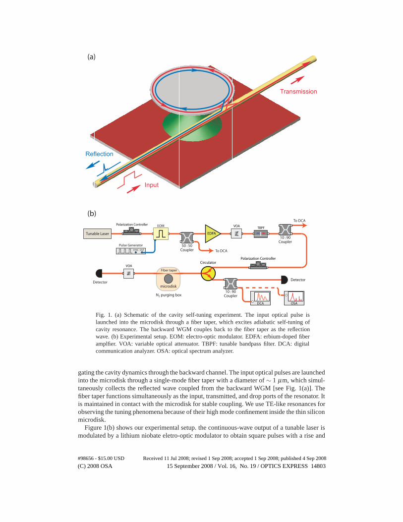
Fig. 1. (a) Schematic of the cavity self-tuning experiment. The input optical pulse islaunched into the microdisk through a fiber taper, which excites adiabatic self-tuning ofcavity resonance. The backward WGM couples back to the fiber taper as the reflectionwave. (b) Experimental setup. EOM: electro-optic modulator. EDFA: erbium-doped fiberamplfier. VOA: variable optical attenuator. TBPF: tunable bandpass filter. DCA: digitalcommunication analyzer. OSA: optical spectrum analyzer.
gating the cavity dynamics through the backward channel. The input optical pulses are launchedinto the microdisk through a single-mode fiber taper with a diameter of ∼ 1 μm, which simul-taneously collects the reflected wave coupled from the backward WGM [see Fig. 1(a)]. Thefiber taper functions simultaneously as the input, transmitted, and drop ports of the resonator. Itis maintained in contact with the microdisk for stable coupling. We use TE-like resonances forobserving the tuning phenomena because of their high mode confinement inside the thin siliconmicrodisk.
Figure 1(b) shows our experimental setup. the continuous-wave output of a tunable laser ismodulated by a lithium niobate eletro-optic modulator to obtain square pulses with a rise and
#98656 - $15.00 USD Received 11 Jul 2008; revised 1 Sep 2008; accepted 1 Sep 2008; published 4 Sep 2008
(C) 2008 OSA 15 September 2008 / Vol. 16, No. 19 / OPTICS EXPRESS 14803
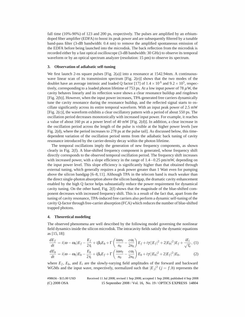
fall time (10%-90%) of 123 and 200 ps, respectively. The pulses are amplified by an erbium-doped fiber amplifier (EDFA) to boost its peak power and are subsequently filtered by a tunableband-pass filter (3-dB bandwidth: 0.4 nm) to remove the amplified spontaneous emission ofthe EDFA before being launched into the microdisk. The back reflection from the microdisk isrecorded either by a fast optical oscilloscope (3-dB bandwidth: 30 GHz) to observe its temporalwaveform or by an optical spectrum analyzer (resolution: 15 pm) to observe its spectrum.
3. Observation of adiabatic self-tuning
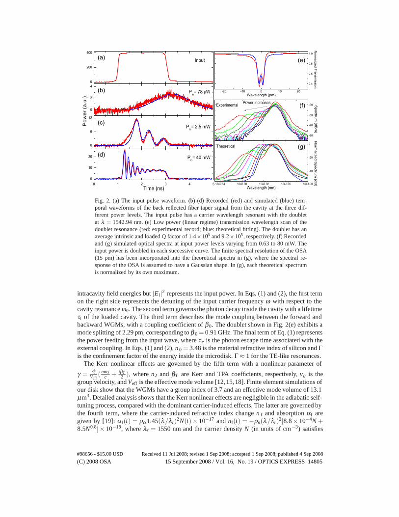
We first launch 2-ns square pulses [Fig. 2(a)] into a resonance at 1542.94nm. A continuous-wave linear scan of its transmission spectrum [Fig. 2(e)] shows that the two modes of thedoublet have an average intrinsic and loaded Q factor [17] of 1.4×10 6 and 9.2×10⁵, respec-tively, corresponding to a loaded photon lifetime of 753 ps. At a low input power of 78 μW, thecavity behaves linearly and its reflection wave shows a clear resonance buildup and ringdown[Fig. 2(b)]. However, when the input power increases, TPA-generated free carriers dynamicallytune the cavity resonance during the resonance buildup, and the reflected signal starts to os-cillate significantly across its entire temporal waveform. With an input peak power of 2.5 mW[Fig. 2(c)], the waveform exhibits a clear oscillatory pattern with a period of about 550 ps. Theoscillation period decreases monotonically with increased input power. For example, it reachesa value of about 160 ps at a power level of 40 mW [Fig. 2(d)]. In addition, a clear increase inthe oscillation period across the length of the pulse is visible at the higher power levels [seeFig. 2(d), where the period increases to 278 ps at the pulse tail]. As discussed below, this time-dependent variation of the oscillation period stems from the adiabatic back tuning of cavityresonance introduced by the carrier-density decay within the photon lifetime.
The temporal oscillations imply the generation of new frequency components, as shownclearly in Fig. 2(f). A blue-shifted frequency component is generated, whose frequency shiftdirectly corresponds to the observed temporal oscillation period. The frequency shift increaseswith increased power, with a slope efficiency in the range of 1.4−0.25 pm/mW, depending onthe input power level. This slope efficiency is significantly higher than that obtained throughexternal tuning, which generally requires a peak power greater than 1 Watt even for pumpingabove the silicon bandgap [6–8, 11]. Although TPA in the telecom band is much weaker thanthe direct single-photon absorption above the silicon bandgap, the dramatic cavity enhancementenabled by the high Q factor helps substantially reduce the power requirement for dynamicalcavity tuning. On the other hand, Fig. 2(f) shows that the magnitude of the blue-shifted com-ponent decreases with increased frequency shift. This is a result of the fact that, apart from thetuning of cavity resonance, TPA-induced free carriers also perform a dynamic self-tuning of thecavity Q-factor through free-carrier absorption (FCA) which reduces the number of blue-shiftedtrapped photons.
4. Theoretical modeling
The observed phenomena are well described by the following model governing the nonlinearfield dynamics inside the silicon microdisk. The intracavity fields satisfy the dynamic equationsas [15, 18]:
dE f
dt= i(ω −ω0)Ef − Ef
2τt+ iβ0Eb + Γ
(iωnf
n0− cαf
2n0
)Ef + iγ(|Ef |2 + 2|Eb|2)Ef +
iEi√τe
, (1)
dEb
dt= i(ω −ω0)Eb − Eb
2τt+ iβ0Ef + Γ
(iωnf
n0− cαf
2n0
)Eb + iγ(|Eb|2 + 2|Ef |2)Eb, (2)
where E f , Eb, and Ei are the slowly-varying field amplitudes of the forward and backwardWGMs and the input wave, respectively, normalized such that |E j|2 ( j = f ,b) represents the
#98656 - $15.00 USD Received 11 Jul 2008; revised 1 Sep 2008; accepted 1 Sep 2008; published 4 Sep 2008
(C) 2008 OSA 15 September 2008 / Vol. 16, No. 19 / OPTICS EXPRESS 14804
(a) (e)
(f)
(b)
(c)
(d)(g)
Fig. 2. (a) The input pulse waveform. (b)-(d) Recorded (red) and simulated (blue) tem-poral waveforms of the back reflected fiber taper signal from the cavity at the three dif-ferent power levels. The input pulse has a carrier wavelength resonant with the doubletat λ = 1542.94 nm. (e) Low power (linear regime) transmission wavelength scan of thedoublet resonance (red: experimental record; blue: theoretical fitting). The doublet has anaverage intrinsic and loaded Q factor of 1.4×10⁶ and 9.2×10⁵, respectively. (f) Recordedand (g) simulated optical spectra at input power levels varying from 0.63 to 80 mW. Theinput power is doubled in each successive curve. The finite spectral resolution of the OSA(15 pm) has been incorporated into the theoretical spectra in (g), where the spectral re-sponse of the OSA is assumed to have a Gaussian shape. In (g), each theoretical spectrumis normalized by its own maximum.
intracavity field energies but |Ei|2 represents the input power. In Eqs. (1) and (2), the first termon the right side represents the detuning of the input carrier frequency ω with respect to thecavity resonance ω0. The second term governs the photon decay inside the cavity with a lifetimeτt of the loaded cavity. The third term describes the mode coupling between the forward andbackward WGMs, with a coupling coefficient of β0. The doublet shown in Fig. 2(e) exhibits amode splitting of 2.29 pm, corresponding to β 0 = 0.91 GHz. The final term of Eq. (1) representsthe power feeding from the input wave, where τ e is the photon escape time associated with theexternal coupling. In Eqs. (1) and (2), n 0 = 3.48 is the material refractive index of silicon and Γis the confinement factor of the energy inside the microdisk. Γ ≈ 1 for the TE-like resonances.
The Kerr nonlinear effects are governed by the fifth term with a nonlinear parameter of
γ =v2g
Veff(ωn2
c + iβT2 ), where n2 and βT are Kerr and TPA coefficients, respectively, vg is the
group velocity, and Veff is the effective mode volume [12,15,18]. Finite element simulations ofour disk show that the WGMs have a group index of 3.7 and an effective mode volume of 13.1μm3. Detailed analysis shows that the Kerr nonlinear effects are negligible in the adiabatic self-tuning process, compared with the dominant carrier-induced effects. The latter are governed bythe fourth term, where the carrier-induced refractive index change n f and absorption αf aregiven by [19]: αf(t) = ρα1.45(λ/λr)2N(t)× 10−17 and nf(t) = −ρn(λ/λr)2[8.8× 10−4N +8.5N0.8]× 10−18, where λr = 1550 nm and the carrier density N (in units of cm−3) satisfies
#98656 - $15.00 USD Received 11 Jul 2008; revised 1 Sep 2008; accepted 1 Sep 2008; published 4 Sep 2008
(C) 2008 OSA 15 September 2008 / Vol. 16, No. 19 / OPTICS EXPRESS 14805
[12, 15]dNdt
=v2
gβT
2h̄ωV 2eff
(|Ef |4 + 4|Ef |2|Eb|2 + |Eb|4)− N
τ0, (3)
with an effective carrier lifetime of τ0 and a TPA coefficient of βT = 0.5 cm/GW. In the ex-pressions of αf and nf, the two factors ρα and ρn are correction factors (based upon fittingto the measured data) for the magnitude of carrier effects relative to the empirical model ofRef. [19]. They also include all possible uncertainties in the TPA coefficient, effective modevolume, group velocity, etc., which may affect the magnitude of generated carrier density. Ourmodeling of the experimental results indicates ρα = 1.5 and ρn = 0.55.
A detailed characterization of our experimental system shows that the back reflection signalhas a second source in addition to the already discussed high-Q backward WGM of the mi-crodisk. The second component of the reflected signal stems from coupling of the input waveto low-Q background modes of the microdisk. Parasitic coupling to these modes is generallyunavoidable in the microdisk geometry due to the large number of higher-order radial modes.Due to their short photon lifetimes and broad spectral features, coupling to the background diskmodes results in a nearly frequency independent direct reflection signal proportional to the inputwave. The presence of background modes of the disk was confirmed by tuning off-resonancefrom the high-Q cavity modes and measuring the reflected signal. The magnitude of the detunedreflected signal was found to be |η |2 = (0.013)2 of the input pulse power (with the fiber taperdetached from the disk the reflected signal was negligible). Taking into account both compo-nents of the reflected signal, the total back-reflected wave is then given by E r = ηEi + iEb/
√τe,
where |Er|2 has a unit of optical power. Comparison of the measured reflected waveform to theabove model indicates that η = 0.013i, where the relative π/2 phase shift is introduced by thesuperposition of background disk modes with various detunings from the input wave frequency.
The experimentally recorded input pulse [Fig. 2(a)] is used as the input waveform for simu-lation. The simulated temporal waveforms are plotted in Fig. 2(b)-(d) in a direct comparison tothe experimental records. Clearly, theory and experiments agree well at various power levels.These simulations indicate a carrier lifetime of 2.5 ns. Accordingly, The corresponding sim-ulated spectra [Fig. 2(g)] show close agreement with the experimental ones [Fig. 2(f)]. Thehigher magnitude of the fundamental frequency component in the experimental spectra is dueto the finite extinction ratio of the electro-optic modulator which introduces a nonzero powerfloor on the input wave.
The physical mechanism underlying the adiabatic self-tuning process can be well understoodthrough Fig. 3, where we plot the simulated spectrograms of the intracavity forward WGM,backward WGM, the reflected wave, together with their temporal waveforms and the carrierdynamics at a power level of 40 mW. Comparing Fig. 3(a), (b), (c) and (e), we can see clearlythat the forefront of the intracavity wave remains at its original frequency since negligible car-riers are created before the intracavity power builds up to a significant level for efficient TPA.However, in the time window between 1.14 and 1.24 ns, carrier density increases rapidly dur-ing a short time period of ∼100 ps, which simultaneously detunes the cavity resonance andthus drags the frequency of trapped photons towards blue. The blue tuning of the cavity reso-nance starts to quench any further power input, leading to a saturation of the intracavity powerat ∼1.24 ns. After this time, the carrier density reaches its quasi-steady state and the photonfrequency stops further tuning. The trapped photons at this blue-tuned frequency thus decayat a slightly reduced photon lifetime due to FCA. For the forward WGM, there are two fre-quency components simultaneously circulating inside the cavity [Fig. 3(b)], leading to beatingon its temporal waveform [Fig. 3(e), blue]. For the backward WGM, however, its energy isdominantly stored at the blue-shifted frequency [Fig. 3(c)] since it is scattered from the forwardWGM whose frequency is blue-shifted by the cavity tuning. As a result, less oscillations appear
#98656 - $15.00 USD Received 11 Jul 2008; revised 1 Sep 2008; accepted 1 Sep 2008; published 4 Sep 2008
(C) 2008 OSA 15 September 2008 / Vol. 16, No. 19 / OPTICS EXPRESS 14806
0
2
4 0
-0.54
-1.08
n f
N (c
m-3
)
×10-4×10¹⁶
Wav
elen
gth
(pm
)
-60
-40
-20
0
20
Wav
elen
gth
(pm
)
-60
-40
-20
0
20
Wav
elen
gth
(pm
)
-60
-40
-20
0
20
Pow
er
0
0.5
1
−20 dB
−10 dB
0
Time (ns)1 1.5 2 2.5 3 3.5
Spectrum (dB)0-40 -20
(a)
(b)
(c)
(d)
(e)
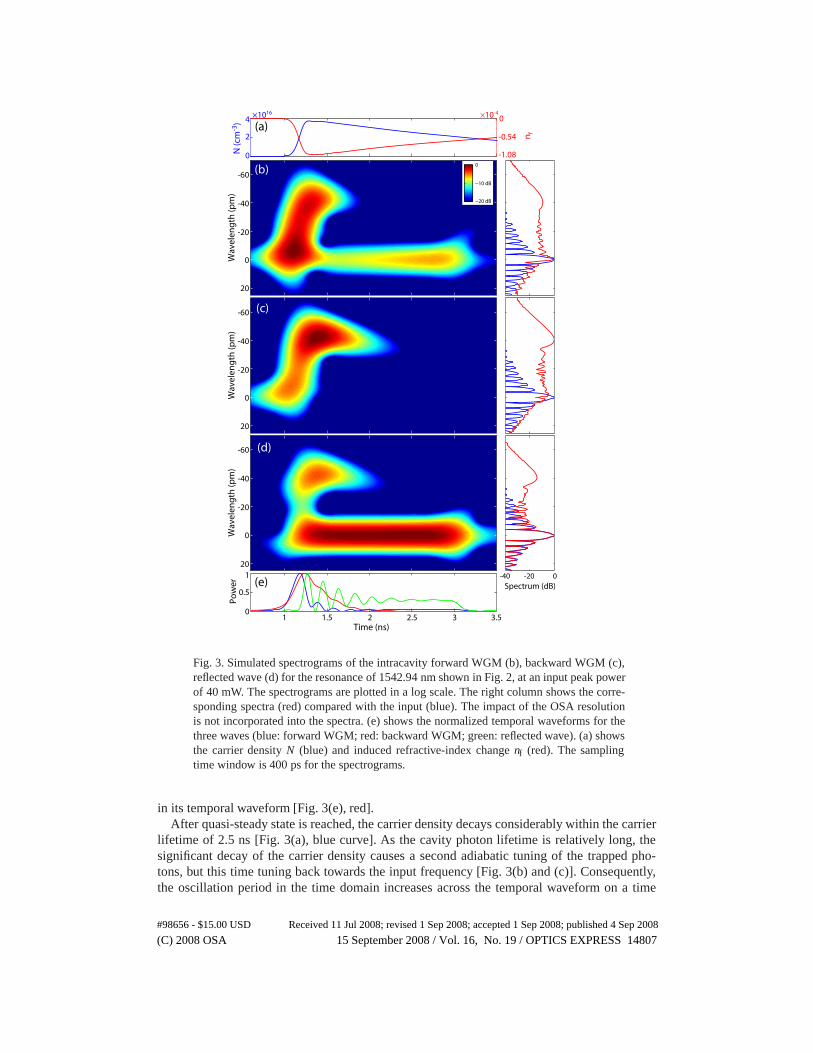
Fig. 3. Simulated spectrograms of the intracavity forward WGM (b), backward WGM (c),reflected wave (d) for the resonance of 1542.94 nm shown in Fig. 2, at an input peak powerof 40 mW. The spectrograms are plotted in a log scale. The right column shows the corre-sponding spectra (red) compared with the input (blue). The impact of the OSA resolutionis not incorporated into the spectra. (e) shows the normalized temporal waveforms for thethree waves (blue: forward WGM; red: backward WGM; green: reflected wave). (a) showsthe carrier density N (blue) and induced refractive-index change nf (red). The samplingtime window is 400 ps for the spectrograms.
in its temporal waveform [Fig. 3(e), red].After quasi-steady state is reached, the carrier density decays considerably within the carrier
lifetime of 2.5 ns [Fig. 3(a), blue curve]. As the cavity photon lifetime is relatively long, thesignificant decay of the carrier density causes a second adiabatic tuning of the trapped pho-tons, but this time tuning back towards the input frequency [Fig. 3(b) and (c)]. Consequently,the oscillation period in the time domain increases across the temporal waveform on a time
#98656 - $15.00 USD Received 11 Jul 2008; revised 1 Sep 2008; accepted 1 Sep 2008; published 4 Sep 2008
(C) 2008 OSA 15 September 2008 / Vol. 16, No. 19 / OPTICS EXPRESS 14807
0
5
10 0×10-4×1016
-1.12
-2.24
n f
N (c
m-3
)W
avel
engt
h (p
m)
-60
-40
-20
0
20
Wav
elen
gth
(pm
)
-60
-40
-20
0
20
Wav
elen
gth
(pm
)
-60
-40
-20
0
20
Pow
er
0
0.5
1
−20 dB
−10 dB
0
Time (ns)1 1.5 2 2.5 3 3.5
Spectrum (dB)0-40 -20
(a)
(b)
(c)
(d)
(e)
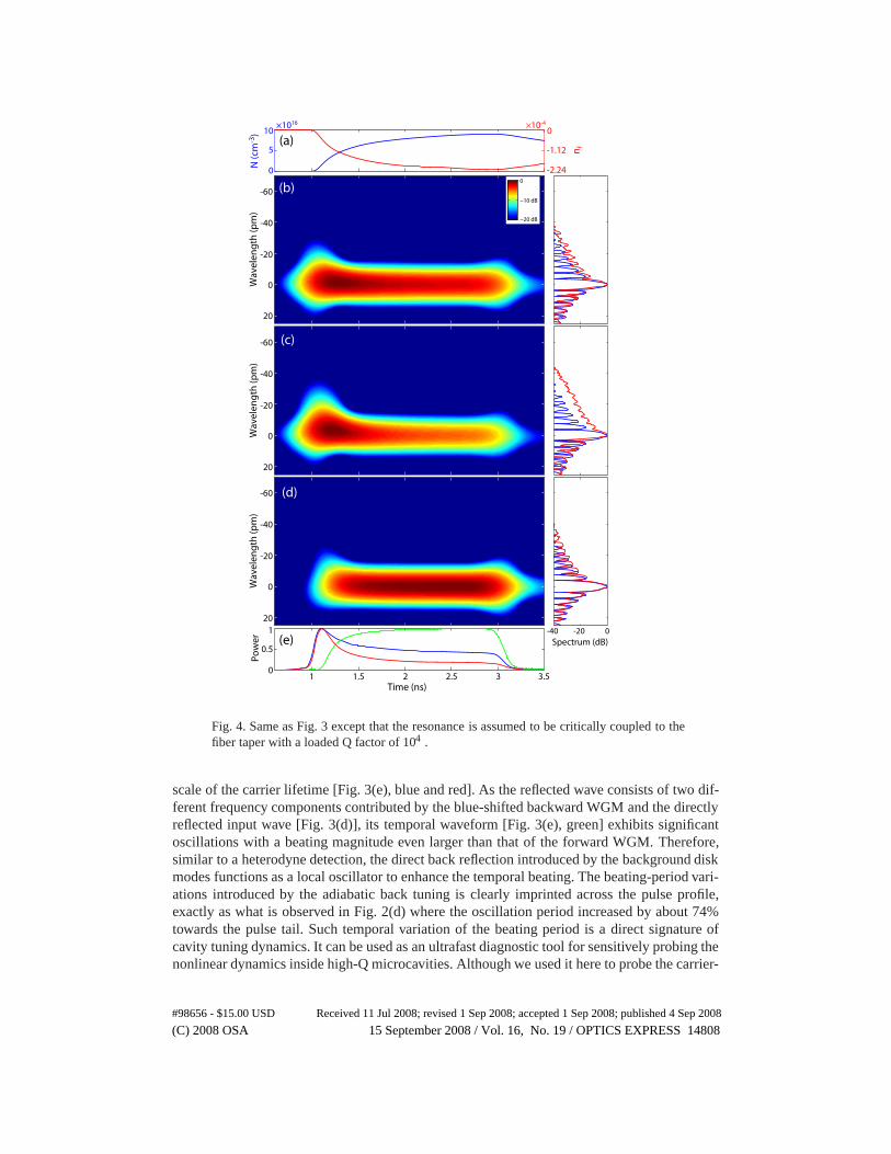
Fig. 4. Same as Fig. 3 except that the resonance is assumed to be critically coupled to thefiber taper with a loaded Q factor of 104 .
scale of the carrier lifetime [Fig. 3(e), blue and red]. As the reflected wave consists of two dif-ferent frequency components contributed by the blue-shifted backward WGM and the directlyreflected input wave [Fig. 3(d)], its temporal waveform [Fig. 3(e), green] exhibits significantoscillations with a beating magnitude even larger than that of the forward WGM. Therefore,similar to a heterodyne detection, the direct back reflection introduced by the background diskmodes functions as a local oscillator to enhance the temporal beating. The beating-period vari-ations introduced by the adiabatic back tuning is clearly imprinted across the pulse profile,exactly as what is observed in Fig. 2(d) where the oscillation period increased by about 74%towards the pulse tail. Such temporal variation of the beating period is a direct signature ofcavity tuning dynamics. It can be used as an ultrafast diagnostic tool for sensitively probing thenonlinear dynamics inside high-Q microcavities. Although we used it here to probe the carrier-
#98656 - $15.00 USD Received 11 Jul 2008; revised 1 Sep 2008; accepted 1 Sep 2008; published 4 Sep 2008
(C) 2008 OSA 15 September 2008 / Vol. 16, No. 19 / OPTICS EXPRESS 14808
density evolution, it can also be used to investigate other nonlinear cavity dynamics, i.e., theopto-mechanical kinetics if the cavity tuning is introduced by opto-mechanical coupling [4].The power requirement for adiabatic self-tuning can be further reduced by using a smaller disk,since the tuning efficiency is inversely proportional to the square of the effective mode volume[see Eq. (3)].
The adiabatic self-tuning process depends strongly on the relative magnitude of the cavitytuning time and the photon lifetime. It disappears when the latter becomes smaller than theformer, where the trapped photons do not have enough time to experience the cavity tuningbefore dying out. Figure 4 shows a simulation result for a critically-coupled resonance witha loaded Q of 104, corresponding to a photon lifetime of 8 ps. Although the carrier densitycontinuously increases to a level even higher than that for the high-Q mode shown in Fig. 3,it occurs in a time scale much longer than the photon lifetime. Consequently, the optical fieldsdo not show a frequency shift and the oscillatory pattern is absent in their temporal waveforms,which exhibit a long pulse tail. Therefore, in practice, the adiabatic self-tuning process can beobserved experimentally only in resonances with a Q factor above a certain level.
5. Applications to pulse compression and tunable delay
Figures 2 and 3 show that the quenching of power feeding introduced by the adiabatic self-tuning process leaves a dominant peak in the pulse front, with an oscillatory tail whose temporalduration depends on the cavity photon lifetime. This mechanism readily provides an efficientway for pulse compression, since the oscillatory tail can be easily suppressed by changingthe cavity Q factor to reduce the photon lifetime. Figure 5 shows such an example, where welaunched the same 2-ns pulses into a resonance at 1551.27nm which has a loaded and intrinsic Qfactor of 1.46×10⁵ and 3.28×10⁵ [inset of Fig. 5(a)], respectively. At a low power of 0.18 mWwhen the carrier effects are negligible [Fig. 5(a), blue curve], the reflected wave exhibits a fastresonance buildup and ringdown because of the short photon lifetime of 120 ps. When the inputpower increases, the adiabatic self-tuning process starts to significantly compress the temporalwidth of the pulse. In contrast to the previous high-Q mode, the short photon lifetime suppressesconsiderably the oscillation in the pulse tail, leaving only a nearly symmetric squeezed pulseat the leading edge. Its full width at half maximum reaches a value of 156 ps at the powerlevel of 22.4 mW [Fig. 5(a), red curve], which is about one order of magnitude smaller thanthe carrier lifetime. The compressed pulse width decreases further with higher input power. Inprinciple, the generated pulse duration is ultimately limited only by the cavity round-trip timesince the quenching speed of the external power feeding is determined by the magnitude of thecarrier-induced extra phase shift per round trip.
Figure 3 shows that the onset of adiabatic self-tuning is determined by the time when the car-rier density starts a rapid growth. As the carrier-density growth depends on the power feedingprocess, which itself is affected by the frequency detuning from the cavity resonance, we canuse the detuning to control the temporal delay of the squeezed pulse. This is shown in Fig. 5(b).When the input wavelength is detuned by about 16 pm on the blue side of the resonance, theintracavity power only grows slowly in the beginning along with the adiabtic tuning of the cav-ity resonance. However, as the plasma-dispersion effect moves the resonance towards the inputwavelength, the power feeding accelerates with time until a point where fast adiabatic self-tuning occurs and generates a squeezed pulse. Consequently, the generated pulse is delayed by115 ps [Fig. 5(b), blue curve] compared with the on-resonance case [Fig. 5(b), red curve]. Themagnitude of time delay can be controlled by the input power as well as the frequency detun-ing. For example, it increases to 309 ps when the input power reduces to 5.6 mW. Therefore,adiabatic self-tuning provides a “slow-light” like effect for tunable time delay. In practice, asubstantial increase of time delay can be realized by using a cascade configuration with mul-
#98656 - $15.00 USD Received 11 Jul 2008; revised 1 Sep 2008; accepted 1 Sep 2008; published 4 Sep 2008
(C) 2008 OSA 15 September 2008 / Vol. 16, No. 19 / OPTICS EXPRESS 14809
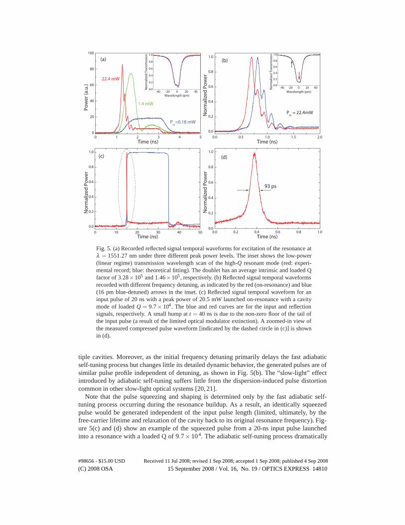
Fig. 5. (a) Recorded reflected signal temporal waveforms for excitation of the resonance atλ = 1551.27 nm under three different peak power levels. The inset shows the low-power(linear regime) transmission wavelength scan of the high-Q resonant mode (red: experi-mental record; blue: theoretical fitting). The doublet has an average intrinsic and loaded Qfactor of 3.28×10⁵ and 1.46×10⁵, respectively. (b) Reflected signal temporal waveformsrecorded with different frequency detuning, as indicated by the red (on-resonance) and blue(16 pm blue-detuned) arrows in the inset. (c) Reflected signal temporal waveform for aninput pulse of 20 ns with a peak power of 20.5 mW launched on-resonance with a cavitymode of loaded Q = 9.7× 10⁴. The blue and red curves are for the input and reflectionsignals, respectively. A small hump at t = 40 ns is due to the non-zero floor of the tail ofthe input pulse (a result of the limited optical modulator extinction). A zoomed-in view ofthe measured compressed pulse waveform [indicated by the dashed circle in (c)] is shownin (d).
tiple cavities. Moreover, as the initial frequency detuning primarily delays the fast adiabaticself-tuning process but changes little its detailed dynamic behavior, the generated pulses are ofsimilar pulse profile independent of detuning, as shown in Fig. 5(b). The “slow-light” effectintroduced by adiabatic self-tuning suffers little from the dispersion-induced pulse distortioncommon in other slow-light optical systems [20, 21].
Note that the pulse squeezing and shaping is determined only by the fast adiabatic self-tuning process occurring during the resonance buildup. As a result, an identically squeezedpulse would be generated independent of the input pulse length (limited, ultimately, by thefree-carrier lifetime and relaxation of the cavity back to its original resonance frequency). Fig-ure 5(c) and (d) show an example of the squeezed pulse from a 20-ns input pulse launchedinto a resonance with a loaded Q of 9.7× 10⁴. The adiabatic self-tuning process dramatically
#98656 - $15.00 USD Received 11 Jul 2008; revised 1 Sep 2008; accepted 1 Sep 2008; published 4 Sep 2008
(C) 2008 OSA 15 September 2008 / Vol. 16, No. 19 / OPTICS EXPRESS 14810
compresses the pulse waveform, leaving only a sharp spike at the leading edge. The full widthat half maximum of the compressed pulse is only 93 ps, corresponding to a temporal squeezingfactor of more than 200. From an application point of view, the adiabatic self-tuning processprovides an efficient way for flexible pulse compression, with a compressed pulse width con-tinuously tunable by input peak power, and an efficiency more than two orders of magnitudehigher than the scheme based on FCA inside a silicon waveguide [22].
6. Conclusion
We have demonstrated a novel approach for dynamically tuning a silicon microdisk resonator,and used it to realize various optical functionalities like pulse compression, shaping, and tun-able time delay. As the compressed pulse shape is primarily determined by the cavity tuningdynamics, it is fairly insensitive to temporal distortion and fluctuations on the input pulse andthus may provide an efficient way for signal regeneration. Additional refinement of the com-pressed pulse shape can be realized by optimization of the cavity Q-factor. Although we use theback reflection from the microdisk to demonstrate the phenomena, in practice, a second fiber ta-per or bus waveguide can be used as a drop port for more effective extraction of the compressedpulse. On the other hand, the device can be placed in a cascade configuration for multi-channeloperation. In particular, in contrast to other carrier-based signal modulation schemes [23, 24]whose modulation speeds are primarily limited by the carrier lifetime, the adiabatic self-tuningprocess does not suffer from such a carrier-lifetime bottleneck. While the repetition rate of theprocessed signal may be affected by the carrier lifetime, it can be significantly improved byvarious carrier-lifetime engineering techniques. Therefore, our demonstrated scheme may finduseful applications in optical packet switching, label swapping, channel routing, etc., in futurehigh-speed integrated photonic interconnects.
Acknowledgment
The authors would like to thank Jidong Zhang, Matt Eichenfield, Raviv Perahia, and Paul Bar-clay for helpful discussions. This work is supported by Defense Advanced Research ProjectsAgency (DARPA) under the programs of Parametric Optical Processes and Systems (POPS)and Electronic and Photonic Integrated Circuits (EPIC).
#98656 - $15.00 USD Received 11 Jul 2008; revised 1 Sep 2008; accepted 1 Sep 2008; published 4 Sep 2008
(C) 2008 OSA 15 September 2008 / Vol. 16, No. 19 / OPTICS EXPRESS 14811