Embed Size (px)
Citation preview
OpenStage M3/M3 PlusOpenStage M3 Ex/M3 Ex Pluson HiPath Cordless Alarm and Emergency Call Configuration
Administrator Documentation
A31003-M2000-M103-2-A9
Our Quality and Environmental Management Systems are implemented according to the requirements of the ISO9001 and ISO14001 standards and are certified by an external certification company.
Copyright © Unify GmbH & Co. KG 07/2014 Hofmannstr. 51, 81379 Munich/Germany
All rights reserved.
Reference No.: A31003-M2000-M103-2-A9
The information provided in this document contains merely general descriptions or characteristics of performance which in case of actual use do not always apply as described or which may change as a result of further development of the products. An obligation to provide the respective characteristics shall only exist if expressly agreed in the terms of contract.
Availability and technical specifications are subject to change without notice.
Unify, OpenScape, OpenStage and HiPath are registered trademarks of Unify GmbH & Co. KG. All other company, brand, product and service names are trademarks or registered trademarks of their respective holders.
unify.com
SHB_PNG_TOC.fm
For internal use only Contents
Contents 0
Tables . . . . . . . . . . . . . . . . . . . . . . . . . . . . . . . . . . . . . . . . . . . . . . . . . . . . . . . . . . . . . . . . 0-3
1 Introduction. . . . . . . . . . . . . . . . . . . . . . . . . . . . . . . . . . . . . . . . . . . . . . . . . . . . . . . . . . 1-11.1 Overview . . . . . . . . . . . . . . . . . . . . . . . . . . . . . . . . . . . . . . . . . . . . . . . . . . . . . . . . . . . 1-11.2 Privacy and data security. . . . . . . . . . . . . . . . . . . . . . . . . . . . . . . . . . . . . . . . . . . . . . . 1-21.3 Notational conventions and symbols used. . . . . . . . . . . . . . . . . . . . . . . . . . . . . . . . . . 1-3
2 Operating modes . . . . . . . . . . . . . . . . . . . . . . . . . . . . . . . . . . . . . . . . . . . . . . . . . . . . . 2-12.1 Mode dependent functions . . . . . . . . . . . . . . . . . . . . . . . . . . . . . . . . . . . . . . . . . . . . . 2-12.2 Basic Mode: Availability, alarm and emergency call . . . . . . . . . . . . . . . . . . . . . . . . . . 2-22.3 Alarm Mode: Freely configurable monitoring . . . . . . . . . . . . . . . . . . . . . . . . . . . . . . . 2-32.4 PNG Mode: Monitoring in compliance with BGR 139 . . . . . . . . . . . . . . . . . . . . . . . . . 2-3
2.4.1 HiPath PNA (personal alarm system) . . . . . . . . . . . . . . . . . . . . . . . . . . . . . . . . . . 2-32.4.1.1 In alarm status: Callback by HNA. . . . . . . . . . . . . . . . . . . . . . . . . . . . . . . . . . 2-4
3 Configuration and activation . . . . . . . . . . . . . . . . . . . . . . . . . . . . . . . . . . . . . . . . . . . . 3-13.1 Overview . . . . . . . . . . . . . . . . . . . . . . . . . . . . . . . . . . . . . . . . . . . . . . . . . . . . . . . . . . . 3-1
3.1.1 [Mode] Activation . . . . . . . . . . . . . . . . . . . . . . . . . . . . . . . . . . . . . . . . . . . . . . . . . 3-13.1.2 Configuration. . . . . . . . . . . . . . . . . . . . . . . . . . . . . . . . . . . . . . . . . . . . . . . . . . . . . 3-23.1.3 Operating mode (OpenStage M3 Plus and OpenStage M3 Ex Plus only) . . . . . . 3-23.1.4 Display Rotate (OpenStage M3 Plus and OpenStage M3 Ex Plus only) . . . . . . . 3-3
3.2 Configuration menu . . . . . . . . . . . . . . . . . . . . . . . . . . . . . . . . . . . . . . . . . . . . . . . . . . . 3-43.2.1 Alarm Konfiguration. . . . . . . . . . . . . . . . . . . . . . . . . . . . . . . . . . . . . . . . . . . . . . . . 3-4
3.2.1.1 Alarms . . . . . . . . . . . . . . . . . . . . . . . . . . . . . . . . . . . . . . . . . . . . . . . . . . . . . . 3-43.2.1.2 [Mode] Activation . . . . . . . . . . . . . . . . . . . . . . . . . . . . . . . . . . . . . . . . . . . . . 3-123.2.1.3 Control Ports . . . . . . . . . . . . . . . . . . . . . . . . . . . . . . . . . . . . . . . . . . . . . . . . 3-133.2.1.4 Techn. Warning . . . . . . . . . . . . . . . . . . . . . . . . . . . . . . . . . . . . . . . . . . . . . . 3-143.2.1.5 Adjust Sensor . . . . . . . . . . . . . . . . . . . . . . . . . . . . . . . . . . . . . . . . . . . . . . . 3-153.2.1.6 Reset to default . . . . . . . . . . . . . . . . . . . . . . . . . . . . . . . . . . . . . . . . . . . . . . 3-163.2.1.7 Alarm Signal PIN (only in Alarm and PNG Mode) . . . . . . . . . . . . . . . . . . . . 3-16
3.2.2 Emergency Call . . . . . . . . . . . . . . . . . . . . . . . . . . . . . . . . . . . . . . . . . . . . . . . . . 3-173.2.2.1 Emergency Call . . . . . . . . . . . . . . . . . . . . . . . . . . . . . . . . . . . . . . . . . . . . . . 3-183.2.2.2 Resetting emergency call configuration to defaults . . . . . . . . . . . . . . . . . . . 3-19
3.2.3 Service PIN . . . . . . . . . . . . . . . . . . . . . . . . . . . . . . . . . . . . . . . . . . . . . . . . . . . . 3-193.3 Exporting and transmitting the configuration . . . . . . . . . . . . . . . . . . . . . . . . . . . . . . . 3-21
4 Control ports and alarm destinations. . . . . . . . . . . . . . . . . . . . . . . . . . . . . . . . . . . . . 4-14.1 Syntax of the control ports and alarm destinations . . . . . . . . . . . . . . . . . . . . . . . . . . . 4-1
4.1.1 Calls to the alarm server . . . . . . . . . . . . . . . . . . . . . . . . . . . . . . . . . . . . . . . . . . . . 4-14.1.2 Calls from the alarm server . . . . . . . . . . . . . . . . . . . . . . . . . . . . . . . . . . . . . . . . . . 4-2
4.2 Example. . . . . . . . . . . . . . . . . . . . . . . . . . . . . . . . . . . . . . . . . . . . . . . . . . . . . . . . . . . . 4-2
5 Response times under VDE 0825 . . . . . . . . . . . . . . . . . . . . . . . . . . . . . . . . . . . . . . . . 5-1
A31003-M2000-M103-2-76A9, 07/2014Alarm and Emergency Call Configuration, Administrator Documentation 0-1
Contents For internal use only
SHB_PNG_TOC.fm
6 Structure of the Additional Features menu . . . . . . . . . . . . . . . . . . . . . . . . . . . . . . . . . 6-16.1 OpenStage M3/OpenStage M3 Ex . . . . . . . . . . . . . . . . . . . . . . . . . . . . . . . . . . . . . . . . 6-16.2 OpenStage M3 Plus/OpenStage M3 Ex Plus . . . . . . . . . . . . . . . . . . . . . . . . . . . . . . . . 6-3
6.2.1 Operating Mode 1: Basic Mode . . . . . . . . . . . . . . . . . . . . . . . . . . . . . . . . . . . . . . . 6-36.2.2 Operating Mode 2: Alarm Mode . . . . . . . . . . . . . . . . . . . . . . . . . . . . . . . . . . . . . . . 6-66.2.3 Operating Mode 3: PNG Mode. . . . . . . . . . . . . . . . . . . . . . . . . . . . . . . . . . . . . . . . 6-9
Abbreviations . . . . . . . . . . . . . . . . . . . . . . . . . . . . . . . . . . . . . . . . . . . . . . . . . . . . . . . . . . Y-1
Index . . . . . . . . . . . . . . . . . . . . . . . . . . . . . . . . . . . . . . . . . . . . . . . . . . . . . . . . . . . . . . . . . . Z-1
A31003-M2000-M103-2-76A9, 07/20140-2 Alarm and Emergency Call Configuration, Administrator Documentation
SHB_PNG_LOT.fm
For internal use only Tables
Tables 0
Table 2-1 Function overview . . . . . . . . . . . . . . . . . . . . . . . . . . . . . . . . . . . . . . . . . . . 2-1Table 3-1 Parameter – General Settings. . . . . . . . . . . . . . . . . . . . . . . . . . . . . . . . . . 3-5Table 3-2 Parameter – Manual Alarm . . . . . . . . . . . . . . . . . . . . . . . . . . . . . . . . . . . . 3-6Table 3-3 Parameter – Manual Alarm, example . . . . . . . . . . . . . . . . . . . . . . . . . . . . 3-7Table 3-4 Parameter – Non Movement Alarm. . . . . . . . . . . . . . . . . . . . . . . . . . . . . . 3-8Table 3-5 Parameter – Man Down Alarm . . . . . . . . . . . . . . . . . . . . . . . . . . . . . . . . . 3-8Table 3-6 Parameter – Time Alarm . . . . . . . . . . . . . . . . . . . . . . . . . . . . . . . . . . . . . . 3-9Table 3-7 Parameter – Escape Alarm . . . . . . . . . . . . . . . . . . . . . . . . . . . . . . . . . . . 3-10Table 3-8 Parameter – Pull Cord Alarm . . . . . . . . . . . . . . . . . . . . . . . . . . . . . . . . . 3-11Table 3-9 Parameter – Prealarm/Alarming Signal. . . . . . . . . . . . . . . . . . . . . . . . . . 3-12Table 3-10 Parameter – [Mode] Activation . . . . . . . . . . . . . . . . . . . . . . . . . . . . . . . . 3-13Table 3-11 Parameter – Control Ports in Basic Mode . . . . . . . . . . . . . . . . . . . . . . . . 3-14Table 3-12 Parameter – Control Ports in Alarm/PNG Mode . . . . . . . . . . . . . . . . . . . 3-14Table 3-13 Parameter – Techn. Warning . . . . . . . . . . . . . . . . . . . . . . . . . . . . . . . . . 3-15Table 3-14 Parameter – Alarm Signal PIN . . . . . . . . . . . . . . . . . . . . . . . . . . . . . . . . 3-17Table 3-15 Parameter – Emergency Call . . . . . . . . . . . . . . . . . . . . . . . . . . . . . . . . . 3-18Table 4-1 Phone number syntax – Calls to the alarm server . . . . . . . . . . . . . . . . . . 4-1Table 4-2 Phone number syntax – Calls from the alarm server . . . . . . . . . . . . . . . . 4-2Table 4-3 Phone number example . . . . . . . . . . . . . . . . . . . . . . . . . . . . . . . . . . . . . . 4-2Table 5-1 Response times under VDE 0825 . . . . . . . . . . . . . . . . . . . . . . . . . . . . . . . 5-1Table 6-1 Launching the Additional Features - Configuration - Basic Configuration menu
6-1Table 6-2 Additional Features - Configuration - Basic Configuration menu . . . . . . . 6-1Table 6-3 Additional Features - Configuration menu. . . . . . . . . . . . . . . . . . . . . . . . . 6-1Table 6-4 Additional Features - Configuration - Basic Configuration - Alarms menu 6-2Table 6-5 Launching the Additional Features - Configuration - Basic Configuration menu
6-3Table 6-6 Launching the Additional Features - Operating Mode menu. . . . . . . . . . . 6-3Table 6-7 Additional Features - Configuration - Basic Configuration menu . . . . . . . 6-3Table 6-8 Additional Features - Configuration - Basic Configuration menu . . . . . . . 6-4Table 6-9 Additional Features - Configuration menu. . . . . . . . . . . . . . . . . . . . . . . . . 6-4Table 6-10 Additional Features - Configuration - Basic Configuration - Alarms menu 6-5Table 6-11 Additional Features - Configuration - Basic Configuration - Alarms menu 6-5Table 6-12 Launching the Additional Features - Configuration - Alarm Configuration menu
6-6Table 6-13 Launching the Additional Features - Operating Mode menu. . . . . . . . . . . 6-6Table 6-14 Additional Features - Configuration - Alarm Configuration menu . . . . . . . 6-6Table 6-15 Additional Features - Configuration - Alarm Configuration menu . . . . . . . 6-7Table 6-16 Additional Features - Configuration menu. . . . . . . . . . . . . . . . . . . . . . . . . 6-7Table 6-17 Additional Features - Configuration - Alarm Configuration - Alarms menu 6-8
A31003-M2000-M103-2-76A9, 07/2014Alarm and Emergency Call Configuration, Administrator Documentation 0-3
Tables For internal use only
SHB_PNG_LOT.fm
Table 6-18 Additional Features - Configuration - Alarm Configuration - Alarms menu. 6-8Table 6-19 Launching the Additional Features - Configuration - PNG Configuration menu
6-9Table 6-20 Launching the Additional Features - Operating Mode menu . . . . . . . . . . . 6-9Table 6-21 Additional Features - Configuration - PNG Configuration menu. . . . . . . . . 6-9Table 6-22 Additional Features - Configuration - PNG Configuration menu. . . . . . . . 6-10Table 6-23 Additional Features - Configuration menu . . . . . . . . . . . . . . . . . . . . . . . . 6-10Table 6-24 Additional Features - Configuration - PNG Configuration - Alarms menu 6-11Table 6-25 Additional Features - Configuration - PNG Configuration - Alarms menu 6-11
A31003-M2000-M103-2-76A9, 07/20140-4 Alarm and Emergency Call Configuration, Administrator Documentation
SHB_PNG-Einleitung.fm
IntroductionOverview
1 Introduction
Contents
This chapter covers the following topics:
● Section 1.1, "Overview"
● Section 1.2, "Privacy and data security"
● Section 1.3, "Notational conventions and symbols used"
1.1 Overview
The OpenStage M3 Plus and OpenStage M3 Ex Plus handsets can be used as personal alarm devices with voice communication capability (PNG-S) in Alarm Mode and PNG Mode. Various settings are performed on the handset for this purpose, which enable automatic or manual alerting. An alarm and emergency call function is already available in Basic Mode.
The OpenStage M3 and OpenStage M3 Ex handsets do not have alarm sensors, rather they also have an alarm and emergency call function. The function range corresponds to that of Basic Mode.
An emergency call via an alarm key is possible regardless of selecting and activating an operating mode.
The PNG-S monitors the person and reports an alarm when alarm conditions are detected. The following types of alarms and signals are possible:
● Man Down Alarm:The integrated movement sensors identify deviations of approx. 70° from the vertical position of the handset.
● Non Movement Alarm:The integrated movement sensors detect immobility of the handset.
● Escape Alarm:The integrated movement sensors detect sudden, violent movements of the handset.
● Pull Cord Alarm:Removal of a magnetic contact, which is inserted below the handset and can be secured by a cord to the individual, is detected.
● Time Alarm:The operator's ability to respond can be controlled through regular operation of the handset. The user is prompted to input something at set times.
● Manual Alarm:The user can trigger an alarm by pressing the alarm key.
A31003-M2000-M103-2-76A9, 07/2014Alarm and Emergency Call Configuration, Administrator Documentation 1-1
Introduction
SHB_PNG-Einleitung.fm
Privacy and data security
● Technical Warning Signal:The handset detects local technical faults or DPS requests. These are signalled to the user. Example: The handset is out of range or the battery charge is too low. The user can subsequently initiate measures in order to resolve the fault.
>All settings that are non BGR 139-compliant are not permitted for BGR 139 applications.
A prealarm informs the monitored persons of an impending alarm. The alarm can still be reset during the prealarm time in order to avoid false alarms.
The response time, prealarm time, possibly sensitivity level, alarm signal and alarm destination can be configured for each alarm type.
1.2 Privacy and data security
This telephone system uses and processes personal data, for example in the case of call detail recording, display messages and customer data recording.
In Germany, the processing and use of such data is subject to various regulations, including those of the Federal Data Protection Law (Bundesdatenschutzgesetz, BDSG). Observe all applicable laws in other countries.
Employees of Unify GmbH & Co. KG are bound to safeguard trade secrets and personal data under the terms of the company's work rules.
A conscientious and responsible approach helps protect data and ensure privacy:
● Use the password features of the system with no exceptions: Change the default password immediately.
● Never give passwords to an unauthorised person, for example in the form of a note.
● Prevent unauthorised persons from gaining access to data media, for example on backup disks or printed reports. This applies to service calls as well as storage and transport.
● Ensure that storage media that are no longer required are completely destroyed. Ensure that no sensitive documents are left unprotected.
A31003-M2000-M103-2-76A9, 07/20141-2 Alarm and Emergency Call Configuration, Administrator Documentation
SHB_PNG-Einleitung.fm
IntroductionNotational conventions and symbols used
1.3 Notational conventions and symbols used
>"i" identifies useful information.
7Safety notesHazard information.
This manual uses the following symbols:
A31003-M2000-M103-2-76A9, 07/2014Alarm and Emergency Call Configuration, Administrator Documentation 1-3
SHB_PNG-Modes.fm
Operating modesMode dependent functions
2 Operating modes
The OpenStage M3 Plus and OpenStage M3 Ex Plus handsets can be used as personal alarm devices with voice communication capability (PNG-S).
Depending on the available infrastructure and requirements, different ranges of functions can be defined for the OpenStage M3 Plus and OpenStage M3 Ex Plus handsets, which are grouped under the operating modes Basic Mode (BM), Alarm Mode (AM) and PNG Mode (PNG).
Following input of a service PIN, each operating mode can be configured independently of the others with toggling possible between the different modes.
Contents
This chapter covers the following topics:
● Section 2.1, "Mode dependent functions"
● Section 2.2, "Basic Mode: Availability, alarm and emergency call"
● Section 2.3, "Alarm Mode: Freely configurable monitoring"
● Section 2.4, "PNG Mode: Monitoring in compliance with BGR 139"
● Section 2.4.1, "HiPath PNA (personal alarm system)"
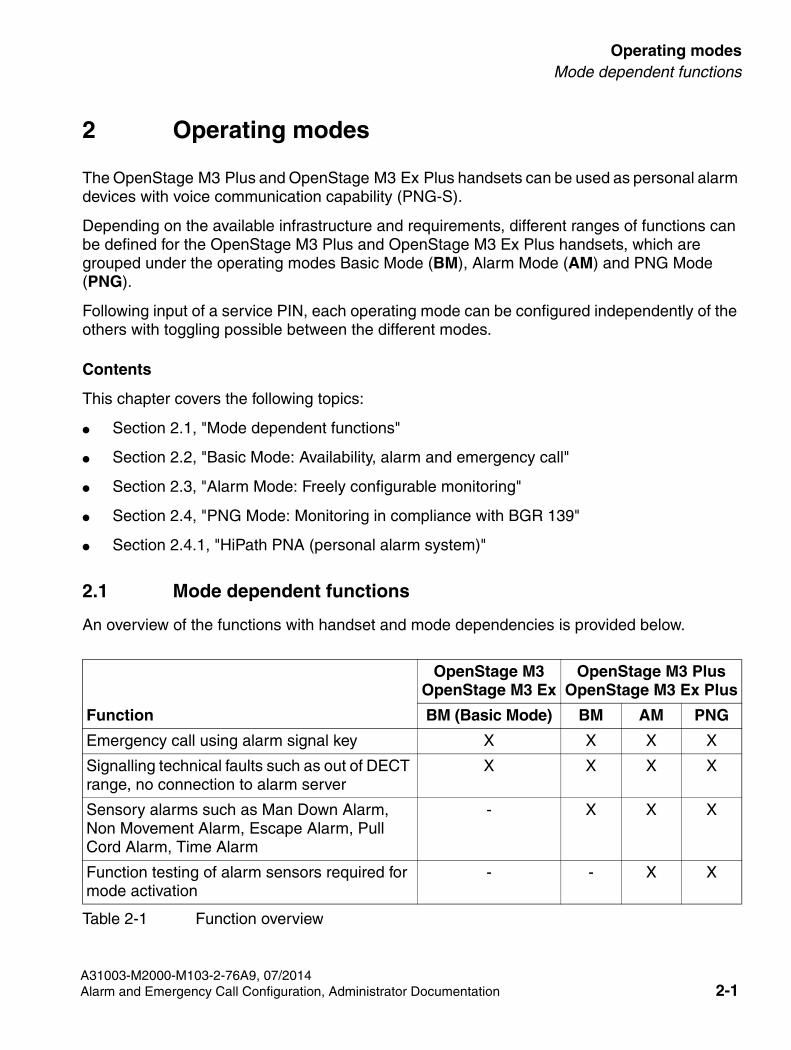
2.1 Mode dependent functions
An overview of the functions with handset and mode dependencies is provided below.
OpenStage M3OpenStage M3 Ex
OpenStage M3 PlusOpenStage M3 Ex Plus
Function BM (Basic Mode) BM AM PNG
Emergency call using alarm signal key X X X X
Signalling technical faults such as out of DECT range, no connection to alarm server
X X X X
Sensory alarms such as Man Down Alarm, Non Movement Alarm, Escape Alarm, Pull Cord Alarm, Time Alarm
- X X X
Function testing of alarm sensors required for mode activation
- - X X
Table 2-1 Function overview
A31003-M2000-M103-2-76A9, 07/2014Alarm and Emergency Call Configuration, Administrator Documentation 2-1
SHB_PNG-Modes.fm
Operating modesBasic Mode: Availability, alarm and emergency call
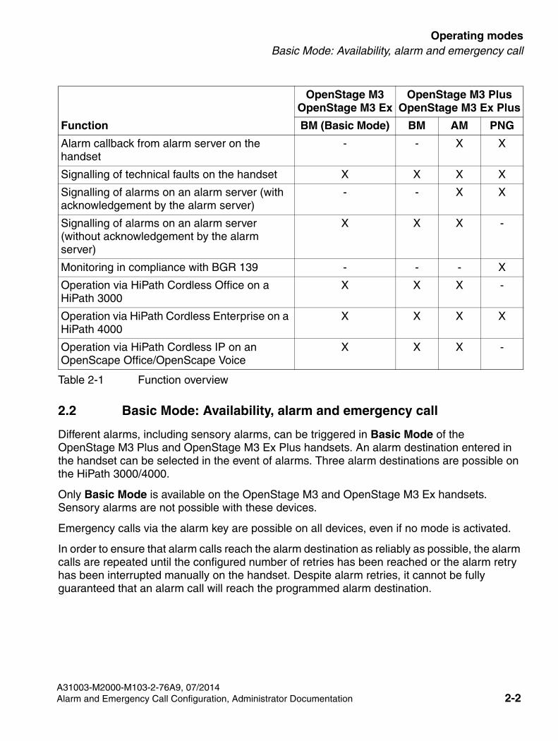
2.2 Basic Mode: Availability, alarm and emergency call
Different alarms, including sensory alarms, can be triggered in Basic Mode of the OpenStage M3 Plus and OpenStage M3 Ex Plus handsets. An alarm destination entered in the handset can be selected in the event of alarms. Three alarm destinations are possible on the HiPath 3000/4000.
Only Basic Mode is available on the OpenStage M3 and OpenStage M3 Ex handsets. Sensory alarms are not possible with these devices.
Emergency calls via the alarm key are possible on all devices, even if no mode is activated.
In order to ensure that alarm calls reach the alarm destination as reliably as possible, the alarm calls are repeated until the configured number of retries has been reached or the alarm retry has been interrupted manually on the handset. Despite alarm retries, it cannot be fully guaranteed that an alarm call will reach the programmed alarm destination.
Alarm callback from alarm server on the handset
- - X X
Signalling of technical faults on the handset X X X X
Signalling of alarms on an alarm server (with acknowledgement by the alarm server)
- - X X
Signalling of alarms on an alarm server (without acknowledgement by the alarm server)
X X X -
Monitoring in compliance with BGR 139 - - - X
Operation via HiPath Cordless Office on a HiPath 3000
X X X -
Operation via HiPath Cordless Enterprise on a HiPath 4000
X X X X
Operation via HiPath Cordless IP on an OpenScape Office/OpenScape Voice
X X X -
OpenStage M3OpenStage M3 Ex
OpenStage M3 PlusOpenStage M3 Ex Plus
Function BM (Basic Mode) BM AM PNG
Table 2-1 Function overview
A31003-M2000-M103-2-76A9, 07/2014Alarm and Emergency Call Configuration, Administrator Documentation 2-2
Operating modes
SHB_PNG-Modes.fm
Alarm Mode: Freely configurable monitoring
7Note: A call connection must be established to enable operation of the second and third emergency call/alarm number when the handset has registered on the HiPath 3000/OpenScape Business or HiPath/OpenScape 4000. All other systems only support dialing of one emergency call or alarm number.For HiPath 3000/OpenScape Business, emergency and alarm call numbers are only supported from within the same system. Call waiting protection for these emergency numbers must be set to ON. The functionality of the emergency and alarm numbers in the handset must be checked after the configuration.
>If a prealarm is signalled during a call, you have to first confirm the prealarm in order to prevent the pending alarm. You can then continue the call.
2.3 Alarm Mode: Freely configurable monitoring
>PNG Mode should be used for BGR 139 compliant configuration.
All alarms can be freely configured in Alarm Mode of the OpenStage M3 Plus and OpenStage M3 Ex Plus handsets. Alarm Mode only works in conjunction with an alarm server.
The alarm parameters can be configured freely. Adjust the handset to your requirements.
Monitoring is activated and deactivated directly via the handset. A function test is performed for the alarm elements when monitoring is activated.
2.4 PNG Mode: Monitoring in compliance with BGR 139
>All settings that are non BGR 139-compliant are not permitted for BGR 139 applications.
PNG Mode of the OpenStage M3 Plus and OpenStage M3 Ex Plus handsets provides the option of BGR 139-compliant triggering of alarms on a HiPath 4000. Monitoring in compliance with BGR 139 only works in conjunction with an alarm server.
Appropriately trained service personnel are responsible for the BGR 139-compliant configuration of the handset and BGR 139-compliant usage.
This guide describes the options for configuring the handset. Reference is thereby made to the BGR 139-compliant settings.
A31003-M2000-M103-2-76A9, 07/20142-3 Alarm and Emergency Call Configuration, Administrator Documentation
SHB_PNG-Modes.fm
Operating modesPNG Mode: Monitoring in compliance with BGR 139
Specific handset settings (e. g. Mobilteil-Reset, Basisauswahl, MT anmelden, ...) can be blocked for ordinary users by activating PNG functionality.
If a blocked function is selected, you will be requested to enter a service PIN. The function is only activated if a correct PIN is entered.
2.4.1 HiPath PNA (personal alarm system)
The HiPath alarm system is required for operation in PNG Mode and allows operation in compliance with BGR 139. It is based on HiPath Cordless Enterprise CMI 3.0 from KV 415.
The alarm server acts as the control centre for this personal alarm system (PNA system). The alarm server controls and monitors the PNG-S and responds to its messages and alarms. The CLIP information from the setup message at connection setup is required for managing the PNG-S.
The user performs a function test on the sensors prior to activation. Monitoring is activated by the alarm server if the function test has been performed successfully.
Alarm calls from the PNG-S are directed to the configured alarm destination. To ensure that the alarm calls reach the alarm destination, the calls are repeated until an alarm callback from the alarm server has been detected or the configured number of retries has been reached. Nevertheless, it cannot be fully guaranteed that an alarm call will reach the programmed alarm destination. The alarm server therefore also checks the communication paths to the PNG-S and polls the PNG-S cyclically. If there are no responses, the alarm server generates a technical alarm and assistance is deployed. A local alarm is triggered additionally on the PNG-S.
The handset and therefore the person who triggers the alarm can then be located using positioning services. When the alarm has been processed, an alarm signal is emitted on the PNG-S, which serves to further pinpoint the location of the party who triggered the alarm.
The alarm server is responsible for resetting the alarm and disabling monitoring. The alarm server checks in the process whether monitoring can be disabled if necessary. For example the disabling location is checked as a criterion.
A31003-M2000-M103-2-76A9, 07/2014Alarm and Emergency Call Configuration, Administrator Documentation 2-4
Operating modes
SHB_PNG-Modes.fm
PNG Mode: Monitoring in compliance with BGR 139
2.4.1.1 In alarm status: Callback by HNA
>As an employee at the HNA, make sure to obtain permission to listen in from the monitored person before monitoring.If individual workplaces are prohibited in the applicable regulations, this ban may not be circumvented with a personal alarm device.
The handset has sent an alarm signal to the PNEZ and is consequently in alarm status. The HNA acknowledges the alarm call with an alarm callback. The handset answers this control call automatically.
The alarm callback allows the events at the alarm location to be monitored at the HNA. The speakerphone function can be used to communicate with the alerting party if necessary.
A31003-M2000-M103-2-76A9, 07/20142-5 Alarm and Emergency Call Configuration, Administrator Documentation
SHB_PNG-Konfig.fm
Configuration and activationOverview
3 Configuration and activation
In order to be able to configure all of the handset's possible alarm and signalling functions in accordance with your requirements, it is important to understand fundamental relationships and concepts.
You should therefore familiarise yourself with the following topics:
● For operating mode features, see Chapter 2, "Operating modes".
● For control ports and alarm destinations, see Chapter 4, "Control ports and alarm destinations".
Contents
This chapter covers the following topics:
● Section 3.1, "Overview"
● Section 3.2, "Configuration menu"
3.1 Overview
The "Additional Features" menu contains all parameters for configuring the alarm and signalling functions.
3.1.1 [Mode] Activation
Use this menu option to manually activate and deactivate the mode configured in the "Configuration" menu and selected in the "Operating Mode" menu. Depending on this, the menu option in Basic Mode will be called "BM Activation", in Alarm Mode "AM Activation" or in PNG Mode "PNG Activation".
When Alarm Mode and PNG Mode are activated, a sensor test is performed first in each case. Only the sensors that are activated in the respective mode are checked. It is only if the test has been concluded successfully that the corresponding Alarm Mode is active.
Manual activation is only possible if this has been activated for the corresponding operating mode. It is also possible to configure automatic activation.See Section 3.2.1.2, "[Mode] Activation".
If one of the operating modes is active, the monitoring LED above the display flashes green.
Procedure:
When the display is idle, press the centre key three times (central key on the control key) to activate/deactivate.
A31003-M2000-M103-2-76A9, 07/2014Alarm and Emergency Call Configuration, Administrator Documentation 3-1
SHB_PNG-Konfig.fm
Configuration and activationOverview
Alternatively:
1. Select the Additional Features icon in the main menu.
2. Select [Mode] Activation.
>In monitoring mode: Do not remove the battery pack! Removal of the battery pack will result in a technical alarm being triggered in the HNA.
3.1.2 Configuration
You can configure all operating mode parameters in this menu independently of one another as well as define emergency call numbers and change the service PIN. This configuration may only be performed by appropriately trained service personnel.
Service personnel are also responsible for ensuring that the service PIN is set to a secret value before the configured handset is given to the user. See also Section 3.2.3, "Service PIN".
The service PIN must be entered in order to perform the configuration.
Access to the Configuration menu is blocked as long as one of the operating modes is active, see Section 3.1.1, "[Mode] Activation".
For more information on this menu please refer to Section 3.2, "Configuration menu".
3.1.3 Operating mode (OpenStage M3 Plus and OpenStage M3 Ex Plus only)
You can select one of the three operating modes Basic Mode, Alarm Mode or PNG Mode in this menu:
● Basic Mode: All sensory alarms are available: Three alarm destinations for sensory alarms can be configured in the same way as for the emergency call. Operation is possible with or without an alarm server.
● Alarm Mode: All sensory alarms forwarded to an alarm server are available.
● PNG Mode: All sensory alarms forwarded to an alarm server in compliance with BGR 139 are available.
This selection may only be performed by appropriately trained service personnel.
The service PIN must be entered in order to change the operating mode.
It is not possible to change the operating mode while one of the operating modes is active, see Section 3.1.1, "[Mode] Activation".
For more information on operating modes please refer to Chapter 2, "Operating modes".
A31003-M2000-M103-2-76A9, 07/2014Alarm and Emergency Call Configuration, Administrator Documentation 3-2
Configuration and activation
SHB_PNG-Konfig.fm
Overview
Procedure:
1. Select the Additional Features icon in the main menu.
2. Select Operating Mode.
3. Enter the five-position service PIN and confirm with OK.
4. Select one of the three operating modes and confirm with Selection.
3.1.4 Display Rotate (OpenStage M3 Plus and OpenStage M3 Ex Plus only)
Use this menu option to activate and deactivate the automatic position-dependent rotation of the information on the display.
When activated, the display is rotated by 180° (upside down) in non movement and call statuses when you move the handset from a vertical to a horizontal position.
This setting is useful if you are wearing the handset on a belt and you would like to see the display in the event of an alarm or call without having to remove the handset from the belt. You can then read the information on the display by simply tilting the handset outwards.
Procedure:
1. Select the Additional Features icon in the main menu.
2. Select Display Rotate.
A31003-M2000-M103-2-76A9, 07/20143-3 Alarm and Emergency Call Configuration, Administrator Documentation
SHB_PNG-Konfig.fm
Configuration and activationConfiguration menu
3.2 Configuration menu
The alarming signal parameters that define the alarm response are defined under the Configuration menu option. Configuration can be performed here for each operating mode, independently of the other operating modes.
The parameters are described independently of the operating mode. If a parameter is not available in an operating mode, this is noted in the parameter description.
Apart from the alarming signal parameters, emergency numbers can be configured in the Configuration menu and the service PIN changed.
3.2.1 Alarm Konfiguration
3.2.1.1 Alarms
The following alarms are supported by the handset:
● Manual Alarm
● Non Movement Alarm
● Man Down Alarm
● Time Alarm
● Escape Alarm
● Pull Cord Alarm
7Use PNG Mode for BGR 139-compliant operation and observe the settings prescribed there.At least one automatic alarm has to be activated here in addition to the manual alarm. It is not possible to switch off all alarms in PNG Mode.
General values are entered for all alarms. Furthermore, parameters are preconfigured for each alarm type, which can be adapted individually however for the corresponding application.
General Settings
These values are used in general for all alarm types within an operating mode. If an alarm server is available, then only the Control Port Basic parameter has to be entered here.
Procedure:
1. Select the Additional Features icon in the main menu.
2. Select Configuration.
A31003-M2000-M103-2-76A9, 07/2014Alarm and Emergency Call Configuration, Administrator Documentation 3-4
Configuration and activation
SHB_PNG-Konfig.fm
Configuration menu
3. Enter the five-position service PIN and confirm with OK.
4. Select one of the three operating modes.
5. Select Alarms.
6. Select General Settings.
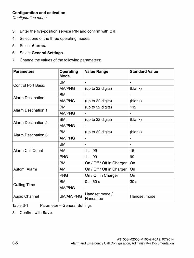
7. Change the values of the following parameters:
Table 3-1 Parameter – General Settings
Parameters Operating Mode
Value Range Standard Value
Control Port BasicBM - -
AM/PNG (up to 32 digits) (blank)
Alarm DestinationBM - -
AM/PNG (up to 32 digits) (blank)
Alarm Destination 1BM (up to 32 digits) 112
AM/PNG - -
Alarm Destination 2BM (up to 32 digits) (blank)
AM/PNG - -
Alarm Destination 3BM (up to 32 digits) (blank)
AM/PNG - -
Alarm Call Count
BM - -
AM 1 ... 99 15
PNG 1 ... 99 99
Autom. Alarm
BM On / Off / Off in Charger On
AM On / Off / Off in Charger On
PNG On / Off in Charger On
Calling TimeBM 0 ... 60 s 30 s
AM/PNG - -
Audio Channel BM/AM/PNGHandset mode / Handsfree
Handset mode
8. Confirm with Save.
A31003-M2000-M103-2-76A9, 07/20143-5 Alarm and Emergency Call Configuration, Administrator Documentation
SHB_PNG-Konfig.fm
Configuration and activationConfiguration menu
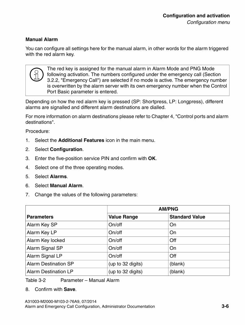
Manual Alarm
>
You can configure all settings here for the manual alarm, in other words for the alarm triggered with the red alarm key.
Depending on how the red alarm key is pressed (SP: Shortpress, LP: Longpress), different alarms are signalled and different alarm destinations are dialled.
For more information on alarm destinations please refer to Chapter 4, "Control ports and alarm destinations".
Procedure:
1. Select the Additional Features icon in the main menu.
2. Select Configuration.
3. Enter the five-position service PIN and confirm with OK.
4. Select one of the three operating modes.
5. Select Alarms.
6. Select Manual Alarm.
7. Change the values of the following parameters:
Table 3-2 Parameter – Manual Alarm
AM/PNG
Parameters Value Range Standard Value
Alarm Key SP On/off On
Alarm Key LP On/off On
Alarm Key locked On/off Off
Alarm Signal SP On/off On
Alarm Signal LP On/off Off
Alarm Destination SP (up to 32 digits) (blank)
Alarm Destination LP (up to 32 digits) (blank)
8. Confirm with Save.
The red key is assigned for the manual alarm in Alarm Mode and PNG Mode following activation. The numbers configured under the emergency call (Section 3.2.2, "Emergency Call") are selected if no mode is active. The emergency number is overwritten by the alarm server with its own emergency number when the Control Port Basic parameter is entered.
A31003-M2000-M103-2-76A9, 07/2014Alarm and Emergency Call Configuration, Administrator Documentation 3-6
Configuration and activation
SHB_PNG-Konfig.fm
Configuration menu
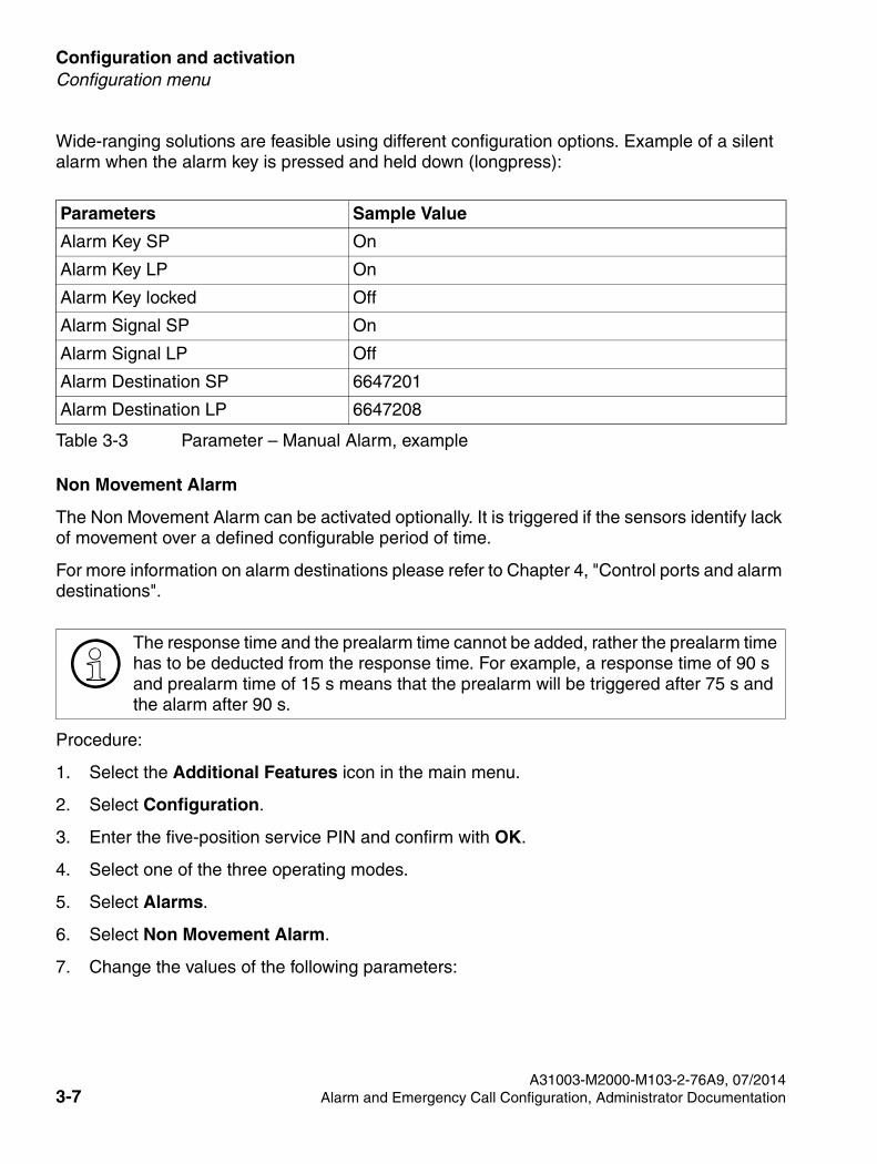
Table 3-3 Parameter – Manual Alarm, example
Parameters Sample Value
Alarm Key SP On
Alarm Key LP On
Alarm Key locked Off
Alarm Signal SP On
Alarm Signal LP Off
Alarm Destination SP 6647201
Alarm Destination LP 6647208
Wide-ranging solutions are feasible using different configuration options. Example of a silent alarm when the alarm key is pressed and held down (longpress):
Non Movement Alarm
>
The Non Movement Alarm can be activated optionally. It is triggered if the sensors identify lack of movement over a defined configurable period of time.
For more information on alarm destinations please refer to Chapter 4, "Control ports and alarm destinations".
Procedure:
1. Select the Additional Features icon in the main menu.
2. Select Configuration.
3. Enter the five-position service PIN and confirm with OK.
4. Select one of the three operating modes.
5. Select Alarms.
6. Select Non Movement Alarm.
7. Change the values of the following parameters:
The response time and the prealarm time cannot be added, rather the prealarm time has to be deducted from the response time. For example, a response time of 90 s and prealarm time of 15 s means that the prealarm will be triggered after 75 s and the alarm after 90 s.
A31003-M2000-M103-2-76A9, 07/20143-7 Alarm and Emergency Call Configuration, Administrator Documentation
SHB_PNG-Konfig.fm
Configuration and activationConfiguration menu
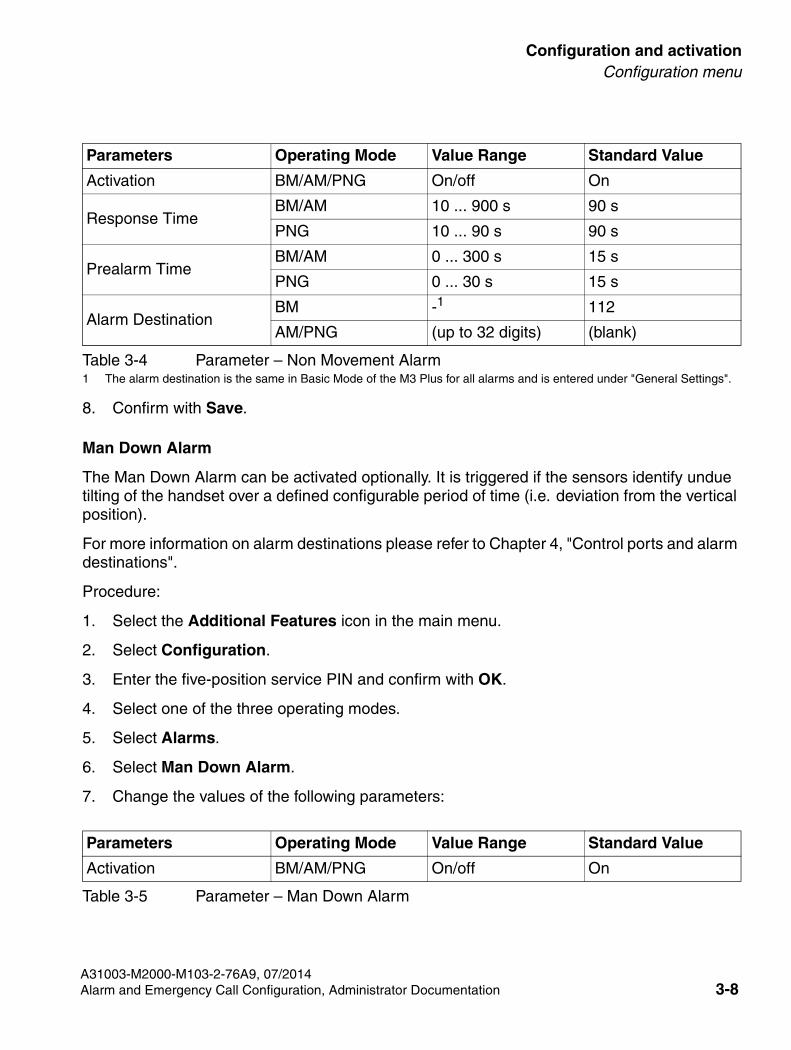
Table 3-4 Parameter – Non Movement Alarm
Parameters Operating Mode Value Range Standard Value
Activation BM/AM/PNG On/off On
Response TimeBM/AM 10 ... 900 s 90 s
PNG 10 ... 90 s 90 s
Prealarm TimeBM/AM 0 ... 300 s 15 s
PNG 0 ... 30 s 15 s
Alarm DestinationBM -1
1 The alarm destination is the same in Basic Mode of the M3 Plus for all alarms and is entered under "General Settings".
112
AM/PNG (up to 32 digits) (blank)
8. Confirm with Save.
Man Down Alarm
The Man Down Alarm can be activated optionally. It is triggered if the sensors identify undue tilting of the handset over a defined configurable period of time (i.e. deviation from the vertical position).
For more information on alarm destinations please refer to Chapter 4, "Control ports and alarm destinations".
Procedure:
1. Select the Additional Features icon in the main menu.
2. Select Configuration.
3. Enter the five-position service PIN and confirm with OK.
4. Select one of the three operating modes.
5. Select Alarms.
6. Select Man Down Alarm.
7. Change the values of the following parameters:
Parameters Operating Mode Value Range Standard Value
Activation BM/AM/PNG On/off On
Table 3-5 Parameter – Man Down Alarm
A31003-M2000-M103-2-76A9, 07/2014Alarm and Emergency Call Configuration, Administrator Documentation 3-8
Configuration and activation
SHB_PNG-Konfig.fm
Configuration menu
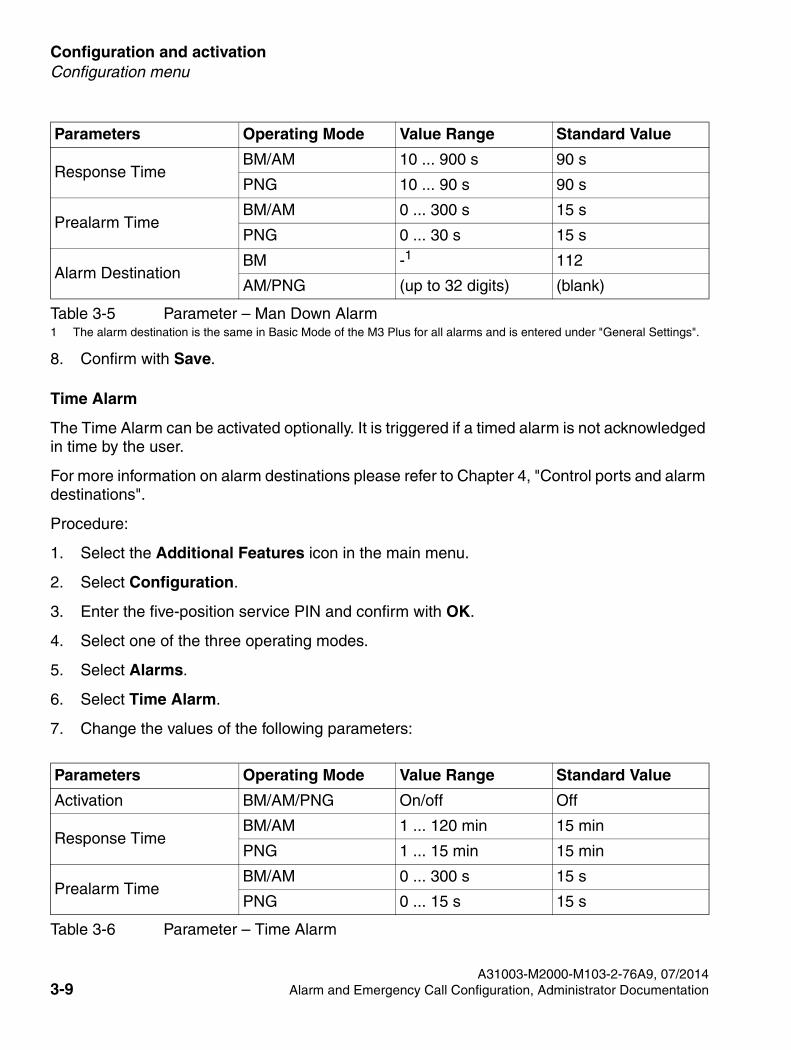
8. Confirm with Save.
Time Alarm
The Time Alarm can be activated optionally. It is triggered if a timed alarm is not acknowledged in time by the user.
For more information on alarm destinations please refer to Chapter 4, "Control ports and alarm destinations".
Procedure:
1. Select the Additional Features icon in the main menu.
2. Select Configuration.
3. Enter the five-position service PIN and confirm with OK.
4. Select one of the three operating modes.
5. Select Alarms.
6. Select Time Alarm.
7. Change the values of the following parameters:
Response TimeBM/AM 10 ... 900 s 90 s
PNG 10 ... 90 s 90 s
Prealarm TimeBM/AM 0 ... 300 s 15 s
PNG 0 ... 30 s 15 s
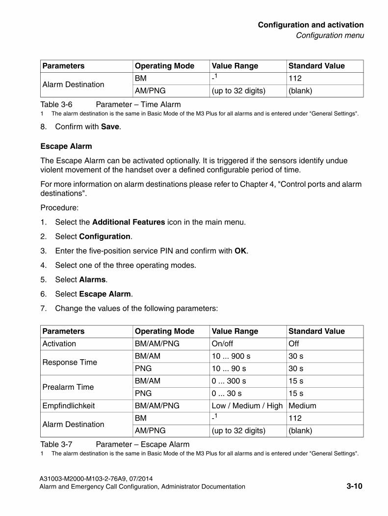
Alarm DestinationBM -1 112
AM/PNG (up to 32 digits) (blank)
1 The alarm destination is the same in Basic Mode of the M3 Plus for all alarms and is entered under "General Settings".
Parameters Operating Mode Value Range Standard Value
Activation BM/AM/PNG On/off Off
Response TimeBM/AM 1 ... 120 min 15 min
PNG 1 ... 15 min 15 min
Prealarm TimeBM/AM 0 ... 300 s 15 s
PNG 0 ... 15 s 15 s
Table 3-6 Parameter – Time Alarm
Parameters Operating Mode Value Range Standard Value
Table 3-5 Parameter – Man Down Alarm
A31003-M2000-M103-2-76A9, 07/20143-9 Alarm and Emergency Call Configuration, Administrator Documentation
SHB_PNG-Konfig.fm
Configuration and activationConfiguration menu
8. Confirm with Save.
Escape Alarm
The Escape Alarm can be activated optionally. It is triggered if the sensors identify undue violent movement of the handset over a defined configurable period of time.
For more information on alarm destinations please refer to Chapter 4, "Control ports and alarm destinations".
Procedure:
1. Select the Additional Features icon in the main menu.
2. Select Configuration.
3. Enter the five-position service PIN and confirm with OK.
4. Select one of the three operating modes.
5. Select Alarms.
6. Select Escape Alarm.
7. Change the values of the following parameters:
Table 3-7 Parameter – Escape Alarm
Parameters Operating Mode Value Range Standard Value
Activation BM/AM/PNG On/off Off
Response TimeBM/AM 10 ... 900 s 30 s
PNG 10 ... 90 s 30 s
Prealarm TimeBM/AM 0 ... 300 s 15 s
PNG 0 ... 30 s 15 s
Empfindlichkeit BM/AM/PNG Low / Medium / High Medium
Alarm DestinationBM -1
1 The alarm destination is the same in Basic Mode of the M3 Plus for all alarms and is entered under "General Settings".
112
AM/PNG (up to 32 digits) (blank)
Alarm DestinationBM -1 112
AM/PNG (up to 32 digits) (blank)
1 The alarm destination is the same in Basic Mode of the M3 Plus for all alarms and is entered under "General Settings".
Parameters Operating Mode Value Range Standard Value
Table 3-6 Parameter – Time Alarm
A31003-M2000-M103-2-76A9, 07/2014Alarm and Emergency Call Configuration, Administrator Documentation 3-10
Configuration and activation
SHB_PNG-Konfig.fm
Configuration menu
8. Confirm with Save.
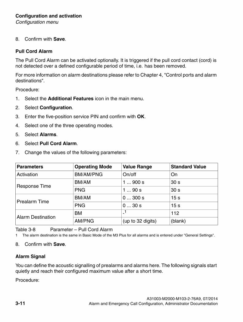
Pull Cord Alarm
The Pull Cord Alarm can be activated optionally. It is triggered if the pull cord contact (cord) is not detected over a defined configurable period of time, i.e. has been removed.
For more information on alarm destinations please refer to Chapter 4, "Control ports and alarm destinations".
Procedure:
1. Select the Additional Features icon in the main menu.
2. Select Configuration.
3. Enter the five-position service PIN and confirm with OK.
4. Select one of the three operating modes.
5. Select Alarms.
6. Select Pull Cord Alarm.
7. Change the values of the following parameters:
Table 3-8 Parameter – Pull Cord Alarm
Parameters Operating Mode Value Range Standard Value
Activation BM/AM/PNG On/off On
Response TimeBM/AM 1 ... 900 s 30 s
PNG 1 ... 90 s 30 s
Prealarm TimeBM/AM 0 ... 300 s 15 s
PNG 0 ... 30 s 15 s
Alarm DestinationBM -1
1 The alarm destination is the same in Basic Mode of the M3 Plus for all alarms and is entered under "General Settings".
112
AM/PNG (up to 32 digits) (blank)
8. Confirm with Save.
Alarm Signal
You can define the acoustic signalling of prealarms and alarms here. The following signals start quietly and reach their configured maximum value after a short time.
Procedure:
A31003-M2000-M103-2-76A9, 07/20143-11 Alarm and Emergency Call Configuration, Administrator Documentation
SHB_PNG-Konfig.fm
Configuration and activationConfiguration menu
1. Select the Additional Features icon in the main menu.
2. Select Configuration.
3. Enter the five-position service PIN and confirm with OK.
4. Select one of the three operating modes.
5. Select Alarms.
6. Select Alarm Signal.
7. Select Prealarm or Alarming Signal.
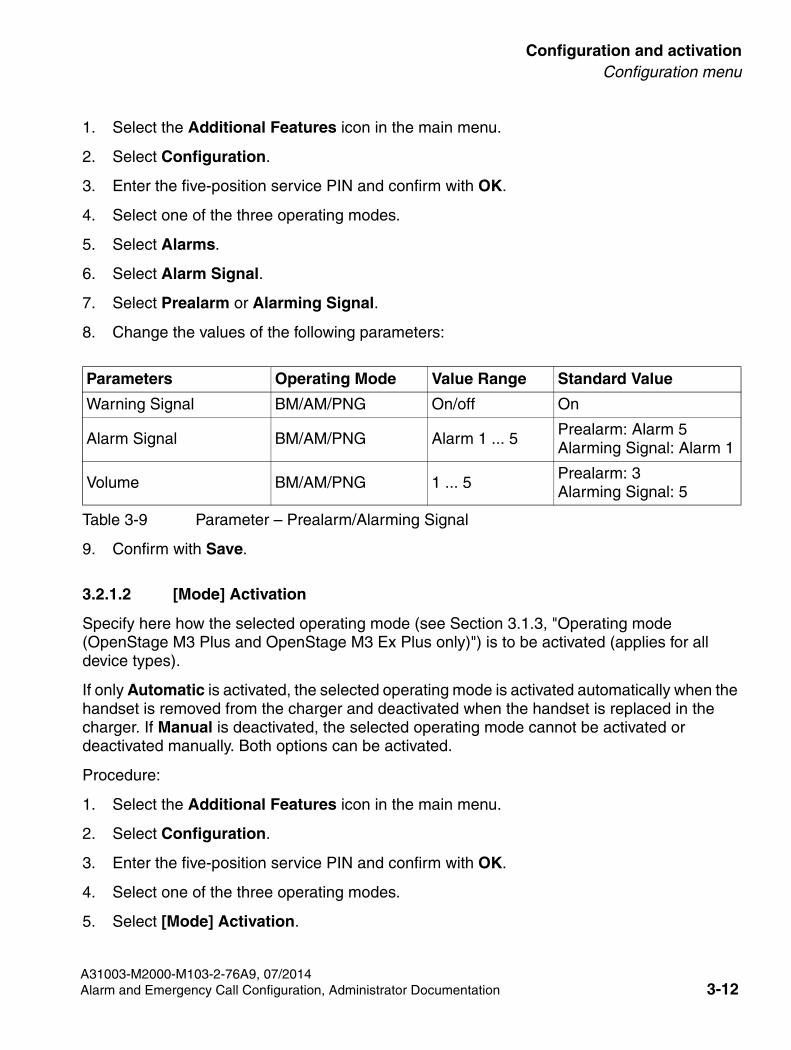
8. Change the values of the following parameters:
Table 3-9 Parameter – Prealarm/Alarming Signal
Parameters Operating Mode Value Range Standard Value
Warning Signal BM/AM/PNG On/off On
Alarm Signal BM/AM/PNG Alarm 1 ... 5Prealarm: Alarm 5Alarming Signal: Alarm 1
Volume BM/AM/PNG 1 ... 5Prealarm: 3Alarming Signal: 5
9. Confirm with Save.
3.2.1.2 [Mode] Activation
Specify here how the selected operating mode (see Section 3.1.3, "Operating mode (OpenStage M3 Plus and OpenStage M3 Ex Plus only)") is to be activated (applies for all device types).
If only Automatic is activated, the selected operating mode is activated automatically when the handset is removed from the charger and deactivated when the handset is replaced in the charger. If Manual is deactivated, the selected operating mode cannot be activated or deactivated manually. Both options can be activated.
Procedure:
1. Select the Additional Features icon in the main menu.
2. Select Configuration.
3. Enter the five-position service PIN and confirm with OK.
4. Select one of the three operating modes.
5. Select [Mode] Activation.
A31003-M2000-M103-2-76A9, 07/2014Alarm and Emergency Call Configuration, Administrator Documentation 3-12
Configuration and activation
SHB_PNG-Konfig.fm
Configuration menu
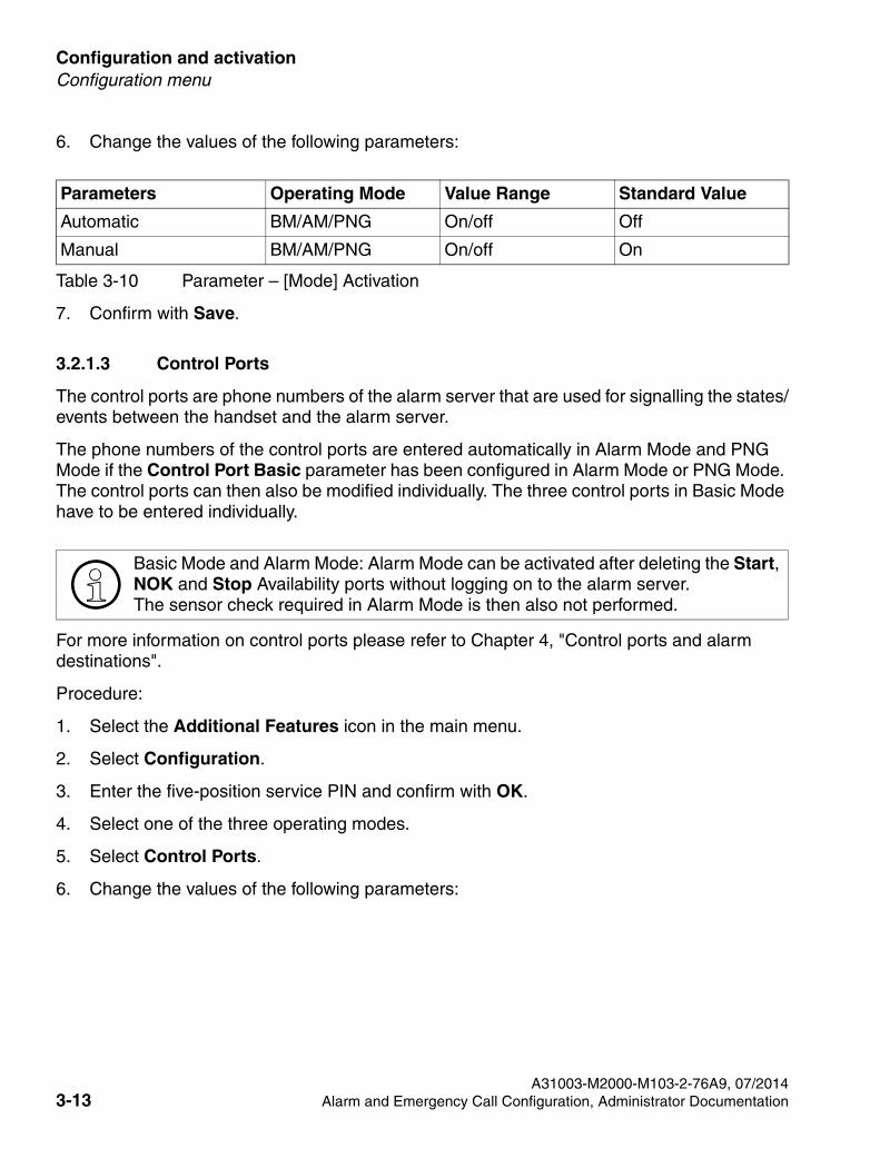
6. Change the values of the following parameters:
Table 3-10 Parameter – [Mode] Activation
Parameters Operating Mode Value Range Standard Value
Automatic BM/AM/PNG On/off Off
Manual BM/AM/PNG On/off On
7. Confirm with Save.
3.2.1.3 Control Ports
>Basic Mode and Alarm Mode: Alarm Mode can be activated after deleting the Start, NOK and Stop Availability ports without logging on to the alarm server. The sensor check required in Alarm Mode is then also not performed.
The control ports are phone numbers of the alarm server that are used for signalling the states/events between the handset and the alarm server.
The phone numbers of the control ports are entered automatically in Alarm Mode and PNG Mode if the Control Port Basic parameter has been configured in Alarm Mode or PNG Mode. The control ports can then also be modified individually. The three control ports in Basic Mode have to be entered individually.
For more information on control ports please refer to Chapter 4, "Control ports and alarm destinations".
Procedure:
1. Select the Additional Features icon in the main menu.
2. Select Configuration.
3. Enter the five-position service PIN and confirm with OK.
4. Select one of the three operating modes.
5. Select Control Ports.
6. Change the values of the following parameters:
A31003-M2000-M103-2-76A9, 07/20143-13 Alarm and Emergency Call Configuration, Administrator Documentation
SHB_PNG-Konfig.fm
Configuration and activationConfiguration menu
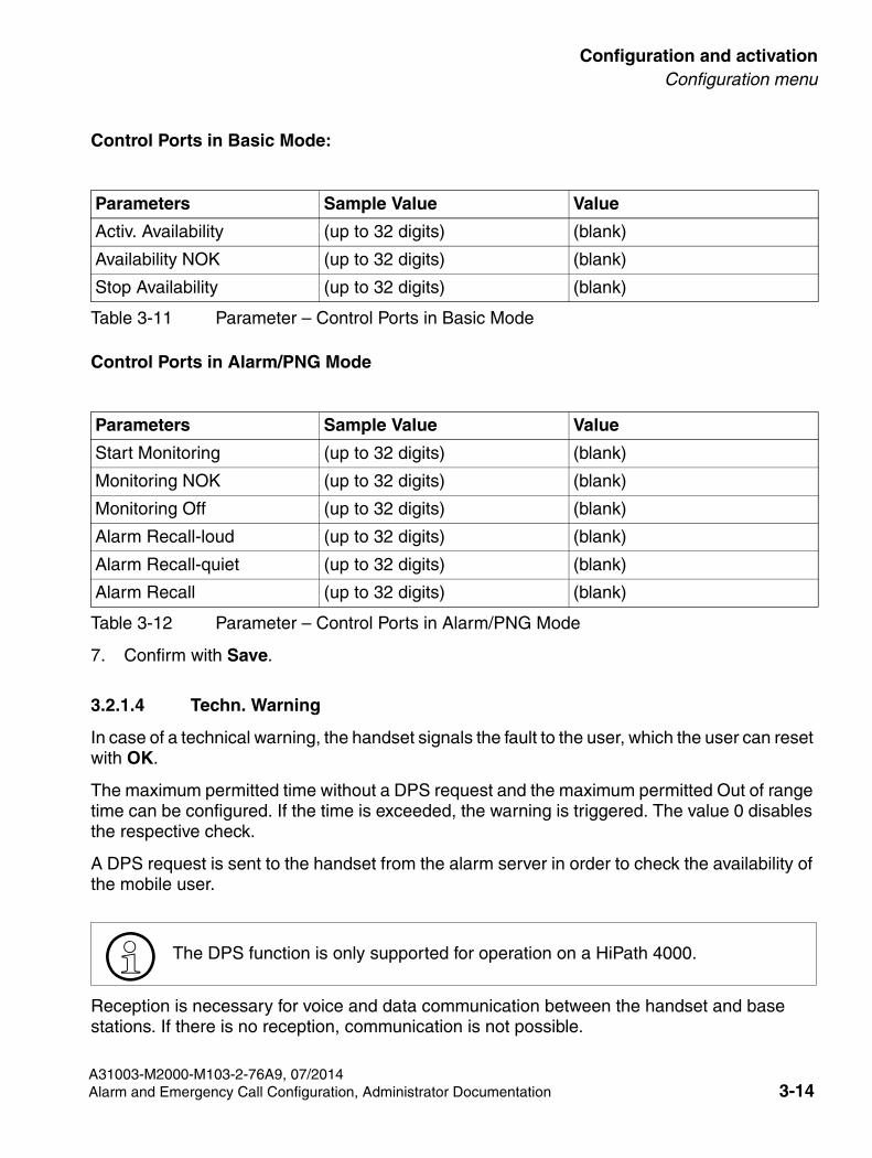
Control Ports in Basic Mode:
Table 3-11 Parameter – Control Ports in Basic Mode
Parameters Sample Value Value
Activ. Availability (up to 32 digits) (blank)
Availability NOK (up to 32 digits) (blank)
Stop Availability (up to 32 digits) (blank)
Control Ports in Alarm/PNG Mode
Table 3-12 Parameter – Control Ports in Alarm/PNG Mode
Parameters Sample Value Value
Start Monitoring (up to 32 digits) (blank)
Monitoring NOK (up to 32 digits) (blank)
Monitoring Off (up to 32 digits) (blank)
Alarm Recall-loud (up to 32 digits) (blank)
Alarm Recall-quiet (up to 32 digits) (blank)
Alarm Recall (up to 32 digits) (blank)
7. Confirm with Save.
3.2.1.4 Techn. Warning
> The DPS function is only supported for operation on a HiPath 4000.
In case of a technical warning, the handset signals the fault to the user, which the user can reset with OK.
The maximum permitted time without a DPS request and the maximum permitted Out of range time can be configured. If the time is exceeded, the warning is triggered. The value 0 disables the respective check.
A DPS request is sent to the handset from the alarm server in order to check the availability of the mobile user.
Reception is necessary for voice and data communication between the handset and base stations. If there is no reception, communication is not possible.
A31003-M2000-M103-2-76A9, 07/2014Alarm and Emergency Call Configuration, Administrator Documentation 3-14
Configuration and activation
SHB_PNG-Konfig.fm
Configuration menu
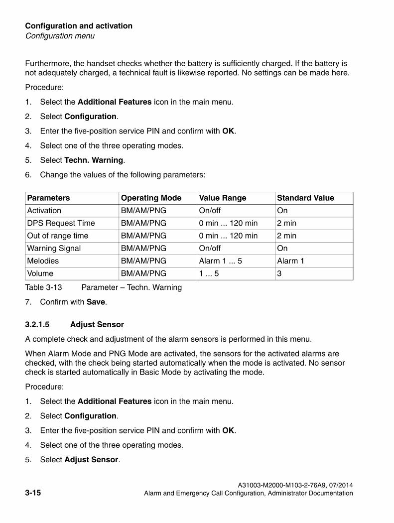
Furthermore, the handset checks whether the battery is sufficiently charged. If the battery is not adequately charged, a technical fault is likewise reported. No settings can be made here.
Procedure:
1. Select the Additional Features icon in the main menu.
2. Select Configuration.
3. Enter the five-position service PIN and confirm with OK.
4. Select one of the three operating modes.
5. Select Techn. Warning.
6. Change the values of the following parameters:
Table 3-13 Parameter – Techn. Warning
Parameters Operating Mode Value Range Standard Value
Activation BM/AM/PNG On/off On
DPS Request Time BM/AM/PNG 0 min ... 120 min 2 min
Out of range time BM/AM/PNG 0 min ... 120 min 2 min
Warning Signal BM/AM/PNG On/off On
Melodies BM/AM/PNG Alarm 1 ... 5 Alarm 1
Volume BM/AM/PNG 1 ... 5 3
7. Confirm with Save.
3.2.1.5 Adjust Sensor
A complete check and adjustment of the alarm sensors is performed in this menu.
When Alarm Mode and PNG Mode are activated, the sensors for the activated alarms are checked, with the check being started automatically when the mode is activated. No sensor check is started automatically in Basic Mode by activating the mode.
Procedure:
1. Select the Additional Features icon in the main menu.
2. Select Configuration.
3. Enter the five-position service PIN and confirm with OK.
4. Select one of the three operating modes.
5. Select Adjust Sensor.
A31003-M2000-M103-2-76A9, 07/20143-15 Alarm and Emergency Call Configuration, Administrator Documentation
SHB_PNG-Konfig.fm
Configuration and activationConfiguration menu
6. Keep the handset still in a vertical position and confirm with OK.
7. Shake the handset vigorously until the test is successful.
8. Keep the handset still in a vertical position until the test is successful.
9. Press the red alarm key at the top of the handset.
10. Remove the connector with the pull cord from the socket at the lower end of the handset and insert it again.
> If the function test fails repeatedly, shut down the phone immediately and send it to the manufacturer.
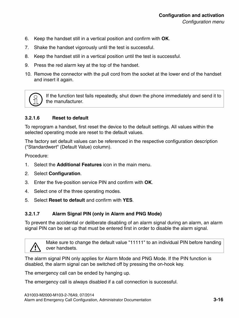
3.2.1.6 Reset to default
To reprogram a handset, first reset the device to the default settings. All values within the selected operating mode are reset to the default values.
The factory set default values can be referenced in the respective configuration description ("Standardwert" (Default Value) column).
Procedure:
1. Select the Additional Features icon in the main menu.
2. Select Configuration.
3. Enter the five-position service PIN and confirm with OK.
4. Select one of the three operating modes.
5. Select Reset to default and confirm with YES.
3.2.1.7 Alarm Signal PIN (only in Alarm and PNG Mode)
7Make sure to change the default value "11111" to an individual PIN before handing over handsets.
To prevent the accidental or deliberate disabling of an alarm signal during an alarm, an alarm signal PIN can be set up that must be entered first in order to disable the alarm signal.
The alarm signal PIN only applies for Alarm Mode and PNG Mode. If the PIN function is disabled, the alarm signal can be switched off by pressing the on-hook key.
The emergency call can be ended by hanging up.
The emergency call is always disabled if a call connection is successful.
A31003-M2000-M103-2-76A9, 07/2014Alarm and Emergency Call Configuration, Administrator Documentation 3-16
Configuration and activation
SHB_PNG-Konfig.fm
Configuration menu
Procedure:
1. Select the Additional Features icon in the main menu.
2. Select Configuration.
3. Enter the five-position service PIN and confirm with OK.
4. Select one of the three operating modes.
5. Select Alarm Signal PIN.
6. Change the values of the following parameters:
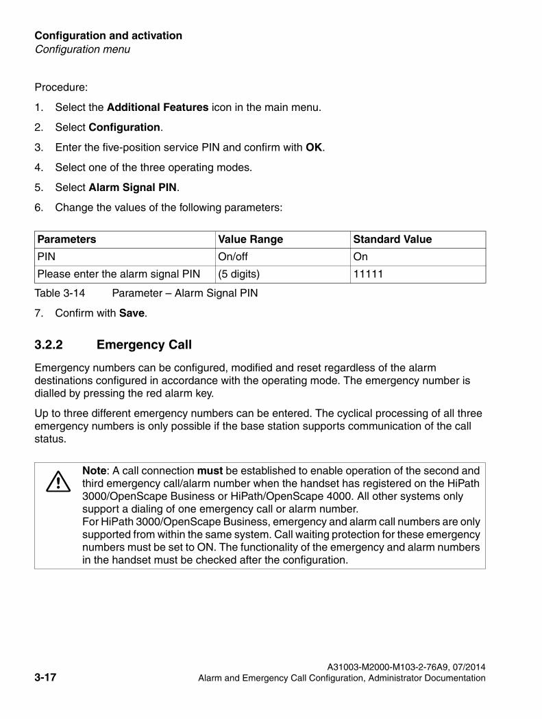
Table 3-14 Parameter – Alarm Signal PIN
Parameters Value Range Standard Value
PIN On/off On
Please enter the alarm signal PIN (5 digits) 11111
7. Confirm with Save.
3.2.2 Emergency Call
7Note: A call connection must be established to enable operation of the second and third emergency call/alarm number when the handset has registered on the HiPath 3000/OpenScape Business or HiPath/OpenScape 4000. All other systems only support a dialing of one emergency call or alarm number.For HiPath 3000/OpenScape Business, emergency and alarm call numbers are only supported from within the same system. Call waiting protection for these emergency numbers must be set to ON. The functionality of the emergency and alarm numbers in the handset must be checked after the configuration.
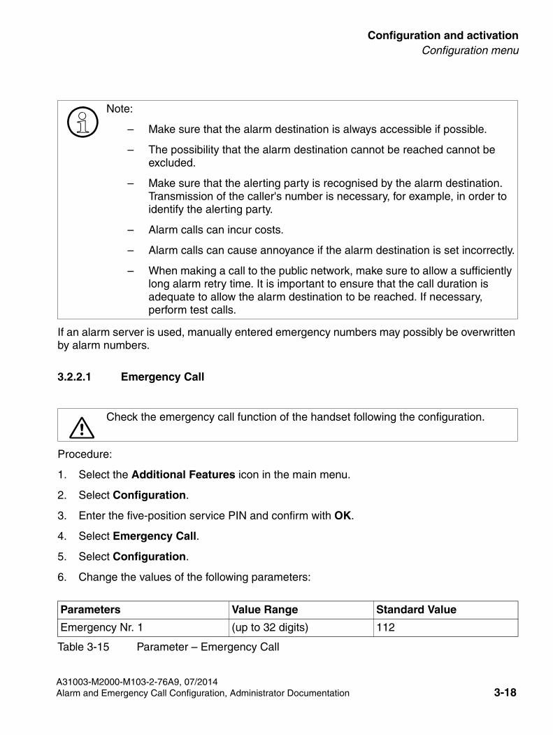
Emergency numbers can be configured, modified and reset regardless of the alarm destinations configured in accordance with the operating mode. The emergency number is dialled by pressing the red alarm key.
Up to three different emergency numbers can be entered. The cyclical processing of all three emergency numbers is only possible if the base station supports communication of the call status.
A31003-M2000-M103-2-76A9, 07/20143-17 Alarm and Emergency Call Configuration, Administrator Documentation
SHB_PNG-Konfig.fm
Configuration and activationConfiguration menu
>Note:
– Make sure that the alarm destination is always accessible if possible.
– The possibility that the alarm destination cannot be reached cannot be excluded.
– Make sure that the alerting party is recognised by the alarm destination. Transmission of the caller's number is necessary, for example, in order to identify the alerting party.
– Alarm calls can incur costs.
– Alarm calls can cause annoyance if the alarm destination is set incorrectly.
– When making a call to the public network, make sure to allow a sufficiently long alarm retry time. It is important to ensure that the call duration is adequate to allow the alarm destination to be reached. If necessary, perform test calls.
If an alarm server is used, manually entered emergency numbers may possibly be overwritten by alarm numbers.
3.2.2.1 Emergency Call
7Check the emergency call function of the handset following the configuration.
Procedure:
1. Select the Additional Features icon in the main menu.
2. Select Configuration.
3. Enter the five-position service PIN and confirm with OK.
4. Select Emergency Call.
5. Select Configuration.
6. Change the values of the following parameters:
Parameters Value Range Standard Value
Emergency Nr. 1 (up to 32 digits) 112
Table 3-15 Parameter – Emergency Call
A31003-M2000-M103-2-76A9, 07/2014Alarm and Emergency Call Configuration, Administrator Documentation 3-18
Configuration and activation
SHB_PNG-Konfig.fm
Configuration menu
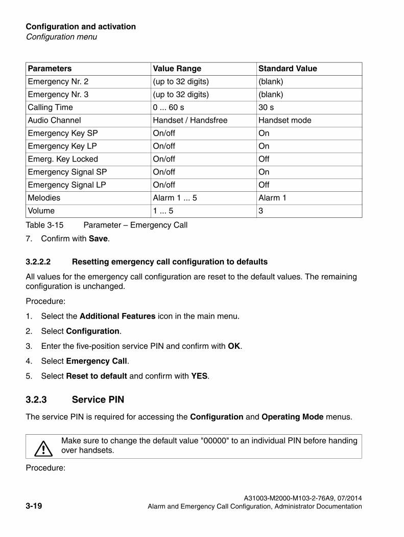
7. Confirm with Save.
3.2.2.2 Resetting emergency call configuration to defaults
All values for the emergency call configuration are reset to the default values. The remaining configuration is unchanged.
Procedure:
1. Select the Additional Features icon in the main menu.
2. Select Configuration.
3. Enter the five-position service PIN and confirm with OK.
4. Select Emergency Call.
5. Select Reset to default and confirm with YES.
3.2.3 Service PIN
The service PIN is required for accessing the Configuration and Operating Mode menus.
7Make sure to change the default value "00000" to an individual PIN before handing over handsets.
Procedure:
Emergency Nr. 2 (up to 32 digits) (blank)
Emergency Nr. 3 (up to 32 digits) (blank)
Calling Time 0 ... 60 s 30 s
Audio Channel Handset / Handsfree Handset mode
Emergency Key SP On/off On
Emergency Key LP On/off On
Emerg. Key Locked On/off Off
Emergency Signal SP On/off On
Emergency Signal LP On/off Off
Melodies Alarm 1 ... 5 Alarm 1
Volume 1 ... 5 3
Parameters Value Range Standard Value
Table 3-15 Parameter – Emergency Call
A31003-M2000-M103-2-76A9, 07/20143-19 Alarm and Emergency Call Configuration, Administrator Documentation
SHB_PNG-Konfig.fm
Configuration and activationConfiguration menu
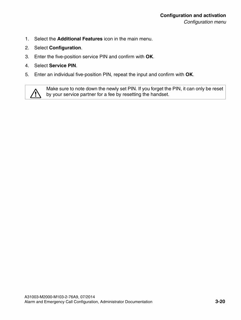
1. Select the Additional Features icon in the main menu.
2. Select Configuration.
3. Enter the five-position service PIN and confirm with OK.
4. Select Service PIN.
5. Enter an individual five-position PIN, repeat the input and confirm with OK.
7Make sure to note down the newly set PIN. If you forget the PIN, it can only be reset by your service partner for a fee by resetting the handset.
A31003-M2000-M103-2-76A9, 07/2014Alarm and Emergency Call Configuration, Administrator Documentation 3-20
Configuration and activation
SHB_PNG-Konfig.fm
Exporting and transmitting the configuration
3.3 Exporting and transmitting the configuration
> The tool is available on the SWS.
The Firmware Update Tool can be used to export the configuration from devices in the M3 family and transfer it to other devices.
A31003-M2000-M103-2-76A9, 07/20143-21 Alarm and Emergency Call Configuration, Administrator Documentation
SHB_PNG-Ports.fm
Control ports and alarm destinationsSyntax of the control ports and alarm destinations
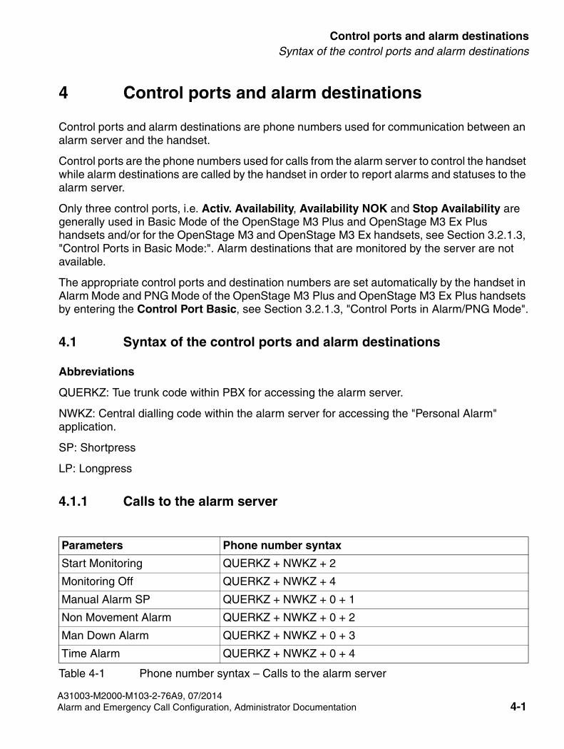
4 Control ports and alarm destinations
Control ports and alarm destinations are phone numbers used for communication between an alarm server and the handset.
Control ports are the phone numbers used for calls from the alarm server to control the handset while alarm destinations are called by the handset in order to report alarms and statuses to the alarm server.
Only three control ports, i.e. Activ. Availability, Availability NOK and Stop Availability are generally used in Basic Mode of the OpenStage M3 Plus and OpenStage M3 Ex Plus handsets and/or for the OpenStage M3 and OpenStage M3 Ex handsets, see Section 3.2.1.3, "Control Ports in Basic Mode:". Alarm destinations that are monitored by the server are not available.
The appropriate control ports and destination numbers are set automatically by the handset in Alarm Mode and PNG Mode of the OpenStage M3 Plus and OpenStage M3 Ex Plus handsets by entering the Control Port Basic, see Section 3.2.1.3, "Control Ports in Alarm/PNG Mode".
4.1 Syntax of the control ports and alarm destinations
Abbreviations
QUERKZ: Tue trunk code within PBX for accessing the alarm server.
NWKZ: Central dialling code within the alarm server for accessing the "Personal Alarm" application.
SP: Shortpress
LP: Longpress
4.1.1 Calls to the alarm server
Parameters Phone number syntax
Start Monitoring QUERKZ + NWKZ + 2
Monitoring Off QUERKZ + NWKZ + 4
Manual Alarm SP QUERKZ + NWKZ + 0 + 1
Non Movement Alarm QUERKZ + NWKZ + 0 + 2
Man Down Alarm QUERKZ + NWKZ + 0 + 3
Time Alarm QUERKZ + NWKZ + 0 + 4
Table 4-1 Phone number syntax – Calls to the alarm server
A31003-M2000-M103-2-76A9, 07/2014Alarm and Emergency Call Configuration, Administrator Documentation 4-1
Control ports and alarm destinations
SHB_PNG-Ports.fm
Example
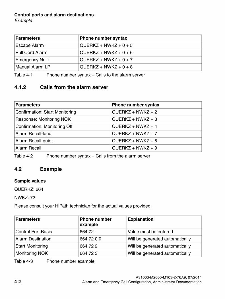
4.1.2 Calls from the alarm server
Table 4-2 Phone number syntax – Calls from the alarm server
Parameters Phone number syntax
Confirmation: Start Monitoring QUERKZ + NWKZ + 2
Response: Monitoring NOK QUERKZ + NWKZ + 3
Confirmation: Monitoring Off QUERKZ + NWKZ + 4
Alarm Recall-loud QUERKZ + NWKZ + 7
Alarm Recall-quiet QUERKZ + NWKZ + 8
Alarm Recall QUERKZ + NWKZ + 9
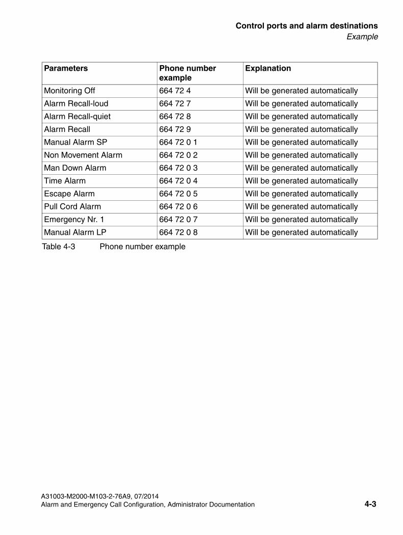
4.2 Example
Sample values
QUERKZ: 664
NWKZ: 72
Please consult your HiPath technician for the actual values provided.
Escape Alarm QUERKZ + NWKZ + 0 + 5
Pull Cord Alarm QUERKZ + NWKZ + 0 + 6
Emergency Nr. 1 QUERKZ + NWKZ + 0 + 7
Manual Alarm LP QUERKZ + NWKZ + 0 + 8
Parameters Phone number example
Explanation
Control Port Basic 664 72 Value must be entered
Alarm Destination 664 72 0 0 Will be generated automatically
Start Monitoring 664 72 2 Will be generated automatically
Monitoring NOK 664 72 3 Will be generated automatically
Table 4-3 Phone number example
Parameters Phone number syntax
Table 4-1 Phone number syntax – Calls to the alarm server
A31003-M2000-M103-2-76A9, 07/20144-2 Alarm and Emergency Call Configuration, Administrator Documentation
SHB_PNG-Ports.fm
Control ports and alarm destinationsExample
Monitoring Off 664 72 4 Will be generated automatically
Alarm Recall-loud 664 72 7 Will be generated automatically
Alarm Recall-quiet 664 72 8 Will be generated automatically
Alarm Recall 664 72 9 Will be generated automatically
Manual Alarm SP 664 72 0 1 Will be generated automatically
Non Movement Alarm 664 72 0 2 Will be generated automatically
Man Down Alarm 664 72 0 3 Will be generated automatically
Time Alarm 664 72 0 4 Will be generated automatically
Escape Alarm 664 72 0 5 Will be generated automatically
Pull Cord Alarm 664 72 0 6 Will be generated automatically
Emergency Nr. 1 664 72 0 7 Will be generated automatically
Manual Alarm LP 664 72 0 8 Will be generated automatically
Parameters Phone number example
Explanation
Table 4-3 Phone number example
A31003-M2000-M103-2-76A9, 07/2014Alarm and Emergency Call Configuration, Administrator Documentation 4-3
SHB_PNG-Check.fm
A31003-M2000-M103-2-76A9, 07/2014Alarm and Emergency Call Configuration, Administrator Documentation 5-1
Response times under VDE 0825
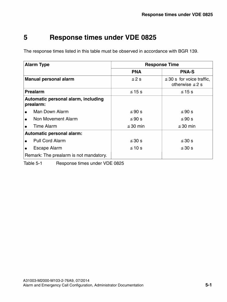
5 Response times under VDE 0825
Table 5-1 Response times under VDE 0825
Alarm Type Response Time
PNA PNA-S
Manual personal alarm 2 s 30 s for voice traffic, otherwise 2 s
Prealarm 15 s 15 s
Automatic personal alarm, including prealarm:
● Man Down Alarm 90 s 90 s
● Non Movement Alarm 90 s 90 s
● Time Alarm 30 min 30 min
Automatic personal alarm:
● Pull Cord Alarm 30 s 30 s
● Escape Alarm 10 s 30 s
Remark: The prealarm is not mandatory.
The response times listed in this table must be observed in accordance with BGR 139.
SHB_PNG-Menu.fm
Structure of the Additional Features menuOpenStage M3/OpenStage M3 Ex
A31003-M2000-M103-2-76A9, 07/2014
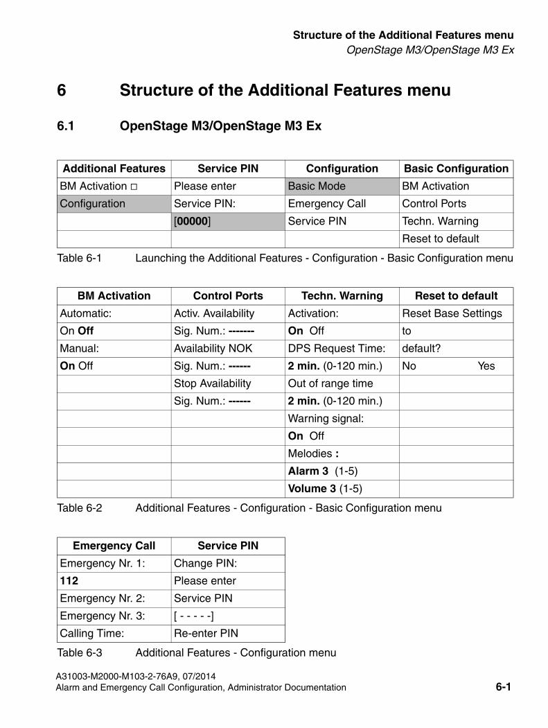
6 Structure of the Additional Features menu
6.1 OpenStage M3/OpenStage M3 Ex
Table 6-1 Launching the Additional Features - Configuration - Basic Configuration menu
Additional Features Service PIN Configuration Basic Configuration
BM Activation Please enter Basic Mode BM Activation
Configuration Service PIN: Emergency Call Control Ports
[00000] Service PIN Techn. Warning
Reset to default
Table 6-2 Additional Features - Configuration - Basic Configuration menu
BM Activation Control Ports Techn. Warning Reset to default
Automatic: Activ. Availability Activation: Reset Base Settings
On Off Sig. Num.: ------- On Off to
Manual: Availability NOK DPS Request Time: default?
On Off Sig. Num.: ------ 2 min. (0-120 min.) No Yes
Stop Availability Out of range time
Sig. Num.: ------ 2 min. (0-120 min.)
Warning signal:
On Off
Melodies :
Alarm 3 (1-5)
Volume 3 (1-5)
Emergency Call Service PIN
Emergency Nr. 1: Change PIN:
112 Please enter
Emergency Nr. 2: Service PIN
Emergency Nr. 3: [ - - - - -]
Calling Time: Re-enter PIN
Table 6-3 Additional Features - Configuration menu
Alarm and Emergency Call Configuration, Administrator Documentation 6-1
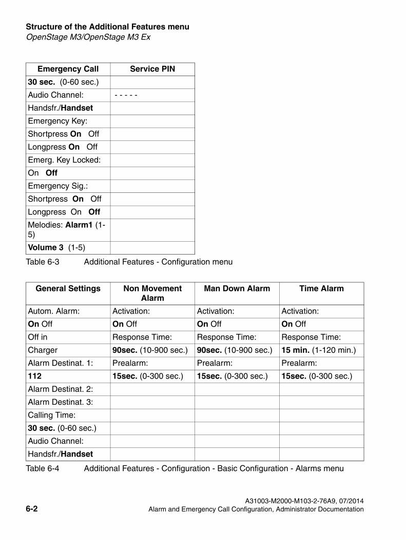
Structure of the Additional Features menu
SHB_PNG-Menu.fm
OpenStage M3/OpenStage M3 Ex
30 sec. (0-60 sec.)
Audio Channel: - - - - -
Handsfr./Handset
Emergency Key:
Shortpress On Off
Longpress On Off
Emerg. Key Locked:
On Off
Emergency Sig.:
Shortpress On Off
Longpress On Off
Melodies: Alarm1 (1-5)
Volume 3 (1-5)
Table 6-4 Additional Features - Configuration - Basic Configuration - Alarms menu
General Settings Non Movement Alarm
Man Down Alarm Time Alarm
Autom. Alarm: Activation: Activation: Activation:
On Off On Off On Off On Off
Off in Response Time: Response Time: Response Time:
Charger 90sec. (10-900 sec.) 90sec. (10-900 sec.) 15 min. (1-120 min.)
Alarm Destinat. 1: Prealarm: Prealarm: Prealarm:
112 15sec. (0-300 sec.) 15sec. (0-300 sec.) 15sec. (0-300 sec.)
Alarm Destinat. 2:
Alarm Destinat. 3:
Calling Time:
30 sec. (0-60 sec.)
Audio Channel:
Handsfr./Handset
Emergency Call Service PIN
Table 6-3 Additional Features - Configuration menu
A31003-M2000-M103-2-76A9, 07/20146-2 Alarm and Emergency Call Configuration, Administrator Documentation
SHB_PNG-Menu.fm
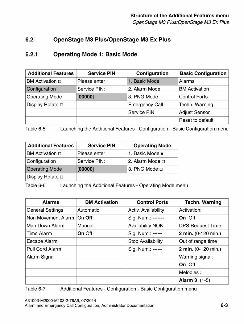
Structure of the Additional Features menuOpenStage M3 Plus/OpenStage M3 Ex Plus
6.2 OpenStage M3 Plus/OpenStage M3 Ex Plus
6.2.1 Operating Mode 1: Basic Mode
Table 6-5 Launching the Additional Features - Configuration - Basic Configuration menu
Additional Features Service PIN Configuration Basic Configuration
BM Activation Please enter 1. Basic Mode Alarms
Configuration Service PIN: 2. Alarm Mode BM Activation
Operating Mode [00000] 3. PNG Mode Control Ports
Display Rotate Emergency Call Techn. Warning
Service PIN Adjust Sensor
Reset to default
Table 6-6 Launching the Additional Features - Operating Mode menu
Additional Features Service PIN Operating Mode
BM Activation Please enter 1. Basic Mode
Configuration Service PIN: 2. Alarm Mode
Operating Mode [00000] 3. PNG Mode
Display Rotate
Alarms BM Activation Control Ports Techn. Warning
General Settings Automatic: Activ. Availability Activation:
Non Movement Alarm On Off Sig. Num.: ------- On Off
Man Down Alarm Manual: Availability NOK DPS Request Time:
Time Alarm On Off Sig. Num.: ------ 2 min. (0-120 min.)
Escape Alarm Stop Availability Out of range time
Pull Cord Alarm Sig. Num.: ------ 2 min. (0-120 min.)
Alarm Signal Warning signal:
On Off
Melodies :
Alarm 3 (1-5)
Table 6-7 Additional Features - Configuration - Basic Configuration menu
A31003-M2000-M103-2-76A9, 07/2014Alarm and Emergency Call Configuration, Administrator Documentation 6-3
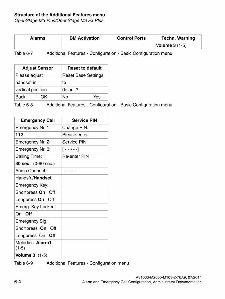
Structure of the Additional Features menu
SHB_PNG-Menu.fm
OpenStage M3 Plus/OpenStage M3 Ex Plus
Volume 3 (1-5)
Table 6-8 Additional Features - Configuration - Basic Configuration menu
Adjust Sensor Reset to default
Please adjust Reset Base Settings
handset in to
vertical position default?
Back OK No Yes
Table 6-9 Additional Features - Configuration menu
Emergency Call Service PIN
Emergency Nr. 1: Change PIN:
112 Please enter
Emergency Nr. 2: Service PIN
Emergency Nr. 3: [ - - - - -]
Calling Time: Re-enter PIN
30 sec. (0-60 sec.)
Audio Channel: - - - - -
Handsfr./Handset
Emergency Key:
Shortpress On Off
Longpress On Off
Emerg. Key Locked:
On Off
Emergency Sig.:
Shortpress On Off
Longpress On Off
Melodies: Alarm1 (1-5)
Volume 3 (1-5)
Alarms BM Activation Control Ports Techn. Warning
Table 6-7 Additional Features - Configuration - Basic Configuration menu
A31003-M2000-M103-2-76A9, 07/20146-4 Alarm and Emergency Call Configuration, Administrator Documentation
SHB_PNG-Menu.fm
Structure of the Additional Features menuOpenStage M3 Plus/OpenStage M3 Ex Plus
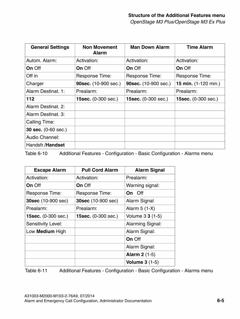
Table 6-10 Additional Features - Configuration - Basic Configuration - Alarms menu
General Settings Non Movement Alarm
Man Down Alarm Time Alarm
Autom. Alarm: Activation: Activation: Activation:
On Off On Off On Off On Off
Off in Response Time: Response Time: Response Time:
Charger 90sec. (10-900 sec.) 90sec. (10-900 sec.) 15 min. (1-120 min.)
Alarm Destinat. 1: Prealarm: Prealarm: Prealarm:
112 15sec. (0-300 sec.) 15sec. (0-300 sec.) 15sec. (0-300 sec.)
Alarm Destinat. 2:
Alarm Destinat. 3:
Calling Time:
30 sec. (0-60 sec.)
Audio Channel:
Handsfr./Handset
Table 6-11 Additional Features - Configuration - Basic Configuration - Alarms menu
Escape Alarm Pull Cord Alarm Alarm Signal
Activation: Activation: Prealarm:
On Off On Off Warning signal:
Response Time: Response Time: On Off
30sec (10-900 sec) 30sec (10-900 sec) Alarm Signal
Prealarm: Prealarm: Alarm 5 (1-X)
15sec. (0-300 sec.) 15sec. (0-300 sec.) Volume 3 3 (1-5)
Sensitivity Level: Alarming Signal:
Low Medium High Alarm Signal:
On Off
Alarm Signal:
Alarm 2 (1-5)
Volume 3 (1-5)
A31003-M2000-M103-2-76A9, 07/2014Alarm and Emergency Call Configuration, Administrator Documentation 6-5
Structure of the Additional Features menu
SHB_PNG-Menu.fm
OpenStage M3 Plus/OpenStage M3 Ex Plus
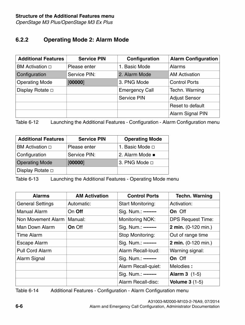
6.2.2 Operating Mode 2: Alarm Mode
Table 6-12 Launching the Additional Features - Configuration - Alarm Configuration menu
Additional Features Service PIN Configuration Alarm Configuration
BM Activation Please enter 1. Basic Mode Alarms
Configuration Service PIN: 2. Alarm Mode AM Activation
Operating Mode [00000] 3. PNG Mode Control Ports
Display Rotate Emergency Call Techn. Warning
Service PIN Adjust Sensor
Reset to default
Alarm Signal PIN
Table 6-13 Launching the Additional Features - Operating Mode menu
Additional Features Service PIN Operating Mode
BM Activation Please enter 1. Basic Mode
Configuration Service PIN: 2. Alarm Mode
Operating Mode [00000] 3. PNG Mode
Display Rotate
Alarms AM Activation Control Ports Techn. Warning
General Settings Automatic: Start Monitoring: Activation:
Manual Alarm On Off Sig. Num.: -------- On Off
Non Movement Alarm Manual: Monitoring NOK: DPS Request Time:
Man Down Alarm On Off Sig. Num.: -------- 2 min. (0-120 min.)
Time Alarm Stop Monitoring: Out of range time
Escape Alarm Sig. Num.: -------- 2 min. (0-120 min.)
Pull Cord Alarm Alarm Recall-loud: Warning signal:
Alarm Signal Sig. Num.: -------- On Off
Alarm Recall-quiet: Melodies :
Sig. Num.: -------- Alarm 3 (1-5)
Alarm Recall-disc: Volume 3 (1-5)
Table 6-14 Additional Features - Configuration - Alarm Configuration menu
A31003-M2000-M103-2-76A9, 07/20146-6 Alarm and Emergency Call Configuration, Administrator Documentation
SHB_PNG-Menu.fm
Structure of the Additional Features menuOpenStage M3 Plus/OpenStage M3 Ex Plus
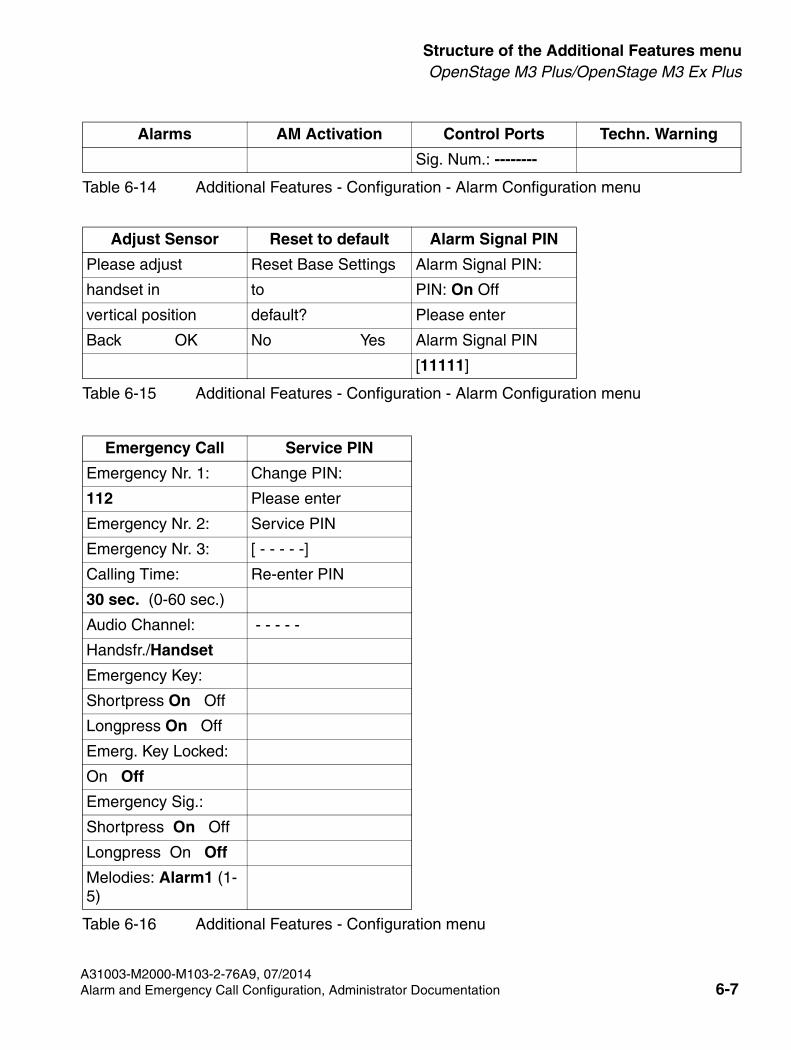
Sig. Num.: --------
Table 6-15 Additional Features - Configuration - Alarm Configuration menu
Adjust Sensor Reset to default Alarm Signal PIN
Please adjust Reset Base Settings Alarm Signal PIN:
handset in to PIN: On Off
vertical position default? Please enter
Back OK No Yes Alarm Signal PIN
[11111]
Emergency Call Service PIN
Emergency Nr. 1: Change PIN:
112 Please enter
Emergency Nr. 2: Service PIN
Emergency Nr. 3: [ - - - - -]
Calling Time: Re-enter PIN
30 sec. (0-60 sec.)
Audio Channel: - - - - -
Handsfr./Handset
Emergency Key:
Shortpress On Off
Longpress On Off
Emerg. Key Locked:
On Off
Emergency Sig.:
Shortpress On Off
Longpress On Off
Melodies: Alarm1 (1-5)
Table 6-16 Additional Features - Configuration menu
Alarms AM Activation Control Ports Techn. Warning
Table 6-14 Additional Features - Configuration - Alarm Configuration menu
A31003-M2000-M103-2-76A9, 07/2014Alarm and Emergency Call Configuration, Administrator Documentation 6-7
Structure of the Additional Features menu
SHB_PNG-Menu.fm
OpenStage M3 Plus/OpenStage M3 Ex Plus
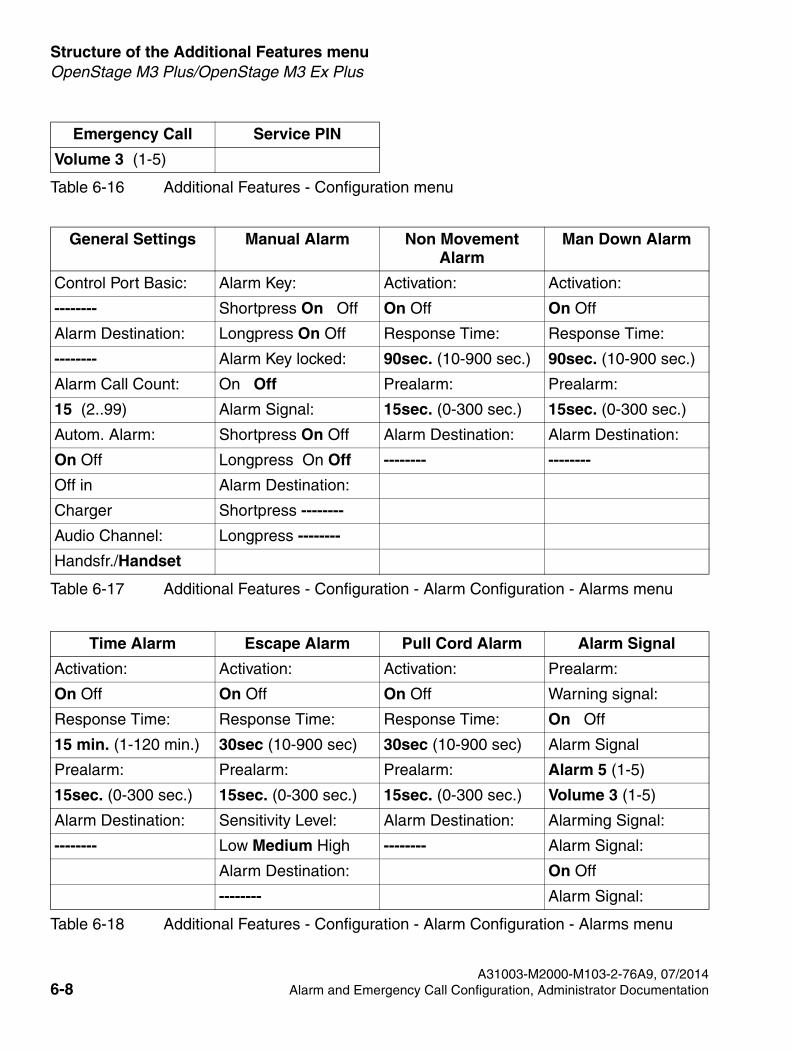
Volume 3 (1-5)
Table 6-17 Additional Features - Configuration - Alarm Configuration - Alarms menu
General Settings Manual Alarm Non Movement Alarm
Man Down Alarm
Control Port Basic: Alarm Key: Activation: Activation:
-------- Shortpress On Off On Off On Off
Alarm Destination: Longpress On Off Response Time: Response Time:
-------- Alarm Key locked: 90sec. (10-900 sec.) 90sec. (10-900 sec.)
Alarm Call Count: On Off Prealarm: Prealarm:
15 (2..99) Alarm Signal: 15sec. (0-300 sec.) 15sec. (0-300 sec.)
Autom. Alarm: Shortpress On Off Alarm Destination: Alarm Destination:
On Off Longpress On Off -------- --------
Off in Alarm Destination:
Charger Shortpress --------
Audio Channel: Longpress --------
Handsfr./Handset
Time Alarm Escape Alarm Pull Cord Alarm Alarm Signal
Activation: Activation: Activation: Prealarm:
On Off On Off On Off Warning signal:
Response Time: Response Time: Response Time: On Off
15 min. (1-120 min.) 30sec (10-900 sec) 30sec (10-900 sec) Alarm Signal
Prealarm: Prealarm: Prealarm: Alarm 5 (1-5)
15sec. (0-300 sec.) 15sec. (0-300 sec.) 15sec. (0-300 sec.) Volume 3 (1-5)
Alarm Destination: Sensitivity Level: Alarm Destination: Alarming Signal:
-------- Low Medium High -------- Alarm Signal:
Alarm Destination: On Off
-------- Alarm Signal:
Table 6-18 Additional Features - Configuration - Alarm Configuration - Alarms menu
Emergency Call Service PIN
Table 6-16 Additional Features - Configuration menu
A31003-M2000-M103-2-76A9, 07/20146-8 Alarm and Emergency Call Configuration, Administrator Documentation
SHB_PNG-Menu.fm
Structure of the Additional Features menuOpenStage M3 Plus/OpenStage M3 Ex Plus
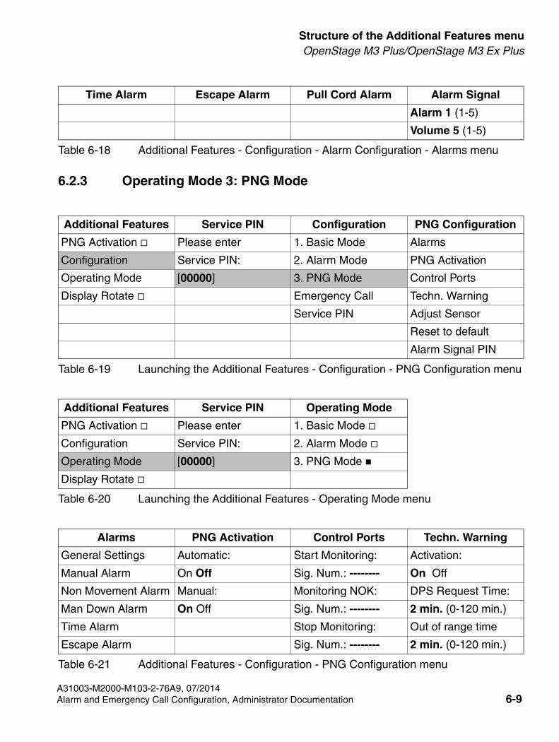
6.2.3 Operating Mode 3: PNG Mode
Table 6-19 Launching the Additional Features - Configuration - PNG Configuration menu
Additional Features Service PIN Configuration PNG Configuration
PNG Activation Please enter 1. Basic Mode Alarms
Configuration Service PIN: 2. Alarm Mode PNG Activation
Operating Mode [00000] 3. PNG Mode Control Ports
Display Rotate Emergency Call Techn. Warning
Service PIN Adjust Sensor
Reset to default
Alarm Signal PIN
Table 6-20 Launching the Additional Features - Operating Mode menu
Additional Features Service PIN Operating Mode
PNG Activation Please enter 1. Basic Mode
Configuration Service PIN: 2. Alarm Mode
Operating Mode [00000] 3. PNG Mode
Display Rotate
Alarm 1 (1-5)
Volume 5 (1-5)
Alarms PNG Activation Control Ports Techn. Warning
General Settings Automatic: Start Monitoring: Activation:
Manual Alarm On Off Sig. Num.: -------- On Off
Non Movement Alarm Manual: Monitoring NOK: DPS Request Time:
Man Down Alarm On Off Sig. Num.: -------- 2 min. (0-120 min.)
Time Alarm Stop Monitoring: Out of range time
Escape Alarm Sig. Num.: -------- 2 min. (0-120 min.)
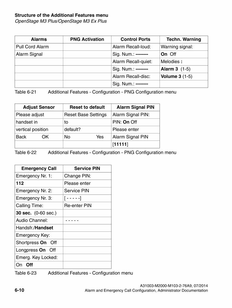
Table 6-21 Additional Features - Configuration - PNG Configuration menu
Time Alarm Escape Alarm Pull Cord Alarm Alarm Signal
Table 6-18 Additional Features - Configuration - Alarm Configuration - Alarms menu
A31003-M2000-M103-2-76A9, 07/2014Alarm and Emergency Call Configuration, Administrator Documentation 6-9
Structure of the Additional Features menu
SHB_PNG-Menu.fm
OpenStage M3 Plus/OpenStage M3 Ex Plus
Pull Cord Alarm Alarm Recall-loud: Warning signal:
Alarm Signal Sig. Num.: -------- On Off
Alarm Recall-quiet: Melodies :
Sig. Num.: -------- Alarm 3 (1-5)
Alarm Recall-disc: Volume 3 (1-5)
Sig. Num.: --------
Table 6-22 Additional Features - Configuration - PNG Configuration menu
Adjust Sensor Reset to default Alarm Signal PIN
Please adjust Reset Base Settings Alarm Signal PIN:
handset in to PIN: On Off
vertical position default? Please enter
Back OK No Yes Alarm Signal PIN
[11111]
Emergency Call Service PIN
Emergency Nr. 1: Change PIN:
112 Please enter
Emergency Nr. 2: Service PIN
Emergency Nr. 3: [ - - - - -]
Calling Time: Re-enter PIN
30 sec. (0-60 sec.)
Audio Channel: - - - - -
Handsfr./Handset
Emergency Key:
Shortpress On Off
Longpress On Off
Emerg. Key Locked:
On Off
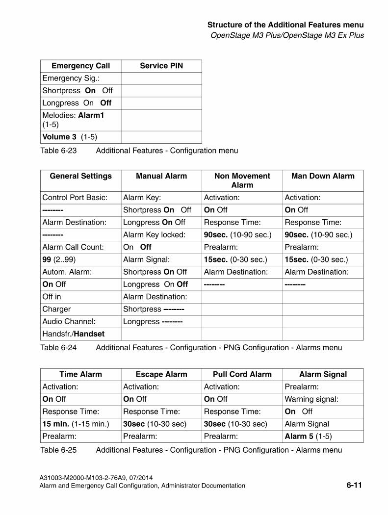
Table 6-23 Additional Features - Configuration menu
Alarms PNG Activation Control Ports Techn. Warning
Table 6-21 Additional Features - Configuration - PNG Configuration menu
A31003-M2000-M103-2-76A9, 07/20146-10 Alarm and Emergency Call Configuration, Administrator Documentation
SHB_PNG-Menu.fm
Structure of the Additional Features menuOpenStage M3 Plus/OpenStage M3 Ex Plus
Emergency Sig.:
Shortpress On Off
Longpress On Off
Melodies: Alarm1 (1-5)
Volume 3 (1-5)
Table 6-24 Additional Features - Configuration - PNG Configuration - Alarms menu
General Settings Manual Alarm Non Movement Alarm
Man Down Alarm
Control Port Basic: Alarm Key: Activation: Activation:
-------- Shortpress On Off On Off On Off
Alarm Destination: Longpress On Off Response Time: Response Time:
-------- Alarm Key locked: 90sec. (10-90 sec.) 90sec. (10-90 sec.)
Alarm Call Count: On Off Prealarm: Prealarm:
99 (2..99) Alarm Signal: 15sec. (0-30 sec.) 15sec. (0-30 sec.)
Autom. Alarm: Shortpress On Off Alarm Destination: Alarm Destination:
On Off Longpress On Off -------- --------
Off in Alarm Destination:
Charger Shortpress --------
Audio Channel: Longpress --------
Handsfr./Handset
Time Alarm Escape Alarm Pull Cord Alarm Alarm Signal
Activation: Activation: Activation: Prealarm:
On Off On Off On Off Warning signal:
Response Time: Response Time: Response Time: On Off
15 min. (1-15 min.) 30sec (10-30 sec) 30sec (10-30 sec) Alarm Signal
Prealarm: Prealarm: Prealarm: Alarm 5 (1-5)
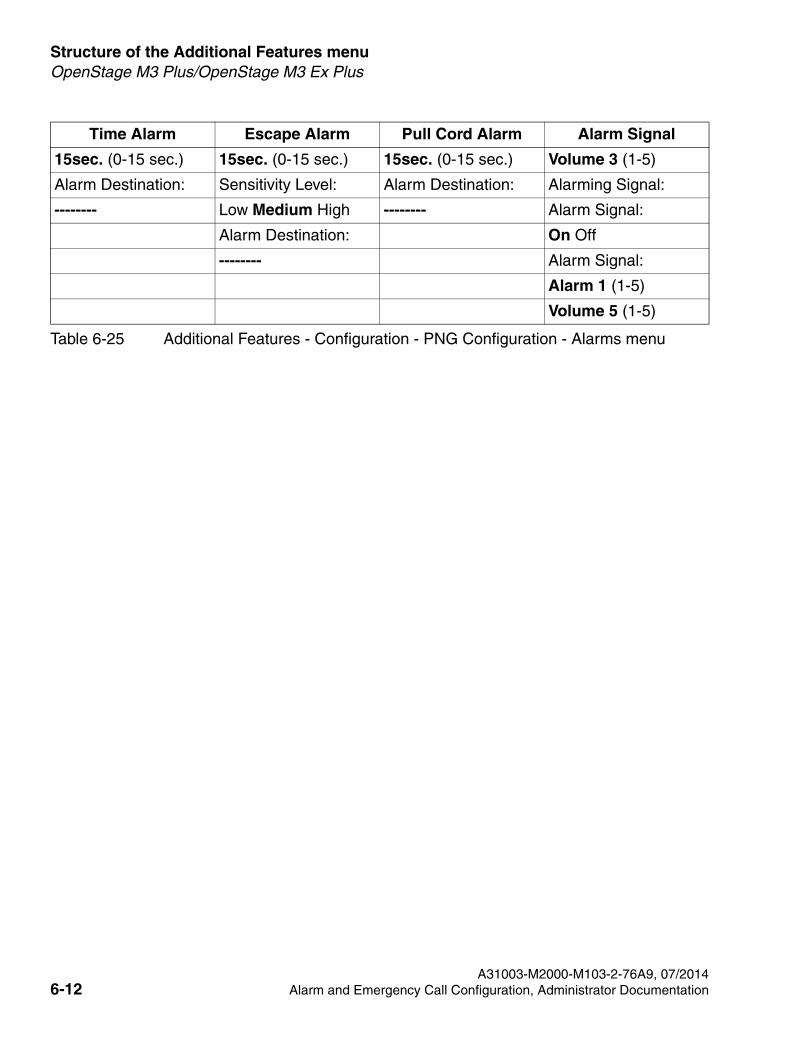
Table 6-25 Additional Features - Configuration - PNG Configuration - Alarms menu
Emergency Call Service PIN
Table 6-23 Additional Features - Configuration menu
A31003-M2000-M103-2-76A9, 07/2014Alarm and Emergency Call Configuration, Administrator Documentation 6-11
Structure of the Additional Features menu
SHB_PNG-Menu.fm
OpenStage M3 Plus/OpenStage M3 Ex Plus
15sec. (0-15 sec.) 15sec. (0-15 sec.) 15sec. (0-15 sec.) Volume 3 (1-5)
Alarm Destination: Sensitivity Level: Alarm Destination: Alarming Signal:
-------- Low Medium High -------- Alarm Signal:
Alarm Destination: On Off
-------- Alarm Signal:
Alarm 1 (1-5)
Volume 5 (1-5)
Time Alarm Escape Alarm Pull Cord Alarm Alarm Signal
Table 6-25 Additional Features - Configuration - PNG Configuration - Alarms menu
A31003-M2000-M103-2-76A9, 07/20146-12 Alarm and Emergency Call Configuration, Administrator Documentation
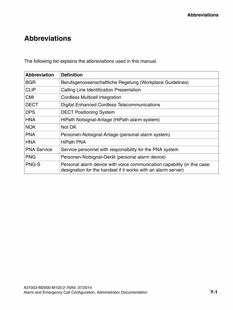
SHB_PNG_abb.fm
A31003-M2000-M103-2-76A9, 07/2014Alarm and Emergency Call Configuration, Administrator Documentation Y-1
For internal use only Abbreviations
Abbreviations Y
Abbreviation Definition
BGR Berufsgenossenschaftliche Regelung (Workplace Guidelines)
CLIP Calling Line Identification Presentation
CMI Cordless Multicell Integration
DECT Digital Enhanced Cordless Telecommunications
DPS DECT Positioning System
HNA HiPath Notsignal-Anlage (HiPath alarm system)
NOK Not OK
PNA Personen-Notsignal-Anlage (personal alarm system)
HNA HiPath PNA
PNA Service Service personnel with responsibility for the PNA system
PNG Personen-Notsignal-Gerät (personal alarm device)
PNG-S Personal alarm device with voice communication capability (in this case: designation for the handset if it works with an alarm server)
The following list explains the abbreviations used in this manual.
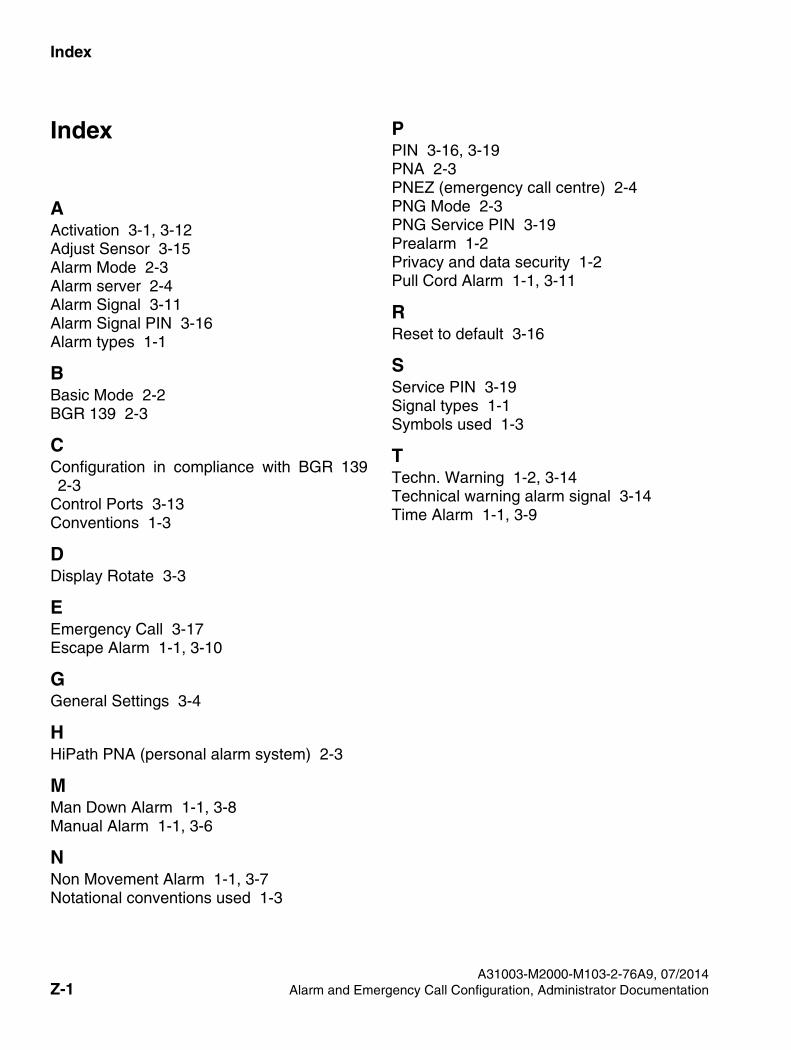
Index For internal use only
A31003-M2000-M103-2-76A9, 07/2014Z-1 Alarm and Emergency Call Configuration, Administrator Documentation
SHB_PNG_IX.fm
Index Z
AActivation 3-1, 3-12Adjust Sensor 3-15Alarm Mode 2-3Alarm server 2-4Alarm Signal 3-11Alarm Signal PIN 3-16Alarm types 1-1
BBasic Mode 2-2BGR 139 2-3
CConfiguration in compliance with BGR 139 2-3
Control Ports 3-13Conventions 1-3
DDisplay Rotate 3-3
EEmergency Call 3-17Escape Alarm 1-1, 3-10
GGeneral Settings 3-4
HHiPath PNA (personal alarm system) 2-3
MMan Down Alarm 1-1, 3-8Manual Alarm 1-1, 3-6
NNon Movement Alarm 1-1, 3-7Notational conventions used 1-3
PPIN 3-16, 3-19PNA 2-3PNEZ (emergency call centre) 2-4PNG Mode 2-3PNG Service PIN 3-19Prealarm 1-2Privacy and data security 1-2Pull Cord Alarm 1-1, 3-11
RReset to default 3-16
SService PIN 3-19Signal types 1-1Symbols used 1-3
TTechn. Warning 1-2, 3-14Technical warning alarm signal 3-14Time Alarm 1-1, 3-9