Embed Size (px)
Citation preview
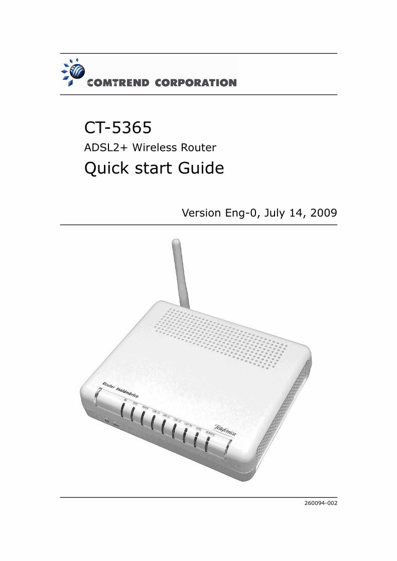
CT-5365 ADSL2+ Wireless Router
Quick start Guide
Version Eng-0, July 14, 2009
260094-002

1
Preface
This manual provides information related to quick start guide of this device. The
individual reading this manual is presumed to have a basic understanding of
telecommunications terminology and concepts.
If you find the product to be inoperable or malfunctioning, please contact technical
support for immediate service by email at [email protected]
For product update, new product release, manual revision, or software upgrades,
please visit our website at http://www.comtrend.com
Important Safety Instructions
With reference to unpacking, installation, use, and maintenance of your electronic
device, the following basic guidelines are recommended:
Do not use or install this product near water, to avoid fire or shock hazard. For
example, near a bathtub, kitchen sink or laundry tub, or near a swimming pool.
Also, do not expose the equipment to rain or damp areas (e.g. a wet basement).
Do not connect the power supply cord on elevated surfaces. Allow it to lie freely.
There should be no obstructions in its path and no heavy items should be placed
on the cord. In addition, do not walk on, step on, or mistreat the cord.
Use only the power cord and adapter that are shipped with this device.
To safeguard the equipment against overheating, make sure that all openings in
the unit that offer exposure to air are not blocked.
Avoid using a telephone (other than a cordless type) during an electrical storm.
There may be a remote risk of electric shock from lightening. Also, do not use
the telephone to report a gas leak in the vicinity of the leak.
Never install telephone wiring during stormy weather conditions.
CAUTION:
To reduce the risk of fire, use only No. 26 AWG or larger telecommunication line
cord.
Always disconnect all telephone lines from the wall outlet before servicing or
disassembling this equipment.
WARNING
Disconnect the power line from the device before servicing.
Power supply specifications are clearly stated in Appendix C of User Guide.
Copyright
Copyright©2009 Comtrend Corporation. All rights reserved. The information
contained herein is proprietary to Comtrend Corporation. No part of this document
may be translated, transcribed, reproduced, in any form, or by any means without
prior written consent of Comtrend Corporation.
NOTE: This document is subject to change without notice.

2
Protect Our Environment
This symbol indicates that when the equipment has reached the end of its
useful life, it must be taken to a recycling centre and processed separate
from domestic waste.
The cardboard box, the plastic contained in the packaging, and the parts that make
up this router can be recycled in accordance with regionally established regulations.
Never dispose of this electronic equipment along with your household waste. You
may be subject to penalties or sanctions under the law. Instead, ask for disposal
instructions from your municipal government.

3
Table of Contents CHAPTER 1 SUMMARY ..................................................................................................................... 4
CHAPTER 2 CHANGE PASSWORD .................................................................................................. 5 2.1 PASSWORDS ..................................................................................................................................... 5 2.2 DEFAULT SETTINGS ......................................................................................................................... 5
CHAPTER 3 ROUTER’S CONFIGURATION ................................................................................... 6 3.1 DYNAMIC MULTI-CONFIGURATION ................................................................................................... 6
3.1.1 Setup WAN port using manual setup ................................................................................. 6 3.1.2 Setup LAN port ................................................................................................................. 9 3.1.3 Setup Access control ....................................................................................................... 11
3.2 STATIC MULTI-CONFIGURATION ...................................................................................................... 12 3.2.1 Setup WAN port using Quick Setup ................................................................................. 12 3.2.2 Setup Access control ....................................................................................................... 17
3.3 SINGLE DYNAMIC CONFIGURATION (BRIDGING) ............................................................................. 19 3.3.1 Setup WAN port ............................................................................................................... 19 3.3.2 Setup LAN port ............................................................................................................... 21 3.3.3 Setup Access control ....................................................................................................... 22
3.4 SINGLE STATIC CONFIGURATION (IPOA) ........................................................................................ 24 3.4.1 Setup WAN port ............................................................................................................... 24 3.4.2 Setup LAN port ............................................................................................................... 27 3.4.3 Setup Access control ....................................................................................................... 28
3.5 NAT .............................................................................................................................................. 30 3.5.1 Virtual Servers ................................................................................................................ 30
3.6 WIRELESS ...................................................................................................................................... 32 3.6.1 Basic ............................................................................................................................... 32 3.6.2 Security ........................................................................................................................... 33 3.6.3 MAC Filter ...................................................................................................................... 39 3.6.4 Advanced ........................................................................................................................ 40 3.6.5 Station Info...................................................................................................................... 43
3.7 UPDATE SOFTWARE ....................................................................................................................... 43 3.8 SAVE AND REBOOT ........................................................................................................................ 44
4
Chapter 1 Summary
Comtrend’s CT-5365 is an 802.11g (54Mbps) Wireless and Wired ADSL2+ Router. It
comes equipped with four 10/100 Base-T Ethernet ports and an ADSL2+ port for
wired connectivity. An integrated 802.11g WLAN Access Point (AP) with Wi-Fi
Protected Setup (WPS) provides wireless coverage.
To setup the ADSL service that provides Telefónica, it is recommended to follow the
instructions in the User Manual that came with the kit.
This guide complements the manual explaining how to use router’s web configurator
rather than using the setup Wizard included in the kit for the Microsoft Windows SO.
We recommended using the Telefonica’s Wizard.
The CT-5365 contains state of the art security features, such as WPA data
encryption, Firewall and VPN pass through. This model supports up to 16
contiguous virtual connections allowing for multiple simultaneous Internet
connections. The front and back panels are TR-068 compliant, which means they
are color-coded for easy installation and use. These features make the CT-5365
especially suited to a home or small business environment.
NOTE: Before to use Manufacturer’s tool of this product and Telefonica’s tools, you
are informed that this procedure is a orientate procedure. Telefonica does not have
support regarding this document.
5
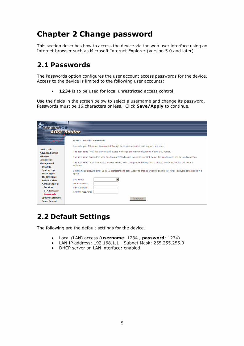
Chapter 2 Change password
This section describes how to access the device via the web user interface using an
Internet browser such as Microsoft Internet Explorer (version 5.0 and later).
2.1 Passwords
The Passwords option configures the user account access passwords for the device.
Access to the device is limited to the following user accounts:
1234 is to be used for local unrestricted access control.
Use the fields in the screen below to select a username and change its password.
Passwords must be 16 characters or less. Click Save/Apply to continue.
2.2 Default Settings
The following are the default settings for the device.
Local (LAN) access (username: 1234 , password: 1234)
LAN IP address: 192.168.1.1 - Subnet Mask: 255.255.255.0
DHCP server on LAN interface: enabled
6
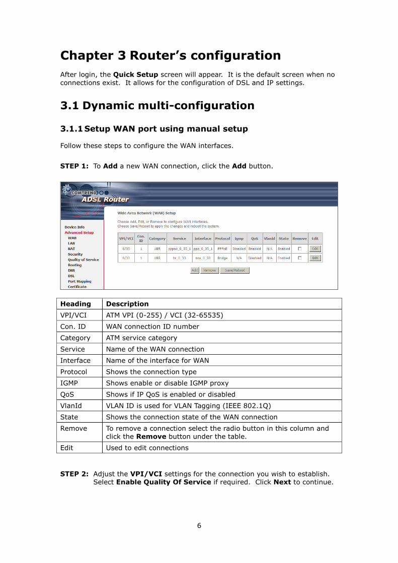
Chapter 3 Router’s configuration
After login, the Quick Setup screen will appear. It is the default screen when no
connections exist. It allows for the configuration of DSL and IP settings.
3.1 Dynamic multi-configuration
3.1.1 Setup WAN port using manual setup
Follow these steps to configure the WAN interfaces.
STEP 1: To Add a new WAN connection, click the Add button.
Heading Description
VPI/VCI ATM VPI (0-255) / VCI (32-65535)
Con. ID WAN connection ID number
Category ATM service category
Service Name of the WAN connection
Interface Name of the interface for WAN
Protocol Shows the connection type
IGMP Shows enable or disable IGMP proxy
QoS Shows if IP QoS is enabled or disabled
VlanId VLAN ID is used for VLAN Tagging (IEEE 802.1Q)
State Shows the connection state of the WAN connection
Remove To remove a connection select the radio button in this column and
click the Remove button under the table.
Edit Used to edit connections
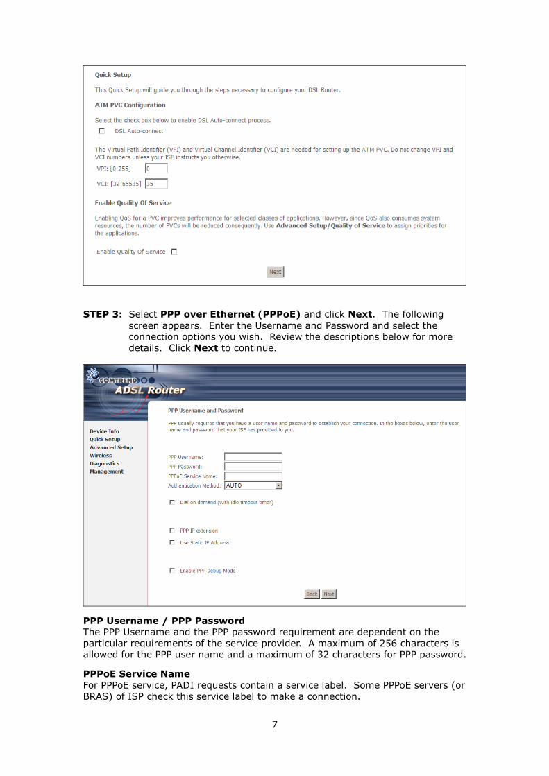
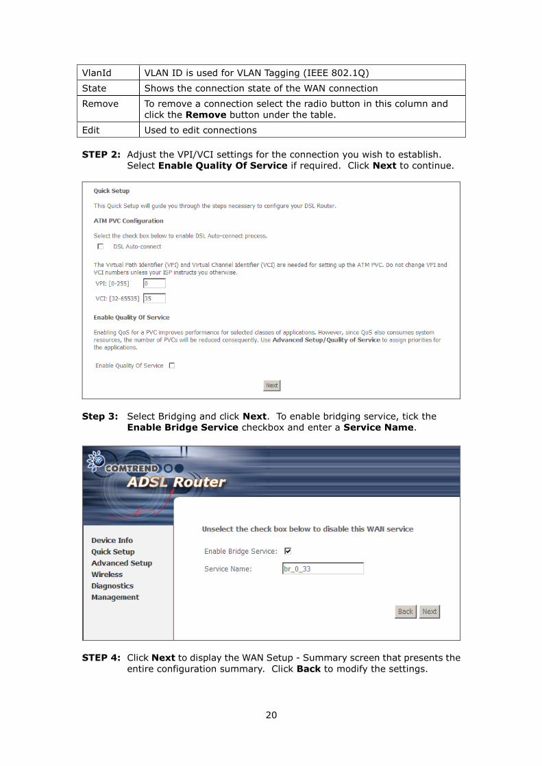
STEP 2: Adjust the VPI/VCI settings for the connection you wish to establish.
Select Enable Quality Of Service if required. Click Next to continue.
7
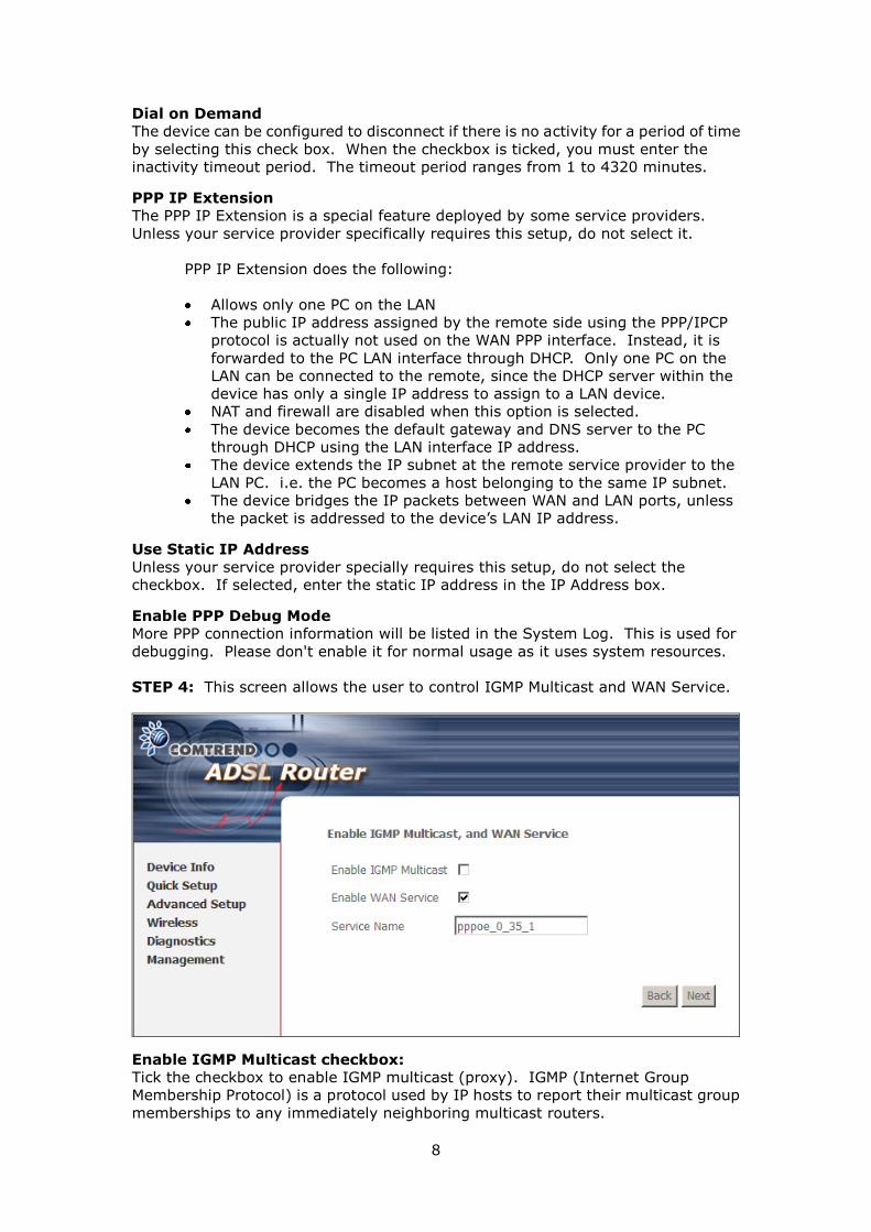
STEP 3: Select PPP over Ethernet (PPPoE) and click Next. The following
screen appears. Enter the Username and Password and select the
connection options you wish. Review the descriptions below for more
details. Click Next to continue.
PPP Username / PPP Password
The PPP Username and the PPP password requirement are dependent on the
particular requirements of the service provider. A maximum of 256 characters is
allowed for the PPP user name and a maximum of 32 characters for PPP password.
PPPoE Service Name
For PPPoE service, PADI requests contain a service label. Some PPPoE servers (or
BRAS) of ISP check this service label to make a connection.
8
Dial on Demand
The device can be configured to disconnect if there is no activity for a period of time
by selecting this check box. When the checkbox is ticked, you must enter the
inactivity timeout period. The timeout period ranges from 1 to 4320 minutes.
PPP IP Extension
The PPP IP Extension is a special feature deployed by some service providers.
Unless your service provider specifically requires this setup, do not select it.
PPP IP Extension does the following:
Allows only one PC on the LAN
The public IP address assigned by the remote side using the PPP/IPCP
protocol is actually not used on the WAN PPP interface. Instead, it is
forwarded to the PC LAN interface through DHCP. Only one PC on the
LAN can be connected to the remote, since the DHCP server within the
device has only a single IP address to assign to a LAN device.
NAT and firewall are disabled when this option is selected.
The device becomes the default gateway and DNS server to the PC
through DHCP using the LAN interface IP address.
The device extends the IP subnet at the remote service provider to the
LAN PC. i.e. the PC becomes a host belonging to the same IP subnet.
The device bridges the IP packets between WAN and LAN ports, unless
the packet is addressed to the device’s LAN IP address.
Use Static IP Address
Unless your service provider specially requires this setup, do not select the
checkbox. If selected, enter the static IP address in the IP Address box.
Enable PPP Debug Mode
More PPP connection information will be listed in the System Log. This is used for
debugging. Please don't enable it for normal usage as it uses system resources.
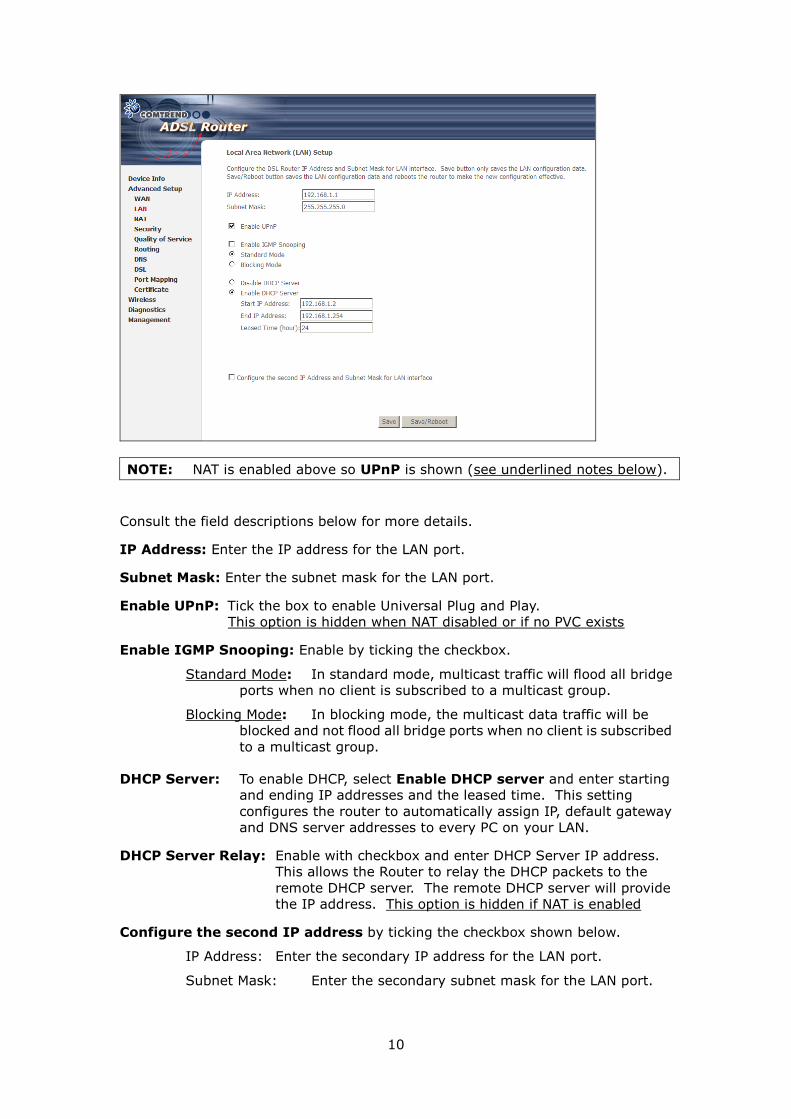
STEP 4: This screen allows the user to control IGMP Multicast and WAN Service.
Enable IGMP Multicast checkbox:
Tick the checkbox to enable IGMP multicast (proxy). IGMP (Internet Group
Membership Protocol) is a protocol used by IP hosts to report their multicast group
memberships to any immediately neighboring multicast routers.

9
Enable WAN Service checkbox:
Tick this item to enable the ATM service. Untick it to stop the ATM service.
Service Name: This is the WAN Service label.
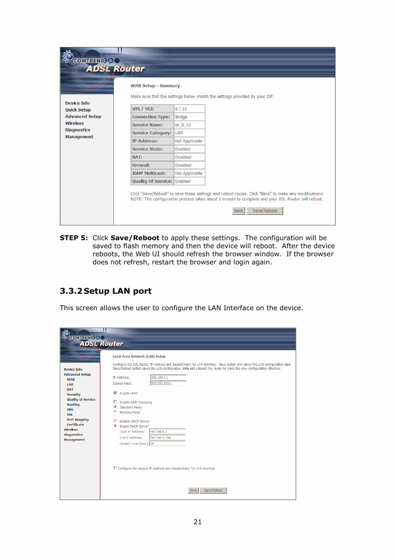
STEP 5: Click Next to display the WAN Setup - Summary screen that presents the
entire configuration summary. Click Back to modify the settings.
STEP 6: Click Save/Reboot to apply these settings. The configuration will be
saved to flash memory and then the device will reboot. After the device
reboots, the Web UI should refresh the browser window. If the browser
does not refresh, restart the browser and login again.
3.1.2 Setup LAN port
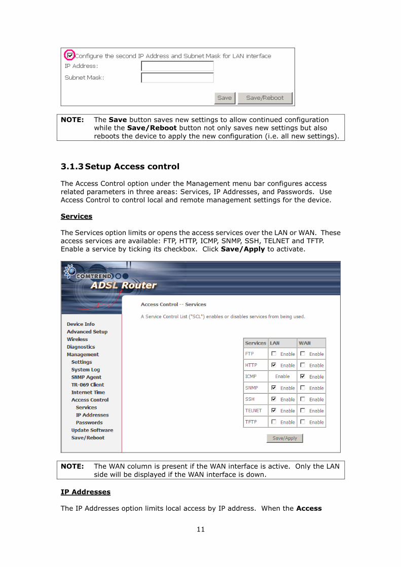
This screen allows the user to configure the LAN Interface on the device.
10
NOTE: NAT is enabled above so UPnP is shown (see underlined notes below).
Consult the field descriptions below for more details.
IP Address: Enter the IP address for the LAN port.
Subnet Mask: Enter the subnet mask for the LAN port.
Enable UPnP: Tick the box to enable Universal Plug and Play.
This option is hidden when NAT disabled or if no PVC exists
Enable IGMP Snooping: Enable by ticking the checkbox.
Standard Mode: In standard mode, multicast traffic will flood all bridge
ports when no client is subscribed to a multicast group.
Blocking Mode: In blocking mode, the multicast data traffic will be
blocked and not flood all bridge ports when no client is subscribed
to a multicast group.
DHCP Server: To enable DHCP, select Enable DHCP server and enter starting
and ending IP addresses and the leased time. This setting
configures the router to automatically assign IP, default gateway
and DNS server addresses to every PC on your LAN.
DHCP Server Relay: Enable with checkbox and enter DHCP Server IP address.
This allows the Router to relay the DHCP packets to the
remote DHCP server. The remote DHCP server will provide
the IP address. This option is hidden if NAT is enabled
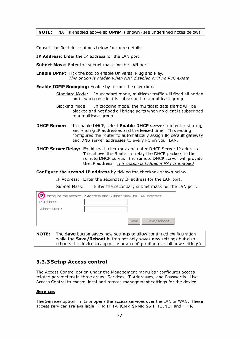
Configure the second IP address by ticking the checkbox shown below.
IP Address: Enter the secondary IP address for the LAN port.
Subnet Mask: Enter the secondary subnet mask for the LAN port.
11
NOTE: The Save button saves new settings to allow continued configuration
while the Save/Reboot button not only saves new settings but also
reboots the device to apply the new configuration (i.e. all new settings).
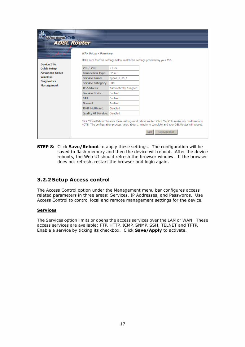
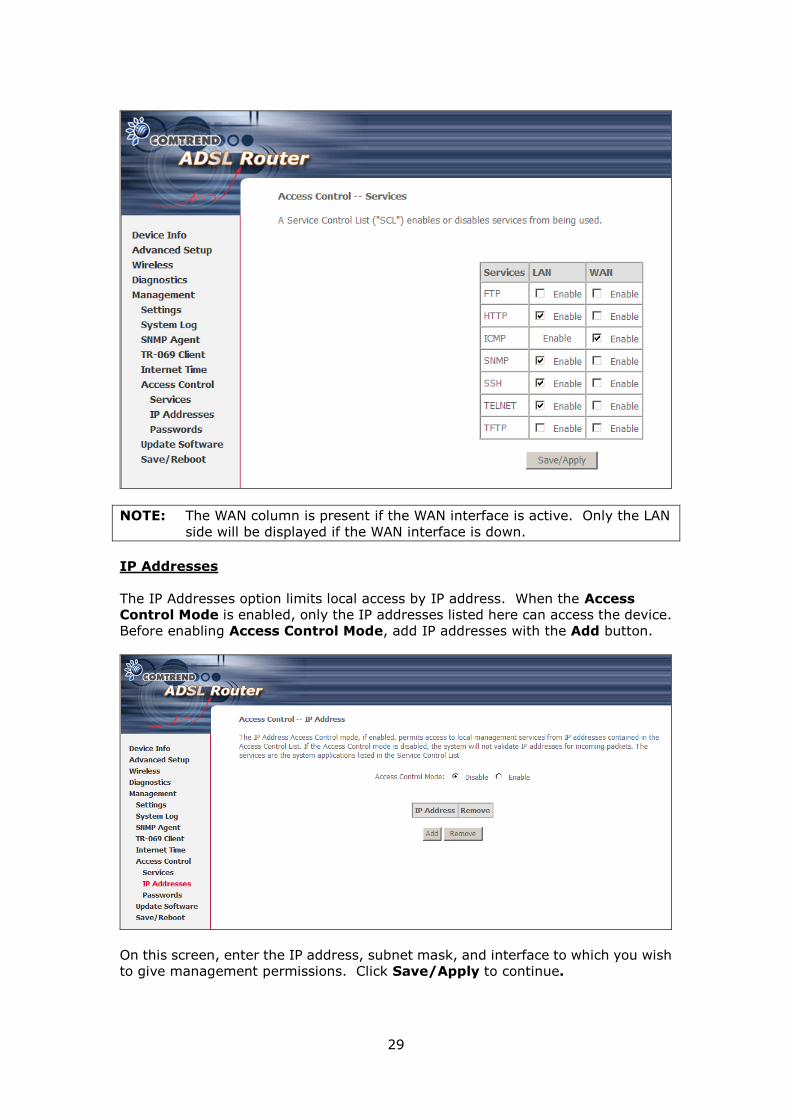
3.1.3 Setup Access control
The Access Control option under the Management menu bar configures access
related parameters in three areas: Services, IP Addresses, and Passwords. Use
Access Control to control local and remote management settings for the device.
Services
The Services option limits or opens the access services over the LAN or WAN. These
access services are available: FTP, HTTP, ICMP, SNMP, SSH, TELNET and TFTP.
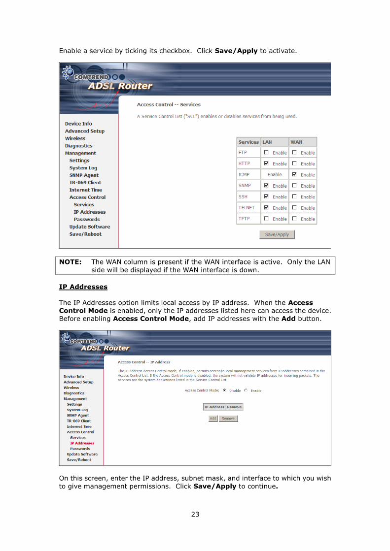
Enable a service by ticking its checkbox. Click Save/Apply to activate.
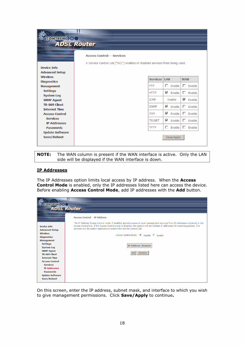
NOTE: The WAN column is present if the WAN interface is active. Only the LAN
side will be displayed if the WAN interface is down.
IP Addresses
The IP Addresses option limits local access by IP address. When the Access
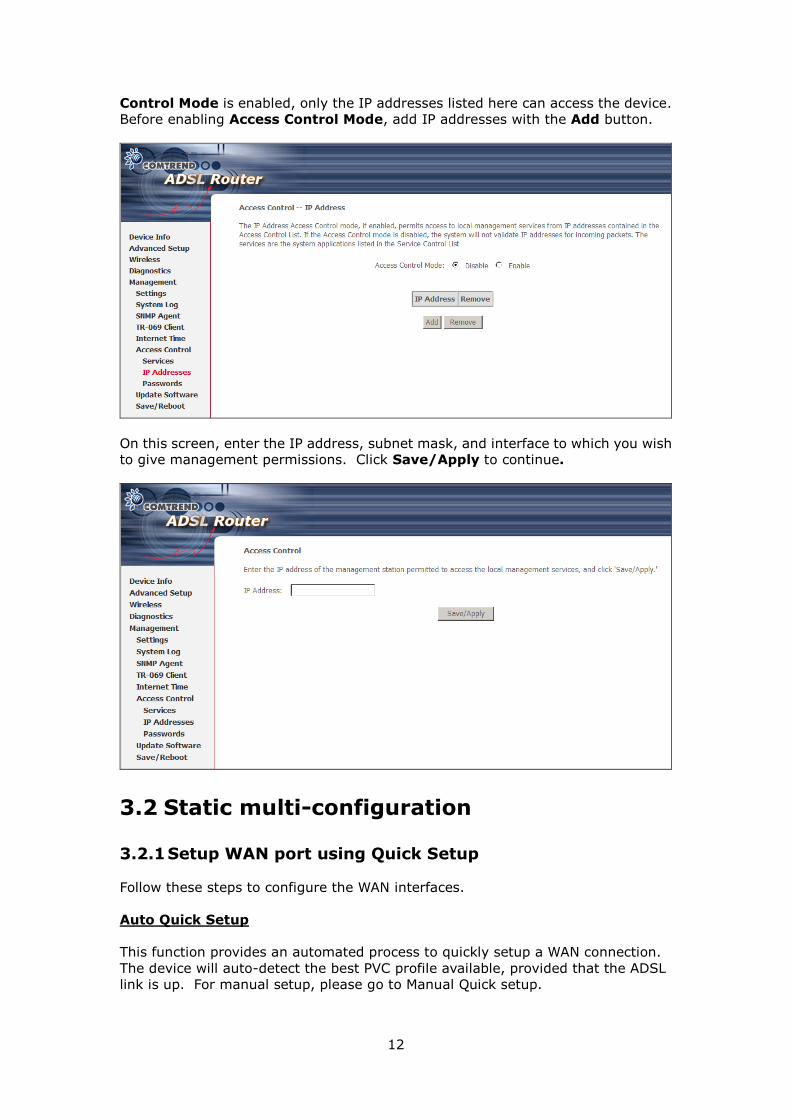
12
Control Mode is enabled, only the IP addresses listed here can access the device.
Before enabling Access Control Mode, add IP addresses with the Add button.
On this screen, enter the IP address, subnet mask, and interface to which you wish
to give management permissions. Click Save/Apply to continue.
3.2 Static multi-configuration
3.2.1 Setup WAN port using Quick Setup
Follow these steps to configure the WAN interfaces.
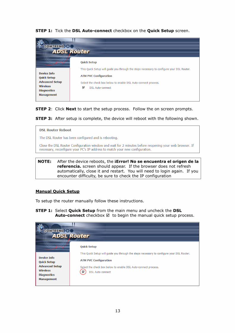
Auto Quick Setup
This function provides an automated process to quickly setup a WAN connection.
The device will auto-detect the best PVC profile available, provided that the ADSL
link is up. For manual setup, please go to Manual Quick setup.
13
STEP 1: Tick the DSL Auto-connect checkbox on the Quick Setup screen.
STEP 2: Click Next to start the setup process. Follow the on screen prompts.
STEP 3: After setup is complete, the device will reboot with the following shown.
NOTE: After the device reboots, the ¡Error! No se encuentra el origen de la
referencia. screen should appear. If the browser does not refresh
automatically, close it and restart. You will need to login again. If you
encounter difficulty, be sure to check the IP configuration
Manual Quick Setup
To setup the router manually follow these instructions.
STEP 1: Select Quick Setup from the main menu and uncheck the DSL Auto-connect checkbox to begin the manual quick setup process.
14
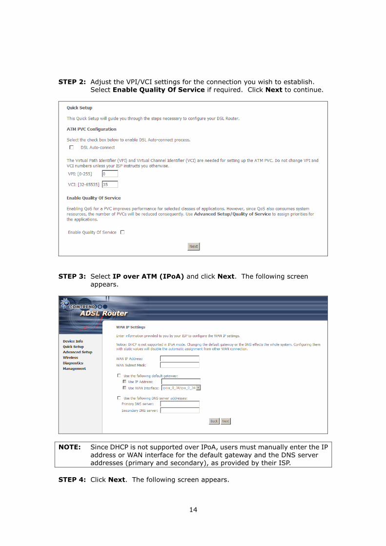
STEP 2: Adjust the VPI/VCI settings for the connection you wish to establish.
Select Enable Quality Of Service if required. Click Next to continue.
STEP 3: Select IP over ATM (IPoA) and click Next. The following screen
appears.
NOTE: Since DHCP is not supported over IPoA, users must manually enter the IP
address or WAN interface for the default gateway and the DNS server
addresses (primary and secondary), as provided by their ISP.
STEP 4: Click Next. The following screen appears.
15
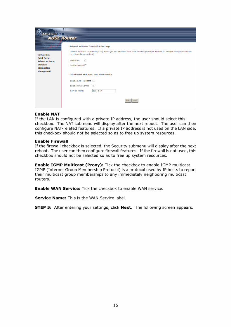
Enable NAT
If the LAN is configured with a private IP address, the user should select this
checkbox. The NAT submenu will display after the next reboot. The user can then
configure NAT-related features. If a private IP address is not used on the LAN side,
this checkbox should not be selected so as to free up system resources.
Enable Firewall
If the firewall checkbox is selected, the Security submenu will display after the next
reboot. The user can then configure firewall features. If the firewall is not used, this
checkbox should not be selected so as to free up system resources.
Enable IGMP Multicast (Proxy): Tick the checkbox to enable IGMP multicast.
IGMP (Internet Group Membership Protocol) is a protocol used by IP hosts to report
their multicast group memberships to any immediately neighboring multicast
routers.
Enable WAN Service: Tick the checkbox to enable WAN service.
Service Name: This is the WAN Service label.
STEP 5: After entering your settings, click Next. The following screen appears.
16
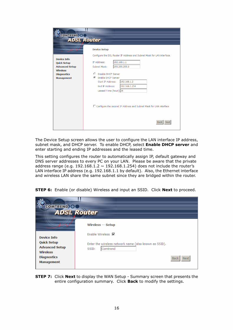
The Device Setup screen allows the user to configure the LAN interface IP address,
subnet mask, and DHCP server. To enable DHCP, select Enable DHCP server and
enter starting and ending IP addresses and the leased time.
This setting configures the router to automatically assign IP, default gateway and
DNS server addresses to every PC on your LAN. Please be aware that the private
address range (e.g. 192.168.1.2 ~ 192.168.1.254) does not include the router’s
LAN interface IP address (e.g. 192.168.1.1 by default). Also, the Ethernet interface
and wireless LAN share the same subnet since they are bridged within the router.
STEP 6: Enable (or disable) Wireless and input an SSID. Click Next to proceed.
STEP 7: Click Next to display the WAN Setup - Summary screen that presents the
entire configuration summary. Click Back to modify the settings.
17
STEP 8: Click Save/Reboot to apply these settings. The configuration will be
saved to flash memory and then the device will reboot. After the device
reboots, the Web UI should refresh the browser window. If the browser
does not refresh, restart the browser and login again.
3.2.2 Setup Access control
The Access Control option under the Management menu bar configures access
related parameters in three areas: Services, IP Addresses, and Passwords. Use
Access Control to control local and remote management settings for the device.
Services
The Services option limits or opens the access services over the LAN or WAN. These
access services are available: FTP, HTTP, ICMP, SNMP, SSH, TELNET and TFTP.
Enable a service by ticking its checkbox. Click Save/Apply to activate.
18
NOTE: The WAN column is present if the WAN interface is active. Only the LAN
side will be displayed if the WAN interface is down.
IP Addresses
The IP Addresses option limits local access by IP address. When the Access
Control Mode is enabled, only the IP addresses listed here can access the device.
Before enabling Access Control Mode, add IP addresses with the Add button.
On this screen, enter the IP address, subnet mask, and interface to which you wish
to give management permissions. Click Save/Apply to continue.
19
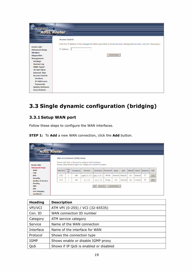
3.3 Single dynamic configuration (bridging)
3.3.1 Setup WAN port
Follow these steps to configure the WAN interfaces.
STEP 1: To Add a new WAN connection, click the Add button.
Heading Description
VPI/VCI ATM VPI (0-255) / VCI (32-65535)
Con. ID WAN connection ID number
Category ATM service category
Service Name of the WAN connection
Interface Name of the interface for WAN
Protocol Shows the connection type
IGMP Shows enable or disable IGMP proxy
QoS Shows if IP QoS is enabled or disabled
20
VlanId VLAN ID is used for VLAN Tagging (IEEE 802.1Q)
State Shows the connection state of the WAN connection
Remove To remove a connection select the radio button in this column and
click the Remove button under the table.
Edit Used to edit connections
STEP 2: Adjust the VPI/VCI settings for the connection you wish to establish.
Select Enable Quality Of Service if required. Click Next to continue.
Step 3: Select Bridging and click Next. To enable bridging service, tick the
Enable Bridge Service checkbox and enter a Service Name.
STEP 4: Click Next to display the WAN Setup - Summary screen that presents the
entire configuration summary. Click Back to modify the settings.
21
STEP 5: Click Save/Reboot to apply these settings. The configuration will be
saved to flash memory and then the device will reboot. After the device
reboots, the Web UI should refresh the browser window. If the browser
does not refresh, restart the browser and login again.
3.3.2 Setup LAN port
This screen allows the user to configure the LAN Interface on the device.
22
NOTE: NAT is enabled above so UPnP is shown (see underlined notes below).
Consult the field descriptions below for more details.
IP Address: Enter the IP address for the LAN port.
Subnet Mask: Enter the subnet mask for the LAN port.
Enable UPnP: Tick the box to enable Universal Plug and Play.
This option is hidden when NAT disabled or if no PVC exists
Enable IGMP Snooping: Enable by ticking the checkbox.
Standard Mode: In standard mode, multicast traffic will flood all bridge
ports when no client is subscribed to a multicast group.
Blocking Mode: In blocking mode, the multicast data traffic will be
blocked and not flood all bridge ports when no client is subscribed
to a multicast group.
DHCP Server: To enable DHCP, select Enable DHCP server and enter starting
and ending IP addresses and the leased time. This setting
configures the router to automatically assign IP, default gateway
and DNS server addresses to every PC on your LAN.
DHCP Server Relay: Enable with checkbox and enter DHCP Server IP address.
This allows the Router to relay the DHCP packets to the
remote DHCP server. The remote DHCP server will provide
the IP address. This option is hidden if NAT is enabled
Configure the second IP address by ticking the checkbox shown below.
IP Address: Enter the secondary IP address for the LAN port.
Subnet Mask: Enter the secondary subnet mask for the LAN port.
NOTE: The Save button saves new settings to allow continued configuration
while the Save/Reboot button not only saves new settings but also
reboots the device to apply the new configuration (i.e. all new settings).
3.3.3 Setup Access control
The Access Control option under the Management menu bar configures access
related parameters in three areas: Services, IP Addresses, and Passwords. Use
Access Control to control local and remote management settings for the device.
Services
The Services option limits or opens the access services over the LAN or WAN. These
access services are available: FTP, HTTP, ICMP, SNMP, SSH, TELNET and TFTP.
23
Enable a service by ticking its checkbox. Click Save/Apply to activate.
NOTE: The WAN column is present if the WAN interface is active. Only the LAN
side will be displayed if the WAN interface is down.
IP Addresses
The IP Addresses option limits local access by IP address. When the Access
Control Mode is enabled, only the IP addresses listed here can access the device.
Before enabling Access Control Mode, add IP addresses with the Add button.
On this screen, enter the IP address, subnet mask, and interface to which you wish
to give management permissions. Click Save/Apply to continue.
24
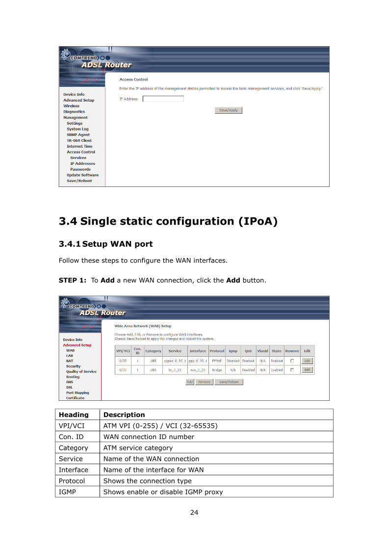
3.4 Single static configuration (IPoA)
3.4.1 Setup WAN port
Follow these steps to configure the WAN interfaces.
STEP 1: To Add a new WAN connection, click the Add button.
Heading Description
VPI/VCI ATM VPI (0-255) / VCI (32-65535)
Con. ID WAN connection ID number
Category ATM service category
Service Name of the WAN connection
Interface Name of the interface for WAN
Protocol Shows the connection type
IGMP Shows enable or disable IGMP proxy
25
QoS Shows if IP QoS is enabled or disabled
VlanId VLAN ID is used for VLAN Tagging (IEEE 802.1Q)
State Shows the connection state of the WAN connection
Remove To remove a connection select the radio button in this column and
click the Remove button under the table.
Edit Used to edit connections
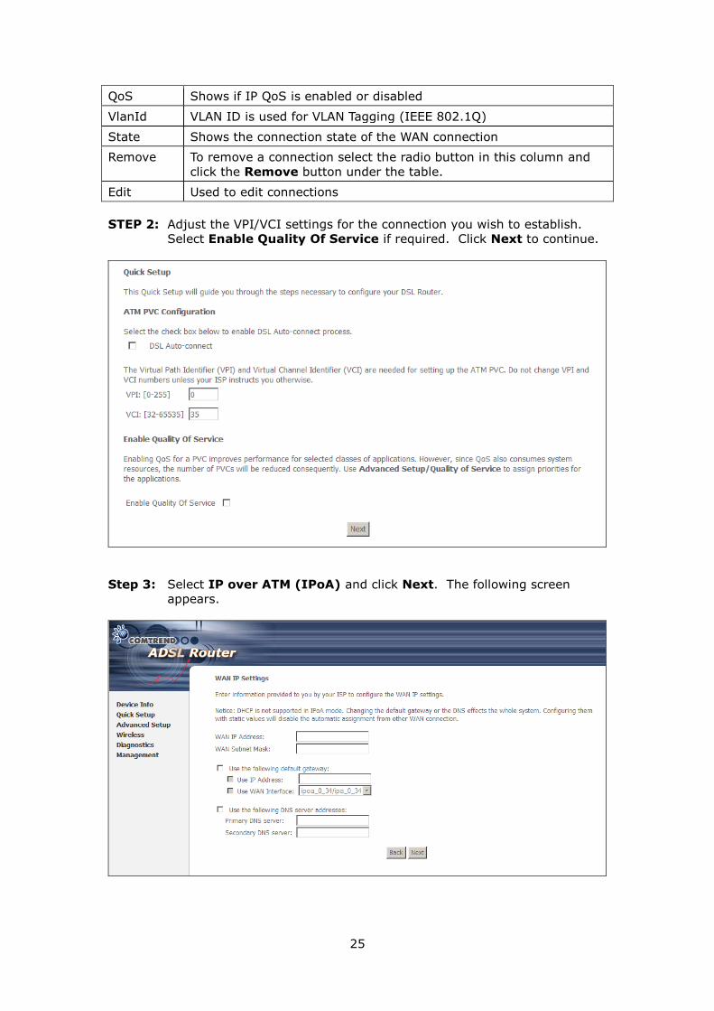
STEP 2: Adjust the VPI/VCI settings for the connection you wish to establish.
Select Enable Quality Of Service if required. Click Next to continue.
Step 3: Select IP over ATM (IPoA) and click Next. The following screen
appears.
26
NOTE: Since DHCP is not supported over IPoA, users must manually enter the IP
address or WAN interface for the default gateway and the DNS server
addresses (primary and secondary), as provided by their ISP.
Step 4: Click Next. The following screen appears.
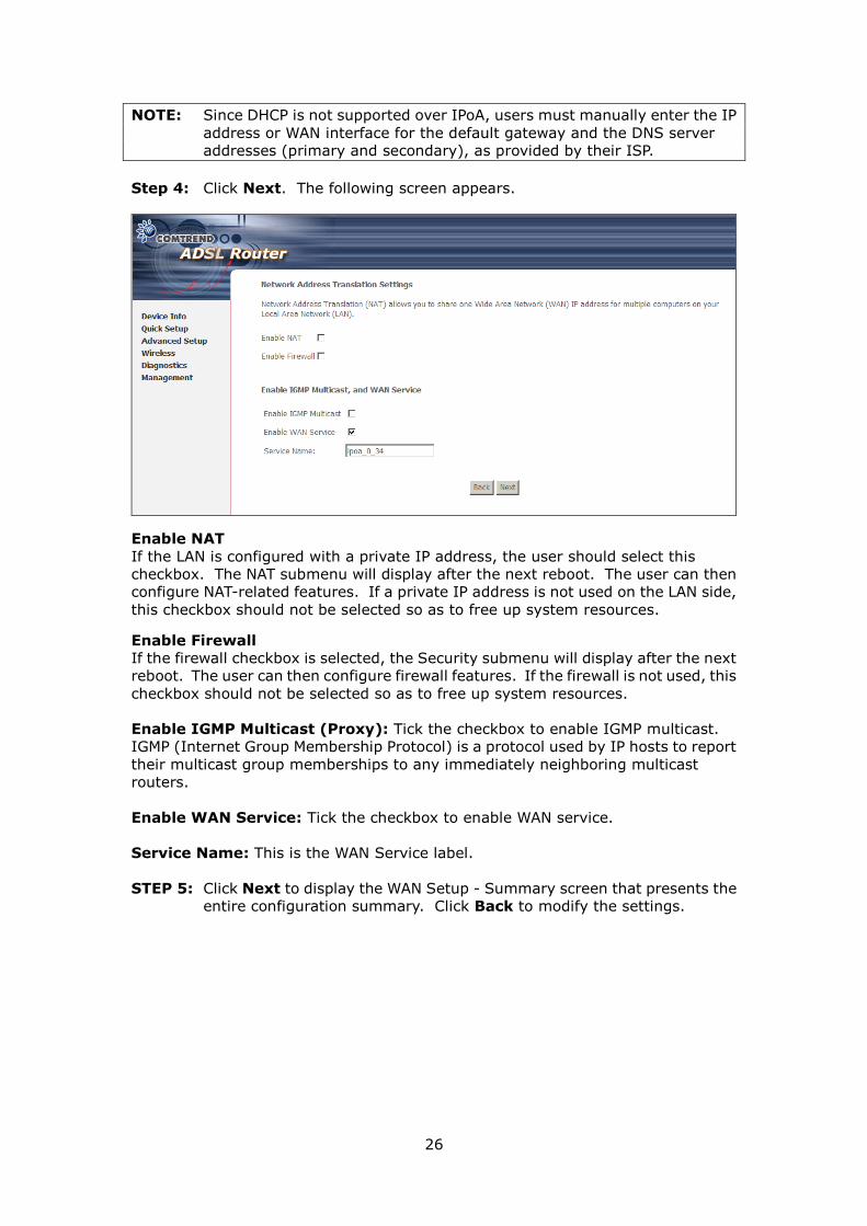
Enable NAT
If the LAN is configured with a private IP address, the user should select this
checkbox. The NAT submenu will display after the next reboot. The user can then
configure NAT-related features. If a private IP address is not used on the LAN side,
this checkbox should not be selected so as to free up system resources.
Enable Firewall
If the firewall checkbox is selected, the Security submenu will display after the next
reboot. The user can then configure firewall features. If the firewall is not used, this
checkbox should not be selected so as to free up system resources.
Enable IGMP Multicast (Proxy): Tick the checkbox to enable IGMP multicast.
IGMP (Internet Group Membership Protocol) is a protocol used by IP hosts to report
their multicast group memberships to any immediately neighboring multicast
routers.
Enable WAN Service: Tick the checkbox to enable WAN service.
Service Name: This is the WAN Service label.
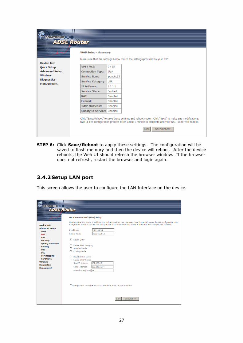
STEP 5: Click Next to display the WAN Setup - Summary screen that presents the
entire configuration summary. Click Back to modify the settings.
27
STEP 6: Click Save/Reboot to apply these settings. The configuration will be
saved to flash memory and then the device will reboot. After the device
reboots, the Web UI should refresh the browser window. If the browser
does not refresh, restart the browser and login again.
3.4.2 Setup LAN port
This screen allows the user to configure the LAN Interface on the device.
28
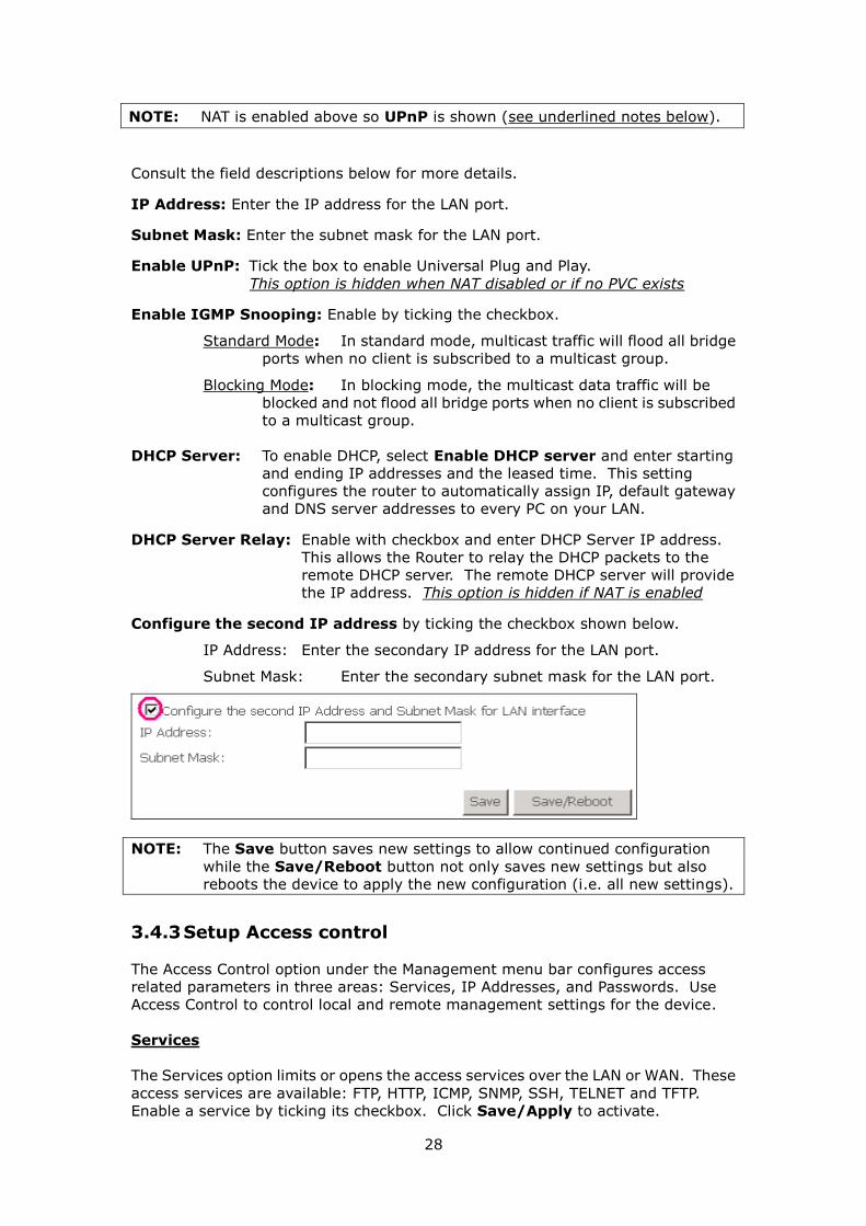
NOTE: NAT is enabled above so UPnP is shown (see underlined notes below).
Consult the field descriptions below for more details.
IP Address: Enter the IP address for the LAN port.
Subnet Mask: Enter the subnet mask for the LAN port.
Enable UPnP: Tick the box to enable Universal Plug and Play.
This option is hidden when NAT disabled or if no PVC exists
Enable IGMP Snooping: Enable by ticking the checkbox.
Standard Mode: In standard mode, multicast traffic will flood all bridge
ports when no client is subscribed to a multicast group.
Blocking Mode: In blocking mode, the multicast data traffic will be
blocked and not flood all bridge ports when no client is subscribed
to a multicast group.
DHCP Server: To enable DHCP, select Enable DHCP server and enter starting
and ending IP addresses and the leased time. This setting
configures the router to automatically assign IP, default gateway
and DNS server addresses to every PC on your LAN.
DHCP Server Relay: Enable with checkbox and enter DHCP Server IP address.
This allows the Router to relay the DHCP packets to the
remote DHCP server. The remote DHCP server will provide
the IP address. This option is hidden if NAT is enabled
Configure the second IP address by ticking the checkbox shown below.
IP Address: Enter the secondary IP address for the LAN port.
Subnet Mask: Enter the secondary subnet mask for the LAN port.
NOTE: The Save button saves new settings to allow continued configuration
while the Save/Reboot button not only saves new settings but also
reboots the device to apply the new configuration (i.e. all new settings).
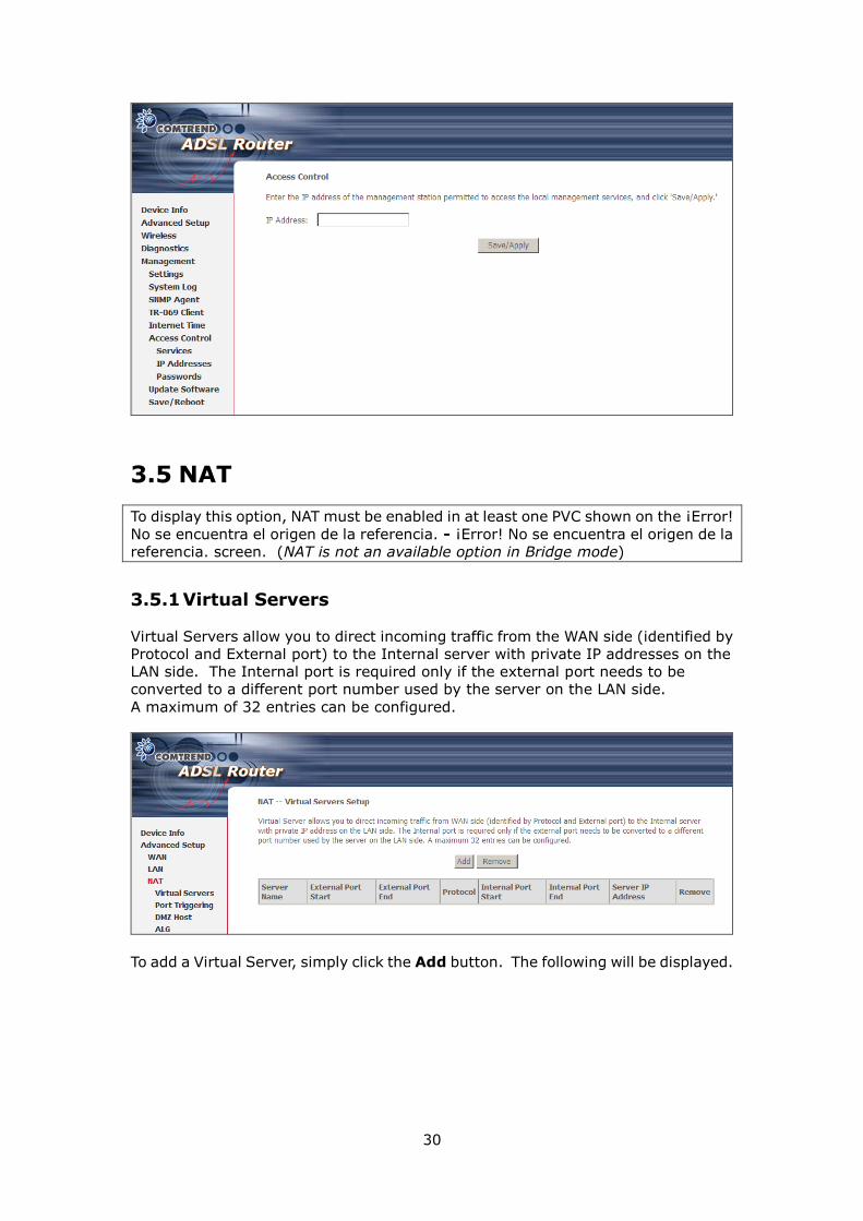
3.4.3 Setup Access control
The Access Control option under the Management menu bar configures access
related parameters in three areas: Services, IP Addresses, and Passwords. Use
Access Control to control local and remote management settings for the device.
Services
The Services option limits or opens the access services over the LAN or WAN. These
access services are available: FTP, HTTP, ICMP, SNMP, SSH, TELNET and TFTP.
Enable a service by ticking its checkbox. Click Save/Apply to activate.
29
NOTE: The WAN column is present if the WAN interface is active. Only the LAN
side will be displayed if the WAN interface is down.
IP Addresses
The IP Addresses option limits local access by IP address. When the Access
Control Mode is enabled, only the IP addresses listed here can access the device.
Before enabling Access Control Mode, add IP addresses with the Add button.
On this screen, enter the IP address, subnet mask, and interface to which you wish
to give management permissions. Click Save/Apply to continue.
30
3.5 NAT
To display this option, NAT must be enabled in at least one PVC shown on the ¡Error!
No se encuentra el origen de la referencia. - ¡Error! No se encuentra el origen de la
referencia. screen. (NAT is not an available option in Bridge mode)
3.5.1 Virtual Servers
Virtual Servers allow you to direct incoming traffic from the WAN side (identified by
Protocol and External port) to the Internal server with private IP addresses on the
LAN side. The Internal port is required only if the external port needs to be
converted to a different port number used by the server on the LAN side.
A maximum of 32 entries can be configured.
To add a Virtual Server, simply click the Add button. The following will be displayed.
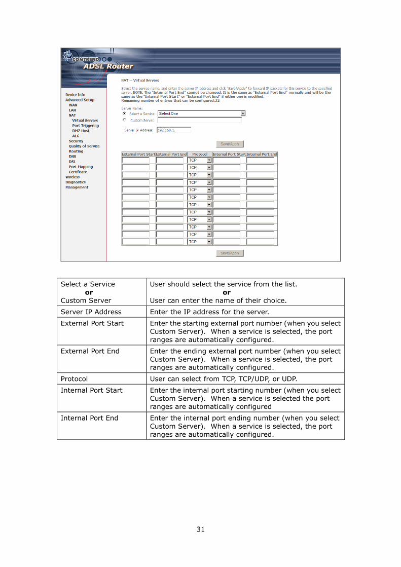
31
Select a Service
or
Custom Server
User should select the service from the list.
or
User can enter the name of their choice.
Server IP Address Enter the IP address for the server.
External Port Start Enter the starting external port number (when you select
Custom Server). When a service is selected, the port
ranges are automatically configured.
External Port End Enter the ending external port number (when you select
Custom Server). When a service is selected, the port
ranges are automatically configured.
Protocol User can select from TCP, TCP/UDP, or UDP.
Internal Port Start Enter the internal port starting number (when you select
Custom Server). When a service is selected the port
ranges are automatically configured
Internal Port End Enter the internal port ending number (when you select
Custom Server). When a service is selected, the port
ranges are automatically configured.
32
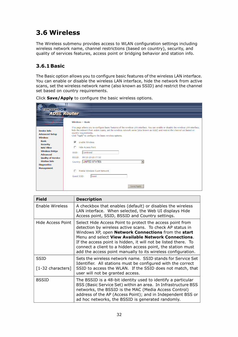
3.6 Wireless
The Wireless submenu provides access to WLAN configuration settings including
wireless network name, channel restrictions (based on country), security, and
quality of services features, access point or bridging behavior and station info.
3.6.1 Basic
The Basic option allows you to configure basic features of the wireless LAN interface.
You can enable or disable the wireless LAN interface, hide the network from active
scans, set the wireless network name (also known as SSID) and restrict the channel
set based on country requirements.
Click Save/Apply to configure the basic wireless options.
Field Description
Enable Wireless A checkbox that enables (default) or disables the wireless
LAN interface. When selected, the Web UI displays Hide
Access point, SSID, BSSID and Country settings.
Hide Access Point Select Hide Access Point to protect the access point from
detection by wireless active scans. To check AP status in
Windows XP, open Network Connections from the start
Menu and select View Available Network Connections.
If the access point is hidden, it will not be listed there. To
connect a client to a hidden access point, the station must
add the access point manually to its wireless configuration.
SSID
[1-32 characters]
Sets the wireless network name. SSID stands for Service Set
Identifier. All stations must be configured with the correct
SSID to access the WLAN. If the SSID does not match, that
user will not be granted access.
BSSID The BSSID is a 48-bit identity used to identify a particular
BSS (Basic Service Set) within an area. In Infrastructure BSS
networks, the BSSID is the MAC (Media Access Control)
address of the AP (Access Point); and in Independent BSS or
ad hoc networks, the BSSID is generated randomly.
33
Field Description
Country A drop-down menu that permits worldwide and specific
national settings. Each country listed below enforces specific
regulations limiting channel range:
US= worldwide
Japan=1-14
Jordan= 10-13
Israel= 1-13
Wireless
Guest
Network
The Guest SSID (Virtual Access Point) can be enabled by
selecting the Enable Wireless Guest Network checkbox.
Rename the Wireless Guest Network as you wish.
NOTE: Remote wireless hosts cannot scan Guest SSIDs.
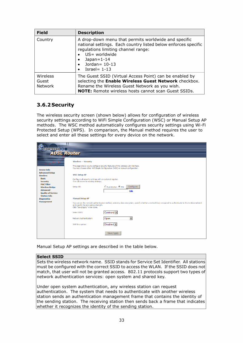
3.6.2 Security
The wireless security screen (shown below) allows for configuration of wireless
security settings according to WiFi Simple Configuration (WSC) or Manual Setup AP
methods. The WSC method automatically configures security settings using Wi-Fi
Protected Setup (WPS). In comparison, the Manual method requires the user to
select and enter all these settings for every device on the network.
Manual Setup AP settings are described in the table below.
Select SSID
Sets the wireless network name. SSID stands for Service Set Identifier. All stations
must be configured with the correct SSID to access the WLAN. If the SSID does not
match, that user will not be granted access. 802.11 protocols support two types of
network authentication services: open system and shared key.
Under open system authentication, any wireless station can request
authentication. The system that needs to authenticate with another wireless
station sends an authentication management frame that contains the identity of
the sending station. The receiving station then sends back a frame that indicates
whether it recognizes the identity of the sending station.
34
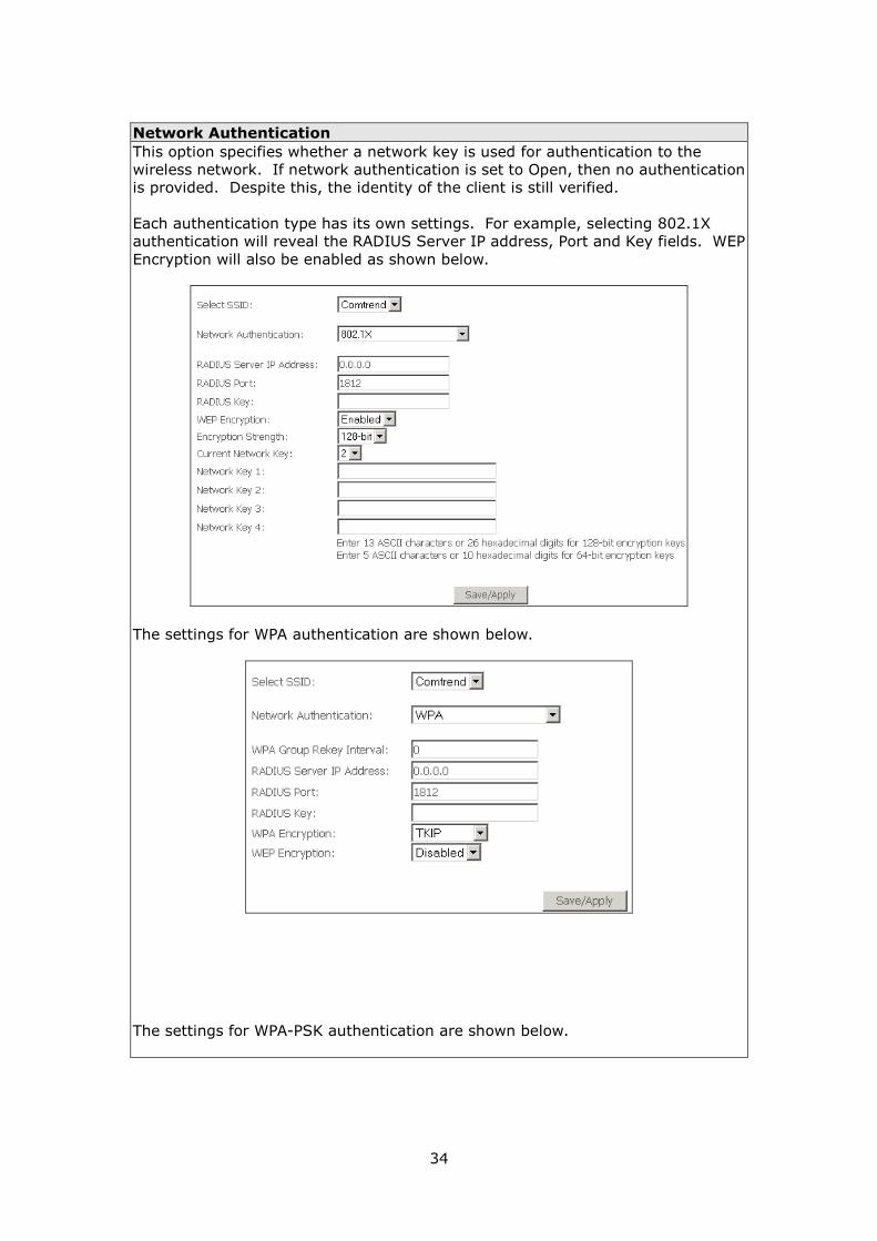
Network Authentication
This option specifies whether a network key is used for authentication to the
wireless network. If network authentication is set to Open, then no authentication
is provided. Despite this, the identity of the client is still verified.
Each authentication type has its own settings. For example, selecting 802.1X
authentication will reveal the RADIUS Server IP address, Port and Key fields. WEP
Encryption will also be enabled as shown below.
The settings for WPA authentication are shown below.
The settings for WPA-PSK authentication are shown below.

35
WEP Encryption
This option specifies whether data sent over the network is encrypted. The same
network key is used for data encryption and network authentication. Four network
keys can be defined although only one can be used at any one time. Use the Current
Network Key list box to select the appropriate network key.
Encryption Strength
This drop-down list box will display when WEP Encryption is enabled. The key
strength is proportional to the number of binary bits comprising the key. This
means that keys with a greater number of bits have a greater degree of security and
are considerably more difficult to crack. Encryption strength can be set to either
64-bit or 128-bit. A 64-bit key is equivalent to 5 ASCII characters or 10
hexadecimal numbers. A 128-bit key contains 13 ASCII characters or 26
hexadecimal numbers. FYI: Each key contains a 24-bit header (an initiation vector)
which enables parallel decoding of multiple streams of encrypted data.
WPS
WPS is an industry standard that simplifies wireless security setup for certified
network devices. Every WPS certified device has both a PIN number and a push
button, located on the device or accessed through device software. This router has
both a WPS button on the front panel and a virtual button accessed from the web
user interface (WUI).
Devices with the WPS logo
(shown here) support WPS.
However, the WPS logo might
not be present on your device.
In this case, check the device
documentation for the phrase
“Wi-Fi Protected Setup”.
NOTE: WPS is only available in WPA-PSK, WPA2-PSK or Mixed WPA2/WPA-PSK
network authentication modes. Other authentication modes do not use
WPS so they must be configured manually.
To configure security settings with WPS, follow the procedure below. You must
choose either the Push-Button or PIN configuration method for Steps 4 and 5.
I. SELECT NETWORK AUTHENTICATION MODE
36
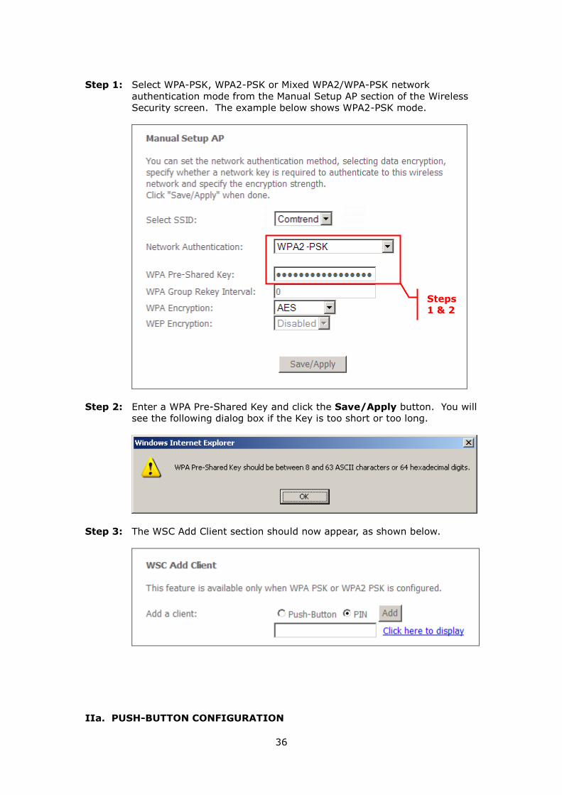
Step 1: Select WPA-PSK, WPA2-PSK or Mixed WPA2/WPA-PSK network
authentication mode from the Manual Setup AP section of the Wireless
Security screen. The example below shows WPA2-PSK mode.
Step 2: Enter a WPA Pre-Shared Key and click the Save/Apply button. You will
see the following dialog box if the Key is too short or too long.
Step 3: The WSC Add Client section should now appear, as shown below.
IIa. PUSH-BUTTON CONFIGURATION
Steps 1 & 2

37
The WPS push-button configuration provides a semi-automated configuration
method. The WPS button on the front panel of the router can be used for this
purpose or the Web User Interface (WUI) can be used exclusively.
The WPS push-button configuration is described in the procedure below. It is
assumed that the Wireless function is Enabled and that the router is configured as
the Wireless Access Point (AP) of your wireless LAN. In addition, the wireless client
must also be configured correctly and turned on, with WPS function enabled.
NOTE: The wireless AP on the router will search for WPS clients for 2 minutes. If
the router stops searching before you complete Step 5, then return to
Step 4 and try again.
Step 4: 1st method: WPS button
Press the WPS button on the front panel of the router. The WPS LED will
blink to show that the router has begun searching for WPS clients.
2nd method: WUI virtual button
From the WUI, select the Push-Button radio button in the WSC Add Client
section of the Wireless Security screen. Then click the Add button.
38
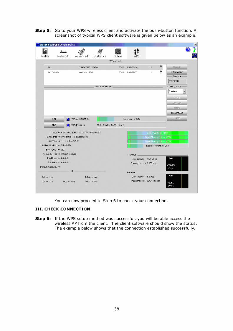
Step 5: Go to your WPS wireless client and activate the push-button function. A
screenshot of typical WPS client software is given below as an example.
You can now proceed to Step 6 to check your connection.
III. CHECK CONNECTION
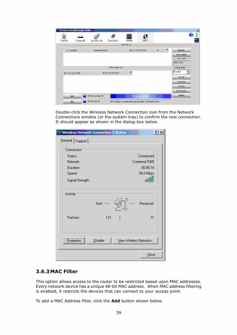
Step 6: If the WPS setup method was successful, you will be able access the
wireless AP from the client. The client software should show the status.
The example below shows that the connection established successfully.
39
Double-click the Wireless Network Connection icon from the Network
Connections window (or the system tray) to confirm the new connection.
It should appear as shown in the dialog-box below.
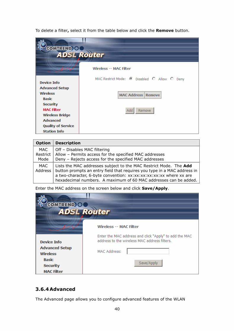
3.6.3 MAC Filter
This option allows access to the router to be restricted based upon MAC addresses.
Every network device has a unique 48-bit MAC address. When MAC address filtering
is enabled, it restricts the devices that can connect to your access point.
To add a MAC Address filter, click the Add button shown below.
40
To delete a filter, select it from the table below and click the Remove button.
Enter the MAC address on the screen below and click Save/Apply.
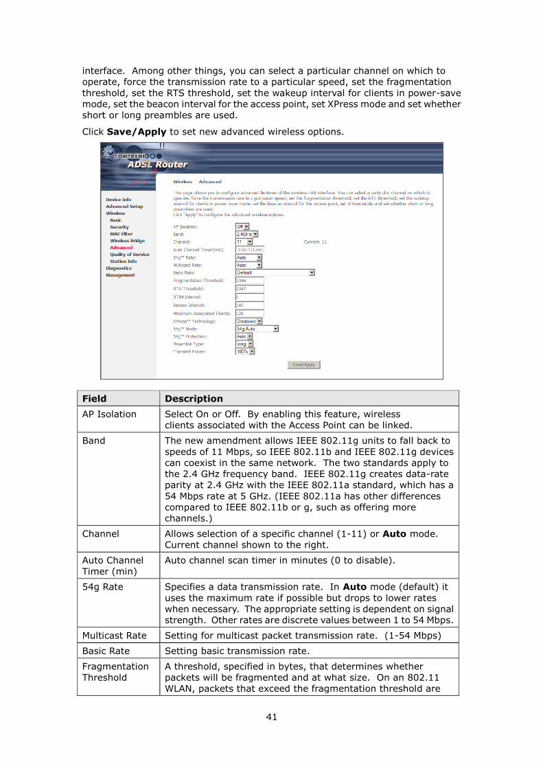
3.6.4 Advanced
The Advanced page allows you to configure advanced features of the WLAN
Option Description
MAC
Restrict
Mode
Off – Disables MAC filtering
Allow – Permits access for the specified MAC addresses
Deny – Rejects access for the specified MAC addresses
MAC
Address
Lists the MAC addresses subject to the MAC Restrict Mode. The Add
button prompts an entry field that requires you type in a MAC address in
a two-character, 6-byte convention: xx:xx:xx:xx:xx:xx where xx are
hexadecimal numbers. A maximum of 60 MAC addresses can be added.
41
interface. Among other things, you can select a particular channel on which to
operate, force the transmission rate to a particular speed, set the fragmentation
threshold, set the RTS threshold, set the wakeup interval for clients in power-save
mode, set the beacon interval for the access point, set XPress mode and set whether
short or long preambles are used.
Click Save/Apply to set new advanced wireless options.
Field Description
AP Isolation Select On or Off. By enabling this feature, wireless
clients associated with the Access Point can be linked.
Band The new amendment allows IEEE 802.11g units to fall back to
speeds of 11 Mbps, so IEEE 802.11b and IEEE 802.11g devices
can coexist in the same network. The two standards apply to
the 2.4 GHz frequency band. IEEE 802.11g creates data-rate
parity at 2.4 GHz with the IEEE 802.11a standard, which has a
54 Mbps rate at 5 GHz. (IEEE 802.11a has other differences
compared to IEEE 802.11b or g, such as offering more
channels.)
Channel Allows selection of a specific channel (1-11) or Auto mode.
Current channel shown to the right.
Auto Channel
Timer (min)
Auto channel scan timer in minutes (0 to disable).
54g Rate Specifies a data transmission rate. In Auto mode (default) it
uses the maximum rate if possible but drops to lower rates
when necessary. The appropriate setting is dependent on signal
strength. Other rates are discrete values between 1 to 54 Mbps.
Multicast Rate Setting for multicast packet transmission rate. (1-54 Mbps)
Basic Rate Setting basic transmission rate.
Fragmentation
Threshold
A threshold, specified in bytes, that determines whether
packets will be fragmented and at what size. On an 802.11
WLAN, packets that exceed the fragmentation threshold are
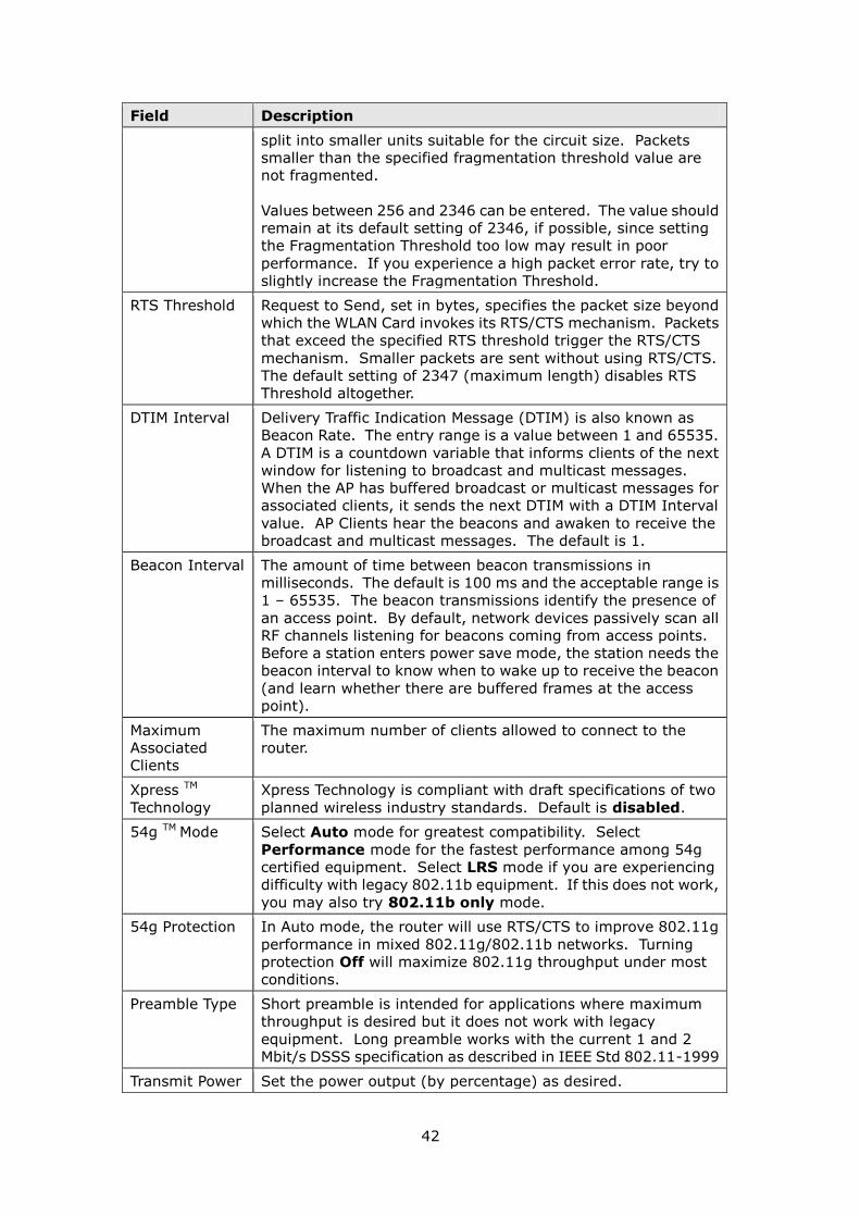
42
Field Description
split into smaller units suitable for the circuit size. Packets
smaller than the specified fragmentation threshold value are
not fragmented.
Values between 256 and 2346 can be entered. The value should
remain at its default setting of 2346, if possible, since setting
the Fragmentation Threshold too low may result in poor
performance. If you experience a high packet error rate, try to
slightly increase the Fragmentation Threshold.
RTS Threshold Request to Send, set in bytes, specifies the packet size beyond
which the WLAN Card invokes its RTS/CTS mechanism. Packets
that exceed the specified RTS threshold trigger the RTS/CTS
mechanism. Smaller packets are sent without using RTS/CTS.
The default setting of 2347 (maximum length) disables RTS
Threshold altogether.
DTIM Interval Delivery Traffic Indication Message (DTIM) is also known as
Beacon Rate. The entry range is a value between 1 and 65535.
A DTIM is a countdown variable that informs clients of the next
window for listening to broadcast and multicast messages.
When the AP has buffered broadcast or multicast messages for
associated clients, it sends the next DTIM with a DTIM Interval
value. AP Clients hear the beacons and awaken to receive the
broadcast and multicast messages. The default is 1.
Beacon Interval The amount of time between beacon transmissions in
milliseconds. The default is 100 ms and the acceptable range is
1 – 65535. The beacon transmissions identify the presence of
an access point. By default, network devices passively scan all
RF channels listening for beacons coming from access points.
Before a station enters power save mode, the station needs the
beacon interval to know when to wake up to receive the beacon
(and learn whether there are buffered frames at the access
point).
Maximum
Associated
Clients
The maximum number of clients allowed to connect to the
router.
Xpress TM
Technology
Xpress Technology is compliant with draft specifications of two
planned wireless industry standards. Default is disabled.
54g TM Mode Select Auto mode for greatest compatibility. Select
Performance mode for the fastest performance among 54g
certified equipment. Select LRS mode if you are experiencing
difficulty with legacy 802.11b equipment. If this does not work,
you may also try 802.11b only mode.
54g Protection In Auto mode, the router will use RTS/CTS to improve 802.11g
performance in mixed 802.11g/802.11b networks. Turning
protection Off will maximize 802.11g throughput under most
conditions.
Preamble Type Short preamble is intended for applications where maximum
throughput is desired but it does not work with legacy
equipment. Long preamble works with the current 1 and 2
Mbit/s DSSS specification as described in IEEE Std 802.11-1999
Transmit Power Set the power output (by percentage) as desired.
43
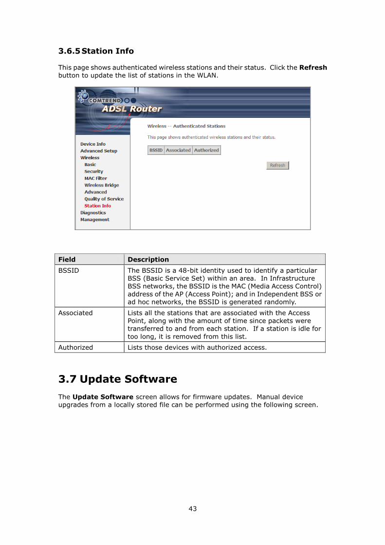
3.6.5 Station Info
This page shows authenticated wireless stations and their status. Click the Refresh
button to update the list of stations in the WLAN.
Field Description
BSSID The BSSID is a 48-bit identity used to identify a particular
BSS (Basic Service Set) within an area. In Infrastructure
BSS networks, the BSSID is the MAC (Media Access Control)
address of the AP (Access Point); and in Independent BSS or
ad hoc networks, the BSSID is generated randomly.
Associated Lists all the stations that are associated with the Access
Point, along with the amount of time since packets were
transferred to and from each station. If a station is idle for
too long, it is removed from this list.
Authorized Lists those devices with authorized access.
3.7 Update Software
The Update Software screen allows for firmware updates. Manual device
upgrades from a locally stored file can be performed using the following screen.

44
Step 1: Obtain an updated software image file from your ISP.
Step 2: Enter the path and filename of the firmware image file in the Software
File Name field or click the Browse button to locate the image file.
Step 3: Click the Update Software button once to upload and install the file.
NOTE: The update process will take about 2 minutes to complete. The device will
reboot and the browser window will refresh to the default screen upon successful
installation.
NOTE: It is recommended that you compare the Software Version at the top of
the Device Info Summary screen (see graphic below) with the firmware version
installed, to confirm the installation was successful.
3.8 Save and Reboot
This function saves the current configuration settings and reboots the device.
NOTE: You may need to reconfigure the TCP/IP settings after rebooting. For
example, if the DHCP server is disabled Static IP settings must be configured.
NOTE: If you lose all access to the web user interface (WUI), you may need to close
the browser, wait for two minutes, and then restart the WUI.
If this does not work, then press the reset button on the rear panel of the
device for 5-7 seconds to restore to default settings.