Embed Size (px)
Citation preview
Walt Disney World Swan and Dolphin ResortOrlando, Florida
12/1/2005 - 8:00 am - 11:30 am Room:N. Hemispheres (Salon B/C) (Dolphin)
Advanced Autodesk® Revit® Building Techniques
This extended session is designed for all Revit users who want to explore different modeling techniques for creating some very common but tricky Revit objects. Learn how you can use different modeling methods to achieve the same end result. Rather than teaching a major concept of a specific functionality, we will discuss many interesting and useful topics, including some tips and tricks, and possible workarounds to overcome some modeling limitations.
BD41-1
About the Speaker:
Greg Demchak - AutodeskLillian Smith, A.I.A.; Wai-Ming Chuand
Greg has been working on the Revit product for the last 5 years as a software analyst, providing critical insight into the quality and design of the application. Before joining the Revit team, Greg attended MIT where he earned a Masters degree in architecture. He has also been teaching Revit at the Boston Architecturual Center for the last 3 [email protected]
Lilli is an architect and product designer for the Revit platform in Waltham, MA. She has over 4 years of experience working with Revit through various roles including Product Design, QA, and Customer Success where she worked closely with many customers on problem solving and strategic project planning. Lilli has a master’s degree in architecture from Harvard and is a licensed architect with over 5 years of experience in professional practice. Wai-Ming has worked with the Revit support team for over 5 years, and most recently as a Revit project consultant in Autodesk's Building Solutions division. Fluent in English, French, and Chinese, he has been providing technical support, training, and implementation of Revit to customers in the U.S., Canada, Europe, and China . Prior to joining Revit, he was an architectural designer at a firm in Montreal, Canada specializing in retail redevelopment and real-estate planning services. Wai-Ming holds Bachelor of Science and Bachelor of Architecture degrees from McGill University in [email protected]

BD41-1 Advanced Autodesk® Revit® Techniques
2
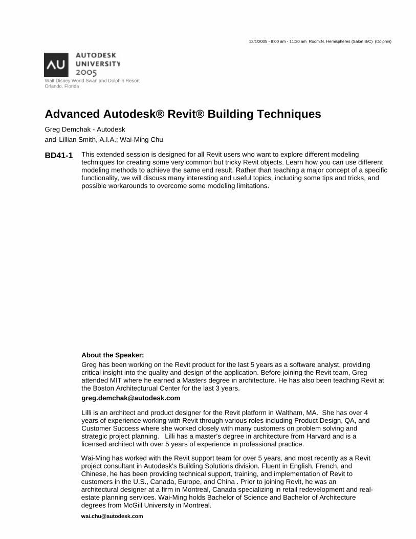
1 Curtain Walls/Storefront
Figure 1: Curtain wall variations
Introduction
Curtain walls provide an incredible amount of flexibility and can be constructed with relative ease using a matrix of parameters and components. (Figure 1) From standard store front to complex glazing systems, using Autodesk Revit Building provides tools to let you explore and design for a wide range of façade types.
When thinking of a curtain wall system, we need to think about three primary components: Grids, Mullions, and Panels. Each of these objects interrelates to one another in explicit, logical ways so that making changes to the system requires minimal fidgeting with edge conditions between objects. In other words, a change to one object will ripple through the system and automatically update the model. Adjusting grid lines will automatically update the size and position of mullions and panels. Like many objects in Revit Building, the concept of a host element is used to drive change through a hierarchy of objects. In a curtain wall system, the wall face hosts curtain grids, which in turn host mullions. The third component, Panels, dynamically fill in space between grids and mullions.
Looking at type properties, we see that curtain walls can be defined by vertical and horizontal grid patterns, border and internal mullions types, and curtain panels. Grid Patterns establish a spacing format for the wall in two primary directions. For curtain walls, these are the Horizontal and Vertical grids. For curtain systems, these are referred to as Grid 1 and Grid 2.
Mullions and panels can also be defined in the type properties, speeding up the process of layout design. The components are built on the fly as curtain walls are drawn and/or changed. For example, if we make a curtain wall longer, such that new grids are generated, additional mullions and panels will be generated.
Selection
Mullion and panel selection is made easier by using the right-click context menu. When your mouse is over a panel or mullion, right-click to bring up options for selection based on internal grids, boundary grids, or the entire wall face. If you need to change an entire row of panels this speeds up the interaction tremendously. Note that to change panels that are defined in the type you need to first unpin the object. If multiple objects are selected that have their identity pinned down in the type, use the edit menu command, Unpin Position to free them up.
Grids
Grids are the bones of any curtain system; the matrix off which all subcomponents are suspended. Using type-
BD41-1 Advanced Autodesk® Revit® Techniques
3
defined grid patterns, curtain walls can be generated very rapidly. Layout rules allow you experiment with spacing without having to manually manage individual grid locations.
Layout rules for Fixed Distance, Fixed Number, and Maximum Spacing are provided. When fixed distance is set, a spacing value will place a grid at that interval. Fixed number distributes grids across the wall based on a desired number of divisions. Maximum spacing distributes grids based on spacing, but spread the pattern to fit if the length of the wall is not a multiple of the spacing value.
Additional grids can be added to a type-driven curtain system my placing them manually on the curtain wall face. This allows you to define a major grid pattern and then further refine the pattern with additional grids. Place grids using the Curtain Grid tool in the Modeling design pane to achieve A-B-A patterns.
Each grid pattern can be rotated on the host face. To rotate a grid, edit the Angle instance parameters in properties dialog, or select the face of the curtain wall, and press the curtain wall icon to edit the grid configuration. Typing in values in the active blue text fields will change the angle of the grids.
Mullions
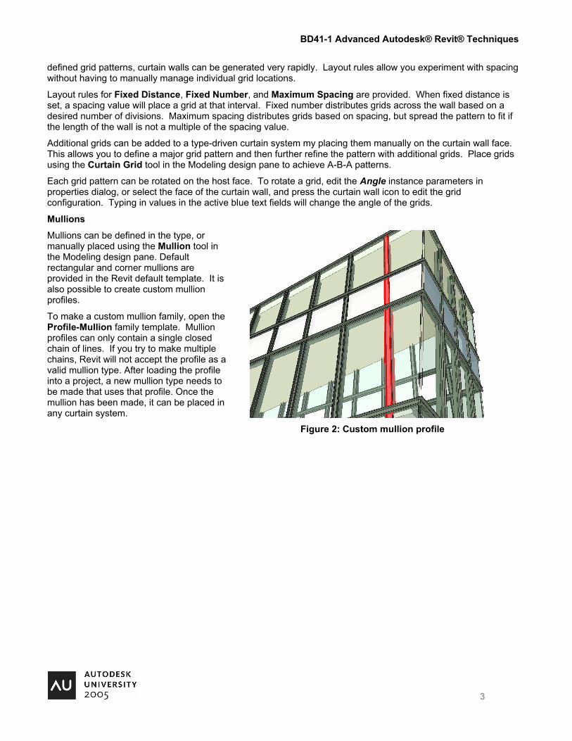
Mullions can be defined in the type, or manually placed using the Mullion tool in the Modeling design pane. Default rectangular and corner mullions are provided in the Revit default template. It is also possible to create custom mullion profiles.
To make a custom mullion family, open the Profile-Mullion family template. Mullion profiles can only contain a single closed chain of lines. If you try to make multiple chains, Revit will not accept the profile as a valid mullion type. After loading the profile into a project, a new mullion type needs to be made that uses that profile. Once the mullion has been made, it can be placed in any curtain system.
Figure 2: Custom mullion profile
BD41-1 Advanced Autodesk® Revit® Techniques
4
Panels
Panels fill in the space between grids and mullions, and can be virtually any shape. Like grids and mullions, a default panel can be defined in the type properties. Panels can be swapped out with any other curtain panels or wall types. If basic wall types are used as panel, then the wall panel operates like any other wall in Revit and can host inserts.
A useful, albeit rather hidden parameter, automatically embed, allows a curtain wall to cut out geometry from basic walls. With this parameter enabled, it is not necessary to edit elevation profile sketches to keep two walls from overlapping. You can place a curtain wall, and sketch other walls right on top of it. No overlap warning will be issued, and the wall will be carved out perfectly.
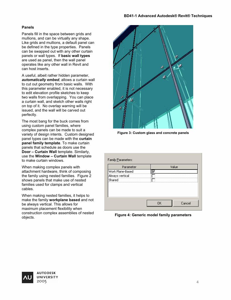
The most bang for the buck comes from using custom panel families, where complex panels can be made to suit a variety of design intents. Custom designed panel types can be made with the curtain panel family template. To make curtain panels that schedule as doors use the Door – Curtain Wall template. Similarly, use the Window – Curtain Wall template to make curtain windows.
When making complex panels with attachment hardware, think of composing the family using nested families. Figure 2 shows panels that make use of nested families used for clamps and vertical cables.
When making nested families, it helps to make the family workplane based and not be always vertical. This allows for maximum placement flexibility when construction complex assemblies of nested objects.
Figure 3: Custom glass and concrete panels
Figure 4: Generic model family parameters
BD41-1 Advanced Autodesk® Revit® Techniques
5
2 Stairs and Railings Stairs
Revit provides a sketch based tool for creating stairs. This means that stairs are limited to boundaries that can be sketched in one plan view. However, by manipulating type and instance properties and combining more than one stair, a wide variety of stairs can be constructed.
Winder Stairs
Alignment snaps can be very helpful when creating stairs that turn corners. These snaps will help orient the stair correctly around the corner for the given width. Remember that the run line is drawn at ½ the specified width of the stair. To add winders, add diagonal riser lines at the point where the stair turns. Split the boundary line wherever you want the stringer to change slope. You can further control the stringer through the option bar – for example, you can set segments to be flat or sloped, or have an offset.
Spiral Stairs
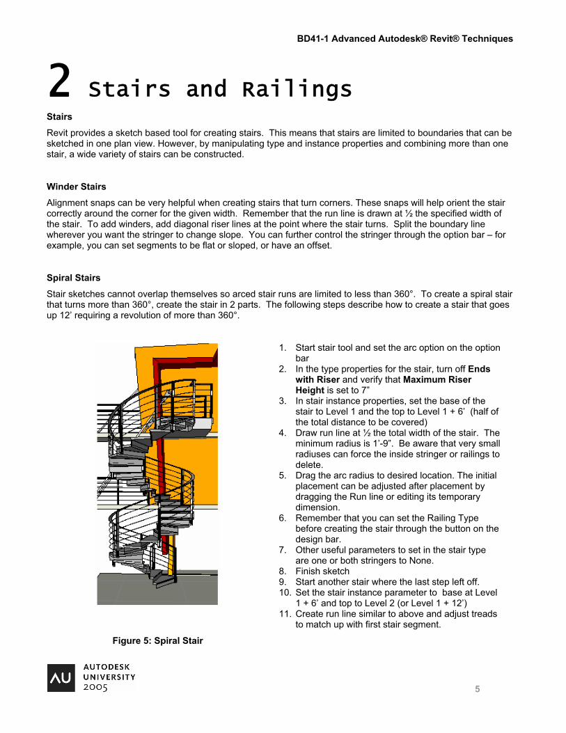
Stair sketches cannot overlap themselves so arced stair runs are limited to less than 360°. To create a spiral stair that turns more than 360°, create the stair in 2 parts. The following steps describe how to create a stair that goes up 12’ requiring a revolution of more than 360°.
1. Start stair tool and set the arc option on the option bar
2. In the type properties for the stair, turn off Ends with Riser and verify that Maximum Riser Height is set to 7”
3. In stair instance properties, set the base of the stair to Level 1 and the top to Level 1 + 6’ (half of the total distance to be covered)
4. Draw run line at ½ the total width of the stair. The minimum radius is 1’-9”. Be aware that very small radiuses can force the inside stringer or railings to delete.
5. Drag the arc radius to desired location. The initial placement can be adjusted after placement by dragging the Run line or editing its temporary dimension.
6. Remember that you can set the Railing Type before creating the stair through the button on the design bar.
7. Other useful parameters to set in the stair type are one or both stringers to None.
8. Finish sketch 9. Start another stair where the last step left off. 10. Set the stair instance parameter to base at Level
1 + 6’ and top to Level 2 (or Level 1 + 12’) 11. Create run line similar to above and adjust treads
to match up with first stair segment.
Figure 5: Spiral Stair
BD41-1 Advanced Autodesk® Revit® Techniques
6
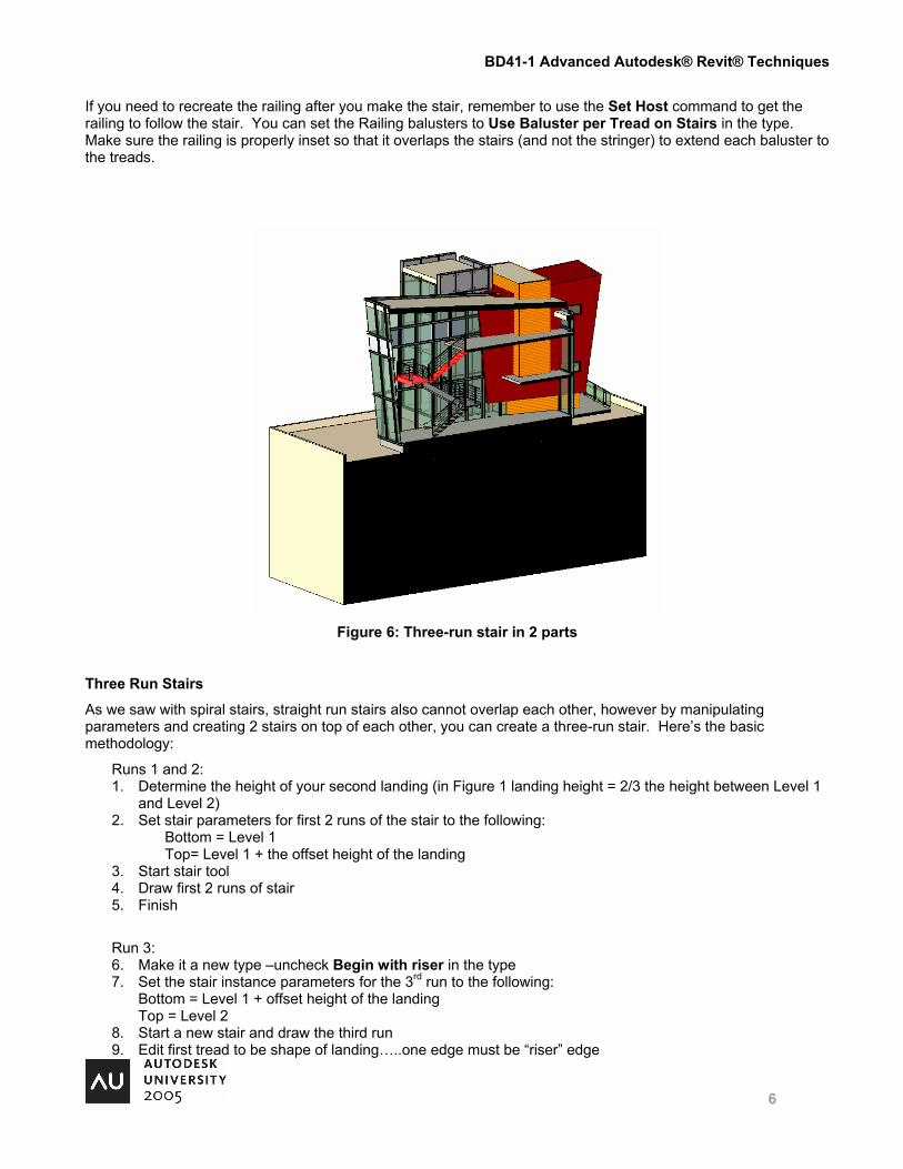
If you need to recreate the railing after you make the stair, remember to use the Set Host command to get the railing to follow the stair. You can set the Railing balusters to Use Baluster per Tread on Stairs in the type. Make sure the railing is properly inset so that it overlaps the stairs (and not the stringer) to extend each baluster to the treads.
Figure 6: Three-run stair in 2 parts
Three Run Stairs
As we saw with spiral stairs, straight run stairs also cannot overlap each other, however by manipulating parameters and creating 2 stairs on top of each other, you can create a three-run stair. Here’s the basic methodology:
Runs 1 and 2: 1. Determine the height of your second landing (in Figure 1 landing height = 2/3 the height between Level 1
and Level 2) 2. Set stair parameters for first 2 runs of the stair to the following:
Bottom = Level 1 Top= Level 1 + the offset height of the landing
3. Start stair tool 4. Draw first 2 runs of stair 5. Finish
Run 3: 6. Make it a new type –uncheck Begin with riser in the type 7. Set the stair instance parameters for the 3rd run to the following:
Bottom = Level 1 + offset height of the landing Top = Level 2
8. Start a new stair and draw the third run 9. Edit first tread to be shape of landing…..one edge must be “riser” edge
BD41-1 Advanced Autodesk® Revit® Techniques
7
10. Set all boundaries of this tread to ‘flat’----in option bar 11. Finish sketch 12. Edit rails to correct shape….set to flat- in option bar in sketch 13. Finish rails 14. Landing stringers will be too high - edit the stair sketch and use – “height correction” in option bar to lower
them 15. In stair type use “extend below base” parameter to set bottom of stringer (negative number is down)
Railings
Revit provides tools for creating complex railing designs using a combination of layout patterns, profiles, balusters, and panels. The dialog for railing layout can appear daunting, but can in fact be understood.
Balusters
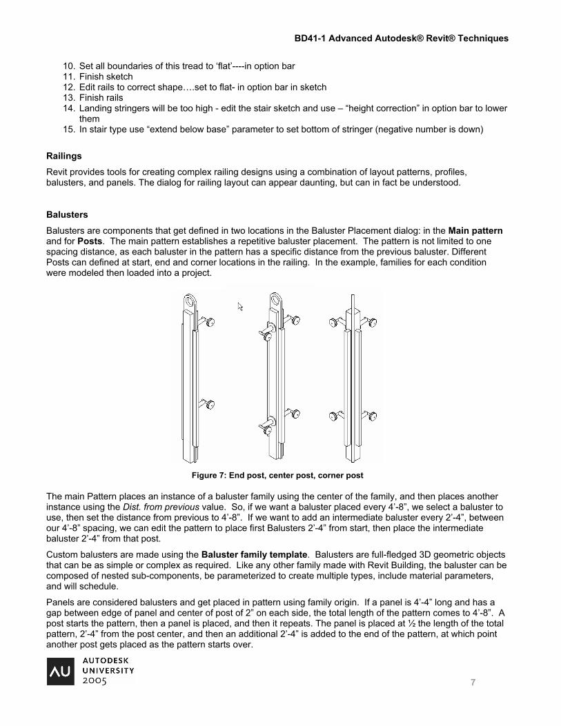
Balusters are components that get defined in two locations in the Baluster Placement dialog: in the Main pattern and for Posts. The main pattern establishes a repetitive baluster placement. The pattern is not limited to one spacing distance, as each baluster in the pattern has a specific distance from the previous baluster. Different Posts can defined at start, end and corner locations in the railing. In the example, families for each condition were modeled then loaded into a project.
Figure 7: End post, center post, corner post
The main Pattern places an instance of a baluster family using the center of the family, and then places another instance using the Dist. from previous value. So, if we want a baluster placed every 4’-8”, we select a baluster to use, then set the distance from previous to 4’-8”. If we want to add an intermediate baluster every 2’-4”, between our 4’-8” spacing, we can edit the pattern to place first Balusters 2’-4” from start, then place the intermediate baluster 2’-4” from that post.
Custom balusters are made using the Baluster family template. Balusters are full-fledged 3D geometric objects that can be as simple or complex as required. Like any other family made with Revit Building, the baluster can be composed of nested sub-components, be parameterized to create multiple types, include material parameters, and will schedule.
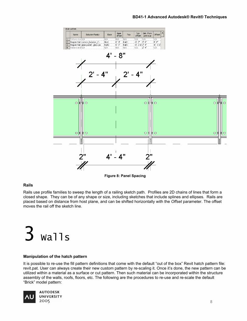
Panels are considered balusters and get placed in pattern using family origin. If a panel is 4’-4” long and has a gap between edge of panel and center of post of 2” on each side, the total length of the pattern comes to 4’-8”. A post starts the pattern, then a panel is placed, and then it repeats. The panel is placed at ½ the length of the total pattern, 2’-4” from the post center, and then an additional 2’-4” is added to the end of the pattern, at which point another post gets placed as the pattern starts over.
BD41-1 Advanced Autodesk® Revit® Techniques
8
Figure 8: Panel Spacing
Rails
Rails use profile families to sweep the length of a railing sketch path. Profiles are 2D chains of lines that form a closed shape. They can be of any shape or size, including sketches that include splines and ellipses. Rails are placed based on distance from host plane, and can be shifted horizontally with the Offset parameter. The offset moves the rail off the sketch line.
3 Walls
Manipulation of the hatch pattern
It is possible to re-use the fill pattern definitions that come with the default “out of the box” Revit hatch pattern file: revit.pat. User can always create their new custom pattern by re-scaling it. Once it’s done, the new pattern can be utilized within a material as a surface or cut pattern. Then such material can be incorporated within the structure assembly of the walls, roofs, floors, etc. The following are the procedures to re-use and re-scale the default “Brick” model pattern:
BD41-1 Advanced Autodesk® Revit® Techniques
9
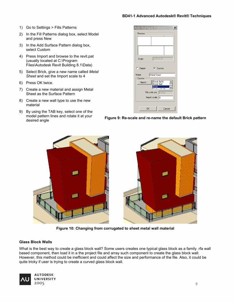
1) Go to Settings > Fills Patterns
2) In the Fill Patterns dialog box, select Model and press New
3) In the Add Surface Pattern dialog box, select Custom
4) Press Import and browse to the revit.pat (usually located at C:\Program Files\Autodesk Revit Building 8.1\Data)
5) Select Brick, give a new name called Metal Sheet and set the Import scale to 4
6) Press OK twice.
7) Create a new material and assign Metal Sheet as the Surface Pattern
8) Create a new wall type to use the new material
9) By using the TAB key, select one of the model pattern lines and rotate it at your desired angle
Figure 9: Re-scale and re-name the default Brick pattern
Figure 10: Changing from corrugated to sheet metal wall material
Glass Block Walls
What is the best way to create a glass block wall? Some users creates one typical glass block as a family .rfa wall based component, then load it in a the project file and array such component to create the glass block wall. However, this method could be inefficient and could affect the size and performance of the file. Also, it could be quite tricky if user is trying to create a curved glass block wall.
BD41-1 Advanced Autodesk® Revit® Techniques
10
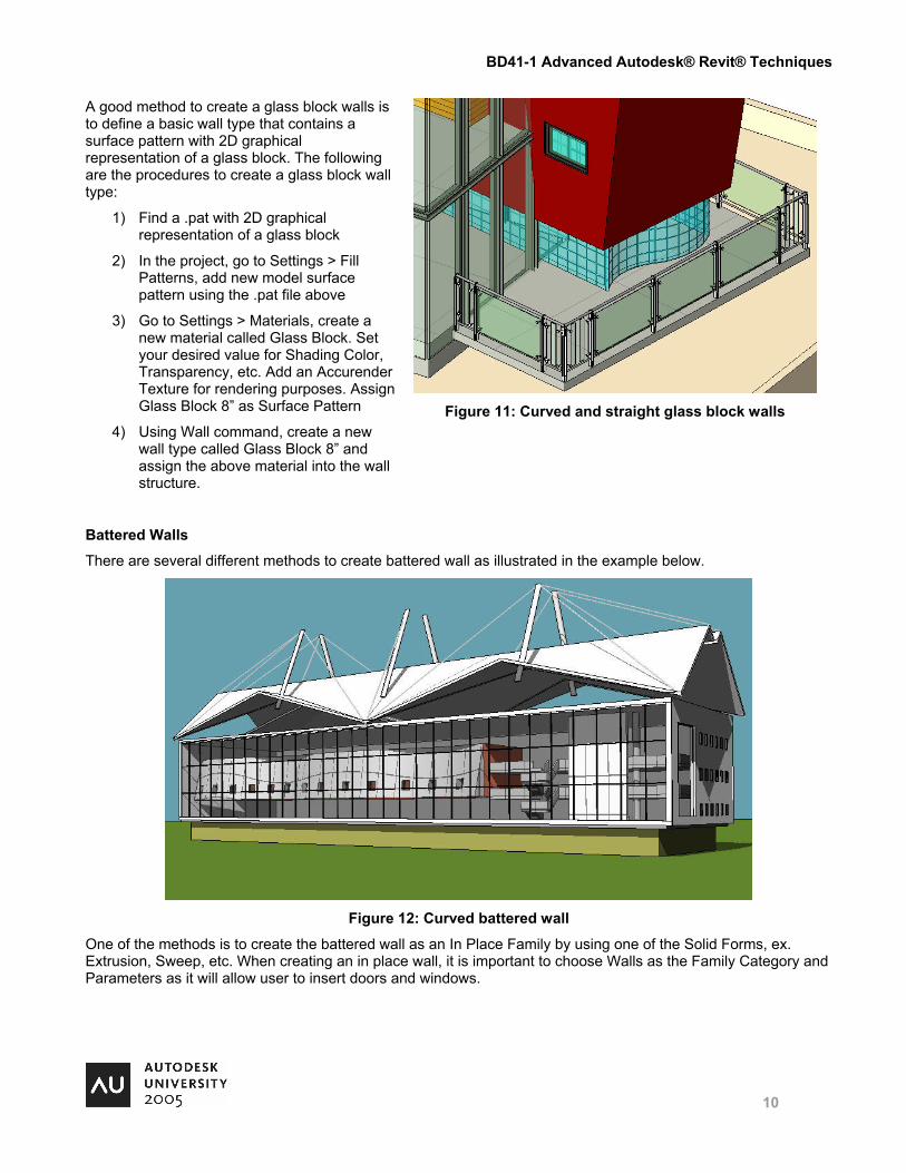
A good method to create a glass block walls is to define a basic wall type that contains a surface pattern with 2D graphical representation of a glass block. The following are the procedures to create a glass block wall type:
1) Find a .pat with 2D graphical representation of a glass block
2) In the project, go to Settings > Fill Patterns, add new model surface pattern using the .pat file above
3) Go to Settings > Materials, create a new material called Glass Block. Set your desired value for Shading Color, Transparency, etc. Add an Accurender Texture for rendering purposes. Assign Glass Block 8” as Surface Pattern
4) Using Wall command, create a new wall type called Glass Block 8” and assign the above material into the wall structure.
Figure 11: Curved and straight glass block walls
Battered Walls
There are several different methods to create battered wall as illustrated in the example below.
Figure 12: Curved battered wall
One of the methods is to create the battered wall as an In Place Family by using one of the Solid Forms, ex. Extrusion, Sweep, etc. When creating an in place wall, it is important to choose Walls as the Family Category and Parameters as it will allow user to insert doors and windows.
BD41-1 Advanced Autodesk® Revit® Techniques
11
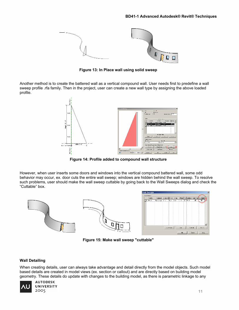
Figure 13: In Place wall using solid sweep
Another method is to create the battered wall as a vertical compound wall. User needs first to predefine a wall sweep profile .rfa family. Then in the project, user can create a new wall type by assigning the above loaded profile.
Figure 14: Profile added to compound wall structure
However, when user inserts some doors and windows into the vertical compound battered wall, some odd behavior may occur, ex. door cuts the entire wall sweep; windows are hidden behind the wall sweep. To resolve such problems, user should make the wall sweep cuttable by going back to the Wall Sweeps dialog and check the “Cuttable” box.
Figure 15: Make wall sweep "cuttable"
Wall Detailing
When creating details, user can always take advantage and detail directly from the model objects. Such model based details are created in model views (ex. section or callout) and are directly based on building model geometry. These details do update with changes to the building model, as there is parametric linkage to any
BD41-1 Advanced Autodesk® Revit® Techniques
12
building model components. If necessary, user can always add some detail components to complete the details with more accuracy.
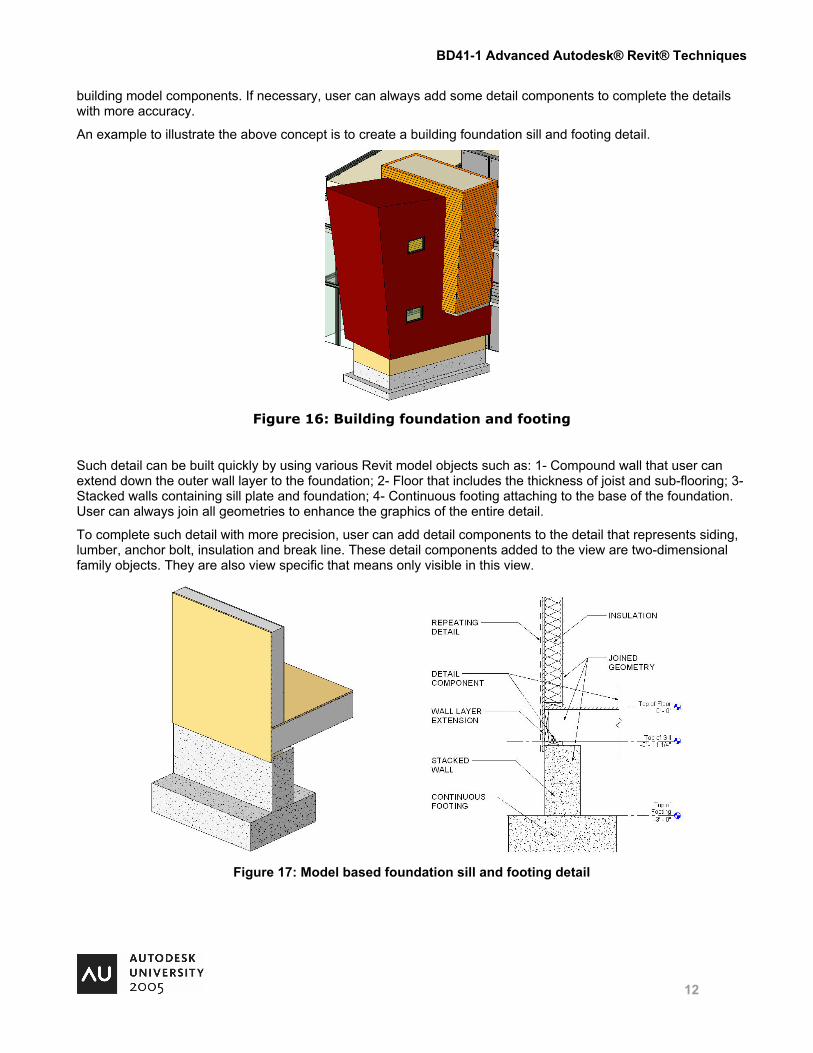
An example to illustrate the above concept is to create a building foundation sill and footing detail.
Figure 16: Building foundation and footing
Such detail can be built quickly by using various Revit model objects such as: 1- Compound wall that user can extend down the outer wall layer to the foundation; 2- Floor that includes the thickness of joist and sub-flooring; 3- Stacked walls containing sill plate and foundation; 4- Continuous footing attaching to the base of the foundation. User can always join all geometries to enhance the graphics of the entire detail.
To complete such detail with more precision, user can add detail components to the detail that represents siding, lumber, anchor bolt, insulation and break line. These detail components added to the view are two-dimensional family objects. They are also view specific that means only visible in this view.
Figure 17: Model based foundation sill and footing detail
BD41-1 Advanced Autodesk® Revit® Techniques
13
4 Roofs Roofs that slope to one point
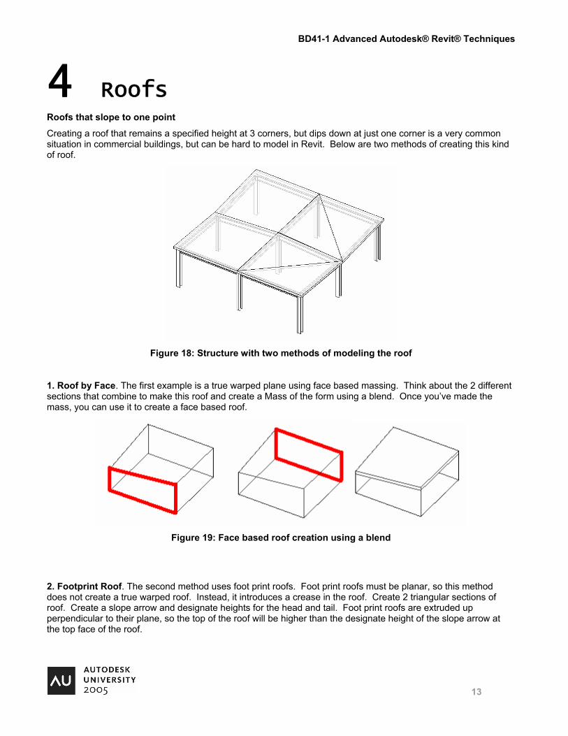
Creating a roof that remains a specified height at 3 corners, but dips down at just one corner is a very common situation in commercial buildings, but can be hard to model in Revit. Below are two methods of creating this kind of roof.
Figure 18: Structure with two methods of modeling the roof
1. Roof by Face. The first example is a true warped plane using face based massing. Think about the 2 different sections that combine to make this roof and create a Mass of the form using a blend. Once you’ve made the mass, you can use it to create a face based roof.
Figure 19: Face based roof creation using a blend
2. Footprint Roof. The second method uses foot print roofs. Foot print roofs must be planar, so this method does not create a true warped roof. Instead, it introduces a crease in the roof. Create 2 triangular sections of roof. Create a slope arrow and designate heights for the head and tail. Foot print roofs are extruded up perpendicular to their plane, so the top of the roof will be higher than the designate height of the slope arrow at the top face of the roof.
BD41-1 Advanced Autodesk® Revit® Techniques
14
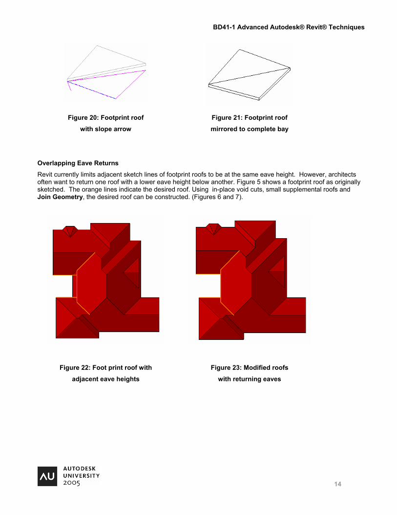
Figure 20: Footprint roof
with slope arrow
Figure 21: Footprint roof
mirrored to complete bay
Overlapping Eave Returns
Revit currently limits adjacent sketch lines of footprint roofs to be at the same eave height. However, architects often want to return one roof with a lower eave height below another. Figure 5 shows a footprint roof as originally sketched. The orange lines indicate the desired roof. Using in-place void cuts, small supplemental roofs and Join Geometry, the desired roof can be constructed. (Figures 6 and 7).
Figure 22: Foot print roof with
adjacent eave heights
Figure 23: Modified roofs
with returning eaves
BD41-1 Advanced Autodesk® Revit® Techniques
15
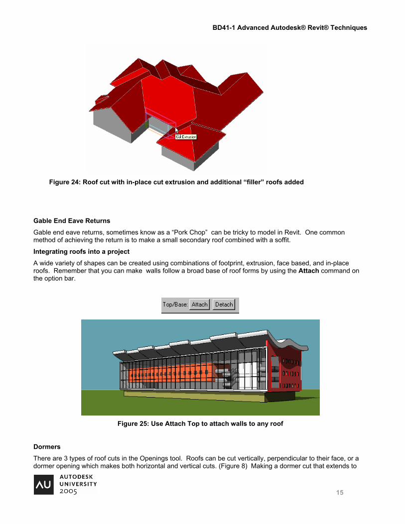
Figure 24: Roof cut with in-place cut extrusion and additional “filler” roofs added
Gable End Eave Returns
Gable end eave returns, sometimes know as a “Pork Chop” can be tricky to model in Revit. One common method of achieving the return is to make a small secondary roof combined with a soffit.
Integrating roofs into a project
A wide variety of shapes can be created using combinations of footprint, extrusion, face based, and in-place roofs. Remember that you can make walls follow a broad base of roof forms by using the Attach command on the option bar.
Figure 25: Use Attach Top to attach walls to any roof
Dormers
There are 3 types of roof cuts in the Openings tool. Roofs can be cut vertically, perpendicular to their face, or a dormer opening which makes both horizontal and vertical cuts. (Figure 8) Making a dormer cut that extends to
BD41-1 Advanced Autodesk® Revit® Techniques
16
the edge of a roof can be confusing. Dormer sketches that extend to the edge of a roof can be left as open loops as long as they extend to the edge of the roof.
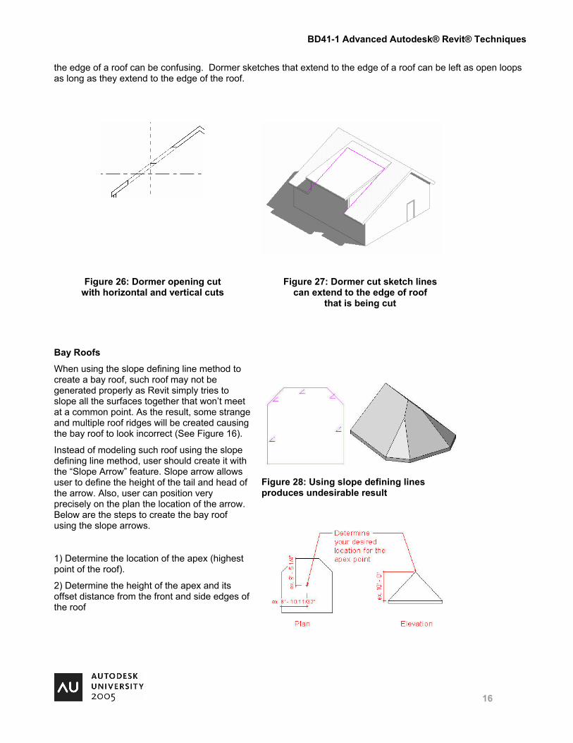
Figure 26: Dormer opening cut with horizontal and vertical cuts
Figure 27: Dormer cut sketch lines can extend to the edge of roof
that is being cut
Bay Roofs
When using the slope defining line method to create a bay roof, such roof may not be generated properly as Revit simply tries to slope all the surfaces together that won’t meet at a common point. As the result, some strange and multiple roof ridges will be created causing the bay roof to look incorrect (See Figure 16).
Instead of modeling such roof using the slope defining line method, user should create it with the “Slope Arrow” feature. Slope arrow allows user to define the height of the tail and head of the arrow. Also, user can position very precisely on the plan the location of the arrow. Below are the steps to create the bay roof using the slope arrows.
1) Determine the location of the apex (highest point of the roof).
2) Determine the height of the apex and its offset distance from the front and side edges of the roof
Figure 28: Using slope defining lines produces undesirable result
BD41-1 Advanced Autodesk® Revit® Techniques
17
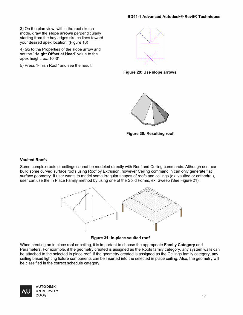
3) On the plan view, within the roof sketch mode, draw the slope arrows perpendicularly starting from the bay edges sketch lines toward your desired apex location. (Figure 16)
4) Go to the Properties of the slope arrow and set the “Height Offset at Head” value to the apex height, ex. 10’-0”
5) Press “Finish Roof” and see the result
Figure 29: Use slope arrows
Figure 30: Resulting roof
Vaulted Roofs
Some complex roofs or ceilings cannot be modeled directly with Roof and Ceiling commands. Although user can build some curved surface roofs using Roof by Extrusion, however Ceiling command in can only generate flat surface geometry. If user wants to model some irregular shapes of roofs and ceilings (ex. vaulted or cathedral), user can use the In Place Family method by using one of the Solid Forms, ex. Sweep (See Figure 21).
Figure 31: In-place vaulted roof
When creating an in place roof or ceiling, it is important to choose the appropriate Family Category and Parameters. For example, if the geometry created is assigned as the Roofs family category, any system walls can be attached to the selected in place roof. If the geometry created is assigned as the Ceilings family category, any ceiling based lighting fixture components can be inserted into the selected in place ceiling. Also, the geometry will be classified in the correct schedule category.
BD41-1 Advanced Autodesk® Revit® Techniques
18
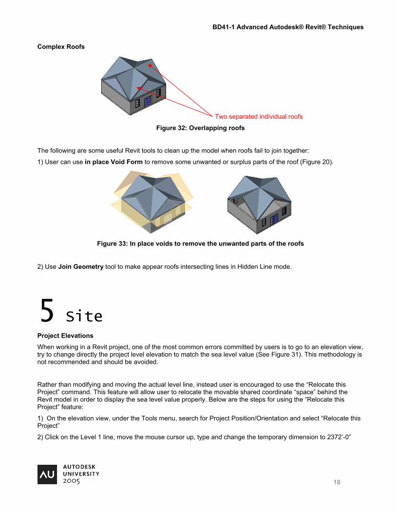
Complex Roofs
Two separated individual roofs
Figure 32: Overlapping roofs
The following are some useful Revit tools to clean up the model when roofs fail to join together:
1) User can use in place Void Form to remove some unwanted or surplus parts of the roof (Figure 20).
Figure 33: In place voids to remove the unwanted parts of the roofs
2) Use Join Geometry tool to make appear roofs intersecting lines in Hidden Line mode.
5 Site Project Elevations
When working in a Revit project, one of the most common errors committed by users is to go to an elevation view, try to change directly the project level elevation to match the sea level value (See Figure 31). This methodology is not recommended and should be avoided.
Rather than modifying and moving the actual level line, instead user is encouraged to use the “Relocate this Project” command. This feature will allow user to relocate the movable shared coordinate “space” behind the Revit model in order to display the sea level value properly. Below are the steps for using the “Relocate this Project” feature:
1) On the elevation view, under the Tools menu, search for Project Position/Orientation and select “Relocate this Project”
2) Click on the Level 1 line, move the mouse cursor up, type and change the temporary dimension to 2372’-0”
BD41-1 Advanced Autodesk® Revit® Techniques
19
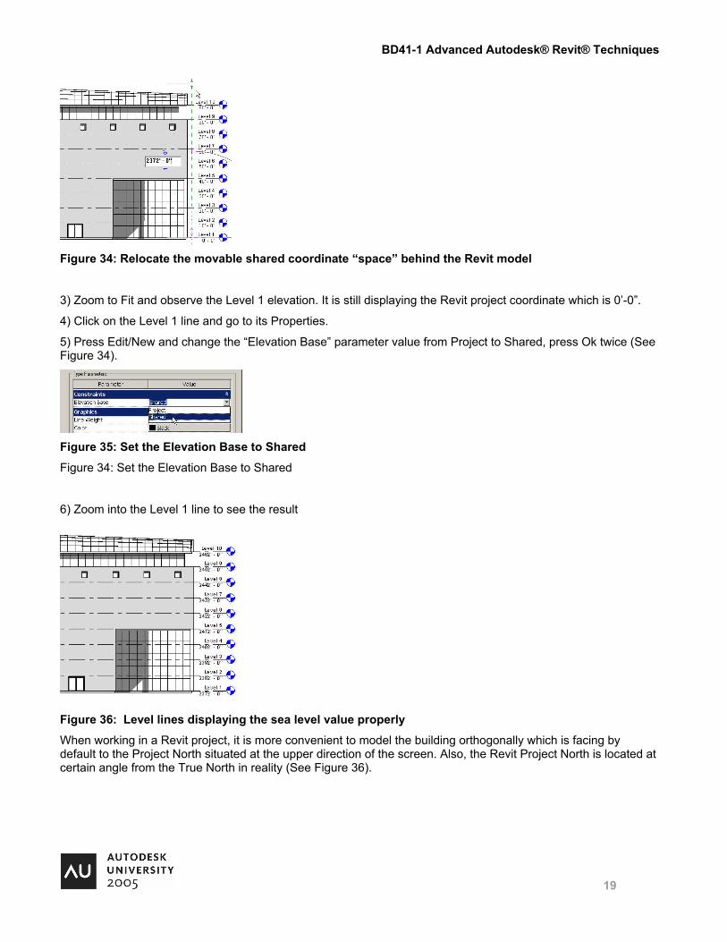
Figure 34: Relocate the movable shared coordinate “space” behind the Revit model
3) Zoom to Fit and observe the Level 1 elevation. It is still displaying the Revit project coordinate which is 0’-0”.
4) Click on the Level 1 line and go to its Properties.
5) Press Edit/New and change the “Elevation Base” parameter value from Project to Shared, press Ok twice (See Figure 34).
Figure 35: Set the Elevation Base to Shared
Figure 34: Set the Elevation Base to Shared
6) Zoom into the Level 1 line to see the result
Figure 36: Level lines displaying the sea level value properly
When working in a Revit project, it is more convenient to model the building orthogonally which is facing by default to the Project North situated at the upper direction of the screen. Also, the Revit Project North is located at certain angle from the True North in reality (See Figure 36).
BD41-1 Advanced Autodesk® Revit® Techniques
20
Orientation to True North
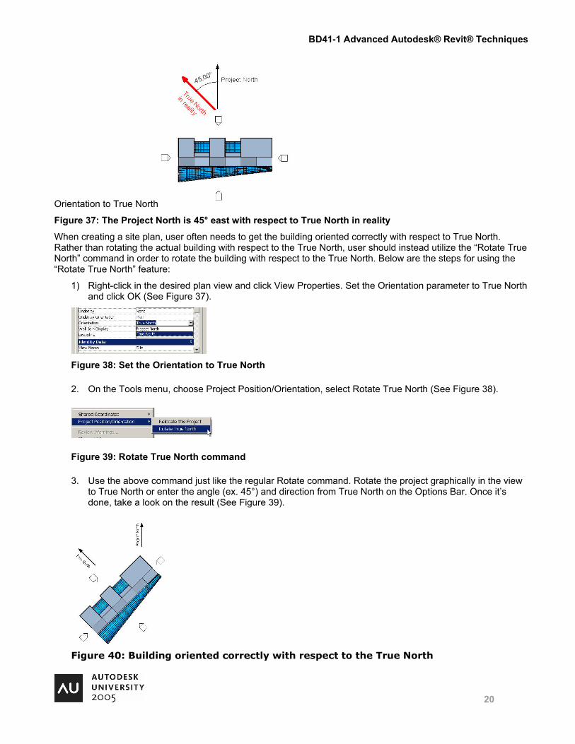
Figure 37: The Project North is 45° east with respect to True North in reality
When creating a site plan, user often needs to get the building oriented correctly with respect to True North. Rather than rotating the actual building with respect to the True North, user should instead utilize the “Rotate True North” command in order to rotate the building with respect to the True North. Below are the steps for using the “Rotate True North” feature:
1) Right-click in the desired plan view and click View Properties. Set the Orientation parameter to True North and click OK (See Figure 37).
Figure 38: Set the Orientation to True North
2. On the Tools menu, choose Project Position/Orientation, select Rotate True North (See Figure 38).
Figure 39: Rotate True North command
3. Use the above command just like the regular Rotate command. Rotate the project graphically in the view to True North or enter the angle (ex. 45°) and direction from True North on the Options Bar. Once it’s done, take a look on the result (See Figure 39).
Figure 40: Building oriented correctly with respect to the True North