Embed Size (px)
Citation preview
Advanced Diagnosis of High Voltage Power Cables
E. Gulski1*, P. Cichecki1, J.J. Smit1, P.P. Seitz 2, B. Quak2, F. Petzold3 and Frank de Vries 4 1Delft University of Technology, Mekelweg 4, 2628CD Delft, The Netherlands
2Seitz Instruments AG, Mellingerstrasse 12, CH-5443 Niederrohrdorf, Switzerland 3SebaKMT, Dr.-Herbert-Iannstr. 6, 96148 Baunach, Germany
4Nuon Tecno. Voltastraat 2, 1817 DD Alkmaar, The Netherlands *Email: [email protected]
Abstract: In this contribution based on field application of advanced diagnostics a systematic approach for condition assessment of high voltage (HV) power cables is discussed. Based on the assumption that there is not one dominant failure process in HV cable networks in addition to partial discharges also dielectric diagnosis has be included to determine the actual condition of service aged cable insulation systems.
1 GENERAL The transmission power cable networks (HV cable systems) are strategic assets and in contrast to medium voltage (MV) the HV networks are very reliable. In particular, failures in the HV network are not occurring as often as a result of the relative small number of components and the historical good quality and proper maintenance in the past of the network. Also, due to the high redundancy (ring networks, “N-1” criterion) and the possibility of remote switching actions from operation centres, the outage probability and time are relatively low [2]. Similar to other HV components e.g. power transformers, circuit breakers and overhead lines the average service age of transmission power cable networks is between 30-45 years [1]. Moreover, no or limited knowledge exists about such future performances as:
- insulation degradation processes, - operation reliability, - maintenance /replacement expectations.
It is known that the liberalization of the energy markets, the increase of power demand and higher flexibility towards high voltage grids, lead to a more severe exploitation of HV cable systems in the future. As a result, a system failure may lead in additio n to emergency repair costs also to a loss of income or to claims. According to [3] repair costs of a failure in a HV cable link can be estimated around 500 €/kV. This means that the repair of a failure in a 150kV link costs around 75 k€. In addition also costs of not delivered energy have to be taken in to account and these additional costs, depending on claims and penalties as contracted can be much higher. Thus, in coming years more and more strategic decisions have to be taken about maintenance or
replacement of the oldest or cables circuits [3,4], figure 1. Normally, such strategic decisions belong to the responsibilities of asset management (AM), [7]. In particular, based on information about the present and future asset performances e.g. technical condition and the knowledge of degradation processes, decisions about maintenance and replacement can be prepared. However, at present setting up such AM strategies may face three difficulties: a) due to very low number of failures no statistical
predictions are possible [5] , b) degradation processes of HV cables are more
complex and the systematic knowledge about the actual aging needs further investigations and field verifications as shown in [3], (figure 2a-b),
c) with regard to HV power cables no fixed diagnostics are available for on-site condition assessment [4,6,12,13], (figure 2c-d).
It follows that assessment of actual condition is getting more important [8 ,10]. Actual knowledge of the condition of HV cable systems may support the network managers
- to evaluate overall condition of the power network condition,
- to be able to estimate the reliability of the power network,
- to set up maintenance/replacement schedule, diagnostic data may provide important information for conditions assessment.
It is known, that HV power cable failure can occur as a result of the normally applied operational voltage or during a transient voltage lightning or switching surges.
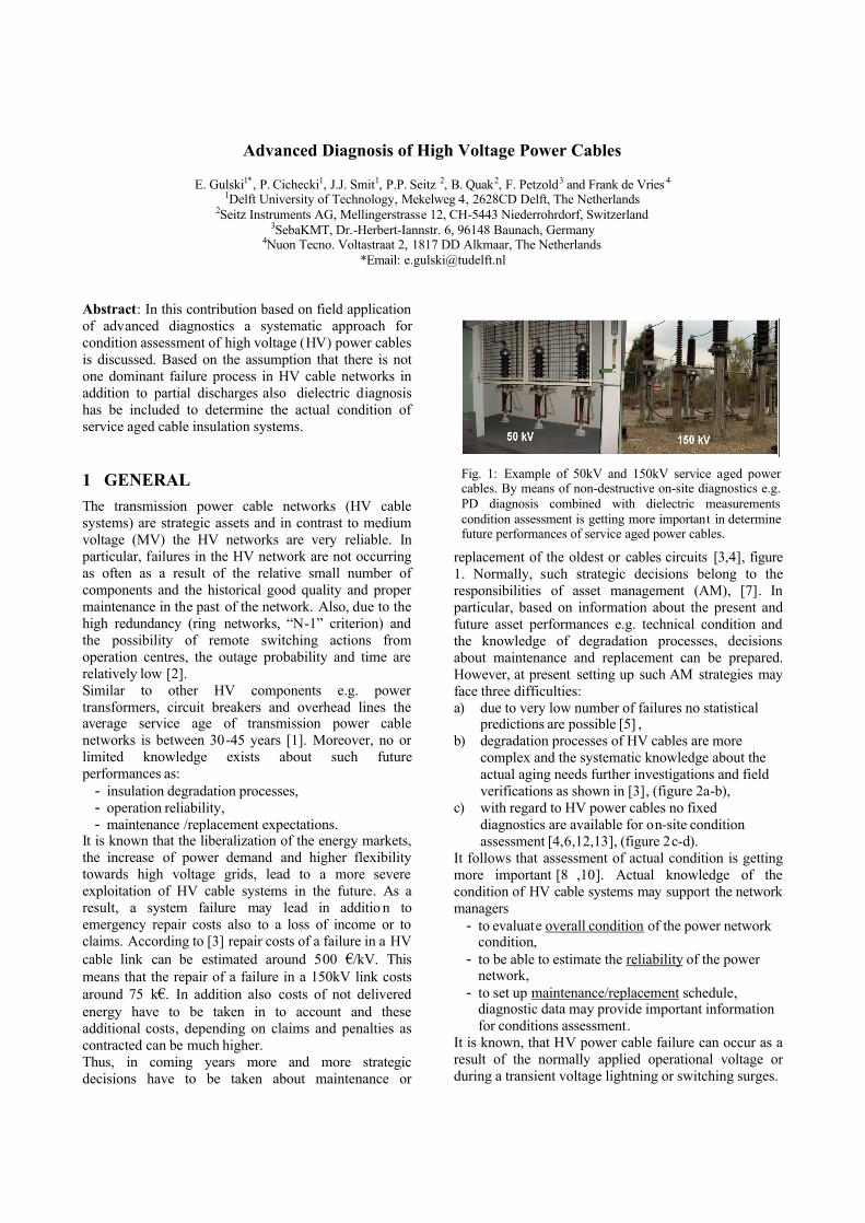
Fig. 1: Example of 50kV and 150kV service aged power cables. By means of non-destructive on-site diagnostics e.g. PD diagnosis combined with dielectric measurements condition assessment is getting more important in determine future performances of service aged power cables.
The failure can occur if localized electrical stresses are greater than the dielectric strength of dielectric materials in the area of the localized stress or the bulk dielectric material degrades to the point where it cannot withstand the applied voltage. Therefore performing non-destructive diagnostics on-site could be an important issue to determine the actual condition of the cable systems and to determine the future performances [9] . In particular there is need to develop programmes consisting of
- diagnostic tools, - implementation/application support, - knowledge rules,
to support the asset management of HV power cable circuits. Therefore in this contribution based on field application of advanced diagnostics a systematic approach for condition assessment of HV power cables is discussed.
2 HV INSULATION DIAGNOSTICS The insulation failures in a cable network may be caused by lower dielectric strength due to aging processes and by internal defects in the insulation system. It is known that unlike voltage testing, measurements of the dielectric may give an absolute indicator for the quality level of the cable insulation. For HV power cables different on-site inspections/diagnostics are available [1,3,12,13]. In particular with regard to information as provided, conclusions about short- and long-term condition can be made (figure 3). The results of these measurements may have a direct relation to the average qualitative level of the insulation at the moment of measurement and can thus be applied as a trend- or fingerprint measurement during future inspections. It follows from figure 3 that partial discharge diagnosis and dielectric diagnosis may play important role in short- and long-term condition assessment, figure 4 .
The partial discharge diagnosis may indicate weak spots in a cable connection. In order to run the measurement partial discharges are ignited in the cable insulation or joints by the application of a test voltage [10-12]. The occurrence of partial discharges have physical character and it is described by such important parameters as PD inception voltage, PD pulse magnitudes, PD patterns and PD site location in a power cable (figure 7). For utilities interested in applying PD diagnostics for condition assessment of its power cable networks al these parameters are of importance. In particular, analysing PD parameters for different types of cable insulation and cable accessories can result in developing experience norms [14]. Such norms
Oil-filled/ aged 40-60 years
Inst
alle
d le
ngth
num
ber o
f fai
lure
s
Oil-filled/aged 40 -60 years
Pipe type oil -filled/ aged 10 -50 years Pipe type oil -filled/ aged 10 -50 years
Inst
alle
d le
ngth
Num
ber o
f lea
kage
s
(a) (b)
(c) (d)
Oil-filled/ aged 40-60 years
Inst
alle
d le
ngth
num
ber o
f fai
lure
s
Oil-filled/aged 40 -60 years
num
ber o
f fai
lure
s
Oil-filled/aged 40 -60 years
Pipe type oil -filled/ aged 10 -50 years Pipe type oil -filled/ aged 10 -50 years
Inst
alle
d le
ngth
Num
ber o
f lea
kage
s
(a) (b)
(c) (d)
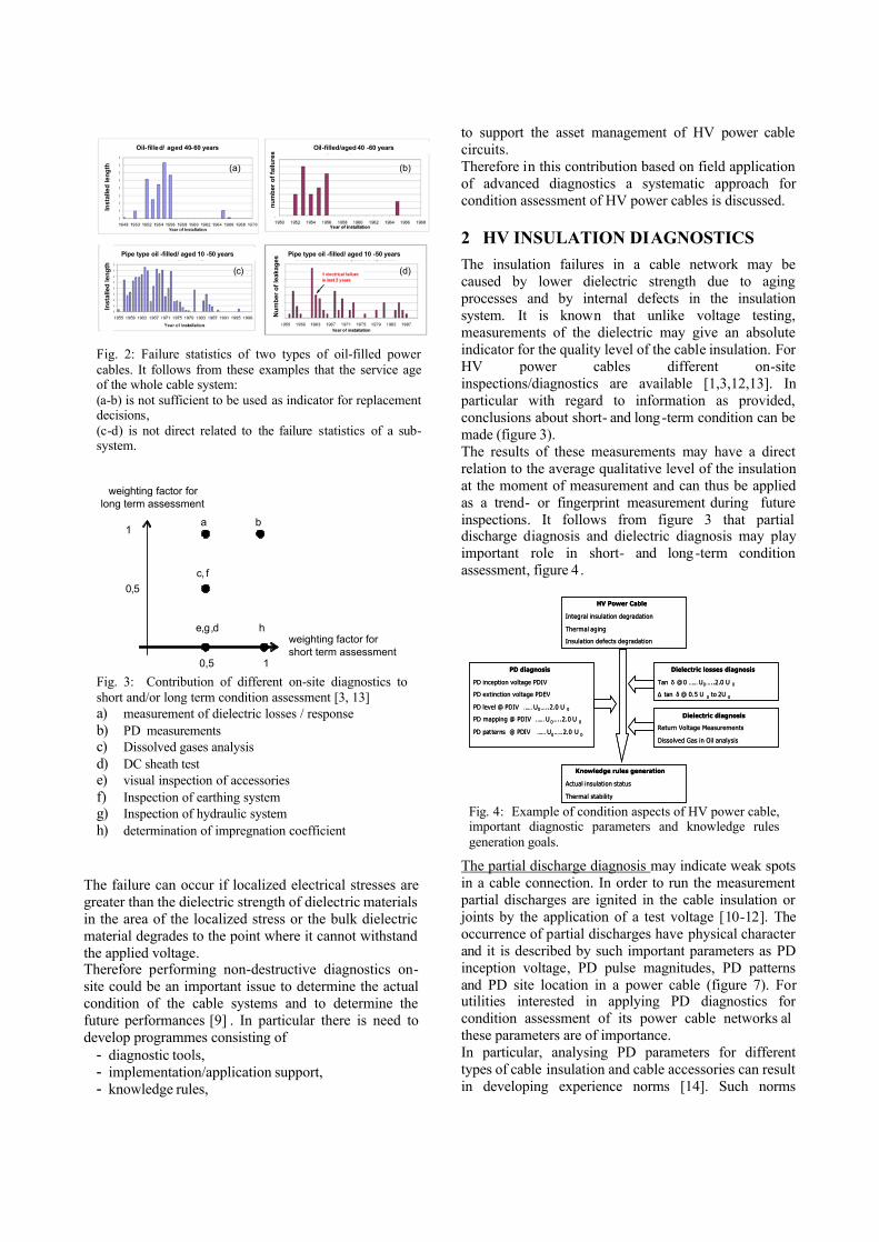
Fig. 2: Failure statistics of two types of oil-filled power cables. It follows from these examples that the service age of the whole cable system: (a-b) is not sufficient to be used as indicator for replacement decisions, (c-d) is not direct related to the failure statistics of a sub-system.
a
weighting factor for short term assessment
weighting factor for long term assessment
1
0,5
0,5 1
b
c, f
e,g,d h
Fig. 3: Contribution of different on-site diagnostics to short and/or long term condition assessment [3, 13] a) measurement of dielectric losses / response b) PD measurements c) Dissolved gases analysis d) DC sheath test e) visual inspection of accessories f) Inspection of earthing system g) Inspection of hydraulic system h) determination of impregnation coefficient
PD diagnosis
PD inception voltage PDIV
PD extinction voltage PDEV
PD level @ PDIV …… U0…..2.0 U 0
PD mapping @ PDIV …… U 0…..2.0 U 0
PD patterns @ PDIV …… U0…..2.0 U 0
Dielectric losses diagnosis
Tan δ @ 0 …… U0…..2.0 U 0
㥀 tan δ @ 0.5 U 0 to 2U 0
HV Power Cable
Integral insulation degradation
Thermal aging
Insulation defects degradation
Knowledge rules generation
Actual insulation status
Thermal stability
Dielectric diagnosis
Return Voltage Measurements
Dissolved Gas in Oil analysis
Fig. 4: Example of condition aspects of HV power cable, important diagnostic parameters and knowledge rules generation goals.
would very helpful in developing knowledge rules to support AM decisions. The tan δ measurement can be applied for the determination of the loss factor of the insulation material [ 3, 4]. This factor increases during the ageing process of the cable. The tan δ measurement should be regarded as a diagnostic and/or supporting measurement. In practice, in HV insulation is known that in addition to absolute value of tan δ at certain test voltage also the increment of tan delta as measured at two designated voltages so called 㥀 tan δ or tip-up is important for condition assessment. The loss tangent is measured as function of voltage to check the quality of impregnation. The tan δ value of a cable is strongly influenced by the composition of the connection, the trace, and the deviations in joints and the actual measurement is only applicable as trend measurement if composition circumstances of the trace and thermal conditions of successive measurements are virtually identical. For HV paper insulated cables the tan δ can be an important indicator of possible thermal breakdowns [4]. 3 ON-SITE DIAGNOSIS OF HV POWER CABLES For a complete on-site diagnosis of a power cables, it is necessary to energize the disconnected cable circuit using external voltage sources [9,17]. In particular, the detection equipment e.g. partial discharge or dielectric
loses can be directly connected to the cable conductors (or through the switchgear). In this way, the different phases of the cable circuit can be energized separately and the diagnostic tests can be performed. The capacitive power P needed to stress on-site the cable insulation is determined by the test frequency f, the cable capacitance Ccable and the test voltage Utest. In order to decrease the capacitive power demands for energizing cables as compared to 50Hz test voltages, different energizing methods using specific voltage shaped and frequencies have been introduced for PD diagnostics nowadays [9,15]. For this purpose, to perform on-site in non-destructive way advanced diagnosis of power cable circuits up to 250kV new method has been introduced [2,12]. One of the methods using damped AC voltages for detection and localization of PD in cables is known as Oscillating Wave Test System (OWTS), [11,12], see figure 5. For the generation of damped AC (DAC) voltages, the power demand is low due to the charging the cable capacitance with an continuously increasing DC voltage, after which the cable capacitance is switched in series with large inductance, resulting in an oscillating voltage wave with a frequency comparable to power frequencies. During charging period, due to stressing the cable section at continuously increasing DC voltage, directly followed by a switching process and period of several AC cycles no ‘‘steady state’’ DC conditions occur in the cable insulation [16]. The test frequency of the oscillating voltage wave is approximately the resonant frequency of the circuit.
Using damped AC voltages on-site PD diagnosis (detection, localization) and the measurement of dielectric losses at voltage AC frequencies between 20Hz and 500Hz have become possible. During seven years of worldwide application of this method wide range of experiences has been developed for power cables up to 36kV. Moreover, since 2004 this method is also applied for HV power cables up to 250kV [10,12,13]. Applying this method provides in addition to PD diagnostic information also the values of dielectric
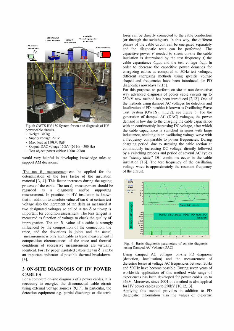
Fig. 5: OWTS HV 150 System for on-site diagnosis of HV power cable circuits. - Weight: 300kg - Supply voltage: 220V - Max. load at 150kV: 8µF - Output: DAC voltage 150kV (20 Hz - 500 Hz) - Test object: power cables: 100m -20km
Dam
ped
AC v
olta
ge
Partial discharges: PDIV, PD level, PD location
Dielectric losses
Dam
ped
AC v
olta
ge
Partial discharges: PDIV, PD level, PD location
Dielectric losses
Fig. 6: Basic diagnostic parameters of on-site diagnosis using Damped AC Voltage (DAC)
losses, see figure 6. Due to the fact that by using this method: - the frequency of damped AC voltages is in the range of
power frequency of acceptable HV test systems, - a number of power cycles is applied to the cable
sample provide ignition of PD sources in similar ways as compared to operating conditions,
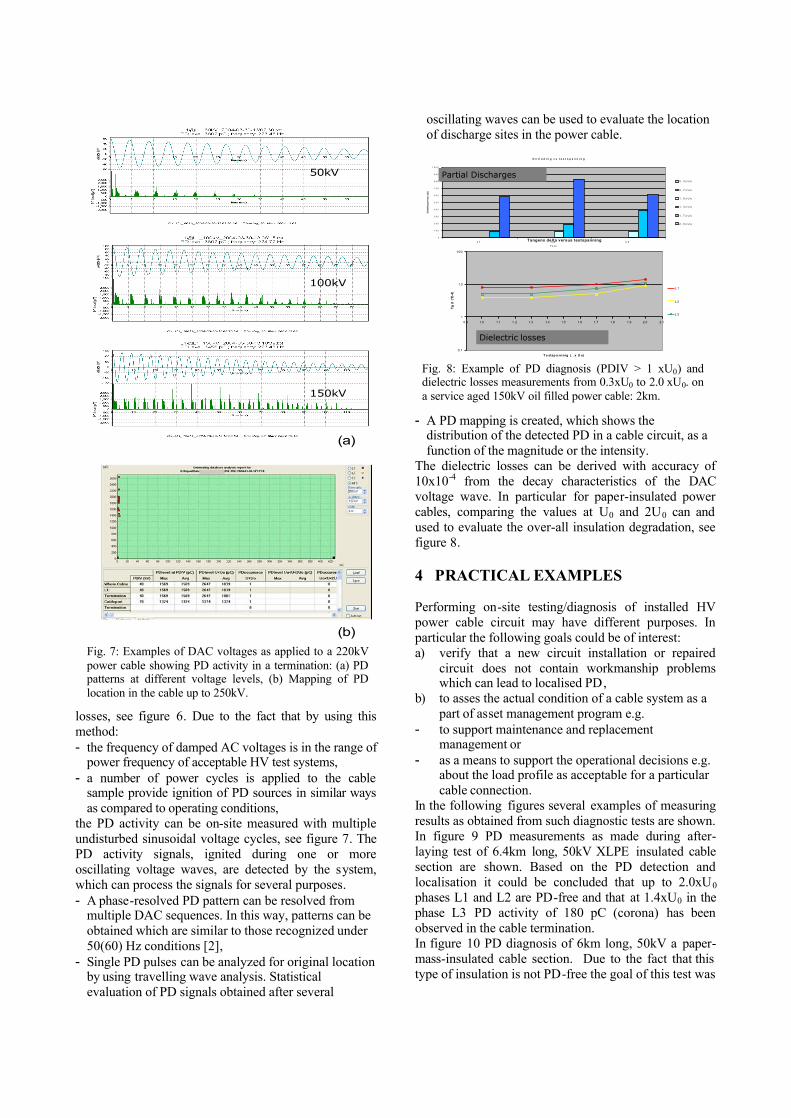
the PD activity can be on-site measured with multiple undisturbed sinusoidal voltage cycles, see figure 7. The PD activity signals, ignited during one or more oscillating voltage waves, are detected by the system, which can process the signals for several purposes. - A phase-resolved PD pattern can be resolved from
multiple DAC sequences. In this way, patterns can be obtained which are similar to those recognized under 50(60) Hz conditions [2],
- Single PD pulses can be analyzed for original location by using travelling wave analysis. Statistical evaluation of PD signals obtained after several
oscillating waves can be used to evaluate the location of discharge sites in the power cable.
- A PD mapping is created, which shows the distribution of the detected PD in a cable circuit, as a function of the magnitude or the intensity.
The dielectric losses can be derived with accuracy of 10x10-4 from the decay characteristics of the DAC voltage wave. In particular for paper-insulated power cables, comparing the values at U0 and 2U0 can and used to evaluate the over-all insulation degradation, see figure 8.
4 PRACTICAL EXAMPLES Performing on-site testing/diagnosis of installed HV power cable circuit may have different purposes. In particular the following goals could be of interest: a) verify that a new circuit installation or repaired
circuit does not contain workmanship problems which can lead to localised PD,
b) to asses the actual condition of a cable system as a part of asset management program e.g.
- to support maintenance and replacement management or
- as a means to support the operational decisions e.g. about the load profile as acceptable for a particular cable connection.
In the following figures several examples of measuring results as obtained from such diagnostic tests are shown. In figure 9 PD measurements as made during after-laying test of 6.4km long, 50kV XLPE insulated cable section are shown. Based on the PD detection and localisation it could be concluded that up to 2.0xU0 phases L1 and L2 are PD-free and that at 1.4xU0 in the phase L3 PD activity of 180 pC (corona) has been observed in the cable termination. In figure 10 PD diagnosis of 6km long, 50kV a paper-mass-insulated cable section. Due to the fact that this type of insulation is not PD-free the goal of this test was
50kV
100kV
150kV
(b)
(a)
50kV
100kV
150kV
(b)
(a)
Fig. 7: Examples of DAC voltages as applied to a 220kV power cable showing PD activity in a termination: (a) PD patterns at different voltage levels, (b) Mapping of PD location in the cable up to 250kV.
Tangens delta versus testspanning
0.1
1
1 0
100
0.9 1.0 1.1 1.2 1.3 1.4 1.5 1.6 1.7 1.8 1.9 2.0 2.1
T e stsp a nn ing (. . x U o)
Tg d
(*E
-4)
L 1
L 2
L 3
O n t l a d i n g v s t e s t s p a n n i n g
0
1 0 0
2 0 0
3 0 0
4 0 0
5 0 0
6 0 0
7 0 0
8 0 0
9 0 0
1 0 0 0
L 1 L 2 L 3F a s e
Ont
ladi
ngsn
ivea
u (p
C)
0 , 3 x U o
0 , 7 x U o
1 , 0 x U o
1 , 3 x U o
1 , 7 x U o
2 , 0 x U o
Partial Discharges
Dielectric losses
Fig. 8: Example of PD diagnosis (PDIV > 1 xU0) and dielectric losses measurements from 0.3xU0 to 2.0 xU0. on a service aged 150kV oil filled power cable: 2km.
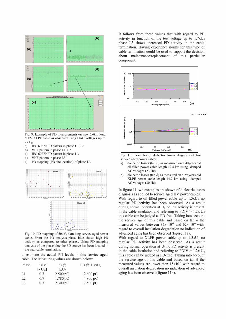
to estimate the actual PD levels in this service aged cable. The Measuring values are shown below:
It follows from these values that with regard to PD activity in function of the test voltage up to 1.7xU0 phase L3 shows increased PD activity in the cable termination. Having experience norms for this type of cable termination could be used to support the decision about maintenance/replacement of this particular component.
In figure 11 two examples are shown of dielectric losses diagnosis as applied to service aged HV power cables. With regard to oil-filled power cable up to 1.5xU 0 no regular PD activity has been observed. As a result during normal operation at U0 no PD activity is present in the cable insulation and referring to PDIV > 1.2x U0 this cable can be judged as PD-free. Taking into account the service age of this cable and based on tan 㭀 the measured values between 35x 10-4 and 62x 10 -4 with regard to overall insulation degradation no indication of advanced aging has been observed (figure 11a) . With regard to XLPE power cable up to 1.3xU0 no regular PD activity has been observed. As a result during normal operation at U0 no PD activity is present in the cable insulation and referring to PDIV > 1.2x U0 this cable can be judged as PD-free. Taking into account the service age of this cable and based on tan 㭀 the measured values are lower than 15x10-4 with regard to overall insulation degradation no indication of advanced aging has been observed (figure 11b).
Phase PDIV [x U 0]
PD @ 1xU0
PD @ 1.7xU0
L1 0.7 2.500 pC 2.600 pC L2 0.7 1.780 pC 4.800 pC L3 0.7 2.300 pC 7.500 pC
Phase L1 Phase L2
Phase L3
Phase L1 Phase L2
Phase L3
Fig. 10: PD mapping of 50kV, 6km long service aged power cable. From the PD analysis phase blue shows high PD activity as compared to other phases. Using PD mapping analysis of the phase blue the PD source has been located in the near cable termination.
(a)
(b)
(c)
(d)
(e)
(a)
(b)
(c)
(d)
(e)
Fig. 9: Example of PD measurements on new 6.4km long 50kV XLPE cable as observed using DAC voltages up to 2x U0: a) IEC 60270 PD pattern in phase L1, L2 b) VHF pattern in phase L1, L2 c) IEC 60270 PD pattern in phase L3 d) VHF pattern in phase L3 e) PD mapping (PD site location) of phase L3
R N C : A M K 6 6 K V to A D M I R A L T Y R D W E S T 2 3 0 k V
0,01
0,1
1
40 50 60 70Voltage [kV peak]
Die
lec
tric
Lo
ss
es
[%
]
L1L2L3
RNN: MANDAI MAIN 66kV to UPP THOMSON 66kV
0,1
1
10
40 50 60 70 75 80Voltage [kV peak]
Die
lec
tric
Lo
ss
es
[%
]
L1L2L3
(a)
(b)
R N C : A M K 6 6 K V to A D M I R A L T Y R D W E S T 2 3 0 k V
0,01
0,1
1
40 50 60 70Voltage [kV peak]
Die
lec
tric
Lo
ss
es
[%
]
L1L2L3
RNN: MANDAI MAIN 66kV to UPP THOMSON 66kV
0,1
1
10
40 50 60 70 75 80Voltage [kV peak]
Die
lec
tric
Lo
ss
es
[%
]
L1L2L3
(a)
(b)
Fig. 11: Examples of dielectric losses diagnosis of two service aged power cables: a) dielectric losses (tan ∂) as measured on a 40years old
oil filled power cable length 12.4 km using damped AC voltages (23 Hz)
b) dielectric losses (tan ∂) as measured on a 29 years old XLPE power cable length 14.9 km using damped AC voltages (30 Hz)
5 CONDITION EVALATION AND KNOWLEDGE RULES As shown in previous paragraphs performing on-site diagnostics can provide valuable information about the actual insulation degradation e.g. by the presence of insulation weak-spots (partial discharges) and increase of dielectric losses of the insulation, see figure 4. As a result to support the maintenance and replacement decision process these diagnostic data have to be transformed into condition categories [8]:
Condition Definition Normal - No maintenance necessary
- No problems Degradation initiation
- Short term: No impact on network reliability
- Long term: without any maintenance possible life time reduction
Degradation in progress
- Short term: cable can still be operated but the network reliability is decreased Maintenance is necessary
Failure - Cable can not be operated and maintenance is necessary
- Based on economics repair or replacement
According to [14] using statistical analyses of diagnostic data of particular types of cable insulation and cable accessories it should be possible to develop decision boundaries. 6 CONCLUSIONS Based on the research results as discussed in this contribution the following can be concluded: 1. New and service aged HV power cables are
important assets and have to be tested on-site; 2. PD and dielectric losses diagnosis at Damped AC
voltages can be used for non-destructive on-site testing of new and service aged power cables;
3. Based on field experiences and using diagnostic data (PD, dielectric losses) for different types of insulation and accessories experience norms can be estimated;
4. Such experience norms for PD and dielectric losses can be used to support the Asset Management decision processes of HV power cable networks;
7 REFERENCES [1] Cigre WG 37-27, Aging of the System - Impact on
Planning, Cigre Brochure 2001 [2] F.J. Wester, Condition Assessment of Power Cables
Using PD Diagnosis at Damped AC Voltages, ISBN 90-8559-019-1, 2004
[3] Popma J. and Pellis J., Diagnostics for high voltage cable systems, proceedings ERA conference on HV plant life extension, Belgium, 23-24 November, 2000
[4] Harrewijn R., Doeland W. van, Weerd P. van de, On-site tan delta measurements as function of the temperature on a 150 kV gas pressurized cable system, proceedings ERA conference on HV plant life extension, Belgium, 23-24 November, 2000
[5] R.A. Jongen, P. H. F. Morshuis, E. Gulski, J.J. Smit, J. Maksymiuk, A.L.J. Janssen, Application of Statistical Methods for Making Maintenance Decisions within Power Utilities, IEEE Electrical Insulation Magazine Nov/Dec 2006, Vol. 22, No 6
[6] E. Gulski, F.J. Wester, W. Boone, N. van Schaik, E.F. Steennis, E.R.S. Groot, J. Pellis, B.J. Grotenhuis, Knowledge Rules Support for CBM of Power Cable Circuits, CIGRE 2002 Session, paper 104
[7] E. Gulski, J.J. Smit, B. Quak, E.R.S. Groot, F. Petzold, Asset management of power cables systems, proceedings CIRED MNC Asia Pacific Conference on T&D Asset Management 21-23 November, 2006 Petaling Jaya Malaysia
[8] E. Gulski, B. Quak, E.R.S. Groot, Th Strehl, E. Lemke, et al, Fundamental Aspects of Data Quality for HV Asset Condition Assessment, Cigre ELECTRA No 228 October 2006
[9] CIGRE WG 21.05, Diagnostic Methods for HV Paper Cables and Accessories, Electra No. 176, February 1998
[10] E. Gulski, S. Meijer, J.J. Smit, F. de Freis, H. Geene, E.R.S. Groot, M. Boone, A. Bun, Condition assessment and AM decision support for transmission network components, Proceedings CIGRE 2006, Session, paper D1-109
[11] E. Gulski, F.J. Wester, J.J. Smit, P.N. Seitz and M. Turner, Advanced PD diagnostic of MV power cable system using oscillating wave test system, IEEE Electrical Insulation Magazine, 16, 2, 2000, p. 17-25
[12] E. Gulski, F.J. Wester, J.J. Smit, E.R.S. Groot, Ph. Wester, P.N. Seitz, Transmission Power Cables PD Detection at Damped AC Voltages, Jicable 2003
[13] E. Gulski, E, F.J. Wester, Ph. Wester, E.R.S. Groot, J.W. van Doeland, Condition assessment of high voltage power cables. Proceedings CIGRE 2004 Session, paper D1-103
[14] E. Gulski, O.M. Piepers, J.J. Smit, F. de Vries, Statistical Analysis of Diagnostic Data of HV Components, XVth International Symposium on HV, Ljubljana, 2007, paper 90
[15] E. Gulski, E. Lemke, M. Gamlin, E. Gockenbach, W. Hauschild, E. Pultrum, Experiences in partial discharge detection of distribution power cable systems. Electra, 34-43.
[16] F.H. Kreuger, Industrial High DC Voltage, Delft University Press, 1995
[17] W. Hauschild, W. Schufft, R. Plath, K. Polster, The Technique of AC On-Site Testing of HV Cables by Frequency-Tuned Resonant Test Systems, CIGRE 2002, paper 33-304.