Embed Size (px)
Citation preview
105
BULGARIAN ACADEMY OF SCIENCES
CYBERNETICS AND INFORMATION TECHNOLOGIES Volume 20, No 2 Sofia 2020 Print ISSN: 1311-9702; Online ISSN: 1314-4081
DOI: 10.2478/cait-2020-0020
Advanced Embedded Control of Electrohydraulic Power Steering System
Tsonyo Slavov1, Alexander Mitov2, Jordan Kralev1 1Technical University of Sofia, Department Systems & Control, 1000 Sofia, Kl. Ohridski Blvd, Bulgaria 2Technical University of Sofia, Department. Hydroaerodynamics & Hydraulic Machines, 1000 Sofia, Kl. Ohridski Blvd, Bulgaria E-mails: [email protected] [email protected] [email protected]
Abstract: The article presents a developed embedded system for control of electrohydraulic power steering based on multivariable uncertain plant model and advanced control techniques. The plant model is obtained by identification procedure via “black box” system identification and takes into account the deviations of the parameters that characterize the way that the control signal acts on the state of the model. Three types of controller are designed: Linear-Quadratic Gaussian (LQG) controller, H∞ controller and μ-controller. The main result is a performed comparative analysis of time and frequency domain properties of control systems. The results show the better performance of systems based on µ-controllers. Also the robust stability and robust performance are investigated. All three systems achieved robust stability which guarantees their workability, but only the system with µ-controller has robust performance against prescribed uncertainties. The control algorithms are implemented in specialized 32-bit microcontroller. A number of real world experiments have been executed, which confirm the quality of the electrohydraulic power steering control system. Keywords: Linear-Quadratic Gaussian (LQG) controller, Kalman filter, H∞ controller, μ-controller, electrohydraulic steering system, embedded control.
1. Introduction
Globally, in recent years, the concept of mobile machines has integrated the notion of motor vehicles moving most often off public roads. Unlike the other vehicles, except for the transport of persons and goods, they are most often used for special purposes. An example of such mobile machines are road construction, material handling, agricultural and other factory transport vehicles. The main drive system in them is a hydraulic fluid power system, which is used not only for movement and working functions but also for control оf their steering direction. Steering system of these machines is subject to the hydrostatic principle. The mobile machines steering system does not have a mechanical feedback from steering axle to the steering wheel, unlike automotive steering [1]. In this aspect, the steering force is transmitted by hydraulic energy based on working fluid. However such kind of steering systems are
106
applicable only to mobile machines traveling at speeds not exceeding 60 km/h [2]. The most important unit in this system is the Hydrostatic Steering Unit (HSU) which has been studied intensively by several authors. Their results highlight some disadvantages of such hydraulic devices:
Series connection in HSU between gear wheel set (G-rotor) and rotary (spool/sleeve) valve forces constant steering ratio from steering wheel to the servo cylinder when working in normal or in emergency (without hydraulic power supply) mode of operation. Hence steering wheel is stiffer to human operator commands in emergency mode. This difficulty arises from geometric constraints ‒ displacement volume, cylinder active surface, bulk volume enclosed in the pipelines for connecting the HSU to the steering cylinder [2].
HSU can initiate fluid flow rate only after a small angular movement of the steering wheel as consequence of positive overlap in the rotary valve.
An increase of internal leakages would lead to undesirable drifts in the steering wheel and in the vehicle movement direction.
Introducing the proportional electrical control module of HSU provides opportunity to overcome the above mentioned disadvantages. This leads to significant practical and scientific interest in studying of ElectroHydraulic Steering Unit (EHSU). The workability and accuracy of EHSU mainly depends on embedded control system. From control point of view the EHSU is nonlinear multivariable complex plant which operates in presence of significant disturbances [3]. For example the exact loading torques acting upon steering axle remain unknown except if not continuously monitored. Moreover the hydraulic devices are designed with respect to maximizing efficient energy utilization some constructive elements are characterized with nonlinearities [4]. The uncertainty caused by such elements can impair closed-loop stability and performance [5]. Embedded control algorithms have to be carefully examined with respect to uncertainties before deployment into actual machine [6]. The known embedded system for control of EHSU is based mainly on PID controller and its modifications [7, 8]. The general advantages of PID controller are that they can be tuned with simple methods based on the simple plant model. It is well known that the PID controller cannot ensure the control performance in case of multivariable nonlinear plant model and in presence of significant disturbance [9, 10]. Moreover it cannot guarantee robust stability and robust performance of control system against plant parameters uncertainties [11]. This uncertainties arise in linear models when the plant operates in wide working range, which is the case in the presented study. For such cases the control theory suggests various advance control laws as Linear Quadratic Gaussian (LQG), H∞ and µ which can provide control system performance [12, 13]. However for design of these advanced controllers a linear multivariable plant model is required. Development of sufficiently accurate model based on the physical laws requires a lot of apriori information for many construction elements such as hydraulic resistance, volumes, valves spring constant etc. In real world this information is insufficient, inexact or fully absent. The powerful approach for development of a linear multivariable plant model, which does not require detailed a priory information, is the so called “black box” system identification [14, 15].
107
The lack of EHSU based on multivariable controllers motivates the authors to develop and investigate an embedded system for control of EHSU with advanced control techniques. Previous studies of the authors in the design of LQG, H and μ-controllers for control of EHSU are presented in [16, 17, 18]. In this study for the first time the whole process of development of embedded system for control of EHSU based on advanced control techniques is given. This process includes development of hardware setup, estimation of useful for control purpose uncertain plant model, synthesis of various control laws, and development of control software and its implementation into appropriate microcontroller and finally investigation of closed-loop system performance. The results obtained by detailed comparison of frequency and time domain properties of designed control systems are shown for the first time too. Also the new study of the robust performance of control systems based on the LQG, H and μ-controllers is performed. This analysis is assessed by calculation of bounds for the structured singular value μ. The real behaviour of the system designed is compared on the basis of real world experiments.
The paper is organized as follows: Section 2 presents developed hardware layout of the control system and estimated nominal and uncertain models of electrohydraulic power steering system, Section 3 shortly shows design of LQG, H∞ and μ-controllers, Section 4 gives the comparison between control systems, Section 5 presents control laws implementation and in Section 6 experimental results are given.
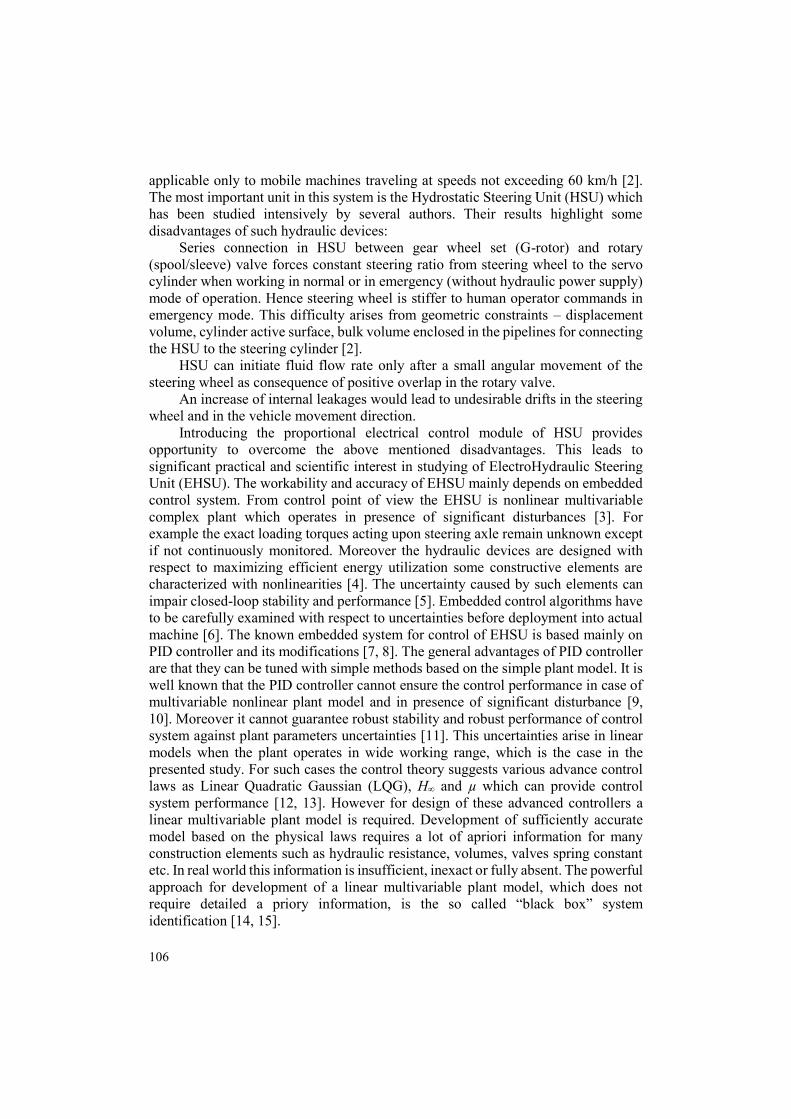
2. Hardware layout
Fig. 1. Hydraulic schematic of EHSU test-bench
108
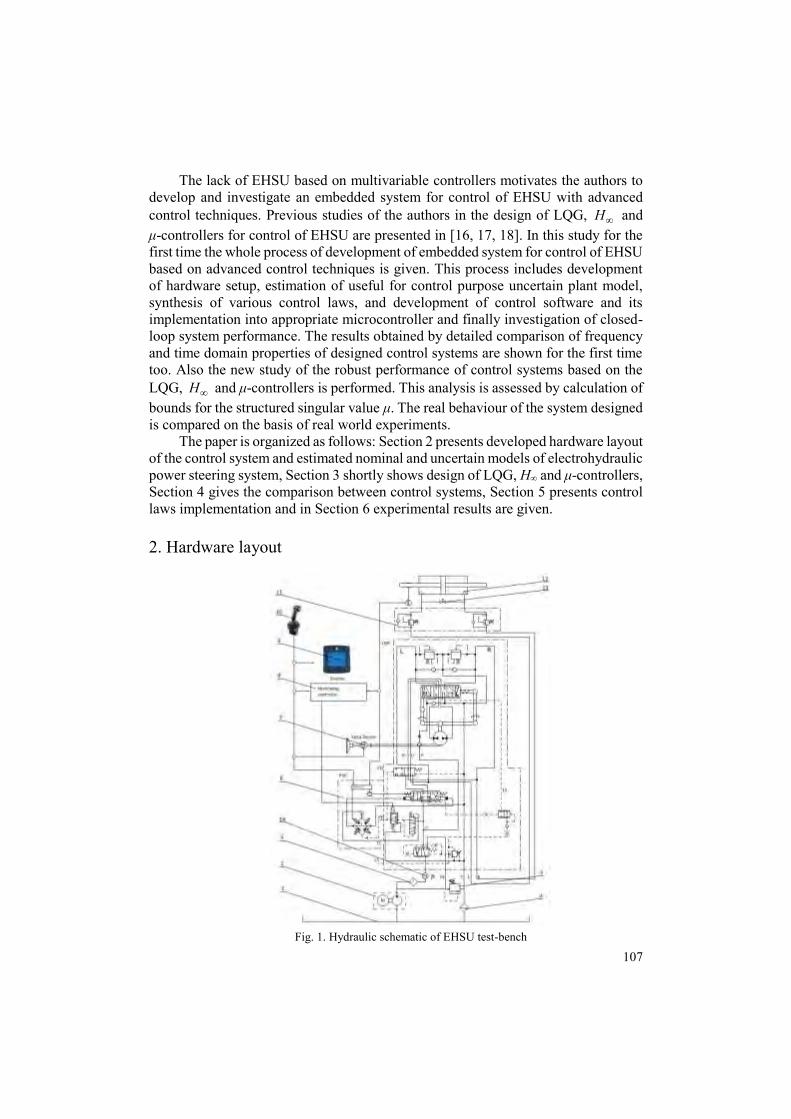
Authors have designed and implemented a laboratory hydraulic test bench for studying EHSU type OSPEC200 LSRM, according technical data sheet from the manufacturer [19]. Fig. 1 shows designed hydraulic schematic of the test bench system, presented in detail in [20]. The real implementation of laboratory test bench is shown in Fig. 2.
Fig. 2. Photo of the laboratory test-bench with its main functional components
Digital control system configuration is composed of MC012-22 microcontroller [21], joystick JS6000, EHSU OSPEC200LSRM with integrated PVE module, steering servo cylinder (80/50/300 mm), and piston position feedback resistive sensor. All programmable components are interconnected through CAN network. For software development, program loading and data acquisition is used a desktop PC with installed PLUS+1 Guide IDE. MC012 controller being CE compliant is suited for use in distributed machine control system. Its architecture is based on Digital Signal Processor (DSP) TMS320F2812 from Texas Instruments (TI) providing 150 MHz processing speed, 128K internal flash, multifunction input and 32-bit fixed-point arithmetic. Its input ports can measure analogue voltage, frequency and resistance. Its output ports can generate PWM signals.
A PVE module (position 6, Fig. 1) is an electrohydraulic pilot stage of main proportional spool valve (EH), which determinate the flow rate and thus control the piston movement of steering cylinder (position 12, Fig. 1). This piston position is transformed to variable voltage through precise resistive element after which it is fed to an ADC input of the microcontroller. In the microcontroller there is a program loaded to control cylinder piston position. A PVE module composed of four (2-way 2-position) micro valves connected in full-bridge scenario. This configuration transforms the electrical signal from the microcontroller to hydraulic one which is amplified to drive a proportional spool valve.
The designed controllers requires a linear state-space model of the plant. To obtain such model the identification experiment is performed. The details on identification experiment can be found in [16]. The input-output data is collected with sample time of 0 0.05T s. The aim of identification is to estimate the state space model
(1) ( 1) ( ) ( ) ( ),
( ) ( ) ( ),x k Ax k Bu k K k
y k Cx k k
where T
1 2( ) ... nx k x x x is a state vector, ( ) 5000 5000u k is the control
action (signal applied to the control input of PVE), T
pres pos( )y k y y is the output
109
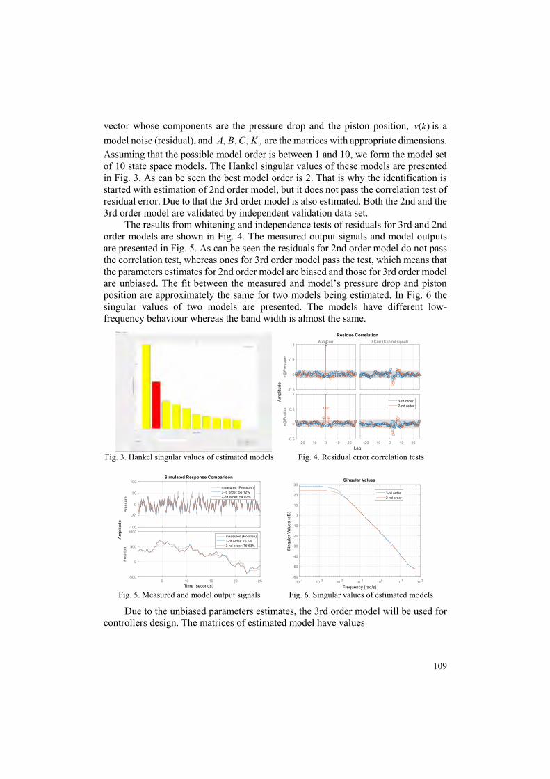
vector whose components are the pressure drop and the piston position, ( )v k is a model noise (residual), and , , , vA B C K are the matrices with appropriate dimensions. Assuming that the possible model order is between 1 and 10, we form the model set of 10 state space models. The Hankel singular values of these models are presented in Fig. 3. As can be seen the best model order is 2. That is why the identification is started with estimation of 2nd order model, but it does not pass the correlation test of residual error. Due to that the 3rd order model is also estimated. Both the 2nd and the 3rd order model are validated by independent validation data set.
The results from whitening and independence tests of residuals for 3rd and 2nd order models are shown in Fig. 4. The measured output signals and model outputs are presented in Fig. 5. As can be seen the residuals for 2nd order model do not pass the correlation test, whereas ones for 3rd order model pass the test, which means that the parameters estimates for 2nd order model are biased and those for 3rd order model are unbiased. The fit between the measured and model’s pressure drop and piston position are approximately the same for two models being estimated. In Fig. 6 the singular values of two models are presented. The models have different low-frequency behaviour whereas the band width is almost the same.
Fig. 3. Hankel singular values of estimated models Fig. 4. Residual error correlation tests
Fig. 5. Measured and model output signals Fig. 6. Singular values of estimated models
Due to the unbiased parameters estimates, the 3rd order model will be used for controllers design. The matrices of estimated model have values
110
(2)
0.8769 0.3987 0.3986 0.00430 0 1 , 0.0011 ,
0.1666 0.5099 1.509 0.00210.1112 0.06214
1 0 0, 0.09525 1.55 .
0 1 00.2003 1.897
v
A B
C K
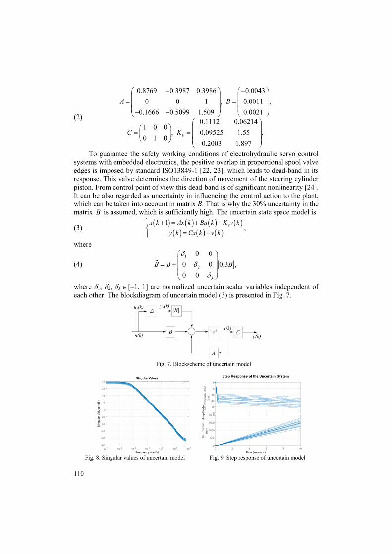
To guarantee the safety working conditions of electrohydraulic servo control systems with embedded electronics, the positive overlap in proportional spool valve edges is imposed by standard ISO13849-1 [22, 23], which leads to dead-band in its response. This valve determines the direction of movement of the steering cylinder piston. From control point of view this dead-band is of significant nonlinearity [24]. It can be also regarded as uncertainty in influencing the control action to the plant, which can be taken into account in matrix B. That is why the 30% uncertainty in the matrix B is assumed, which is sufficiently high. The uncertain state space model is
(3) ,
where
(4) 1
2
3
0 00 0 0.3 ,0 0
B B B
where 1, 2, 3 [–1, 1] are normalized uncertain scalar variables independent of each other. The blockdiagram of uncertain model (3) is presented in Fig. 7.
Fig. 7. Blockscheme of uncertain model
Fig. 8. Singular values of uncertain model Fig. 9. Step response of uncertain model
1 vx k Ax k Bu k K v ky k Cx k v k
111
The set of plant singular values and the transient responses in pressure drop, and in position of the uncertain model for a various admissible values of uncertain parameters is presented in Fig. 8 and Fig. 9. As can be seen from both figures, the uncertainty leads to a variation in the static gain of the plant.
3. Controllers design
The estimated 3rd order nominal model is used to design of LQG and H∞ controllers, whereas the 3rd order uncertain model is utilized in µ-controller design. The detailed results corresponding to design of LQG, H∞ controllers for electrohydraulic steering control is presented in [16, 17]. In this study the main aim is to investigate and to compare the performance of control system based on the controllers developed. For this reason only a short description of controller design procedure is presented. Further for the sake of brevity the control systems based on LQG, H∞ and µ-controllers will be called “LQG system”, “H∞ system” and “µ-system”.
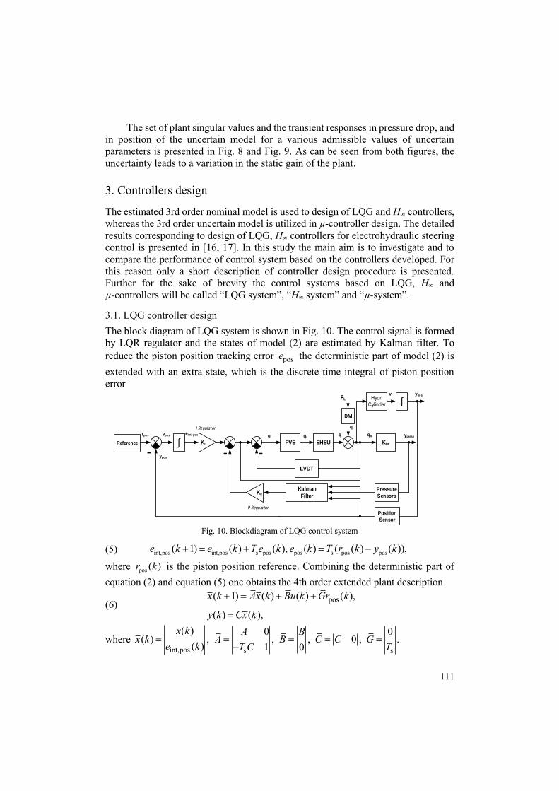
3.1. LQG controller design The block diagram of LQG system is shown in Fig. 10. The control signal is formed by LQR regulator and the states of model (2) are estimated by Kalman filter. To reduce the piston position tracking error pose the deterministic part of model (2) is extended with an extra state, which is the discrete time integral of piston position error
Reference EHSU
DM
Kc
Position
Sensor
rpos u
I Regulator
v
-PVE Khc
ʃ Hydr.Cylinder
LVDT
Kalman
Filter
ypos
ypos
ypress
FL
P Regulator
qs
-
qepos
ql
qd
Pressure
Sensors
KIʃ eint, pos
-
Fig. 10. Blockdiagram of LQG control system
(5) int,pos int,pos s pos pos s pos pos( 1) ( ) ( ), ( ) ( ( ) ( )),e k e k T e k e k T r k y k where pos ( )r k is the piston position reference. Combining the deterministic part of equation (2) and equation (5) one obtains the 4th order extended plant description
(6) pos( 1) ( ) ( ) ( ),
( ) ( ),
x k Ax k Bu k Gr k
y k Cx k
where int,pos s s
( ) 0 0( ) , , , 0 , .
( ) 1 0x k A B
x k A B C C Ge k T C T
112
The control action is formed by the equation (7) c( ) ( ), [ ],iu k Kx k K K K where Kc is the state feedback controller matrix and Ki is the integral part of controller. The LQR controller is obtained from minimization of performance criteria [6, 13]
(8) T T
0( ) ( ) ( ) ( ) ( )
kJ u x k Qx k u k Ru k
,
where 4
4
4
7 10 0 0 0
0 10 0 0
0 0 10 00 0 0 0
Q
and 5000R .
Since the state x(k) of is not measured, the optimal control law (7) is evaluated as (9) c int,posˆ( ) ( ) ( )iu k K x k K e k , where ˆ( )x k is the estimate of x(k). It is obtained by Kalman filter (10) ˆ ˆ ˆ( 1) ( ) ( ) ( ( 1) ( ) ( ))fx k Ax k Bu k K y k CBu k CAx k .
The variance 108.97 0
0 27.44vD
of model noise ( )v k is used in Kalman
filter design.
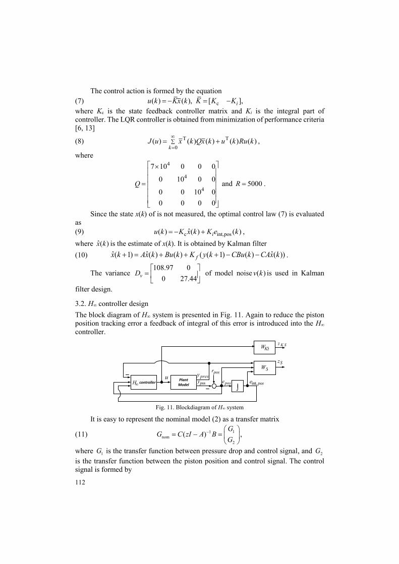
3.2. H∞ controller design The block diagram of H∞ system is presented in Fig. 11. Again to reduce the piston position tracking error a feedback of integral of this error is introduced into the H∞ controller.
u Plant Model
controllerH
posr SW
KSW
Sz
posypresy
pose int, pose
K Sz
Fig. 11. Blockdiagram of H∞ system
It is easy to represent the nominal model (2) as a transfer matrix
(11) 11nom
2
( )G
G C zI A BG
,
where 1G is the transfer function between pressure drop and control signal, and 2Gis the transfer function between the piston position and control signal. The control signal is formed by
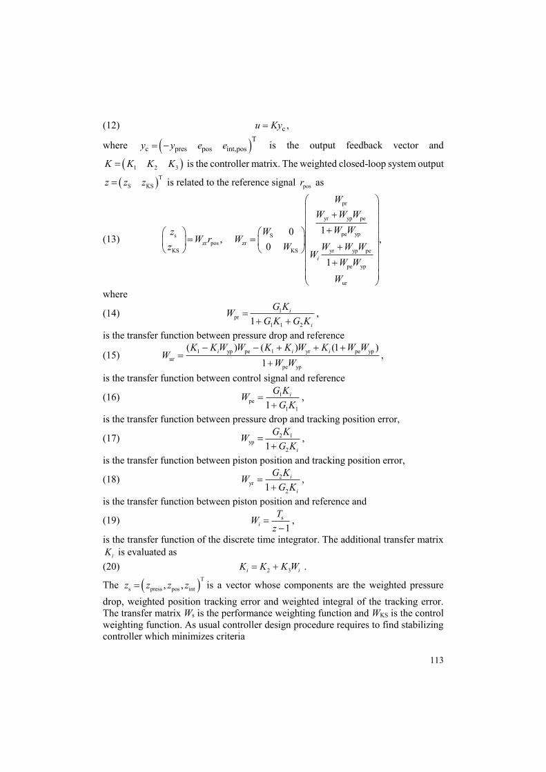
113
(12) c ,u Ky
where T
c pres pos int,posy y e e is the output feedback vector and
1 2 3K K K K is the controller matrix. The weighted closed-loop system output
T
S KSz z z is related to the reference signal posr as
(13)
pr
yr yp pe
pe yps Szr pos zr
KS KS yr yp pe
pe yp
ur
10, ,
01i
WW W W
W Wz WW r W
z W W W WW
W WW
where
(14) 1pr
1 1 21i
i
G KWG K G K
,
is the transfer function between pressure drop and reference
(15) 1 yp pe 1 yr pe ypur
pe yp
( ) ( ) (1 )1
i i iK K W W K K W K W WW
W W
,
is the transfer function between control signal and reference
(16) 1pe
1 11iG KW
G K
,
is the transfer function between pressure drop and tracking position error,
(17) 2 1yp
21 i
G KWG K
,
is the transfer function between piston position and tracking position error,
(18) 2yr
21i
i
G KWG K
,
is the transfer function between piston position and reference and
(19) s
1iTW
z
,
is the transfer function of the discrete time integrator. The additional transfer matrix iK is evaluated as
(20) 2 3i iK K K W .
The T
s press pos int, ,z z z z is a vector whose components are the weighted pressure drop, weighted position tracking error and weighted integral of the tracking error. The transfer matrix Ws is the performance weighting function and WKS is the control weighting function. As usual controller design procedure requires to find stabilizing controller which minimizes criteria
114
(21) stibilizing
zrminK
W
.
In practice the design procedure finds the suboptimal H∞ controller which provides (22) zrW
,
where is a positive scalar. If obtained value of is smaller than 1, then the design performance criteria is satisfied. The controller design is performed for various weight functions. On the basis of simulation results the weightfunctions are chosen as
(23) s KS0.8(0.1 1)diag 0.1 0.005 , 0.08
0.5 1sW Z W
s
.
The obtained value of is 0.6899.
3.3. µ-controller design The aim of the -controller is to ensure robust performance of steering cylinder position in presence of plant uncertainty. As noted above the model uncertainty represents static nonlinearity in electrohydraulic steering plant. The block diagram of -system is the same as the one presented in Fig. 11, if the block named “H∞-controller” is replaced by block named “-controller” and if the uncertain plant model is used instead nominal one. The unc ( )G is the uncertain transfer matrix corresponding to uncertain state space model (4)
(24) unc,11unc
unc,2
( ) ( )G
G C zI A BG
.
If the controller transfer functions is represented as these in Equation (11), the weighted closed-loop system output z are related to the reference signal rpos as
(25)
pr
yr yp pe
pe yps szr pos zr
KS KS yr yp pe
pe yp
ur
10, ,
0
1i
WW W W
W Wz WW r W
z W W W WW
W WW
where the transfer functions prW , urW , peW , ypW and yrW are the same as these in equations (14)-(20) if transfer functions 1G and 2G are replaced with umc,1G and
umc,2G , respectively. The performance criterion used in -synthesis requires the transfer matrix in
(25) from the exogenous input signal posr to the weighted output signal z to be small
in sense of (H-infinity norm), for all possible uncertain plant models unc ( )G . This requirement ensures small signals in output feedback vector
115
T
c pres pos int,posy y e e and small control action u . The performance weighting filters are selected to guarantee required tracking performance without overshoot in the piston position
(26) s0.01 1 0.1 1diag 2 0.1 20.05 1 0.5 1
s sW Z Zs s
.
The control signal weighting filter is selected as
(27) 5KS
1100.1 1
sW Zs
,
in order to provide admissible control action. The -synthesis is performed by using the MATLAB® function dksyn [25].
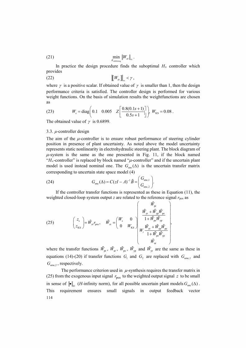
The obtained supremum in frequency domain for structure singular value is 0.89. The controller obtained is of 33th order. This order seems unnecessary high from practical point of view. Thus the controller order reduction should be done. The singular values plot of the -controllers of 33th and 6th orders are presented in Fig. 12. As can be seen the difference between singular values is negligibly small. That is why the -controller of 6th order will be implemented in microcontroller.
Fig. 12. Singular value frequency
response of -controller after 0.01 rad/s Fig. 13. Output sensitivity of uncertain closed-
loop system
4. Comparison of control systems
The results from comparison of frequency and time domain properties of LQG-system, H∞-system and -system are presented in this section. In comparison the uncertain plant model (3) is used. The characteristics of three control systems is evaluated for set of 50 various admissible values of plant uncertain parameters, obtained by Monte-Carlo simulation. The families of output sensitivity singular values and complementary sensitivity singular values, obtained by Matlab® R2016 function sigma, are shown in Figs 13 and 14.
It is seen that three systems have similar performance in low-frequency range, but the bandwidth of µ-system is approximately 4 rad/s, whereas ones of H∞-system and LQG system are 0.4 rad/s and 1 rad/s. This means that the µ-system can track 10 times faster reference signal than this of the LQG-system and 4 times faster than this
116
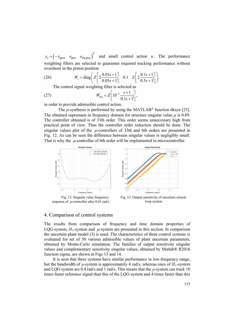
of H∞-system. The three systems will suppress very well low frequency disturbance, but again the µ-system has advantage over other two systems. In Fig. 15 the singular values of the three controllers are presented and in Fig. 16 the sensitivity of control signals to noise is shown.
Fig. 14. Complementary sensitivity of the
closed-loop system Fig. 15. Singular value frequency
response of controllers
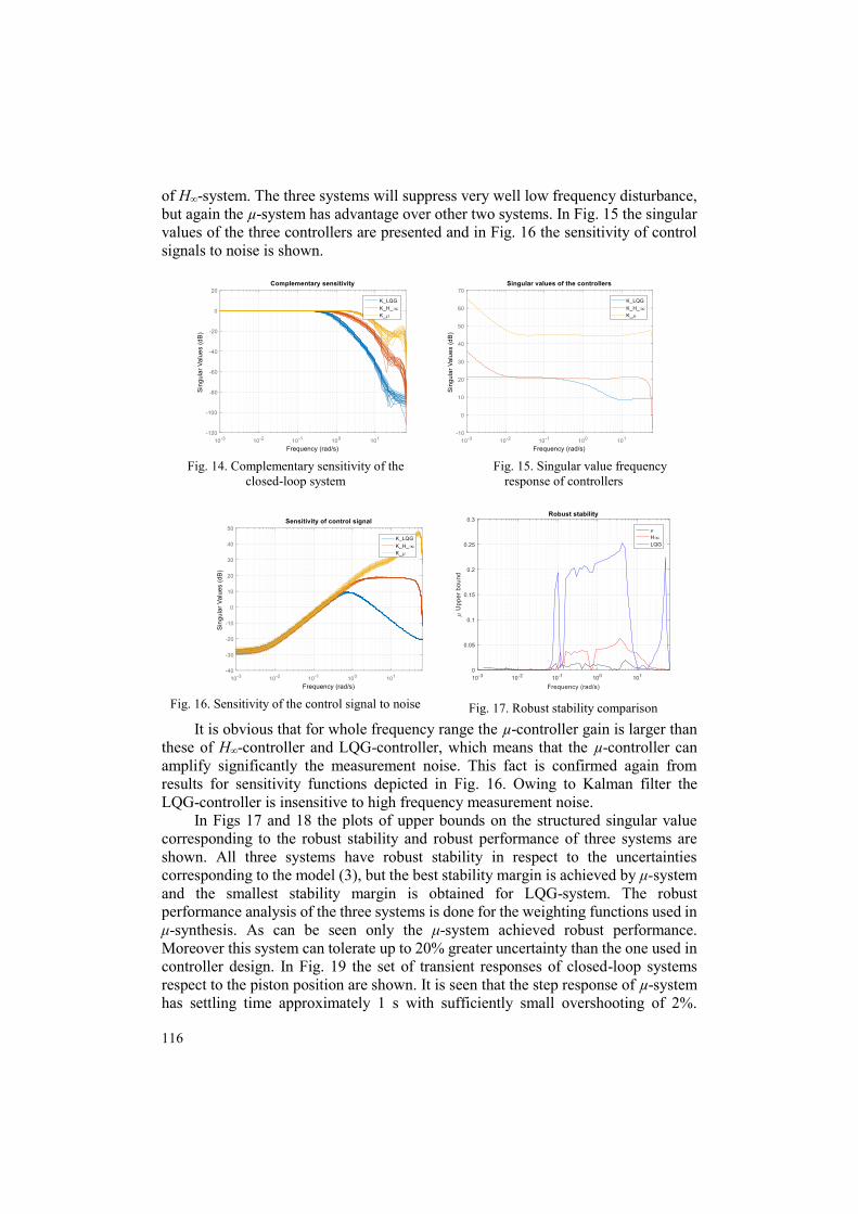
Fig. 16. Sensitivity of the control signal to noise Fig. 17. Robust stability comparison
It is obvious that for whole frequency range the µ-controller gain is larger than these of H∞-controller and LQG-controller, which means that the µ-controller can amplify significantly the measurement noise. This fact is confirmed again from results for sensitivity functions depicted in Fig. 16. Owing to Kalman filter the LQG-controller is insensitive to high frequency measurement noise.
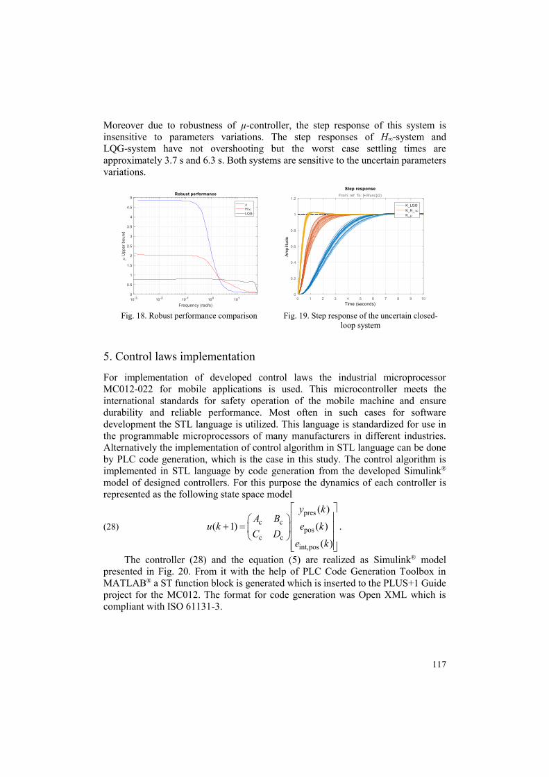
In Figs 17 and 18 the plots of upper bounds on the structured singular value corresponding to the robust stability and robust performance of three systems are shown. All three systems have robust stability in respect to the uncertainties corresponding to the model (3), but the best stability margin is achieved by μ-system and the smallest stability margin is obtained for LQG-system. The robust performance analysis of the three systems is done for the weighting functions used in μ-synthesis. As can be seen only the μ-system achieved robust performance. Moreover this system can tolerate up to 20% greater uncertainty than the one used in controller design. In Fig. 19 the set of transient responses of closed-loop systems respect to the piston position are shown. It is seen that the step response of µ-system has settling time approximately 1 s with sufficiently small overshooting of 2%.
117
Moreover due to robustness of µ-controller, the step response of this system is insensitive to parameters variations. The step responses of H∞-system and LQG-system have not overshooting but the worst case settling times are approximately 3.7 s and 6.3 s. Both systems are sensitive to the uncertain parameters variations.
Fig. 18. Robust performance comparison Fig. 19. Step response of the uncertain closed-
loop system
5. Control laws implementation
For implementation of developed control laws the industrial microprocessor MC012-022 for mobile applications is used. This microcontroller meets the international standards for safety operation of the mobile machine and ensure durability and reliable performance. Most often in such cases for software development the STL language is utilized. This language is standardized for use in the programmable microprocessors of many manufacturers in different industries. Alternatively the implementation of control algorithm in STL language can be done by PLC code generation, which is the case in this study. The control algorithm is implemented in STL language by code generation from the developed Simulink® model of designed controllers. For this purpose the dynamics of each controller is represented as the following state space model
(28) pres
c cpos
c cint,pos
( )
( 1) ( )
( )
y kA B
u k e kC D
e k
.
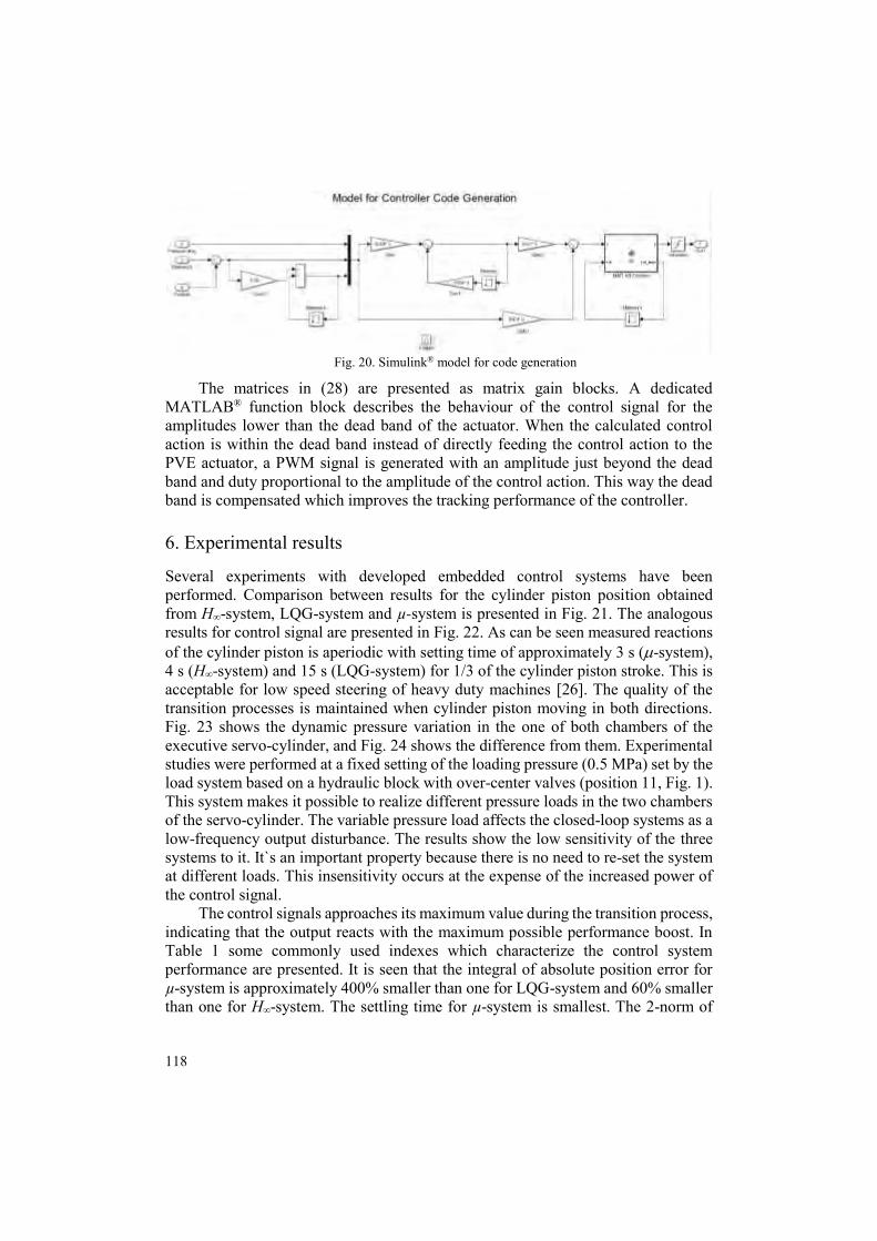
The controller (28) and the equation (5) are realized as Simulink® model presented in Fig. 20. From it with the help of PLC Code Generation Toolbox in MATLAB® a ST function block is generated which is inserted to the PLUS+1 Guide project for the MC012. The format for code generation was Open XML which is compliant with ISO 61131-3.
118
Fig. 20. Simulink® model for code generation
The matrices in (28) are presented as matrix gain blocks. A dedicated MATLAB® function block describes the behaviour of the control signal for the amplitudes lower than the dead band of the actuator. When the calculated control action is within the dead band instead of directly feeding the control action to the PVE actuator, a PWM signal is generated with an amplitude just beyond the dead band and duty proportional to the amplitude of the control action. This way the dead band is compensated which improves the tracking performance of the controller.
6. Experimental results
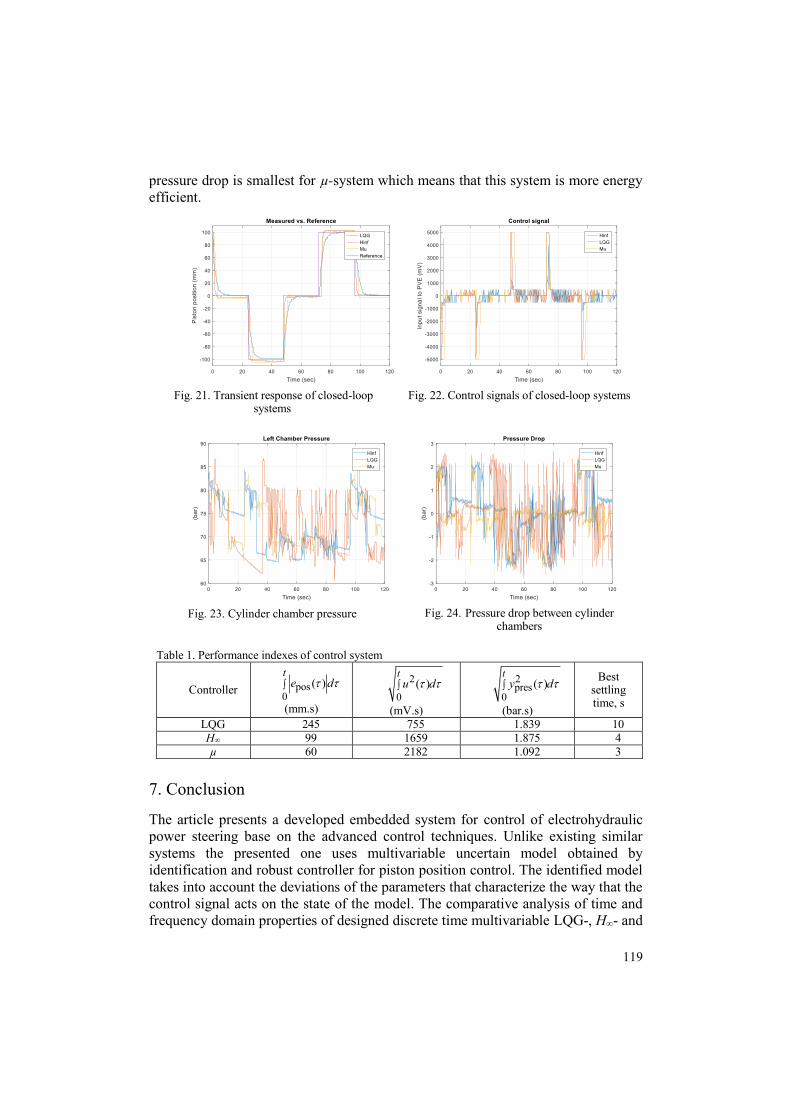
Several experiments with developed embedded control systems have been performed. Comparison between results for the cylinder piston position obtained from H∞-system, LQG-system and µ-system is presented in Fig. 21. The analogous results for control signal are presented in Fig. 22. As can be seen measured reactions of the cylinder piston is aperiodic with setting time of approximately 3 s (-system), 4 s (H∞-system) and 15 s (LQG-system) for 1/3 of the cylinder piston stroke. This is acceptable for low speed steering of heavy duty machines [26]. The quality of the transition processes is maintained when cylinder piston moving in both directions. Fig. 23 shows the dynamic pressure variation in the one of both chambers of the executive servo-cylinder, and Fig. 24 shows the difference from them. Experimental studies were performed at a fixed setting of the loading pressure (0.5 MPa) set by the load system based on a hydraulic block with over-center valves (position 11, Fig. 1). This system makes it possible to realize different pressure loads in the two chambers of the servo-cylinder. The variable pressure load affects the closed-loop systems as a low-frequency output disturbance. The results show the low sensitivity of the three systems to it. It`s an important property because there is no need to re-set the system at different loads. This insensitivity occurs at the expense of the increased power of the control signal.
The control signals approaches its maximum value during the transition process, indicating that the output reacts with the maximum possible performance boost. In Table 1 some commonly used indexes which characterize the control system performance are presented. It is seen that the integral of absolute position error for µ-system is approximately 400% smaller than one for LQG-system and 60% smaller than one for H∞-system. The settling time for µ-system is smallest. The 2-norm of
119
pressure drop is smallest for µ-system which means that this system is more energy efficient.
Fig. 21. Transient response of closed-loop
systems Fig. 22. Control signals of closed-loop systems
Fig. 23. Cylinder chamber pressure Fig. 24. Pressure drop between cylinder
chambers
Table 1. Performance indexes of control system
Controller pos0
( )t
e d
(mm.s)
2
0( )
tu d
(mV.s)
2pres
0( )
ty d
(bar.s)
Best settling time, s
LQG 245 755 1.839 10 H∞ 99 1659 1.875 4 µ 60 2182 1.092 3
7. Conclusion
The article presents a developed embedded system for control of electrohydraulic power steering base on the advanced control techniques. Unlike existing similar systems the presented one uses multivariable uncertain model obtained by identification and robust controller for piston position control. The identified model takes into account the deviations of the parameters that characterize the way that the control signal acts on the state of the model. The comparative analysis of time and frequency domain properties of designed discrete time multivariable LQG-, H∞- and
120
µ-controller is performed. The results obtained show the performance of system based on µ-controller. Also the robust stability and robust performance are investigated. All three systems achieve robust stability which guarantees their workability, but only the system with µ-controller has robust performance against prescribed uncertainties. The designed controllers are implemented in specialized 32-bit microcontroller. For this aim appropriate real time software is developed. A number of experiments have been executed, which confirm the quality of the electrohydraulic power steering control system. The presented experimental results show that the control systems achieves the prescribed performance, but the system based on µ-controller has significant advantages such as smallest settling time, smallest square error, and largest stability margin.
R e f e r e n c e s 1. B a c k é, W. Trends in Mobile Hydraulics. – In: Proc. of 4th Scandinavian International Conference
on Fluid Power, Tampere University, Vol. 1, Tampere, Finland, 1995. 2. M u r r e n h o f f, H., L. E c k s t e i. Fluidtechnik für mobile Anwendungen. Shaker-Verlag,
Germany, 2011. 3. K e m m e t m ü l l e r, W., S. M ü l l e r, A. K u g i. Mathematical Modeling and Nonlinear
Controller Design for a Novel Electrohydraulic Power-Steering System. – IEEE/ASME Transactions on Mechatronics, Vol. 12, 2007, No 1, pp. 85-97.
4. A n g e l o v, I., N. S t a n c h e v. Analysis and Synthesis of the Drive Hydraulic System for the Deep Injection Machine. – Journal of Food Packaging Science, Technique and Technologies, Vol. 2, 2013, No 2, pp. 159-163. ISSN 1314-7773.
5. A n g e l o v, I., N. S t a n c h e v. Analysis and Synthesis of an Electrohydraulic Closed Loop Control System for Drive of an Electrogenerator Device. – Journal of Food Packaging Science, Technique and Technologies, Vol. 4, 2013, No 3, pp. 14-19. ISSN 1314-7773.
6. P e t k o v, P., T. S l a v o v, J. K r a l e v. Design of Embedded Robust Control Systems Using MATLAB®/Simulink®”. IET Control, United Kingdom, 2018.
7. M á s, F., Q. Z h a n g et al. Mechatronics and Intelligent Systems for Off-Road Vehicles. London, Springer-Verlag, 2010.
8. Q i u, H., Q. Z h a n g. Feedforward-Plus-Proportional-Integral-Derivative Controller for an Off-Road Vehicle Electrohydraulic Steering System. – In: Proc. of Institution of Mechanical Engineers, Part D: Journal of Automobile Engineering, Vol. 217, 2003, pp. 375-382.
9. A t h e r t o n, D. P., S. M a j h i. Limitations of PID Controllers. – In: Americal Control Conference, Vol. 6, USA, 1999, pp. 3343-3847.
10. Å s t r ö m, K., T. H ä g g l u n d. The Future of PID Control. – Control Engineering Practice, Vol. 9, 2001, pp. 1163-1175.
11. B o u l e t, B., Y. D u a n. The Fundamental Tradeoff Betwen Performance and Robustness – A New Perspective on Loop Shaping – Classic Control Revisited. Part II. – IEEE Control Systems, Vol. 27, 2007, pp. 30-44.
12. Z h o u, K., J. C. D o y l e et al. Robust and Optimal Control. Upper Saddle River, NJ, Prentice Hall International, Inc., 1996.
13. G o o d w i n, G. C., S. F. G r a e b e, M. E. S a l g a d o. Control System Design. Upper Saddle River, NJ, Prentice-Hall, Inc., 2001.
14. L j u n g, L. System Identification: Theory for the User. 2nd Ed. Englewood Cliffs, NJ, Prentice-Hall, Inc., 1999.
15. I s e r m a n n, R., M. M u n c h h o f. Identification of Dynamic Systems. Springer, 2011. 16. M i t o v, A., J. K r a l e v, I. A n g e l o v, T. S l a v o v. Identification and Synthesis of Linear-
Quadratic Regulator for Digital Control of Electrohydraulic Steering System. – In: Proc. of 11th International Fluid Power Conference, Aachen, Germany, 2018.
121
17. M i t o v, A., T. S l a v o v, J. K r a l e v, I. A n g e l o v. H-Infinity Control of an Electrohydraulic Power Steering System. – In: Proc. of 41st International Conference on Telecommunications and Signal Processing (TSP’18), Athens, Greece, 2018, pp. 690-693.
18. K r a l e v, J., A. M i t o v, T. S l a v o v, I. A n g e l o v. Robust Mu-Controller for Electrohydraulic Steering System. – In: Proc. of 18th International Conference on Smart Technologies (EUROCON’19), Novi Sad, Serbia, 2019.
19. Danfoss. OSPE Steering Valve. Technical Information. 11068682. November 2016. 20. A n g e l o v, I., A. M i t o v. Test Bench for Experimental Research and Identification of
Electrohydraulic Steering Units. – In: 10th International Fluid Power Conference, Dresden, Germany, 2016.
21. S a u e r-D a n f o s s. Plus+1 Controllers MC012-020 and 022, Data Sheet, 11077167, Rev DA, 2013.
22. S ö d e r b e r g, A., J. H e d b e r g, P. F o l k e s s o n, J. J a c o b s o n. Safety and Transport Electronics – Safety-Related Machine Control Systems Using Standard EN ISO 13849-1. – In: Rise Report 1, Sweden, 2018.
23. F i s c h e r, E., et al. Safety Related Development of an Electro-Hydraulic Active Steering System. – In: Proc. of 18th ITI Symposium, Dresden, Germany, 2015, pp. 263-270.
24. P r o c a, A., A. K e y h a n i. Identification of Power Steering System Dynamic Models. – Mechatronics, Vol. 8, 1998, Elsevier, pp. 255-270.
25. The Mathworks, Inc. Robust Control Toolbox. User’s Guide. 2016. 26. D a h e r, N., M. I v a n t y s y n o v a. New Steering Concept for Wheel Loaders. – In: Proc. of 9th
International Fluid Power Conference, Aachen, Germany, 2014, pp. 224-235.
Received: 05.12.2019; Second Version: 21.02.2020; Accepted: 16.03.2020