Embed Size (px)
Citation preview
General Motors-AISI AAC Advanced High Strength Steel Repairability Study Phase II Final Report
Introduction The introduction of Advanced High Strength Steels (AHSS) to light vehicle body structure applications poses a significant challenge to organizations involved in the repair of vehicle structures. AHSS are typically produced by nontraditional thermal cycles and contain microstructural components whose mechanical properties can be altered by exposure to elevated temperatures. This temperature sensitivity could alter the mechanical behavior of AHSS after exposure to elevated temperatures during repair welding or flame straightening and could seriously affect the structural performance of AHSS components after repair. This study, requested by General Motors' Collision Repair Tech. Center, is the second phase of an on-going cooperative program between General Motors and North American steelmakers to evaluate the response and compatibility of AHSS to collision repair processes. The first phase [1] evaluated mild steel, HSLA 340 MPa yield strength, DP 600 MPa tensile strength, and 1300 MPa tensile strength martensitic steel products. In the first phase of this program, both the DP 600 and 1300 MPa tensile strength martensitic steels exhibited significant reduction in strength upon exposure to even the lowest flame straightening temperatures. Because higher strength DP steels and the TRIP steels all rely on strengthening mechanisms similar to those in the DP 600 steel, team members expressed concern that these steels may also be degraded by exposure to flame straightening temperatures. In this second phase, 780 MPa tensile strength dual phase and 600 and 780 MPa tensile strength TRIP products were evaluated to address these concerns. Phase II also began to address the effect of MIG repair welding on the mechanical properties of DP and TRIP steels to validate welding as a means to repair crash damage that cannot be repaired by conventional flame straightening. Phase II was conducted by a team composed of General Motors, AISI, and AISI Automotive Applications Committee steel company representatives. Team members included: Member Affiliation
Brian Dotterer General Motors Corporation Jim Fekete General Motors Corporation David Anderson AISI (AISI Coordinator) David Hoydick United States Steel Corporation Steve Kelley Bethlehem Steel Corporation (Now ISG Steel Corporation) Nassos Lazaridis Ispat Inland, Inc. Blake Zuidema National Steel Corp., now Ispat Inland, Inc. (Project Leader) The results, conclusions, and recommendations contained herein are the consensus views of the team members.
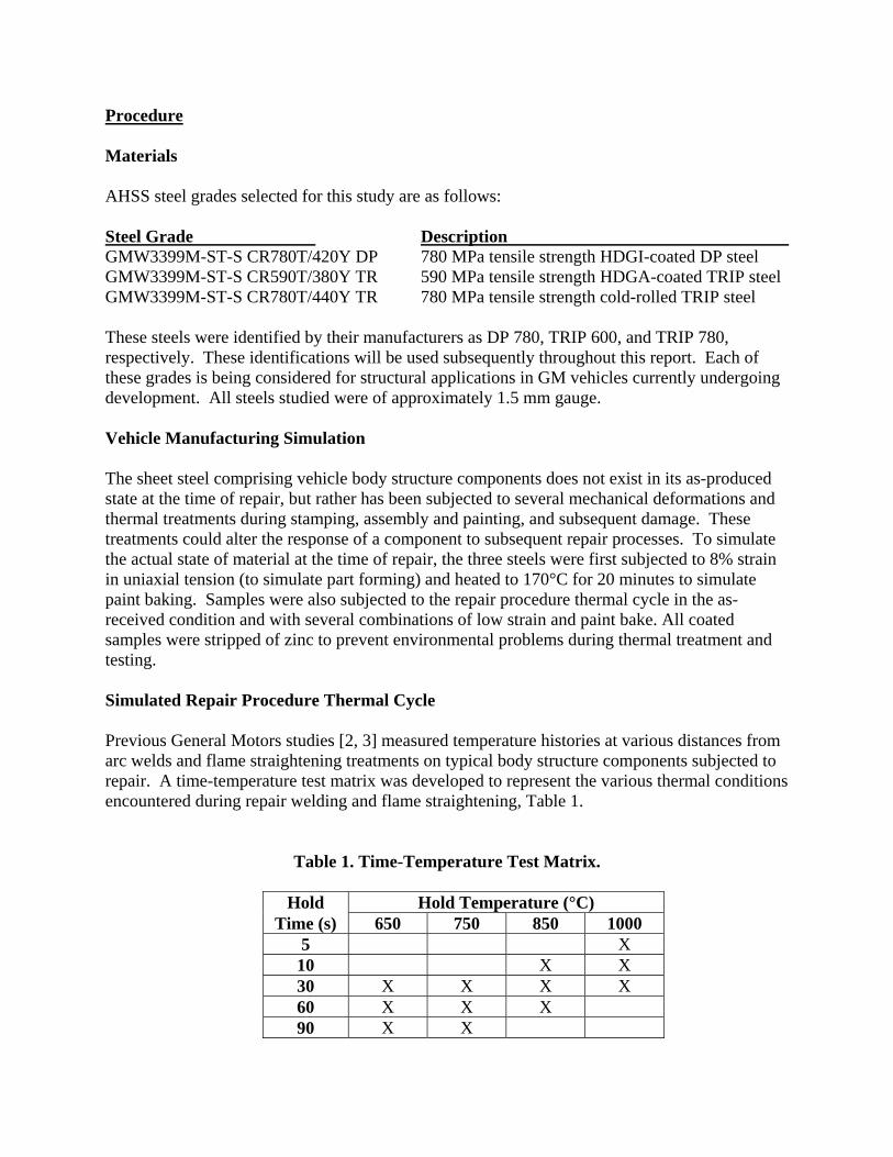
Procedure Materials AHSS steel grades selected for this study are as follows: Steel Grade Description GMW3399M-ST-S CR780T/420Y DP 780 MPa tensile strength HDGI-coated DP steel GMW3399M-ST-S CR590T/380Y TR 590 MPa tensile strength HDGA-coated TRIP steel GMW3399M-ST-S CR780T/440Y TR 780 MPa tensile strength cold-rolled TRIP steel These steels were identified by their manufacturers as DP 780, TRIP 600, and TRIP 780, respectively. These identifications will be used subsequently throughout this report. Each of these grades is being considered for structural applications in GM vehicles currently undergoing development. All steels studied were of approximately 1.5 mm gauge. Vehicle Manufacturing Simulation The sheet steel comprising vehicle body structure components does not exist in its as-produced state at the time of repair, but rather has been subjected to several mechanical deformations and thermal treatments during stamping, assembly and painting, and subsequent damage. These treatments could alter the response of a component to subsequent repair processes. To simulate the actual state of material at the time of repair, the three steels were first subjected to 8% strain in uniaxial tension (to simulate part forming) and heated to 170°C for 20 minutes to simulate paint baking. Samples were also subjected to the repair procedure thermal cycle in the as-received condition and with several combinations of low strain and paint bake. All coated samples were stripped of zinc to prevent environmental problems during thermal treatment and testing. Simulated Repair Procedure Thermal Cycle Previous General Motors studies [2, 3] measured temperature histories at various distances from arc welds and flame straightening treatments on typical body structure components subjected to repair. A time-temperature test matrix was developed to represent the various thermal conditions encountered during repair welding and flame straightening, Table 1.
Table 1. Time-Temperature Test Matrix.
Hold Hold Temperature (°C) Time (s) 650 750 850 1000
5 X 10 X X 30 X X X X 60 X X X 90 X X
Two additional cycles were simulated. Samples were heated to 750 °C for 90 seconds, with intermediate cooling briefly to below 538 °C after 30 and 60 seconds (to simulate multiple flame heating cycles). Samples of DP and TRIP steels without prestrain and paint baking (as-received condition) were subjected to the 650 °C, 90 second thermal treatment. Mechanical Testing Standard ASTM tensile tests were conducted on samples in the as-received condition, after straining and paint baking, and after the indicated thermal treatments. Results for two samples were averaged and yield strength (YS), ultimate tensile strength (UTS), uniform elongation (UEL), total elongation (TEL), and n-value were reported and plotted against temperature for each hold time. n-values were calculated in the 10% to end of uniform elongation strain range The AC1 and AC3 temperatures (phase boundaries) for each steel grade were provided by the steel manufacturers and are indicated on the property-temperature plots. Response to MIG welding To begin assessing the response of AHSS to repair MIG welding, selected samples of Phase I and Phase II steels were MIG welded at GM's Service Parts Operations Warren, MI repair lab. Samples subjected to MIG welding included the HSLA 340 and DP 600 steels from Phase I and the DP 780 and TRIP 600 steels from Phase II. Samples of each steel were prepared in two conditions: 1.) strained 8% in tension and paint baked, and 2.) strained 8% in tension, paing baked, and heated to 650 °C for 90 seconds. Samples measuring 2" wide by 8" long were prepared. A single MIG weld bead was placed at the center of each sample, transverse to the long direction, at a welding speed sufficient to assure complete weld penetration through the thickness. Other welding conditions were as follow: Welder: Miller 190 MIG, 220V, Single Phase Welder Settings: Gas = 20 PSI, 75% Ar/25% CO2 Wire Speed Setting = 53 Voltage Setting = 3 to 4 Filler Wire: 0.023" Harris-Welco Welco-Matic ER70S-6 After welding, standard 2" gauge length ASTM weld coupons were machined from the weldments, with the MIG weld beads at the center of the reduced gauge section and the weld bead transverse to the gauge length. The weld beads themselves were not removed. Test coupons were pulled under standard ASTM testing conditions. Tensile test results from the welded coupons were compared to those for the base (unwelded) condition and for the as received condition.
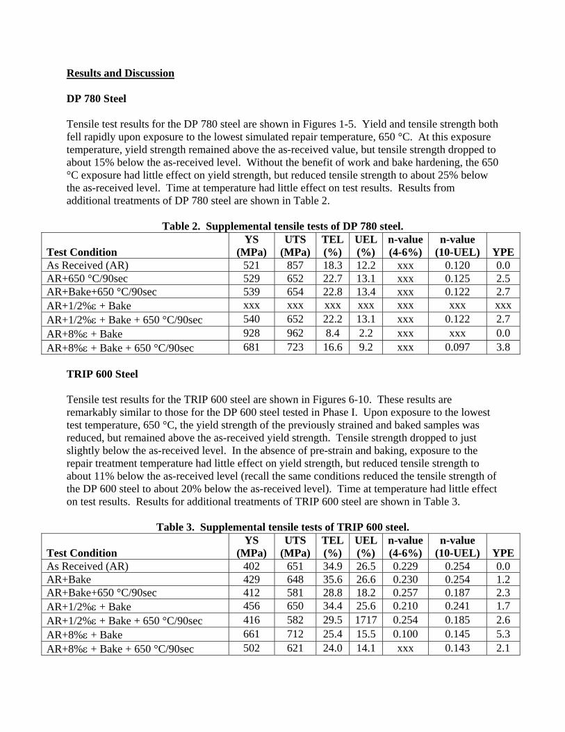
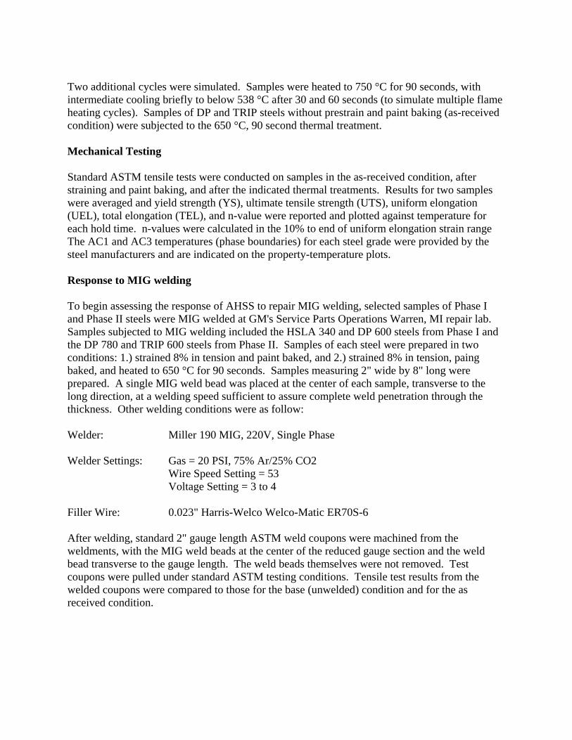
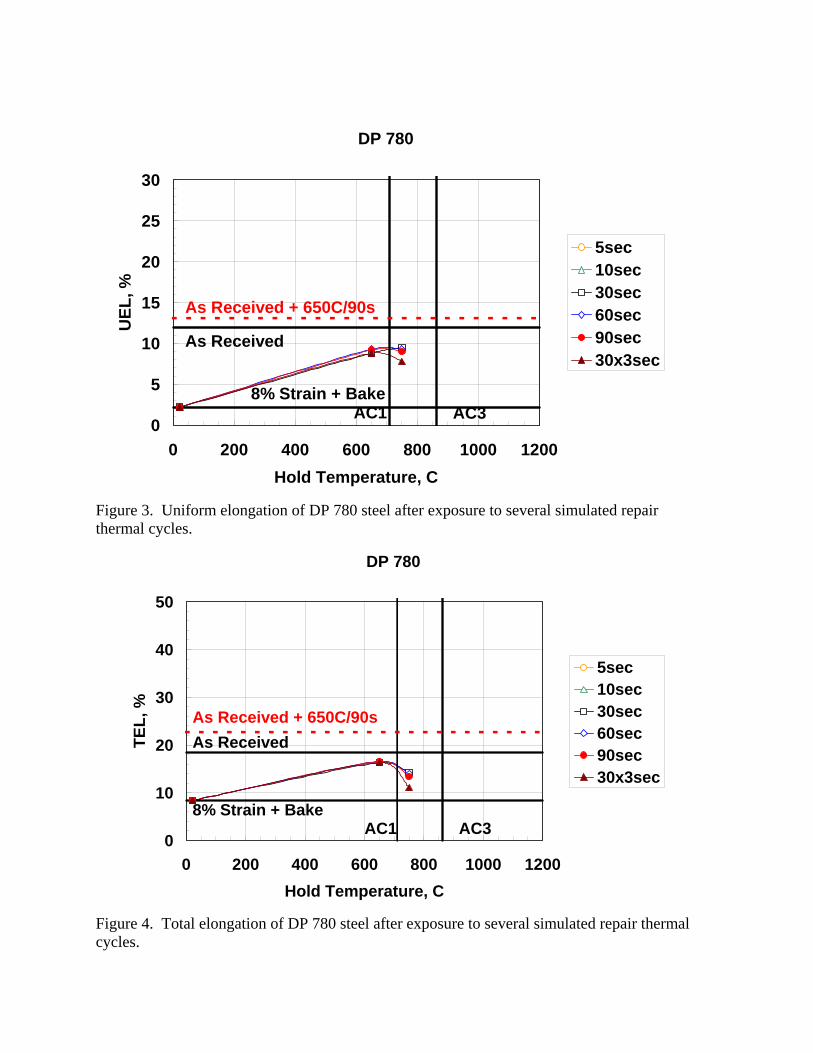
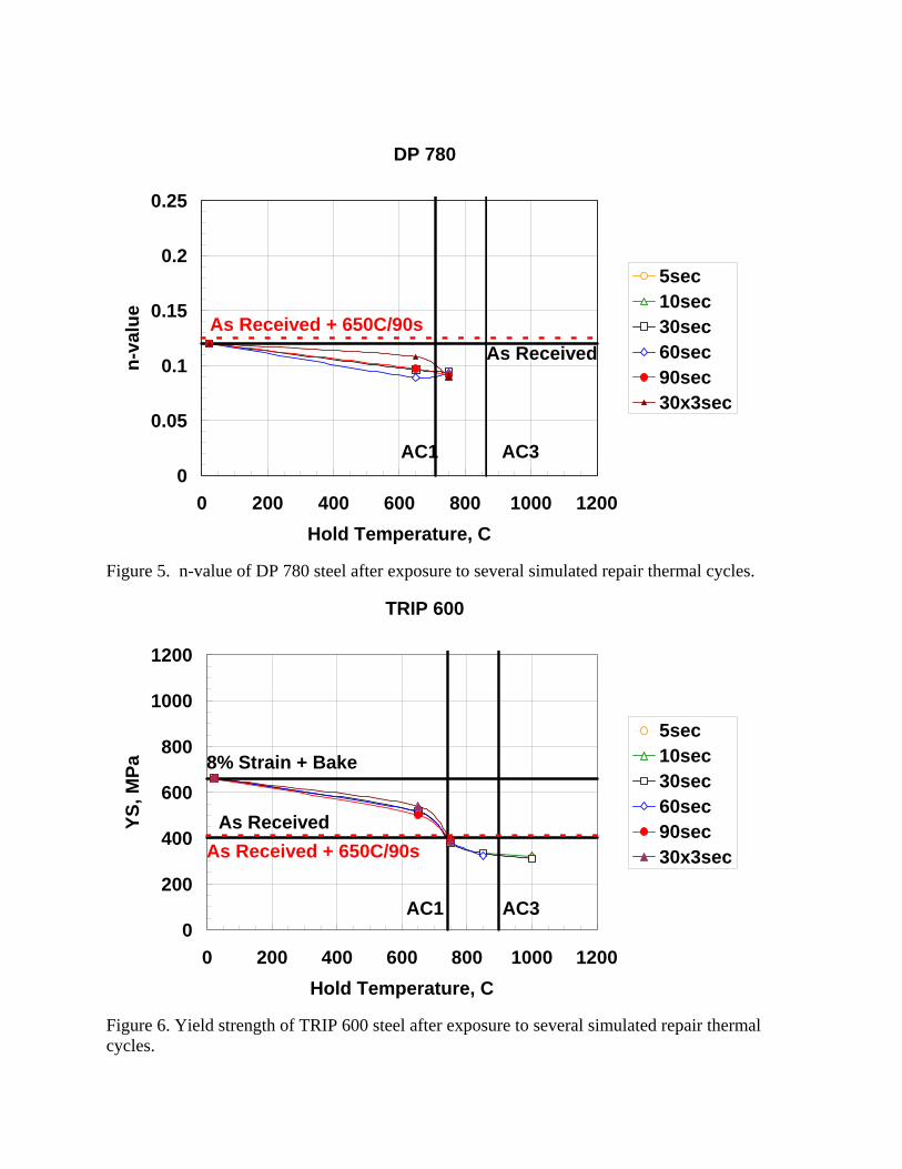
Results and Discussion DP 780 Steel Tensile test results for the DP 780 steel are shown in Figures 1-5. Yield and tensile strength both fell rapidly upon exposure to the lowest simulated repair temperature, 650 °C. At this exposure temperature, yield strength remained above the as-received value, but tensile strength dropped to about 15% below the as-received level. Without the benefit of work and bake hardening, the 650 °C exposure had little effect on yield strength, but reduced tensile strength to about 25% below the as-received level. Time at temperature had little effect on test results. Results from additional treatments of DP 780 steel are shown in Table 2.
Table 2. Supplemental tensile tests of DP 780 steel. Test Condition
YS (MPa)
UTS (MPa)
TEL(%)
UEL(%)
n-value (4-6%)
n-value (10-UEL)
YPE
As Received (AR) 521 857 18.3 12.2 xxx 0.120 0.0 AR+650 °C/90sec 529 652 22.7 13.1 xxx 0.125 2.5 AR+Bake+650 °C/90sec 539 654 22.8 13.4 xxx 0.122 2.7 AR+1/2%ε + Bake xxx xxx xxx xxx xxx xxx xxx AR+1/2%ε + Bake + 650 °C/90sec 540 652 22.2 13.1 xxx 0.122 2.7 AR+8%ε + Bake 928 962 8.4 2.2 xxx xxx 0.0 AR+8%ε + Bake + 650 °C/90sec 681 723 16.6 9.2 xxx 0.097 3.8
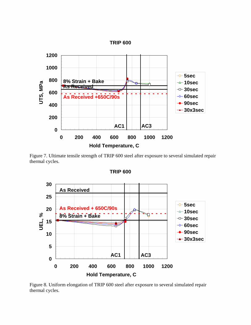
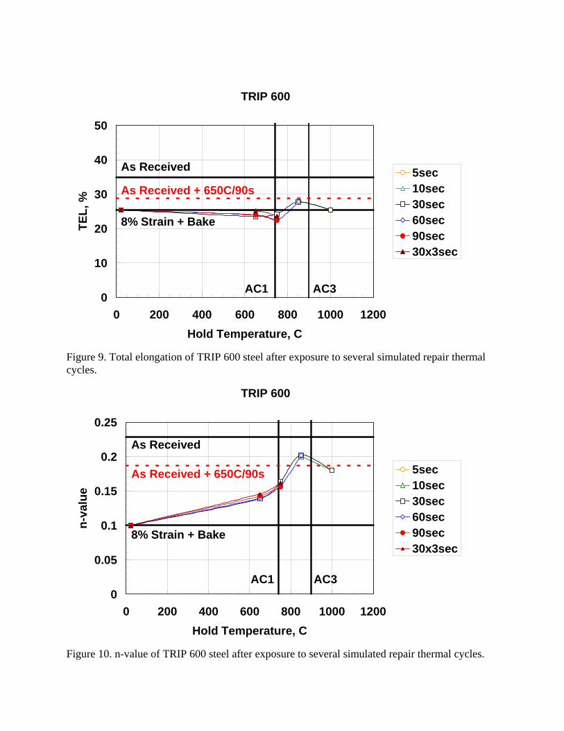
TRIP 600 Steel Tensile test results for the TRIP 600 steel are shown in Figures 6-10. These results are remarkably similar to those for the DP 600 steel tested in Phase I. Upon exposure to the lowest test temperature, 650 °C, the yield strength of the previously strained and baked samples was reduced, but remained above the as-received yield strength. Tensile strength dropped to just slightly below the as-received level. In the absence of pre-strain and baking, exposure to the repair treatment temperature had little effect on yield strength, but reduced tensile strength to about 11% below the as-received level (recall the same conditions reduced the tensile strength of the DP 600 steel to about 20% below the as-received level). Time at temperature had little effect on test results. Results for additional treatments of TRIP 600 steel are shown in Table 3.
Table 3. Supplemental tensile tests of TRIP 600 steel. Test Condition
YS (MPa)
UTS (MPa)
TEL(%)
UEL(%)
n-value (4-6%)
n-value (10-UEL)
YPE
As Received (AR) 402 651 34.9 26.5 0.229 0.254 0.0 AR+Bake 429 648 35.6 26.6 0.230 0.254 1.2 AR+Bake+650 °C/90sec 412 581 28.8 18.2 0.257 0.187 2.3 AR+1/2%ε + Bake 456 650 34.4 25.6 0.210 0.241 1.7 AR+1/2%ε + Bake + 650 °C/90sec 416 582 29.5 1717 0.254 0.185 2.6 AR+8%ε + Bake 661 712 25.4 15.5 0.100 0.145 5.3 AR+8%ε + Bake + 650 °C/90sec 502 621 24.0 14.1 xxx 0.143 2.1
DP 780
0
200
400
600
800
1000
1200
0 200 400 600 800 1000 1200Hold Temperature, C
YS, M
Pa
5sec10sec30sec60sec90sec30x3sec
8% Strain + Bake
As Received
AC1 AC3
As Received + 650C/90s
Figure 1. Yield strength of DP 780 steel after exposure to several simulated repair thermal cycles.
DP 780
0
200
400
600
800
1000
1200
0 200 400 600 800 1000 1200Hold Temperature, C
UTS
, MPa
5sec10sec30sec60sec90sec30x3sec
8% Strain + BakeAs Received
AC1 AC3
As Received +650C/90s
Figure 2. Ultimate tensile strength of DP 780 steel after exposure to several simulated repair thermal cycles.
DP 780
0
5
10
15
20
25
30
0 200 400 600 800 1000 1200Hold Temperature, C
UEL
, %
5sec10sec30sec60sec90sec30x3sec
8% Strain + Bake
As Received
AC1 AC3
As Received + 650C/90s
Figure 3. Uniform elongation of DP 780 steel after exposure to several simulated repair thermal cycles.
DP 780
0
10
20
30
40
50
0 200 400 600 800 1000 1200Hold Temperature, C
TEL,
%
5sec10sec30sec60sec90sec30x3sec
8% Strain + Bake
As Received
AC1 AC3
As Received + 650C/90s
Figure 4. Total elongation of DP 780 steel after exposure to several simulated repair thermal cycles.
DP 780
0
0.05
0.1
0.15
0.2
0.25
0 200 400 600 800 1000 1200Hold Temperature, C
n-va
lue
5sec10sec30sec60sec90sec30x3sec
As Received + 650C/90s
AC1 AC3
As Received
Figure 5. n-value of DP 780 steel after exposure to several simulated repair thermal cycles.
TRIP 600
0
200
400
600
800
1000
1200
0 200 400 600 800 1000 1200Hold Temperature, C
YS, M
Pa
5sec10sec30sec60sec90sec30x3sec
8% Strain + Bake
As Received
AC1 AC3
As Received + 650C/90s
Figure 6. Yield strength of TRIP 600 steel after exposure to several simulated repair thermal cycles.
TRIP 600
0
200
400
600
800
1000
1200
0 200 400 600 800 1000 1200Hold Temperature, C
UTS
, MPa
5sec10sec30sec60sec90sec30x3sec
8% Strain + BakeAs Received
AC1 AC3
As Received +650C/90s
Figure 7. Ultimate tensile strength of TRIP 600 steel after exposure to several simulated repair thermal cycles.
TRIP 600
0
5
10
15
20
25
30
0 200 400 600 800 1000 1200Hold Temperature, C
UEL
, %
5sec10sec30sec60sec90sec30x3sec
8% Strain + Bake
As Received
AC1 AC3
As Received + 650C/90s
Figure 8. Uniform elongation of TRIP 600 steel after exposure to several simulated repair thermal cycles.
TRIP 600
0
10
20
30
40
50
0 200 400 600 800 1000 1200Hold Temperature, C
TEL,
%
5sec10sec30sec60sec90sec30x3sec
8% Strain + Bake
As Received
AC1 AC3
As Received + 650C/90s
Figure 9. Total elongation of TRIP 600 steel after exposure to several simulated repair thermal cycles.
TRIP 600
0
0.05
0.1
0.15
0.2
0.25
0 200 400 600 800 1000 1200Hold Temperature, C
n-va
lue
5sec10sec30sec60sec90sec30x3sec
As Received + 650C/90s
AC1 AC3
As Received
8% Strain + Bake
Figure 10. n-value of TRIP 600 steel after exposure to several simulated repair thermal cycles.
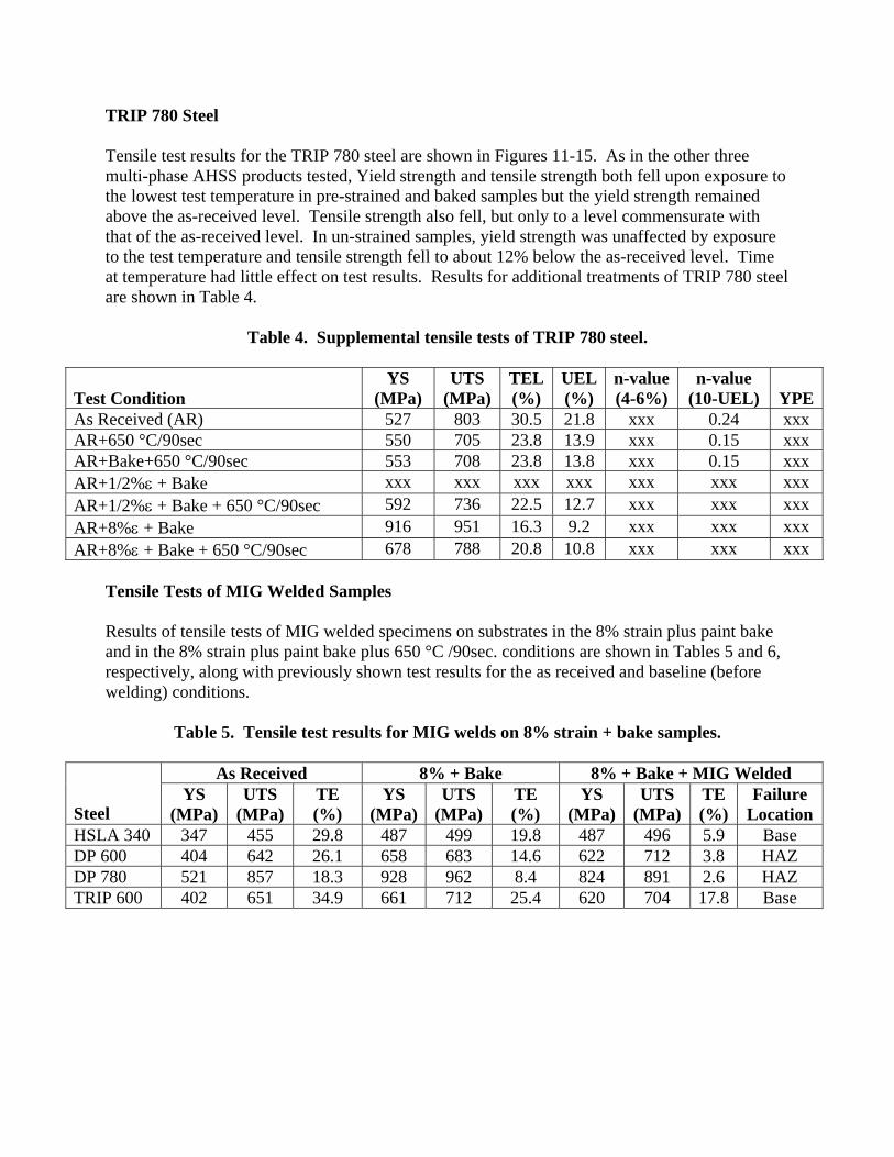
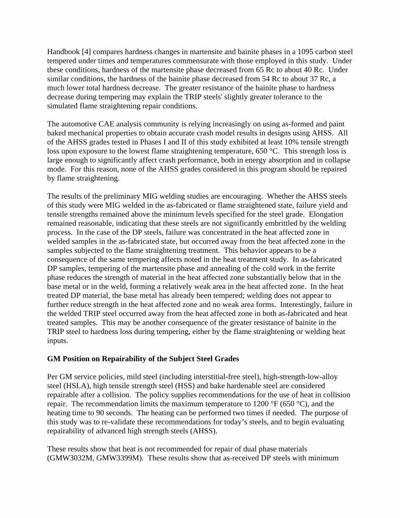
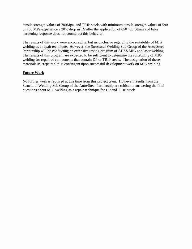
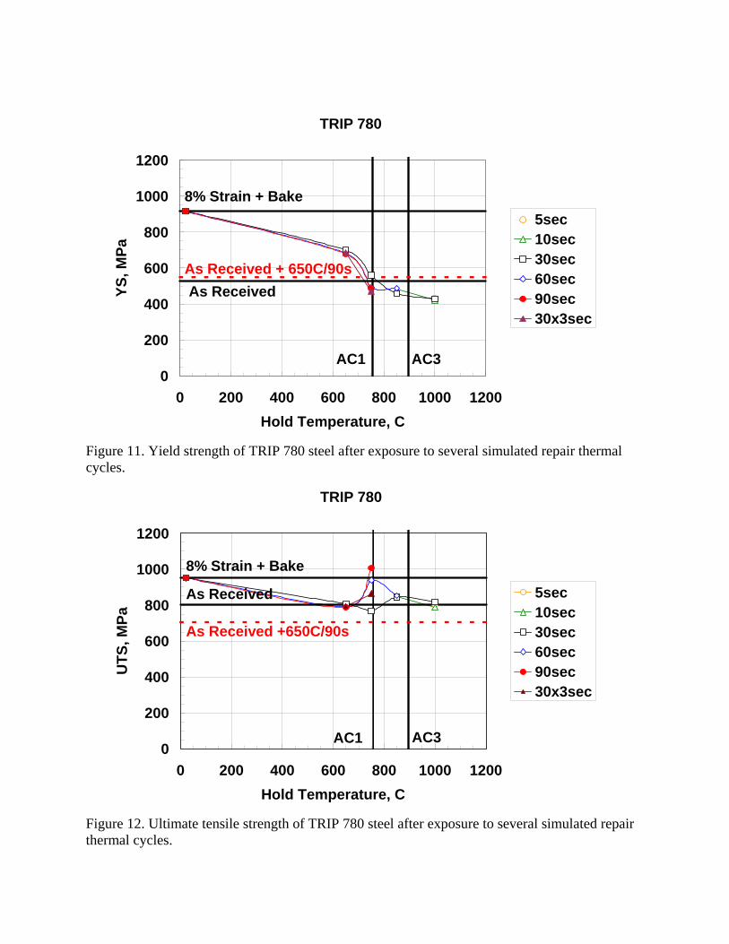
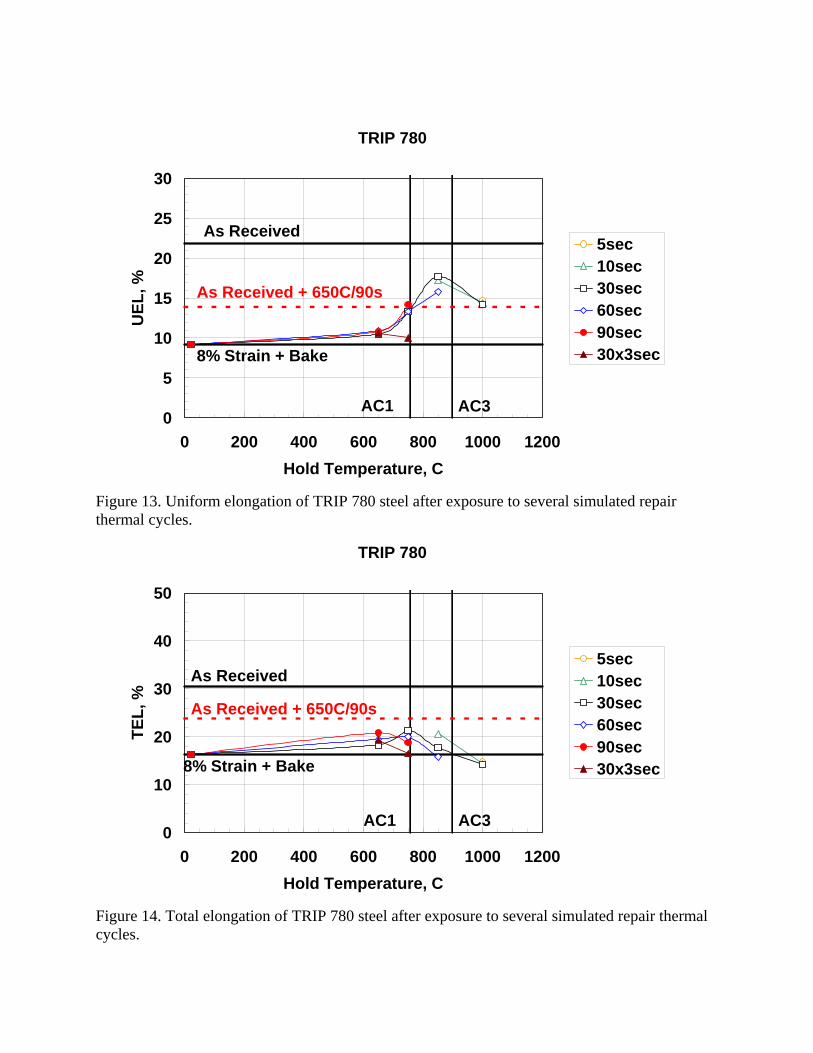
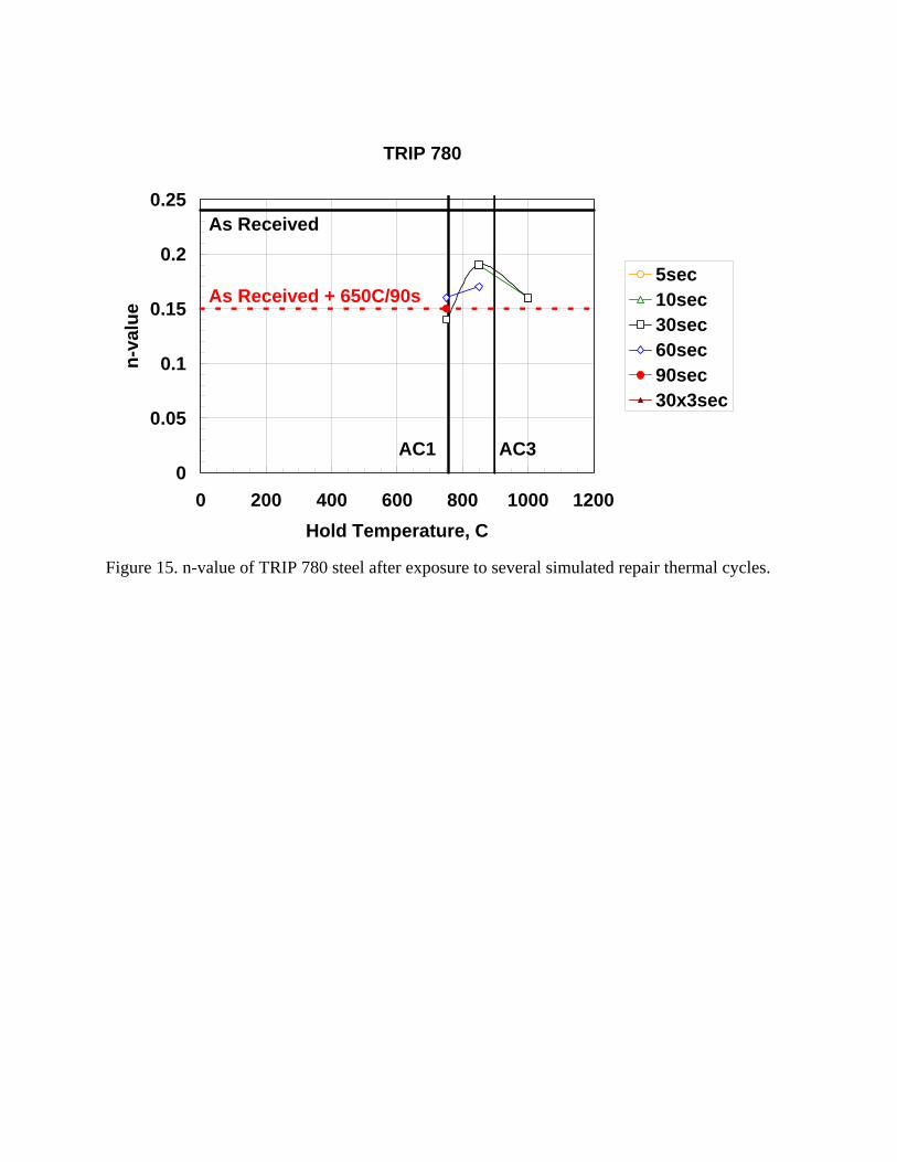
TRIP 780 Steel Tensile test results for the TRIP 780 steel are shown in Figures 11-15. As in the other three multi-phase AHSS products tested, Yield strength and tensile strength both fell upon exposure to the lowest test temperature in pre-strained and baked samples but the yield strength remained above the as-received level. Tensile strength also fell, but only to a level commensurate with that of the as-received level. In un-strained samples, yield strength was unaffected by exposure to the test temperature and tensile strength fell to about 12% below the as-received level. Time at temperature had little effect on test results. Results for additional treatments of TRIP 780 steel are shown in Table 4.
Table 4. Supplemental tensile tests of TRIP 780 steel.
Test Condition
YS (MPa)
UTS (MPa)
TEL(%)
UEL(%)
n-value (4-6%)
n-value (10-UEL)
YPE
As Received (AR) 527 803 30.5 21.8 xxx 0.24 xxx AR+650 °C/90sec 550 705 23.8 13.9 xxx 0.15 xxx AR+Bake+650 °C/90sec 553 708 23.8 13.8 xxx 0.15 xxx AR+1/2%ε + Bake xxx xxx xxx xxx xxx xxx xxx AR+1/2%ε + Bake + 650 °C/90sec 592 736 22.5 12.7 xxx xxx xxx AR+8%ε + Bake 916 951 16.3 9.2 xxx xxx xxx AR+8%ε + Bake + 650 °C/90sec 678 788 20.8 10.8 xxx xxx xxx
Tensile Tests of MIG Welded Samples Results of tensile tests of MIG welded specimens on substrates in the 8% strain plus paint bake and in the 8% strain plus paint bake plus 650 °C /90sec. conditions are shown in Tables 5 and 6, respectively, along with previously shown test results for the as received and baseline (before welding) conditions.
Table 5. Tensile test results for MIG welds on 8% strain + bake samples.
As Received 8% + Bake 8% + Bake + MIG Welded Steel
YS (MPa)
UTS (MPa)
TE (%)
YS (MPa)
UTS (MPa)
TE (%)
YS (MPa)
UTS (MPa)
TE (%)
Failure Location
HSLA 340 347 455 29.8 487 499 19.8 487 496 5.9 Base DP 600 404 642 26.1 658 683 14.6 622 712 3.8 HAZ DP 780 521 857 18.3 928 962 8.4 824 891 2.6 HAZ TRIP 600 402 651 34.9 661 712 25.4 620 704 17.8 Base
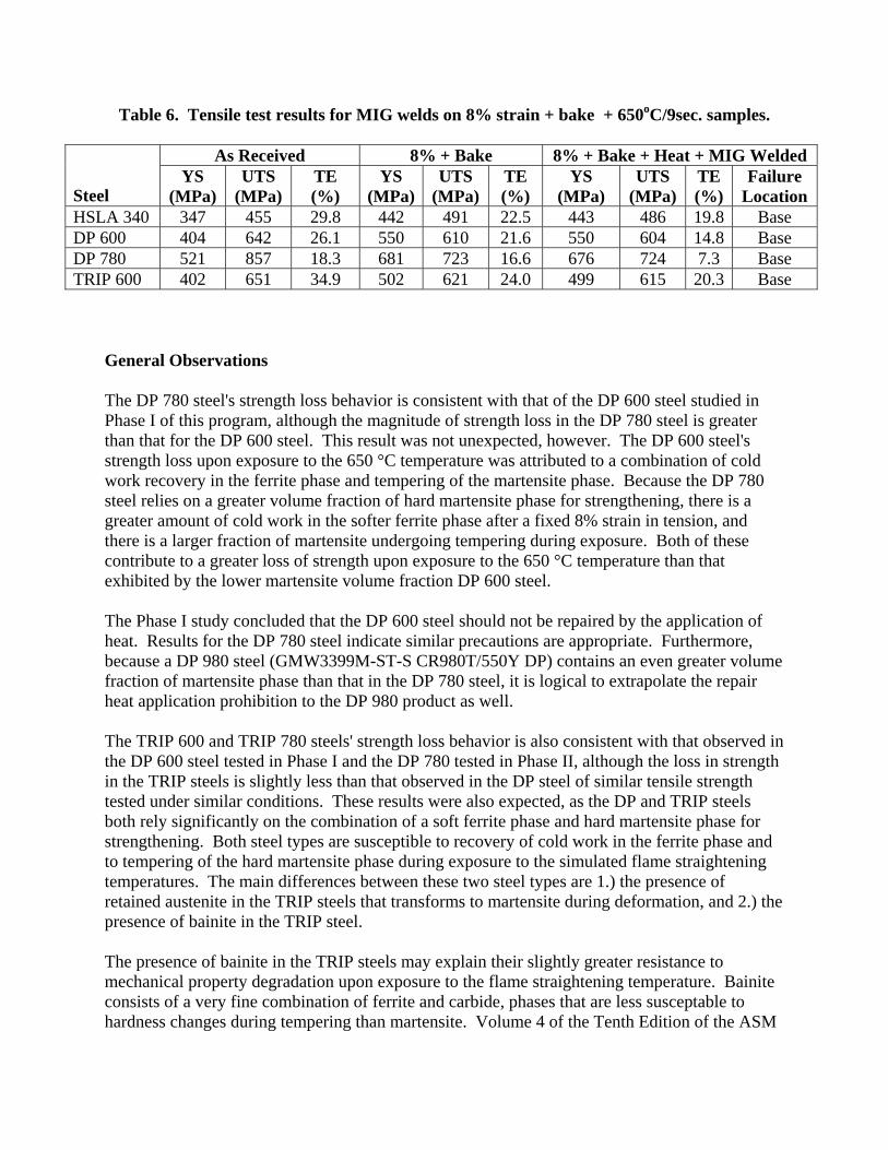
Table 6. Tensile test results for MIG welds on 8% strain + bake + 650oC/9sec. samples.
As Received 8% + Bake 8% + Bake + Heat + MIG Welded Steel
YS (MPa)
UTS (MPa)
TE (%)
YS (MPa)
UTS (MPa)
TE (%)
YS (MPa)
UTS (MPa)
TE (%)
Failure Location
HSLA 340 347 455 29.8 442 491 22.5 443 486 19.8 Base DP 600 404 642 26.1 550 610 21.6 550 604 14.8 Base DP 780 521 857 18.3 681 723 16.6 676 724 7.3 Base TRIP 600 402 651 34.9 502 621 24.0 499 615 20.3 Base
General Observations The DP 780 steel's strength loss behavior is consistent with that of the DP 600 steel studied in Phase I of this program, although the magnitude of strength loss in the DP 780 steel is greater than that for the DP 600 steel. This result was not unexpected, however. The DP 600 steel's strength loss upon exposure to the 650 °C temperature was attributed to a combination of cold work recovery in the ferrite phase and tempering of the martensite phase. Because the DP 780 steel relies on a greater volume fraction of hard martensite phase for strengthening, there is a greater amount of cold work in the softer ferrite phase after a fixed 8% strain in tension, and there is a larger fraction of martensite undergoing tempering during exposure. Both of these contribute to a greater loss of strength upon exposure to the 650 °C temperature than that exhibited by the lower martensite volume fraction DP 600 steel. The Phase I study concluded that the DP 600 steel should not be repaired by the application of heat. Results for the DP 780 steel indicate similar precautions are appropriate. Furthermore, because a DP 980 steel (GMW3399M-ST-S CR980T/550Y DP) contains an even greater volume fraction of martensite phase than that in the DP 780 steel, it is logical to extrapolate the repair heat application prohibition to the DP 980 product as well. The TRIP 600 and TRIP 780 steels' strength loss behavior is also consistent with that observed in the DP 600 steel tested in Phase I and the DP 780 tested in Phase II, although the loss in strength in the TRIP steels is slightly less than that observed in the DP steel of similar tensile strength tested under similar conditions. These results were also expected, as the DP and TRIP steels both rely significantly on the combination of a soft ferrite phase and hard martensite phase for strengthening. Both steel types are susceptible to recovery of cold work in the ferrite phase and to tempering of the hard martensite phase during exposure to the simulated flame straightening temperatures. The main differences between these two steel types are 1.) the presence of retained austenite in the TRIP steels that transforms to martensite during deformation, and 2.) the presence of bainite in the TRIP steel. The presence of bainite in the TRIP steels may explain their slightly greater resistance to mechanical property degradation upon exposure to the flame straightening temperature. Bainite consists of a very fine combination of ferrite and carbide, phases that are less susceptable to hardness changes during tempering than martensite. Volume 4 of the Tenth Edition of the ASM
Handbook [4] compares hardness changes in martensite and bainite phases in a 1095 carbon steel tempered under times and temperatures commensurate with those employed in this study. Under these conditions, hardness of the martensite phase decreased from 65 Rc to about 40 Rc. Under similar conditions, the hardness of the bainite phase decreased from 54 Rc to about 37 Rc, a much lower total hardness decrease. The greater resistance of the bainite phase to hardness decrease during tempering may explain the TRIP steels' slightly greater tolerance to the simulated flame straightening repair conditions. The automotive CAE analysis community is relying increasingly on using as-formed and paint baked mechanical properties to obtain accurate crash model results in designs using AHSS. All of the AHSS grades tested in Phases I and II of this study exhibited at least 10% tensile strength loss upon exposure to the lowest flame straightening temperature, 650 °C. This strength loss is large enough to significantly affect crash performance, both in energy absorption and in collapse mode. For this reason, none of the AHSS grades considered in this program should be repaired by flame straightening. The results of the preliminary MIG welding studies are encouraging. Whether the AHSS steels of this study were MIG welded in the as-fabricated or flame straightened state, failure yield and tensile strengths remained above the minimum levels specified for the steel grade. Elongation remained reasonable, indicating that these steels are not significantly embrittled by the welding process. In the case of the DP steels, failure was concentrated in the heat affected zone in welded samples in the as-fabricated state, but occurred away from the heat affected zone in the samples subjected to the flame straightening treatment. This behavior appears to be a consequence of the same tempering affects noted in the heat treatment study. In as-fabricated DP samples, tempering of the martensite phase and annealing of the cold work in the ferrite phase reduces the strength of material in the heat affected zone substantially below that in the base metal or in the weld, forming a relatively weak area in the heat affected zone. In the heat treated DP material, the base metal has already been tempered; welding does not appear to further reduce strength in the heat affected zone and no weak area forms. Interestingly, failure in the welded TRIP steel occurred away from the heat affected zone in both as-fabricated and heat treated samples. This may be another consequence of the greater resistance of bainite in the TRIP steel to hardness loss during tempering, either by the flame straightening or welding heat inputs. GM Position on Repairability of the Subject Steel Grades Per GM service policies, mild steel (including interstitial-free steel), high-strength-low-alloy steel (HSLA), high tensile strength steel (HSS) and bake hardenable steel are considered repairable after a collision. The policy supplies recommendations for the use of heat in collision repair. The recommendation limits the maximum temperature to 1200 °F (650 °C), and the heating time to 90 seconds. The heating can be performed two times if needed. The purpose of this study was to re-validate these recommendations for today’s steels, and to begin evaluating repairability of advanced high strength steels (AHSS). These results show that heat is not recommended for repair of dual phase materials (GMW3032M, GMW3399M). These results show that as-received DP steels with minimum
tensile strength values of 780Mpa, and TRIP steels with minimum tensile strength values of 590 or 780 MPa experience a 20% drop in TS after the application of 650 °C. Strain and bake hardening response does not counteract this behavior. The results of this work were encouraging, but inconclusive regarding the suitability of MIG welding as a repair technique. However, the Structural Welding Sub Group of the Auto/Steel Partnership will be conducting an extensive testing program of AHSS MIG and laser welding. The results of this program are expected to be sufficient to determine the suitablility of MIG welding for repair of components that contain DP or TRIP steels. The designation of these materials as “repairable” is contingent upon successful development work on MIG welding Future Work No further work is required at this time from this project team. However, results from the Structural Welding Sub Group of the Auto/Steel Partnership are critical to answering the final questions about MIG welding as a repair technique for DP and TRIP steels.
TRIP 780
0
200
400
600
800
1000
1200
0 200 400 600 800 1000 1200Hold Temperature, C
YS, M
Pa
5sec10sec30sec60sec90sec30x3sec
8% Strain + Bake
As Received
AC1 AC3
As Received + 650C/90s
Figure 11. Yield strength of TRIP 780 steel after exposure to several simulated repair thermal cycles.
TRIP 780
0
200
400
600
800
1000
1200
0 200 400 600 800 1000 1200Hold Temperature, C
UTS
, MPa
5sec10sec30sec60sec90sec30x3sec
8% Strain + Bake
As Received
AC1 AC3
As Received +650C/90s
Figure 12. Ultimate tensile strength of TRIP 780 steel after exposure to several simulated repair thermal cycles.
TRIP 780
0
5
10
15
20
25
30
0 200 400 600 800 1000 1200Hold Temperature, C
UEL
, %
5sec10sec30sec60sec90sec30x3sec8% Strain + Bake
As Received
AC1 AC3
As Received + 650C/90s
Figure 13. Uniform elongation of TRIP 780 steel after exposure to several simulated repair thermal cycles.
TRIP 780
0
10
20
30
40
50
0 200 400 600 800 1000 1200Hold Temperature, C
TEL,
%
5sec10sec30sec60sec90sec30x3sec8% Strain + Bake
As Received
AC1 AC3
As Received + 650C/90s
Figure 14. Total elongation of TRIP 780 steel after exposure to several simulated repair thermal cycles.
TRIP 780
0
0.05
0.1
0.15
0.2
0.25
0 200 400 600 800 1000 1200Hold Temperature, C
n-va
lue
5sec10sec30sec60sec90sec30x3sec
As Received + 650C/90s
AC1 AC3
As Received
Figure 15. n-value of TRIP 780 steel after exposure to several simulated repair thermal cycles.
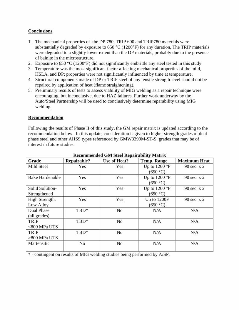
Conclusions 1. The mechanical properties of the DP 780, TRIP 600 and TRIP780 materials were
substantially degraded by exposure to 650 °C (1200°F) for any duration, The TRIP materials were degraded to a slightly lower extent than the DP materials, probably due to the presence of bainite in the microstructure.
2. Exposure to 650 °C (1200°F) did not significantly embrittle any steel tested in this study 3. Temperature was the most significant factor affecting mechanical properties of the mild,
HSLA, and DP; properties were not significantly influenced by time at temperature. 4. Structural components made of DP or TRIP steel of any tensile strength level should not be
repaired by application of heat (flame straightening). 5. Preliminary results of tests to assess viability of MIG welding as a repair technique were
encouraging, but inconclusive, due to HAZ failures. Further work underway by the Auto/Steel Partnership will be used to conclusively determine reparability using MIG welding.
Recommendation Following the results of Phase II of this study, the GM repair matrix is updated according to the recommendation below. In this update, consideration is given to higher strength grades of dual phase steel and other AHSS types referenced by GMW3399M-ST-S, grades that may be of interest in future studies.
Recommended GM Steel Repairability Matrix Grade Repairable? Use of Heat? Temp. Range Maximum Heat Mild Steel
Yes Yes Up to 1200 °F (650 °C)
90 sec. x 2
Bake Hardenable
Yes Yes Up to 1200 °F (650 °C)
90 sec. x 2
Solid Solution-Strengthened
Yes Yes Up to 1200 °F (650 °C)
90 sec. x 2
High Strength, Low Alloy
Yes Yes Up to 1200F (650 °C)
90 sec. x 2
Dual Phase (all grades)
TBD* No N/A N/A
TRIP <800 MPa UTS
TBD* No N/A N/A
TRIP >800 MPa UTS
TBD* No N/A N/A
Martensitic
No No N/A N/A
* - contingent on results of MIG welding studies being performed by A/SP.
References 1. B. K. Zuidema, et al., "Advanced High Strength Steel Repairability Study Phase I Report,"
Report issued by AISI Repairability Study Project Team, AISI, Southfield, MI, 2002. 2. E. G. Brewer, K. Malstrom, R. Stevenson, and H. D. Pursel, "Effect of Simulated Repair
Heat Treatments on the Physical Properties of High Strength Steels," General Motors Corporation Research Report No. PH-1251, August 9, 1985.
3. R. Stevenson, E. G. Brewer, K. Malstrom, and H. D. Pursel, "Effect of Simulated Repair Heat Treatments on the Physical Properties of High Strength Steels," SAE Technnical Paper No. 910292, SAE, Warrendale, PA, 1991.
4. ASM Handbook, Volume 4, Tenth Edition, ASM International, Metals Park, Ohio, p. 133, 1991.