Embed Size (px)
Citation preview
Advanced High-Strength Steel Technologies in the 2015 Ford Edge
John Reed
Ford Motor Company

2015 Ford Edge
John Reed North American Upper Body Applications Manager Ford Motor Company
Agenda
• Background • Material Usage • Design Approach • Functional Performance
–Static Stiffness –Dynamic Stiffness –Safety

BACK GROUND
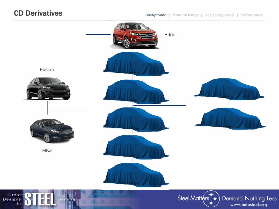
CD Derivatives Background | Material Usage | Design Approach | Performance
Fusion
MKZ
Edge
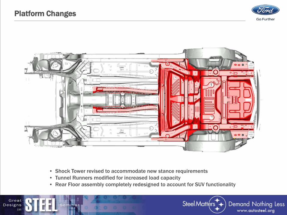
Platform Changes
• Shock Tower revised to accommodate new stance requirements • Tunnel Runners modified for increased load capacity • Rear Floor assembly completely redesigned to account for SUV functionality
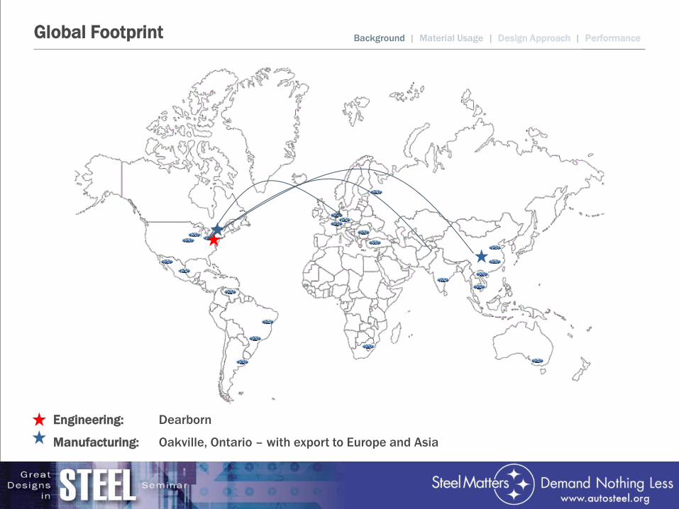
Global Footprint
Engineering: Dearborn
Manufacturing: Oakville, Ontario – with export to Europe and Asia
Background | Material Usage | Design Approach | Performance
MATERIAL USAGE
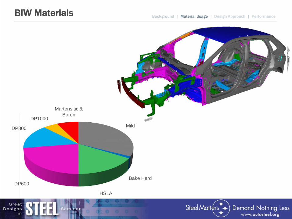
BIW Materials Background | Material Usage | Design Approach | Performance
Martensitic & Boron
Mild
Bake Hard
HSLA
DP600
DP800
DP1000
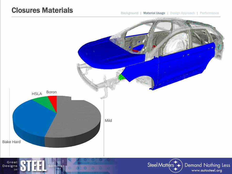
Closures Materials
Mild
Bake Hard
HSLA Boron
Background | Material Usage | Design Approach | Performance
DESIGN APPROACH
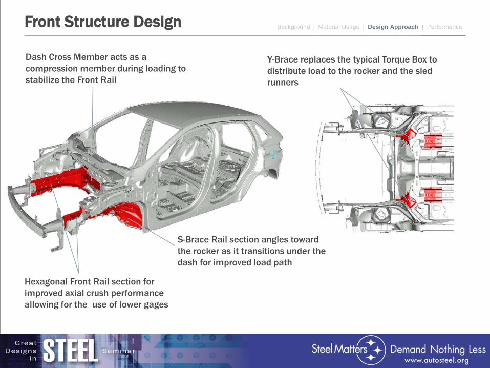
Front Structure Design Background | Material Usage | Design Approach | Performance
Hexagonal Front Rail section for improved axial crush performance allowing for the use of lower gages
Dash Cross Member acts as a compression member during loading to stabilize the Front Rail
S-Brace Rail section angles toward the rocker as it transitions under the dash for improved load path
Y-Brace replaces the typical Torque Box to distribute load to the rocker and the sled runners
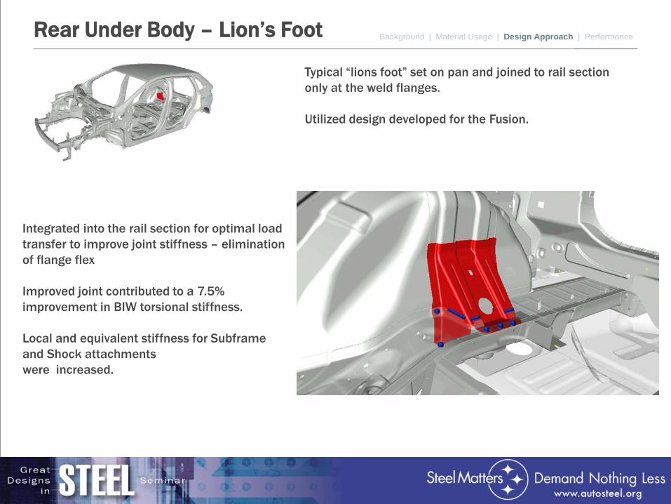
Rear Under Body – Lion’s Foot
Typical “lions foot” set on pan and joined to rail section only at the weld flanges. Utilized design developed for the Fusion.
Background | Material Usage | Design Approach | Performance
Integrated into the rail section for optimal load transfer to improve joint stiffness – elimination of flange flex Improved joint contributed to a 7.5% improvement in BIW torsional stiffness. Local and equivalent stiffness for Subframe and Shock attachments were increased.
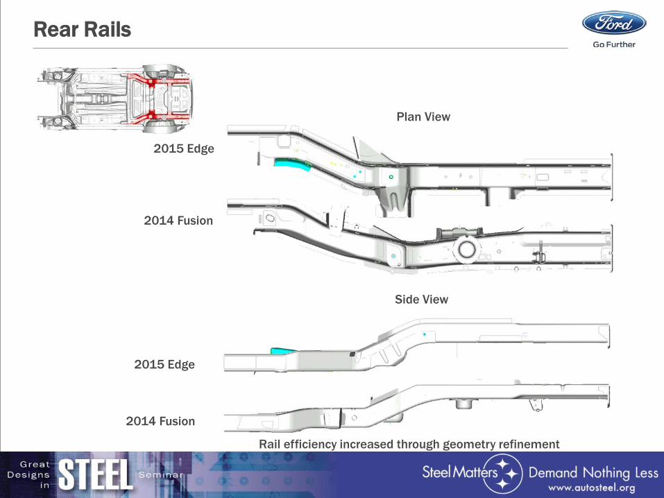
Rear Rails
Rail efficiency increased through geometry refinement
Plan View
Side View
2015 Edge
2015 Edge
2014 Fusion
2014 Fusion
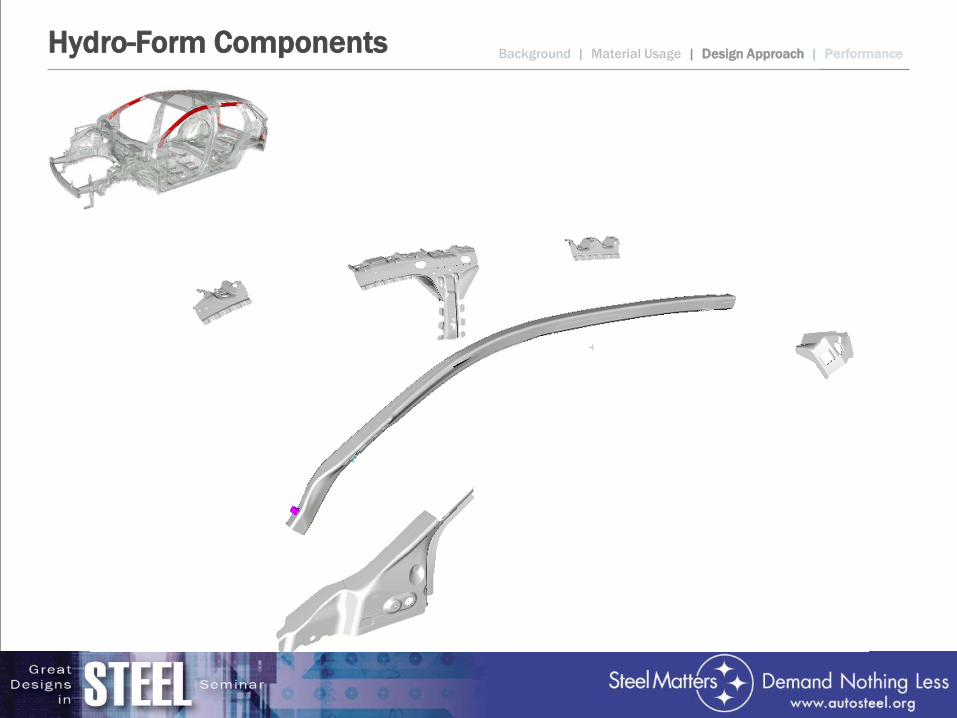
Hydro-Form Components Background | Material Usage | Design Approach | Performance
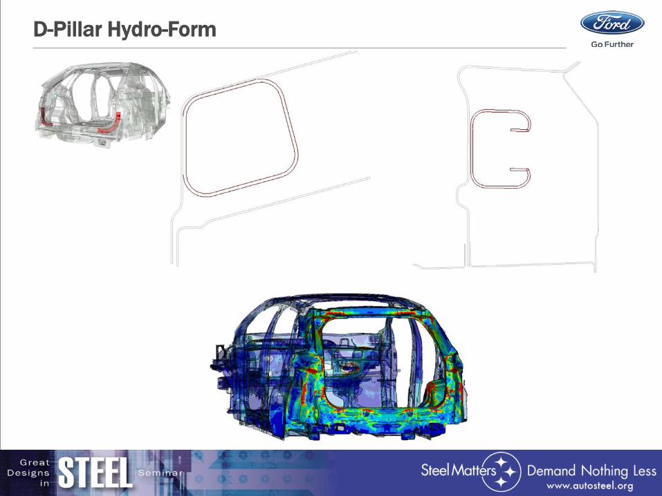
D-Pillar Hydro-Form
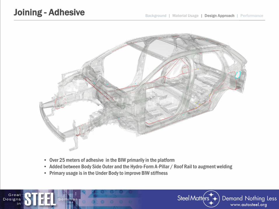
Joining - Adhesive
• Over 25 meters of adhesive in the BIW primarily in the platform • Added between Body Side Outer and the Hydro-Form A-Pillar / Roof Rail to augment welding • Primary usage is in the Under Body to improve BIW stiffness
Background | Material Usage | Design Approach | Performance
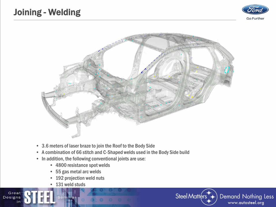
Joining - Welding
• 3.6 meters of laser braze to join the Roof to the Body Side • A combination of 66 stitch and C-Shaped welds used in the Body Side build • In addition, the following conventional joints are use:
• 4800 resistance spot welds • 55 gas metal arc welds • 192 projection weld nuts • 131 weld studs
FUNCTIONAL PERFORMANCE
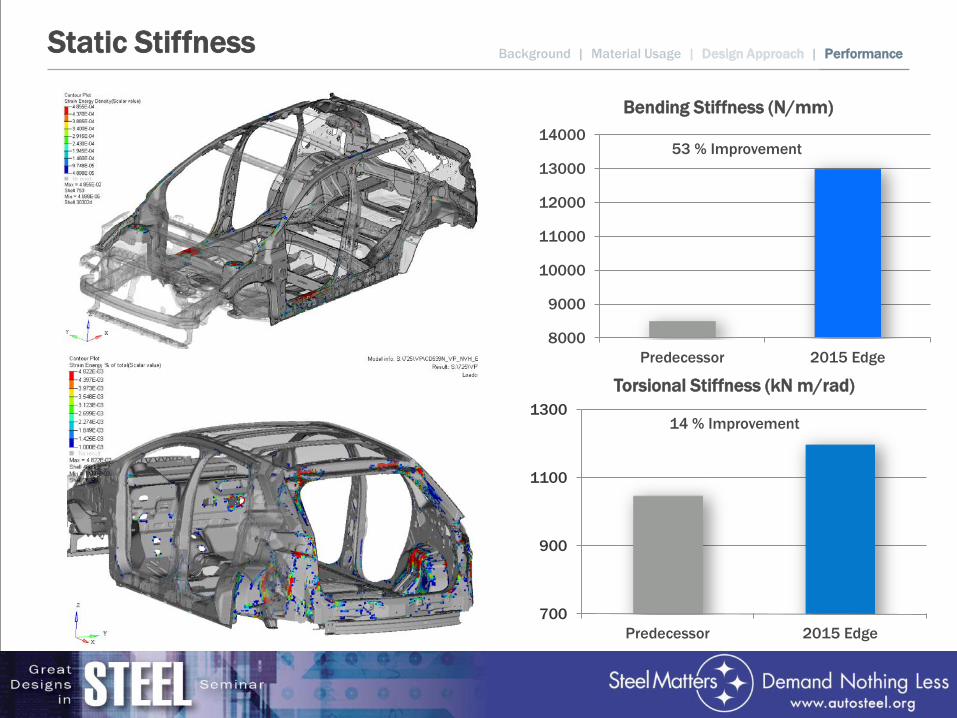
Static Stiffness
700
900
1100
1300
Predecessor 2015 Edge
8000
9000
10000
11000
12000
13000
14000
Predecessor 2015 Edge
Bending Stiffness (N/mm)
Torsional Stiffness (kN m/rad)
53 % Improvement
14 % Improvement
Background | Material Usage | Design Approach | Performance
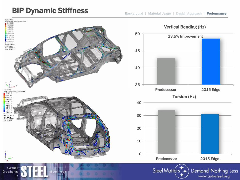
BIP Dynamic Stiffness
0
10
20
30
40
Predecessor 2015 Edge
35
40
45
50
Predecessor 2015 Edge
Vertical Bending (Hz)
Torsion (Hz)
13.5% Improvement
Background | Material Usage | Design Approach | Performance
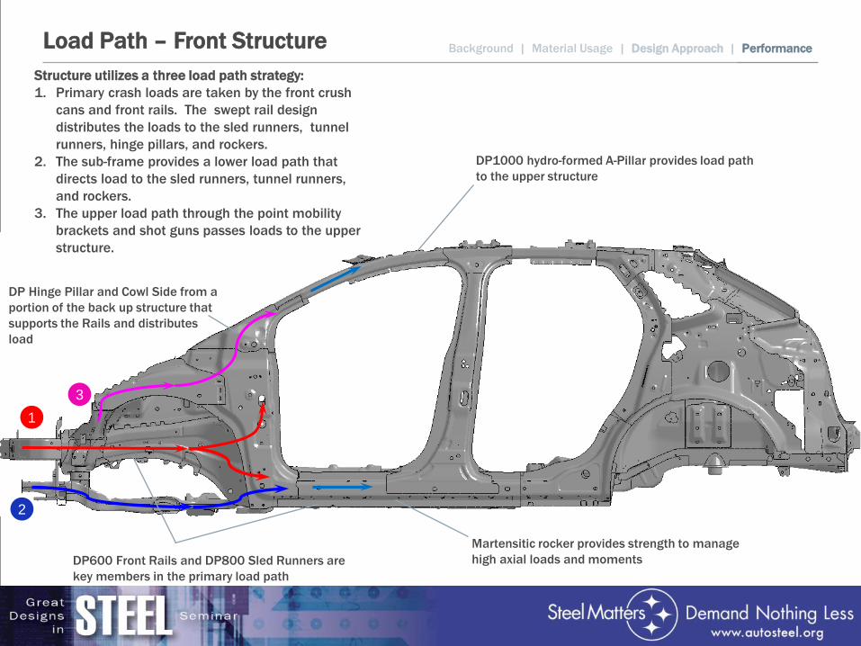
Load Path – Front Structure Background | Material Usage | Design Approach | Performance
DP Hinge Pillar and Cowl Side from a portion of the back up structure that supports the Rails and distributes load
Martensitic rocker provides strength to manage high axial loads and moments
DP1000 hydro-formed A-Pillar provides load path to the upper structure
Structure utilizes a three load path strategy: 1. Primary crash loads are taken by the front crush
cans and front rails. The swept rail design distributes the loads to the sled runners, tunnel runners, hinge pillars, and rockers.
2. The sub-frame provides a lower load path that directs load to the sled runners, tunnel runners, and rockers.
3. The upper load path through the point mobility brackets and shot guns passes loads to the upper structure.
1 3
2
DP600 Front Rails and DP800 Sled Runners are key members in the primary load path
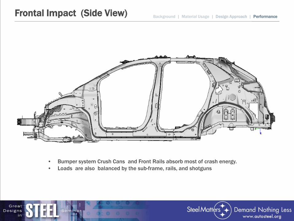
Frontal Impact (Side View)
• Bumper system Crush Cans and Front Rails absorb most of crash energy. • Loads are also balanced by the sub-frame, rails, and shotguns
Background | Material Usage | Design Approach | Performance
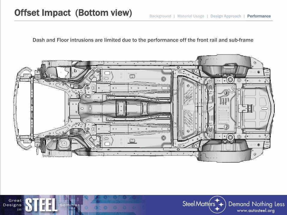
Offset Impact (Bottom view)
24
Dash and Floor intrusions are limited due to the performance off the front rail and sub-frame
Background | Material Usage | Design Approach | Performance
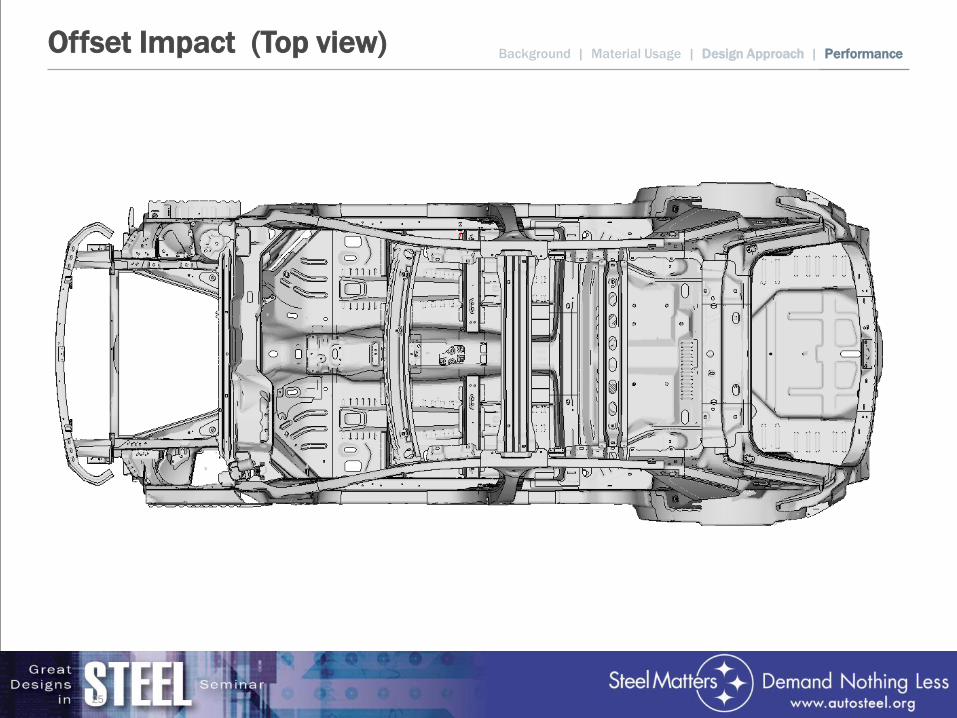
Offset Impact (Top view)
25
Background | Material Usage | Design Approach | Performance
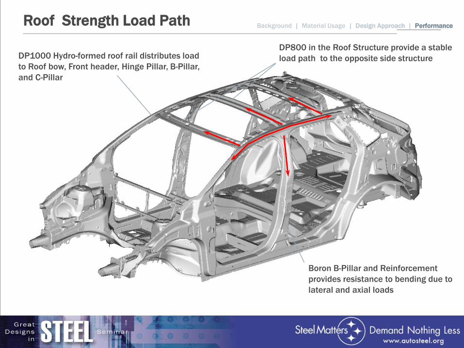
Roof Strength Load Path Background | Material Usage | Design Approach | Performance
DP1000 Hydro-formed roof rail distributes load to Roof bow, Front header, Hinge Pillar, B-Pillar, and C-Pillar
Boron B-Pillar and Reinforcement provides resistance to bending due to lateral and axial loads
DP800 in the Roof Structure provide a stable load path to the opposite side structure
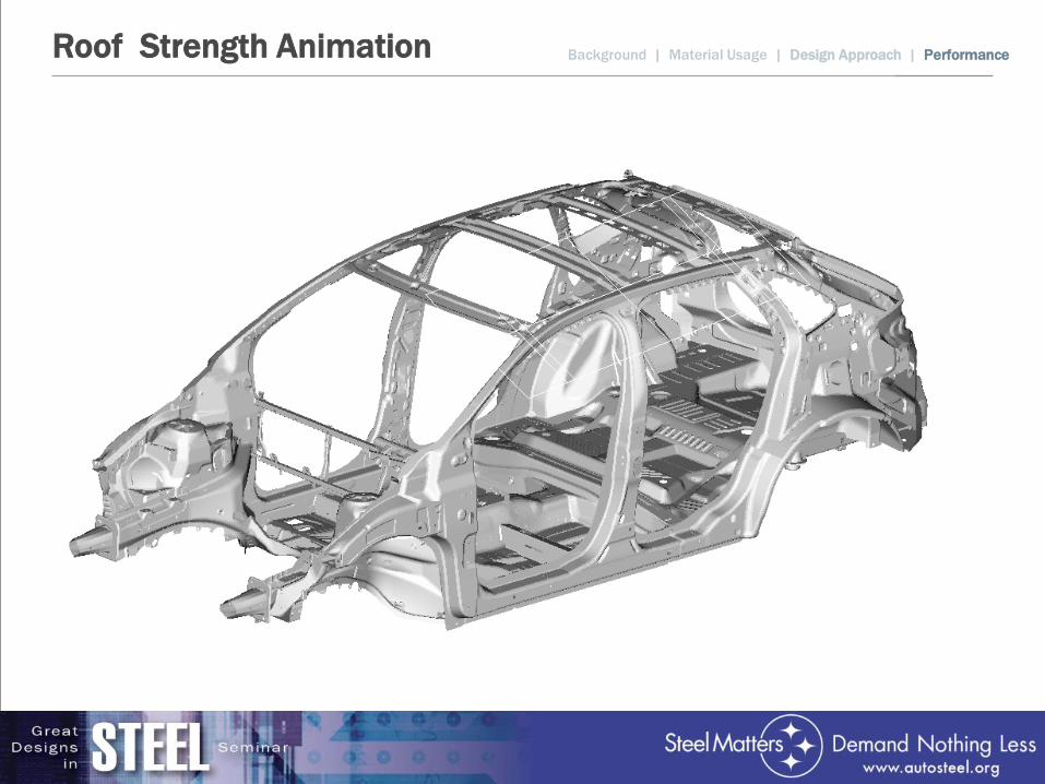
Roof Strength Animation Background | Material Usage | Design Approach | Performance
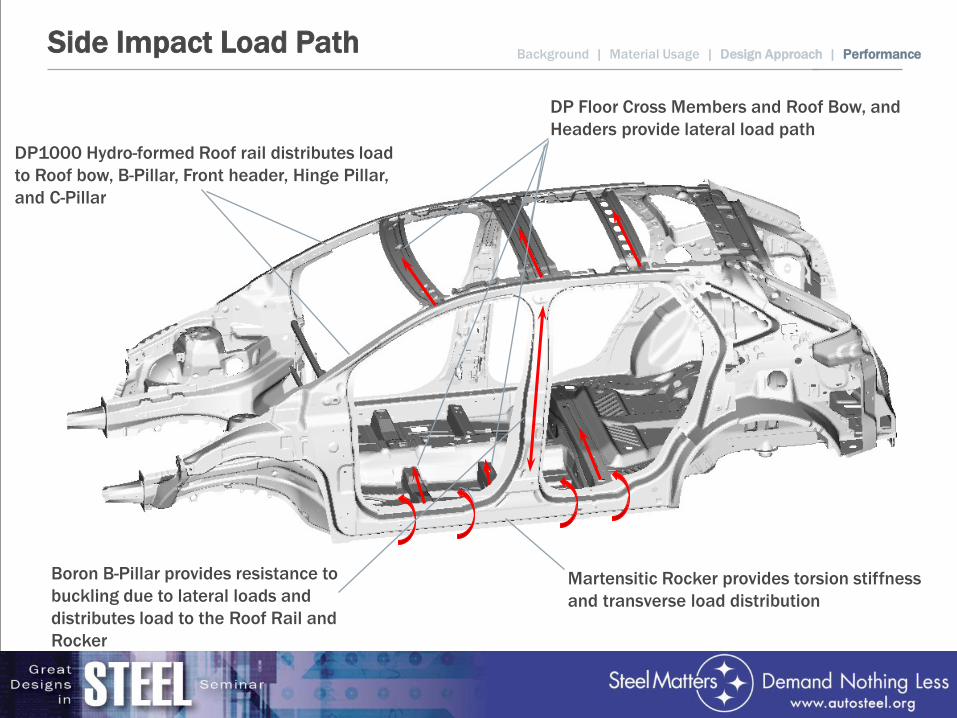
Side Impact Load Path Background | Material Usage | Design Approach | Performance
Martensitic Rocker provides torsion stiffness and transverse load distribution
Boron B-Pillar provides resistance to buckling due to lateral loads and distributes load to the Roof Rail and Rocker
DP Floor Cross Members and Roof Bow, and Headers provide lateral load path
DP1000 Hydro-formed Roof rail distributes load to Roof bow, B-Pillar, Front header, Hinge Pillar, and C-Pillar
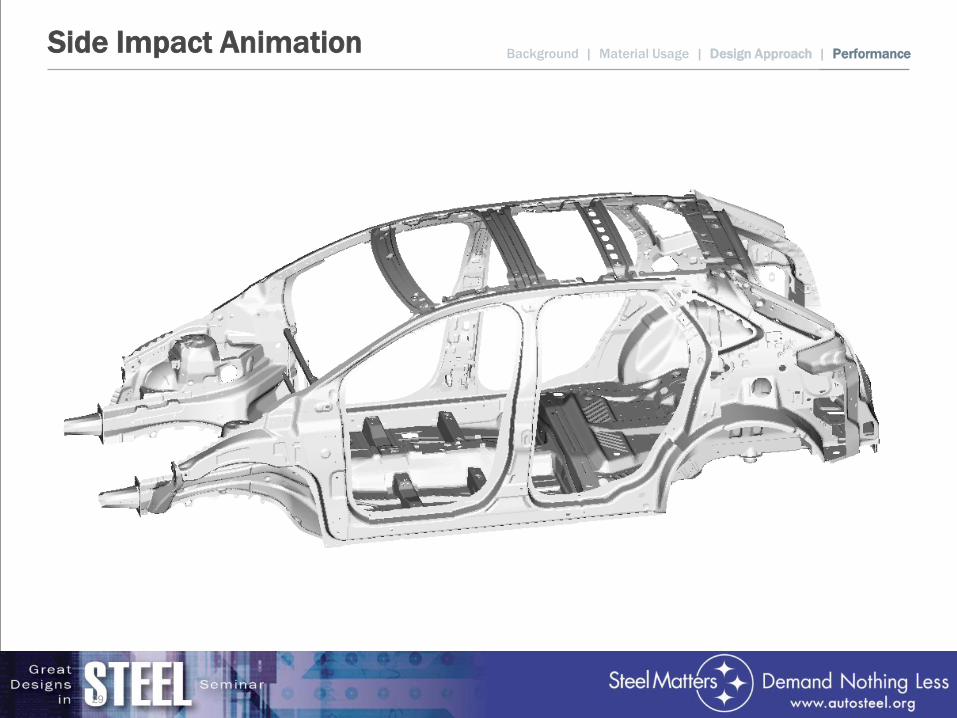
Side Impact Animation
29
Background | Material Usage | Design Approach | Performance
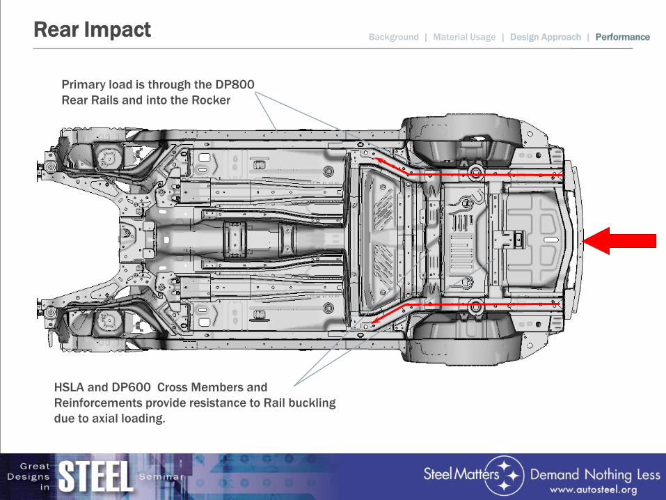
Rear Impact Background | Material Usage | Design Approach | Performance
Primary load is through the DP800 Rear Rails and into the Rocker
HSLA and DP600 Cross Members and Reinforcements provide resistance to Rail buckling due to axial loading.
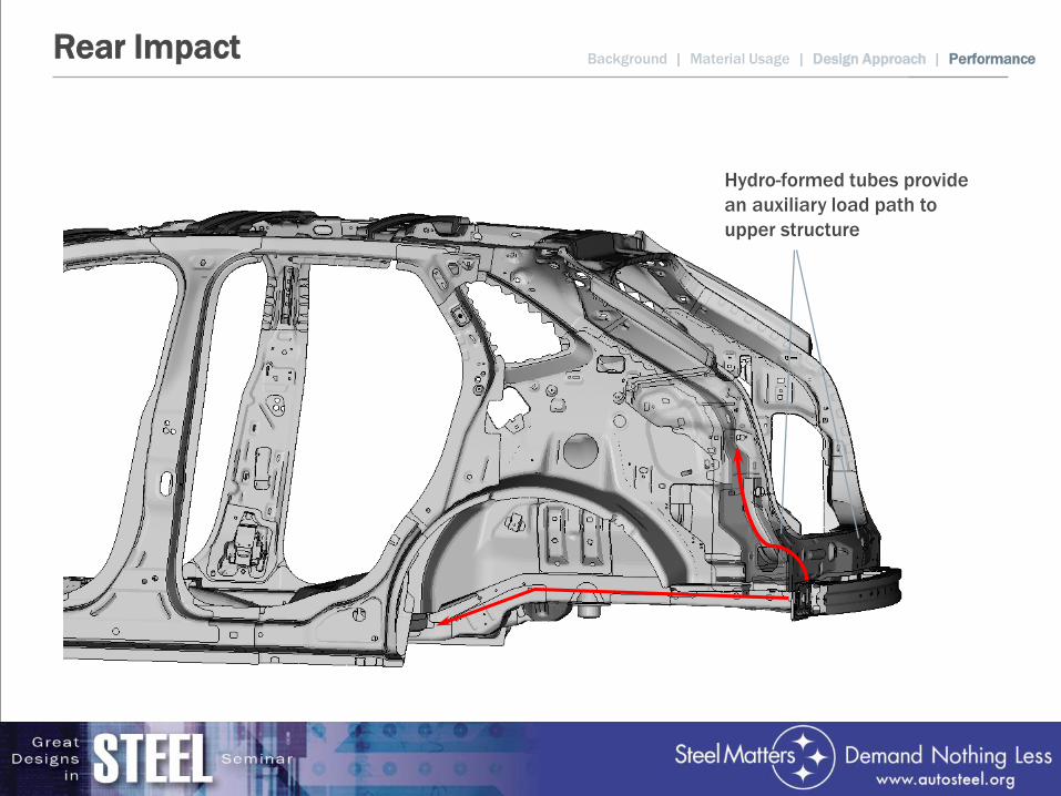
Rear Impact Background | Material Usage | Design Approach | Performance
Hydro-formed tubes provide an auxiliary load path to upper structure
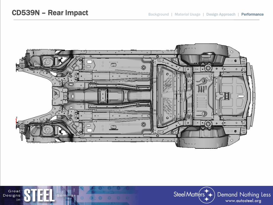
Background | Material Usage | Design Approach | Performance CD539N – Rear Impact
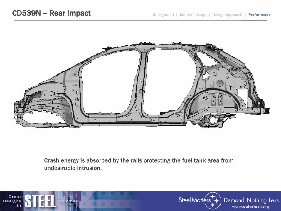
Background | Material Usage | Design Approach | Performance CD539N – Rear Impact
Crash energy is absorbed by the rails protecting the fuel tank area from undesirable intrusion.

Thank You for Your Attention

Presentations will be available May 18 at www.autosteel.org
Great Designs in Steel is Sponsored by: