Embed Size (px)
Citation preview

ADVANCED LAND OBSERVATION SATELLITE - ALOS
The Advanced Land Observing Satellite (ALOS) developed by the Japan Aerospace Exploration Agency (JAXA) was successfully launched on January 24, 2006. The satellite has three sensors i.e., two optical imagers(PRISM and AVNIR-2) and an L-band Synthetic Aperture (PALSAR). The mission objectives of ALOS include cartography, regional observation, and disaster monitoring. It has been designed to have a short revisit capability such that in cases of natural disasters, ALOS will be able to capture images of the disaster area with AVNIR-2 or PALSAR within a few days.
GEOIMAGE has been appointed as a Commercial Distributor of ALOS imagery and authorised to sell Standard and Value-Added Products to clients in Oceania (Australia, New Zealand, PNG and Pacific Islands), and Value-Added Products to clients throughout the world.
Data Availability and ApplicationsThe stereo PRISM data allows excellent quality high resolution DEMs to be developed over large areas at relatively low cost (See page 16). Merging or pan-sharpening the nadir PRISM data with AVNIR-2 imagery creates 2.5m high resolution multispectral datasets including natural colour imagery.
The Standard Data Products are in CEOS format and include-
GEOIMAGE recommends the Level 1B2R where orthorectification of the data is required and level 1B2G (purchased as a TIF file) if only systematic rectification is required.The ALOS mission features a systematic observation strategy which comprises pre-launch, systematic global observation plans for all three instruments. The strategy is implemented as a top-level foreground mission and with a priority level second only to that of emergency observations. Copies of these observation plans for PRISM and AVNIR-2 are available athttp://www.eorc.jaxa.jp/ALOS/obs/alos_scenario/avnir-2/avnir-2.htmhttp://www.eorc.jaxa.jp/ALOS/obs/alos_scenario/prism/prism.htmACRES is the Oceania Data Node for ALOS and as well as having a reception and archiving role, will be distributing ALOS data to non-commercial customers. Customers wishing to purchase ALOS data from ACRES will first need to register their proposed use with ACRES so that they can validate and approve the use as non-commercial.
PRISMThe Panchromatic Remote-sensing Instrument for Stereo Mapping (PRISM) is a panchromatic radiometer with 2.5-metre spatial resolution. The instrument has three independent optical systems for nadir, forward and backward looking to achieve along-track stereoscopy. Forward and backward telescopes are inclined + and - 24 degrees from nadir to realize a base-to-height ratio of 1.0. It is expected that the PRISM instrument will be capable of producing DEMs with errors of about 5m and with a 10m grid spacing.
PRISM data is collected in one of 9 possible Observation Modes - of which Mode 1 - Triplet observation mode with 35km wide simultaneous forward, nadir and backward views is expected to be the main one. This means that 2 cycles of capture of 46 day each are required to get complete PRISM coverage of any area. Mode 3 which produced 70km wide nadir PRISM imagery (corresponding to an AVNIR-2 nadir scene) is not expected to be a significant mode of operation.
AVNIR-2The Advanced Visible and Near Infrared Radiometer type 2 (AVNIR-2) is a visible and near infrared radiometer for observing land and coastal zones and provides better spatial land coverage maps and land-use classification maps for monitoring regional environment. The AVNIR-2 is a successor to the AVNIR onboard the Advanced Earth Observing Satellite (ADEOS) launched in August 1996. Its main improvement over AVNIR-1 is its instantaneous field-of-view (IFOV). The AVNIR-2 provides 10m spatial resolution images compared with the 16m resolution of AVNIR-1. The higher resolution was realized by improving the CCD detectors (AVNIR: 5,000 pixels per CCD, AVNIR-2: 7,000 pixels per CCD) and their electronics. Another improvement is a cross track pointing function for prompt observation of disaster areas. The off-nadir pointing angle of AVNIR-2 is + and - 44deg.
For more technical details on the ALOS imagery, including PALSAR, please see page 36 of the GEOIMAGE 2005 Brochure.
PRISM CharacteristicsNumber of Bands 1 (Panchromatic)
Wavelength 0.52 - 0.77 micrometers
Number of Optics 3 (Nadir; Forward; Backward)
Base-to-Height ratio 1.0 (between Forward and Backward looking)
Spatial Resolution 2.5m
Swath Width 70km (Nadir only) /35km (Triplet mode)
S/N >70
MTF >0.2
Number of Detectors 28000 / band (Swath Width 70km) 14000 / band (Swath Width 35km)
Pointing Angle -1.5 to +1.5 deg. (Triplet Mode, Cross Track)
Bit Length 8 bits
AVNIR-2 CharacteristicsNumber of Bands 4
Wavelength Band 1 : 0.42 - 0.50 micrometersBand 2 : 0.52 - 0.60 micrometersBand 3 : 0.61 - 0.69 micrometersBand 4 : 0.76 - 0.89 micrometers
Spatial Resolution 10m (at Nadir)
Swath Width 70km (at Nadir)
S/N >200
MTF Band 1~3 : >0.25Band 4 : >0.20
Number of Detectors 7000 / band
Pointing Angle -44 to +44 deg.
Bit Length 8 bits
Emergency response image of the Newcastle floods in June 2007. AVNIR-2 image collected on 10 June 2007. © JAXA 2007. A points to the stranded coal carrier the Pasha Bulker and B shows the interface between the brown flood waters and the normal ocean waters.
B
A
Orthorectified 70km by 70km 10m resolution AVNIR-2 image & superimposed 35 by 35km 2.5m resolution orthorectified nadir PRISM image over Sydney collected on 21st January 2007. © JAXA(2007) DISTRIBUTED BY RESTEC
Greyscale ALOS PRISM at 1:15k scale Sydney area. © JAXA(2007) Distributed by RESTEC
PRISM/AVNIR-2
LEVEL 1aUncompressed, reconstructed digital counts, with radiometric calibration coefficients and geometrical correction coefficients which are appended but not applied.
1B1 Radiometrically calibrated data
1B2 Geometrically calibrated data
PALSAR
LEVEL 1.0Uncompressed, reconstructed signal data, with radiometric calibration coefficients and geometrical correction coefficients which are appended but not applied.
1.1Range and azimuth compressed Complex data on slant range
1.5 Multi-look processed images projected to map coordinates
12

HOW CAN GEOIMAGE HELP?> archive searches for data covering your area of interest
> acquire the data and orthorectify to your datum/projection
> DEM generation from triplet PRISM imagery
> pan-sharpening of the AVNIR-2 using PRISM data
> supply of digital data on DVD or for FTP download
> supply of normal or pseudo-stereo hardcopy prints.
ADVANCED LAND OBSERVATION SATELLITE - ALOS
Orthorectified 70km by 70km 10m resolution AVNIR-2 image & superimposed 35 by 35km 2.5m resolution orthorectified nadir PRISM image over Sydney collected on 21st January 2007. © JAXA(2007) DISTRIBUTED BY RESTEC
RADIOMETRIC AND GEOMETRICAL QUALITYThe AVNIR-2 data that we have seen to date is generally of very high quality although there has been one instance where striping was present both along path and cross path and a substitute scene had to be ordered. Some striping noise is evident in the PRISM imagery and its removal has been identified as a future goal for JAXA/RESTEC (See insert this page). Details of the geometric and radiometric accuracies of standard products as assessed by JAXA are detailed at http://www.eorc.jaxa.jp/hatoyama/satellite/data_tekyo_setsumei/alos_hyouka_e.html.
ADVANTAGES / DISADVANTAGES OF ALOS DATAData from the ALOS sensors has certain advantages over comparable satellite imagery including-
1. The low cost of the data compared to other similar resolution data,2. The presence of a Visible Blue band on the AVNIR-2 allowing the preparation of natural colour imagery,3. The triplet mode PRISM data has the capability to produce DEMs with a 10m cell size and high Z accuracies,4. The PRISM nadir imagery is captured as near as possible to vertical i.e. with minimal height offset and5. Quicklooks of new imagery are in the catalogue by the following day and there is rapid turnaround on orders.Disadvantages of the sensors are-
1. The PRISM images are quite noisy and there is some residual detector striping,
2. The nadir PRISM and nadir AVNIR-2 data are rarely captured simultaneously over the 70km swath width of the AVNIR-2 sensor although there is some 35km wide nadir PRISM imagery collected on the same overpass as vertical AVNIR-2 and
3. ALOS imagery is not captured on demand although this service may be introduced after the initial 3 year capture program which finishes in 2009.
Pan-sharpened natural colour ALOS AVNIR-2 at 1:15k scale Sydney area. © JAXA(2007) Distributed by RESTEC
PROBLEMS IN THE DATALike other very high resolution data, PRISM imagery has Blooming and Smear artifacts caused by highly reflective objects on the ground surface (Image A). The Blooming artifacts have a tail which is horizontal and this compares with a path orientated tail on similar artifacts in IKONOS and QuickBird imagery.
The PRISM imagery also suffers from artifacts that can best be described as “boxed noise” (Image B) and are due to non-optimal on-board jpeg compression. These artifacts are generally most visible in areas of low texture. These problems are described athttp://www.eoc.jaxa.jp/satellite/data_tekyo_setsumei/alos_tyui/index_e.html
Pan-SharpeningPan-sharpening is the process of transforming a low spatial resolution multispectral image by fusing it with a coregistered panchromatic image. ALOS imagery lends itself to this technique where the 10m resolution AVNIR-2 imagery (B) is combined with the 2.5m resolution nadir PRISM image(A) to give a 2.5m colour image (C). Because of the normal acquision of triplet mode PRISM where the path of the imagery is only 35km wide and the 70km wide path of the AVNIR-2, two overpasses of PRISM data are required to achieve complete spatial coverage. Merging of the nadir PRISM imagery with AVNIR-2 data which has been captured at off-nadir angles should not be a problem as long as a high resolution DEM is available. 1:20k scale. ©JAXA(2007) DISTRIBUTED BY RESTEC
A B
C
A
B
13

Pan-sharpened enhanced natural colour QuickBird imagery at 1:5k scale Port Hedland Mangroves 06 May 2002. © DigitalGlobe 2002
A CASE STUDY OF THE USE OF ALOS IMAGERYIN MINERAL EXPLORATION, PAKISTANIntroductionLake Resources N.L. has been exploring for epithermal gold and porphyry copper-gold deposits in Pakistan since its inception in 1997. One of the main prospects is the Koh-i-Sultan prospect in the Chagai region in northwest Balochistan. The Koh-i-Sultan tenement covers the partially dissected remnants of a major Quaternary age compound andesitic stratovolcano. Extensive zones of advanced argillic alteration with sulphur, barite and silica deposits and stockwork-veined altered intrusives, are present. The area is prospective for high sulphidation epithermal gold and porphyry copper-gold deposits. Anomalous levels of gold and base metals are present in stream sediments associated with major alteration zones in the vicinity of the Nawah Caldera at the south-eastern end of the Koh-i-Sultan Complex. Rock chip sampling of altered areas returned significant gold values.
The ProblemGEOIMAGE had previously supplied Landsat 7 ETM+ imagery and ASTER spectral imagery and DEMs to Lake Resources as a base for regional exploration over the Koh-i-Sultan prospect. To aid the next phase of exploration of the Nawah Caldera, more detailed accurate base maps, including topographic contours, were required to plan drill access into the area and to map the obvious zones of surface alteration and brecciation. The highest priority area required to be covered was 11 by 11km surrounded by a 20 by 20km lower priority area.
The SolutionInitial thinking was that an IKONOS new stereo acquisition would be the ideal solution and this would provide 1m resolution pan-sharpened colour imagery and a high resolution DEM. It was found however that the area was located within a GeoEye regional ground station and the cost of the IKONOS imagery was greater than double the normal worldwide standard price. A search of the ALOS archive showed that a triplet of cloud free ALOS PRISM imagery, acquired on 17th August 2006, was available over the area and that cloud free vertical AVNIR-2 imagery had been collected on 2 October 2006. This would allow the preparation of 2.5m pan-sharpened imagery and a high resolution DEM. Note that although the AVNIR-2 and PRISM imagery were not collected on the same date, the area is not subject to any short term change (except perhaps snow and cloud) and because the imagery was collected with similar ephemeris, image merging would not be a problem.
The MethodologyThe standard triplet of back, nadir and forward PRISM imagery and a non-standard AVNIR-2 image (moved to the south to cover the PRISM data), were purchased at 1B2R processing level. The data was read into PCI OrthoEngine using the newly developed ALOS module.Accurate ground control was only available for the immediate area of the Nawah Caldera and so it was decided to systematically rectify the imagery using the Geocover 2000 Landsat Pan image for E and N control and the SRTM data for Z control and then to fine tune the final orthorectified imagery using the client supplied ground control.The AVNIR-2 data was orthorectified first and then the nadir PRISM scene was orthorectified using ground control automatically generated in the Geomatica AUTOGCP module. The orthorectified AVNIR-2 and nadir PRISM data were then pan-sharpened using the Geomatica PANSHARP module.
DEM GenerationGround control for the back and forward PRISM images was taken from the orthorectified nadir PRISM imagery and the same points were also identified on the raw nadir image. Independent of the source of the stereo pairs, PCI OrthoEngine’s methodology for creating the DEM is similar and is described in detail by Toutin - http://www.ipi.uni-hannover.de/html/publikationen/2005/workshop/032-toutin.pdf. The method involves selection of several accurate GCPs in the stereo pairs, computation of a 3-D stereo model based on the sensor parameters and refined using the GCPs, processing of epipolar images in which the height parallax is maximised in the X direction, autocorrelation between the epipolar pairs on a pixel by pixel basis and computation of XYZ cartographic coordinates from the elevation parallaxes in a regular grid spacing.
DEM generation was carried out using epipolar images that were produced at 5m resolution to minimise the effect of noise in the PRISM data. With three obvious stereo images, there are three possibilities for epipolar pairs and a combination of pairs was found to produce a 10m DEM with almost perfect correlation and a low level of noise spikes. This grid was run through the Geomatica DWCON program which prepares the data for hydrological analysis and in particular fills small isolated depressions and produces a flow accumulation image which was used to automatically generate vector drainage lines. The infilled grid was used to generate 10m vector contours.
The extracted DEM is a surface model that normally includes the height of manmade features such as vegetation and buildings. This is not a problem in this area but will be a problem in areas of cultural disturbance and vegetation of variable heights.
The accuracy of the final grid is impossible to accertain because of the lack of ground control. Based on the local detail of the grid, the automatically generated drainage lines and theoretical considerations related to the size of the pixel, the local noise is believed to be of the order of 3-4metres.
Acknowledgements GEOIMAGE would like to thank Jim Clavarino of Lake Resources N.L. for permission to write up this case study. All the ALOS images are Copyright JAXA(2006) and distributed by RESTEC.
Pan-sharpened natural colour ALOS AVNIR-2 at 1:25k scale Pakistan. © JAXA(2007) Distributed by RESTEC
Final orthorectified AVNIR-2 natural colour image and superimposed greyscale nadir PRISM image.
© JAXA 2006
Comparison of the 10m ALOS generated DEM (left) and the SRTM DEM (right) over the Nawah Caldera.
Pseudocoloured ALOS DEM for the PRISM pair at a 10m cell size. The elevations range from 770m to 2320m. Box shows location of enlargements below.
14
IN MINERAL EXPLORATION, PAKISTAN
Left image: Natural colour pan-sharpened ALOS imagery at 1:25k scale with drainage lines automatically generated from the 10m DEM. Right image: Pseudocoloured ALOS 10m DEM with 20m black contours and red drainage lines automatically generated from the DEM
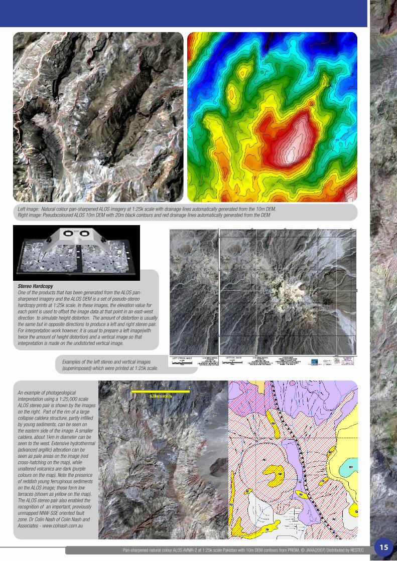
Stereo HardcopyOne of the products that has been generated from the ALOS pan-sharpened imagery and the ALOS DEM is a set of pseudo-stereo hardcopy prints at 1:25k scale. In these images, the elevation value for each point is used to offset the image data at that point in an east-west direction to simulate height distortion. The amount of distortion is usually the same but in opposite directions to produce a left and right stereo pair. For interpretation work however, it is usual to prepare a left image(with twice the amount of height distortion) and a vertical image so that interpretation is made on the undistorted vertical image.
An example of photogeological interpretation using a 1:25,000 scale ALOS stereo pair is shown by the images on the right. Part of the rim of a large collapse caldera structure, partly infilled by young sediments, can be seen on the eastern side of the image. A smaller caldera, about 1km in diameter can be seen to the west. Extensive hydrothermal (advanced argillic) alteration can be seen as pale areas on the image (red cross-hatching on the map), while unaltered volcanics are dark (purple colours on the map). Note the presence of reddish young ferruginous sediments on the ALOS image; these form low terraces (shown as yellow on the map). The ALOS stereo pair also enabled the recognition of an important, previously unmapped NNW-SSE oriented fault zone. Dr Colin Nash of Colin Nash and Associates - www.colnash.com.au
Examples of the left stereo and vertical images (superimposed) which were printed at 1:25k scale.
Pan-sharpened natural colour ALOS AVNIR-2 at 1:25k scale Pakistan with 10m DEM contours from PRISM. © JAXA(2007) Distributed by RESTEC 15

DEM FROM ALOS PRISM DATA
One of the aims of the ALOS PRISM program was to produce DEMs (Digital Elevation Models) with less than 5 metre errors and with 10 metre grid spacing in support of the creation and updating of maps at a scale of 1:25,000. Software vendors in the photogrammetric sector have been slow to develop modules to process ALOS optical data because many rely on the availability of rational functions to define the “camera model”. The rational functions have only been released for PRISM Level 1B1 data where the data is still in separate CCD format. This is not the case for PCI Geomatics OrthoEngine which uses Toutin’s satellite model and which can process PRISM level 1B1 and 1B2R data. This software processes the PRISM triplet as separate epipolar pairs and has been used to produce the DEMs discussed here.
GEOIMAGE’s DEM generation procedure can be summarised as follows.
> orthorectify the nadir PRISM image using the best available ground control and available DEM. The use of the SRTM DEM here is not a problem because of the near vertical aspect of the nadir image.
> Select control points on the back/nadir/forward raw images based on the orthorectified nadir image. Only points that can be identified on all three images are used and obviously the more accurate the location of the points the better the model.
> Epipolar images for each image pair are generated at 5m pixel spacing.> Epipolar DEMS are generated at either a 5m or 10m spacing.> If there is low level systematic noise in the DEMs resulting from poor control of the
model this is best corrected at this stage before the geocoding of the DEMs.> The epipolar DEMs are geocoded and the final dem reading at any point on
the grid may be either based on an average of the individual DEMs or based on the correlations score during the epipolar DEM generation.
> The final DEM is edited for artifacts in water, cloud and shadow areas or for spikes.
GEOIMAGE recently conducted a test DEM generation from a PRISM triplet over Sydney to assess the accuracy of the DEM. The image used was collected on 21 January 2007 and was cloud free. The NSW Government’s PANRIIE SPOT 5 imagery was used for X and Y control and the NSW LANDS 25m DTM was used for Z control. The ALOS DEM was generated at 5m cell size from an average of the back/nadir and nadir/
forward DEMs. The ALOS DEM is a Digital Surface Model and includes the tops of buildings and vegetation as shown in the images at the bottom of this page. The comparison of approximately 1000 points between the NSW LANDS DTM and the ALOS DEM showed a mean difference of 3.7m and an RMS error of 5m.
This error is in the same range as determined by K. Wolff, A. Gruen, ETH Zurich: DSM Generation from Early ALOS/PRISM Data using SAT-PP and Junichi Takaku,et al.,High Resolution DSM Generation from ALOS PRISM.
Many of GEOIMAGE’s client are working in relatively isolated areas where good control is difficult to obtain and where the SRTM is the best DEM available. In such areas, where we have used the SRTM for the Z control, it has been necessary to do a considerable amount of massaging to take out high frequency noise but believe the final DSM result is accurate to about 5m relative.
Three image views of an area along Spit Rd, Spit Junction, Sydney showing the detail in the dem at a scale of approximately 1:10 000. Image A: Anaglyph presentation of the back and forward PRISM images that have been orthorectified using the NSW LANDS DTM. Red and green fringes indicate features that differ in height from the ground. Image B: Pseudocoloured ALOS 5m DEM. There is an elevation difference within the area of 2m to 95m and the large white high area in the centre is 23m above ground level. The DEM generation was unable to separate the heights of the three white buildings that can be seen in Image C. Image C: Pan-sharpened natural colour ALOS image.
3m coloured contours derived from an ALOS PRISM pair on a natural colour IKONOS (© GeoEye 2005) image. The SRTM DEM was used for the Z control in this example. Approximate scale 1:20k.
Plot of NSW LANDS DTM vs ALOS DEM
Pan-sharpened natural colour ALOS AVNIR-2 at 1:25k scale Sydney area with 3m DEM contours from PRISM. © JAXA(2007) Distributed by RESTEC
A B C
16