Embed Size (px)
Citation preview

ADVANCED SOFTWARE SOLUTIONS
HumanMachine
Interfaces
SubstationAutomation
DistributionAutomation
EnhancedSCADA
Communications

At GE Energy Services, our mission is to champion our
customers’ success in today’s dynamic energy marketplace
by providing smart solutions to optimize transmission and
distribution operations.
We team up with utilities worldwide to carry out the new
mandates for delivering reliable and quality power using
real-time information technology specifically developed
for electric power applications. Through innovative
substation systems and specialized engineering services –
from portable test instruments to turnkey automation
solutions – GE Energy Services helps utilities safely and
efficiently automate, monitor and maintain critical
transmission and distribution assets.

BE IN THE KNOWFrom our ever-growing library of automation, supervisory control and data acquisition, and communicationssoftware, GE Energy Services can tailor solutions to integrate functions within your transmission and distributionsystem to meet your unique monitoring and control needs. You’ll know what is happening at every point on yournetwork and be able to act quickly to keep everything running smoothly.
Demand efficiency at every level of your system Electrical utilities are just as cost-conscious as any other corporation today. Increased competition, decreasedmargins and regulatory changes demand efficiency at every level of the business. Enhance your system withone or more of these automation applications and you can integrate functions that will result in lowerinstallation, operations and maintenance, and capital costs of your transmission and distribution system.
For example, you can:1. Save thousands of dollars on pricey standalone devices by taking advantage of integrated system
functions that eliminate redundant and space-consuming equipment. That means only one set ofhardware, one set of wiring, one communications system and one system to commission,operate and maintain.
2. Eliminate site visits and cut operations and maintenance costs by remotely accessing andprogramming devices from a central station.
3. Extend primary equipment life by collecting accurate and relevant operating data for just-in-timemaintenance.
4. Cut engineering and planning costs by sharing pre-processed data and analytical reports company-wide with standardized file formats and common databases.
Benefits your customers will appreciate!• Improve the quality of service with enhanced system reliability and safety.• Reduce the frequency of outages by identifying problems before equipment fails.• Restore service faster by pinpointing faults and improving response times with better alarms,
indications and diagnostics.
HUMAN MACHINE INTERFACESPowerLink Advantage Graphical User InterfaceThe enhanced performance and usability of PowerLink Advantage differentiates this graphical user interface fromother generic offerings. Its features address the specific demands of electrical utility substation automationapplications, such as full SCADA functionality, industry standard communications, advanced alarm managementand a redundancy option; as well as database connectivity, extended system security and user-friendlyconfiguration tools.
PowerLink Advantage is a powerful and flexible tool that gives operators detailed and timely supervision andcontrol of all substation equipment, including intelligent electronic devices, with clear graphical, alarm anddynamic text displays, plus power quality and digital fault event data. The historical and real-time databases areexcellent resources for analyzing events and generating reports critical to making more informed operating andbusiness decisions. With this impressive list of capabilities, you can avoid the typically required but bulky andcostly mimic panels and dedicated chart recorders used in substation installations.
Custom applications tomeet diverse needsWhether you are a large
investor-owned corporation
or a small municipal utility,
GE software experts have the
real-time programming and
advanced, custom software
design experience to build
applications that meet your
unique electrical system
operating requirements.
With all our software
applications we aim to
improve system performance
while reducing costs. We
also design applications to be
flexible and reusable. You
can later fine-tune the
software for use throughout
your utility’s system.
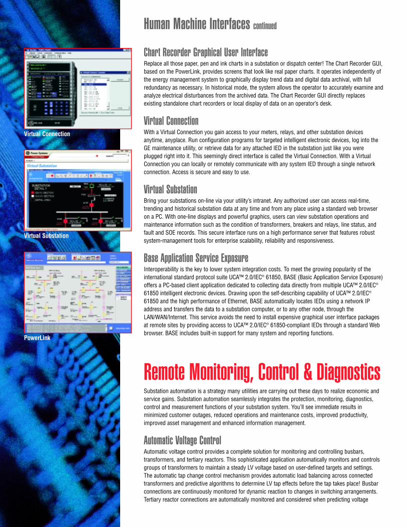
Chart Recorder Graphical User InterfaceReplace all those paper, pen and ink charts in a substation or dispatch center! The Chart Recorder GUI,based on the PowerLink, provides screens that look like real paper charts. It operates independently ofthe energy management system to graphically display trend data and digital data archival, with fullredundancy as necessary. In historical mode, the system allows the operator to accurately examine andanalyze electrical disturbances from the archived data. The Chart Recorder GUI directly replacesexisting standalone chart recorders or local display of data on an operator’s desk.
Virtual ConnectionWith a Virtual Connection you gain access to your meters, relays, and other substation devicesanytime, anyplace. Run configuration programs for targeted intelligent electronic devices, log into theGE maintenance utility, or retrieve data for any attached IED in the substation just like you wereplugged right into it. This seemingly direct interface is called the Virtual Connection. With a VirtualConnection you can locally or remotely communicate with any system IED through a single networkconnection. Access is secure and easy to use.
Virtual SubstationBring your substations on-line via your utility’s intranet. Any authorized user can access real-time,trending and historical substation data at any time and from any place using a standard web browseron a PC. With one-line displays and powerful graphics, users can view substation operations andmaintenance information such as the condition of transformers, breakers and relays, line status, andfault and SOE records. This secure interface runs on a high performance server that features robustsystem-management tools for enterprise scalability, reliability and responsiveness.
Base Application Service ExposureInteroperability is the key to lower system integration costs. To meet the growing popularity of theinternational standard protocol suite UCA™ 2.0/IEC® 61850, BASE (Basic Application Service Exposure)offers a PC-based client application dedicated to collecting data directly from multiple UCA™ 2.0/IEC®
61850 intelligent electronic devices. Drawing upon the self-describing capability of UCA™ 2.0/IEC®
61850 and the high performance of Ethernet, BASE automatically locates IEDs using a network IPaddress and transfers the data to a substation computer, or to any other node, through theLAN/WAN/Internet. This service avoids the need to install expensive graphical user interface packagesat remote sites by providing access to UCA™ 2.0/IEC® 61850-compliant IEDs through a standard Webbrowser. BASE includes built-in support for many system and reporting functions.
Remote Monitoring, Control & DiagnosticsSubstation automation is a strategy many utilities are carrying out these days to realize economic andservice gains. Substation automation seamlessly integrates the protection, monitoring, diagnostics,control and measurement functions of your substation system. You’ll see immediate results inminimized customer outages, reduced operations and maintenance costs, improved productivity,improved asset management and enhanced information management.
Automatic Voltage ControlAutomatic voltage control provides a complete solution for monitoring and controlling busbars,transformers, and tertiary reactors. This sophisticated application automatically monitors and controlsgroups of transformers to maintain a steady LV voltage based on user-defined targets and settings.The automatic tap change control mechanism provides automatic load balancing across connectedtransformers and predictive algorithms to determine LV tap effects before the tap takes place! Busbarconnections are continuously monitored for dynamic reaction to changes in switching arrangements.Tertiary reactor connections are automatically monitored and considered when predicting voltage
Human Machine Interfaces continued
PowerLink
Virtual Connection
Virtual Substation

changes due to LV transformer tapping. Automatic control can be switched out remotely to allow manualtransformer control whenever needed.
CalculatorThis convenient soft logic utility can perform applications such as substation level interlocking, feederinterlocking, and converting digital inputs to control outputs for driving a map board. Program the system tocontrol analog inputs and outputs and digital inputs and outputs based on the result of configuredmathematical and logical expressions. Create expressions using a library of constants, operators andreferences to system database points, as well as comparison operators, logic operators, logic bit operators,math operators, sign operators and expression delimiters.
Digital Fault RecorderThe Digital Fault Recorder system based on the D25 and integrated Substation Control System is aneffective way to accurately record and analyze substation events while avoiding the excessive added costs ofstandalone digital fault recorders. This scalable system can accommodate virtually any number of analog ordigital channels by employing peer-to-peer communications to cross-trigger a set of D25s. This allows youto collect a full set of data on the condition of your network.
Through the PC-based DirectView and PowerLink workstation viewers, you can get a virtual snapshot ofthe system at the time of the fault and trace the incident with dexterity. You can clearly determine the order of events, and the performance and health of the breakers. The DirectView tool makes it easy for youto zoom in on and compare event records. With these capabilities as well as on-line configuration, uniquede-trigger functions and 240 cycles of storage, you no longer need to travel to the site to carry outpost-fault analysis.
Enhanced Load Shed ControlDuring an overload crisis situation, you can count on our Enhanced Load Shed Control program to maintainsystem operation within stable limits. The GE system can rapidly shed load at select locations by removingone or more feeders from service by disconnecting the feeder’s breakers. Once the system is stable again,the breaker can be closed by a command from the master station or by an operator through Wesmaint, orby some other special application.
Load and Dead Station TransferThe Load and Dead Station Transfer application works to maintain system efficiency by monitoring anetwork of substations and moving load off of overloaded transformers to other stations in the electricalnetwork as required. The application detects when a transformer reaches a predetermined overload setpoint, then transfers load to stations that have unused capacity. The application also automatically attemptsto restore power to feeders that lose their primary supply station. The operator can set the routine toconfirm switching operations prior to execution or to be in fully automatic mode. Load transfer is a provenway to postpone construction of new substations by reducing the overload on existing stations.
LogicLinx™Digital Fault Recording Power Quality Harmonics
“Our system employs the
Calculator application to
create and supply to our
EMS master a single
Trip/Close pseudo control
point for substation IEDs that
do not normally provide the
OPEN and CLOSE command
functionality paired into a
single point. By calculating
this single pseudo control
point, the EMS master can
control these IEDs in the
traditional manner,
eliminating the need for
costly and laborious
programming “work-arounds”
in the master, or firmware
revisions for either the master
or IEDs. The Calculator
provides the “quick fix” that
is an easy, cost-efficient, and
effective solution.”
Highline Electric Association,
Colorado, USA

LogicLinx™
LogicLinx™’s Windows® interface and IEC® 61131-3 standard are a welcomereprieve from other cumbersome and proprietary ladder logic programs.Begin creating programmable logic control sequences right away that areefficient and logical using a ready-to-use library of over 80 standardoperators, functions and function blocks. With a short lead time and low cost you can build and commission complex automation projects right fromyour desktop!
Several visual simulation tools allow you to test and troubleshoot yourprojects before downloading to the final GE automation platform. Discoverhow easily you can automate key station functions such as voltage control,delayed breaker reclosing, load tap changer control, auto source transfer andtransformer monitoring. No more writing code or installing costly hardwiredprogrammable logic controllers!
Power QualityPower Quality is becoming increasingly important to businesses that employautomated manufacturing processes or sensitive electronic loads. ThePower Quality system provides detailed power delivery and load monitoringand revenue metering information so operators can make the right decisionsto fulfill any Performance Guarantees you may have with your customers.The combination of the D25’s data collection capabilities, PowerLink’sautomatic retrieval and archive features, and the distributed nature of theintegrated Substation Control System LAN acts effectively to correct systemproblems, enhance system reliability and safety, and monitor the status of allstation primary equipment, protection and control devices.
The power quality system monitors:• Voltage and current symmetrical components• Harmonics up to and including 21st• Total harmonic distortion• Voltage sag, swell & interruptions • RMS profiling during a sag, swell or interruption• Metering and power factor• ITI curve superimposition.
With this information operators can diagnose power quality events withoutdispatching crews to investigate. RMS profiling data is supplied in theIEEE® Comtrade binary or ASCII file formats. Using PowerLink and the PQEvent Viewer you can monitor, review and analyze events for archiving andprinting reports. You will benefit from overall improved power quality ofyour transmission and distribution system.
Substation Load ReportingLet your GE system take over the function of conventional substationdemand meters and report load information on all banks and feeders within a substation. Acquire, process and store peak and off-peak demand data fortransfer to the master station including MVA peak, MW, MVARs, phase A, B,and C bus volts, and bus neutral amps.
Integrated Transformer MonitoringIntegrate transmission and distribution transformers with your SCADAsystem to give system operators and maintenance personnel real-time data
Remote Monitoring, Control continued
Transformer withLoad Tap Changer
“Hydro One Networks
(formerly known as Ontario
Hydro) has implemented
integrated programmable
logic control through
LogicLinx™ to carry out
transformer load tap changer
control and integrated
voltage reduction schemes
(with 3% and 5% options)
at several transmission
sites. At one of our hydro
generation sites we also
employ integrated PLC to
execute closed loop gate
control, generator set point
control, and gate position
control. These automation
schemes have allowed us to
realize strategic benefits of
improved reliability and
enhanced operational
efficiency.”
Hydro One Networks Inc.,
Ontario, Canada

and operational trends of transformers, load tap changers and breakers. By remotely monitoring primarysubstation equipment, system operators can be alerted to impending problems in order to avert, or at leastminimize, system outages, especially during periods of peak loads.
Avoid catastrophic equipment failures by monitoring the health of transformers, shunt reactors, currenttransformers and bushings for key variables such as load current, dissolved gases in oil, load tap changermonitoring, load tap changer control, moisture in oil, partial discharge, top oil temperature, ambient temperature,pressure of the inert air system, hottest spot calculation, cooling efficiency, and cooling control. Integratedtransformer monitoring contributes to enhanced system reliability and safety, operations and maintenancesavings, early warning of equipment failures, and optimized use of capital equipment.
DISTRIBUTION AUTOMATIONFeeder networks are direct lines to your customers! Whatever the cause, power outages frustrate and infuriatecustomers. Your quality of service affects their quality of life. Retain customer loyalty by keeping the lights on.
“A recent GE Energy Services analysis revealed that the fiscal justification of feederautomation can put $US1.9 million annually back into the utility’s pocket!”
Auto-SectionalizingAuto-sectionalizing is proven to reduce your outage frequency rate. The scheme works automatically to isolatefaults on distribution circuits and keep the lights on for as many customers as possible. When there is a load sidefault, the feeder IEDs, located at motor-operated switches up to ten miles apart along a distribution network, willimmediately detect and locate the over current, and automatically open the necessary sectionalizing switches toisolate the faulted section of the feeder, and try and correct the fault. Since this application resides on the feederIED, the auto-sectionalizing acts with or without communication with the master station, and it can beimplemented at new or existing switches. Utility field data demonstrates that auto-sectionalizing adds more thanfour months to Sustained Average Interruption Frequency Index (SAIFI) performance. This application is amigration path to our auto-restoration application which targets reduced outage duration.
ANNUALIZED ECONOMIC EVALUATION OF FEEDER AUTOMATION
$ 0
$ 400
$ 400
$ 800
$ 800
$ 1,200
$ 1,600
$ 2,000
thousands of $US
Annual O & M for feeder SCADA ($US178,080)
Penalties Averted ($US1,819,980)
Reduced O & M ($US1,272,000)
Fault Location Cost Reduction ($US42,750)
Energy Loss Reduction ($US11,910)
Deferred Investment ($US10,000)
Increased Revenues ($US8,433)
Feeder SCADA Capital Cost ($US984,741)
BENEFITSCOSTS
System and product specifications subject to change without notice. Typical benefits and cost reductions are estimates only.Actual results may vary depending on customer specific systems.
“We possessed an outdated,
proprietary distribution
automation system for the
Dallas-Fort Worth Airport
that was no longer
supported by the original
vendor or upgradeable to
current open protocols.
GE provided a new open-
technology system featuring
a Fault Localization scheme
that analyzes DFW Airport’s
complex distribution
network, and identifies
faults 60% faster than the
original system. The system
presents faults and network
interconnections to
dispatchers on graphical
user interface displays.”
TXU,
Texas, USA
Auto-RestorationIdeal for large commercial or industrial facilities that rely on a constant power supply, our auto-restoration scheme can reduce outages to less than a minute. This patented load transfer schemeautomatically locates and isolates faults on a feeder, qualifies the ability to restore load based onsubstation and feeder data then quickly restores power to unfaulted sections by supplying power fromanother source. System operators are kept informed of switch operations. Auto-restoration supportsmultiple seasons, modes of operation, circuit groups and complex feeder topologies.
Distribution Capacitor Bank ControlYou can gain an effective 1 MVAR of reactive support during peak loading periods on a givendistribution unit (transformer and feeders associated with that transformer) simply through the moreefficient use of already installed banks! Improve the control of your distribution capacitors bycoordinating capacitors based on the needs of the high side of the distribution substation transformer.As the power factor of the system is improved, the total current flow will be reduced and losses will bereduced. This permits additional load to be served by the same system. Holding the system closer tounity power factor also increases system stability. Typical payback for this system is less than twoyears! In addition, the system automatically alarms for blown fuses on capacitor banks saving manyutility worker-hours checking for blown fuses.
Fault Detection and AlarmingGE feeder IEDs integrate the functions of many traditional and relatively expensive devices such astransducers, fault detectors and indicators. By avoiding these discrete components in your distributionsystem design, you can drastically cut installation, commissioning and maintenance costs. All thewhile, the GE feeder IEDs provide reliable, full-time monitoring of distribution circuits and relevant faultinformation and alarms that allow you to quickly identify faults and minimize downtime. Specifically,detect both phase-to-phase and phase-to-ground faults, determine whether the protective deviceclearing the fault has successfully reclosed or locked out, and monitor the presence or absence ofvoltage and load current following a fault clearing operation.
Fault LocalizationLocate and isolate faults in seconds – not hours – and greatly reduce customer outage times! The FaultLocalization application is a fully configurable software package that provides fault detection, locationand graphical animation information within a GE system. In a typical system, the Fault Localizationapplication will query information retrieved from remote GE feeder IEDs concerning fault detection todetermine the state of a particular power distribution network. The application maintains an updatedstate of the entire distribution network; this allows the information to be accessed by a user through agraphical user interface to visually determine the condition of the distribution network.
Tri-Phase Unbalance DetectionMonitor voltage and current values from various field devices, such as RTUs or meters, based onprogrammable settings. Capabilities include detecting phase unbalance for voltage and current, andloss of phase for voltage and current, monitoring selective phase for voltage and current, andmeasuring specified time intervals of selected phases.
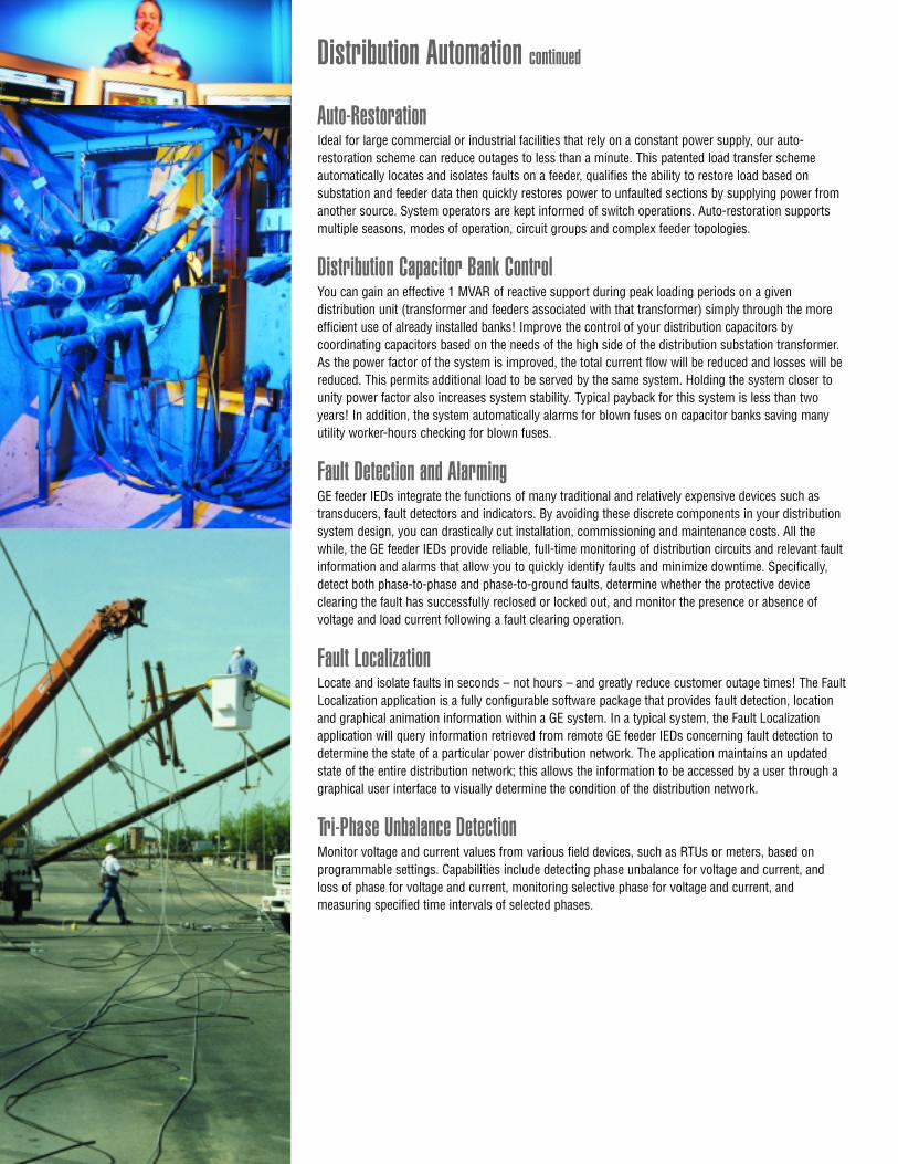
Distribution Automation continued

ENHANCED SCADAThese invaluable programs carry out fundamental functions within the SCADA system. Althoughthey are simple in themselves, these SCADA applications are indispensable for efficientlycollecting and coordinating real-time and/or historic data for use by other automation applications,the master station or operator monitoring and control.
Accumulator FreezeDetect status changes initiated by other GE applications. One or more accumulators can be frozenwhen a status input changes state and/or automatically on a configured time interval, for example,once an hour. An optional control output can be operated to externally indicate the accumulatorshave been frozen.
Analog ReferenceThe Analog Reference application is a simple way to monitor the status of analog input fielddevices. It monitors analog input points that are connected to analog input hardware, andprovides the system database with pseudo analog values. These values represent either correctlyfunctioning analog input hardware (good reference value), or failed analog input hardware (badreference value).
Communication WatchdogThe Communication Watchdog monitors the state of communication between a GE system andconnected IEDs. When the GE system is attempting communication with the IEDs, theCommunication Watchdog can indicate whether the devices and/or individual points are on-line or off-line. In a redundant system, the Communication Watchdog indicates which physical unit isactive and shows the current readiness state of the secondary unit. All indications can be used toraise alarms, if desired.
Data Change DetectionSend indications to other applications whenever changes occur on user-defined groups of points.This application can monitor multiple groups of points, and toggle digital inputs if any changesoccur within the user-defined groups. Digital input, digital output, counter, analog input, andanalog output groups can all be monitored.
Event StorageStore up to seven days of events in the GE device’s Non-Volatile Memory (NVRAM) for access byother applications. Accumulator and analog point values can be queried and stored on aconfigurable time interval. Data is time and date stamped, as it is stored. Locally and remotelydisplay and print the stored data using Wesmaint.
SOE Local LoggerLog sequence of events data by monitoring any subset of digital inputs. As time-tagged statuschanges occur, all or a subset of the events can be printed at a local printer or stored in a file onthe RTU to be uploaded at a later time. The log includes an alarm description, point number, dateand time (to the nearest millisecond).
And more applications –Contact GE Energy Services for moreinformation on our other applicationsbuilt for the power industry.
• Convert a group of digital inputs toan analog input
• Convert an analog output to a groupof digital outputs formatted as binaryon BCD
• Monitor an accumulator input andstore the change in counts in ananalog input
• Convert an analog input to a group ofdigital outputs
• Monitor an analog input andmaintain an alarm indicating thevalue has exceeded a configuredthreshold
• Monitor an analog input andrecord, at a configured interval,an integrating type of average
• Monitor a group of digital inputsand report the associated tapposition in an analog input
• Latch a digital input statechange until it is acknowledgedby an operator
• Automatically reclose a trippedcircuit breaker
• Gain Master Local/Remotefunctionality by monitoring a digitalinput and enabling or disabling agroup of substation control relays

SYSTEM COMMUNICATIONSChances are, we already speak your language. We offer the most extensive library of utility communication protocols in theworld, meaning we can pretty well get almost any host and any end device and anything in between talking for little cost. Ourprotocol library includes standards-based protocols, legacy protocols and IED interfaces.
Standards-Based ProtocolsIndustry standard protocols are our standard. Using industry standard technology gives you the flexibility to adapt to changingand growing business needs.
Internet ProtocolsThe Internet Protocol (IP) suite over Ethernet is an inexpensive and widely available approach to achieving an open local areanetwork within your substation. Choosing the almost universally used IP suite facilitates the integration of substation protectionand control, and real-time and historical data with the utility’s existing applications for the storage and analysis of data acrossthe enterprise. The open LAN solution provides improved operational efficiency through fast, dependable, retrieval of data overthe network.
GE Energy Services offers further reliability by including dual redundant LAN interfaces as a standard option on all our integratedSubstation Control Systems. Our implementation includes TCP, IP, UDP, ICMP, ARP, TFTP, BOOTP, PPP and Telnet. In today’squickly changing environment, GE’s open LAN solution provides a flexible migration path for future expansions and upgrades.
DNP3The Distributed Network Protocol (DNP) offers the flexibility and functionality that goes well beyond other utility communicationprotocols. Developed by GE Energy Services in the early 1990s, and now under the control and stewardship of an independentusers group, DNP3 has been adopted by hundreds of utilities around the world, is implemented by over 200 vendors, and isan IEEE® recommended practice (RP-1379) for intelligent electronic device communications. DNP3 is an effective and reliableprotocol for a wide range of communications media, including over serial or LAN/WAN. GE Energy Services continues tocontribute to the DNP Technical Committee to ensure our leadership in implementing new features as they are developed.
IEC® 60870-5The IEC® 60870-5 suite of protocols is being used around the world for communications from master station to substation, aswell as within the substation. GE Energy Services supports a comprehensive set of applications and a superior implementationof the functions that this international standard protocol suite provides, including:• IEC® 60870-5-101 Telecontrol (controlling or controlled station)• IEC® 60870-5 FT1.2 Balanced and unbalanced mode (data link layer)• IEC® 60870-5-103 Protection equipment (controlling station)• IEC® 60870-5-104 LAN/WAN access
GE Energy Services remains in touch with changes to the IEC® 60870-5 standards, implementing amendments and users groupconventions as they are issued.
UCA™ 2.0GE Energy Services was one of the first suppliers to demonstrate a Utility Communications Architecture (UCA™) implementationand continues to be a leading contributor to the development and demonstration of this protocol suite. GE Energy Services is anational representative on the committees developing IEC® 61850, the international standard version of UCA™ 2.0. Ourimplementations include both IP and OSI versions of the protocol suite and support a wide variety of object models to ensureinteroperability as the protocol matures. Our soon to be released UCA™ data-processing application will include support for theInter-Control Center Communications Protocol (ICCP, also known as TASE.2 or IEC® 60870-6).

ABB® Power T&DABB® Systems Control –
Advanced Control SystemsAllen-Bradley® Alstom™APT Power TechnologiesArga ControlsBasler® ElectricBeckwith® Electric®
Bitronics® IncCellnet® Data SystemsCooper Power Systems®
Electro IndustriesEnergyline® SystemsEnvicFluke®
FoxboroGE FanucGE IndustrialGE Power ManagementGE SyprotecGPI Mexicana Alta Tech.H&L InstrumentsHathaway Automation TechnologiesItron® Inc.Landis & Gyr®
Mehta TechModicon®
Nu-Lec GroupOntario HydroPower Measurement Ltd.
Process Systems Inc.Reinhausen™RFL ElectronicsRochester InstrumentsSchlumberger®
Schweitzer Engineering Laboratories (SEL®)
Scientific Columbus®
Second Wind®
Siemens® Energy & AutomationU.S. PowerThe Valley GroupVA Tech™Valmet® Automation
ABB® Indactic 33/41 (16-bit)ABB® Indactic 35ABB® Systems Control SC1801ADLP-180AMTRAK™ SDLCAllen-Bradley® ANSI® X3.28ASWBBC 7200Boeing™ BETAC/GETAC® 7020CDC® 44-500 Type ICDC® 44-550 Type IICegelec® HNZConitel C0300Conitel C0200Conitel C2000Conitel C2020Conitel C2025Conitel C2100H
Conitel C2100MConitel C3000Datap DCP-1ESCA/WELCOFerranti® Mark IIAFerranti® TRW 9550Ferranti® TRW S9000Ferranti® VancommGETAC® 7020GETAC® 7020 LPGeorgia Power CompanyHarris® HR5000Harris® HR6000/XA-21Harris® Micro IILandis & Gyr® 8979Megadata MD3000Modbus® (RTU & ASCII modes)MPS 9000
Pert 26/31PG&E® (Rev. 11)QEI Rockwell®
SANGAMOSCADA Consultants (Sensa)SES®-91SES®-92Siemens® Sinaut® 8FW-1024 (DPDM)Siemens® Sinaut® 8FW-512 (PCM)Telegyr® TG809Valmet® TEJAS VValmet® TEJAS IIIWestinghouse® REDAC 70HWestinghouse® WESDAC 4FWestinghouse® WISP+
ABB®Indactic 33ABB®Systems Control 1801CDC® Type IICegelec® HNZ
Ferranti® VancommLandis & Gyr® 8979Harris® HR6000Harris® Micro II
Megadata MD3000Modbus® (RTU & ASCII modes)Rockwell®
Siemens® Sinaut® 8FW-512 (PCM)
Master Station/Host ProtocolsWe provide the communications gateway from your central station to the rest of your transmission and distribution network.
SubmasterCommunicate reliably with legacy remote units and systems.
IED InterfacesGE Energy Services excels in concentrating data to/from intelligent electronic devices from many manufacturers usingindustry standard or proprietary protocols. Extend your monitoring and control abilities by reaching out to the remotedevices at the outer limits of your transmission and distribution system.
“Tacoma Power has
upgraded D200 and
D25 based Ethernet LANs
in transmission and
distribution substations to
a company-wide SCADA
WAN. The WAN, which
enables remote access to
all substation IEDs through
a Virtual Connection from
anywhere in the utility,
helps us improve
operational efficiency
and increase system
reliability by efficiently
transferring information to
operations staff.”
Tacoma Power Company,
Washington, USA
Communication InterfacesCommunications are the backbone of your SCADA system. All GE systems operate effectively within all communicationsnetworks to reliably transmit and receive data when needed as needed.
• Leased-line telephone • Dial-up telephone • Licensed/unlicensed UHF/VHF• Packet Switching Network • CDPD (cellular digital packet data) • Analog cellular• Satellite • Power line carrier • Ethernet LAN/WAN
• Wireless