Embed Size (px)
Citation preview
160 Laser & Photon. Rev. 4, No. 1, 160–177 (2010) / DOI 10.1002/lpor.200810060
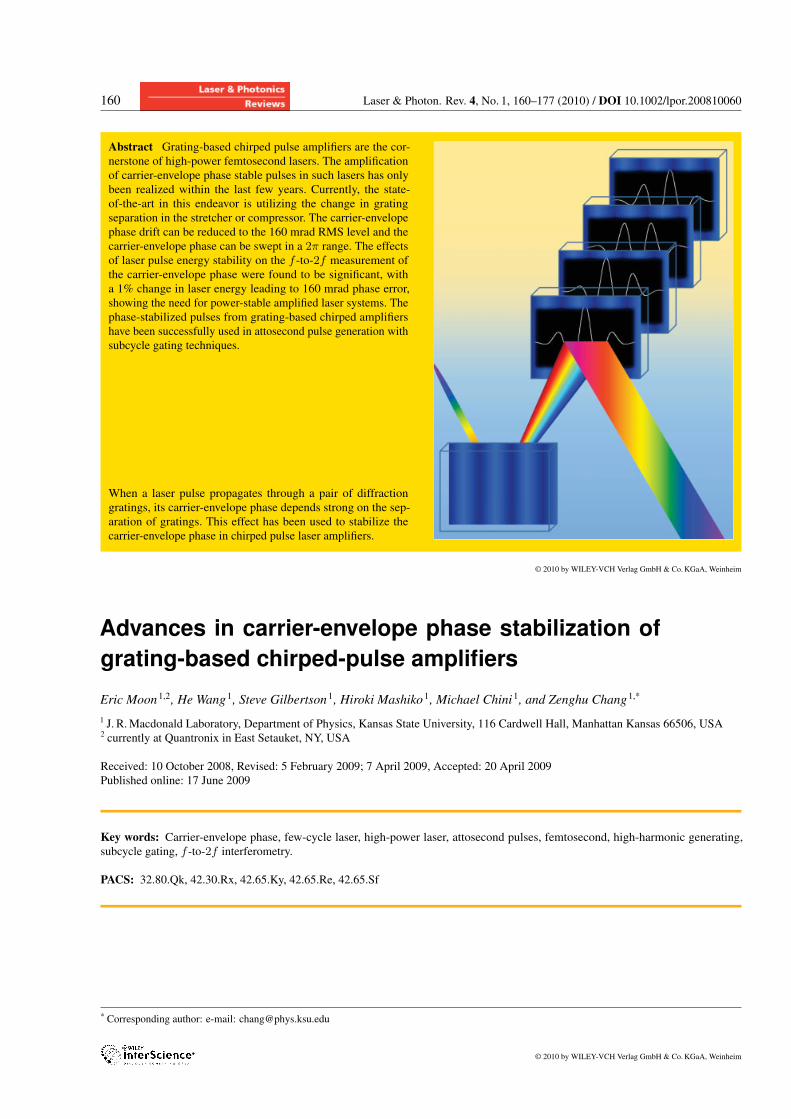
Abstract Grating-based chirped pulse amplifiers are the cor-
nerstone of high-power femtosecond lasers. The amplification
of carrier-envelope phase stable pulses in such lasers has only
been realized within the last few years. Currently, the state-
of-the-art in this endeavor is utilizing the change in grating
separation in the stretcher or compressor. The carrier-envelope
phase drift can be reduced to the 160 mrad RMS level and the
carrier-envelope phase can be swept in a 2π range. The effectsof laser pulse energy stability on the f -to-2f measurement ofthe carrier-envelope phase were found to be significant, with
a 1% change in laser energy leading to 160 mrad phase error,
showing the need for power-stable amplified laser systems. The
phase-stabilized pulses from grating-based chirped amplifiers
have been successfully used in attosecond pulse generation with
subcycle gating techniques.
When a laser pulse propagates through a pair of diffraction
gratings, its carrier-envelope phase depends strong on the sep-
aration of gratings. This effect has been used to stabilize the
carrier-envelope phase in chirped pulse laser amplifiers.
© 2010 by WILEY-VCH Verlag GmbH & Co.KGaA, Weinheim
Advances in carrier-envelope phase stabilization ofgrating-based chirped-pulse amplifiers
Eric Moon1,2, He Wang1, Steve Gilbertson1, Hiroki Mashiko1, Michael Chini1, and Zenghu Chang1,*
1 J. R.Macdonald Laboratory, Department of Physics, Kansas State University, 116 Cardwell Hall, Manhattan Kansas 66506, USA2 currently at Quantronix in East Setauket, NY, USA
Received: 10 October 2008, Revised: 5 February 2009; 7 April 2009, Accepted: 20 April 2009
Published online: 17 June 2009
Key words: Carrier-envelope phase, few-cycle laser, high-power laser, attosecond pulses, femtosecond, high-harmonic generating,subcycle gating, f -to-2f interferometry.
PACS: 32.80.Qk, 42.30.Rx, 42.65.Ky, 42.65.Re, 42.65.Sf
* Corresponding author: e-mail: [email protected]
© 2010 by WILEY-VCH Verlag GmbH & Co.KGaA, Weinheim
Laser & Photon. Rev. 4, No. 1 (2010) 161
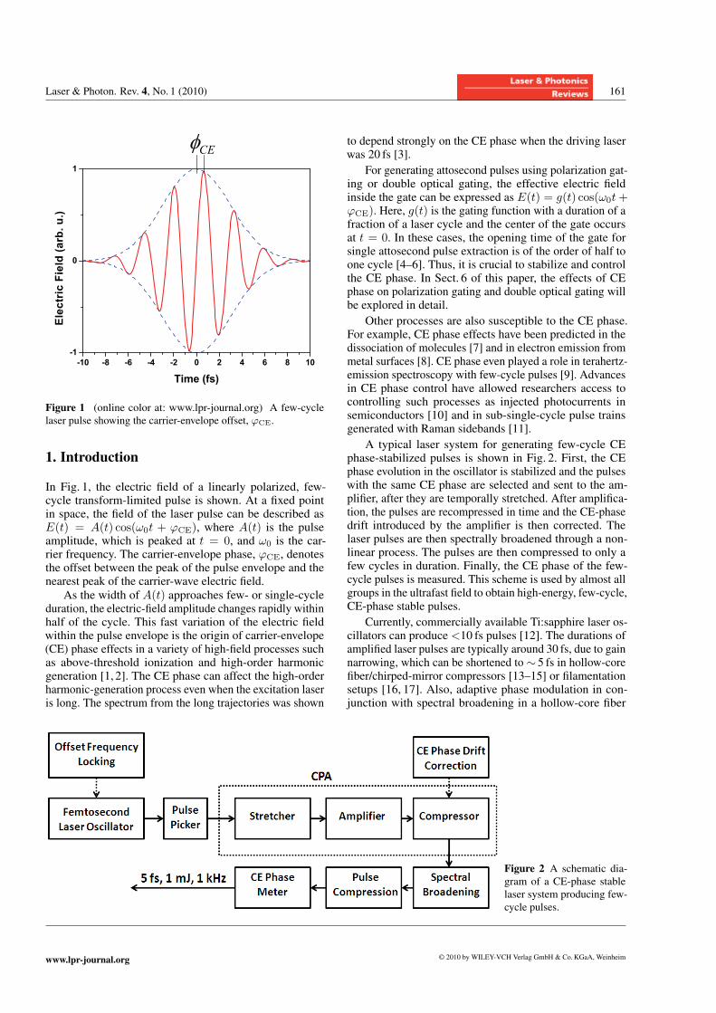
Figure 1 (online color at: www.lpr-journal.org) A few-cycle
laser pulse showing the carrier-envelope offset, ϕCE.
1. Introduction
In Fig. 1, the electric field of a linearly polarized, few-cycle transform-limited pulse is shown. At a fixed pointin space, the field of the laser pulse can be described asE(t) = A(t) cos(ω0t + ϕCE), where A(t) is the pulseamplitude, which is peaked at t = 0, and ω0 is the car-rier frequency. The carrier-envelope phase, ϕCE, denotesthe offset between the peak of the pulse envelope and thenearest peak of the carrier-wave electric field.As the width of A(t) approaches few- or single-cycle
duration, the electric-field amplitude changes rapidly withinhalf of the cycle. This fast variation of the electric fieldwithin the pulse envelope is the origin of carrier-envelope(CE) phase effects in a variety of high-field processes suchas above-threshold ionization and high-order harmonicgeneration [1, 2]. The CE phase can affect the high-orderharmonic-generation process even when the excitation laseris long. The spectrum from the long trajectories was shown
to depend strongly on the CE phase when the driving laserwas 20 fs [3].
For generating attosecond pulses using polarization gat-ing or double optical gating, the effective electric fieldinside the gate can be expressed as E(t) = g(t) cos(ω0t+ϕCE). Here, g(t) is the gating function with a duration of afraction of a laser cycle and the center of the gate occursat t = 0. In these cases, the opening time of the gate forsingle attosecond pulse extraction is of the order of half toone cycle [4–6]. Thus, it is crucial to stabilize and controlthe CE phase. In Sect. 6 of this paper, the effects of CEphase on polarization gating and double optical gating willbe explored in detail.
Other processes are also susceptible to the CE phase.For example, CE phase effects have been predicted in thedissociation of molecules [7] and in electron emission frommetal surfaces [8]. CE phase even played a role in terahertz-emission spectroscopy with few-cycle pulses [9]. Advancesin CE phase control have allowed researchers access tocontrolling such processes as injected photocurrents insemiconductors [10] and in sub-single-cycle pulse trainsgenerated with Raman sidebands [11].
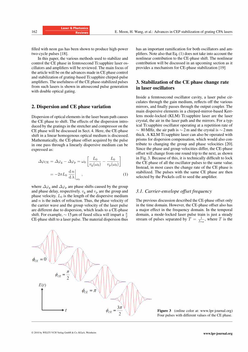
A typical laser system for generating few-cycle CEphase-stabilized pulses is shown in Fig. 2. First, the CEphase evolution in the oscillator is stabilized and the pulseswith the same CE phase are selected and sent to the am-plifier, after they are temporally stretched. After amplifica-tion, the pulses are recompressed in time and the CE-phasedrift introduced by the amplifier is then corrected. Thelaser pulses are then spectrally broadened through a non-linear process. The pulses are then compressed to only afew cycles in duration. Finally, the CE phase of the few-cycle pulses is measured. This scheme is used by almost allgroups in the ultrafast field to obtain high-energy, few-cycle,CE-phase stable pulses.
Currently, commercially available Ti:sapphire laser os-cillators can produce <10 fs pulses [12]. The durations ofamplified laser pulses are typically around 30 fs, due to gainnarrowing, which can be shortened to ∼ 5 fs in hollow-corefiber/chirped-mirror compressors [13–15] or filamentationsetups [16, 17]. Also, adaptive phase modulation in con-junction with spectral broadening in a hollow-core fiber
Figure 2 A schematic dia-gram of a CE-phase stable
laser system producing few-
cycle pulses.
www.lpr-journal.org © 2010 by WILEY-VCH Verlag GmbH & Co.KGaA, Weinheim
162 E. Moon, H. Wang, et al.: Advances in CEP stabilization of grating CPA lasers
filled with neon gas has been shown to produce high-powertwo-cycle pulses [18].In this paper, the various methods used to stabilize and
control the CE phase in femtosecond Ti:sapphire laser os-cillators and amplifiers will be reviewed. The main focus ofthe article will be on the advances made in CE phase controland stabilization of grating-based Ti:sapphire chirped-pulseamplifiers. The usefulness of the CE phase-stabilized pulsesfrom such lasers is shown in attosecond pulse generationwith double optical gating.
2. Dispersion and CE phase variation
Dispersion of optical elements in the laser beam path causesthe CE phase to shift. The effects of the dispersion intro-duced by the gratings in the stretcher and compressor on theCE phase will be discussed in Sect. 4. Here, the CE-phaseshift in a linear homogenous optical medium is discussed.Mathematically, the CE-phase offset acquired by the pulsein one pass through a linearly dispersive medium can beexpressed as:
ΔϕCE = Δϕg −Δϕp = ω0
[L0
vg(ω0)− L0
vp(ω0)
]
= −2πL0dndλ
∣∣∣∣ω0
, (1)
where Δϕg and Δϕp are phase shifts caused by the groupand phase delay, respectively. vg and vp are the group andphase velocity. L0 is the length of the dispersive mediumand n is the index of refraction. Thus, the phase velocity ofthe carrier wave and the group velocity of the laser pulseare different due to dispersion, which leads to a CE-phaseshift. For example, ∼ 15 μm of fused silica will impart a π
2CE-phase shift to a laser pulse. The material dispersion thus
has an important ramification for both oscillators and am-plifiers. Note also that Eq. (1) does not take into account thenonlinear contribution to the CE-phase shift. The nonlinearcontribution will be discussed in an upcoming section as itprovides a mechanism for CE-phase stabilization [19]
3. Stabilization of the CE phase change ratein laser oscillators
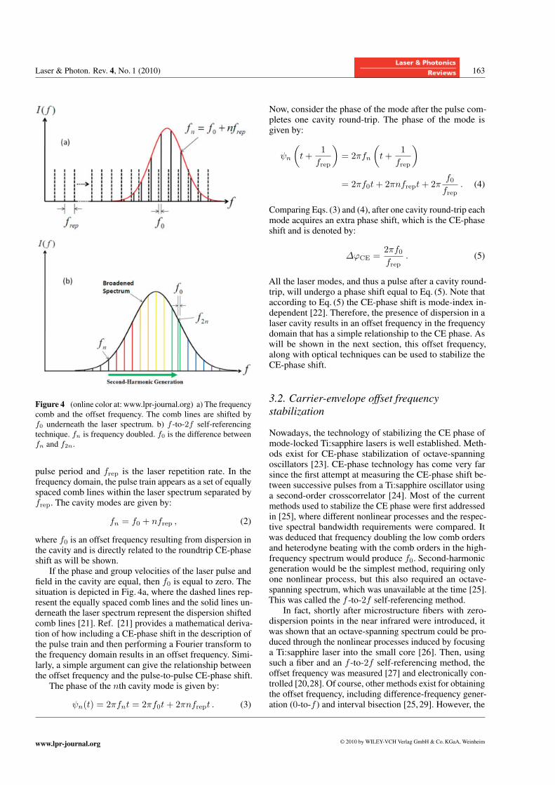
Inside a femtosecond oscillator cavity, a laser pulse cir-culates through the gain medium, reflects off the variousmirrors, and finally passes through the output coupler. Themain dispersive elements in a chirped-mirror-based Kerr-lens mode-locked (KLM) Ti:sapphire laser are the lasercrystal, the air in the laser path and the mirrors. For a typ-ical Ti:sapphire oscillator operating at a repetition rate of∼ 80MHz, the air path is ∼ 2m and the crystal is ∼ 2mmthick. A KLM Ti:sapphire laser can also be operated withprisms for dispersion compensation, which would also con-tribute to changing the group and phase velocities [20].Since the phase and group velocities differ, the CE-phaseoffset will change from one round trip to the next, as shownin Fig. 3. Because of this, it is technically difficult to lockthe CE phase of all the oscillator pulses to the same value.Instead, in most cases the change rate of the CE phase isstabilized. The pulses with the same CE phase are thenselected by the Pockels cell to seed the amplifier.
3.1. Carrier-envelope offset frequency
The previous discussion described the CE-phase offset onlyin the time domain. However, the CE-phase offset also hasa major effect in the frequency domain. In the temporaldomain, a mode-locked laser pulse train is just a steadystream of pulses separated by T = 1
frep, where T is the
Figure 3 (online color at: www.lpr-journal.org)
Four pulses with different values of the CE phase.
© 2010 by WILEY-VCH Verlag GmbH & Co.KGaA, Weinheim www.lpr-journal.org
Laser & Photon. Rev. 4, No. 1 (2010) 163
Figure 4 (online color at: www.lpr-journal.org) a) The frequency
comb and the offset frequency. The comb lines are shifted by
f0 underneath the laser spectrum. b) f -to-2f self-referencingtechnique. fn is frequency doubled. f0 is the difference between
fn and f2n.
pulse period and frep is the laser repetition rate. In thefrequency domain, the pulse train appears as a set of equallyspaced comb lines within the laser spectrum separated byfrep. The cavity modes are given by:
fn = f0 + nfrep , (2)
where f0 is an offset frequency resulting from dispersion inthe cavity and is directly related to the roundtrip CE-phaseshift as will be shown.If the phase and group velocities of the laser pulse and
field in the cavity are equal, then f0 is equal to zero. Thesituation is depicted in Fig. 4a, where the dashed lines rep-resent the equally spaced comb lines and the solid lines un-derneath the laser spectrum represent the dispersion shiftedcomb lines [21]. Ref. [21] provides a mathematical deriva-tion of how including a CE-phase shift in the description ofthe pulse train and then performing a Fourier transform tothe frequency domain results in an offset frequency. Simi-larly, a simple argument can give the relationship betweenthe offset frequency and the pulse-to-pulse CE-phase shift.The phase of the nth cavity mode is given by:
ψn(t) = 2πfnt = 2πf0t+ 2πnfrept . (3)
Now, consider the phase of the mode after the pulse com-pletes one cavity round-trip. The phase of the mode isgiven by:
ψn
(t+
1frep
)= 2πfn
(t+
1frep
)
= 2πf0t+ 2πnfrept+ 2πf0frep
. (4)
Comparing Eqs. (3) and (4), after one cavity round-trip eachmode acquires an extra phase shift, which is the CE-phaseshift and is denoted by:
ΔϕCE =2πf0frep
. (5)
All the laser modes, and thus a pulse after a cavity round-trip, will undergo a phase shift equal to Eq. (5). Note thataccording to Eq. (5) the CE-phase shift is mode-index in-dependent [22]. Therefore, the presence of dispersion in alaser cavity results in an offset frequency in the frequencydomain that has a simple relationship to the CE phase. Aswill be shown in the next section, this offset frequency,along with optical techniques can be used to stabilize theCE-phase shift.
3.2. Carrier-envelope offset frequencystabilization
Nowadays, the technology of stabilizing the CE phase ofmode-locked Ti:sapphire lasers is well established. Meth-ods exist for CE-phase stabilization of octave-spanningoscillators [23]. CE-phase technology has come very farsince the first attempt at measuring the CE-phase shift be-tween successive pulses from a Ti:sapphire oscillator usinga second-order crosscorrelator [24]. Most of the currentmethods used to stabilize the CE phase were first addressedin [25], where different nonlinear processes and the respec-tive spectral bandwidth requirements were compared. Itwas deduced that frequency doubling the low comb ordersand heterodyne beating with the comb orders in the high-frequency spectrum would produce f0. Second-harmonicgeneration would be the simplest method, requiring onlyone nonlinear process, but this also required an octave-spanning spectrum, which was unavailable at the time [25].This was called the f -to-2f self-referencing method.In fact, shortly after microstructure fibers with zero-
dispersion points in the near infrared were introduced, itwas shown that an octave-spanning spectrum could be pro-duced through the nonlinear processes induced by focusinga Ti:sapphire laser into the small core [26]. Then, usingsuch a fiber and an f -to-2f self-referencing method, theoffset frequency was measured [27] and electronically con-trolled [20,28]. Of course, other methods exist for obtainingthe offset frequency, including difference-frequency gener-ation (0-to-f ) and interval bisection [25, 29]. However, the
www.lpr-journal.org © 2010 by WILEY-VCH Verlag GmbH & Co.KGaA, Weinheim
164 E. Moon, H. Wang, et al.: Advances in CEP stabilization of grating CPA lasers
majority of groups use the f -to-2f method, which will bediscussed in this section.
Fig. 4b shows the principle of the f -to-2f self-referenc-ing method. The original laser spectrum is broadened overan octave in frequency. Then, the low-frequency compo-nents are frequency doubled and interfered with the highcomb orders [30]. Mathematically, the heterodyne beatresulting from the aforementioned process can be repre-sented as:
2fn − f2n = 2(nfrep + f0)− (2nfrep + f0) = f0 . (6)
Thus, the difference between the f and 2f comb orders isthe offset frequency.
The next step in the process of locking the CE phase isto track the offset frequency and lock it to either zero fre-quency [31] or to an integer fraction of the laser repetitionrate using a servo loop [32]. Locking the offset frequencyto a fraction of the laser repetition rate is the most com-mon method as the repetition rate is easily accessible. Twofast mechanisms can be used to lock the offset frequencyto a fixed value. The first method involves tilting a mir-ror in the cavity to change the path length, which onlyworks for prism-based lasers [33, 34]. The second, and themore common, method is to modulate the pump powerwith an acousto-optic modulator (AOM). Modulating thepump power changes the nonlinearity in the crystal, whichalso changes the refractive index and thus the group andphase velocities [35, 36].
3.3. The effects of f -to-2f interferometers
Several studies have been conducted on the quality of CE-phase stabilization systems. It was found that laser-powerstability was a factor when determining the offset frequencyusing a nonlinear fiber [37]. The authors measured theamplitude-to-phase coupling coefficient of the microstruc-ture fiber and found a value of 3784 rad/nJ, which wasquite large and showed the need for good laser-power sta-bility. In other research by the same group, they measuredthe in- and out-of-loop accumulated phase noise when theoscillator was locked and unlocked. It was found that theout-of-loop phase noise was slightly higher due to mechan-ical vibrations in the optical mounts used to stabilize theCE phase, which indicated the locking servo was writingextra CE-phase noise onto the output pulses [38].The noise introduced by path-length fluctuation in the
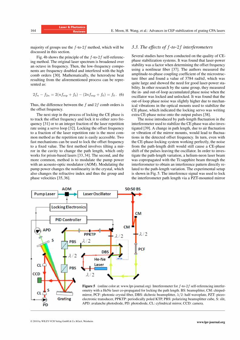
interferometer used to stabilize the CE phase was also inves-tigated [39]. A change in path length, due to air fluctuationor vibration of the mirror mounts, would lead to fluctua-tions in the detected offset frequency. In turn, even withthe CE-phase-locking system working perfectly, the noisefrom the path-length drift would still cause a CE-phaseshift of the pulses leaving the oscillator. In order to inves-tigate the path-length variation, a helium-neon laser beamwas copropagated with the Ti:sapphire beam through theinterferometer to obtain an interference pattern directly re-lated to the path-length variation. The experimental setupis shown in Fig. 5. The interference signal was used to lockthe interferometer path length via a PZT-mounted mirror
Figure 5 (online color at: www.lpr-journal.org) Interferometer for f -to-2f self-referencing interfer-ometry with a HeNe laser co-propagated for locking the path length. BS: beamsplitter, CM: chirped-
mirror, PCF: photonic crystal fiber, DBS: dichroic beamsplitter, λ/2: half-waveplate, PZT: piezo-electronic transducer, PPKTP: periodically poled KTP, PBS: polarizing beamsplitter cube, S: slit,
APD: avalanche photodiode, PD: photodiode, CL: cylindrical mirror, CCD: camera.
© 2010 by WILEY-VCH Verlag GmbH & Co.KGaA, Weinheim www.lpr-journal.org
Laser & Photon. Rev. 4, No. 1 (2010) 165
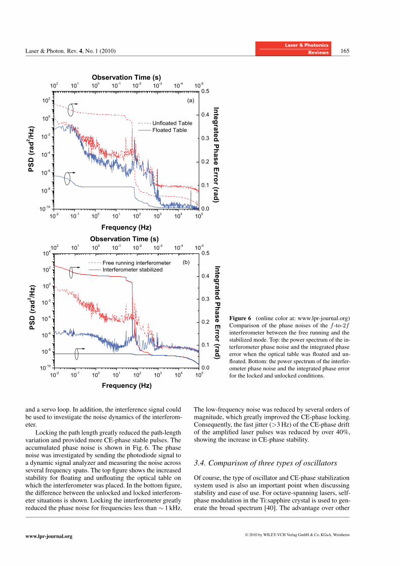
Figure 6 (online color at: www.lpr-journal.org)
Comparison of the phase noises of the f -to-2finterferometer between the free running and the
stabilized mode. Top: the power spectrum of the in-
terferometer phase noise and the integrated phase
error when the optical table was floated and un-
floated. Bottom: the power spectrum of the interfer-
ometer phase noise and the integrated phase error
for the locked and unlocked conditions.
and a servo loop. In addition, the interference signal couldbe used to investigate the noise dynamics of the interferom-eter.
Locking the path length greatly reduced the path-lengthvariation and provided more CE-phase stable pulses. Theaccumulated phase noise is shown in Fig. 6. The phasenoise was investigated by sending the photodiode signal toa dynamic signal analyzer and measuring the noise acrossseveral frequency spans. The top figure shows the increasedstability for floating and unfloating the optical table onwhich the interferometer was placed. In the bottom figure,the difference between the unlocked and locked interferom-eter situations is shown. Locking the interferometer greatlyreduced the phase noise for frequencies less than ∼ 1 kHz.
The low-frequency noise was reduced by several orders ofmagnitude, which greatly improved the CE-phase locking.Consequently, the fast jitter (>3Hz) of the CE-phase driftof the amplified laser pulses was reduced by over 40%,showing the increase in CE-phase stability.
3.4. Comparison of three types of oscillators
Of course, the type of oscillator and CE-phase stabilizationsystem used is also an important point when discussingstability and ease of use. For octave-spanning lasers, self-phase modulation in the Ti:sapphire crystal is used to gen-erate the broad spectrum [40]. The advantage over other
www.lpr-journal.org © 2010 by WILEY-VCH Verlag GmbH & Co.KGaA, Weinheim
166 E. Moon, H. Wang, et al.: Advances in CEP stabilization of grating CPA lasers
oscillator designs is that the entire laser output can be usedfor seeding an amplifier or for other experiments. Also,shorter pulses can usually be produced since the spectrumis so broad. For such a laser, however, the crystal can eas-ily be damaged. Creating the extra frequency componentsbeyond the gain spectrum of Ti:sapphire requires a highintensity in the laser crystal. Also, the alignment of the lasercavity is more difficult than for conventional Ti:sapphirelaser oscillatorsFor conventional Ti:sapphire oscillators, the spectrum
is narrower than that of octave-spanning lasers, but the in-tensity in the laser crystal is lower and the alignment ofthe cavity is simpler. However, in order to stabilize the CEphase, the spectrum must be broadened to obtain the offsetfrequency. The advantage is the ease of use of the system.As was said before, the disadvantages in this situation arethe path-length drift in the f -to-2f , amplitude/phase cou-pling in the PCF, and a portion of the laser output must besplit off to be focused in the PCF.A compromise exists when the laser output from a
broadband Ti:sapphire oscillator is focused into a nonlin-ear crystal, in which spectral broadening and DFG occur.These processes provide access to the offset frequency. Theadvantages are that the majority of the laser output wouldbe available and a collinear interferometer could be used toobtain the offset frequency [41]. The disadvantage, though,is the pulse quality from the laser. Pre- and post-pulses existin the output temporal profile, which can be detrimental toexperiments. Also, a somewhat higher intensity must bemaintained in the laser crystal for some spectral broaden-ing.
4. CE-phase stabilization and control ofamplified laser pulses
The pulse energy of typical Ti:sapphire laser oscillatorsis on the nJ level, which is not enough for studying themajority of high-field physical processes sensitive to theCE phase, such as ATI [42]. Therefore, the oscillator pulsesmust undergo amplification to reach higher energies. Themost common method for obtaining high-energy pulsesis to stretch the pulses in time, amplify them, and thentemporally compress them. This scheme is called chirped-pulse amplification (CPA) and is a well-established tech-nology [43–45]. However, in order to obtain high-energyCE-phase stable pulses, any drift introduced during theamplification process must be corrected.Early investigations of amplifying CE-phase stable
pulses focused on identifying and quantifying sources ofphase drift [30, 46]. The measurement technique used wascalled Fourier-transform spectral interferometery (FTSI),whereby the amplified pulses were spectrally broadenedover an octave using a nonlinear process, the second har-monic of the long-wavelength components was taken, andthe second harmonic and fundamental were overlapped andinterfered [47]. Note that this is the method used by almost
all groups to measure the CE-phase stability of amplifiedlaser pulses.It was determined that the CPA process only caused
a small, slow drift of the CE phase, which could beprecompensated using the oscillator CE-phase lockingservo [48–50]. However, the early CE-phase stable am-plifiers used glass blocks in the stretchers and prisms in thecompressors. These amplifiers could not be scaled up to themulti-mJ level due to the low damage threshold and nonlin-ear effects of the material in the stretchers and compressors.Therefore, grating-based CPAs were desired as the gratingscould handle the higher laser energies. It was initially be-lieved that the CE phase would experience more fluctuationwith the grating-based stretchers and compressors; however,it was shown that high-energy CE-phase stable pulses couldbe obtained from a grating-based CPA [51,52].
4.1. CE-phase shift caused by grating pairs
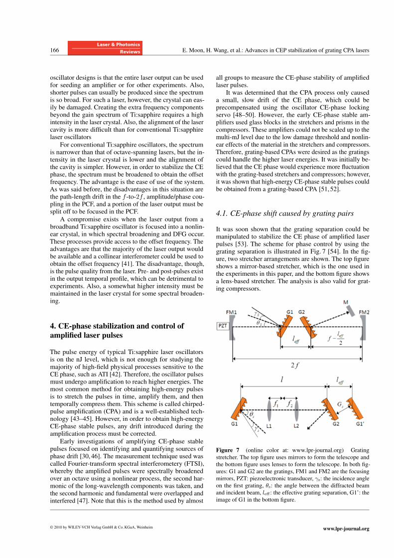
It was soon shown that the grating separation could bemanipulated to stabilize the CE phase of amplified laserpulses [53]. The scheme for phase control by using thegrating separation is illustrated in Fig. 7 [54]. In the fig-ure, two stretcher arrangements are shown. The top figureshows a mirror-based stretcher, which is the one used inthe experiments in this paper, and the bottom figure showsa lens-based stretcher. The analysis is also valid for grat-ing compressors.
Figure 7 (online color at: www.lpr-journal.org) Grating
stretcher. The top figure uses mirrors to form the telescope and
the bottom figure uses lenses to form the telescope. In both fig-
ures: G1 and G2 are the gratings, FM1 and FM2 are the focusing
mirrors, PZT: piezoelectronic transducer, γs: the incidence angle
on the first grating, θs: the angle between the diffracted beam
and incident beam, leff : the effective grating separation, G1’: theimage of G1 in the bottom figure.
© 2010 by WILEY-VCH Verlag GmbH & Co.KGaA, Weinheim www.lpr-journal.org
Laser & Photon. Rev. 4, No. 1 (2010) 167
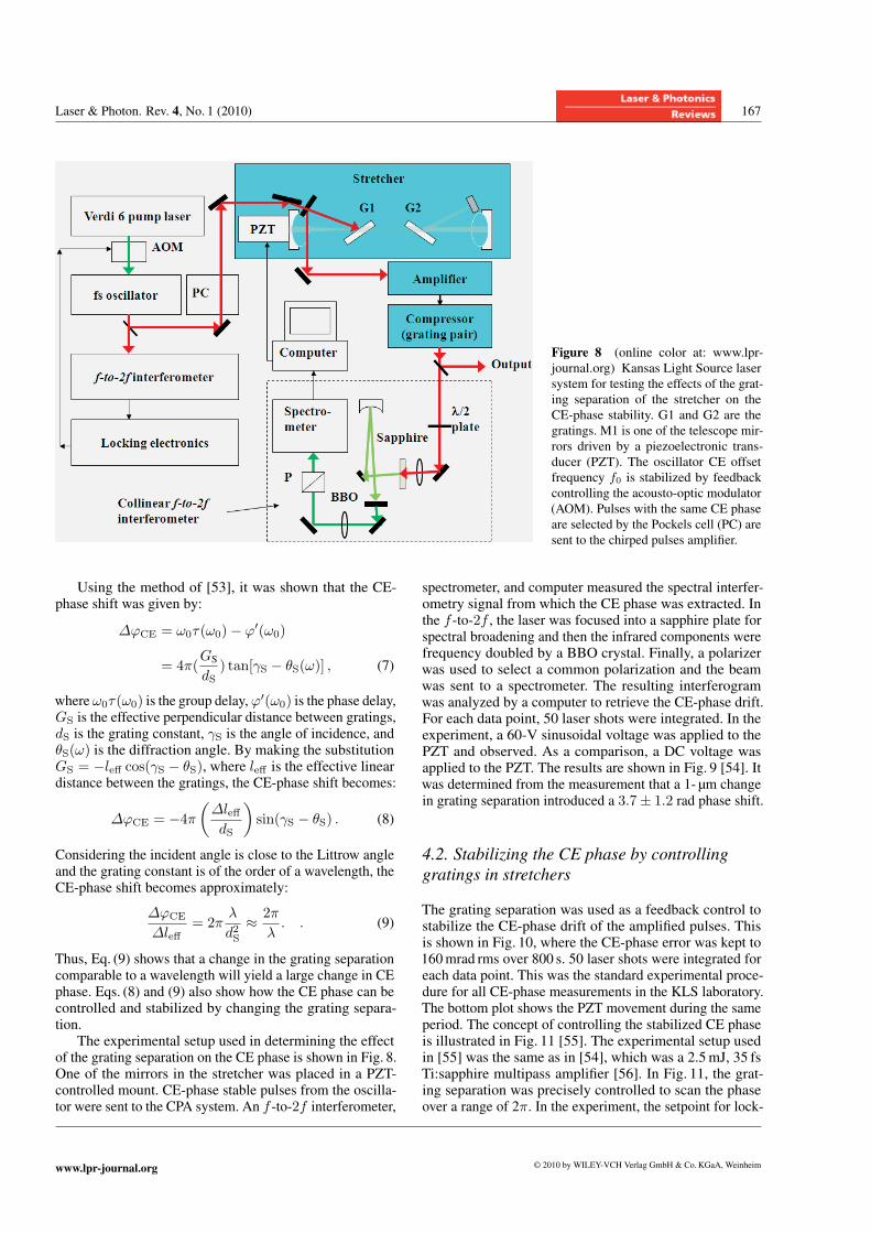
Figure 8 (online color at: www.lpr-
journal.org) Kansas Light Source laser
system for testing the effects of the grat-
ing separation of the stretcher on the
CE-phase stability. G1 and G2 are the
gratings. M1 is one of the telescope mir-
rors driven by a piezoelectronic trans-
ducer (PZT). The oscillator CE offset
frequency f0 is stabilized by feedback
controlling the acousto-optic modulator
(AOM). Pulses with the same CE phase
are selected by the Pockels cell (PC) are
sent to the chirped pulses amplifier.
Using the method of [53], it was shown that the CE-phase shift was given by:
ΔϕCE = ω0τ(ω0)− ϕ′(ω0)
= 4π(GSdS
) tan[γS − θS(ω)] , (7)
where ω0τ(ω0) is the group delay,ϕ′(ω0) is the phase delay,GS is the effective perpendicular distance between gratings,dS is the grating constant, γS is the angle of incidence, andθS(ω) is the diffraction angle. By making the substitutionGS = −leff cos(γS − θS), where leff is the effective lineardistance between the gratings, the CE-phase shift becomes:
ΔϕCE = −4π(ΔleffdS
)sin(γS − θS) . (8)
Considering the incident angle is close to the Littrow angleand the grating constant is of the order of a wavelength, theCE-phase shift becomes approximately:
ΔϕCE
Δleff= 2π
λ
d2S
≈ 2πλ. . (9)
Thus, Eq. (9) shows that a change in the grating separationcomparable to a wavelength will yield a large change in CEphase. Eqs. (8) and (9) also show how the CE phase can becontrolled and stabilized by changing the grating separa-tion.The experimental setup used in determining the effect
of the grating separation on the CE phase is shown in Fig. 8.One of the mirrors in the stretcher was placed in a PZT-controlled mount. CE-phase stable pulses from the oscilla-tor were sent to the CPA system. An f -to-2f interferometer,
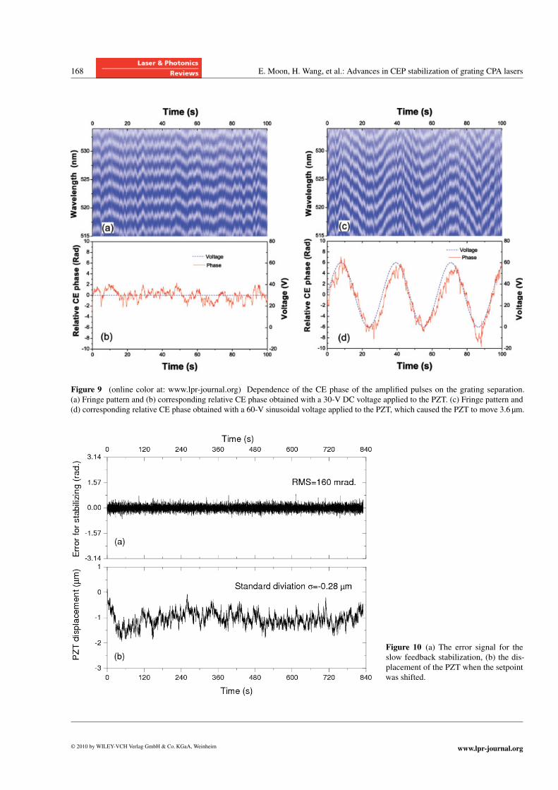
spectrometer, and computer measured the spectral interfer-ometry signal from which the CE phase was extracted. Inthe f -to-2f , the laser was focused into a sapphire plate forspectral broadening and then the infrared components werefrequency doubled by a BBO crystal. Finally, a polarizerwas used to select a common polarization and the beamwas sent to a spectrometer. The resulting interferogramwas analyzed by a computer to retrieve the CE-phase drift.For each data point, 50 laser shots were integrated. In theexperiment, a 60-V sinusoidal voltage was applied to thePZT and observed. As a comparison, a DC voltage wasapplied to the PZT. The results are shown in Fig. 9 [54]. Itwas determined from the measurement that a 1- μm changein grating separation introduced a 3.7± 1.2 rad phase shift.
4.2. Stabilizing the CE phase by controllinggratings in stretchers
The grating separation was used as a feedback control tostabilize the CE-phase drift of the amplified pulses. Thisis shown in Fig. 10, where the CE-phase error was kept to160mrad rms over 800 s. 50 laser shots were integrated foreach data point. This was the standard experimental proce-dure for all CE-phase measurements in the KLS laboratory.The bottom plot shows the PZT movement during the sameperiod. The concept of controlling the stabilized CE phaseis illustrated in Fig. 11 [55]. The experimental setup usedin [55] was the same as in [54], which was a 2.5mJ, 35 fsTi:sapphire multipass amplifier [56]. In Fig. 11, the grat-ing separation was precisely controlled to scan the phaseover a range of 2π. In the experiment, the setpoint for lock-
www.lpr-journal.org © 2010 by WILEY-VCH Verlag GmbH & Co.KGaA, Weinheim
168 E. Moon, H. Wang, et al.: Advances in CEP stabilization of grating CPA lasers
Figure 9 (online color at: www.lpr-journal.org) Dependence of the CE phase of the amplified pulses on the grating separation.
(a) Fringe pattern and (b) corresponding relative CE phase obtained with a 30-V DC voltage applied to the PZT. (c) Fringe pattern and
(d) corresponding relative CE phase obtained with a 60-V sinusoidal voltage applied to the PZT, which caused the PZT to move 3.6 μm.
Figure 10 (a) The error signal for theslow feedback stabilization, (b) the dis-
placement of the PZT when the setpoint
was shifted.
© 2010 by WILEY-VCH Verlag GmbH & Co.KGaA, Weinheim www.lpr-journal.org
Laser & Photon. Rev. 4, No. 1 (2010) 169
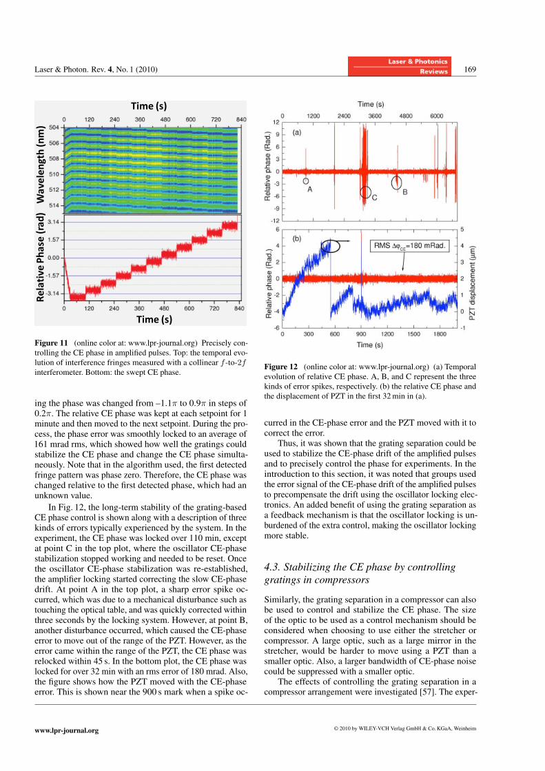
Figure 11 (online color at: www.lpr-journal.org) Precisely con-
trolling the CE phase in amplified pulses. Top: the temporal evo-
lution of interference fringes measured with a collinear f -to-2finterferometer. Bottom: the swept CE phase.
ing the phase was changed from –1.1π to 0.9π in steps of0.2π. The relative CE phase was kept at each setpoint for 1minute and then moved to the next setpoint. During the pro-cess, the phase error was smoothly locked to an average of161 mrad rms, which showed how well the gratings couldstabilize the CE phase and change the CE phase simulta-neously. Note that in the algorithm used, the first detectedfringe pattern was phase zero. Therefore, the CE phase waschanged relative to the first detected phase, which had anunknown value.
In Fig. 12, the long-term stability of the grating-basedCE phase control is shown along with a description of threekinds of errors typically experienced by the system. In theexperiment, the CE phase was locked over 110 min, exceptat point C in the top plot, where the oscillator CE-phasestabilization stopped working and needed to be reset. Oncethe oscillator CE-phase stabilization was re-established,the amplifier locking started correcting the slow CE-phasedrift. At point A in the top plot, a sharp error spike oc-curred, which was due to a mechanical disturbance such astouching the optical table, and was quickly corrected withinthree seconds by the locking system. However, at point B,another disturbance occurred, which caused the CE-phaseerror to move out of the range of the PZT. However, as theerror came within the range of the PZT, the CE phase wasrelocked within 45 s. In the bottom plot, the CE phase waslocked for over 32 min with an rms error of 180 mrad. Also,the figure shows how the PZT moved with the CE-phaseerror. This is shown near the 900 s mark when a spike oc-
Figure 12 (online color at: www.lpr-journal.org) (a) Temporal
evolution of relative CE phase. A, B, and C represent the three
kinds of error spikes, respectively. (b) the relative CE phase and
the displacement of PZT in the first 32min in (a).
curred in the CE-phase error and the PZT moved with it tocorrect the error.
Thus, it was shown that the grating separation could beused to stabilize the CE-phase drift of the amplified pulsesand to precisely control the phase for experiments. In theintroduction to this section, it was noted that groups usedthe error signal of the CE-phase drift of the amplified pulsesto precompensate the drift using the oscillator locking elec-tronics. An added benefit of using the grating separation asa feedback mechanism is that the oscillator locking is un-burdened of the extra control, making the oscillator lockingmore stable.
4.3. Stabilizing the CE phase by controllinggratings in compressors
Similarly, the grating separation in a compressor can alsobe used to control and stabilize the CE phase. The sizeof the optic to be used as a control mechanism should beconsidered when choosing to use either the stretcher orcompressor. A large optic, such as a large mirror in thestretcher, would be harder to move using a PZT than asmaller optic. Also, a larger bandwidth of CE-phase noisecould be suppressed with a smaller optic.The effects of controlling the grating separation in a
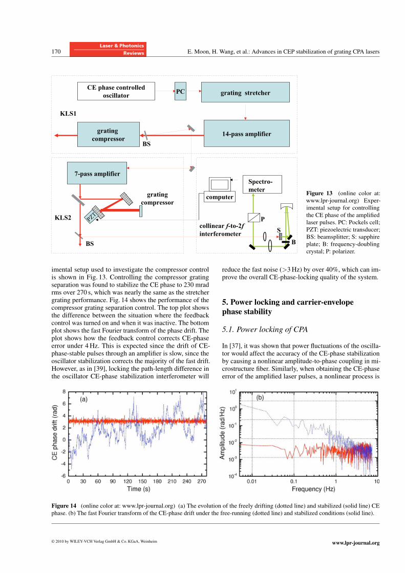
compressor arrangement were investigated [57]. The exper-
www.lpr-journal.org © 2010 by WILEY-VCH Verlag GmbH & Co.KGaA, Weinheim
170 E. Moon, H. Wang, et al.: Advances in CEP stabilization of grating CPA lasers
Figure 13 (online color at:
www.lpr-journal.org) Exper-
imental setup for controlling
the CE phase of the amplified
laser pulses. PC: Pockels cell;
PZT: piezoelectric transducer;
BS: beamsplitter; S: sapphire
plate; B: frequency-doubling
crystal; P: polarizer.
imental setup used to investigate the compressor controlis shown in Fig. 13. Controlling the compressor gratingseparation was found to stabilize the CE phase to 230 mradrms over 270 s, which was nearly the same as the stretchergrating performance. Fig. 14 shows the performance of thecompressor grating separation control. The top plot showsthe difference between the situation where the feedbackcontrol was turned on and when it was inactive. The bottomplot shows the fast Fourier transform of the phase drift. Theplot shows how the feedback control corrects CE-phaseerror under 4Hz. This is expected since the drift of CE-phase-stable pulses through an amplifier is slow, since theoscillator stabilization corrects the majority of the fast drift.However, as in [39], locking the path-length difference inthe oscillator CE-phase stabilization interferometer will
reduce the fast noise (>3Hz) by over 40%, which can im-prove the overall CE-phase-locking quality of the system.
5. Power locking and carrier-envelopephase stability
5.1. Power locking of CPA
In [37], it was shown that power fluctuations of the oscilla-tor would affect the accuracy of the CE-phase stabilizationby causing a nonlinear amplitude-to-phase coupling in mi-crostructure fiber. Similarly, when obtaining the CE-phaseerror of the amplified laser pulses, a nonlinear process is
Figure 14 (online color at: www.lpr-journal.org) (a) The evolution of the freely drifting (dotted line) and stabilized (solid line) CE
phase. (b) The fast Fourier transform of the CE-phase drift under the free-running (dotted line) and stabilized conditions (solid line).
© 2010 by WILEY-VCH Verlag GmbH & Co.KGaA, Weinheim www.lpr-journal.org
Laser & Photon. Rev. 4, No. 1 (2010) 171
Figure 15 (online color at: www.lpr-
journal.org) The Kansas Light Source (KLS)
laser-intensity-stabilization system. The in-
loop powermeter was put in the path of
the zero-order diffraction beam and sent the
power signal to the PID controller. By using
feedback control, the PID varied the volt-
age applied on the Pockels cell, which in
turn changed the polarization of the output
from the oscillator and stabilized the laser
intensity. Red arrows are the laser paths and
dashed arrows represent electronic circuits.
used, such as self-phase modulation, to broaden the pulsespectrum over an octave in order to perform f -to-2f inter-ferometry [47]. Usually, the Ti:sapphire laser is focusedinto a bulk material, such as sapphire, to generate the octave-spanning spectrum. Therefore, the nonlinear process shouldbe susceptible to intensity fluctuations that would also af-fect the measured CE phase.
The energy fluctuation of typical diode-pumped kilo-hertz femtosecond laser systems is around 1.5% RMS, evenwhen placed in a well-controlled environment and allowedhours of warm-up time. In order to increase the energystability of those systems, a power-locking system was de-veloped, which measured the power after the amplifier and
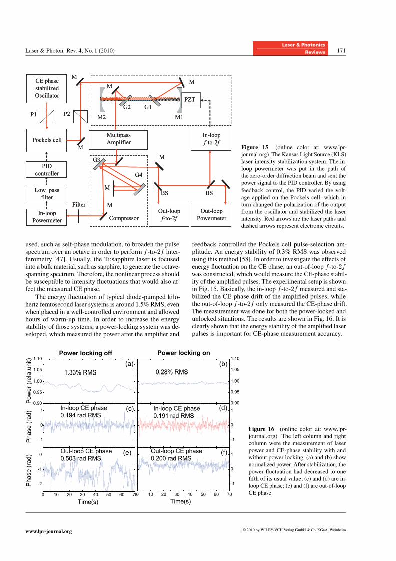
feedback controlled the Pockels cell pulse-selection am-plitude. An energy stability of 0.3% RMS was observedusing this method [58]. In order to investigate the effects ofenergy fluctuation on the CE phase, an out-of-loop f -to-2fwas constructed, which would measure the CE-phase stabil-ity of the amplified pulses. The experimental setup is shownin Fig. 15. Basically, the in-loop f -to-2f measured and sta-bilized the CE-phase drift of the amplified pulses, whilethe out-of-loop f -to-2f only measured the CE-phase drift.The measurement was done for both the power-locked andunlocked situations. The results are shown in Fig. 16. It isclearly shown that the energy stability of the amplified laserpulses is important for CE-phase measurement accuracy.
Figure 16 (online color at: www.lpr-
journal.org) The left column and right
column were the measurement of laser
power and CE-phase stability with and
without power locking. (a) and (b) show
normalized power. After stabilization, the
power fluctuation had decreased to one
fifth of its usual value; (c) and (d) are in-
loop CE phase; (e) and (f) are out-of-loop
CE phase.
www.lpr-journal.org © 2010 by WILEY-VCH Verlag GmbH & Co.KGaA, Weinheim
172 E. Moon, H. Wang, et al.: Advances in CEP stabilization of grating CPA lasers
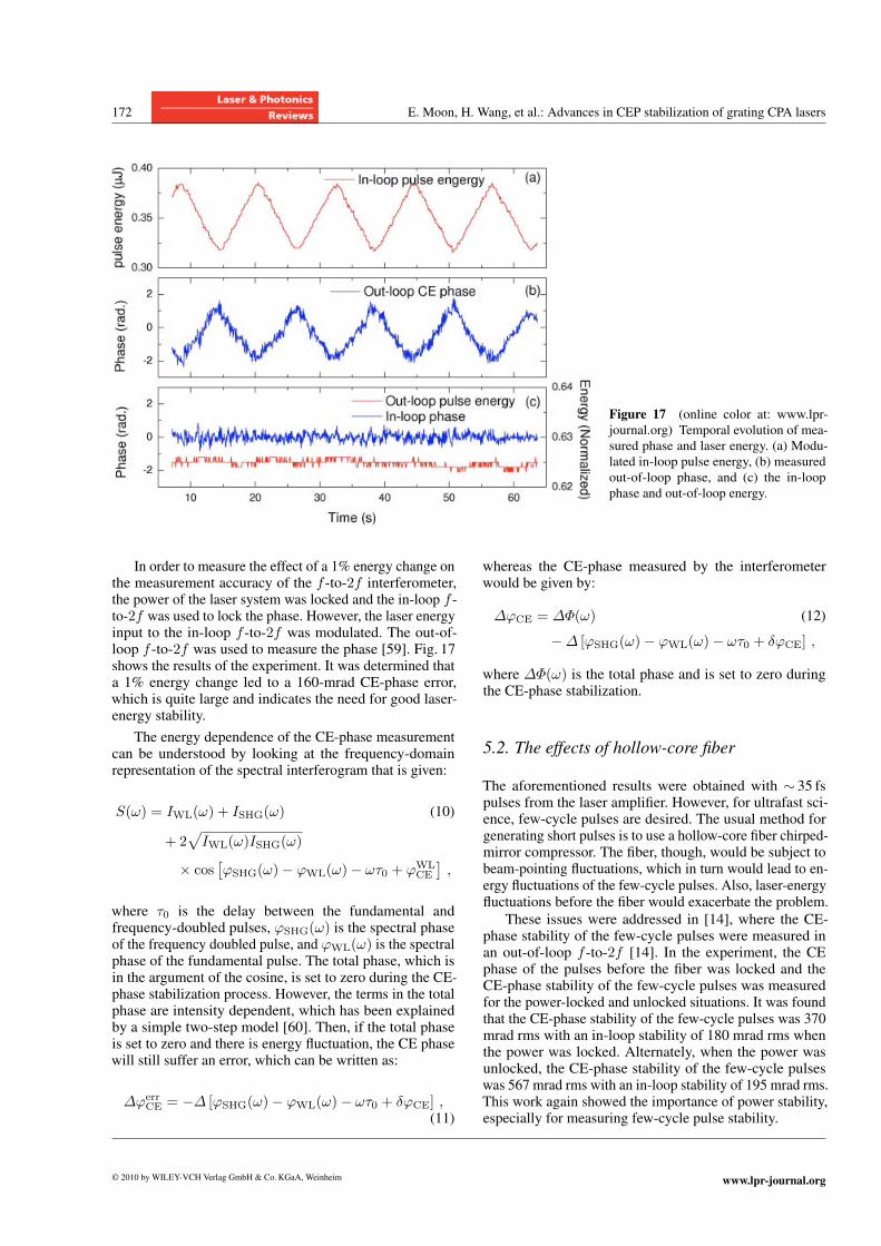
Figure 17 (online color at: www.lpr-
journal.org) Temporal evolution of mea-
sured phase and laser energy. (a) Modu-
lated in-loop pulse energy, (b) measured
out-of-loop phase, and (c) the in-loop
phase and out-of-loop energy.
In order to measure the effect of a 1% energy change onthe measurement accuracy of the f -to-2f interferometer,the power of the laser system was locked and the in-loop f -to-2f was used to lock the phase. However, the laser energyinput to the in-loop f -to-2f was modulated. The out-of-loop f -to-2f was used to measure the phase [59]. Fig. 17shows the results of the experiment. It was determined thata 1% energy change led to a 160-mrad CE-phase error,which is quite large and indicates the need for good laser-energy stability.
The energy dependence of the CE-phase measurementcan be understood by looking at the frequency-domainrepresentation of the spectral interferogram that is given:
S(ω) = IWL(ω) + ISHG(ω) (10)
+ 2√IWL(ω)ISHG(ω)
× cos[ϕSHG(ω)− ϕWL(ω)− ωτ0 + ϕWL
CE
],
where τ0 is the delay between the fundamental andfrequency-doubled pulses, ϕSHG(ω) is the spectral phaseof the frequency doubled pulse, and ϕWL(ω) is the spectralphase of the fundamental pulse. The total phase, which isin the argument of the cosine, is set to zero during the CE-phase stabilization process. However, the terms in the totalphase are intensity dependent, which has been explainedby a simple two-step model [60]. Then, if the total phaseis set to zero and there is energy fluctuation, the CE phasewill still suffer an error, which can be written as:
ΔϕerrCE = −Δ [ϕSHG(ω)− ϕWL(ω)− ωτ0 + δϕCE] ,
(11)
whereas the CE-phase measured by the interferometerwould be given by:
ΔϕCE = ΔΦ(ω) (12)
−Δ [ϕSHG(ω)− ϕWL(ω)− ωτ0 + δϕCE] ,
where ΔΦ(ω) is the total phase and is set to zero duringthe CE-phase stabilization.
5.2. The effects of hollow-core fiber
The aforementioned results were obtained with ∼ 35 fspulses from the laser amplifier. However, for ultrafast sci-ence, few-cycle pulses are desired. The usual method forgenerating short pulses is to use a hollow-core fiber chirped-mirror compressor. The fiber, though, would be subject tobeam-pointing fluctuations, which in turn would lead to en-ergy fluctuations of the few-cycle pulses. Also, laser-energyfluctuations before the fiber would exacerbate the problem.
These issues were addressed in [14], where the CE-phase stability of the few-cycle pulses were measured inan out-of-loop f -to-2f [14]. In the experiment, the CEphase of the pulses before the fiber was locked and theCE-phase stability of the few-cycle pulses was measuredfor the power-locked and unlocked situations. It was foundthat the CE-phase stability of the few-cycle pulses was 370mrad rms with an in-loop stability of 180 mrad rms whenthe power was locked. Alternately, when the power wasunlocked, the CE-phase stability of the few-cycle pulseswas 567 mrad rms with an in-loop stability of 195 mrad rms.This work again showed the importance of power stability,especially for measuring few-cycle pulse stability.
© 2010 by WILEY-VCH Verlag GmbH & Co.KGaA, Weinheim www.lpr-journal.org

Laser & Photon. Rev. 4, No. 1 (2010) 173
6. Double optical gating with CEphase-stabilized pulses
6.1. Single isolated attosecond pulses
Recently, single attosecond pulse production has become ahot topic in the ultrafast optics field [61]. Such extremelyshort XUV pulses are powerful tools for studying elec-tron dynamics in atoms and molecules [62]. This new lightsource is based on high-order harmonic generation (HHG),which is a nonperturbative nonlinear optic process discov-ered around 1987–1988 [63]. When a linearly polarized,short pulse laser beam interacts with noble gases, odd har-monics of the fundamental frequency, up to hundreds inorder, emerge in the output beam. According to the semi-classical model, when the laser intensity approaches a frac-tion of one atomic unit (3.55× 10¹⁶ W/cm2), an electronwavepacket first moves away from the nucleus of the tar-get atom through tunneling, then is driven back. Finally,it recombines with the parent ion with the emission of acoherent burst of X-rays [64, 65]. These three steps occurwithin one laser cycle. When all electrons released near onepeak of a laser cycle are considered, the emitted photonsform an attosecond pulse. Since there are two field max-ima in one laser cycle, two attosecond pulses are generatedby those electrons that take the “short trajectories”. For alaser pulse that contains many cycles, an attosecond pulsetrain is produced [66]. The pulse train corresponds to dis-crete harmonic peaks in the frequency domain, which is thehigh-harmonic spectrum.When the duration of the laser pulse approaches one
cycle, the harmonic peaks in the cutoff region merge into acontinuum, which has been filtered out to produce singleisolated attosecond pulses [67]. The shortest pulse gen-erated so far is 80 attoseconds. Single isolated attosecondpulses can also be extracted by a scheme called polarizationgating [68, 69]. It uses a laser field with a rapidly changingellipticity. Since XUV attosecond pulses can only be effi-ciently generated with linearly polarized driving fields, asingle attosecond pulse is emitted if the laser field is lin-early polarized in only a short time range and ellipticallypolarized in the other portion of the driving pulse. The timerange over which the attosecond pulse is generated is calledthe polarization gate. This scheme was demonstrated with5-fs lasers [70]. However, it is still a technical challenge toreproduce daily laser pulses with one- to two-cycle duration.We developed a double optical gating (DOG) technique forgenerating single isolated attosecond pulses with multicyclepump lasers [5].
6.2. Double optical gating
The double optical gating combines polarization gatingwith a weak second-harmonic field. The polarization gat-ing field can be created by adding two circularly polarizedpulses together. The field synthesis can be done with bire-fringence optics. Details of the experimental setup can be
found in [6]. This method allows the linear portion of theellipticity dependent pulse to be a full optical cycle of theinput pulse as compared to the half-optical-cycle require-ments of polarization gating alone.The laser field for the double optical gating can be
resolved into a driving field and gating field, E(t) =Edrive(t)i + Egate(t)j, where i and j are the unit vec-tors in the x and y directions, respectively. The drivingfield generates the attosecond pulses, whereas the gatingfield suppresses attosecond emissions except the one in themiddle of the laser pulse. The driving field is
Edrive(t) =E0
[(e−2 ln 2
(t+Td/2)2
τ2p + e
−2 ln 2(t−Td/2)2
τ2p
)
× cos(ω0t+ ϕCE)
+ aω,2ω
(2 e−2 ln 2
“Td/2
τp
”2)e−2 ln 2 t2
τ22ω
× cos(2ω0t+ 2ϕCE + ϕω,2ω)
](13)
and the gating field is
Egate(t) =
E0
(e−2 ln 2
(t+Td/2−Tω/4)2
τ2p − e
−2 ln 2(t−Td/2−Tω/4)2
τ2p
)
× sin (ω0t+ ϕCE) , (14)
where E0 is the amplitude of the circularly polarized fun-damental laser field with a carrier frequency ω0 and a pulseduration τp. The delay, T0/4, between the gating and thedriving fields is introduced by a quarter-wave plate for cre-ating the circular light. ϕCE is the carrier-envelope phaseof the fundamental laser fields. The carrier-envelope phaseof the second-harmonic field is 2ϕCE. aω,2ω is the ratio ofthe amplitudes between the second-harmonic field and thedriving field at the center of the polarization gate (t = 0).The relative phase delay between the two fields isϕω,2ω
when ϕCE = 0.
6.3. The effects of CE phase on the gatedXUV spectra
Since the effective generation portion of the input pulse is asingle cycle or less, the CE-phase dependence exhibits verystrong features. Fig. 18 shows the field within the linearportion of the ellipticity dependent pulse. The vertical linesindicate the “gate width” which is the linear portion actuallyresponsible for generating a single pulse. The figure alsoshows that as the CE phase of the input pulse changes, theattosecond pulses that are generated can change in intensityand be either a single pulse or a set of two pulses. Due to
www.lpr-journal.org © 2010 by WILEY-VCH Verlag GmbH & Co.KGaA, Weinheim
174 E. Moon, H. Wang, et al.: Advances in CEP stabilization of grating CPA lasers
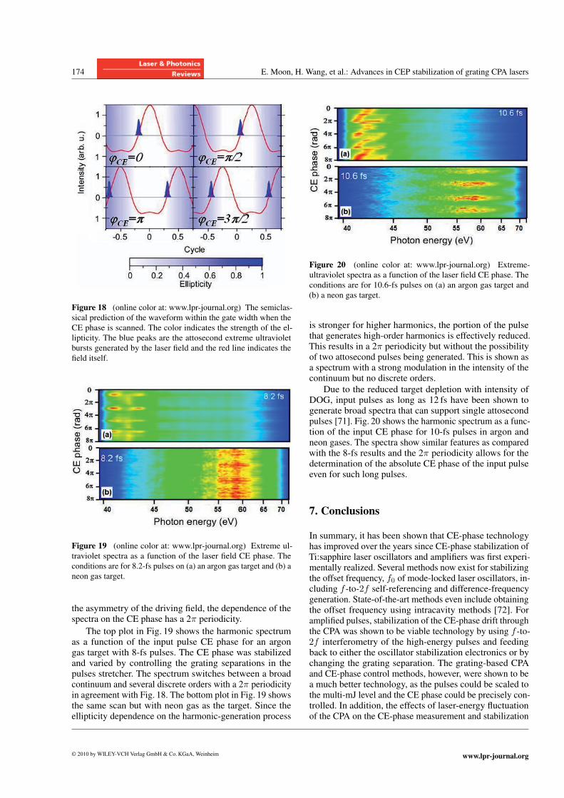
Figure 18 (online color at: www.lpr-journal.org) The semiclas-
sical prediction of the waveform within the gate width when the
CE phase is scanned. The color indicates the strength of the el-
lipticity. The blue peaks are the attosecond extreme ultraviolet
bursts generated by the laser field and the red line indicates the
field itself.
Figure 19 (online color at: www.lpr-journal.org) Extreme ul-
traviolet spectra as a function of the laser field CE phase. The
conditions are for 8.2-fs pulses on (a) an argon gas target and (b) a
neon gas target.
the asymmetry of the driving field, the dependence of thespectra on the CE phase has a 2π periodicity.
The top plot in Fig. 19 shows the harmonic spectrumas a function of the input pulse CE phase for an argongas target with 8-fs pulses. The CE phase was stabilizedand varied by controlling the grating separations in thepulses stretcher. The spectrum switches between a broadcontinuum and several discrete orders with a 2π periodicityin agreement with Fig. 18. The bottom plot in Fig. 19 showsthe same scan but with neon gas as the target. Since theellipticity dependence on the harmonic-generation process
Figure 20 (online color at: www.lpr-journal.org) Extreme-
ultraviolet spectra as a function of the laser field CE phase. The
conditions are for 10.6-fs pulses on (a) an argon gas target and
(b) a neon gas target.
is stronger for higher harmonics, the portion of the pulsethat generates high-order harmonics is effectively reduced.This results in a 2π periodicity but without the possibilityof two attosecond pulses being generated. This is shown asa spectrum with a strong modulation in the intensity of thecontinuum but no discrete orders.
Due to the reduced target depletion with intensity ofDOG, input pulses as long as 12 fs have been shown togenerate broad spectra that can support single attosecondpulses [71]. Fig. 20 shows the harmonic spectrum as a func-tion of the input CE phase for 10-fs pulses in argon andneon gases. The spectra show similar features as comparedwith the 8-fs results and the 2π periodicity allows for thedetermination of the absolute CE phase of the input pulseeven for such long pulses.
7. Conclusions
In summary, it has been shown that CE-phase technologyhas improved over the years since CE-phase stabilization ofTi:sapphire laser oscillators and amplifiers was first experi-mentally realized. Several methods now exist for stabilizingthe offset frequency, f0 of mode-locked laser oscillators, in-cluding f -to-2f self-referencing and difference-frequencygeneration. State-of-the-art methods even include obtainingthe offset frequency using intracavity methods [72]. Foramplified pulses, stabilization of the CE-phase drift throughthe CPA was shown to be viable technology by using f -to-2f interferometry of the high-energy pulses and feedingback to either the oscillator stabilization electronics or bychanging the grating separation. The grating-based CPAand CE-phase control methods, however, were shown to bea much better technology, as the pulses could be scaled tothe multi-mJ level and the CE phase could be precisely con-trolled. In addition, the effects of laser-energy fluctuationof the CPA on the CE-phase measurement and stabilization
© 2010 by WILEY-VCH Verlag GmbH & Co.KGaA, Weinheim www.lpr-journal.org
Laser & Photon. Rev. 4, No. 1 (2010) 175
were studied and were found to be significant. The laserenergy fluctuation, therefore, should be kept below 1% forreliable CE-phase measurement and stabilization. This wasespecially evident for short pulse generation using a hollow-core fiber chirped-mirror compressor. Therefore, CE-phasestable and controllable high-energy pulses are now a viabletechnology for studying ultrafast science.
Challenges do lie ahead for CE-phase-stabilization tech-nology. For example, adaptive pulse shaping is a methodwhere the phase of the laser pulse can be manipulated. Ifthis method is combined with CE-phase stabilization andcontrol, it could allow for the generation of ultrashort pulseswith precise control of the absolute phase. Also, by improv-ing the power stability of few-cycle pulses generated fromfilamentation or hollow-core fiber chirped-mirror compres-sors, the CE phase of short pulses could be more finelycontrolled. Finally, the majority of the work with CE-phasestabilization and control of amplified laser pulses has beenwith multipass Ti:sapphire amplifiers. To date, no group hasactively stabilized and controlled the CE phase of regener-ative amplifiers. This is also one of the major challengesstill facing CE-phase researchers. Thus, there is room toimprove in the area of CE-phase stabilization and controlof Ti:sapphire laser oscillators and amplifiers.
Acknowledgements The authors would like to thank all of thecurrent and former members of the Kansas Light Source research
group for helpful discussions, design of equipment, and further
assistance. This work was supported by the Chemical Sciences,
Geosciences and Biosciences Division, Office of Basic Energy
Sciences, Office of Science, U. S. Department of Energy, by the
National Science Foundation under grant No. 0457269, and by
the U. S. Army Research Office under grant number W911NF-07-
1-0475.
Eric Moon graduated with a B. S.in Physics from Baker University inBaldwin City, KS in 2003. He fin-ished a Ph.D. in Physics at KansasState University in December 2008.His research was focused on carrier-envelope stabilization of Ti:sapphirelasers and amplifiers. He currentlyworks for Quantronix in East Se-
tauket, NY.
He Wang received his B.S degree inphysics from University of Scienceand Technology of China in 2005.Currently, he is a fourth-year gradu-ate student in the physics departmentat Kansas State University. His cur-rent research is mainly focused on thegeneration of CE-phase-controllableshort pulses with a pulse shaper and
their applications.
Steve Gilbertson received the B. S.degree from Kansas State Univer-sity in 2005. He is currently work-ing toward the Ph.D. degree fromKansas State University, Manhattan,Kansas. His research interests in-clude applications of soft X-ray radi-ation from high-harmonic generationand attosecond science.
Hiroki Mashiko received the B. S.and M. S. degrees from Tokai Univer-sity, Department of Physics, Kana-gawa, Japan, in 2001 and 2003, re-spectively. The Ph.D. degree wasreceived from Saitama University,Graduate School of Science and En-gineering, Saitama, Japan in 2006.From April 2003–2006, he was a Ju-
nior Research Associate at the Institute of Physical andChemical Research (RIKEN), Laser Technology Lab-oratory, Japan. From March 2006, he joined as a Post-Doctoral Research Associate at Kansas State University,Department of Physics, USA.
Michael Chini received his B. S. de-gree in physics from McGill Uni-versity in 2007. He is currently inthe second year of his Ph. D. studiesin the physics department at KansasState University. His current researchis mainly focused on single attosec-ond pulse generation and characteri-zation.
Dr. Zenghu Chang is a professor ofphysics at Kansas State University.He received his doctorate in Opticsat the Xi’an Institute of Optics andPrecision Mechanics at the ChineseAcademy of Sciences in 1988. Heserved as an associate professor atthis intuition for the next three yearsbefore joining the Rutherford Apple-
ton Laboratory in the UK. Dr. Chang moved to the USin 1995 with a position at Washington State Universityas an adjunct professor and visiting scientist. In 1996 hemoved to the University of Michigan as a research fel-low and then as an Assistant research scientist. In 2001he joined the faculty at Kansas State University and in2006 was appointed full professor in the Department ofPhysics. Most recently Dr. Chang was awarded a Merca-tor Professorship, by the German Science Foundation.He now serves as the chair of the attoscience technique
www.lpr-journal.org © 2010 by WILEY-VCH Verlag GmbH & Co.KGaA, Weinheim
176 E. Moon, H. Wang, et al.: Advances in CEP stabilization of grating CPA lasers
group of the Optical Society of America. His researchactivities include the area of coherent extreme ultravioletattosecond sources from high-order harmonic genera-tion.
References
[1] G. G. Paulus, F. Grasbon, H. Walther, P. Villoresi, M. Nisoli,
S. Stagira, E. Priori, and S. De Silvestri, Nature (London)
414, 182 (2001).[2] C.A. Haworth, L. E. Chipperfield, J. S. Robinson,
P. L. Knight, J. P. Marangos, and J.W.G. Tisch, Nature
Phys. 3, 52 (2007).[3] G. Sansone, C. Vozzi, S. Stagira, M. Pascolini, L. Poletto,
P. Villoresi, G. Tondello, S. De Silvestri, and M. Nisoli,
Phys. Rev. Lett. 92, 113904 (2004).[4] I. J. Sola, E. Mevel, L. Elouga, E. Constant, V. Strelkov,
L. Poletto, P. Villoresi, E. Benedetti, J. P. Caumes, S. Sta-
gira, C. Vozzi, G. Sansone, and M. Nisoli, Nature Phys. 2,319 (2006).
[5] H. Mashiko, S. Gilbertson, C. Li, S. D. Khan, M.M. Shakya,
E. Moon, and Z. Chang, Phys. Rev. Lett. 100, 103906(2008).
[6] S. Gilbertson, H. Mashiko, C. Li, S. D. Khan, M.M. Shakya,
E. Moon, and Z. Chang, Appl. Phys. Lett. 92, 071109(2008).
[7] V. Roudnev, B. D. Esry, and I. Ben-Itzhak, Phys. Rev. Lett.
93, 163601 (2004).[8] C. Lemell, X.-M. Tong, F. Krausz, and J. Burgdorfer, Phys.
Rev. Lett. 90, 076403 (2003).[9] M. Kreb, T. Loffler, M.D. Thomson, R. Dorner, H. Gimpel,
K. Zrost, T. Ergler, R. Mashammer, U. Morgner, J. Ullrich,
and H.G. Roskos, Nature Phys. 2, 327 (2006).[10] T.M. Fortier, P. A. Roos, D. J. Jones, S. T. Cundiff,
R.D. R. Bhat, and J. E. Sipe, Phys. Rev. Lett. 92, 147403(2004).
[11] W.-J. Chen, Z.-M. Hsieh, S.W. Huang, H.-Y. Su, C.-J. Lai,
T.-T. Tang, C.-H. Lin, C.-K. Lee, R.-P. Pan, C.-L. Pan, and
A.H. Kung, Phys. Rev. Lett. 100, 163906 (2008).[12] Femtolasers FEMTOSOURCE™ RAINBOW™ at
www.femtolasers.com; Venteon Pulse 1™,
www.venteon.com; KM Labs Griffin™, www.kmlabs.com;
Menlosystems Octavius™, www.menlosystems.com.
[13] M. Nisoli, S. De Silvestri, O. Svelto, R. Szipocs, K. Ferencz,
Ch. Spielmann, S. Sartania, and F. Krausz, Opt. Lett. 22,522 (1997).
[14] H. Mashiko, C.M. Nakamura, C. Li, E. Moon, H. Wang,
J. Tackett, and Z. Chang, Appl. Phys. Lett. 90, 161114(2007).
[15] J. H. Sung, J. Y. Park, T. Imran, Y. S. Lee, and C.H. Nam,
Appl. Phys. B, Laser Opt. 82, 5 (2006).[16] A. Couairon, J. Biegert, C. P. Hauri, W. Kornelis, F.W. Hel-
bing, U. Keller, and A. Mysyrowicz, J. Mod. Opt. 53, 75(2006).
[17] G. Stibenz, N. Zhavoronkov, and G. Steinmeyer, Opt. Lett.
31, 274 (2006).[18] H. Wang, Y. Wu, C. Li, H. Mashiko, S. Gilbertson, and
Z. Chang, Opt. Express 16, 14449 (2008).
[19] A. Poppe, R. Holtzwarth, A. Apolonski, G. Tempea,
Ch. Spielmann, and T.W. Hansch, Appl. Phys. B, Lasers
Opt. 72, 373 (2001).[20] R. J. Jones and J.-C. Diels, Phys. Rev. Lett. 86, 3288 (2001).[21] S. T. Cundiff, J. Phys. D, Appl. Phys. 35 R43 (2002).[22] J.-C. Diels and W. Rudolph, Ultrashort Sources I: Funda-
mentals, in: Ultrashort Laser Pulse Phenomena: Fundamen-
tals, Techniques, and Applications on a Femtosecond Time
Scale, 2nd ed. (Elsevier, London, 2006), pp. 283–285.[23] O.D. Mucke, R. Ell, A. Winter, J.-W. Kim, J. R. Birge,
L. Matos, and F. X. Kartner, Opt. Express 13, 5163 (2005).[24] L. Xu, Ch. Spielmann, A. Poppe, T. Brabec, F. Krausz, and
T.W. Hansch, Opt. Lett. 21, 2008 (1996).[25] H. R. Telle, G. Steinmeyer, A. E. Dunlop, J. Stenger,
D.H. Sutter, and U. Keller, Appl. Phys. B, Lasers Opt.
69, 327 (1999).[26] J. K. Ranka, R. S. Windeler, and A. J. Stentz, Opt. Lett. 25,
25 (2000).[27] A. Apolonski, A. Poppe, G. Tempea, Ch. Spielmann,
Th. Udem, R. Holtzwarth, T.W. Hansch, and F. Krausz,
Phys. Rev. Lett. 85, 740 (2000).[28] D. J. Jones, S. A. Diddams, J. K. Ranka, A. Stentz,
R. S. Windeler, J. L. Hall, and S. T. Cundiff, Science 288,635 (2000).
[29] T. Fuji, A. Apolonski, and F. Krausz, Opt. Lett. 29, 632(2004).
[30] F.W. Helbing, G. Steinmeyer, J. Stenger, H. R. Telle, and
U. Keller, Appl. Phys. B, Lasers Opt. 74, S35 (2002).[31] Y. S. Lee, J. H. Sung, C. H. Nam, T. J. Yu, and K.-H. Hong,
Opt. Express 13, 2969 (2005).[32] J. Ye, S. T. Cundiff, S. Foreman, T.M. Fortier, J. L. Hall,
K.W. Holman, D. J. Jones, J. D. Jost, H. C. Kapetyn,
K. A.H.V. Leeuwen, L. S. Ma, M.M. Murnane, J. L. Peng,
and R.K. Shelton, Appl. Phys. B, Lasers Opt. 74, S27(2002).
[33] T.M. Fortier, D. J. Jones, J. Ye, and S. T. Cundiff, IEEE J.
Quantum Electron. 9, 1002 (2003).[34] S. T. Cundiff, J. Ye, and J. L. Hall, Rev. Sci. Instrum. 72,
3749 (2001).[35] F.W. Helbing, G. Steinmeyer, and U. Keller, IEEE J. Quan-
tum Electron. 9, 1030 (2003).[36] K.W. Holman, R. J. Jones, A. Marian, S. T. Cundiff, and
J. Ye, IEEE J. Quantum Electron. 9, 1018 (2003).[37] T.M. Fortier, J. Ye, S. T. Cundiff, and R. S. Windeler, Opt.
Lett. 27, 445 (2002).[38] T.M. Fortier, D. J. Jones, J. Ye, S. T. Cundiff, and
R. S. Windeler, Opt. Lett. 27, 1436 (2002).[39] E. Moon, C. Li, Z. Duan, J. Tackett, K. L. Corwin,
B. R. Washburn, and Z. Chang, Opt. Express 14, 9758(2006).
[40] S. Rausch, T. Binhammer, A. Harth, J. Kim, R. Ell,
F. X. Kartner, and U. Morgner, Opt. Express 16, 9739(2008).
[41] T. Fuji, J. Rauschenberger, A. Apolonski, V. S. Yakovlev,
G. Tempea, T. Udem, C. Gohle, T.W. Hansch, W. Lehnert,
M. Scherer, and F. Krausz, Opt. Lett. 30, 332 (2005).[42] G.G. Paulus, F. Lindner, H. Walther, A. Baltuska,
E. Goulielmakis, M. Lezius, and F. Krausz, Phys. Rev. Lett.
91, 253004 (2003).[43] A. Rundquist, C. Durfee, Z. Chang, G. Taft, E. Zeek,
S. Backus, M.M. Murnane, H. C. Kapetyn, I. Christov,
and V. Stoev, Appl. Phys. B, Lasers Opt. 65, 161 (1997).
© 2010 by WILEY-VCH Verlag GmbH & Co.KGaA, Weinheim www.lpr-journal.org
Laser & Photon. Rev. 4, No. 1 (2010) 177
[44] J. Zhou, C.-P. Huang, C. Shi, M.M. Murnane, and
H. C. Kapetyn, Opt. Lett. 19, 126 (1994).[45] D. Strickland and G. Mourou, Opt. Commun. 62, 419
(1985).
[46] M. Kakehata, Y. Fujihira, H. Takada, Y. Kobayashi, K. Tor-
izuka, T. Homma, and H. Takahashi, Appl. Phys. B, Lasers
Opt. 74, S43 (2002).[47] M. Kakehata, H. Takada, Y. Kobayashi, K. Torizuka, Y. Fu-
jihira, T. Homma, and H. Takahashi, Opt. Lett. 26, 1436(2001).
[48] A. Baltuska, M. Uiberacker, E. Goulielmakis, R. Kien-
berger, V. S. Yakovlev, T. Udem, T.W. Hansch, and
F. Krausz, IEEE J. Quantum Electron. 9, 972 (2003).[49] C. Corsi and M. Bellini, Appl. Phys. B, Lasers Opt. 78, 31
(2004).
[50] M.G. Schatzel, F. Lindner, G.G. Paulus, H. Walther,
E. Goulielmakis, A. Baltuska, M. Lezius, and F. Krausz,
Appl. Phys. B, Lasers Opt. 79, 1021 (2004).[51] I. Thomann, E. Gagnon, R. J. Jones, A. S. Sandhu, A. Lytle,
R. Anderson, J. Ye, M.M. Murnane, and H.C. Kapetyn,
Opt. Express 12, 3493 (2004).[52] M. Kakehata, H. Takada, Y. Kobayashi, K. Torizuka,
H. Takamiya, K. Nishijima, T. Homma, H. Takahashi,
K. Okubo, S. Nakamura, and Y. Koyamada, Opt. Express
12, 2070 (2004).[53] Z. Chang, Appl. Opt. 45, 8350 (2006).[54] C. Li, E. Moon, and Z. Chang, Opt. Lett. 31, 3113 (2006).[55] C. Li, E. Moon, H. Mashiko, C.M. Nakamura, P. Ranitovic,
C.M. Maharjan, C. L. Cocke, Z. Chang, and G.G. Paulus,
Opt. Express 14, 11468 (2006).[56] B. Shan, C. Wang, and Z. Chang, U. S. Patent No. 7,050,474
(23 May 2006).
[57] C. Li, H. Mashiko, H. Wang, E. Moon, S. Gilbertson, and
Z. Chang, Appl. Phys. Lett. 92, 191114 (2008).
[58] H. Wang, C. Li, J. Tackett, H. Mashiko, C.M. Nakamura,
E. Moon, and Z. Chang, Appl. Phys. B, Lasers Opt. 89, 275(2007).
[59] C. Li, E. Moon, H. Wang, H. Mashiko, C.M. Nakamura,
J. Tackett, and Z. Chang, Opt. Lett. 32, 796 (2007).[60] C. Li, E. Moon, H. Mashiko, H. Wang, C.M. Nakamura,
J. Tackett, and Z. Chang, Appl. Opt. 48, 1303 (2009).[61] P. Corkum and F. Krausz, Attosecond science, Nature Phys.
3, 381(2007).[62] M. F. Kling and M. J. J. Vrakkking, Attosecond electron
dynamics, Annu. Rev. Phys. Chem. 59, 463 (2008).[63] P. Salieres, A. L’Huillier, P. Antoine, and M. Lewenstein,
Adv. Atom. Mol. Opt. Phys. 41, 83 (1999).[64] P. B. Corkum, Phys. Rev. Lett. 71, 1994 (1993).[65] K. C. Kulander, K. J. Schafer, and J. L. Krause, Super-
Intense Laser-Atom Physics, NATO ASI, Ser. B, Vol. 316
(Plenum, New York, 1993), p. 95.
[66] P.M. Paul, E. S. Toma, P. Breger, G. Mullot, F. Auge,
Ph. Balcou, H.G. Muller, and P. Agostini, Science 292,1689 (2001).
[67] E. Goulielmakis, M. Schultze, M. Hofstetter,
V. S. Yakovlev, J. Gagnon, M. Uiberacker, A. L. Aquila,
E.M. Gullikson, D. T. Attwood, R. Kienberger, F. Krausz,
and U. Kleinberg, Science 320, 1614 (2008).[68] P. B. Corkum, N.H. Burnett, and M.Y. Ivanov, Opt. Lett.
19, 1870 (1994).[69] Z. Chang, Phys. Rev. A 70, 043802 (2004).[70] G. Sanssone, E. Benedetti, F. Calegari, C. Vozzi, L. Avaldi,
R. Flammini, L. Poletto, P. Villoresi, C. Altucci, R. Velotta,
S. Stagira, S. De Silvestri, and M. Nisoli, Science 314, 443(2006).
[71] S. Gilbertson, H. Mashiko, C. Li, E. Moon, and Z. Chang,
Appl. Phys. Lett. 93, 111105 (2008).[72] H.M. Crespo, J. R. Birge, E. L. Falcao-Filho, M.Y. Sander,
A. Benedick, and F. X. Kartner, Opt. Lett. 33, 833 (2008).
www.lpr-journal.org © 2010 by WILEY-VCH Verlag GmbH & Co.KGaA, Weinheim