Embed Size (px)
Citation preview
Advances in Design of Landfills Over CCR Ponds and Landfills
Michael F. Houlihan, P.E., BCCEGeosyntec Consultants
Columbia, Maryland
18 October 2012
Overview
Current State of Practice
Key Design Issues
Case Histories
Conclusions
Recommendation
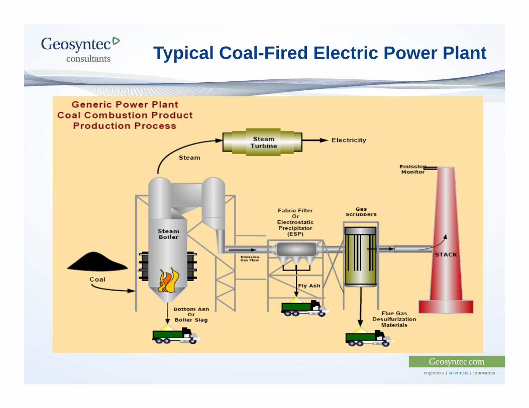
Typical Coal-Fired Electric Power Plant
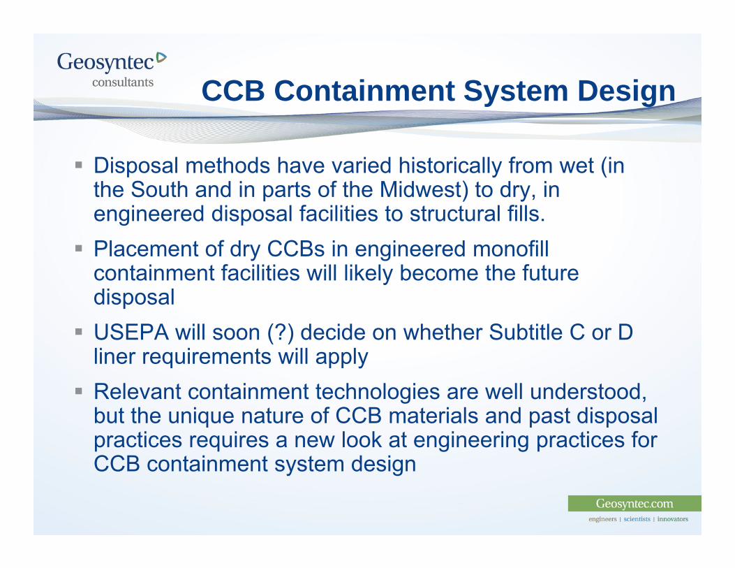
CCB Containment System Design
Disposal methods have varied historically from wet (in the South and in parts of the Midwest) to dry, in engineered disposal facilities to structural fills.
Placement of dry CCBs in engineered monofillcontainment facilities will likely become the future disposal
USEPA will soon (?) decide on whether Subtitle C or D liner requirements will apply
Relevant containment technologies are well understood, but the unique nature of CCB materials and past disposal practices requires a new look at engineering practices for CCB containment system design
Current State of the Practice
New CCB disposal facilities (i.e.thoseconstructed between 1994-2004)generally have liner systems
Hundreds of existing CCB disposalfacilities have no liner systems
Many of these sites are candidates forvertical/lateral expansions
Lack of data on existing facilities maylimit ability to expand – but why?
Reference: U.S. Environmental Protection Agency and U.S. Department of theEnergy “Coal Combustion Waste Management at Landfills and SurfaceImpoundments”, 1994-2004, DOE/PI-0004, [2006].
Key Design Issues – Outline
CCB and Fly Ash PropertiesFoundation Stability Settlement Slope Stability Seismic Liquefaction Static Liquefaction
Leachate Collections SystemsPerformance Assessment of Existing CCR landfills
Characterization of CCBs
CCBs generally well characterized from historical studies, primarily viewing from beneficial reuse applications
Behavior of in-situ materials is not well understood, nor is this information widely published There is a need to assess this on a site-by-site basis Unique characteristics of CCBs add to the technical challenge of
this study (i.e., size, shape, Gs, mineralogy, etc.)
Experience has show consistency and has shed light on the subject, but only recently presented in comprehensive format Much of the information is recent Much, but not all of it, is available in the literature
What’s So Different About Fly Ash?
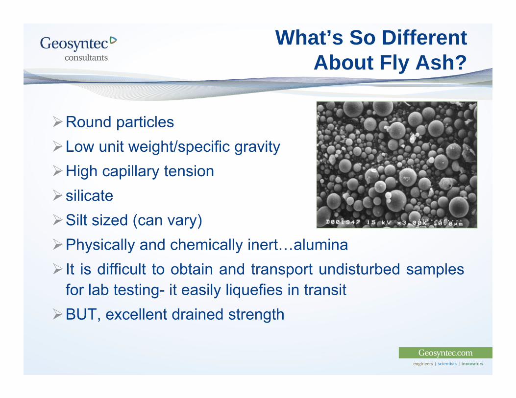
Round particlesLow unit weight/specific gravityHigh capillary tensionsilicateSilt sized (can vary)Physically and chemically inert…alumina It is difficult to obtain and transport undisturbed samples
for lab testing- it easily liquefies in transitBUT, excellent drained strength
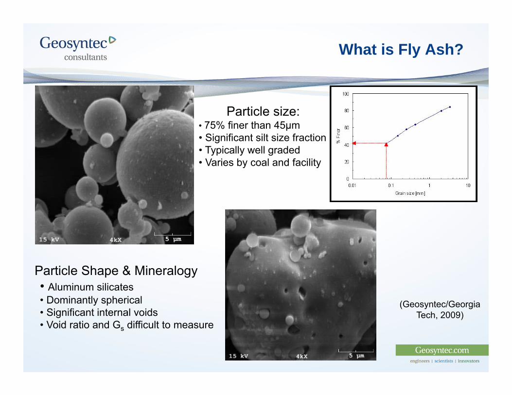
What is Fly Ash?
Particle Shape & Mineralogy• Aluminum silicates • Dominantly spherical • Significant internal voids• Void ratio and Gs difficult to measure
Particle size:• 75% finer than 45μm• Significant silt size fraction• Typically well graded• Varies by coal and facility
(Geosyntec/Georgia Tech, 2009)
Challenges Associated With Closure of Impoundments
Limited accurate information available regarding fly ash material properties Low CPT tip resistance can be misleading and cause undue
concerns regarding strength Even Class F ash has been shown to “age” with time when
confined Key element is control of water (infiltration and internal
drainage)
Each facility will have unique conditions based on material properties, construction methodology, operational history, and facility layout
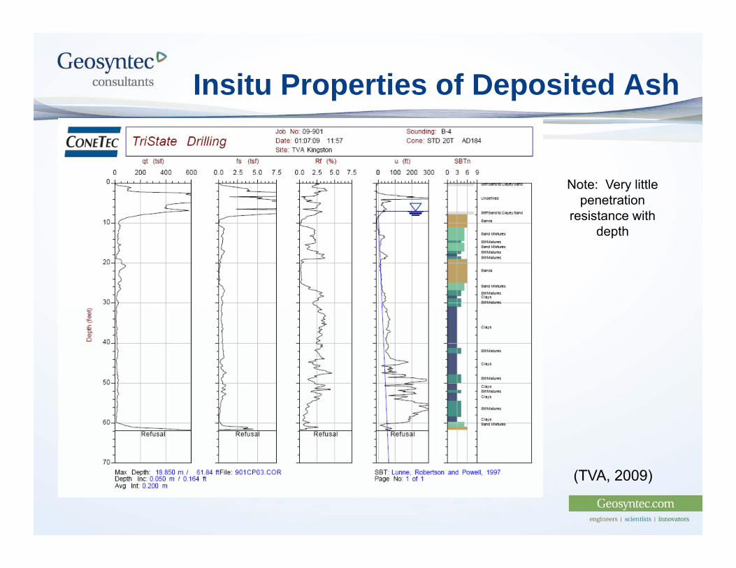
Insitu Properties of Deposited Ash
Note: Very littlepenetration
resistance withdepth
(TVA, 2009)
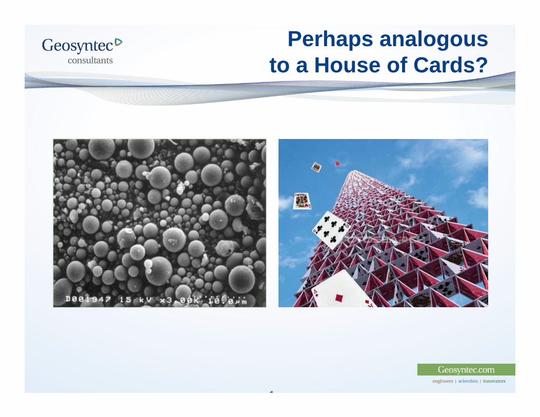
Perhaps analogous to a House of Cards?
1
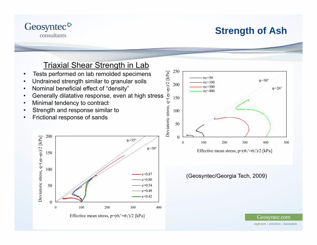
Strength of Ash
0
50
100
150
200
0 100 200 300 400
Effective mean stress, p=(σ1'+σ3')/2 [kPa]
Dev
iato
ric s
tress
, q=(
σ1-
σ3)/2
[kPa
]
e=0.87e=0.80e=0.54e=0.48e=0.42
φ=30°
φ=35°0
50
100
150
200
250
0 100 200 300 400 500
Effective mean stress, p=(σ1'+σ3')/2 [kPa]
Dev
iato
ric s
tress
, q=(
σ1-
σ3)/2
[kPa
]
σc=50σc=100σc=300σc=400Series1Series2
φ=30°
φ=26°
Triaxial Shear Strength in Lab• Tests performed on lab remolded specimens • Undrained strength similar to granular soils• Nominal beneficial effect of “density”• Generally dilatative response, even at high stress• Minimal tendency to contract• Strength and response similar to• Frictional response of sands
(Geosyntec/Georgia Tech, 2009)
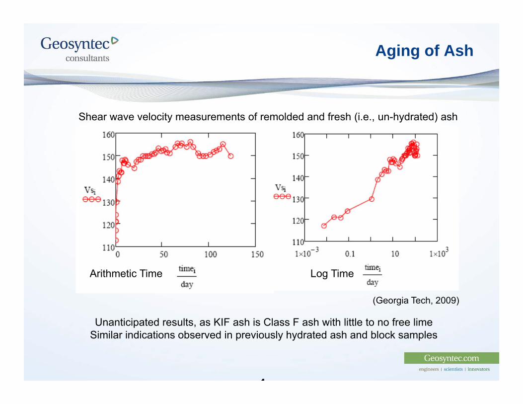
Aging of Ash
1
Shear wave velocity measurements of remolded and fresh (i.e., un-hydrated) ash
Arithmetic Time Log Time
Unanticipated results, as KIF ash is Class F ash with little to no free limeSimilar indications observed in previously hydrated ash and block samples
(Georgia Tech, 2009)
Fly Ash Characterization: Implications to Closure and Overfill Practice
We have a good understanding of fly ash and CCB properties
Fly ash properties vary from site to site, and can vary within a site, as a function of many factors (coal source, combustion process, air pollution controls, disposal method, disposal site operations, etc.)
These materials are not typical geotechnical construction materials and need to be well understood to characterize a site correctly and develop a good design
1
Foundation Stability
Settlement
Calculations are sensitive to material properties and canvary widely
Settlement can be in the range of 10% of total thicknessof fly ash (Class F) pond based on experience at foursites
How Can The Accuracy Of Settlement Estimates Be Improved?
1. Specialized Undisturbed Sampling
2. In Situ and Lab Testing
3. Field Tests: Monitored Preload Fill-PilotTest
Monitored Preload Fill
A MPF provides a method to verify engineering calculations bymeasuring settlements on a pilot scale.
It’s a large pilot scale test and relatively expensive so it must be afall back solution to convince regulatory agencies
Test measurements require redundancy
It’s possible that, after a period of MPF performance and publication,the practice and regulators will depend on preload fill demonstrationsless and less
Monitored Preload Fill
Consists of application of load (soil layers) in incrementsand measurement of:
Settlement/deflection of the surface and subsurface layers
Pore pressures in the subsurface layers
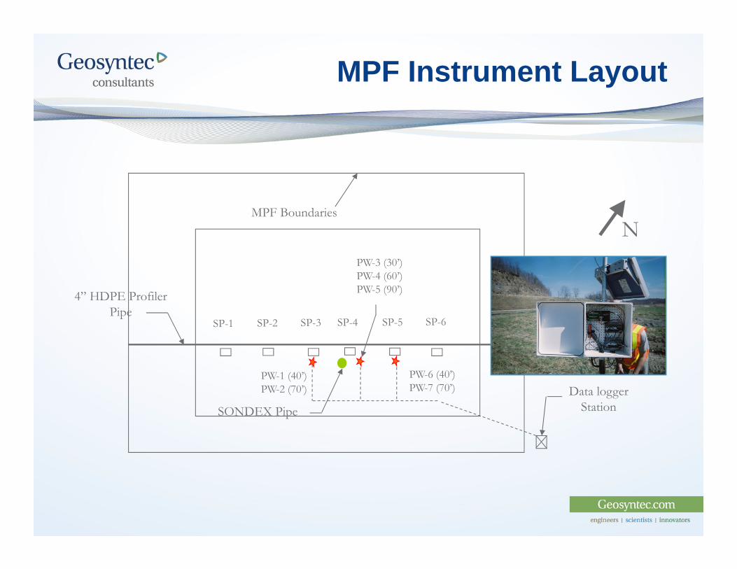
MPF Instrument Layout
Data logger Station
SP-1 SP-5SP-4 SP-6SP-2 SP-3
4” HDPE Profiler Pipe
PW-6 (40’)PW-7 (70’)
PW-1 (40’)PW-2 (70’)
PW-3 (30’)PW-4 (60’)PW-5 (90’)
SONDEX Pipe
MPF BoundariesN
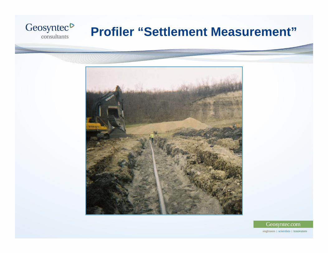
Profiler “Settlement Measurement”
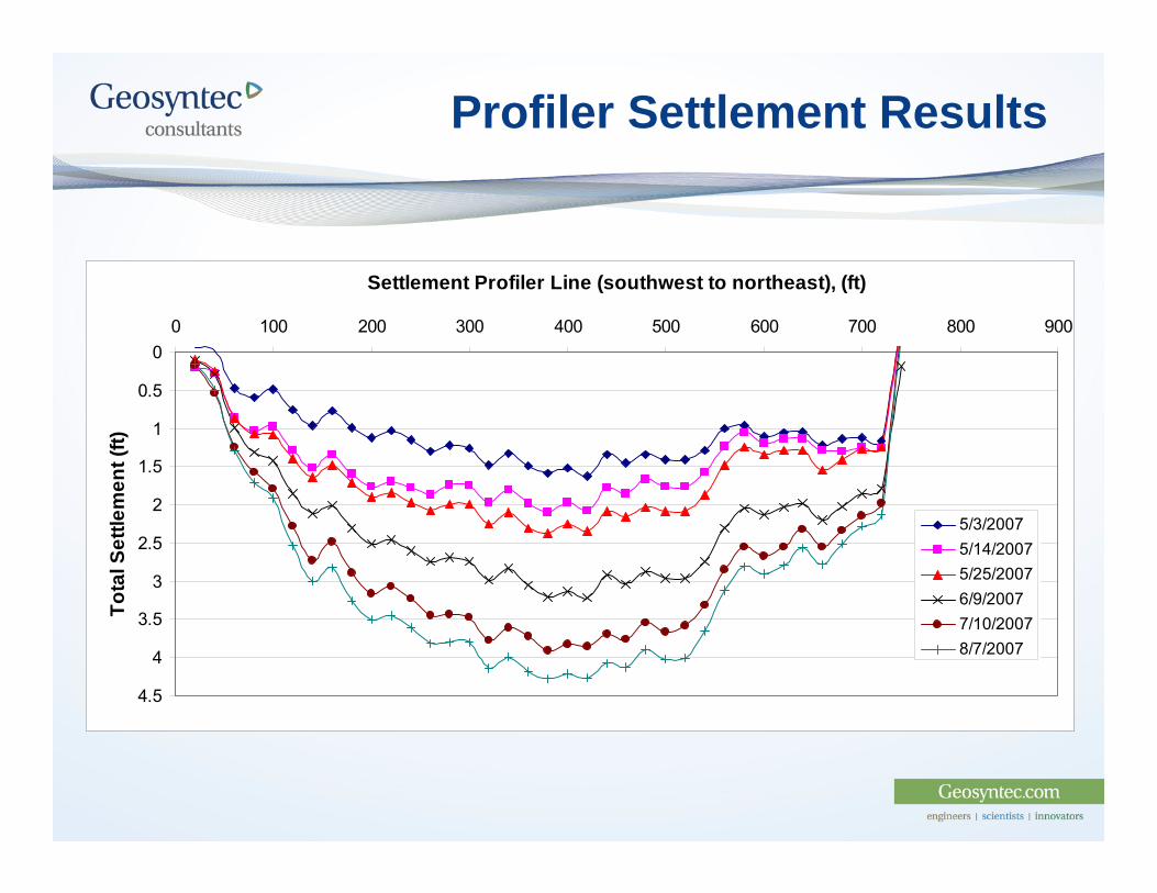
Profiler Settlement Results
0
0.5
1
1.5
2
2.5
3
3.5
4
4.5
0 100 200 300 400 500 600 700 800 900
Settlement Profiler Line (southwest to northeast), (ft)
Tota
l Set
tlem
ent (
ft)
5/3/20075/14/20075/25/20076/9/20077/10/20078/7/2007
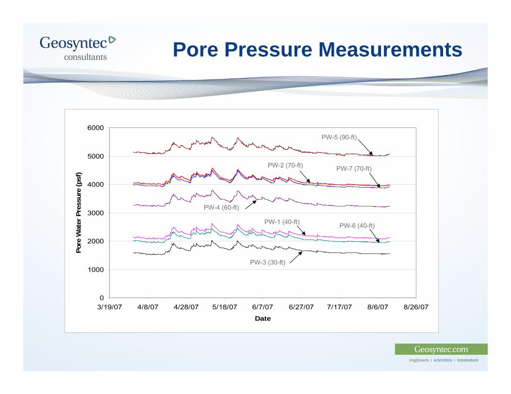
Pore Pressure Measurements
0
1000
2000
3000
4000
5000
6000
3/19/07 4/8/07 4/28/07 5/18/07 6/7/07 6/27/07 7/17/07 8/6/07 8/26/07
Date
Pore
Wat
er P
ress
ure
(psf
)
PW-6 (40-ft)
PW-5 (90-ft)
PW-4 (60-ft)
PW-1 (40-ft)
PW-3 (30-ft)
PW-2 (70-ft) PW-7 (70-ft)
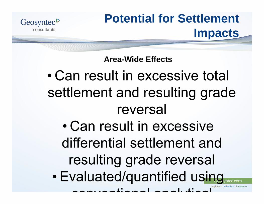
Potential for Settlement Impacts
Area-Wide Effects
• Can result in excessive total settlement and resulting grade
reversal• Can result in excessive differential settlement and resulting grade reversal
• Evaluated/quantified using conventional analytical
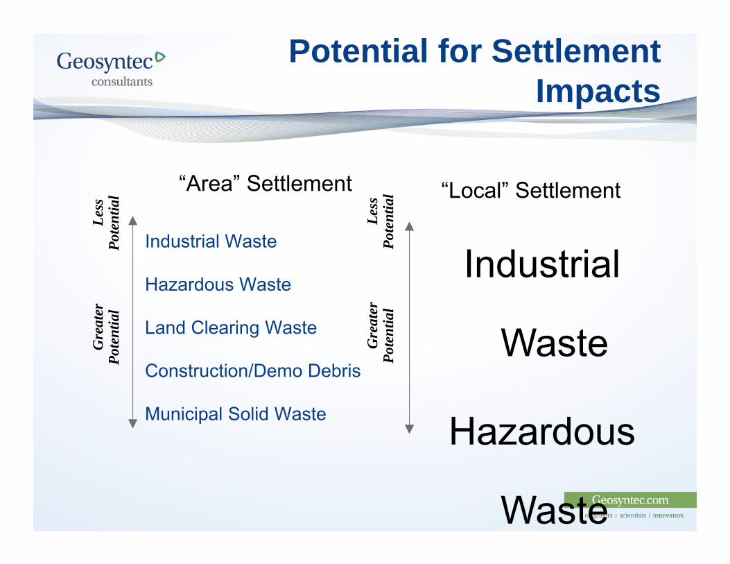
Potential for Settlement Impacts
Industrial Waste
Hazardous Waste
Land Clearing Waste
Construction/Demo Debris
Municipal Solid Waste
Gre
ater
Le
ssPo
tent
ial
Pot
entia
l “Area” Settlement “Local” Settlement
Industrial
Waste
Hazardous
Waste
Gre
ater
Le
ssPo
tent
ial
Pot
entia
l
Key Design Issues
Foundation Stability Settlement Slope Stability Seismic Liquefaction Static Liquefaction
Leachate Collections SystemsPerformance Assessment of Existing CCR landfill
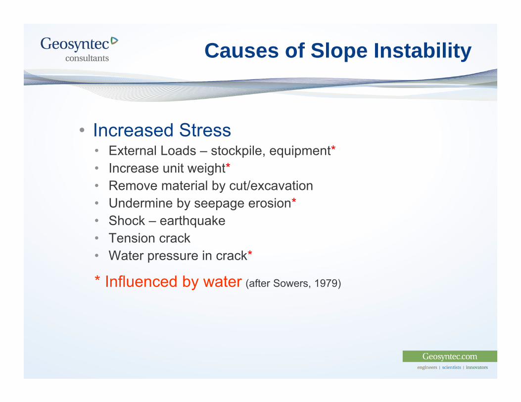
Causes of Slope Instability
• Increased Stress• External Loads – stockpile, equipment*• Increase unit weight*• Remove material by cut/excavation• Undermine by seepage erosion*• Shock – earthquake• Tension crack• Water pressure in crack*
* Influenced by water (after Sowers, 1979)
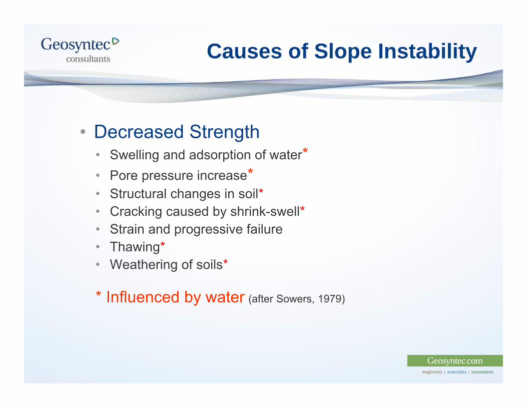
Causes of Slope Instability
• Decreased Strength• Swelling and adsorption of water*• Pore pressure increase*• Structural changes in soil*• Cracking caused by shrink-swell*• Strain and progressive failure• Thawing*• Weathering of soils*
* Influenced by water (after Sowers, 1979)
Key Design Issues
Foundation Stability Settlement Slope Stability Seismic Liquefaction Static Liquefaction
Leachate Collections SystemsPerformance Assessment of Existing CCR landfill
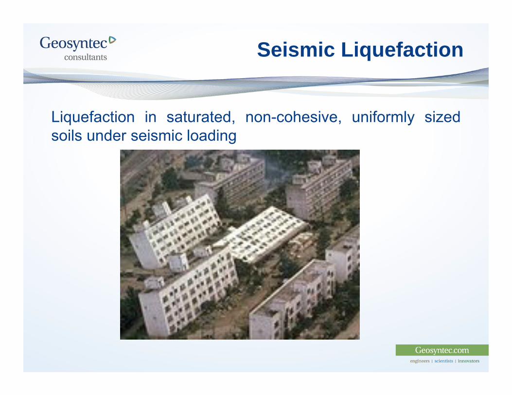
Seismic Liquefaction
Liquefaction in saturated, non-cohesive, uniformly sizedsoils under seismic loading
Seismic Liquefaction
The prevention of seismic liquefaction requires expensive mitigationmethods: Construction of a toe berm (soil embankment) or buttress beyond the
edge of the landfill to maintain confinement of the subgrade; Installation of a shear key at the edge of the landfill to resist the lateral
movements below the edge of the landfill; Performing a preload fill program to promote consolidation and reduce
liquefaction potential or reduce the effects of liquefaction, should it occur; and
Foundation improvements such as deep soil mixing and solidification to improve the subgrade.
Additional Study is necessary using laboratory cyclic triaxial and/or directsimple shear testing correlated to the project setting
Preliminary laboratory data suggest that the risk of seismically-inducedliquefaction using the traditional analytical methods is over estimated
Static Liquefaction
Caused by relatively rapid loading of the subgrade that causesstrain-induced excess pore pressures that cannot beadequately dissipated resulting in a bearing-capacity typefailure
Can be analyzed during design and avoided by constructionmethods
Recent lab testing is finding it difficult to induce staticliquefaction
Key Design Issues
Foundation Stability Settlement Slope Stability Seismic Liquefaction Static Liquefaction
Leachate Collections SystemsPerformance Assessment of Existing CCR landfill
Leachate Collection Systems
Decreases in functionality caused by:
Settlement-induced grade changes in LCS components
Clogging by fine particles and calcification
Overloading of existing leachate collection systems under existinglandfills
Addressed during design through testing and design ofexcess filtration capacity
Leachate Collection Systems
To prevent clogging, landfill LCS layers are typically overlain by a geotextile filterlayer, which must have a relatively small apparent opening size (AOS) to prevent theCCR material from passing through the geotextile.
Large overburden pressures caused by the overlying CCR can reduce theeffectiveness of a geotextile filter.
To address these design challenges:(i) perform a particle-size analysis of the CCR material to confirm the properties of
the material that the geotextile must retain;(ii) test the geotextile filter under the expected overburden pressures to assess its
filtration properties;(iii) provide excess filtration layer surface area over/around the collection/drainage
gravel as a contingency in case the geotextile filter experiences some clogging;and
(iv) provide a method of cleaning out the leachate collection and transmission pipesshould precipitates form or sediments accumulate that could reduce pipeconveyance capacity
Key Design Issues
Foundation Stability Settlement Slope Stability Seismic Liquefaction Static Liquefaction
Leachate Collections SystemsPerformance Assessment of Existing CCR landfill
Performance Assessment of Existing Facility
Evaluate During Expansion Design:
Landfill Liner System
Older design standard
May not allow vertical expansion
Leachate Collection System
Piping may not allow vertical expansion
Case Histories
CASE HISTORY ONE:
Vertical Expansion Over Closed CCR Pond
CASE HISTORY TWO:
Lateral Expansion and Overfill on CCR Landfill
CASE HISTORY THREE:
Overfill and Lateral Expansion on CCR Landfill and Pond
Case History #1 – Vertical Expansion Over Closed CCR Pond
1. 110-acre Ash Pond Subgrade
2. 35 m of Mostly Saturated Fly Ash Subgrade
3. Class I High Hazard Dam Downstream
4. Lateral Groundwater Inflow
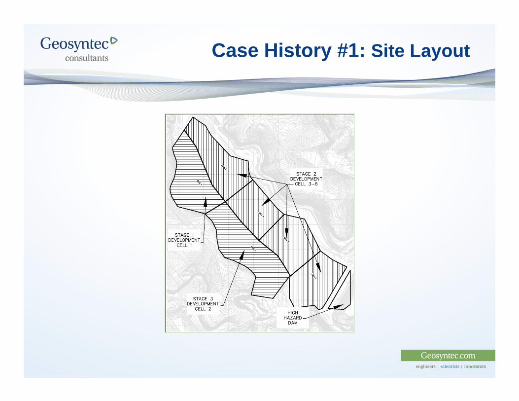
Case History #1: Site Layout
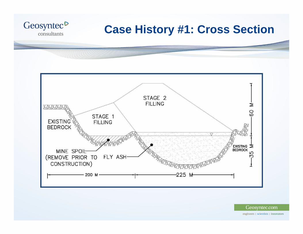
Case History #1: Cross Section
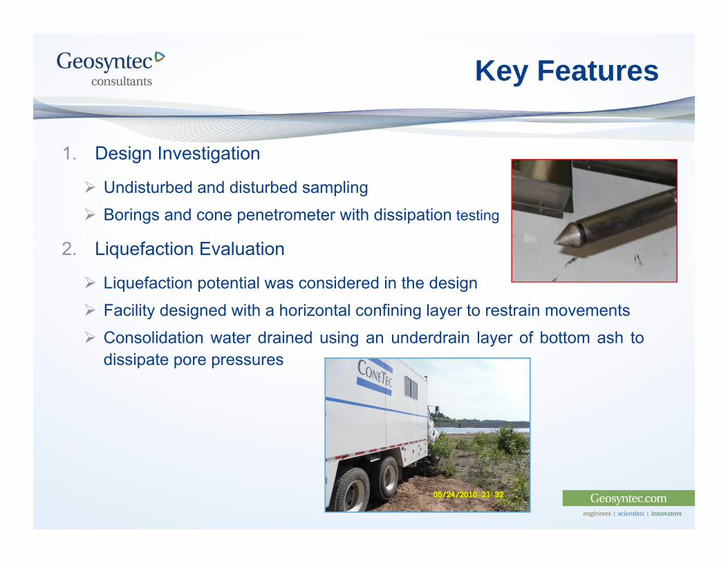
Key Features
1. Design Investigation
Undisturbed and disturbed sampling Borings and cone penetrometer with dissipation testing
2. Liquefaction Evaluation
Liquefaction potential was considered in the design Facility designed with a horizontal confining layer to restrain movements Consolidation water drained using an underdrain layer of bottom ash to
dissipate pore pressures
Key Features
3. Hydrostatic Uplift Potential- Lateral Groundwater Inflow
Mitigated using Bottom Ash Underdrain below Liner to Dissipate PorePressures
Mitigated using Sand Underdrain on Side Slopes
4. Settlement Evaluation
Mitigated using a Moving Preload to Remove Significant Settlementbefore Construction
Lateral Expansion and Overfill Key Features
1. Significant site geometry constraints
2. Desire to construct expansion in small increments
3. Utilize the existing footprint as much as practical
Hydrostatic Uplift
Engineering Issues High groundwater table and increased pore pressures in fly ash
pond during construction and filling Groundwater seepage pressures along high wall after construction
Engineering Solutions Side slope drainage blanket of 60-cm thick granular material
below isolation layer Groundwater under drain of 60-cm thick granular material below
isolation layer
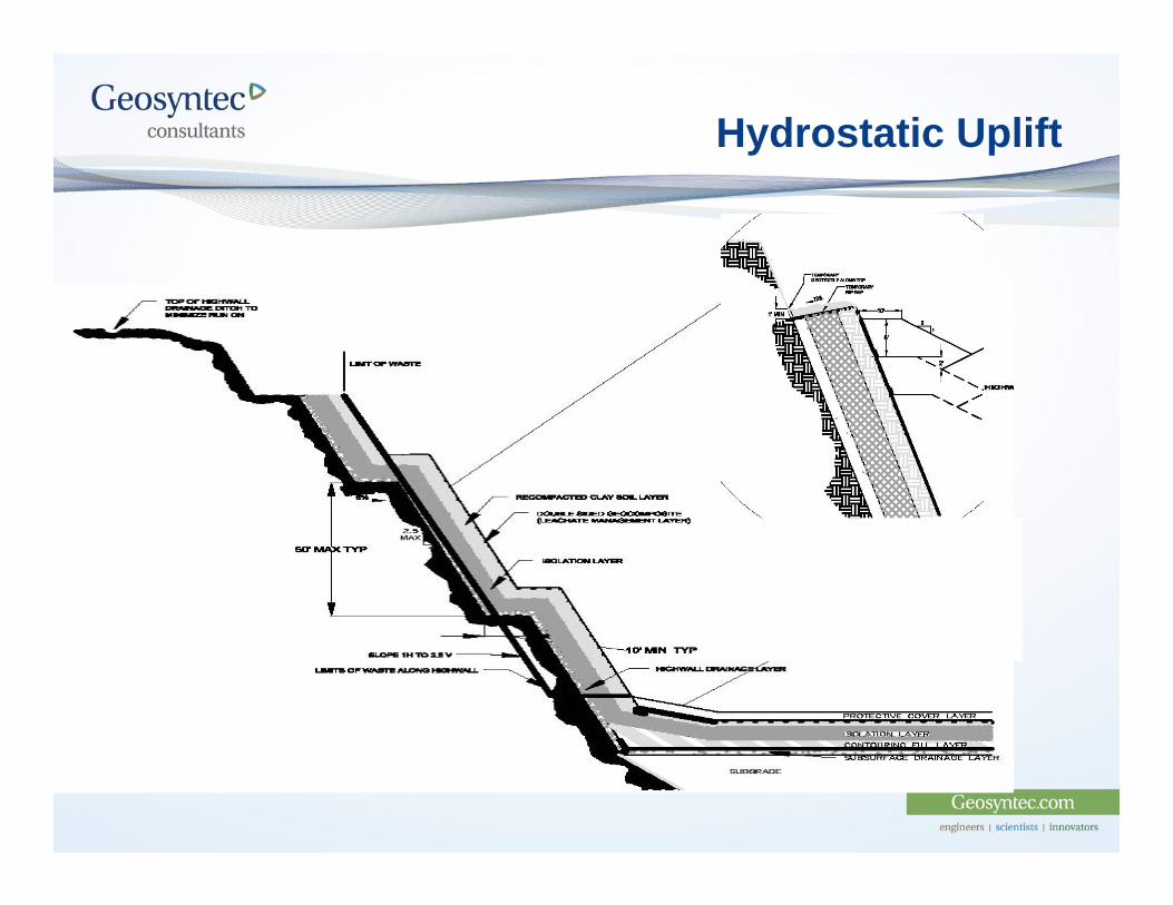
Hydrostatic Uplift
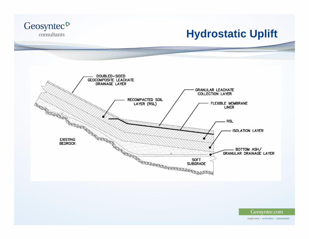
Hydrostatic Uplift
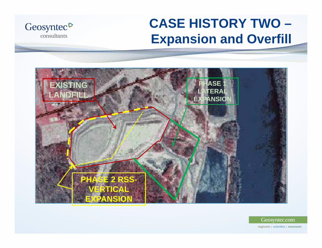
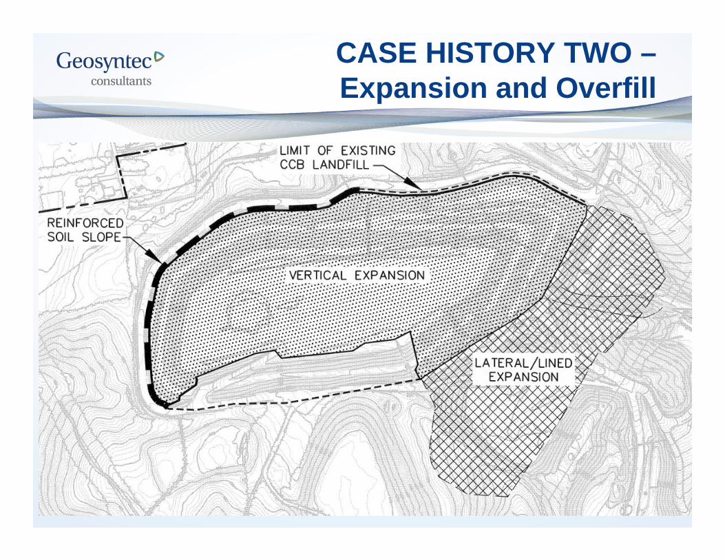
CASE HISTORY TWO –Expansion and Overfill
EXISTING LANDFILL
PHASE 1 LATERAL
EXPANSION
PHASE 2 RSS-VERTICAL
EXPANSION
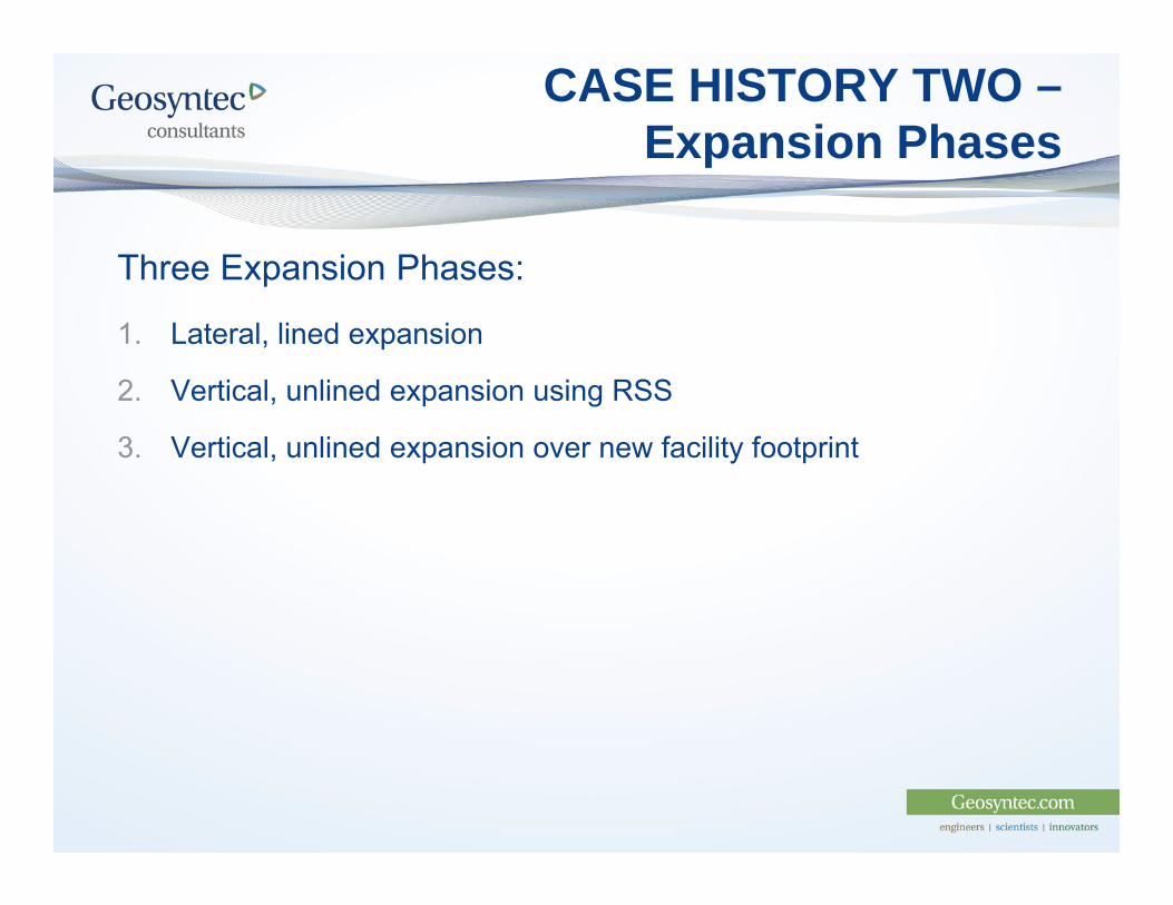
CASE HISTORY TWO –Expansion Phases
Three Expansion Phases:
1. Lateral, lined expansion
2. Vertical, unlined expansion using RSS
3. Vertical, unlined expansion over new facility footprint
CASE HISTORY TWO –Expansion and Overfill
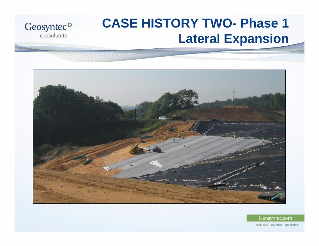
CASE HISTORY TWO- Phase 1 Lateral Expansion
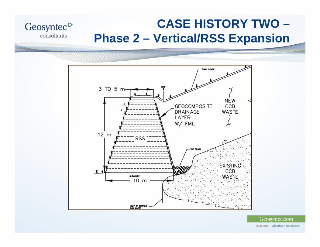
CASE HISTORY TWO –Phase 2 – Vertical/RSS Expansion
CASE HISTORY TWO –Phase 3 – Vertical Expansion
Stay tuned to this station!
CASE HISTORY THREE – Overfill and Lateral Expansion Key Features
1. Existing 250 acre CCR landfill
2. A 50,000,000 yd3 expansion needed
3. Adjacent to a 300-acre inactive (not closed) ash pond
CASE HISTORY THREE –Development Considerations
1. Utilize the existing footprint as much as practical
2. Expand laterally over ash pond
3. Significant site geometry constraints
4. Significant mine voids below edge of footprint
CASE HISTORY THREE
1. Site characterization of ash in the pond using boringsand CPTu probes
2. Specialized evaluation of existing LCS pipes plus videoinspection
3. Geometry constraints overcome through excavation andincreasing vertical expansion
4. Mine voids mitigated primarily by excavation
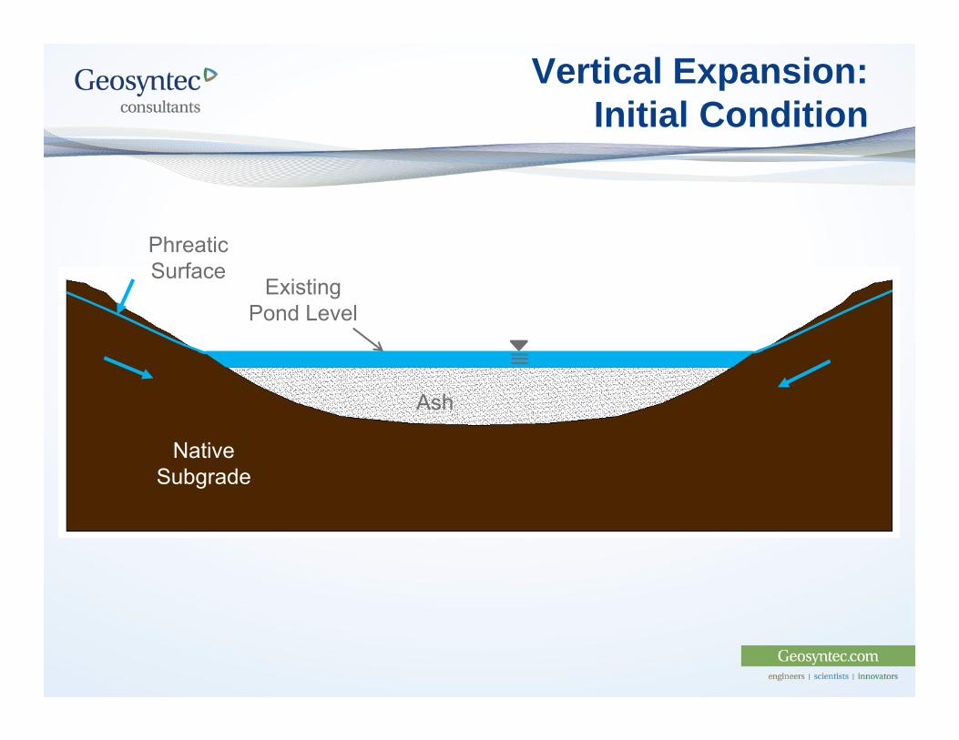
Vertical Expansion: Initial Condition
Ash
Native Subgrade
Existing Pond Level
Phreatic Surface
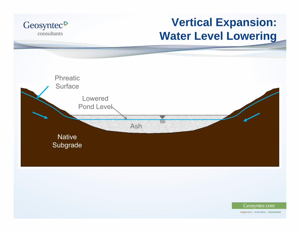
Vertical Expansion: Water Level Lowering
AshNative
Subgrade
Lowered Pond Level
Phreatic Surface
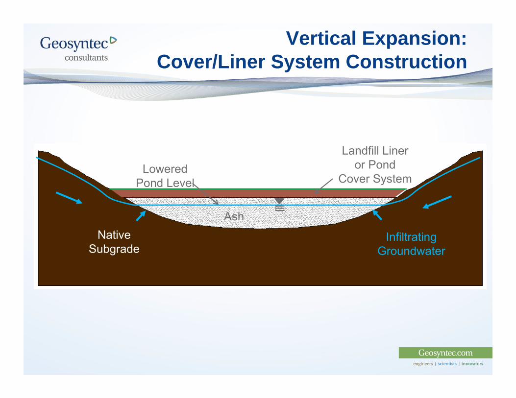
Vertical Expansion: Cover/Liner System Construction
AshNative
Subgrade
Landfill Liner or Pond
Cover SystemLowered
Pond Level
Infiltrating Groundwater
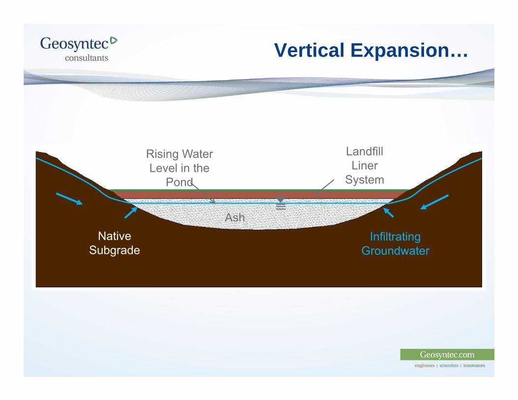
Vertical Expansion…
AshNative
Subgrade
Landfill Liner
System
Infiltrating Groundwater
Rising Water Level in the
Pond
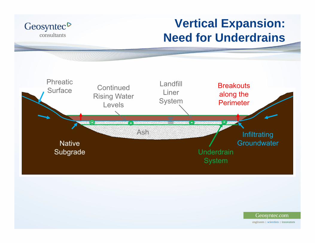
Vertical Expansion: Need for Underdrains
AshNative
Subgrade
Landfill Liner
System
Infiltrating Groundwater
Breakouts along the Perimeter
Continued Rising Water
Levels
Phreatic Surface
UnderdrainSystem
Case Study 3: Observations
1. Need to accurately identify geology/subgrade
2. Assess structural integrity of as-built existing LCS
3. Understand the long-term groundwater pore pressureconditions in ash/subgrade and be prepared to designunderdrain system for groundwater as “leachate”
Conclusions
1. Development over the top of an existing CCR pond andlandfill is possible and has been completedsuccessfully.
2. The design should have investigation and testing datafrom multiple sources such as CPTu, nominallyundisturbed samples (which are difficult to obtain) forlaboratory testing, perhaps even using a monitoredpreload fill to confirm calculated settlements and porepressure dissipation, especially when developing over aCCR pond where it is difficult to obtain undisturbedsamples.
Conclusions
3. In the authors’ experience, the time required todissipate pore pressures in the CCR after filling canoften be dissipated within the timeframe of normaloperations of disposal facility.
4. A CCR disposal facility can be designed to mitigate theeffects of seismic and/or static liquefaction.
Recommendations
1. Conduct a pre-design investigation to verify the CCRcharacteristics and their potential impact on design andassess the economic viability of the site.
2. Site specific, field, and laboratory characterizations ofCCR materials are necessary for the engineeringanalyses to accurately predict settlement of the overfillliner system.
3. Conduct site specific testing to evaluate liquefaction ofCCRs.
Recommendations
4. Develop a plan to manage groundwater and saturatedCCRs below the landfill to avoid buildup of porepressures that could lead to foundation instability.
5. For overfills, conduct a thorough evaluation of theexisting landfill leachate collection system and linerstability to verify that the LCS will can function under theincreased pressures resulting from the overfill CCRmaterials.
Acknowledgements
1. Contributing Clients: American Electric Power Allegheny Energy Supply/First Energy TVA
2. Co-workers/contributors: John Seymour, P.E., Paul Sabatini, Ph.D., P.E.; Dan Bodine,
P.E.; Burak Tanyu, Ph.D.; William Steier, P.E.; Rodolfo Sancio,Ph.D.; John Esser, P.E.
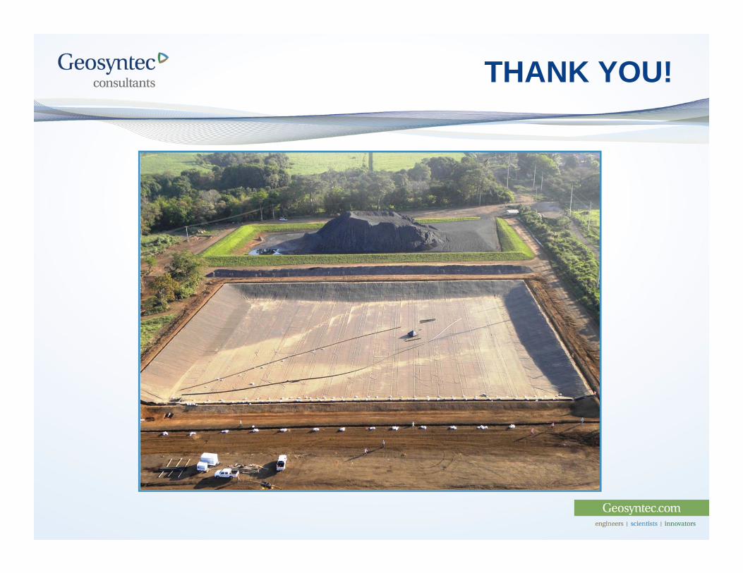
THANK YOU!