Embed Size (px)
Citation preview
09-0
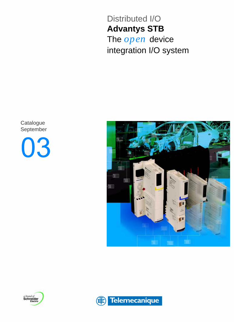
3 Distributed I/OAdvantys STBThe open device integration I/O system
Catalogue September
Dis
trib
uted
I/O
Adv
anty
s S
TB
www.schneider-electric.com
September 2003
Schneider Electric Industries SAS
DIA
6ED
2030
901E
N -
© 2
003
Sch
neid
er E
lect
ric -
All
right
s re
serv
ed
ART. 061231
Tel
emec
aniq
ue
1
Contents Advantys STBDistributed I/O Solution 1
Open and modular system b Presentation, description . . . . . . . . . . . . . . . . . . . . . . . . . . . . . . . . . . pages 2 to 4
b References, dimensions . . . . . . . . . . . . . . . . . . . . . . . . . . . . . . . . . . . . . . . page 5
Network interface modulesSelection guide . . . . . . . . . . . . . . . . . . . . . . . . . . . . . . . . . . . . . . . . pages 6 and 7
b Presentation, description, characteristics . . . . . . . . . . . . . . . . . . . . pages 8 to 10
b References, dimensions . . . . . . . . . . . . . . . . . . . . . . . . . . . . . . . . pages 11 to 13
Power distribution modulesb Presentation, description, characteristics . . . . . . . . . . . . . . . . . . . . . . . . . page 14
b References, dimensions . . . . . . . . . . . . . . . . . . . . . . . . . . . . . . . . . . . . . . page 15
Digital input/output modulesSelection guide . . . . . . . . . . . . . . . . . . . . . . . . . . . . . . . . . . . . . . pages 16 and 17
b Presentation, description, characteristics . . . . . . . . . . . . . . . . . . . pages 18 to 21
b References, dimensions . . . . . . . . . . . . . . . . . . . . . . . . . . . . . . . pages 22 and 23
b Wiring . . . . . . . . . . . . . . . . . . . . . . . . . . . . . . . . . . . . . . . . . . . . . . pages 23 to 25
Analog input/output modulesSelection guide . . . . . . . . . . . . . . . . . . . . . . . . . . . . . . . . . . . . . . pages 26 and 27
b Presentation, description, characteristics . . . . . . . . . . . . . . . . . . . pages 28 to 30
b References, dimensions . . . . . . . . . . . . . . . . . . . . . . . . . . . . . . . . . . . . . . page 31
b Wiring . . . . . . . . . . . . . . . . . . . . . . . . . . . . . . . . . . . . . . . . . . . . . pages 32 and 33
Application-specificb Parallel interface for Tego Power applications . . . . . . . . . . . . . . pages 34 and 35
b Parallel interface for TeSys model U applications . . . . . . . . . . . . pages 36 and 37
b Counter module
v Presentation, description, characteristics . . . . . . . . . . . . . . . . . pages 38 to 40
v References, dimensions, wiring . . . . . . . . . . . . . . . . . . . . . . . . . . . . . . . page 41
Configuration softwareb Advantys configuration software . . . . . . . . . . . . . . . . . . . . . . . . . . pages 42 to 45
Phaseo regulated power suppliesb Presentation, characteristics . . . . . . . . . . . . . . . . . . . . . . . . . . . . pages 46 to 50
b Association, references, dimensions . . . . . . . . . . . . . . . . . . . . . . . . . . . . . page 51
Servicesb Automation product certifications . . . . . . . . . . . . . . . . . . . . . . . . pages 52 and 53
b Power requirements . . . . . . . . . . . . . . . . . . . . . . . . . . . . . . . . . . . . . . . . . page 54
b Community regulations and protective treatment . . . . . . . . . . . . . . . . . . . page 55
b Product reference index . . . . . . . . . . . . . . . . . . . . . . . . . . . . . . . . . . . . . . page 56
2
Presentation,composition
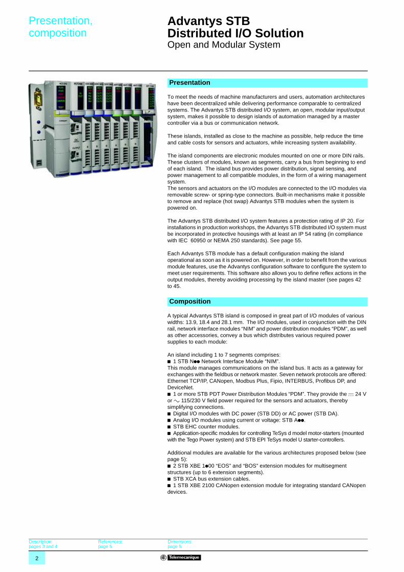
Advantys STB Distributed I/O Solution 1
Open and Modular System
To meet the needs of machine manufacturers and users, automation architectures have been decentralized while delivering performance comparable to centralized systems. The Advantys STB distributed I/O system, an open, modular input/output system, makes it possible to design islands of automation managed by a master controller via a bus or communication network.
These islands, installed as close to the machine as possible, help reduce the time and cable costs for sensors and actuators, while increasing system availability.
The island components are electronic modules mounted on one or more DIN rails. These clusters of modules, known as segments, carry a bus from beginning to end of each island. The island bus provides power distribution, signal sensing, and power management to all compatible modules, in the form of a wiring management system.The sensors and actuators on the I/O modules are connected to the I/O modules via removable screw- or spring-type connectors. Built-in mechanisms make it possible to remove and replace (hot swap) Advantys STB modules when the system is powered on.
The Advantys STB distributed I/O system features a protection rating of IP 20. For installations in production workshops, the Advantys STB distributed I/O system must be incorporated in protective housings with at least an IP 54 rating (in compliance with IEC 60950 or NEMA 250 standards). See page 55.
Each Advantys STB module has a default configuration making the island operational as soon as it is powered on. However, in order to benefit from the various module features, use the Advantys configuration software to configure the system to meet user requirements. This software also allows you to define reflex actions in the output modules, thereby avoiding processing by the island master (see pages 42 to 45.
A typical Advantys STB island is composed in great part of I/O modules of various widths: 13.9, 18.4 and 28.1 mm. The I/O modules, used in conjunction with the DIN rail, network interface modules “NIM” and power distribution modules “PDM”, as well as other accessories, convey a bus which distributes various required power supplies to each module:
An island including 1 to 7 segments comprises:b 1 STB Npp Network Interface Module “NIM”. This module manages communications on the island bus. It acts as a gateway for exchanges with the fieldbus or network master. Seven network protocols are offered: Ethernet TCP/IP, CANopen, Modbus Plus, Fipio, INTERBUS, Profibus DP, and DeviceNet.b 1 or more STB PDT Power Distribution Modules “PDM”. They provide the c 24 V or a 115/230 V field power required for the sensors and actuators, thereby simplifying connections.b Digital I/O modules with DC power (STB DD) or AC power (STB DA).b Analog I/O modules using current or voltage: STB App.b STB EHC counter modules.b Application-specific modules for controlling TeSys d model motor-starters (mounted with the Tego Power system) and STB EPI TeSys model U starter-controllers.
Additional modules are available for the various architectures proposed below (see page 5):b 2 STB XBE 1p00 “EOS” and “BOS” extension modules for multisegment structures (up to 6 extension segments).b STB XCA bus extension cables.b 1 STB XBE 2100 CANopen extension module for integrating standard CANopen devices.
Presentation
Composition
Description:pages 3 and 4
References:page 5
Dimensions:page 5
3
Description Advantys STB Distributed I/O Solution 1
Open and Modular System
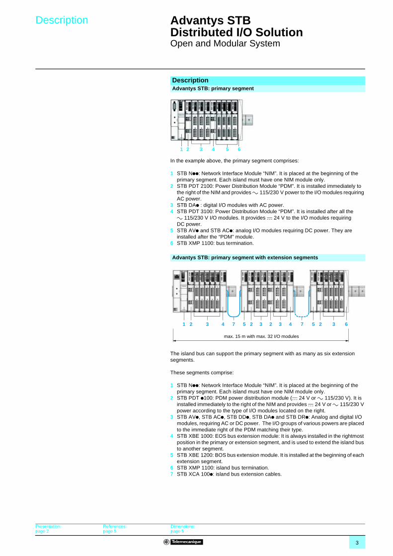
In the example above, the primary segment comprises:
1 STB Npp: Network Interface Module “NIM”. It is placed at the beginning of the primary segment. Each island must have one NIM module only.
2 STB PDT 2100: Power Distribution Module “PDM”. It is installed immediately to the right of the NIM and provides a 115/230 V power to the I/O modules requiring AC power.
3 STB DAp : digital I/O modules with AC power.4 STB PDT 3100: Power Distribution Module “PDM”. It is installed after all the
a 115/230 V I/O modules. It provides c 24 V to the I/O modules requiring DC power.
5 STB AVp and STB ACp: analog I/O modules requiring DC power. They are installed after the “PDM” module.
6 STB XMP 1100: bus termination.
The island bus can support the primary segment with as many as six extension segments.
These segments comprise:
1 STB Npp: Network Interface Module “NIM”. It is placed at the beginning of the primary segment. Each island must have one NIM module only.
2 STB PDT p100: PDM power distribution module (c 24 V or a 115/230 V). It is installed immediately to the right of the NIM and provides c 24 V or a 115/230 V power according to the type of I/O modules located on the right.
3 STB AVp, STB ACp, STB DDp, STB DAp and STB DRp: Analog and digital I/O modules, requiring AC or DC power. The I/O groups of various powers are placed to the immediate right of the PDM matching their type.
4 STB XBE 1000: EOS bus extension module: It is always installed in the rightmost position in the primary or extension segment, and is used to extend the island bus to another segment.
5 STB XBE 1200: BOS bus extension module. It is installed at the beginning of each extension segment.
6 STB XMP 1100: island bus termination.7 STB XCA 100p: island bus extension cables.
DescriptionAdvantys STB: primary segment
1 2 3 4 5 6
Advantys STB: primary segment with extension segments
1 2 5 2 5 2 623 33 34 47 7
max. 15 m with max. 32 I/O modules
Presentation:page 2
References:page 5
Dimensions:page 5
4
Description (continued) Advantys STB Distributed I/O Solution 1
Open and Modular System
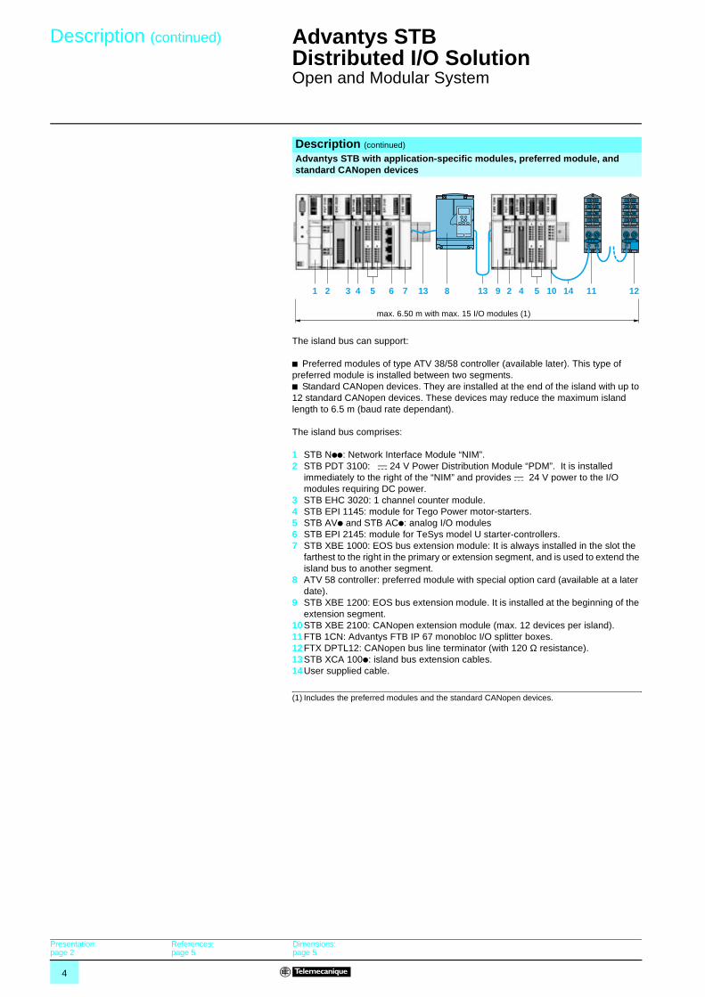
The island bus can support:
b Preferred modules of type ATV 38/58 controller (available later). This type of preferred module is installed between two segments.b Standard CANopen devices. They are installed at the end of the island with up to 12 standard CANopen devices. These devices may reduce the maximum island length to 6.5 m (baud rate dependant).
The island bus comprises:
1 STB Npp: Network Interface Module “NIM”.2 STB PDT 3100: c 24 V Power Distribution Module “PDM”. It is installed
immediately to the right of the “NIM” and provides c 24 V power to the I/O modules requiring DC power.
3 STB EHC 3020: 1 channel counter module.4 STB EPI 1145: module for Tego Power motor-starters.5 STB AVp and STB ACp: analog I/O modules6 STB EPI 2145: module for TeSys model U starter-controllers.7 STB XBE 1000: EOS bus extension module: It is always installed in the slot the
farthest to the right in the primary or extension segment, and is used to extend the island bus to another segment.
8 ATV 58 controller: preferred module with special option card (available at a later date).
9 STB XBE 1200: EOS bus extension module. It is installed at the beginning of the extension segment.
10STB XBE 2100: CANopen extension module (max. 12 devices per island).11FTB 1CN: Advantys FTB IP 67 monobloc I/O splitter boxes.12FTX DPTL12: CANopen bus line terminator (with 120 Ω resistance). 13STB XCA 100p: island bus extension cables.14User supplied cable.
(1) Includes the preferred modules and the standard CANopen devices.
Description (continued)
Advantys STB with application-specific modules, preferred module, and standard CANopen devices
1 2 23 13 86 7 10 11 121495 54 413
max. 6.50 m with max. 15 I/O modules (1)
Presentation:page 2
References:page 5
Dimensions:page 5
5
References,dimensions
Advantys STB Distributed I/O Solution 1
Open and Modular System
ReferencesDescription Reference Weight
kgNetwork Interface Modules(Includes the island bus terminator)
See page 10 –
PDM Power Distribution Modules See page 15 –Digital I/O modules See page 22 –
Analog I/O modules See page 30 –Parallel interfaces Tego Power applications See page 35 –
TeSys Model U applications See page 37 –
Counter module See page 41 –Description Use Reference Weight
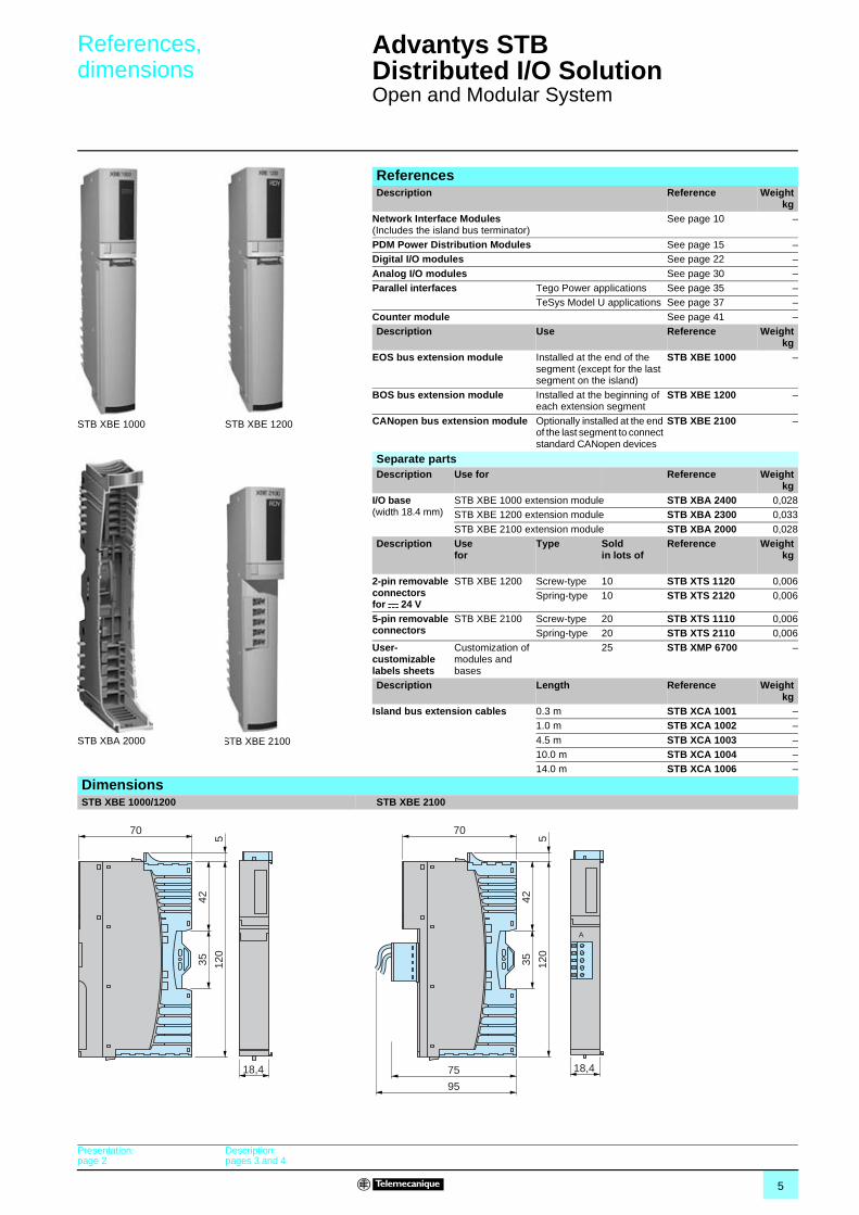
kgEOS bus extension module Installed at the end of the
segment (except for the last segment on the island)
STB XBE 1000 –
BOS bus extension module Installed at the beginning of each extension segment
STB XBE 1200 –
CANopen bus extension module Optionally installed at the end of the last segment to connect standard CANopen devices
STB XBE 2100 –STB XBE 1000 STB XBE 1200
STB XBE 2100
Separate partsDescription Use for Reference Weight
kgI/O base (width 18.4 mm)
STB XBE 1000 extension module STB XBA 2400 0,028STB XBE 1200 extension module STB XBA 2300 0,033
STB XBE 2100 extension module STB XBA 2000 0,028Description Use
forType Sold
in lots ofReference Weight
kg
2-pin removable connectors for c 24 V
STB XBE 1200 Screw-type 10 STB XTS 1120 0,006Spring-type 10 STB XTS 2120 0,006
5-pin removable connectors
STB XBE 2100 Screw-type 20 STB XTS 1110 0,006Spring-type 20 STB XTS 2110 0,006
User-customizable labels sheets
Customization of modules and bases
25 STB XMP 6700 –
Description Length Reference Weightkg
Island bus extension cables 0.3 m STB XCA 1001 –1.0 m STB XCA 1002 –
4.5 m STB XCA 1003 –10.0 m STB XCA 1004 –14.0 m STB XCA 1006 –
STB XBA 2000
DimensionsSTB XBE 1000/1200 STB XBE 2100
70
4235 12
05
18,4
70
75
95
4235 12
05
A
18,4
Presentation:page 2
Description:pages 3 and 4
6
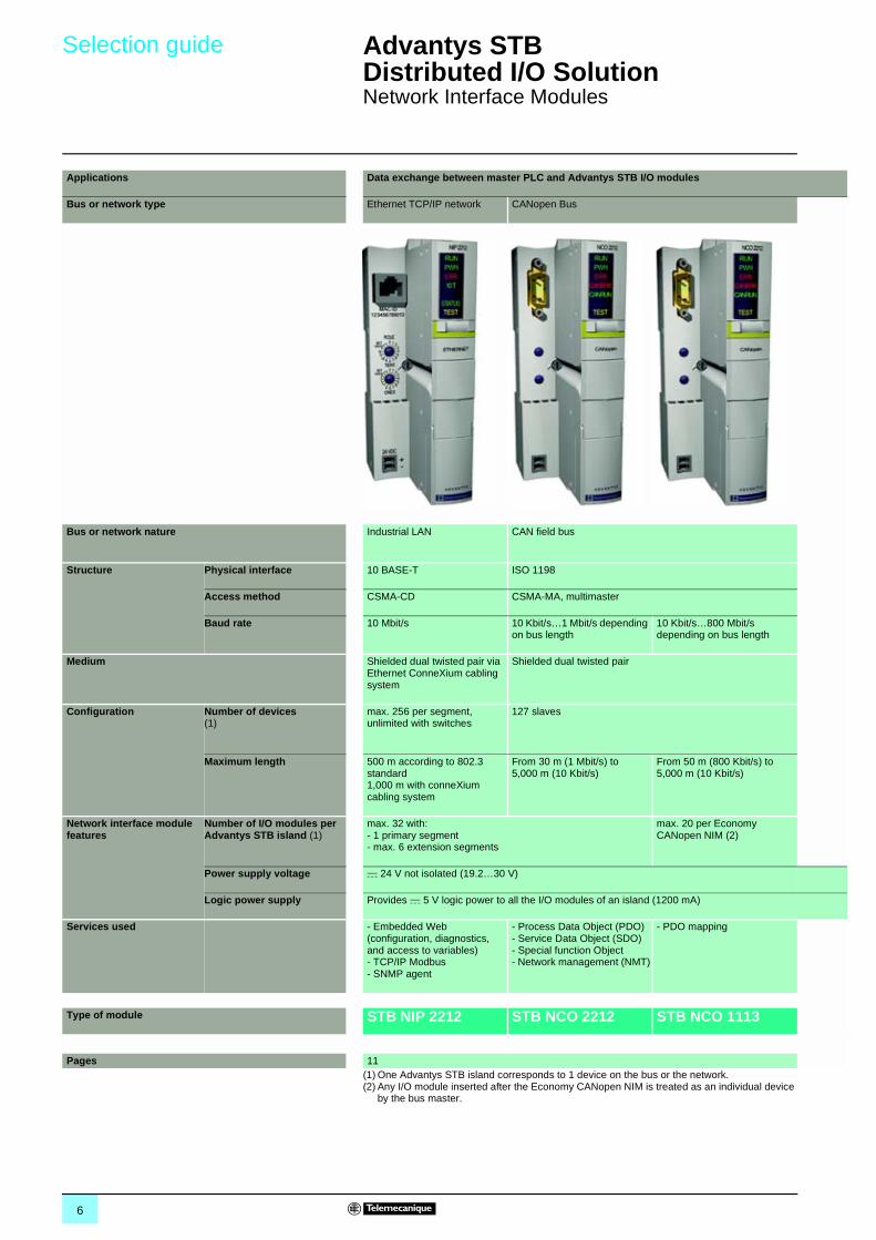
Selection guide Advantys STB Distributed I/O Solution 1
Network Interface Modules
(1) One Advantys STB island corresponds to 1 device on the bus or the network.(2) Any I/O module inserted after the Economy CANopen NIM is treated as an individual device
by the bus master.
Applications Data exchange between master PLC and Advantys STB I/O modules
Bus or network type Ethernet TCP/IP network CANopen Bus
Bus or network nature Industrial LAN CAN field bus
Structure Physical interface 10 BASE-T ISO 1198
Access method CSMA-CD CSMA-MA, multimaster
Baud rate 10 Mbit/s 10 Kbit/s…1 Mbit/s depending on bus length
10 Kbit/s…800 Mbit/s depending on bus length
Medium Shielded dual twisted pair via Ethernet ConneXium cabling system
Shielded dual twisted pair
Configuration Number of devices(1)
max. 256 per segment, unlimited with switches
127 slaves
Maximum length 500 m according to 802.3 standard1,000 m with conneXium cabling system
From 30 m (1 Mbit/s) to 5,000 m (10 Kbit/s)
From 50 m (800 Kbit/s) to 5,000 m (10 Kbit/s)
Network interface module features
Number of I/O modules per Advantys STB island (1)
max. 32 with: - 1 primary segment - max. 6 extension segments
max. 20 per Economy CANopen NIM (2)
Power supply voltage c 24 V not isolated (19.2…30 V)
Logic power supply Provides c 5 V logic power to all the I/O modules of an island (1200 mA)
Services used - Embedded Web (configuration, diagnostics, and access to variables)- TCP/IP Modbus- SNMP agent
- Process Data Object (PDO)- Service Data Object (SDO)- Special function Object- Network management (NMT)
- PDO mapping
Type of module STB NIP 2212 STB NCO 2212 STB NCO 1113
Pages 11
7
1
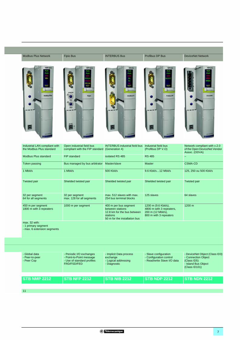
Modbus Plus Network Fipio Bus INTERBUS Bus Profibus DP Bus DeviceNet Network
Industrial LAN compliant with the Modbus Plus standard
Open industrial field bus compliant with the FIP standard
INTERBUS industrial field bus (Generation 4)
Industrial field bus (Profibus DP V.O)
Network compliant with v.2.0 of the Open DeviceNet Vendor Assoc. (ODVA)
Modbus Plus standard FIP standard isolated RS 485 RS 485 –
Token passing Bus managed by bus arbitrator Master/slave Master CSMA-CD
1 Mbit/s 1 Mbit/s 500 Kbit/s 9.6 Kbit/s…12 Mbit/s 125, 250 ou 500 Kbit/s
Twisted pair Shielded twisted pair Shielded twisted pair Shielded twisted pair Twisted pair
32 per segment64 for all segments
32 per segmentmax. 128 for all segments
max. 512 slaves with max. 254 bus terminal blocks
125 slaves 64 slaves
450 m per segment1800 m with 3 repeaters
1000 m per segment 400 m per bus segment between stations12.8 km for the bus between stations50 m for the installation bus
1200 m (9.6 Kbit/s), 4800 m with 3 repeaters,200 m (12 Mbit/s), 800 m with 3 repeaters
1200 m
max. 32 with: - 1 primary segment - max. 6 extension segments
- Global data- Peer-to-peer - Peer Cop
- Periodic I/O exchanges- Point-to-Point message- Use of standard profiles FRD/FSD/FED
- Implicit Data process exchange- Logical addressing- Diagnostic
- Slave configuration- Configuration control- Read/write Slave I/O data
- DeviceNet Object (Class ID3)- Connection Object (Class ID5)- Island Bus Object (Class ID101)
STB NMP 2212 STB NFP 2212 STB NIB 2212 STB NDP 2212 STB NDN 2212
11
8
Presentation Advantys STB Distributed I/O Solution 1
Network Interface Modules
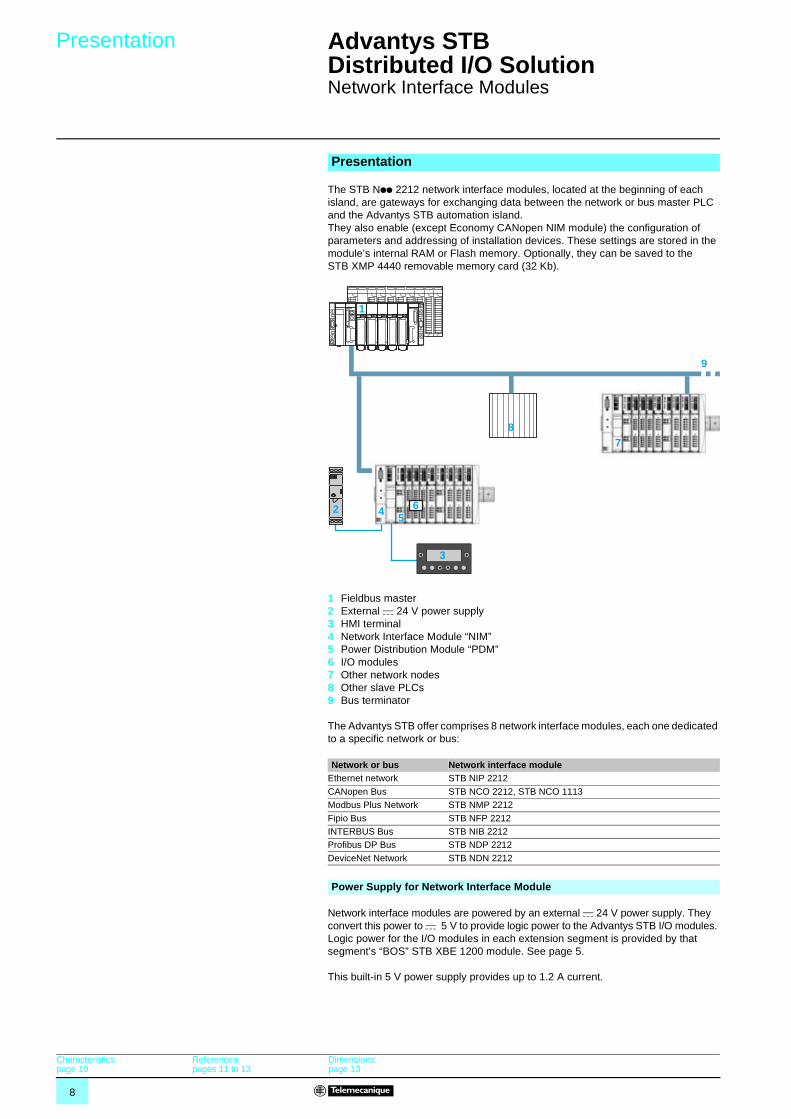
The STB Npp 2212 network interface modules, located at the beginning of each island, are gateways for exchanging data between the network or bus master PLC and the Advantys STB automation island. They also enable (except Economy CANopen NIM module) the configuration of parameters and addressing of installation devices. These settings are stored in the module’s internal RAM or Flash memory. Optionally, they can be saved to the STB XMP 4440 removable memory card (32 Kb).
1 Fieldbus master2 External c 24 V power supply3 HMI terminal4 Network Interface Module “NIM”5 Power Distribution Module “PDM”6 I/O modules7 Other network nodes8 Other slave PLCs9 Bus terminator
The Advantys STB offer comprises 8 network interface modules, each one dedicated to a specific network or bus:
Network interface modules are powered by an external c 24 V power supply. They convert this power to c 5 V to provide logic power to the Advantys STB I/O modules. Logic power for the I/O modules in each extension segment is provided by that segment’s “BOS” STB XBE 1200 module. See page 5.
This built-in 5 V power supply provides up to 1.2 A current.
Presentation
Network or bus Network interface moduleEthernet network STB NIP 2212
CANopen Bus STB NCO 2212, STB NCO 1113Modbus Plus Network STB NMP 2212
Fipio Bus STB NFP 2212INTERBUS Bus STB NIB 2212Profibus DP Bus STB NDP 2212
DeviceNet Network STB NDN 2212
3
1
87
9
2 45
6
Power Supply for Network Interface Module
Characteristics:page 10
References:pages 11 to 13
Dimensions:page 13
9
Description Advantys STB Distributed I/O Solution 1
Network Interface Modules
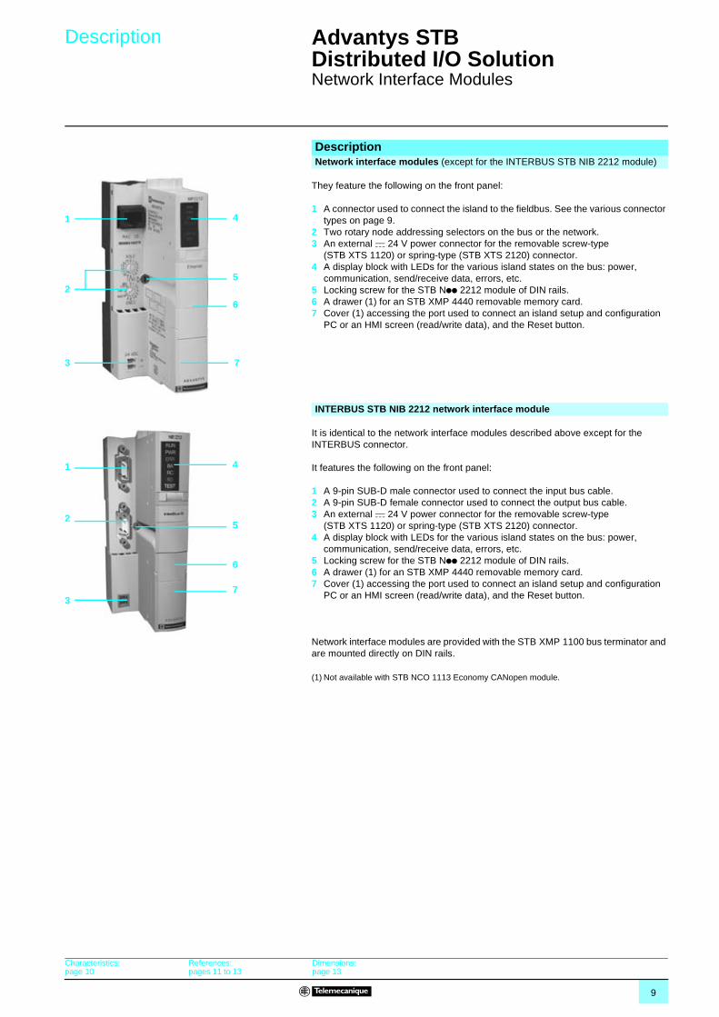
They feature the following on the front panel:
1 A connector used to connect the island to the fieldbus. See the various connector types on page 9.
2 Two rotary node addressing selectors on the bus or the network.3 An external c 24 V power connector for the removable screw-type
(STB XTS 1120) or spring-type (STB XTS 2120) connector.4 A display block with LEDs for the various island states on the bus: power,
communication, send/receive data, errors, etc.5 Locking screw for the STB Npp 2212 module of DIN rails. 6 A drawer (1) for an STB XMP 4440 removable memory card.7 Cover (1) accessing the port used to connect an island setup and configuration
PC or an HMI screen (read/write data), and the Reset button.
It is identical to the network interface modules described above except for the INTERBUS connector.
It features the following on the front panel:
1 A 9-pin SUB-D male connector used to connect the input bus cable.2 A 9-pin SUB-D female connector used to connect the output bus cable.3 An external c 24 V power connector for the removable screw-type
(STB XTS 1120) or spring-type (STB XTS 2120) connector.4 A display block with LEDs for the various island states on the bus: power,
communication, send/receive data, errors, etc.5 Locking screw for the STB Npp 2212 module of DIN rails. 6 A drawer (1) for an STB XMP 4440 removable memory card.7 Cover (1) accessing the port used to connect an island setup and configuration
PC or an HMI screen (read/write data), and the Reset button.
Network interface modules are provided with the STB XMP 1100 bus terminator and are mounted directly on DIN rails.
(1) Not available with STB NCO 1113 Economy CANopen module.
DescriptionNetwork interface modules (except for the INTERBUS STB NIB 2212 module)
1
2
3
4
5
6
7
INTERBUS STB NIB 2212 network interface module
1
2
3
4
5
6
7
Characteristics:page 10
References:pages 11 to 13
Dimensions:page 13
10
Characteristics Advantys STB Distributed I/O Solution 1
Network Interface Modules
The Economy CANopen NIM (STB NCO 1113) allows the bus master to view any I/O module following the STB NCO 1113 as an individual device. Its configuration and setup are performed by exporting the EDS file to the island master configuration software.
The I/O modules that depend on the STB NCO 1113 module are integrated in the PL7/Unity network configuration software and directly exchange data over the fieldbus. As a result, the custom configuration of the I/O modules (using the Advantys configuration software) and the use of reflex functions are not available with the Economy CANopen Interface network module.
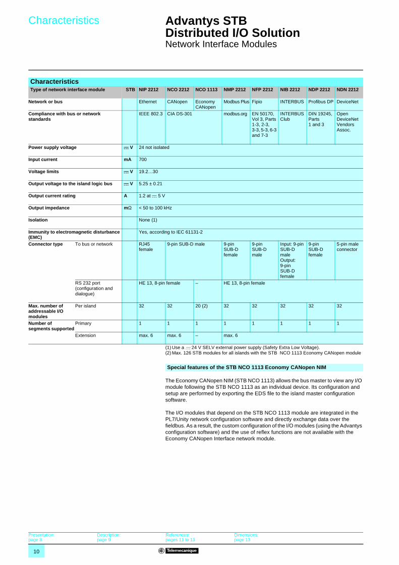
CharacteristicsType of network interface module STB NIP 2212 NCO 2212 NCO 1113 NMP 2212 NFP 2212 NIB 2212 NDP 2212 NDN 2212
Network or bus Ethernet CANopen Economy CANopen
Modbus Plus Fipio INTERBUS Profibus DP DeviceNet
Compliance with bus or network standards
IEEE 802.3 CIA DS-301 modbus.org EN 50170, Vol 3, Parts 1-3, 2-3, 3-3, 5-3, 6-3 and 7-3
INTERBUS Club
DIN 19245, Parts 1 and 3
Open DeviceNet Vendors Assoc.
Power supply voltage c V 24 not isolated
Input current mA 700
Voltage limits c V 19.2…30
Output voltage to the island logic bus c V 5.25 ± 0.21
Output current rating A 1.2 at c 5 V
Output impedance mΩ < 50 to 100 kHz
Isolation None (1)
Immunity to electromagnetic disturbance (EMC)
Yes, according to IEC 61131-2
Connector type To bus or network RJ45 female
9-pin SUB-D male 9-pin SUB-D female
9-pin SUB-D male
Input: 9-pin SUB-D maleOutput: 9-pin SUB-D female
9-pin SUB-D female
5-pin male connector
RS 232 port (configuration and dialogue)
HE 13, 8-pin female – HE 13, 8-pin female
Max. number of addressable I/O modules
Per island 32 32 20 (2) 32 32 32 32 32
Number of segments supported
Primary 1 1 1 1 1 1 1 1
Extension max. 6 max. 6 – max. 6
(1) Use a c 24 V SELV external power supply (Safety Extra Low Voltage). (2) Max. 126 STB modules for all islands with the STB NCO 1113 Economy CANopen module
Special features of the STB NCO 1113 Economy CANopen NIM
Presentation:page 8
Description:page 9
References:pages 11 to 13
Dimensions:page 13
11
References Advantys STB Distributed I/O Solution 1
Network Interface Modules
(1) Except with STB NCO 1113 Economy CANopen NIM module.
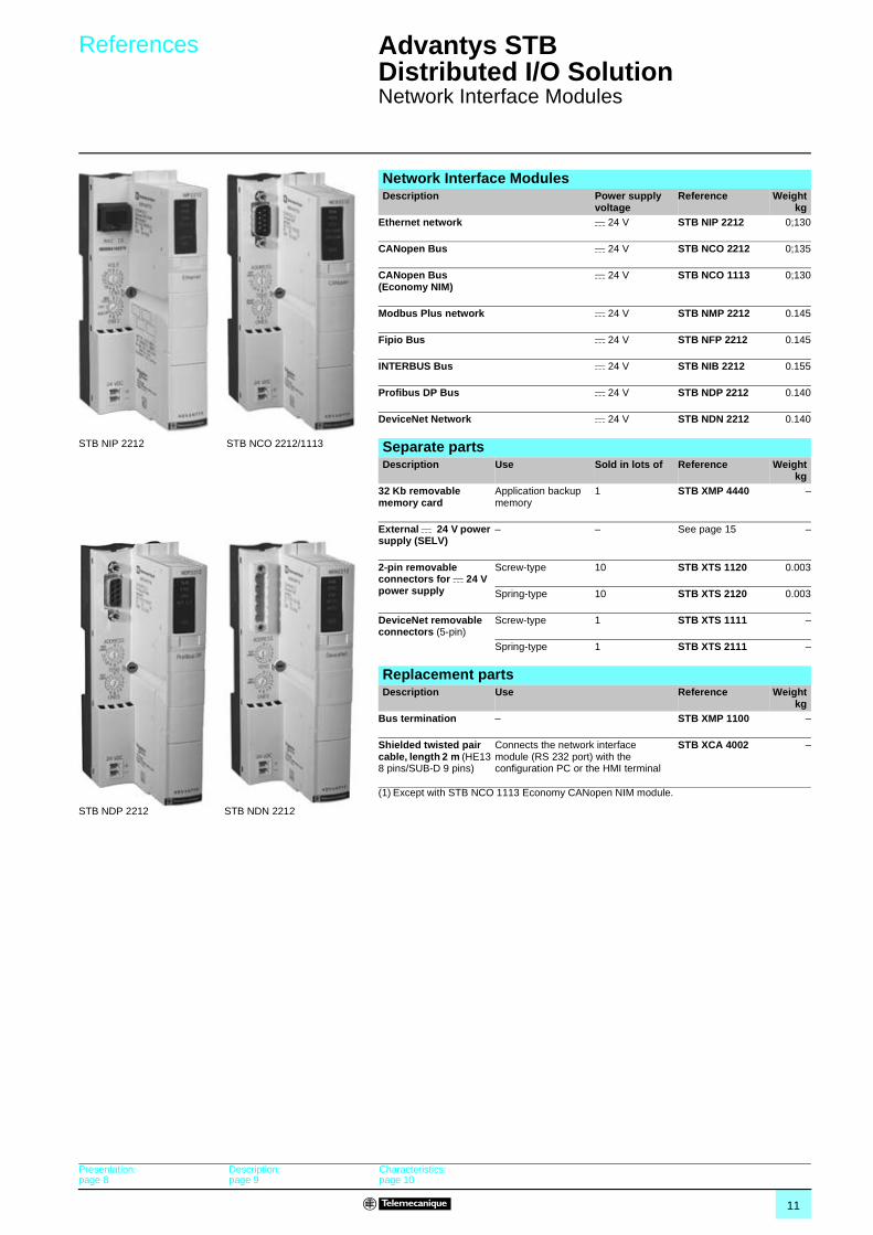
Network Interface ModulesDescription Power supply
voltageReference Weight
kgEthernet network c 24 V STB NIP 2212 0;130
CANopen Bus c 24 V STB NCO 2212 0;135
CANopen Bus(Economy NIM)
c 24 V STB NCO 1113 0;130
Modbus Plus network c 24 V STB NMP 2212 0.145
Fipio Bus c 24 V STB NFP 2212 0.145
INTERBUS Bus c 24 V STB NIB 2212 0.155
Profibus DP Bus c 24 V STB NDP 2212 0.140
DeviceNet Network c 24 V STB NDN 2212 0.140
STB NIP 2212 STB NCO 2212/1113
STB NDP 2212 STB NDN 2212
Separate partsDescription Use Sold in lots of Reference Weight
kg32 Kb removable memory card
Application backup memory
1 STB XMP 4440 –
External c 24 V power supply (SELV)
– – See page 15 –
2-pin removable connectors for c 24 V power supply
Screw-type 10 STB XTS 1120 0.003
Spring-type 10 STB XTS 2120 0.003
DeviceNet removable connectors (5-pin)
Screw-type 1 STB XTS 1111 –
Spring-type 1 STB XTS 2111 –
Replacement partsDescription Use Reference Weight
kgBus termination – STB XMP 1100 –
Shielded twisted pair cable, length 2 m (HE13 8 pins/SUB-D 9 pins)
Connects the network interface module (RS 232 port) with the configuration PC or the HMI terminal
STB XCA 4002 –
Presentation:page 8
Description: page 9
Characteristics:page 10
12
References (continued) Advantys STB Distributed I/O Solution 1
Network Interface Modules
(1) Cable compliant with EIA/TIA-568 standard and IEC 1180/EN 50 173 in class D. For UL and CSA 22.1 certified cables, add letter U to end of the reference.
Connection accessories Ethernet Network Description Fitted at both ends Length Reference Weight
kgStraight shielded twisted pair cable for connecting hubs and switches
2 RJ45 connectors to connect data terminal equipment (DTE)
2 m 490 NTW 000 02(1)
–
5 m 490 NTW 000 05 (1)
–
12 m 490 NTW 00012 (1)
–
40 m 490 NTW 000 40 (1)
–
80 m 490 NTW 000 80 (1)
–
490 NTW 000 pp
CANopen BusDescription Use Reference Weight
kgJunction box For T connection (15-pin SUB-D connector)
to 1 or 2 CANopen bus(es) (9-pin SUB-D female connectors)
TSX CPP ACC 1 –
Modbus Plus NetworkDescription Use Reference Weight
kg9 pin SUB-D male connector
Connection of the Modbus Plus connector
AS MBKT 085 –
Modbus Plus junction box
IP 20 device for T connections 990 NAD 230 00 0.230
IP 65 unit for T connections, supports 1 RJ45 connector on front panel
990 NAD 230 10 0.650
IP 20 T connector with 2 RJ45 connectors for Modbus Plus cable and one 9 pin SUB-D connector for auxiliary devices
170 XTS 020 00 0.260
Description Use Length Reference WeightkgFrom To
Modbus Plus drop cables
IP 20 170 XTS 020 00 T connector
IP 20 170 XTS 020 00 T connector
0.25 m 170 MCI 020 10 –
1 m 170 MCI 020 36 –3 m 170 MCI 021 20 –10 m 170 MCI 020 80 –
STB NMP 2212 network interface module
990 NAD 230 00 Junction box
2.4 m 990 NAD 211 10 0.530
6 m 990 NAD 211 30 0.530
Fipio BusDescription Use Characteristics Reference Weight
kgFemale connectors (9 pin SUB-D)
On STB NFP 2212 network interface module
Black polycarbonate IP 20
TSX FP ACC 12 0.040
Zamak TSX FP ACC 2 0.080
Bus connection unit Junction for main cable
Black polycarbonate IP 20
TSX FP ACC 14 0.120
Zamak IP 65 TSX FP ACC 4 0.660
Drop cables 8 mm, 2 shielded twisted pairs 150 Ω For standard environments
100 m TSX FP CC 100 5.680200 m TSX FP CC 200 10.920
500 m TSX FP CC 500 30.000
TSX FP ACC 12
TSX FP ACC 14 TSX FP ACC 4
Presentation:page 8
Description: page 9
Characteristics:page 10
Dimensions:page 13
13
References (continued),
dimensionsAdvantys STB Distributed I/O Solution 1
Network Interface Modules
Connection accessories (continued)
INTERBUS BusDescription Use Length Reference Weight
kgInstallation bus cables
Prefitted cables to connect 2 network interface modules “NIM”
0.110 m 170 MCI 007 00 –
1 m 170 MCI 100 00 –
Junction interface To connect inter-station bus to installation bus
– 170 BNO 671 00 –
Inter-station bus cables
– 100 m TSX IBS CA 100 –
400 m TSX IBS CA 400 –
Profibus DP BusDescription Use Length Reference Weight
kgConnectors for STB NDP 2212 network interface module
Bus terminator – 490 NAD 911 03 –
Intermediate connection
– 490 NAD 911 04 –
Intermediate connection with terminal port
– 490 NAD 911 05 –
Profibus DP connection cables
– 100 m TSX PBS CA 100 –
400 m TSX PBS CA 400 –
DeviceNet NetworkDescription Use Type Reference Weight
kgFemale 5-pin connectors
For STB NDN 2212 network interface module
Screw-type STB XTS 1111 –
Spring-type STB XTS 2111 –
DimensionsSTB Npp 2212/NCO 1113
2020
4235
128,
3
70
Presentation:page 8
Description: page 9
Characteristics: page 10
14
Presentation,description,characteristics
Advantys STB Distributed I/O Solution 1
Power Distribution Modules
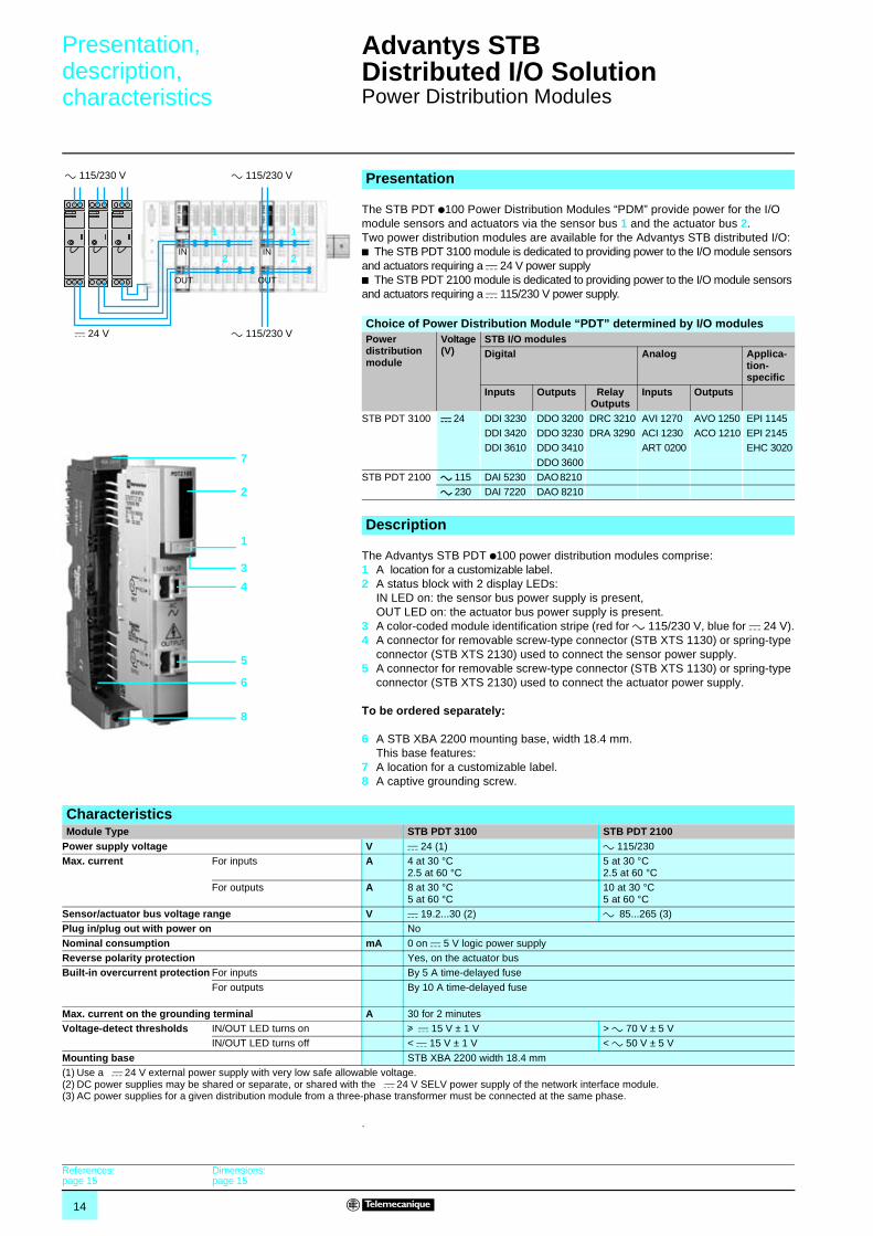
The STB PDT p100 Power Distribution Modules “PDM” provide power for the I/O module sensors and actuators via the sensor bus 1 and the actuator bus 2.Two power distribution modules are available for the Advantys STB distributed I/O:b The STB PDT 3100 module is dedicated to providing power to the I/O module sensors and actuators requiring a c 24 V power supplyb The STB PDT 2100 module is dedicated to providing power to the I/O module sensors and actuators requiring a c 115/230 V power supply.
The Advantys STB PDT p100 power distribution modules comprise:1 A location for a customizable label.2 A status block with 2 display LEDs:
IN LED on: the sensor bus power supply is present,OUT LED on: the actuator bus power supply is present.
3 A color-coded module identification stripe (red for a 115/230 V, blue for c 24 V).4 A connector for removable screw-type connector (STB XTS 1130) or spring-type
connector (STB XTS 2130) used to connect the sensor power supply.5 A connector for removable screw-type connector (STB XTS 1130) or spring-type
connector (STB XTS 2130) used to connect the actuator power supply.
To be ordered separately:
6 A STB XBA 2200 mounting base, width 18.4 mm.This base features:
7 A location for a customizable label.8 A captive grounding screw.
.
Presentation
Choice of Power Distribution Module “PDT” determined by I/O modulesPower distribution module
Voltage(V)
STB I/O modulesDigital Analog Applica-
tion-specific
Inputs Outputs Relay Outputs
Inputs Outputs
STB PDT 3100 c 24 DDI 3230 DDO 3200 DRC 3210 AVI 1270 AVO 1250 EPI 1145DDI 3420 DDO 3230 DRA 3290 ACI 1230 ACO 1210 EPI 2145DDI 3610 DDO 3410 ART 0200 EHC 3020
DDO 3600STB PDT 2100 a 115 DAI 5230 DAO 8210
a 230 DAI 7220 DAO 8210
c 24 V
IN
OUT
IN
OUT
a 115/230 V a 115/230 V
a 115/230 V
1 1
2 2
Description
7
2
3
4
5
6
8
1
CharacteristicsModule Type STB PDT 3100 STB PDT 2100
Power supply voltage V c 24 (1) a 115/230Max. current For inputs A 4 at 30 °C
2.5 at 60 °C5 at 30 °C2.5 at 60 °C
For outputs A 8 at 30 °C5 at 60 °C
10 at 30 °C5 at 60 °C
Sensor/actuator bus voltage range V c 19.2...30 (2) a 85...265 (3)Plug in/plug out with power on No
Nominal consumption mA 0 on c 5 V logic power supply Reverse polarity protection Yes, on the actuator busBuilt-in overcurrent protection For inputs By 5 A time-delayed fuse
For outputs By 10 A time-delayed fuse
Max. current on the grounding terminal A 30 for 2 minutesVoltage-detect thresholds IN/OUT LED turns on u c 15 V ± 1 V > a 70 V ± 5 V
IN/OUT LED turns off < c 15 V ± 1 V < a 50 V ± 5 V
Mounting base STB XBA 2200 width 18.4 mm(1) Use a c 24 V external power supply with very low safe allowable voltage.(2) DC power supplies may be shared or separate, or shared with the c 24 V SELV power supply of the network interface module.(3) AC power supplies for a given distribution module from a three-phase transformer must be connected at the same phase.
References:page 15
Dimensions:page 15
15
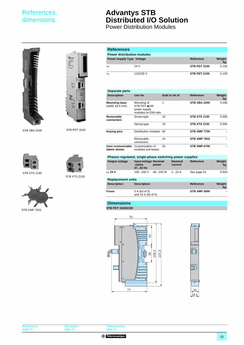
ReferencesPower distribution modulesPower Supply Type Voltage Reference Weight
kgc 24 V STB PDT 3100 0.130
a 115/230 V STB PDT 2100 0.129
STB PDT 3100
Separate partsDescription Use for Sold in lot of Reference Weight
kgMounting base (width 18.4 mm)
Mounting of STB PDT p100 power supply modules on DIN rails
1 STB XBA 2200 0.035
Removable connectors
Screw-type 10 STB XTS 1130 0.006
Spring-type 10 STB XTS 2130 0.006
Keying pins Distribution modules 60 STB XMP 7700 –
Removable connectors
24 STB XMP 7810 –
User-customizable labels sheets
Customization of modules and bases
25 STB XMP 6700 –
STB XBA 2200
STB XTS 1130STB XTS 2130
STB XMP 7810
Phaseo regulated, single-phase switching power supplies Output voltage Input voltage
mains 47...63 Hz
Nominal power
Nominal current
Reference Weightkg
c 24 V 100...240 V 48...240 W 2...10 A See page 51 0.520
Replacement unitsDescription Description Reference Weight
kgFuses 5 A (lot of 5)
and 10 A (lot of 5)STB XMP 5600 –
DimensionsSTB PDT 3100/2100
INPUT
OUTPUT+–
18,4
16
70
77
4235
128,
3
137,
3
Presentation:page 14
Description:page 14
Characteristics:page 14
References,dimensions
Advantys STB Distributed I/O Solution 1
Power Distribution Modules
16
Selection guide Advantys STB Distributed I/O Solution 1
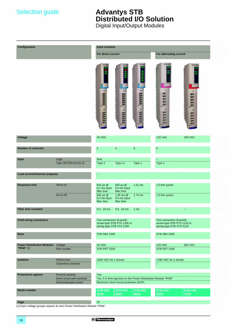
Digital Input/Output Modules
Configuration Input modules
For direct current For alternating current
Voltage 24 VDC 115 VAC 230 VAC
Number of channels 2 4 6 2
Input Logic Sink –Type (IEC/EN 61131-2) Type 2 Type 1+ Type 1 Type 1
Load current/channel (outputs) –
Response time Off-to-on 610 µs @ 0.2 ms input filter time
925 µs @ 0.5 ms input filter time
1.21 ms 1.5 line cycles
On-to-off 625 µs @ 0.2 ms input filter time
1.35 ms @ 0.5 ms input filter time
1.74 ms 1.5 line cycles
Filter time constant 0.2...16 ms 0.5...16 ms 1 ms – –
Field wiring connectors Two connectors (6-point): screw-type STB XTS 1100 orspring-type STB XTS 2100
Two connectors (5-point): screw-type STB XTS 1110 orspring-type STB XTS 2110
Base STB XBA 1000 STB XBA 2000
Power Distribution Modules “PDM” (1)
Voltage 24 VDC 115 VAC 230 VAC
Part number STB PDT 3100 STB PDT 2100
Isolation Field-to-bus 1500 VDC for 1 minute 1780 VAC for 1 minuteChannel-to-channel – –
Protections against Reverse polarity YesShort circuit and overload Yes, 5 A time-lag fuse on the Power Distribution Module “PDM”Sensor/actuator power Electronic short-circuit protection (SCP)
Model number STB DDI 3230
STB DDI 3420
STB DDI 3610
STB DAI5230
STB DAI 7220
Page 22(1) Each voltage groupe requies its own Power Distribution Module “PDM”.
17
1
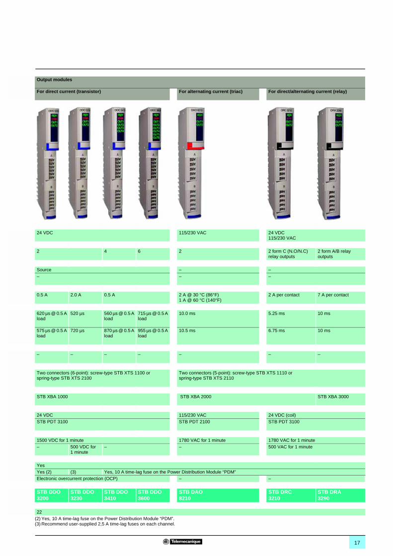
Output modules
For direct current (transistor) For alternating current (triac) For direct/alternating current (relay)
24 VDC 115/230 VAC 24 VDC115/230 VAC
2 4 6 2 2 form C (N.O/N.C) relay outputs
2 form A/B relay outputs
Source – –– – –
0.5 A 2.0 A 0.5 A 2 A @ 30 °C (86°F)1 A @ 60 °C (140°F)
2 A per contact 7 A per contact
620 µs @ 0.5 A load
520 µs 560 µs @ 0.5 A load
715 µs @ 0.5 A load
10.0 ms 5.25 ms 10 ms
575 µs @ 0.5 A load
720 µs 870 µs @ 0.5 A load
955 µs @ 0.5 A load
10.5 ms 6.75 ms 10 ms
– – – – – – –
Two connectors (6-point): screw-type STB XTS 1100 orspring-type STB XTS 2100
Two connectors (5-point): screw-type STB XTS 1110 orspring-type STB XTS 2110
STB XBA 1000 STB XBA 2000 STB XBA 3000
24 VDC 115/230 VAC 24 VDC (coil)STB PDT 3100 STB PDT 2100 STB PDT 3100
1500 VDC for 1 minute 1780 VAC for 1 minute 1780 VAC for 1 minute– 500 VDC for
1 minute– – 500 VAC for 1 minute
YesYes (2) (3) Yes, 10 A time-lag fuse on the Power Distribution Module “PDM”Electronic overcurrent protection (OCP) – –
STB DDO 3200
STB DDO 3230
STB DDO 3410
STB DDO 3600
STB DAO 8210
STB DRC 3210
STB DRA 3290
22(2) Yes, 10 A time-lag fuse on the Power Distribution Module “PDM”.(3) Recommend user-supplied 2,5 A time-lag fuses on each channel.
18
Presentation,description
Advantys STB Distributed I/O Solution 1
Digital Input/Output Modules
The STB digital input/output modules consist of input modules, output modules, and relay output modules.
The digital I/O offering is defined as follows:
b 5 digital input modules: v one 2-channel module, one 4-channel module, and one 6-channel module with 24 VDC voltage, v one 2-channel module with 115 VAC voltage, v one 2-channel module with 230 VAC voltage.
b 5 digital output modules: v two 2-channel modules, one 4-channel module, and one 6-channel module with 24 VDC voltage, v one 2-channel module with 115/230 VAC voltage.
b 2 relay output modules: v one 2 form C relay outputs, v one 2 form A/B relay outputs.
A typical digital input/output module comprises the following:
1 A location for user-customizable label.
2 A display block showing:v the state of the module (RDY, ERR),v the state of channel (INp or OUTp).
3 A color-coded module identification stripe.
4 Two receptacles for field-wiring connectors.
To be ordered separately:
b I/O bases width 13.9, 18.4 or 28.1 mm, depending on the model of I/O module STB XBA 1000/2000/3000.These bases feature a location for the user-customizable label.
b Removable screw terminal (5 or 6-channel) STB XTS 1110/1100 or removable spring terminal (5 or 6-channel) STB XTS 2110/2100.
b Mechanical keying pin to insert between:v the I/O module and this I/O base: STB XMP 7700,v the field wiring connector and this I/O module: STB XMP 7800,to ensure that the I/O module, I/O base and field wiring connector are properly matched.
b User-customizable labels sheets: STB XMP 6700.
Presentation
Description
1
2
34
Characteristics: :pages 19 to 21
References:page 22
Dimensions:page 23
Wiring:pages 23 to 25
19
Characteristics Advantys STB Distributed I/O Solution 1
Digital Input/Output Modules
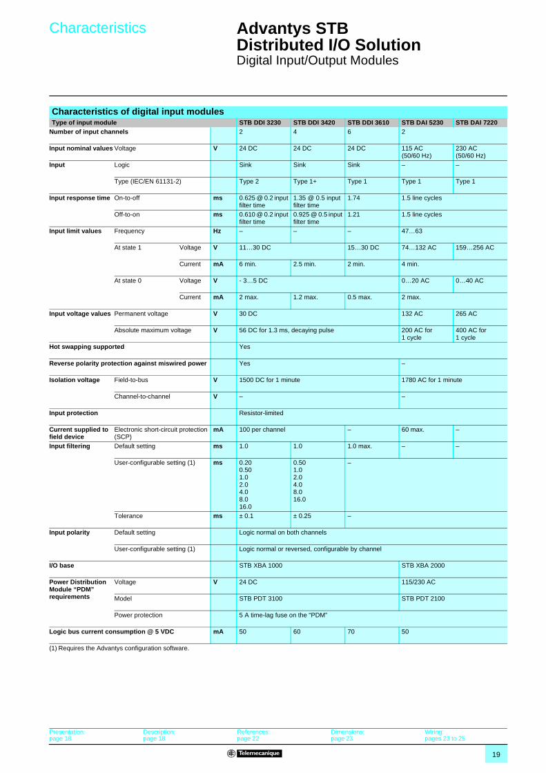
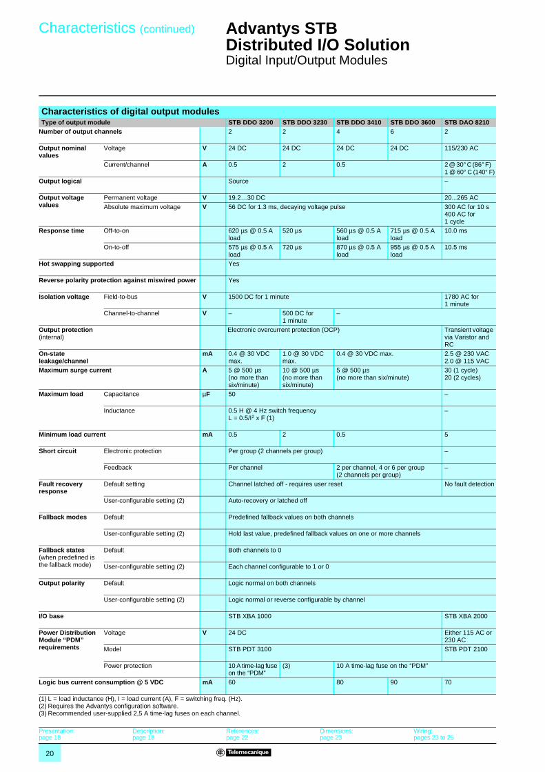
Characteristics of digital input modulesType of input module STB DDI 3230 STB DDI 3420 STB DDI 3610 STB DAI 5230 STB DAI 7220
Number of input channels 2 4 6 2
Input nominal values Voltage V 24 DC 24 DC 24 DC 115 AC (50/60 Hz)
230 AC (50/60 Hz)
Input Logic Sink Sink Sink – –
Type (IEC/EN 61131-2) Type 2 Type 1+ Type 1 Type 1 Type 1
Input response time On-to-off ms 0.625 @ 0.2 input filter time
1.35 @ 0.5 input filter time
1.74 1.5 line cycles
Off-to-on ms 0.610 @ 0.2 input filter time
0.925 @ 0.5 input filter time
1.21 1.5 line cycles
Input limit values Frequency Hz – – – 47…63
At state 1 Voltage V 11…30 DC 15…30 DC 74…132 AC 159…256 AC
Current mA 6 min. 2.5 min. 2 min. 4 min.
At state 0 Voltage V - 3…5 DC 0…20 AC 0…40 AC
Current mA 2 max. 1.2 max. 0.5 max. 2 max.
Input voltage values Permanent voltage V 30 DC 132 AC 265 AC
Absolute maximum voltage V 56 DC for 1.3 ms, decaying pulse 200 AC for 1 cycle
400 AC for 1 cycle
Hot swapping supported Yes
Reverse polarity protection against miswired power Yes –
Isolation voltage Field-to-bus V 1500 DC for 1 minute 1780 AC for 1 minute
Channel-to-channel V – –
Input protection Resistor-limited
Current supplied to field device
Electronic short-circuit protection (SCP)
mA 100 per channel – 60 max. –
Input filtering Default setting ms 1.0 1.0 1.0 max. – –
User-configurable setting (1) ms 0.200.501.02.04.08.016.0
0.501.02.04.08.016.0
–
Tolerance ms ± 0.1 ± 0.25 –
Input polarity Default setting Logic normal on both channels
User-configurable setting (1) Logic normal or reversed, configurable by channel
I/O base STB XBA 1000 STB XBA 2000
Power Distribution Module “PDM” requirements
Voltage V 24 DC 115/230 AC
Model STB PDT 3100 STB PDT 2100
Power protection 5 A time-lag fuse on the “PDM”
Logic bus current consumption @ 5 VDC mA 50 60 70 50
(1) Requires the Advantys configuration software.
Presentation:page 18
Description:page 18
References:page 22
Dimensions:page 23
Wiring:pages 23 to 25
20
Characteristics (continued) Advantys STB Distributed I/O Solution 1
Digital Input/Output Modules
Characteristics of digital output modulesType of output module STB DDO 3200 STB DDO 3230 STB DDO 3410 STB DDO 3600 STB DAO 8210
Number of output channels 2 2 4 6 2
Output nominal values
Voltage V 24 DC 24 DC 24 DC 24 DC 115/230 AC
Current/channel A 0.5 2 0.5 2 @ 30° C (86° F) 1 @ 60° C (140° F)
Output logical Source –
Output voltage values
Permanent voltage V 19.2…30 DC 20...265 AC
Absolute maximum voltage V 56 DC for 1.3 ms, decaying voltage pulse 300 AC for 10 s 400 AC for 1 cycle
Response time Off-to-on 620 µs @ 0.5 A load
520 µs 560 µs @ 0.5 A load
715 µs @ 0.5 A load
10.0 ms
On-to-off 575 µs @ 0.5 A load
720 µs 870 µs @ 0.5 A load
955 µs @ 0.5 A load
10.5 ms
Hot swapping supported Yes
Reverse polarity protection against miswired power Yes
Isolation voltage Field-to-bus V 1500 DC for 1 minute 1780 AC for 1 minute
Channel-to-channel V – 500 DC for 1 minute
–
Output protection (internal)
Electronic overcurrent protection (OCP) Transient voltage via Varistor and RC
On-state leakage/channel
mA 0.4 @ 30 VDC max.
1.0 @ 30 VDC max.
0.4 @ 30 VDC max. 2.5 @ 230 VAC2.0 @ 115 VAC
Maximum surge current A 5 @ 500 µs (no more than six/minute)
10 @ 500 µs (no more than six/minute)
5 @ 500 µs (no more than six/minute)
30 (1 cycle) 20 (2 cycles)
Maximum load Capacitance µF 50 –
Inductance 0.5 H @ 4 Hz switch frequencyL = 0.5/I2 x F (1)
–
Minimum load current mA 0.5 2 0.5 5
Short circuit Electronic protection Per group (2 channels per group) –
Feedback Per channel 2 per channel, 4 or 6 per group (2 channels per group)
–
Fault recovery response
Default setting Channel latched off - requires user reset No fault detection
User-configurable setting (2) Auto-recovery or latched off
Fallback modes Default Predefined fallback values on both channels
User-configurable setting (2) Hold last value, predefined fallback values on one or more channels
Fallback states (when predefined is the fallback mode)
Default Both channels to 0
User-configurable setting (2) Each channel configurable to 1 or 0
Output polarity Default Logic normal on both channels
User-configurable setting (2) Logic normal or reverse configurable by channel
I/O base STB XBA 1000 STB XBA 2000
Power Distribution Module “PDM” requirements
Voltage V 24 DC Either 115 AC or 230 AC
Model STB PDT 3100 STB PDT 2100
Power protection 10 A time-lag fuse on the “PDM”
(3) 10 A time-lag fuse on the “PDM”
Logic bus current consumption @ 5 VDC mA 60 80 90 70
(1) L = load inductance (H), I = load current (A), F = switching freq. (Hz).(2) Requires the Advantys configuration software.(3) Recommended user-supplied 2,5 A time-lag fuses on each channel.
Presentation:page 18
Description:page 18
References:page 22
Dimensions:page 23
Wiring:pages 23 to 25
21
Characteristics (continued) Advantys STB Distributed I/O Solution 1
Digital Input/Output Modules
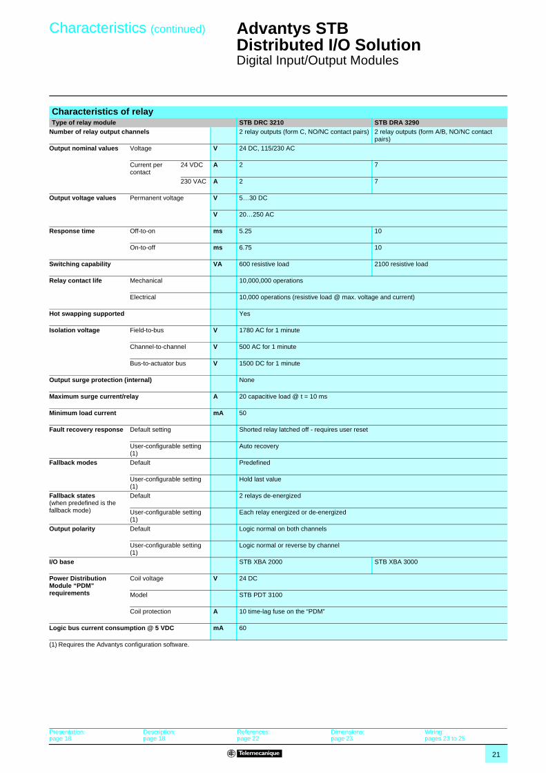
Characteristics of relay Type of relay module STB DRC 3210 STB DRA 3290
Number of relay output channels 2 relay outputs (form C, NO/NC contact pairs) 2 relay outputs (form A/B, NO/NC contact pairs)
Output nominal values Voltage V 24 DC, 115/230 AC
Current per contact
24 VDC A 2 7
230 VAC A 2 7
Output voltage values Permanent voltage V 5…30 DC
V 20…250 AC
Response time Off-to-on ms 5.25 10
On-to-off ms 6.75 10
Switching capability VA 600 resistive load 2100 resistive load
Relay contact life Mechanical 10,000,000 operations
Electrical 10,000 operations (resistive load @ max. voltage and current)
Hot swapping supported Yes
Isolation voltage Field-to-bus V 1780 AC for 1 minute
Channel-to-channel V 500 AC for 1 minute
Bus-to-actuator bus V 1500 DC for 1 minute
Output surge protection (internal) None
Maximum surge current/relay A 20 capacitive load @ t = 10 ms
Minimum load current mA 50
Fault recovery response Default setting Shorted relay latched off - requires user reset
User-configurable setting (1)
Auto recovery
Fallback modes Default Predefined
User-configurable setting (1)
Hold last value
Fallback states (when predefined is the fallback mode)
Default 2 relays de-energized
User-configurable setting (1)
Each relay energized or de-energized
Output polarity Default Logic normal on both channels
User-configurable setting (1)
Logic normal or reverse by channel
I/O base STB XBA 2000 STB XBA 3000
Power Distribution Module “PDM” requirements
Coil voltage V 24 DC
Model STB PDT 3100
Coil protection A 10 time-lag fuse on the “PDM”
Logic bus current consumption @ 5 VDC mA 60
(1) Requires the Advantys configuration software.
Presentation:page 18
Description:page 18
References:page 22
Dimensions:page 23
Wiring:pages 23 to 25
22
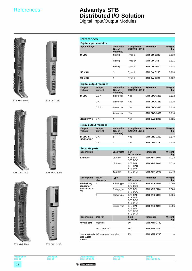
References Advantys STB Distributed I/O Solution 1
Digital Input/Output Modules
ReferencesDigital input modulesInput voltage Modularity
(No. of channels)
Compliance IEC/EN 61131-2
Reference Weightkg
24 VDC 2 (sink) Type 2 STB DDI 3230 0.110
4 (sink) Type 1+ STB DDI 342 0.111
6 (sink) Type 1 STB DDI 3610 0.112
115 VAC 2 Type 1 STB DAI 5230 0.120
230 VAC 2 Type 1 STB DAI 7220 0.122
STB DDI 3230
Digital output modulesOutput voltage
Output current
Modularity (No. of channels)
Compliance IEC/EN 61131-2
Reference Weightkg
24 VDC 0.5 A 2 (source) Yes STB DDO 3200 0.112
2 A 2 (source) Yes STB DDO 3230 0.116
0.5 A 4 (source) Yes STB DDO 3410 0.110
6 (source) Yes STB DDO 3600 0.114
115/230 VAC 2 A 2 Yes STB DAO 8210 0.125
STB DDO 3200
Relay output modulesOutput voltage
Output current
Modularity (No. of channels)
Compliance IEC/EN 61131-2
Reference Weightkg
24 VDC or 115/230 VAC
2 A 2 Yes STB DRC 3210 0.130
7 A 2 Yes STB DRA 3290 0.130
STB DRC 3210
STB XBA 1000
Separate partsDescription Base width For
I/O modulesReference Weight
kgI/O bases 13.9 mm STB DDI
STB DDO STB XBA 1000 0.024
18.4 mm STB DAI STB DAO STB DRC
STB XBA 2000 0.028
28.1 mm STB DRA STB XBA 3000 0.048
Description No. of channels
Type For I/O modules
Reference Weightkg
Field wiring connector (sold in lots of 20)
6 Screw-type STB DDI STB DDO
STB XTS 1100 0.006
Spring-type STB DDI STB DDO
STB XTS 2100 0.006
5 Screw-type STB DAI STB DAO STB DRC STB DRA
STB XTS 1110 0.006
Spring-type STB DAI STB DAO STB DRC STB DRA
STB XTS 2110 0.006
Description Use for Sold in lots of
Reference Weightkg
Keying pins Modules 60 STB XMP 7700 –
I/O connectors 96 STB XMP 7800 –
User-customizable labels sheets
I/O bases and modules 25 STB XMP 6700 –
STB XBA 1000
STB XBA 2000
Presentation:page 18
Description:page 18
Characteristics:pages 19 to 21
Dimensions:page 23
Wiring:pages 23 to 25
23
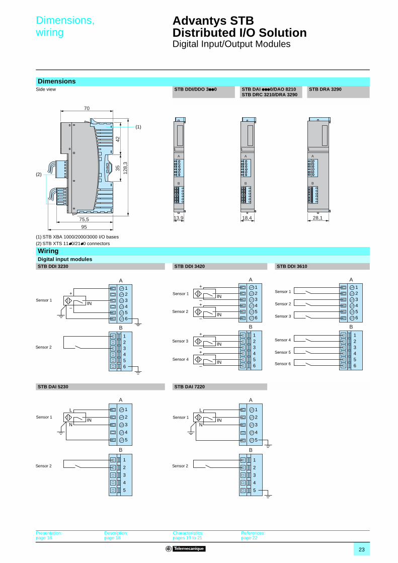
Dimensions,wiring
Advantys STB Distributed I/O Solution 1
Digital Input/Output Modules
DimensionsSide view STB DDI/DDO 3pp0 STB DAI ppp0/DAO 8210
STB DRC 3210/DRA 3290STB DRA 3290
(1) STB XBA 1000/2000/3000 I/O bases(2) STB XTS 11p0/21p0 connectors
WiringDigital input modules STB DDI 3230 STB DDI 3420 STB DDI 3610
STB DAI 5230 STB DAI 7220
70
75,5
95
4235
128,
3(1)
(2)
A
B
13,9
A
B
18,4 28,1
A
B
A
B
+
IN–
123456
123456
Sensor 1
Sensor 2
A
B
123456
123456
+
IN–+
IN–
+
IN–+
IN–
Sensor 1
Sensor 2
Sensor 3
Sensor 4
A
B
123456
123456
Sensor 1
Sensor 2
Sensor 3
Sensor 4
Sensor 5
Sensor 6
A
B
1
2
3
4
5
1
2
3
4
5
L
INN
Sensor 1
Sensor 2
A
B
1
2
3
4
5
1
2
3
4
5
L
INN
Sensor 1
Sensor 2
Presentation:page 18
Description:page 18
Characteristics:pages 19 to 21
References:page 22
24
Wiring (continued) Advantys STB Distributed I/O Solution 1
Digital Input/Output Modules
Wiring (continued)
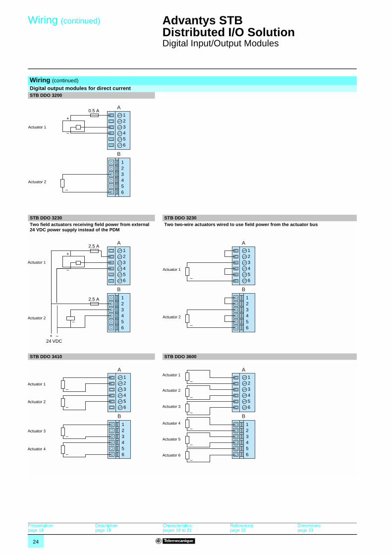
Digital output modules for direct currentSTB DDO 3200
STB DDO 3230 STB DDO 3230Two field actuators receiving field power from external 24 VDC power supply instead of the PDM
Two two-wire actuators wired to use field power from the actuator bus
STB DDO 3410 STB DDO 3600
A
B
123456
123456–
+
–
0.5 A
Actuator 1
Actuator 2
A
B
123456
123456
–
+
–
2.5 A
2.5 A
+ –24 VDC
Actuator 1
Actuator 2
A
B
123456
123456
–
–
Actuator 1
Actuator 2
A
B
123456
123456
–
–
–
–
Actuator 1
Actuator 2
Actuator 3
Actuator 4
A
B
123456
123456
–
–
–
–
–
–
Actuator 1
Actuator 2
Actuator 3
Actuator 4
Actuator 5
Actuator 6
Presentation:page 18
Description:page 18
Characteristics:pages 19 to 21
References:page 22
Dimensions:page 23
25
Wiring (continued) Advantys STB Distributed I/O Solution 1
Digital Input/Output Modules
Wiring (continued)
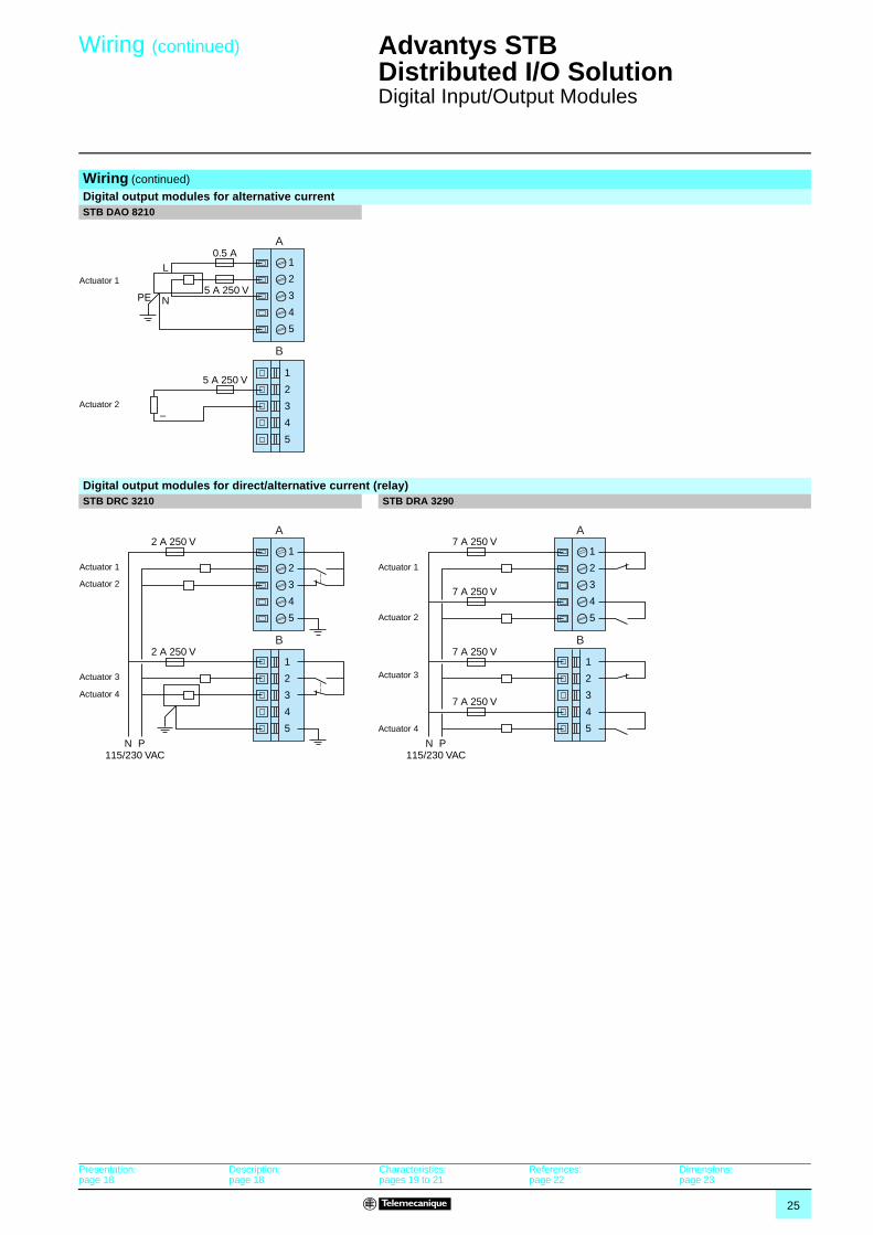
Digital output modules for alternative currentSTB DAO 8210
Digital output modules for direct/alternative current (relay)STB DRC 3210 STB DRA 3290
A
B
1
2
3
4
5
1
2
3
4
5
5 A 250 V
–
L
NPE
0.5 A
5 A 250 VActuator 1
Actuator 2
A
B
1
2
3
4
5
1
2
3
4
5
2 A 250 V
2 A 250 V
N P115/230 VAC
Actuator 1
Actuator 2
Actuator 3
Actuator 4
A
B
1
2
3
4
5
1
2
3
4
5
7 A 250 V
7 A 250 V
7 A 250 V
N P115/230 VAC
7 A 250 V
Actuator 1
Actuator 2
Actuator 3
Actuator 4
Presentation:page 18
Description:page 18
Characteristics:pages 19 to 21
References:page 22
Dimensions:page 23
26
Selection guide Advantys STB Distributed I/O Solution 1
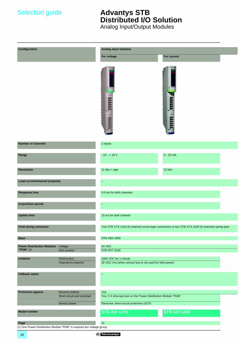
Analog Input/Output Modules
Configuration Analog input modules
For voltage For current
Number of channels 2 inputs
Range - 10…+ 10 V 0…20 mA
Resolution 11 bits + sign 12 bits
Load current/channel (outputs) –
Response time 5.0 ms for both channels
Acquisition period –
Update time 10 ms for both channel
Field wiring connector Two STB XTS 1100 (6-channel) screw-type connectors or two STB XTS 2100 (6-channel) spring-type
Base STB XBA 1000
Power Distribution Modules “PDM” (1)
Voltage 24 VDCPart number STB PDT 3100
Isolation Field-to-bus 1500 VDC for 1 minuteChannel-to-channel 30 VDC rms (when sensor bus is not used for field power)
Fallback states –
Protection against Reverse polarity YesShort circuit and overload Yes, 5 A time-lag fuse on the Power Distribution Module “PDM”
Sensor power Electronic short-circuit protection (SCP)
Model number STB AVI 1270 STB ACI 1230
Page 31(1) One Power Distribution Module “PDM” is required per voltage group.
27
1
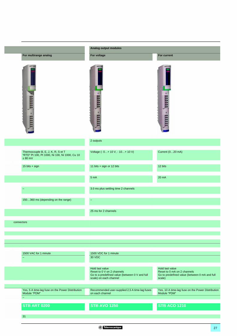
Analog output modules
For multirange analog For voltage For current
2 outputs
Thermocouple B, E, J, K, R, S et T “RTD” Pt 100, Pt 1000, Ni 100, Ni 1000, Cu 10 ± 80 mV
Voltage (- 0…+ 10 V, - 10…+ 10 V) Current (0…20 mA)
15 bits + sign 11 bits + sign or 12 bits 12 bits
5 mA 20 mA
– 3.0 ms plus settling time 2 channels
150…360 ms (depending on the range) –
25 ms for 2 channels
connectors
1500 VAC for 1 minute 1500 VDC for 1 minute– 30 VDC
Hold last valueReset to 0 V on 2 channelsGo to a predefined value (between 0 V and full scale) on each channel
Hold last valueReset to 0 mA on 2 channels Go to predefined value (between 0 mA and full scale)
Yes, 5 A time-lag fuse on the Power Distribution Module “PDM”
Recommended user-supplied 2,5 A time-lag fuses on each channel
Yes, 10 A time-lag fuse on the Power Distribution Module “PDM”
–
STB ART 0200 STB AVO 1250 STB ACO 1210
31
28
Presentation,description
Advantys STB Distributed I/O Solution 1
Analog Input/Output Modules
The STB analog inputs allow the acquisition of various analog values encountered in industrial applications.The STB analog outputs are used to control analog field devices such as variable speed drives, proportional control values, etc.
The analog I/O offering is defined as follows:
b 3 analog input modules: v one with 2 ± 10 V, single-ended analog input channels, v one with 2 0…20 mA, single-ended analog input channels,v one with 2 thermocouple, “RTD” or mV channels.
b 2 analog output modules: v one with 2 single-ended analog output channels configurable for 0…10 V or ± 10 V, v one with 2 single-ended analog current output channels at 0…20 mA.
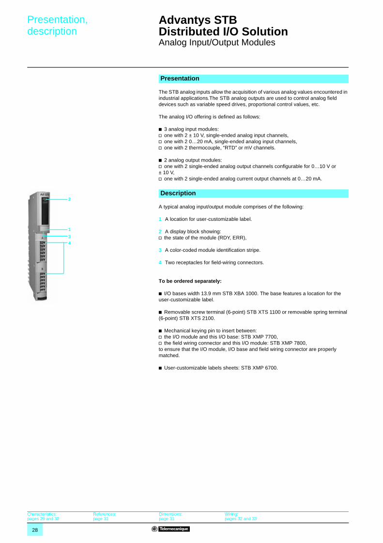
A typical analog input/output module comprises of the following:
1 A location for user-customizable label.
2 A display block showing:v the state of the module (RDY, ERR),
3 A color-coded module identification stripe.
4 Two receptacles for field-wiring connectors.
To be ordered separately:
b I/O bases width 13.9 mm STB XBA 1000. The base features a location for the user-customizable label.
b Removable screw terminal (6-point) STB XTS 1100 or removable spring terminal (6-point) STB XTS 2100.
b Mechanical keying pin to insert between:v the I/O module and this I/O base: STB XMP 7700,v the field wiring connector and this I/O module: STB XMP 7800, to ensure that the I/O module, I/O base and field wiring connector are properly matched.
b User-customizable labels sheets: STB XMP 6700.
Presentation
Description
1
2
34
Characteristics:pages 29 and 30
References:page 31
Dimensions:page 31
Wiring:pages 32 and 33
29
Characteristics Advantys STB Distributed I/O Solution 1
Analog Input/Output Modules
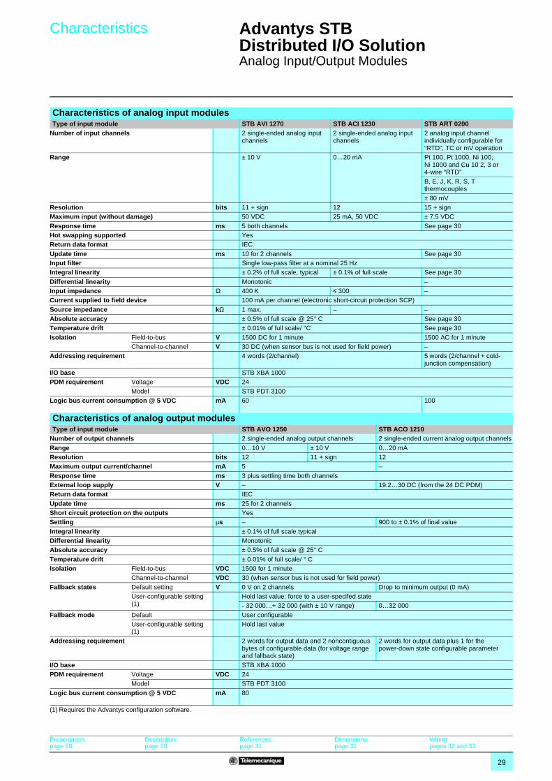
Characteristics of analog input modulesType of input module STB AVI 1270 STB ACI 1230 STB ART 0200
Number of input channels 2 single-ended analog input channels
2 single-ended analog input channels
2 analog input channel individually configurable for “RTD”, TC or mV operation
Range ± 10 V 0…20 mA Pt 100, Pt 1000, Ni 100, Ni 1000 and Cu 10 2, 3 or 4-wire “RTD”
B, E, J, K, R, S, T thermocouples
± 80 mVResolution bits 11 + sign 12 15 + signMaximum input (without damage) 50 VDC 25 mA, 50 VDC ± 7.5 VDC
Response time ms 5 both channels See page 30Hot swapping supported YesReturn data format IEC
Update time ms 10 for 2 channels See page 30Input filter Single low-pass filter at a nominal 25 HzIntegral linearity ± 0.2% of full scale, typical ± 0.1% of full scale See page 30
Differential linearity Monotonic –Input impedance Ω 400 K y 300 –Current supplied to field device 100 mA per channel (electronic short-circuit protection SCP)
Source impedance kΩ 1 max. – –Absolute accuracy ± 0.5% of full scale @ 25° C See page 30Temperature drift ± 0.01% of full scale/ °C See page 30
Isolation Field-to-bus V 1500 DC for 1 minute 1500 AC for 1 minuteChannel-to-channel V 30 DC (when sensor bus is not used for field power) –
Addressing requirement 4 words (2/channel) 5 words (2/channel + cold- junction compensation)
I/O base STB XBA 1000PDM requirement Voltage VDC 24
Model STB PDT 3100
Logic bus current consumption @ 5 VDC mA 60 100
Characteristics of analog output modulesType of input module STB AVO 1250 STB ACO 1210
Number of output channels 2 single-ended analog output channels 2 single-ended current analog output channels
Range 0…10 V ± 10 V 0…20 mAResolution bits 12 11 + sign 12Maximum output current/channel mA 5 –
Response time ms 3 plus settling time both channelsExternal loop supply V – 19.2…30 DC (from the 24 DC PDM)Return data format IEC
Update time ms 25 for 2 channelsShort circuit protection on the outputs YesSettling µs – 900 to ± 0.1% of final value
Integral linearity ± 0.1% of full scale typicalDifferential linearity MonotonicAbsolute accuracy ± 0.5% of full scale @ 25° C
Temperature drift ± 0.01% of full scale/ ° CIsolation Field-to-bus VDC 1500 for 1 minute
Channel-to-channel VDC 30 (when sensor bus is not used for field power)
Fallback states Default setting V 0 V on 2 channels Drop to minimum output (0 mA)User-configurable setting (1)
Hold last value; force to a user-specifed state- 32 000…+ 32 000 (with ± 10 V range) 0…32 000
Fallback mode Default User configurableUser-configurable setting (1)
Hold last value
Addressing requirement 2 words for output data and 2 noncontiguous bytes of configurable data (for voltage range and fallback state)
2 words for output data plus 1 for the power-down state configurable parameter
I/O base STB XBA 1000PDM requirement Voltage VDC 24
Model STB PDT 3100
Logic bus current consumption @ 5 VDC mA 80
(1) Requires the Advantys configuration software.
Presentation:page 28
Description:page 28
References:page 31
Dimensions:page 31
Wiring:pages 32 and 33
30
Characteristics (continued) Advantys STB Distributed I/O Solution 1
Analog Input/Output Modules
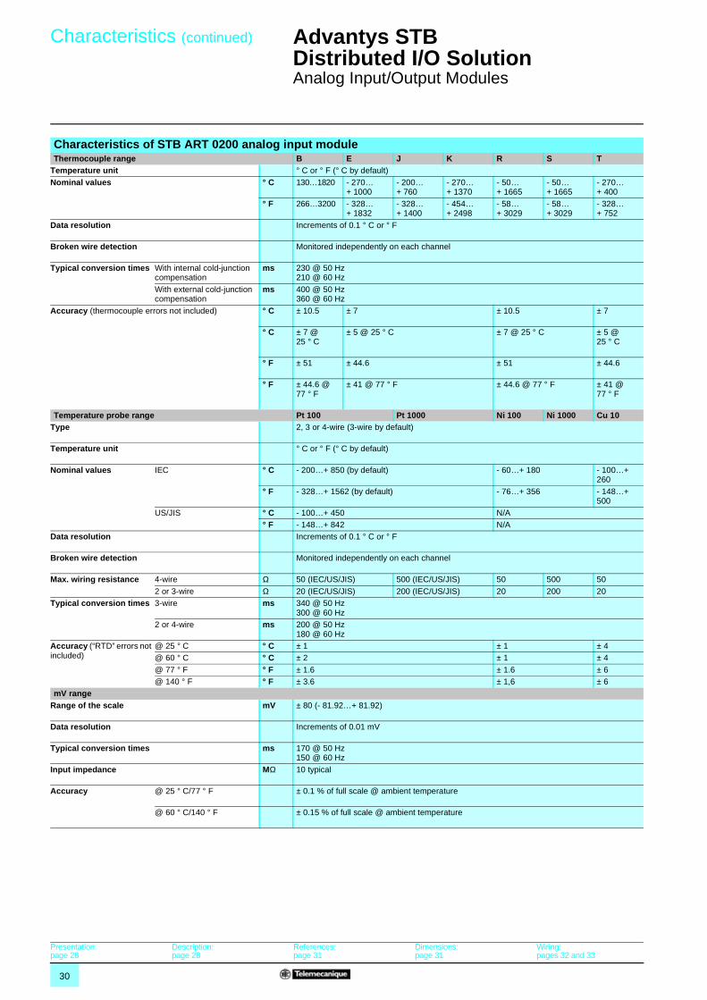
Characteristics of STB ART 0200 analog input module Thermocouple range B E J K R S T
Temperature unit ° C or ° F (° C by default)
Nominal values ° C 130…1820 - 270… + 1000
- 200… + 760
- 270… + 1370
- 50… + 1665
- 50… + 1665
- 270… + 400
° F 266…3200 - 328… + 1832
- 328… + 1400
- 454… + 2498
- 58… + 3029
- 58… + 3029
- 328… + 752
Data resolution Increments of 0.1 ° C or ° F
Broken wire detection Monitored independently on each channel
Typical conversion times With internal cold-junction compensation
ms 230 @ 50 Hz 210 @ 60 Hz
With external cold-junction compensation
ms 400 @ 50 Hz 360 @ 60 Hz
Accuracy (thermocouple errors not included) ° C ± 10.5 ± 7 ± 10.5 ± 7
° C ± 7 @ 25 ° C
± 5 @ 25 ° C ± 7 @ 25 ° C ± 5 @ 25 ° C
° F ± 51 ± 44.6 ± 51 ± 44.6
° F ± 44.6 @ 77 ° F
± 41 @ 77 ° F ± 44.6 @ 77 ° F ± 41 @ 77 ° F
Temperature probe range Pt 100 Pt 1000 Ni 100 Ni 1000 Cu 10Type 2, 3 or 4-wire (3-wire by default)
Temperature unit ° C or ° F (° C by default)
Nominal values IEC ° C - 200…+ 850 (by default) - 60…+ 180 - 100…+ 260
° F - 328…+ 1562 (by default) - 76…+ 356 - 148…+ 500
US/JIS ° C - 100…+ 450 N/A° F - 148…+ 842 N/A
Data resolution Increments of 0.1 ° C or ° F
Broken wire detection Monitored independently on each channel
Max. wiring resistance 4-wire Ω 50 (IEC/US/JIS) 500 (IEC/US/JIS) 50 500 50
2 or 3-wire Ω 20 (IEC/US/JIS) 200 (IEC/US/JIS) 20 200 20Typical conversion times 3-wire ms 340 @ 50 Hz
300 @ 60 Hz2 or 4-wire ms 200 @ 50 Hz
180 @ 60 HzAccuracy (“RTD” errors not included)
@ 25 ° C ° C ± 1 ± 1 ± 4@ 60 ° C ° C ± 2 ± 1 ± 4
@ 77 ° F ° F ± 1.6 ± 1.6 ± 6@ 140 ° F ° F ± 3.6 ± 1,6 ± 6
mV rangeRange of the scale mV ± 80 (- 81.92…+ 81.92)
Data resolution Increments of 0.01 mV
Typical conversion times ms 170 @ 50 Hz 150 @ 60 Hz
Input impedance MΩ 10 typical
Accuracy @ 25 ° C/77 ° F ± 0.1 % of full scale @ ambient temperature
@ 60 ° C/140 ° F ± 0.15 % of full scale @ ambient temperature
Presentation:page 28
Description:page 28
References:page 31
Dimensions:page 31
Wiring:pages 32 and 33
31
References,dimensions
Advantys STB Distributed I/O Solution 1
Analog Input/Output Modules
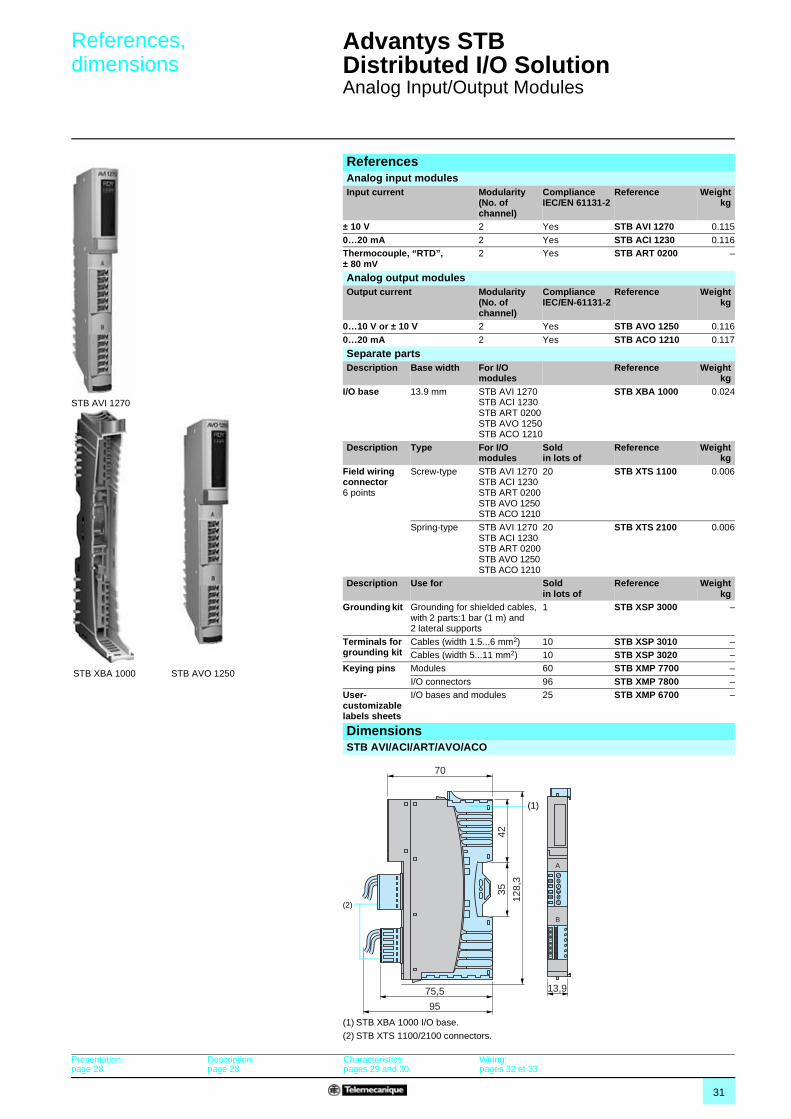
ReferencesAnalog input modulesInput current Modularity
(No. of channel)
Compliance IEC/EN 61131-2
Reference Weightkg
± 10 V 2 Yes STB AVI 1270 0.115
0…20 mA 2 Yes STB ACI 1230 0.116Thermocouple, “RTD”, ± 80 mV
2 Yes STB ART 0200 –
STB AVI 1270
Analog output modulesOutput current Modularity
(No. of channel)
Compliance IEC/EN-61131-2
Reference Weightkg
0…10 V or ± 10 V 2 Yes STB AVO 1250 0.116
0…20 mA 2 Yes STB ACO 1210 0.117
STB XBA 1000 STB AVO 1250
Separate partsDescription Base width For I/O
modulesReference Weight
kgI/O base 13.9 mm STB AVI 1270
STB ACI 1230STB ART 0200STB AVO 1250STB ACO 1210
STB XBA 1000 0.024
Description Type For I/O modules
Sold in lots of
Reference Weightkg
Field wiring connector 6 points
Screw-type STB AVI 1270STB ACI 1230STB ART 0200STB AVO 1250STB ACO 1210
20 STB XTS 1100 0.006
Spring-type STB AVI 1270STB ACI 1230STB ART 0200STB AVO 1250STB ACO 1210
20 STB XTS 2100 0.006
Description Use for Sold in lots of
Reference Weightkg
Grounding kit Grounding for shielded cables, with 2 parts:1 bar (1 m) and 2 lateral supports
1 STB XSP 3000 –
Terminals for grounding kit
Cables (width 1.5...6 mm2) 10 STB XSP 3010 –Cables (width 5...11 mm2) 10 STB XSP 3020 –
Keying pins Modules 60 STB XMP 7700 –
I/O connectors 96 STB XMP 7800 –User-customizable labels sheets
I/O bases and modules 25 STB XMP 6700 –
DimensionsSTB AVI/ACI/ART/AVO/ACO
(1) STB XBA 1000 I/O base.
(2) STB XTS 1100/2100 connectors.
70
75,5
95
4235
128,
3
(2)
(1)
A
B
13,9
Presentation:page 28
Description:page 28
Characteristics:pages 29 and 30
Wiring:pages 32 et 33
32
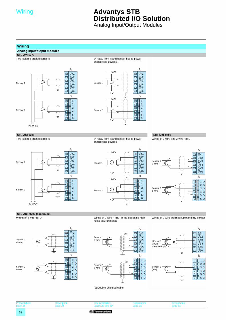
Wiring Advantys STB Distributed I/O Solution 1
Analog Input/Output Modules
WiringAnalog input/output modules STB AVI 1270
Two isolated analog sensors 24 VDC from island sensor bus to power analog field devices
STB ACI 1230 STB ART 0200Two isolated analog sensors 24 VDC from island sensor bus to power
analog field devicesWiring of 2-wire and 3-wire “RTD”
STB ART 0200 (continued)Wiring of 4-wire “RTD” Wiring of 2-wire “RTD” in the operating high
noise environmentsWiring of 2-wire thermocouple and mV sensor
(1) Double-shielded cable
A
B
123456
123456
+
+
–U
+
–
–
U
24 VDC
Sensor 1
Sensor 2
A
B
123456
123456
+
c 24 V
0 V
–U
+
c 24 V
0 V
–U
Sensor 1
Sensor 2
A
B
123456
123456
+
–
+
–
+ –24 VDC
I
I
Sensor 1
Sensor 2
A
B
123456
123456
+
c 24 V
0 V
–I
+
c 24 V
0 V
–I
Sensor 1
Sensor 2
123456
A
B
123456
U
U
Sensor 12-wire
Sensor 23-wire
123456
A
B
123456
U
U
Sensor 14-wire
Sensor 24-wire
A
B
123456
U
U
123456
Sensor 12-wire
Sensor 22-wire
(1)
(1) 123456
A
B
123456
Tc+
–
U
Sensor 12-wire thermocouple
Sensor 2(mV)
Presentation:page 28
Description:page 28
Characteristics:pages 29 and 30
References:page 31
Dimensions:page 31
33
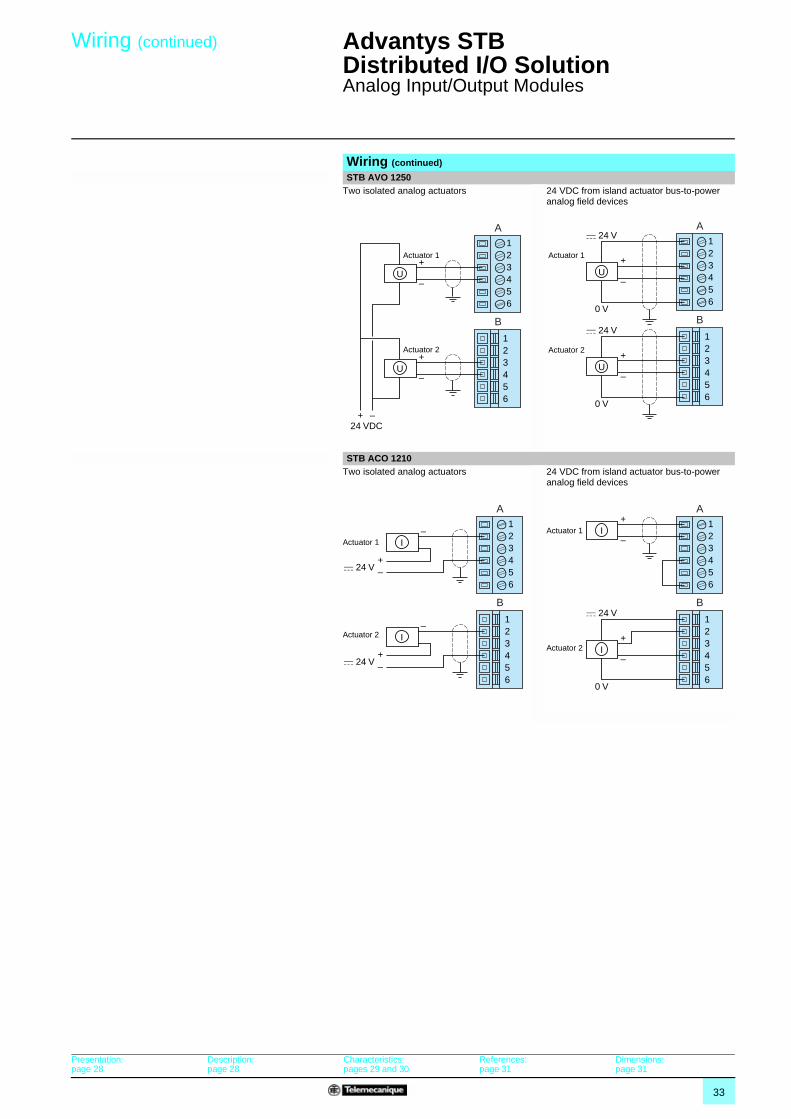
Wiring (continued) Advantys STB Distributed I/O Solution 1
Analog Input/Output Modules
Wiring (continued)
STB AVO 1250Two isolated analog actuators 24 VDC from island actuator bus-to-power
analog field devices
STB ACO 1210Two isolated analog actuators 24 VDC from island actuator bus-to-power
analog field devices
A
B
123456
123456
+
+
–U
+
–
–
U
24 VDC
Actuator 1
Actuator 2
A
B
123456
123456
+
c 24 V
0 V
–U
+
c 24 V
0 V
–U
Actuator 1
Actuator 2
A
B
123456
123456
–
–+
c 24 V
I
–
–+
c 24 V
I
Actuator 1
Actuator 2
A
B
123456
123456
+
c 24 V
0 V
–I
+
–IActuator 1
Actuator 2
Presentation:page 28
Description:page 28
Characteristics:pages 29 and 30
References:page 31
Dimensions:page 31
34
Presentation,description,dimensions
Advantys STB Distributed I/O Solution 1
Parallel Interface for Tego Power Applications
The STB EPI 1145 parallel interface is a component of the Advantys STB island designed for the remote connection of 8 motor-starters (or 4 motor-starters in both directions). These TeSys model d motor-starters use the Tego Power installation assistance system.
Tego Power is a modular system to help install TeSys model d motor-starters by offering prewired control and power circuits. This Quickfit technology enables cable-free connections to spring-loaded contactor terminals, model d (9 to 32 A) and GV2 M2 motor circuit-breakers.
Tego Power with Quickfit technology enables you to create motor-starter assemblies up to 15 kW/400 V.
The Tego Power system differentiates the power section from the control section:
b The power kit comprises:v a specific plate used to assemble 2 to 8 motor-starters, v two connection modules,v a power splitter box with a power terminal block, The contactor for each motor-starter is activated by one of the 8 outputs of the STB EPI 1145 parallel interface.b The control kit comprises:v a control splitter box for the 2 to 8 motor-starters,v a connection module. The 2 return outputs of each motor-starter (contactor status, circuit-breaker status) are connected to 2 of the 16 inputs to the STB EPI 1145 parallel interface.
The STB EPI 1145 parallel interface comprises: 1 A display block with 8 LEDs indicating the state of the various motor-starters or
output devices.2 A location for a user-customizable label.3 A color-coded module identification stripe (black).4 Selection switch used to view each motor-starter state. 5 An HE 10 connector (30-pin) to connect to a Tego Power system via
STB XCA 3002/3003 cables.
To be ordered separately: An STB XBA 2000 base, width 18.4 mm. The base features a location for the user-customizable label.
(1) With HE 10 connector (30-pin).
Presentation
1
2 3
4
The Tego Power System
Structure of the Tego Power System
Description
1
2
4
5
3
DimensionsSTB EPI 1145
102,7 (1)
70
4235 12
05
18,4
Characteristics:page 35
References:page 35
1 63 A power splitter box2 Control splitter box3 Connection cable4 Connection control module
35
Characteristics,references
Advantys STB Distributed I/O Solution 1
Parallel Interface for Tego Power Applications
(1) For other Tego Power components, refer to our catalog: “Motor-starter solutions, control and power protection components”.
(2) For a set of 8 motor-starters, use 2 APP 2R4E splitter boxes.
CharacteristicsElectrical characteristicsModule Type STB EPI 1145
Plug in/plug out with power on YesConnection Via 1 HE 10 connector (30 contacts).
P/S Via STB PDT 3100 c 24 V power distribution moduleProtection Via STB PDT 3100 power distribution module fuseConsumption On c 5 V logic bus mA 130
On c 24 V sensor bus mA max. 100On c 24 V actuator bus mA max. 50 (with all 8 outputs at 0 state), max. 1,000 (with all 8 outputs at 1 state)
Characteristics of inputsNumber 16 (8 for the status of each contactor/ 8 for the status of each circuit-breaker)Nominal values Voltage c V 24
Type IEC/EN 61131-2 Type 1Limit values At state 1 Voltage V 15...30
Current mA min. 2
At state 0 Voltage V - 3...+ 5Current mA max. 0.5
Protection Resistor-limited
Characteristics of outputsNumber 8 (8 to control each contactor)
Nominal values Voltage c V 24Current mA 100 per channel, 850 per module
Limit values Permanent voltage V 19.2...30
Absolute voltage V 36Peak voltage A 1 for 100 µs per channel
Max. loads Capacity µF 50Inductance 0.5 Henry at 4 Hz
Short circuit and overload protection Yes, per channel
ReferencesParallel interface for TeSys model d motor-starters with Tego Power systemPower Supply type
Voltage Reference Weightkg
c 24 V STB EPI 1145 0,120
STB EPI 1145STB XBA 2000
Separate partsDescription Use Sold in lots of Reference Weight
kgBase 18.4 mm Application-specific
module mounted on DIN rail
1 STB XBA 2000 0.024
Keying pin For application-specific module
60 STB XMP 7700 –
User-customizable labels sheets
Customization of modules and bases
25 STB XMP 6700 –
Description Use Length Reference Weightkg
Connection cables (30-pin at each end)
From the power splitter box and APP 2RpE control to the STB EPI 1145 module
1 m STB XCA 3002 –
2 m STB XCA 3003 –
Tego Power separate elements (1)
Description Use Reference Weightkg
Power and control splitter boxes
2 outputs APP 2R2E –
4 outputs (2) APP 2R4E –
Presentation:page 34
Description:page 34
Dimensions:page 34
36
Presentation,description,dimensions
Advantys STB Distributed I/O Solution 1
Parallel Interface for TeSys Model U Applications
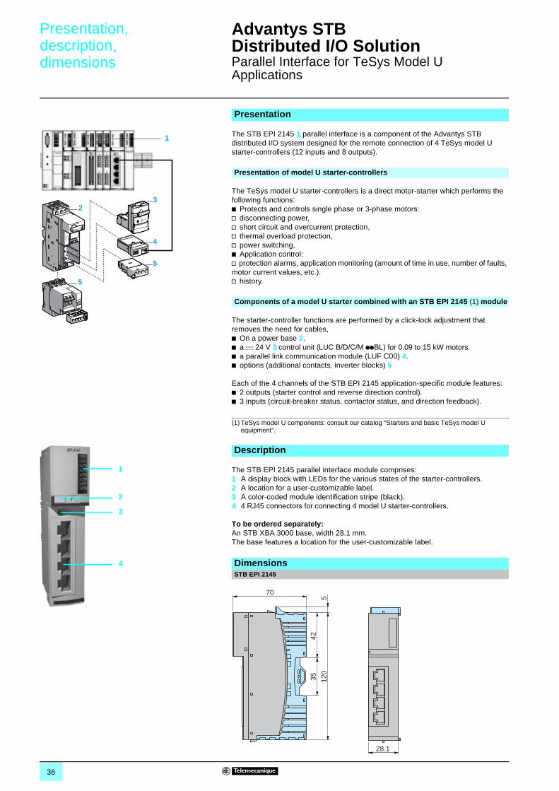
The STB EPI 2145 1 parallel interface is a component of the Advantys STB distributed I/O system designed for the remote connection of 4 TeSys model U starter-controllers (12 inputs and 8 outputs).
The TeSys model U starter-controllers is a direct motor-starter which performs the following functions:b Protects and controls single phase or 3-phase motors:v disconnecting power,v short circuit and overcurrent protection,v thermal overload protection,v power switching,b Application control:v protection alarms, application monitoring (amount of time in use, number of faults, motor current values, etc.).v history.
The starter-controller functions are performed by a click-lock adjustment that removes the need for cables,b On a power base 2.b a c 24 V 3 control unit (LUC B/D/C/M ppBL) for 0.09 to 15 kW motors.b a parallel link communication module (LUF C00) 4.b options (additional contacts, inverter blocks) 5
Each of the 4 channels of the STB EPI 2145 application-specific module features: b 2 outputs (starter control and reverse direction control).b 3 inputs (circuit-breaker status, contactor status, and direction feedback).
(1) TeSys model U components: consult our catalog “Starters and basic TeSys model U equipment”.
The STB EPI 2145 parallel interface module comprises: 1 A display block with LEDs for the various states of the starter-controllers.2 A location for a user-customizable label. 3 A color-coded module identification stripe (black).4 4 RJ45 connectors for connecting 4 model U starter-controllers.
To be ordered separately: An STB XBA 3000 base, width 28.1 mm. The base features a location for the user-customizable label.
Presentation
5
23
4
5
1
Presentation of model U starter-controllers
Components of a model U starter combined with an STB EPI 2145 (1) module
Description
1
2
4
3
DimensionsSTB EPI 2145
70
4235 12
05
28.1
37
Characteristics,references
Advantys STB Distributed I/O Solution 1
Parallel Interface for TeSys Model U Applications
CharacteristicsModule Type STB EPI 2145
Hot swapping Yes
Connection Via 4 RJ45 connectorsPower Supply Via STB PDT 3100 c 24 V power distribution moduleProtection Via STB PDT 3100 power distribution module fuse
Consumption On c 5 V logic bus mA 130On c 24 V sensor bus mA max. 100On c 24 V actuator bus mA max. 50 (with all 8 outputs at 0 state), max. 1,000 (with all 8 outputs at 1 state)
Characteristics of InputsNumber of inputs 12
Nominal values Voltage c V 24Type Type IEC/EN61131-2 Type 1Limit values At state 1 Voltage V 15...30
Current mA min. 2At state 0 Voltage V - 3...+ 5
Current mA max. 0.5
Protection Resistor-limited
Characteristics of OutputsNumber of outputs 8Nominal values Voltage c V 24
Current mA 100 per channel, 850 per module
Limit values Permanent voltage V 19.2...30Absolute voltage V 36Peak voltage A 1 for 100 µs per channel
Max. loads Capacity µF 50Inductance 0.5 Henry at 4 Hz
Short circuit and overload protection Yes, per channel
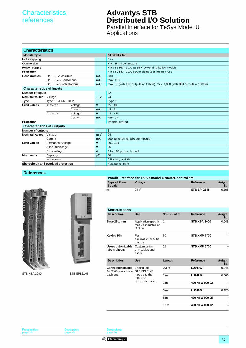
ReferencesParallel Interface for TeSys model U starter-controllersType of Power Supply
Voltage Reference Weightkg
c 24 V STB EPI 2145 0.165
STB EPI 2145STB XBA 3000
Separate partsDescription Use Sold in lot of Reference Weight
kgBase 28.1 mm Application-specific
module mounted on DIN rail
1 STB XBA 3000 0.048
Keying Pin For application-specific module
60 STB XMP 7700 –
User-customizable labels sheets
Customization of modules and bases
25 STB XMP 6700 –
Description Use Length Reference Weightkg
Connection cablesAn RJ45 connector at each end
Linking the STB EPI 2145 module to the model U starter-controller
0.3 m LU9 R03 0.045
1 m LU9 R10 0.065
2 m 490 NTW 000 02 –
3 m LU9 R30 0.125
5 m 490 NTW 000 05 –
12 m 490 NTW 000 12 –
Presentation:page 36
Description:page 36
Dimensions:page 36
38
Presentation,description
Advantys STB Distributed I/O Solution 1
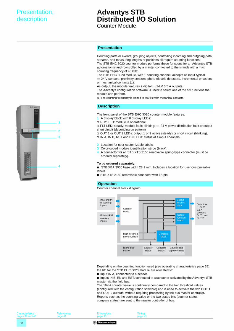
Counter Module
Counting parts or events, grouping objects, controlling incoming and outgoing data streams, and measuring lengths or positions all require counting functions.The STB EHC 3020 counter module performs these functions for an Advantys STB automation island (controlled by a master connected to the island) with a max. counting frequency of 40 kHz.The STB EHC 3020 module, with 1 counting channel, accepts as input typical c 24 V sensors: proximity sensors, photo-electric detectors, incremental encoders or mechanical contacts (1). As output, the module features 2 digital c 24 V 0.5 A outputs.The Advantys configuration software is used to select one of the six functions the module can perform. (1) The counting frequency is limited to 400 Hz with mecanical contacts.
The front panel of the STB EHC 3020 counter module features: 1 A display block with 8 display LEDs:v RDY LED: module is operational,v FLT LED: steady: module fault; blinking: c 24 V power distribution fault or output short circuit (depending on pattern)v OUT 1 or OUT 2 LEDs: output 1 or 2 active (steady) or short circuit (blinking),v IN A, IN B, RST and EN LEDs: status of 4 input channels.
2 Location for user-customizable labels.3 Color-coded module identification stripe (black).4 A connector for an STB XTS 2150 removable spring-type connector (must be
ordered separately).
To be ordered separately:b STB XBA 3000 base width 28.1 mm. Includes a location for user-customizable labels.b STB XTS 2150 removable connector with 18-pin.
Counter channel block diagram
Depending on the counting function used (see operating characteristics page 39), the I/O for the STB EHC 3020 module are allocated to:b Input IN A, connected to a sensor.b Inputs IN B, EN and RST, connected to a sensor or activated by the Advantys STB master via the field bus.The 16-bit counter value is continually compared to the two threshold values (configured with the configuration software) and is used to activate the two OUT 1 and OUT 2 outputs, without requiring processing by the bus master controller. Reports such as the counting value or the two status bits (counter status, compare status) are sent to the master controller of bus.
Presentation
Description
1
2
3
4
Operation
IN A and IN B counting inputs
Output function block
Compare block
EN and RST auxiliary inputs
Output for c 24 V 0.5 A counters OUT 1 and OUT 2
Counter status
High thresholdLow threshold
Island bus master
Counter block
Output function block
Compare status
Counter and capture values
Characteristics:pages 39 and 40
References:page 41
Dimensions:page 41
Wiring:page 41
39
Characteristics Advantys STB Distributed I/O Solution 1
Counter Module
Functional characteristicsConfigurable functions Number 1 of the 6 configurable functions (using the Advantys configuration software)
Frequency meter This function measures the frequency received on the IN A input. This frequency is always expressed in Hz (number of pulses per second), with a precision of 1 hertz.Also measures the speed in Units per second. The number of points to be received on the IN A input, corresponding to one unit, must be defined from one up to 255. The maximal frequency on the IN A input is 40 kHz in both cases (without filtering).Response time: < 0,2 s (frequency 2/40 kHz), < 1 s (frequency 0,2 kHz).
Count events This function provides the value of the number of pulses received on the IN A input during a selectable time unit. The time unit is configurable : 0.1s, 1s, 10 s or 1 minute.The IN B input can be used to reset the internal time basis which provides the time unit. The maximal number of pulses counted during a time unit is up to 65535.The minimal pulses duration on the IN A input is 10 µs (without filtering).Response time: < 0,5 ms
Measure time periods Measures the elapsed time during an event or between two evens (on IN A input) according to the selectable time base of 10 µs, 100 µs or 1 ms. The max. event duration is 0.655, 6.55, or 65.5 seconds, respectively. The max. frequency on the IN A input is 200 Hz.Response time: < 0.5 ms.
Down counting The IN B input starts or restarts the counter by resetting the setpoint value defined by the high threshold value. When the counter is running , any pulse received on the IN A input decreases the counter.The counter stops when it reaches 0.The setpoint maximal value is 65535.The maximal frequency on the IN A input is 40 kHz (without filtering).Response time : < 0,5 ms
Loop (modulo) counting The IN B input starts or restarts the counter by resetting the setpoint value to 0. The IN B input also triggers the capture of the previous counting value before the counter is reset to 0. When the counter is running , any pulse received on the IN A input increases the counter.The counter turns back to zero automatically when the pulse number received equals the modulo defined by the high threshold value.The modulo maximal value is 65535.The maximal frequency on the IN A input is 40 kHz (without filtering).Response time : < 0,5 ms
Up/down counting The RST input starts or restarts the counter by resetting the preset value. When the counter is running, the counting increases or decreseases according to the pulses received on the IN A and IN B inputs (default settings : IN A increases the counter and IN B decreases the counter). By configuration: v the IN B input can define the counting direction of the pulses received on IN A.v the IN A and IN B inputs can receivet the signals of an incremental encoder.
The counter value is limited to 0 as low limit and to 65535 as high limit.Response time : < 0,5 ms
OUT 1 and OUT 2 output functions According to requirements, each of the counting module’s two outputs can be configured for one of the following operating modes:v No direct action: the counter status and status words are processed by the island masterv The output is activated when the counter value is less than the low thresholdv The output is activated when the counter value is between the low threshold and the high
thresholdv The output is activated when the counter value is greater than the high thresholdv A pulse is generated on the output when the low threshold is exceeded (when counting
down)v A pulse is generated on the output when the low threshold is exceeded (when counting up)v A pulse is generated on the output when the high threshold is exceeded (when counting
down)v A pulse is generated on the output when the high threshold is exceeded (when counting up)v The output is activated as long as the counter is RUN (only available on downcouting
function)v The output is activated when the counter is STOPv The output is activated when the capture value is less than the low threshold (only available
on modulo function)v The output is activated (according to the modulo) when the counter value is between the low
threshold and the high threshold
Presentation:page 38
Description:page 38
References:page 41
Dimensions:page 41
Wiring:page 41
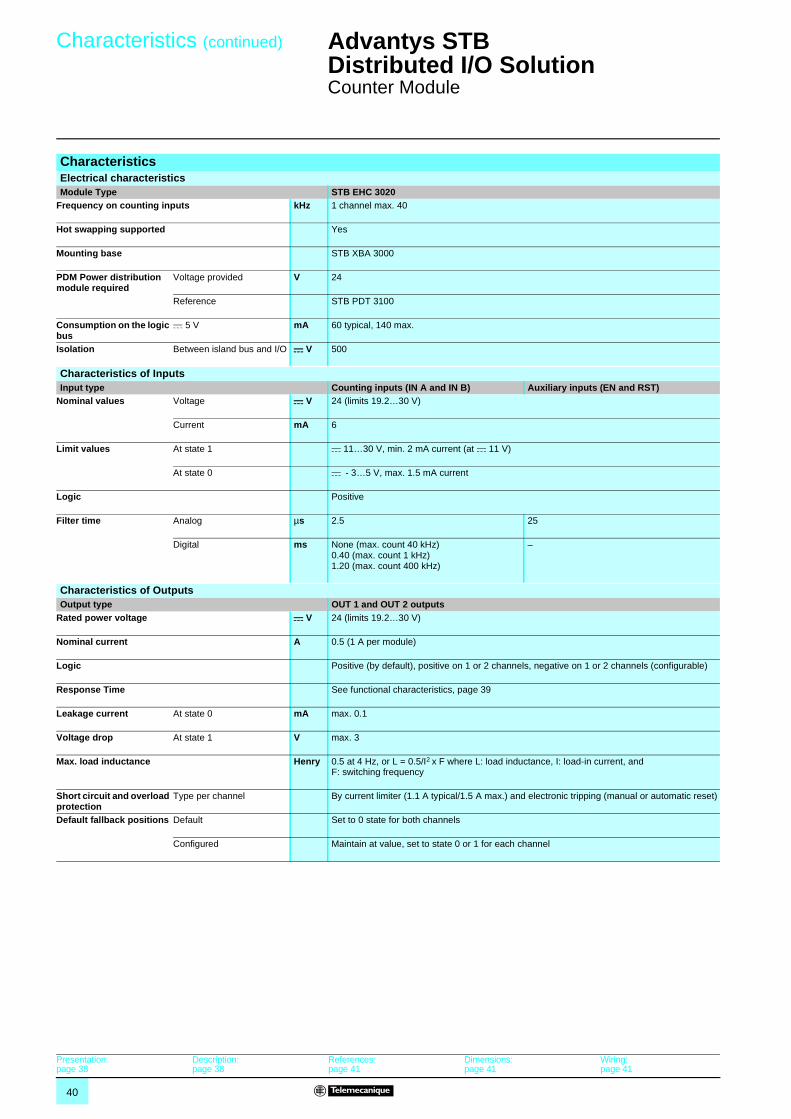
40
Characteristics (continued) Advantys STB Distributed I/O Solution 1
Counter Module
CharacteristicsElectrical characteristicsModule Type STB EHC 3020
Frequency on counting inputs kHz 1 channel max. 40
Hot swapping supported Yes
Mounting base STB XBA 3000
PDM Power distribution module required
Voltage provided V 24
Reference STB PDT 3100
Consumption on the logic bus
c 5 V mA 60 typical, 140 max.
Isolation Between island bus and I/O c V 500
Characteristics of InputsInput type Counting inputs (IN A and IN B) Auxiliary inputs (EN and RST)
Nominal values Voltage c V 24 (limits 19.2…30 V)
Current mA 6
Limit values At state 1 c 11…30 V, min. 2 mA current (at c 11 V)
At state 0 c - 3…5 V, max. 1.5 mA current
Logic Positive
Filter time Analog µs 2.5 25
Digital ms None (max. count 40 kHz)0.40 (max. count 1 kHz)1.20 (max. count 400 kHz)
–
Characteristics of OutputsOutput type OUT 1 and OUT 2 outputs
Rated power voltage c V 24 (limits 19.2…30 V)
Nominal current A 0.5 (1 A per module)
Logic Positive (by default), positive on 1 or 2 channels, negative on 1 or 2 channels (configurable)
Response Time See functional characteristics, page 39
Leakage current At state 0 mA max. 0.1
Voltage drop At state 1 V max. 3
Max. load inductance Henry 0.5 at 4 Hz, or L = 0.5/I2 x F where L: load inductance, I: load-in current, and F: switching frequency
Short circuit and overload protection
Type per channel By current limiter (1.1 A typical/1.5 A max.) and electronic tripping (manual or automatic reset)
Default fallback positions Default Set to 0 state for both channels
Configured Maintain at value, set to state 0 or 1 for each channel
Presentation:page 38
Description:page 38
References:page 41
Dimensions:page 41
Wiring:page 41
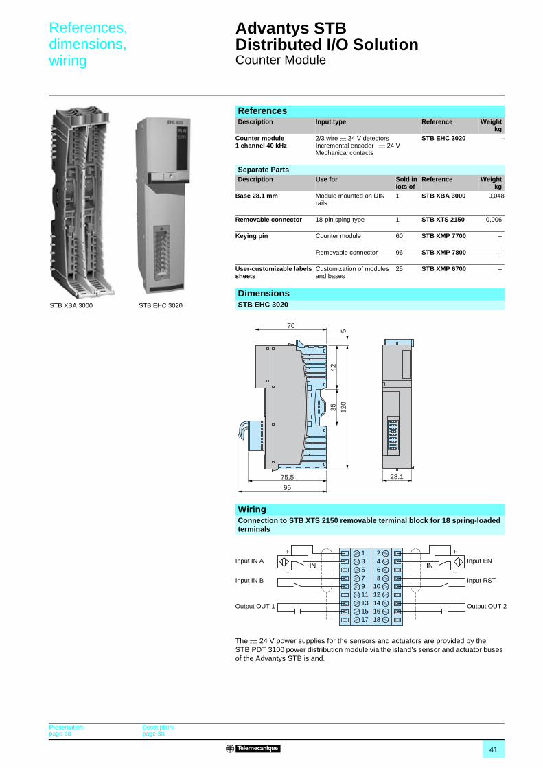
41
References,dimensions,wiring
Advantys STB Distributed I/O Solution 1
Counter Module
The c 24 V power supplies for the sensors and actuators are provided by the STB PDT 3100 power distribution module via the island’s sensor and actuator buses of the Advantys STB island.
ReferencesDescription Input type Reference Weight
kgCounter module 1 channel 40 kHz
2/3 wire c 24 V detectorsIncremental encoder c 24 VMechanical contacts
STB EHC 3020 –
STB EHC 3020STB XBA 3000
Separate PartsDescription Use for Sold in
lots ofReference Weight
kgBase 28.1 mm Module mounted on DIN
rails1 STB XBA 3000 0,048
Removable connector 18-pin sping-type 1 STB XTS 2150 0,006
Keying pin Counter module 60 STB XMP 7700 –
Removable connector 96 STB XMP 7800 –
User-customizable labels sheets
Customization of modules and bases
25 STB XMP 6700 –
DimensionsSTB EHC 3020
28.1
7042
35 120
5
75.5
95
WiringConnection to STB XTS 2150 removable terminal block for 18 spring-loaded terminals
+
IN IN–
1357911131517
+
–
2468
1012141618
Input IN A
Input IN B
Output OUT 1
Input EN
Input RST
Output OUT 2
Presentation:page 38
Description:page 38
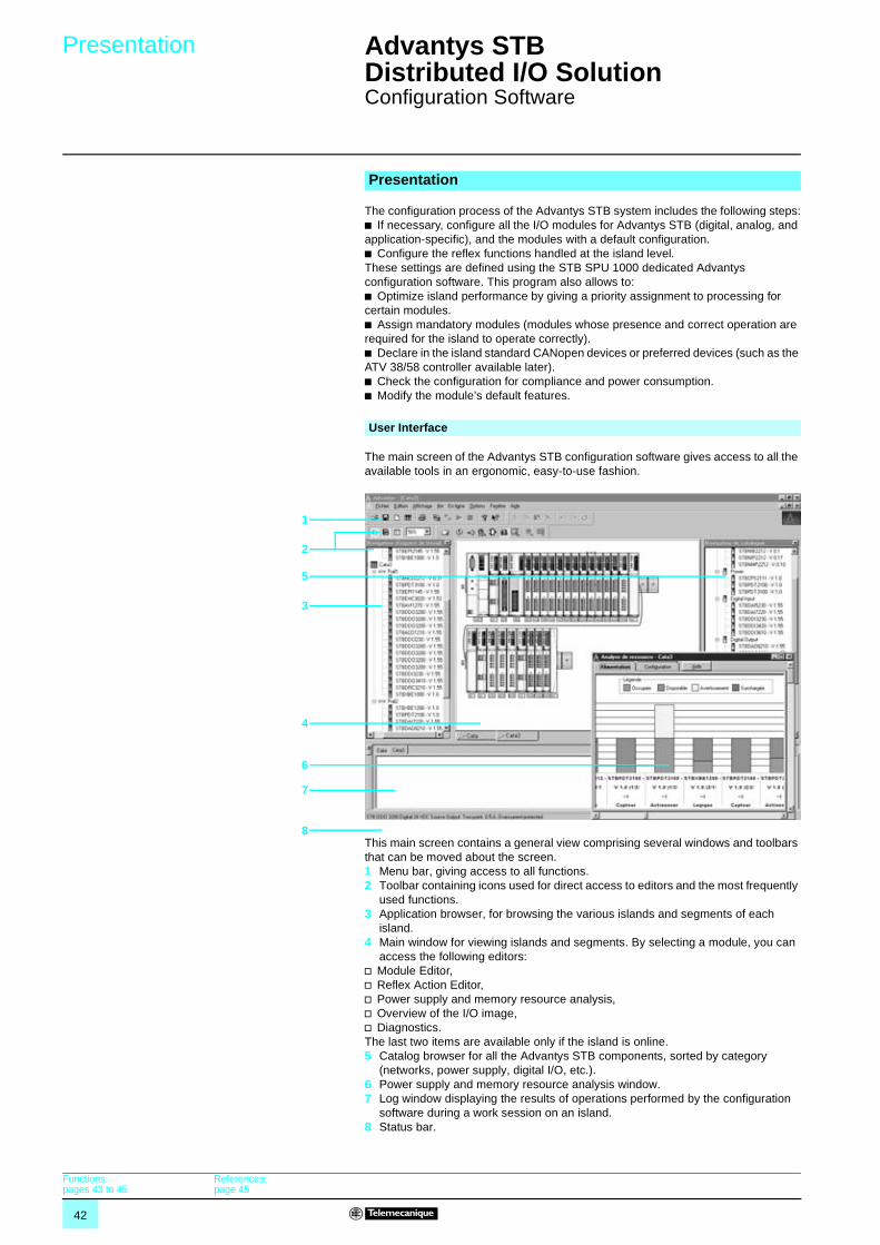
42
Presentation Advantys STB Distributed I/O Solution 1
Configuration Software
The configuration process of the Advantys STB system includes the following steps:b If necessary, configure all the I/O modules for Advantys STB (digital, analog, and application-specific), and the modules with a default configuration.b Configure the reflex functions handled at the island level.These settings are defined using the STB SPU 1000 dedicated Advantys configuration software. This program also allows to:b Optimize island performance by giving a priority assignment to processing for certain modules.b Assign mandatory modules (modules whose presence and correct operation are required for the island to operate correctly).b Declare in the island standard CANopen devices or preferred devices (such as the ATV 38/58 controller available later).b Check the configuration for compliance and power consumption.b Modify the module’s default features.
The main screen of the Advantys STB configuration software gives access to all the available tools in an ergonomic, easy-to-use fashion.
This main screen contains a general view comprising several windows and toolbars that can be moved about the screen.1 Menu bar, giving access to all functions.2 Toolbar containing icons used for direct access to editors and the most frequently
used functions.3 Application browser, for browsing the various islands and segments of each
island.4 Main window for viewing islands and segments. By selecting a module, you can
access the following editors:v Module Editor,v Reflex Action Editor,v Power supply and memory resource analysis,v Overview of the I/O image,v Diagnostics.The last two items are available only if the island is online.5 Catalog browser for all the Advantys STB components, sorted by category
(networks, power supply, digital I/O, etc.).6 Power supply and memory resource analysis window.7 Log window displaying the results of operations performed by the configuration
software during a work session on an island.8 Status bar.
Presentation
User Interface
Functions:pages 43 to 45
References:page 45
1
2
5
3
4
6
7
8
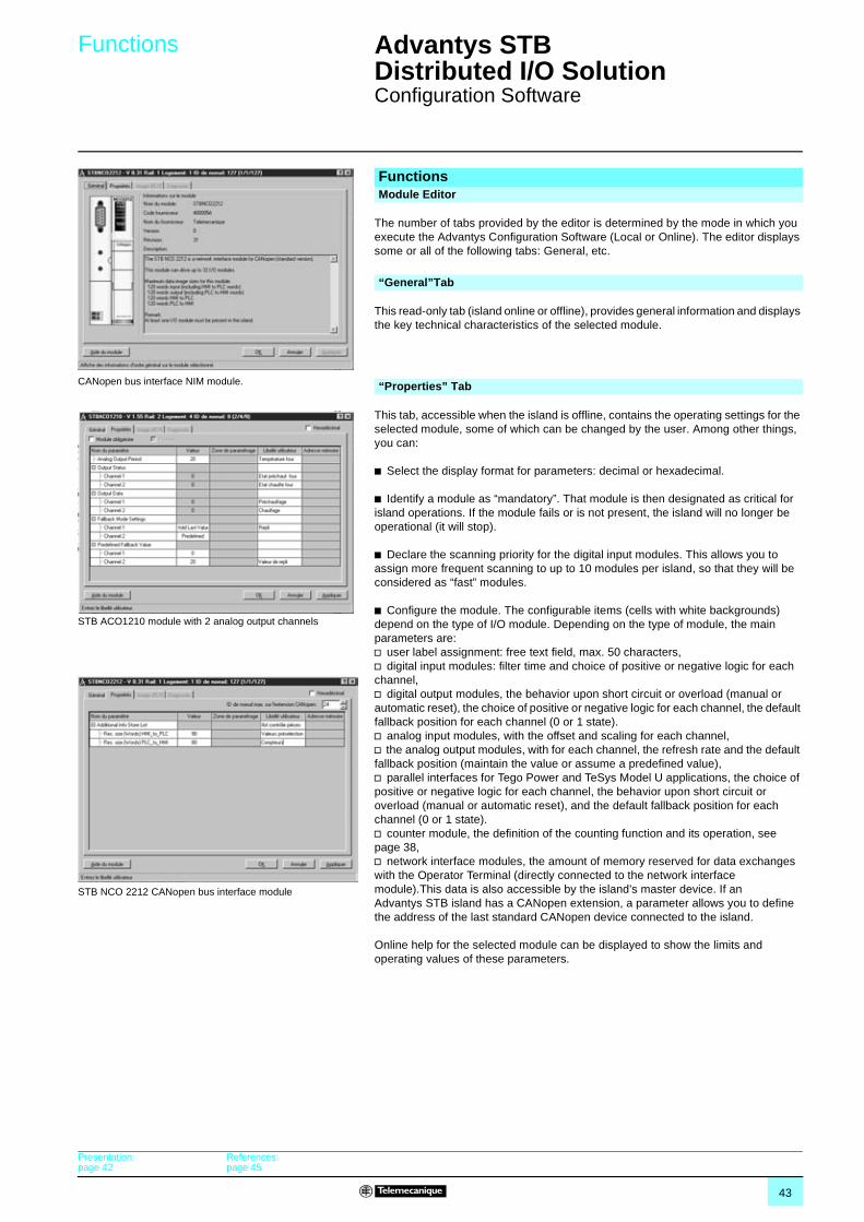
43
Functions Advantys STB Distributed I/O Solution 1
Configuration Software
The number of tabs provided by the editor is determined by the mode in which you execute the Advantys Configuration Software (Local or Online). The editor displays some or all of the following tabs: General, etc.
This read-only tab (island online or offline), provides general information and displays the key technical characteristics of the selected module.
This tab, accessible when the island is offline, contains the operating settings for the selected module, some of which can be changed by the user. Among other things, you can:
b Select the display format for parameters: decimal or hexadecimal.
b Identify a module as “mandatory”. That module is then designated as critical for island operations. If the module fails or is not present, the island will no longer be operational (it will stop).
b Declare the scanning priority for the digital input modules. This allows you to assign more frequent scanning to up to 10 modules per island, so that they will be considered as “fast” modules.
b Configure the module. The configurable items (cells with white backgrounds) depend on the type of I/O module. Depending on the type of module, the main parameters are: v user label assignment: free text field, max. 50 characters,v digital input modules: filter time and choice of positive or negative logic for each channel,v digital output modules, the behavior upon short circuit or overload (manual or automatic reset), the choice of positive or negative logic for each channel, the default fallback position for each channel (0 or 1 state).v analog input modules, with the offset and scaling for each channel,v the analog output modules, with for each channel, the refresh rate and the default fallback position (maintain the value or assume a predefined value),v parallel interfaces for Tego Power and TeSys Model U applications, the choice of positive or negative logic for each channel, the behavior upon short circuit or overload (manual or automatic reset), and the default fallback position for each channel (0 or 1 state).v counter module, the definition of the counting function and its operation, see page 38,v network interface modules, the amount of memory reserved for data exchanges with the Operator Terminal (directly connected to the network interface module).This data is also accessible by the island’s master device. If an Advantys STB island has a CANopen extension, a parameter allows you to define the address of the last standard CANopen device connected to the island.
Online help for the selected module can be displayed to show the limits and operating values of these parameters.
FunctionsModule Editor
CANopen bus interface NIM module.
“General”Tab
“Properties” Tab
STB ACO1210 module with 2 analog output channels
STB NCO 2212 CANopen bus interface module
Presentation:page 42
References:page 45
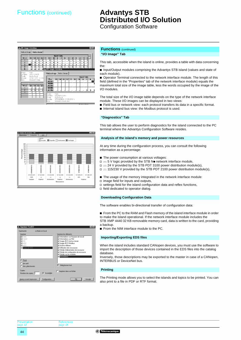
44
Functions (continued) Advantys STB Distributed I/O Solution 1
Configuration Software
This tab, accessible when the island is online, provides a table with data concerning the:b Input/Output modules comprising the Advantys STB island (values and state of each module). b Operator Terminal connected to the network interface module. The length of this field (defined in the “Properties” tab of the network interface module) equals the maximum total size of the image table, less the words occupied by the image of the I/O modules.
The total size of the I/O image table depends on the type of the network interface module. These I/O images can be displayed in two views:b Field bus or network view: each protocol transfers its data in a specific format.b Internal island bus view: the Modbus protocol is used.
This tab allows the user to perform diagnostics for the island connected to the PC terminal where the Advantys Configuration Software resides.
At any time during the configuration process, you can consult the following information as a percentage:
b The power consumption at various voltages:v c 5 V logic provided by the STB Np network interface module, v c 24 V provided by the STB PDT 3100 power distribution module(s), v c 115/230 V provided by the STB PDT 2100 power distribution module(s),
b The usage of the memory integrated in the network interface module:v image field for inputs and outputs,v settings field for the island configuration data and reflex functions,v field dedicated to operator dialog.
The software enables bi-directional transfer of configuration data:
b From the PC to the RAM and Flash memory of the island interface module in order to make the island operational. If the network interface module includes the STB XMP 4440 32 KB removable memory card, data is written to the card, providing a backup.b From the NIM interface module to the PC.
When the island includes standard CANopen devices, you must use the software to import the description of those devices contained in the EDS files into the catalog database. Inversely, those descriptions may be exported to the master in case of a CANopen, INTERBUS or DeviceNet bus.
The Printing mode allows you to select the islands and topics to be printed. You can also print to a file in PDF or RTF format.
Functions (continued)
“I/O Image” Tab
“Diagnostics” Tab
Analysis of the island’s memory and power resources
Downloading Configuration Data
Importing/Exporting EDS files
Printing
Presentation:page 42
References:page 45
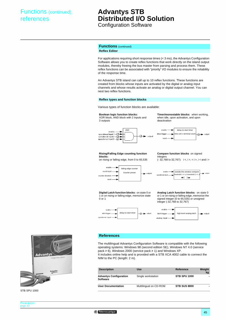
45
Functions (continued),
referencesAdvantys STB Distributed I/O Solution 1
Configuration Software
For applications requiring short response times (< 3 ms), the Advantys Configuration Software allows you to create reflex functions that work directly on the island output modules, thereby freeing the bus master from parsing and process them. These reflex functions can be associated with “priority” I/O modules to ensure the reliability of the response time.
An Advantys STB island can call up to 10 reflex functions. These functions are created from blocks whose inputs are activated by the digital or analog input channels and whose results activate an analog or digital output channel. You can nest two reflex functions.
Various types of function blocks are available:
The multilingual Advantys Configuration Software is compatible with the following operating systems: Windows 98 (second edition SE), Windows NT 4.0 (service pack u 6), Windows 2000 (service pack u 1) and Windows XP. It includes online help and is provided with a STB XCA 4002 cable to connect the NIM to the PC (length: 2 m).
Functions (continued)
Reflex Editor
Reflex types and function blocks
Boolean logic function blocks: XOR block, AND block with 2 inputs and 3 outputs
Timer/monostable blocks: when working, when idle, upon activation, and upon deactivation
Rising/Falling Edge counting function blocks: on rising or falling edge, from 0 to 65,535
Compare function blocks on signed integers (- 32,768 to 32,767): i <, i >, < i >, i < and i >
Digital Latch function blocks: on state 0 or 1 or on rising or falling edge, memorize state 0 or 1
Analog Latch function blocks: on state 0 or 1 or on rising or falling edge, memorize the signed integer (0 to 65,535) or unsigned integer (-32,768 to 32,767)
AND delay-to-start timer
time unit x terminal count
falling-edge counter
counter preset outside-the-window compare threshold 1 +/- ∆ threshold 2 +/- ∆
delay-to-start timer high-level analog-latch
References
Description Use Reference Weightkg
Advantys Configuration Software
Single workstation STB SPU 1000 –
User Documentation Multilingual on CD-ROM STB SUS 8800 –
STB SPU 1000
Presentation:page 42
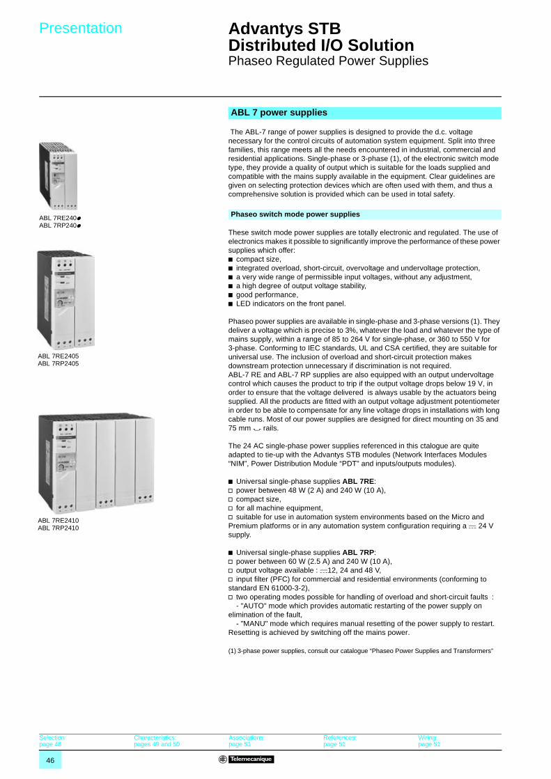
46
Presentation Advantys STB Distributed I/O Solution 1
Phaseo Regulated Power Supplies
The ABL-7 range of power supplies is designed to provide the d.c. voltage necessary for the control circuits of automation system equipment. Split into three families, this range meets all the needs encountered in industrial, commercial and residential applications. Single-phase or 3-phase (1), of the electronic switch mode type, they provide a quality of output which is suitable for the loads supplied and compatible with the mains supply available in the equipment. Clear guidelines are given on selecting protection devices which are often used with them, and thus a comprehensive solution is provided which can be used in total safety.
These switch mode power supplies are totally electronic and regulated. The use of electronics makes it possible to significantly improve the performance of these power supplies which offer:b compact size,b integrated overload, short-circuit, overvoltage and undervoltage protection,b a very wide range of permissible input voltages, without any adjustment,b a high degree of output voltage stability,b good performance,b LED indicators on the front panel. Phaseo power supplies are available in single-phase and 3-phase versions (1). They deliver a voltage which is precise to 3%, whatever the load and whatever the type of mains supply, within a range of 85 to 264 V for single-phase, or 360 to 550 V for 3-phase. Conforming to IEC standards, UL and CSA certified, they are suitable for universal use. The inclusion of overload and short-circuit protection makes downstream protection unnecessary if discrimination is not required. ABL-7 RE and ABL-7 RP supplies are also equipped with an output undervoltage control which causes the product to trip if the output voltage drops below 19 V, in order to ensure that the voltage delivered is always usable by the actuators being supplied. All the products are fitted with an output voltage adjustment potentiometer in order to be able to compensate for any line voltage drops in installations with long cable runs. Most of our power supplies are designed for direct mounting on 35 and 75 mm 7 rails.
The 24 AC single-phase power supplies referenced in this ctalogue are quite adapted to tie-up with the Advantys STB modules (Network Interfaces Modules “NIM”, Power Distribution Module “PDT” and inputs/outputs modules).
b Universal single-phase supplies ABL 7RE: v power between 48 W (2 A) and 240 W (10 A),v compact size,v for all machine equipment,v suitable for use in automation system environments based on the Micro and Premium platforms or in any automation system configuration requiring a c 24 V supply.
b Universal single-phase supplies ABL 7RP:v power between 60 W (2.5 A) and 240 W (10 A),v output voltage available : c12, 24 and 48 V, v input filter (PFC) for commercial and residential environments (conforming to standard EN 61000-3-2),v two operating modes possible for handling of overload and short-circuit faults :
- "AUTO" mode which provides automatic restarting of the power supply on elimination of the fault,
- "MANU" mode which requires manual resetting of the power supply to restart. Resetting is achieved by switching off the mains power.
(1) 3-phase power supplies, consult our catalogue “Phaseo Power Supplies and Transformers”
ABL 7 power supplies
ABL 7RE240pABL 7RP240p
Phaseo switch mode power supplies
ABL 7RE2405ABL 7RP2405
ABL 7RE2410ABL 7RP2410
Selection:page 48
Characteristics:pages 49 and 50
Associations:page 51
References:page 51
Wiring:page 51
47
Presentation (continued) Advantys STB Distributed I/O Solution 1
Phaseo Regulated Power Supplies
b Using c 24 V enables so-called protection installations (PELV) to be built. Using PELV is a measure designed to protect people from direct and indirect contact. Measures relating to these installations are defined in publication NF C 12-201 and in standard IEC 364-4-41.
b The application of these measures to the electrical equipment in machines is defined in standard NF EN 60204-1 and requires:v that the voltage used is below 60 V d.c. in dry environments and below 30 V in damp environments,v the connection of one side of the PELV circuit, or one point of the source, to the equipotential protection circuit associated with higher voltages.v the use of switchgear and control gear on which measures have been taken to ensure "safety separation" between power circuits and control circuits.
b A safety separation is necessary between power circuits and control circuits in PELV circuits. Its aim is to warn of the appearance of dangerous voltages in c 24 V safety circuits.
b The reference standards involved are:v IEC 61558-2-6 and EN 61558-2-6 (safety transformers),v IEC 664 (coordination of isolation).Telemecanique power supplies meet these requirements.
b Moreover, to ensure that these products will operate correctly in relation to the demands of their reinforced isolation, it is recommended that they be mounted and wired as indicated below:v they should be placed on an earthed mounting plate or rail,v they should be connected using flexible cables, with a maximum of two wires per connection, and tightened to the nominal torque,v conductors of the correct insulation class must be used.
b If the d.c. circuit is not connected to an equipotential protection conductor, an earth leakage detector will indicate any accidental insulation faults (please consult your Regional Sales Office).
b The permissible tolerances for the operating voltage are listed in publications IEC 1131-2 and DIN 19240.
b For nominal voltage Un = c 24 V, the extreme operating values are from - 15 % to + 20 % of Un, whatever the supply fluctuations in the range - 10 % to + 6 % (defined by standard IEC 38) and load variations in the range 0-100 % of In.
All Telemecanique c 24 V power supplies are designed to provide a voltage within this range.
b It may be necessary to use a voltage measurement relay to detect when the normal voltage limits are being surpassed and to deal with the consequences of this (please consult your Regional Sales Office).
Using c 24 V
Operating voltage
Selection:page 48
Characteristics:pages 49 and 50
Associations:page 51
References:page 51
Wiring:page 51
48
Selection Advantys STB Distributed I/O Solution 1
Phaseo Regulated Power Supplies
The characteristics to be taken into account when selecting a power supply are:b the required output voltage and current,b the mains voltage available in the installation.This may however result in several products being selected as suitable.Other selection criteria must therefore be taken into account.
The Phaseo range is the solution because it guarantees precision to 3% of the output voltage, whatever the load current and the input voltage. In addition, the wide input voltage range of Phaseo power supplies allows them to be connected to all mains supplies within the nominal range, without any adjustment.The Phaseo RP family can also be connected to c 110 and 220 V emergency supplies.
The current drawn by a power supply is not sinusoidal. This leads to the existence of harmonic currents which pollute the mains supply. European standard EN 61000-3-2 limits the harmonic currents produced by power supplies. This standard covers all devices between 75 W and 1000 W, drawing up to 16 A per phase, and connected directly to the public mains power supply. Devices connected downstream of a private, low voltage, general transformer are therefore excluded.
Regulated switch mode supplies always produce harmonic currents; a filter circuit (Power Factor Correction or PFC) must therefore be added to comply with standard EN 61000-3-2.Phaseo ABL-7RP power supplies conform to standard EN 61000-3-2 and can therefore be connected directly to public mains power supplies.
Levels of conducted and radiated emissions are defined in standards EN 55011 and EN 55022.All products in the Phaseo range have class B certification and can be used without any restrictions due to their low emissions.
Phaseo power supplies are equipped with an electronic protection device. This protection device resets itself automatically on elimination of the fault (around 1 second for ABL-7RE/RP), which avoids having to take any action or change a fuse. In addition, the Phaseo ABL-7RP ranges allow the user to select the reset mode in the event of a fault:b in the "AUTO" position, resetting is automatic,b in the "MANU" position, resetting occurs after elimination of the fault and after switching the mains power off and back on.This feature allows Phaseo ABL-7RP/U/REQ power supplies to be used in installations where the risks associated with untimely restarting are significant.
It mades by microswitch on the front panel of the product.
Selection of power supplies
The quality of the mains power supply
Harmonic pollution (power factor)
Electromagnetic compatibility
Behaviour in the event of short-circuits
Selection of reset mode
Presentation:pages 46 and 47
Characteristics:pages 49 and 50
Associations:page 51
References:page 51
Dimensions:page 51
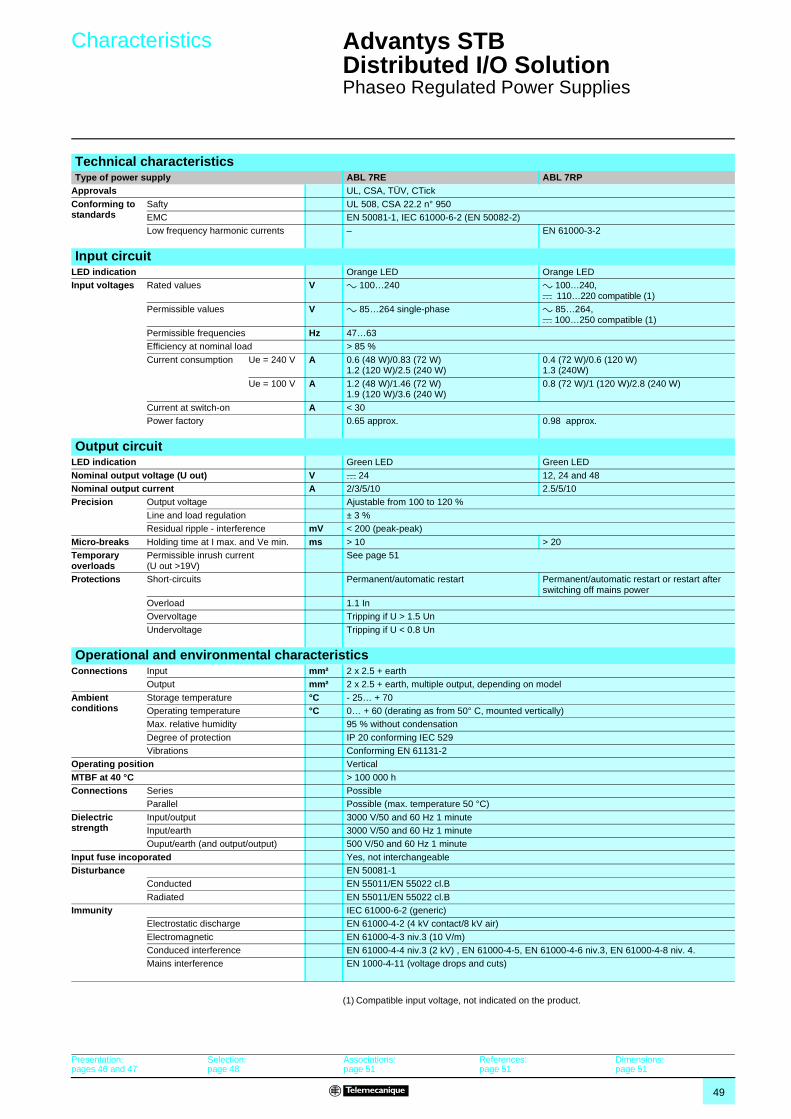
49
Characteristics Advantys STB Distributed I/O Solution 1
Phaseo Regulated Power Supplies
(1) Compatible input voltage, not indicated on the product.
Technical characteristicsType of power supply ABL 7RE ABL 7RP
Approvals UL, CSA, TÜV, CTick
Conforming to standards
Safty UL 508, CSA 22.2 n° 950EMC EN 50081-1, IEC 61000-6-2 (EN 50082-2)Low frequency harmonic currents – EN 61000-3-2
Input circuitLED indication Orange LED Orange LEDInput voltages Rated values V a 100…240 a 100…240,
c 110…220 compatible (1)Permissible values V a 85…264 single-phase a 85…264,
c 100…250 compatible (1)Permissible frequencies Hz 47…63Efficiency at nominal load > 85 %
Current consumption Ue = 240 V A 0.6 (48 W)/0.83 (72 W)1.2 (120 W)/2.5 (240 W)
0.4 (72 W)/0.6 (120 W)1.3 (240W)
Ue = 100 V A 1.2 (48 W)/1.46 (72 W)1.9 (120 W)/3.6 (240 W)
0.8 (72 W)/1 (120 W)/2.8 (240 W)
Current at switch-on A < 30Power factory 0.65 approx. 0.98 approx.
Output circuitLED indication Green LED Green LED
Nominal output voltage (U out) V c 24 12, 24 and 48Nominal output current A 2/3/5/10 2.5/5/10Precision Output voltage Ajustable from 100 to 120 %
Line and load regulation ± 3 %Residual ripple - interference mV < 200 (peak-peak)
Micro-breaks Holding time at I max. and Ve min. ms > 10 > 20Temporary overloads
Permissible inrush current (U out >19V)
See page 51
Protections Short-circuits Permanent/automatic restart Permanent/automatic restart or restart after switching off mains power
Overload 1.1 InOvervoltage Tripping if U > 1.5 Un
Undervoltage Tripping if U < 0.8 Un
Operational and environmental characteristicsConnections Input mm² 2 x 2.5 + earth
Output mm² 2 x 2.5 + earth, multiple output, depending on model
Ambient conditions
Storage temperature °C - 25… + 70Operating temperature °C 0… + 60 (derating as from 50° C, mounted vertically)Max. relative humidity 95 % without condensation
Degree of protection IP 20 conforming IEC 529Vibrations Conforming EN 61131-2
Operating position Vertical
MTBF at 40 °C > 100 000 h Connections Series Possible
Parallel Possible (max. temperature 50 °C)
Dielectric strength
Input/output 3000 V/50 and 60 Hz 1 minuteInput/earth 3000 V/50 and 60 Hz 1 minuteOuput/earth (and output/output) 500 V/50 and 60 Hz 1 minute
Input fuse incoporated Yes, not interchangeableDisturbance EN 50081-1
Conducted EN 55011/EN 55022 cl.B
Radiated EN 55011/EN 55022 cl.BImmunity IEC 61000-6-2 (generic)
Electrostatic discharge EN 61000-4-2 (4 kV contact/8 kV air)
Electromagnetic EN 61000-4-3 niv.3 (10 V/m)Conduced interference EN 61000-4-4 niv.3 (2 kV) , EN 61000-4-5, EN 61000-4-6 niv.3, EN 61000-4-8 niv. 4.Mains interference EN 1000-4-11 (voltage drops and cuts)
Presentation:pages 46 and 47
Selection:page 48
Associations:page 51
References:page 51
Dimensions:page 51
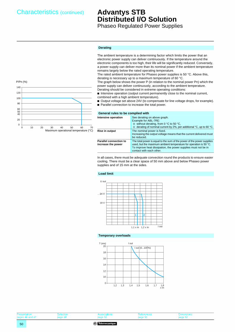
50
Characteristics (continued) Advantys STB Distributed I/O Solution 1
Phaseo Regulated Power Supplies
The ambient temperature is a determining factor which limits the power that an electronic power supply can deliver continuously. If the temperature around the electronic components is too high, their life will be significantly reduced. Conversely, a power supply can deliver more than its nominal power if the ambient temperature remains largely below the rated operating temperature.The rated ambient temperature for Phaseo power supplies is 50 °C. Above this, derating is necessary up to a maximum temperature of 60 °C.The graph below shows the power P (in relation to the nominal power Pn) which the power supply can deliver continuously, according to the ambient temperature.Derating should be considered in extreme operating conditions:b Intensive operation (output current permanently close to the nominal current, combined with a high ambient temperature).b Output voltage set above 24V (to compensate for line voltage drops, for example).b Parallel connection to increase the total power.
In all cases, there must be adequate convection round the products to ensure easier cooling. There must be a clear space of 50 mm above and below Phaseo power supplies and of 15 mm at the sides.
Derating
00 10 20 30 40 50 60 70
20
405060
80
100
120
140
P/Pn (%)
Maximum operational temperature (°C)
General rules to be complied withIntensive operation See derating on above graph.
Example for ABL-7RE:v without derating, from 0 °C to 50 °C,v derating of nominal current by 2%, per additional °C, up to 60 °C.
Rise in output The nominal power is fixed.Increasing the output voltage means that the current delivered must be reduced.
Parallel connection to increase the power
The total power is equal to the sum of the power of the power supplies used, but the maximum ambient temperature for operation is 50 °C.To improve heat dissipation, the power supplies must not be in contact with each other.
Load limit
Temporary overloads
1,2 x In1,1 x In I out
U out
19 V
1 2
1,2 1,3 1,4 1,5 1,6 1,7 1,8x In
0
10
12
14
16
18
20T (ms)
I out:(0...100%)
I out
Presentation:pages 46 and 47
Selection:page 48
Associations:page 51
References:page 51
Dimensions:page 51
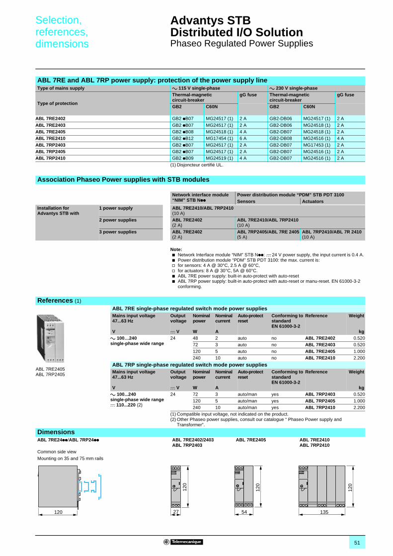
51
Selection,references,dimensions
Advantys STB Distributed I/O Solution 1
Phaseo Regulated Power Supplies
Note:b Network Interface module “NIM” STB Npp: c 24 V power supply, the input current is 0.4 A.b Power distribution module “PDM” STB PDT 3100: the max. current is:v for sensors: 4 A @ 30°C, 2.5 A @ 60°C,v for actuators: 8 A @ 30°C, 5A @ 60°C.b ABL 7RE power supply: built-in auto-protect with auto-resetb ABL 7RP power supply: built-in auto-protect with auto-reset or manu-reset. EN 61000-3-2
conforming.
ABL 7RE and ABL 7RP power supply: protection of the power supply lineType of mains supply a 115 V single-phase a 230 V single-phase
Type of protection
Thermal-magnetic circuit-breaker
gG fuse Thermal-magnetic circuit-breaker
gG fuse
GB2 C60N GB2 C60N
ABL 7RE2402 GB2 pB07 MG24517 (1) 2 A GB2-DB06 MG24517 (1) 2 A
ABL 7RE2403 GB2 pB07 MG24517 (1) 2 A GB2-DB06 MG24518 (1) 2 AABL 7RE2405 GB2 pB08 MG24518 (1) 4 A GB2-DB07 MG24518 (1) 2 AABL 7RE2410 GB2 pB12 MG17454 (1) 6 A GB2-DB08 MG24516 (1) 4 A
ABL 7RP2403 GB2 pB07 MG24517 (1) 2 A GB2-DB07 MG17453 (1) 2 AABL 7RP2405 GB2 pB07 MG24517 (1) 2 A GB2-DB07 MG24516 (1) 2 AABL 7RP2410 GB2 pB09 MG24519 (1) 4 A GB2-DB07 MG24516 (1) 2 A
(1) Disjoncteur certifié UL.
Association Phaseo Power supplies with STB modules
Network interface module “NIM” STB Npp
Power distribution module “PDM” STB PDT 3100Sensors Actuators
Installation for Advantys STB with
1 power supply ABL 7RE2410/ABL 7RP2410(10 A)
2 power supplies ABL 7RE2402 (2 A)
ABL 7RE2410/ABL 7RP2410 (10 A)
3 power supplies ABL 7RE2402(2 A)
ABL 7RP2405/ABL 7RE 2405(5 A)
ABL 7RP2410/ABL 7R 2410(10 A)
References (1)
ABL 7RE single-phase regulated switch mode power suppliesMains input voltage 47...63 Hz
V
Output voltage
c V
Nominal power
W
Nominal current
A
Auto-protect reset
Conforming to standard EN 61000-3-2
Reference Weight
kga 100…240 single-phase wide range
24 48 2 auto no ABL 7RE2402 0.52072 3 auto no ABL 7RE2403 0.520
120 5 auto no ABL 7RE2405 1.000240 10 auto no ABL 7RE2410 2.200
ABL 7RP single-phase regulated switch mode power suppliesMains input voltage 47...63 Hz
V
Output voltage
c V
Nominal power
W
Nominal current
A
Auto-protect reset
Conforming to standard EN 61000-3-2
Reference Weight
kga 100...240 single-phase wide range c 110...220 (2)
24 72 3 auto/man yes ABL 7RP2403 0.520
120 5 auto/man yes ABL 7RP2405 1.000240 10 auto/man yes ABL 7RP2410 2.200
(1) Compatible input voltage, not indicated on the product.(2) Other Phaseo power supplies, consult our catalogue “ Phaseo Power supply and
Transformer”.
DimensionsABL 7RE24pp/ABL 7RP24pp ABL 7RE2402/2403
ABL 7RP2403ABL 7RE2405 ABL 7RE2410
ABL 7RP2410Common side view
Mounting on 35 and 75 mm rails
ABL 7RE2405ABL 7RP2405
120 27
120
54 135
120
120
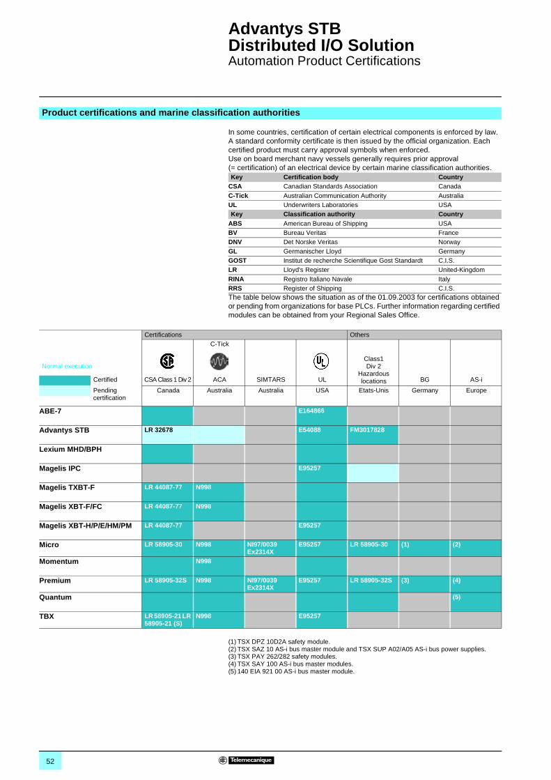
52
Advantys STB Distributed I/O Solution 1
Automation Product Certifications
In some countries, certification of certain electrical components is enforced by law. A standard conformity certificate is then issued by the official organization. Each certified product must carry approval symbols when enforced.Use on board merchant navy vessels generally requires prior approval (= certification) of an electrical device by certain marine classification authorities.
The table below shows the situation as of the 01.09.2003 for certifications obtained or pending from organizations for base PLCs. Further information regarding certified modules can be obtained from your Regional Sales Office.
(1) TSX DPZ 10D2A safety module.(2) TSX SAZ 10 AS-i bus master module and TSX SUP A02/A05 AS-i bus power supplies.(3) TSX PAY 262/282 safety modules.(4) TSX SAY 100 AS-i bus master modules.(5) 140 EIA 921 00 AS-i bus master module.
Product certifications and marine classification authorities
Key Certification body CountryCSA Canadian Standards Association Canada
C-Tick Australian Communication Authority AustraliaUL Underwriters Laboratories USAKey Classification authority Country
ABS American Bureau of Shipping USABV Bureau Veritas FranceDNV Det Norske Veritas Norway
GL Germanischer Lloyd GermanyGOST Institut de recherche Scientifique Gost Standardt C.I.S.LR Lloyd's Register United-Kingdom
RINA Registro Italiano Navale ItalyRRS Register of Shipping C.I.S.
Certifications Others
Normal execution
C-Tick
Class1 Div 2
Hazardous locationsCertified CSA Class 1 Div 2 ACA SIMTARS UL BG AS-i
Pending certification
Canada Australia Australia USA Etats-Unis Germany Europe
ABE-7 E164866
Advantys STB LR 32678 E54088 FM3017828
Lexium MHD/BPH
Magelis IPC E95257
Magelis TXBT-F LR 44087-77 N998
Magelis XBT-F/FC LR 44087-77 N998
Magelis XBT-H/P/E/HM/PM LR 44087-77 E95257
Micro LR 58905-30 N998 NI97/0039Ex2314X
E95257 LR 58905-30 (1) (2)
Momentum N998
Premium LR 58905-32S N998 NI97/0039Ex2314X
E95257 LR 58905-32S (3) (4)
Quantum (5)
TBX LR 58905-21 LR 58905-21 (S)
N998 E95257
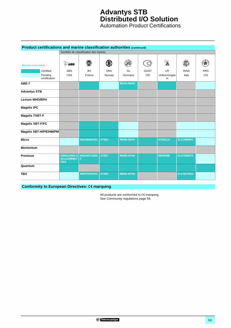
53
Advantys STB Distributed I/O Solution 1
Automation Product Certifications
All products are conformed to e marquing. See Community regulations page 55.
Product certifications and marine classification authorities (continued)
Sociétés de classification des navires
Normal execution
Certified ABS BV DNV GL GOST LR RINA RRS
Pending certification
USA France Norway Germany CEI United-Kingdom
Italy CIS
ABE-7 99155-96HH
Advantys STB
Lexium MHD/BPH
Magelis IPC
Magelis TXBT-F
Magelis XBT-F/FC
Magelis XBT-H/P/E/HM/PM
Micro 45016846A001 A7961 99086-96HH 97/00114 ELE/48896/1
Momentum
Premium 00MS14569-X00-LD186857-PDA
4501H07135/B0
A7957 99405-97HH 98/00088 ELE/35897/1
Quantum
TBX 45037058A001 A7952 99405-97HH ELE/43795/2
Conformity to European Directives: e marquing
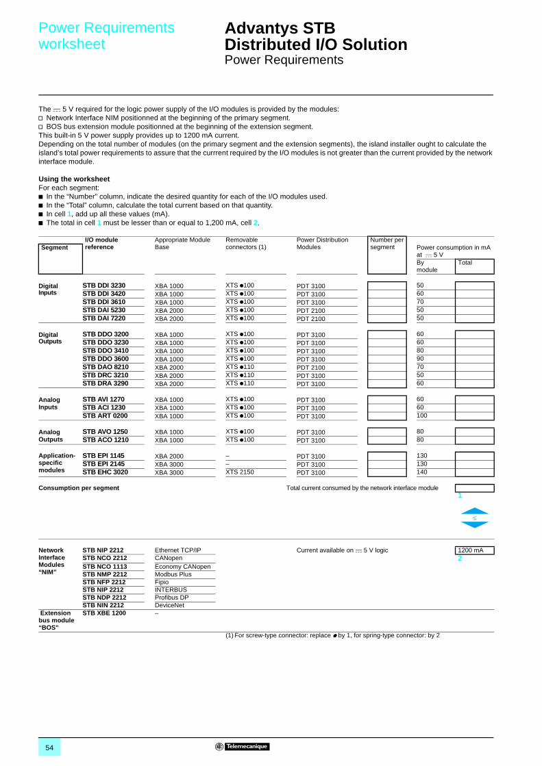
54
Power Requirements worksheet
Advantys STB Distributed I/O Solution 1
Power Requirements
The c 5 V required for the logic power supply of the I/O modules is provided by the modules: v Network Interface NIM positionned at the beginning of the primary segment.v BOS bus extension module positionned at the beginning of the extension segment.This built-in 5 V power supply provides up to 1200 mA current.Depending on the total number of modules (on the primary segment and the extension segments), the island installer ought to calculate the island’s total power requirements to assure that the currrent required by the I/O modules is not greater than the current provided by the network interface module.
Using the worksheet For each segment:b In the “Number” column, indicate the desired quantity for each of the I/O modules used.b In the “Total” column, calculate the total current based on that quantity.b In cell 1, add up all these values (mA).b The total in cell 1 must be lesser than or equal to 1,200 mA, cell 2.
I/O module reference
Appropriate Module Base
Removable connectors (1)
Power Distribution Modules
Number per segmentSegment Power consumption in mA
at c 5 VBymodule
Total
DigitalInputs
STB DDI 3230 XBA 1000 XTS p100 PDT 3100 50STB DDI 3420 XBA 1000 XTS p100 PDT 3100 60STB DDI 3610 XBA 1000 XTS p100 PDT 3100 70STB DAI 5230 XBA 2000 XTS p100 PDT 2100 50STB DAI 7220 XBA 2000 XTS p100 PDT 2100 50
Digital Outputs
STB DDO 3200 XBA 1000 XTS p100 PDT 3100 60STB DDO 3230 XBA 1000 XTS p100 PDT 3100 60STB DDO 3410 XBA 1000 XTS p100 PDT 3100 80STB DDO 3600 XBA 1000 XTS p100 PDT 3100 90STB DAO 8210 XBA 2000 XTS p110 PDT 2100 70STB DRC 3210 XBA 2000 XTS p110 PDT 3100 50STB DRA 3290 XBA 2000 XTS p110 PDT 3100 60
Analog Inputs
STB AVI 1270 XBA 1000 XTS p100 PDT 3100 60STB ACI 1230 XBA 1000 XTS p100 PDT 3100 60STB ART 0200 XBA 1000 XTS p100 PDT 3100 100
Analog Outputs
STB AVO 1250 XBA 1000 XTS p100 PDT 3100 80STB ACO 1210 XBA 1000 XTS p100 PDT 3100 80
Application-specific modules
STB EPI 1145 XBA 2000 – PDT 3100 130STB EPI 2145 XBA 3000 – PDT 3100 130STB EHC 3020 XBA 3000 XTS 2150 PDT 3100 140
Consumption per segment Total current consumed by the network interface module 1
Network Interface Modules “NIM”
STB NIP 2212 Ethernet TCP/IP Current available on c 5 V logic 1200 mASTB NCO 2212 CANopen 2 STB NCO 1113 Economy CANopenSTB NMP 2212 Modbus PlusSTB NFP 2212 FipioSTB NIP 2212 INTERBUSSTB NDP 2212 Profibus DPSTB NIN 2212 DeviceNet
Extension bus module “BOS”
STB XBE 1200 –
(1) For screw-type connector: replace p by 1, for spring-type connector: by 2
55
Advantys STB Distributed I/O Solution 1
Community Regulations and Protective Treatment
The opening of European markets implies a harmonization of regulations in the various European Union member states.European Directives are documents used to remove obstacles to the free movement of goods and their application is compulsory in all states of the European Union.Member states are obliged to transcribe each Directive into their national legislation and, at the same time, to withdraw any conflicting regulations.The Directives, particularly those of a technical nature with which we are concerned, only set objectives, called “general requirements”.The manufacturer must take all necessary measures to ensure that his products conform to the requirements of each Directive relating to his equipment.As a general rule, the manufacturer affirms that his product conforms to the necessary requirements of the Directive(s) by applying the e label to his product.e marking is applied to Telemecanique products where relevant.
p e marking on a product means that the manufacturer certifies that his product conforms to the relevant European Directives ; it is necessary in order that a product which is subject to a Directive(s) can be marketed and freely moved within the European Union.p e marking is intended solely for the national authorities responsible for market regulation.
For electrical equipment, only conformity of the product to standards indicates that it is suitable for use, and only a guarantee by a recognised manufacturer can ensure a high level of quality.One or more Directives, as appropriate, may apply to our products, in particular :p The Low Voltage Directive 72/23/EEC amended by Directive 93/68/EEC : e marking under the terms of this Directive could not be applied before 1 January 1995 and is compulsory as of 1 January 1997.p The Electromagnetic Compatibility Directive 89/336/EEC, amended by Directives 92/31/EEC and 93/68/EEC : e marking on the products covered by this Directive has been compulsory since 1 January 1996.
Advantys, STB distributed I/O meet the requirements of “TC” treatment (1).For installations in industrial production workshops or in an environment which corresponds to “TH” treatment (2), STB distributed I/O should be enclosed in casings with a minimum of IP 54 protection as prescribed by standards IEC.Advantys, STB distributed I/O are supplied with an IP 20 protection index. They can therefore be installed without enclosure in locations with restricted access which do not exceed pollution degree 2 (control room which does not contain a machine or dust-producing activity).
(1) “TC” treatment : all climate treatment.(2) “TH” treatment : treatment for hot and humid environments.
Community regulationsEuropean Directives
The significance of e marking
Protective treatment of equipment
© Copyright Schneider Electric SAS 2003.All rights reserved. No part of this work may be translated and/or reproduced or copied in any form or by any means - graphic, electronic or mechanical including photocopying, recording, taping or storage in an information retrieval system.
All products, hardware, software and services shown in this document are subject to modification and change without notice. Any descriptions or specifications given herein shall not be capable as being interpreted as part or a condition of any contract relative to such product, software or service.
All software quoted in this document is the property of Schneider Automation, or a third party which has granted rights to Schneider Automation. The supply of such software confers a non-exclusive licence on the recipient to use such software solely for the purpose for which it was supplied.Any copying of such software, etc. (except solely for the purpose of producing back-up and security copies) is totally forbidden.
Advantys, Modbus Plus, Fipio, PL7, Unity are registered trademarks of Schneider Automation.Telemecanique, Phaseo, Tego, TeSys are registered trademarks of Schneider Electric SAS.All other products and brands quoted in this document are registered trademarks of their respective holders.
56
Product Reference Index
1170 BNO 671 00 13170 MCI 007 00 13170 MCI 020 10 12170 MCI 020 36 12170 MCI 020 80 12170 MCI 021 20 12170 MCI 100 00 13170 XTS 020 00 12
4490 NAD 911 03 13490 NAD 911 04 13490 NAD 911 05 13490 NTW 000 02 12 and
37490 NTW 000 05 12 and
37490 NTW 000 12 37490 NTW 000 40 12490 NTW 000 80 12490 NTW 00012 12
9990 NAD 211 10 12990 NAD 211 30 12990 NAD 230 00 12990 NAD 230 10 12
AABL 7RE2402 51ABL 7RE2403 51ABL 7RE2405 51ABL 7RE2410 51ABL 7RP2403 51ABL 7RP2405 51ABL 7RP2410 51APP 2R2E 35APP 2R4E 35AS MBKT 085 12
LLU9 R03 37LU9 R10 37LU9 R30 37
SSTB ACI 1230 31STB ACO 1210 31STB ART 0200 31STB AVI 1270 31STB AVO 1250 31STB DAI 5230 22STB DAI 7220 22STB DAO 8210 22STB DDI 3230 22STB DDI 3420 22STB DDI 3610 22STB DDO 3200 22STB DDO 3230 22STB DDO 3410 22STB DDO 3600 22STB DRA 3290 22STB DRC 3210 22STB EHC 3020 41STB EPI 1145 35STB EPI 2145 37STB NCO 1113 11STB NCO 2212 11STB NDN 2212 11STB NDP 2212 11STB NFP 2212 11STB NIB 2212 11STB NIP 2212 11STB NMP 2212 11STB PDT 2100 15STB PDT 3100 15STB SPU 1000 45STB SUS 8800 45STB XBA 1000 22 and
31STB XBA 2000 5, 22
and 35STB XBA 2200 15STB XBA 2300 5STB XBA 2400 5STB XBA 3000 22, 37
and 41STB XBE 1000 5STB XBE 1200 5STB XBE 2100 5STB XCA 1001 5STB XCA 1002 5STB XCA 1003 5STB XCA 1004 5STB XCA 1006 5STB XCA 3002 35STB XCA 3003 35STB XCA 4002 11STB XMP 1100 11STB XMP 4440 11STB XMP 5600 15STB XMP 6700 5, 15, 22,
31, 35,37
and 41STB XMP 7700 15, 22,
31, 35,37
and 41STB XMP 7800 22, 31
and 41STB XMP 7810 15STB XSP 3000 15STB XSP 3010 15STB XSP 3020 15
STB XTS 1100 22 and31
STB XTS 1110 5 and 22STB XTS 1111 11 and
13STB XTS 1120 5, 11 and
22STB XTS 1130 15STB XTS 2100 22 and
31STB XTS 2110 5 and 22STB XTS 2111 11 and
13STB XTS 2120 5 and 11STB XTS 2130 15STB XTS 2150 41
TTSX CPP ACC 1 12TSX FP ACC 12 12TSX FP ACC 14 12TSX FP ACC 2 12TSX FP ACC 4 12TSX FP CC 100 12TSX FP CC 200 12TSX FP CC 500 12TSX IBS CA 100 13TSX IBS CA 400 13TSX PBS CA 100 13TSX PBS CA 400 13

09-0
3 Distributed I/OAdvantys STBThe open device integration I/O system
Catalogue September
Dis
trib
uted
I/O
Adv
anty
s S
TB
www.schneider-electric.com
September 2003
Schneider Electric Industries SAS
DIA
6ED
2030
901E
N -
© 2
003
Sch
neid
er E
lect
ric -
All
right
s re
serv
ed
ART. 061231
Tel
emec
aniq
ue