Embed Size (px)
Citation preview
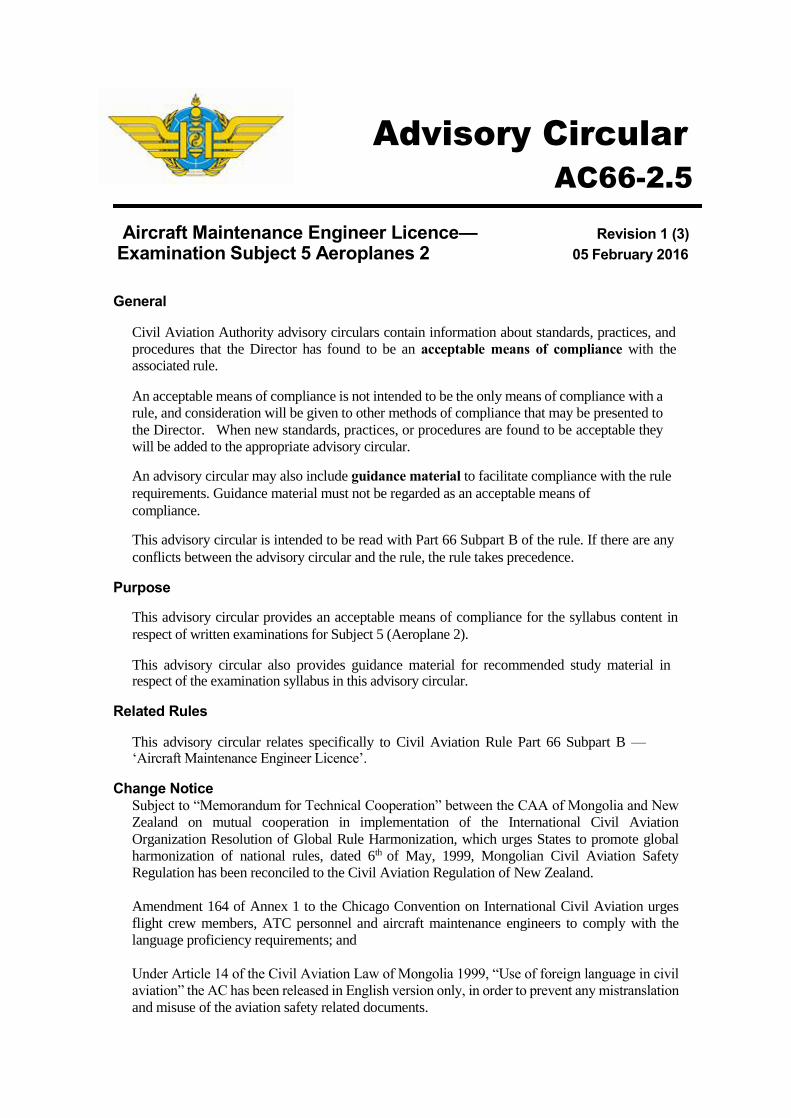
Advisory Circular
AC66-2.5
Aircraft Maintenance Engineer Licence— Revision 1 (3)
Examination Subject 5 Aeroplanes 2 05 February 2016
General
Civil Aviation Authority advisory circulars contain information about standards, practices, and
procedures that the Director has found to be an acceptable means of compliance with the associated rule.
An acceptable means of compliance is not intended to be the only means of compliance with a
rule, and consideration will be given to other methods of compliance that may be presented to
the Director. When new standards, practices, or procedures are found to be acceptable they
will be added to the appropriate advisory circular.
An advisory circular may also include guidance material to facilitate compliance with the rule
requirements. Guidance material must not be regarded as an acceptable means of
compliance.
This advisory circular is intended to be read with Part 66 Subpart B of the rule. If there are any
conflicts between the advisory circular and the rule, the rule takes precedence.
Purpose
This advisory circular provides an acceptable means of compliance for the syllabus content in
respect of written examinations for Subject 5 (Aeroplane 2).
This advisory circular also provides guidance material for recommended study material in respect of the examination syllabus in this advisory circular.
Related Rules
This advisory circular relates specifically to Civil Aviation Rule Part 66 Subpart B — ‘Aircraft Maintenance Engineer Licence’.
Change Notice Subject to “Memorandum for Technical Cooperation” between the CAA of Mongolia and New
Zealand on mutual cooperation in implementation of the International Civil Aviation
Organization Resolution of Global Rule Harmonization, which urges States to promote global
harmonization of national rules, dated 6th of May, 1999, Mongolian Civil Aviation Safety
Regulation has been reconciled to the Civil Aviation Regulation of New Zealand.
Amendment 164 of Annex 1 to the Chicago Convention on International Civil Aviation urges
flight crew members, ATC personnel and aircraft maintenance engineers to comply with the
language proficiency requirements; and
Under Article 14 of the Civil Aviation Law of Mongolia 1999, “Use of foreign language in civil
aviation” the AC has been released in English version only, in order to prevent any mistranslation
and misuse of the aviation safety related documents.
Advisory Circular AC66-2.5 Revision 1
Table of Contents Rule 66.53 Eligibility Requirements ... ....................................................................... 5
Examination Overview: Subject 5 ... .................................................................... ... 6 General Examining Objective ... ............................................................................................ . 6 Knowledge Levels ... ........................................................................................................... ... 6
Recommended Study Material ... ................................................................................ 7
Syllabus Layout ... .................................................................................................... ... 8
Syllabus: Subject 5 (Aeroplanes 2) ... ..................................................................... .. 9
1 Theory of Flight ... ................................................................................................ .. 9 High Speed flight ... ........................................................................................................... ... 9 Shock Waves ... ................................................................................................................. ... 9 Speed of Sound ... .............................................................................................................. .. 9
Sweepback ... .................................................................................................................... .. 10 Control of High Speed Aircraft ... .................................................................................. ... 10
Boundary Layer Control ... ............................................................................................... . 10 Aerodynamic Balancing ... .............................................................................................. .. 10
Lift and Drag Devices on High Speed Aircraft ... .......................................................... .. 10 Low Speed Performance ... .............................................................................................. . 11
2 Structure of Jet and Turbo-prop Aircraft ... ....................................................... 12 ATA-100 Identification System ... .................................................................................. ... 12 Pressurised Structure Fundamentals - Fuselage ... ..................................................... .. 12 Fuselage Sealing ... ........................................................................................................... . 12 Fuselage Design Concepts, Equipment, Furnishings and Lights ... ........................... . 13 Wings ... ............................................................................................................................. . 13 Stabilisers ... .................................................................................................................... ... 14 Nacelles and Pylons ... .................................................................................................... .. 14 Flight Control Surfaces .................................................................................................. ... 14 Doors ... ............................................................................................................................. . 14 Glass Windows and Windscreens ... ............................................................................. ... 14
3 Control Systems ... ................................................................................................ 15 Flight Controls ... .............................................................................................................. .. 15 Flight Control System Components ... .......................................................................... ... 15 Flutter ... ............................................................................................................................. . 15 Automatic Flight Control Systems ... ............................................................................ ... 15 Fly-By-Wire Systems ... .................................................................................................... . 16
4 Hydraulic Systems ... ............................................................................................ 17 Hydraulic System Layout ... ........................................................................................... ... 17 Hydraulic Fluids ... ........................................................................................................... .. 17 Hydraulic Filters ... ........................................................................................................... .. 17 Pressurised Reservoirs ... ............................................................................................... .. 18 Hydraulic Pumps ... ........................................................................................................... . 18 Hydraulic System Flow Control Valves ... ...................................................................... . 18
Hydraulic System Pressure Control Devices ... ............................................................. . 18 Actuating Cylinders and Hydraulic Motors ... ................................................................ . 19
Hydraulic Seals ... .............................................................................................................. . 19 Hydraulic Indicating Systems ... ...................................................................................... . 19
Emergency Hydraulic Systems ... .................................................................................. .. 19
5 Landing Gear ... ..................................................................................................... 20 Landing Gear System Configuration ... ......................................................................... .. 20 Landing Gear System Components ... ............................................................................ . 20 Shock Struts ... ................................................................................................................. .. 20 Landing Gear Rigging ... .................................................................................................. .. 21
Nose Wheel Steering Systems ... .................................................................................. ... 21
05.Feb.2016 2 CAA of Mongolia
Advisory Circular AC66-2.5 Revision 1
Nose Wheel Shimmy Damping ... .................................................................................. ... 21 Retraction Systems ... ..................................................................................................... ... 21
Wheel Assemblies ... ........................................................................................................ .. 22 Inspection of Wheel Assemblies ... ............................................................................... ... 22
Tyre Assemblies ... ........................................................................................................... .. 22 Maintenance of Tyres ... ................................................................................................. ... 23
Operating Characteristics of Tyres ... ............................................................................ .. 23 Tyre Pressure Loss ... ..................................................................................................... ... 24
Assessment of Tyre Condition and Defects ... .............................................................. .. 24 Brake Assemblies ... ........................................................................................................ .. 24
Brake System Operation ... .............................................................................................. . 25 Brake Defects ... .............................................................................................................. ... 25 Monitoring of Brake Temperature ... ............................................................................... . 25 Anti-skid Brake Control System ... .................................................................................. . 25
6 Pneumatic Systems ... .......................................................................................... 26 Pneumatic System Layout ... ........................................................................................... . 26
7 Pressurisation Systems ... ................................................................................... 27 Terminology ... ................................................................................................................. ... 27 Basic System Requirements ... ...................................................................................... ... 27 Pressurisation System Components ... ......................................................................... .. 27 System Layout ... .............................................................................................................. .. 27 Cabin Air Distribution ... .................................................................................................. .. 28 System Operation ... ....................................................................................................... ... 28 Fault Finding and Maintenance ... .................................................................................. .. 28
8 Air-conditioning Systems ... ................................................................................ 29 General Functions ... ........................................................................................................ .. 29 Air-Conditioning Principles and Terminology ... .......................................................... .. 29 Vapour Cycle System ... ................................................................................................. ... 29 Air-Cycle System Components ... .................................................................................. .. 30 Basic Air-Cycle System Layout and Operation ... ........................................................ ... 30 Typical Aircraft Air-Cycle System Layout, Operation and Fault Finding ... .............. .. 30 Temperature Control and Air Distribution ... ................................................................ ... 30
9 Oxygen Systems ... ............................................................................................... 32 General ... .......................................................................................................................... .. 32
Forms of Oxygen ... ........................................................................................................... . 32 Continuous Flow and Pressure Demand Systems ... .................................................... . 32 Chemical Oxygen Systems ... ........................................................................................ ... 33 Portable Oxygen Equipment ... ...................................................................................... ... 33 System Advantages ... ..................................................................................................... .. 33 Oxygen System Servicing and Precautions ... ............................................................. ... 33
10 Ice and Rain Protection Systems ... .................................................................... 34 General ... .......................................................................................................................... .. 34 Ice Detecting Devices ... ................................................................................................. ... 34 Pneumatic De Ice System ... ............................................................................................ .. 34
Pneumatic De-Ice System Maintenance ... ................................................................... ... 34 Thermal Anti-Ice Systems ... ........................................................................................... .. 35
Chemical (Fluid) De-icing systems ... ............................................................................. .. 35 Rain Control Systems ... .................................................................................................. .. 35
11 Fuel Systems ... ..................................................................................................... 36 General ... .......................................................................................................................... .. 36 Fuel System Maintenance ... ........................................................................................... .. 36 Fuel Contents and Flow Measurement ... ...................................................................... .. 36
12 Fire Detection and Extinguishing Systems ... .................................................... 38 General ... .......................................................................................................................... .. 38 Fixed Fire Extinguishing Systems ................................................................................ ... 38
Portable Fire Extinguishing Systems ............................................................................. . 38 Inspection and Maintenance ... ...................................................................................... ... 38 Extinguisher Agents ... .................................................................................................... .. 38 Smoke Detection ... ........................................................................................................... . 38 Master Central Warning Systems ... ................................................................................ . 39
13 Reliability Fundamentals and Aircraft Structural Maintenance
Concepts ... ......................................................................................................... .. 40 05.Feb.2016 3 CAA of Mongolia
Advisory Circular AC66-2.5 Revision 1
Terminology ... ....................................................................................................................... ... 40 Failure ... .................................................................................................................................... . 40
Maintenance Programmes ... ................................................................................................. . 40 Quality Fundamentals ... .......................................................................................................... 41
Service Data ... ....................................................................................................................... ... 41
05.Feb.2016 4 CAA of Mongolia
Advisory Circular AC66-2.5 Revision 1
Rule 66.53 Eligibility Requirements
Rule 66.53(a)(2) requires an applicant for an AMEL to have passed written examinations, that are
acceptable to the Director, relevant to the duties and responsibilities of an aircraft maintenance engineer in the category of licence sought.
The written examinations acceptable to the Director for Subject 5 (Aeroplanes 2) should comply with
the syllabus contained in this advisory circular. Each examination will cover all topics and may sample any of the sub-topics.
The new syllabus has been developed after extensive industry consultation and the objectives reflect the knowledge required of current technology and international best work practice.
05.Feb.2016 5 CAA of Mongolia
Advisory Circular AC66-2.5 Revision 1
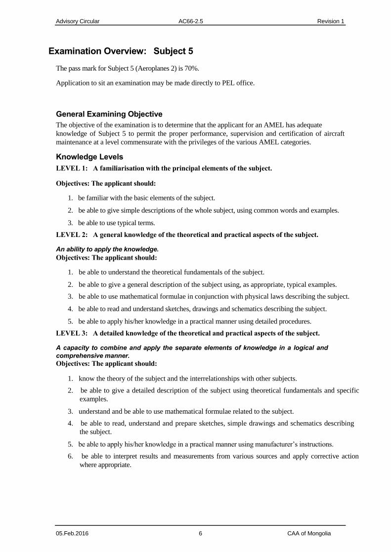
Examination Overview: Subject 5
The pass mark for Subject 5 (Aeroplanes 2) is 70%.
Application to sit an examination may be made directly to PEL office.
General Examining Objective
The objective of the examination is to determine that the applicant for an AMEL has adequate
knowledge of Subject 5 to permit the proper performance, supervision and certification of aircraft
maintenance at a level commensurate with the privileges of the various AMEL categories.
Knowledge Levels
LEVEL 1: A familiarisation with the principal elements of the subject.
Objectives: The applicant should:
1. be familiar with the basic elements of the subject.
2. be able to give simple descriptions of the whole subject, using common words and examples.
3. be able to use typical terms.
LEVEL 2: A general knowledge of the theoretical and practical aspects of the subject.
An ability to apply the knowledge.
Objectives: The applicant should:
1. be able to understand the theoretical fundamentals of the subject.
2. be able to give a general description of the subject using, as appropriate, typical examples.
3. be able to use mathematical formulae in conjunction with physical laws describing the subject.
4. be able to read and understand sketches, drawings and schematics describing the subject.
5. be able to apply his/her knowledge in a practical manner using detailed procedures.
LEVEL 3: A detailed knowledge of the theoretical and practical aspects of the subject.
A capacity to combine and apply the separate elements of knowledge in a logical and
comprehensive manner.
Objectives: The applicant should:
1. know the theory of the subject and the interrelationships with other subjects.
2. be able to give a detailed description of the subject using theoretical fundamentals and specific
examples.
3. understand and be able to use mathematical formulae related to the subject.
4. be able to read, understand and prepare sketches, simple drawings and schematics describing
the subject.
5. be able to apply his/her knowledge in a practical manner using manufacturer’s instructions.
6. be able to interpret results and measurements from various sources and apply corrective action
where appropriate. 05.Feb.2016 6 CAA of Mongolia
Advisory Circular AC66-2.5 Revision 1
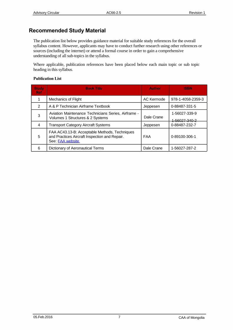
Recommended Study Material
The publication list below provides guidance material for suitable study references for the overall
syllabus content. However, applicants may have to conduct further research using other references or
sources (including the internet) or attend a formal course in order to gain a comprehensive
understanding of all sub-topics in the syllabus.
Where applicable, publication references have been placed below each main topic or sub topic
heading in this syllabus.
Publication List
Study Book Title Author ISBN Ref
1 Mechanics of Flight AC Kermode 978-1-4058-2359-3
2 A & P Technician Airframe Textbook Jeppesen 0-88487-331-5
3 Aviation Maintenance Technicians Series, Airframe - Volumes 1 Structures & 2 Systems
1-56027-339-9 Dale Crane
1-56027-340-2 4 Transport Category Aircraft Systems Jeppesen 0-88487-232-7
FAA AC43.13-B: Acceptable Methods, Techniques 5 and Practices Aircraft Inspection and Repair. FAA 0-89100-306-1
See: FAA website
6 Dictionary of Aeronautical Terms Dale Crane 1-56027-287-2
05.Feb.2016 7 CAA of Mongolia
Advisory Circular AC66-2.5 Revision 1
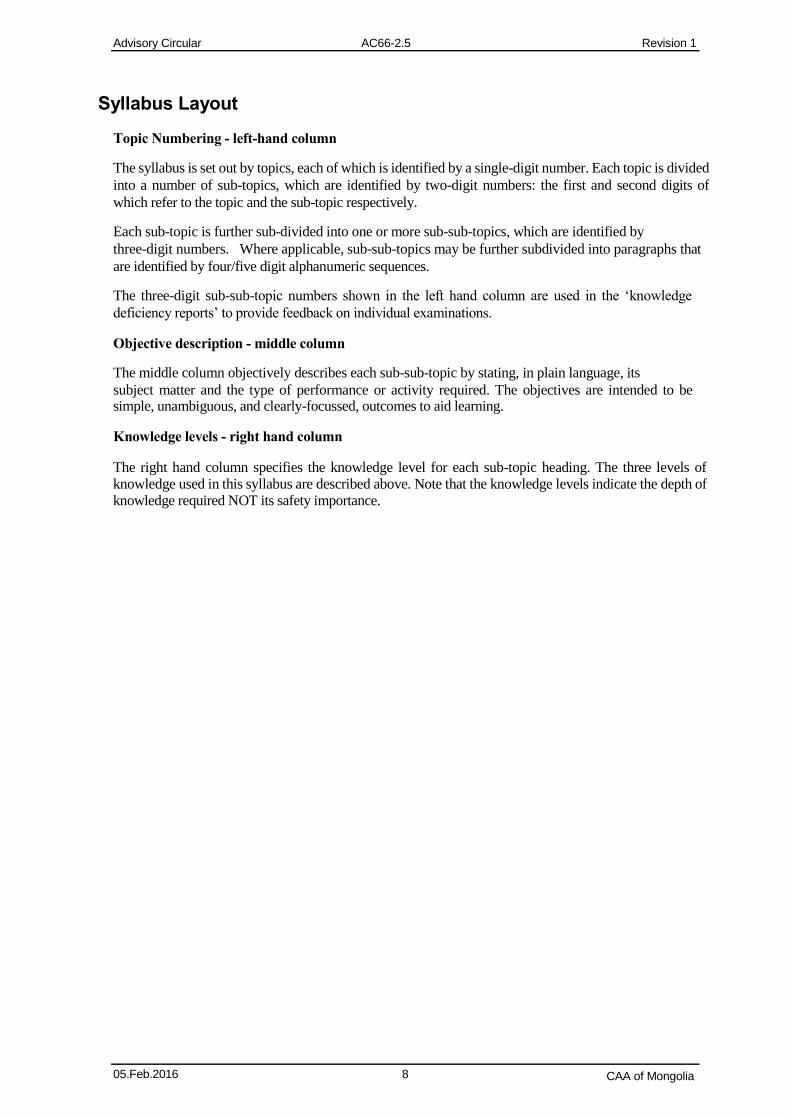
Syllabus Layout
Topic Numbering - left-hand column
The syllabus is set out by topics, each of which is identified by a single-digit number. Each topic is divided
into a number of sub-topics, which are identified by two-digit numbers: the first and second digits of
which refer to the topic and the sub-topic respectively.
Each sub-topic is further sub-divided into one or more sub-sub-topics, which are identified by
three-digit numbers. Where applicable, sub-sub-topics may be further subdivided into paragraphs that
are identified by four/five digit alphanumeric sequences.
The three-digit sub-sub-topic numbers shown in the left hand column are used in the ‘knowledge
deficiency reports’ to provide feedback on individual examinations.
Objective description - middle column
The middle column objectively describes each sub-sub-topic by stating, in plain language, its
subject matter and the type of performance or activity required. The objectives are intended to be simple, unambiguous, and clearly-focussed, outcomes to aid learning.
Knowledge levels - right hand column
The right hand column specifies the knowledge level for each sub-topic heading. The three levels of knowledge used in this syllabus are described above. Note that the knowledge levels indicate the depth of knowledge required NOT its safety importance.
05.Feb.2016 8 CAA of Mongolia
Advisory Circular AC66-2.5 Revision 1
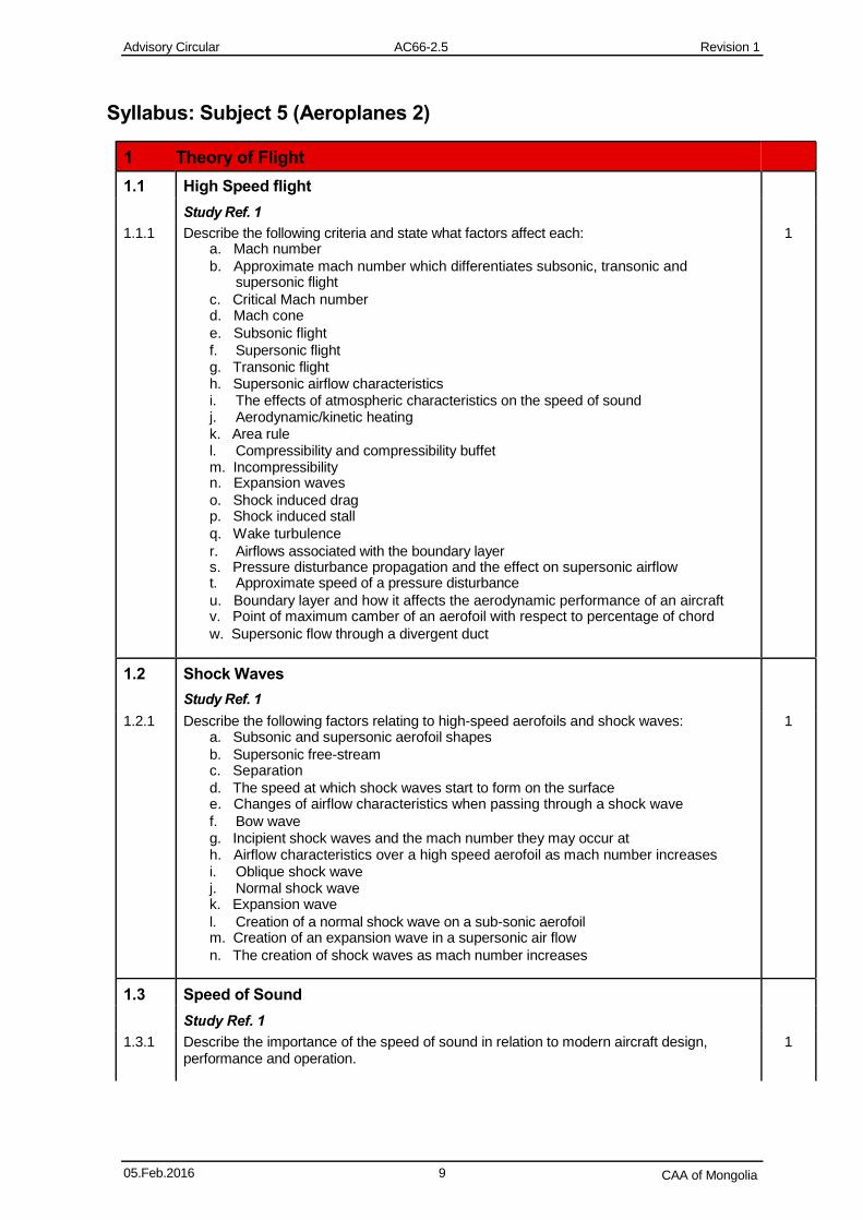
Syllabus: Subject 5 (Aeroplanes 2)
1 Theory of Flight
1.1 High Speed flight
Study Ref. 1
1.1.1 Describe the following criteria and state what factors affect each: 1 a. Mach number
b. Approximate mach number which differentiates subsonic, transonic and supersonic flight
c. Critical Mach number d. Mach cone
e. Subsonic flight
f. Supersonic flight g. Transonic flight h. Supersonic airflow characteristics i. The effects of atmospheric characteristics on the speed of sound j. Aerodynamic/kinetic heating k. Area rule l. Compressibility and compressibility buffet m. Incompressibility n. Expansion waves
o. Shock induced drag p. Shock induced stall
q. Wake turbulence
r. Airflows associated with the boundary layer s. Pressure disturbance propagation and the effect on supersonic airflow t. Approximate speed of a pressure disturbance
u. Boundary layer and how it affects the aerodynamic performance of an aircraft v. Point of maximum camber of an aerofoil with respect to percentage of chord
w. Supersonic flow through a divergent duct
1.2 Shock Waves
Study Ref. 1
1.2.1 Describe the following factors relating to high-speed aerofoils and shock waves: 1 a. Subsonic and supersonic aerofoil shapes
b. Supersonic free-stream c. Separation
d. The speed at which shock waves start to form on the surface e. Changes of airflow characteristics when passing through a shock wave
f. Bow wave g. Incipient shock waves and the mach number they may occur at h. Airflow characteristics over a high speed aerofoil as mach number increases i. Oblique shock wave j. Normal shock wave k. Expansion wave
l. Creation of a normal shock wave on a sub-sonic aerofoil m. Creation of an expansion wave in a supersonic air flow
n. The creation of shock waves as mach number increases
1.3 Speed of Sound
Study Ref. 1
1.3.1 Describe the importance of the speed of sound in relation to modern aircraft design, 1 performance and operation.
05.Feb.2016 9 CAA of Mongolia
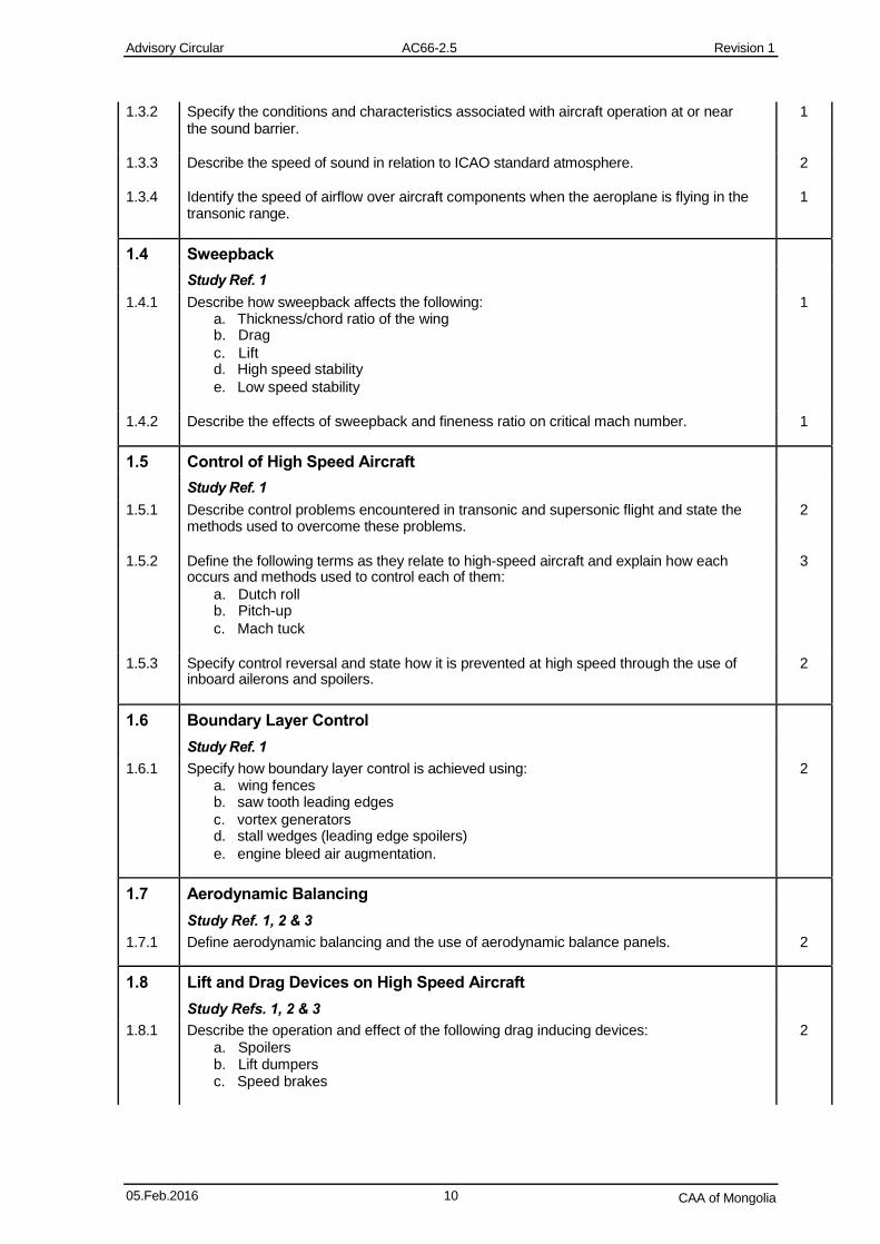
Advisory Circular AC66-2.5 Revision 1
1.3.2 Specify the conditions and characteristics associated with aircraft operation at or near 1 the sound barrier.
1.3.3 Describe the speed of sound in relation to ICAO standard atmosphere. 2
1.3.4 Identify the speed of airflow over aircraft components when the aeroplane is flying in the 1 transonic range.
1.4 Sweepback
Study Ref. 1
1.4.1 Describe how sweepback affects the following: 1 a. Thickness/chord ratio of the wing b. Drag
c. Lift d. High speed stability
e. Low speed stability
1.4.2 Describe the effects of sweepback and fineness ratio on critical mach number. 1
1.5 Control of High Speed Aircraft
Study Ref. 1
1.5.1 Describe control problems encountered in transonic and supersonic flight and state the 2 methods used to overcome these problems.
1.5.2 Define the following terms as they relate to high-speed aircraft and explain how each 3 occurs and methods used to control each of them:
a. Dutch roll b. Pitch-up
c. Mach tuck
1.5.3 Specify control reversal and state how it is prevented at high speed through the use of 2 inboard ailerons and spoilers.
1.6 Boundary Layer Control
Study Ref. 1
1.6.1 Specify how boundary layer control is achieved using: 2 a. wing fences b. saw tooth leading edges
c. vortex generators d. stall wedges (leading edge spoilers)
e. engine bleed air augmentation.
1.7 Aerodynamic Balancing
Study Ref. 1, 2 & 3
1.7.1 Define aerodynamic balancing and the use of aerodynamic balance panels. 2
1.8 Lift and Drag Devices on High Speed Aircraft
Study Refs. 1, 2 & 3
1.8.1 Describe the operation and effect of the following drag inducing devices: 2 a. Spoilers b. Lift dumpers c. Speed brakes
05.Feb.2016 10 CAA of Mongolia
Advisory Circular AC66-2.5 Revision 1
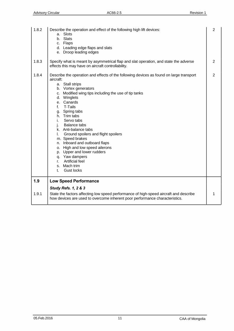
1.8.2 Describe the operation and effect of the following high lift devices: 2 a. Slots
b. Slats c. Flaps
d. Leading edge flaps and slats e. Droop leading edges
1.8.3 Specify what is meant by asymmetrical flap and slat operation, and state the adverse 2 effects this may have on aircraft controllability.
1.8.4 Describe the operation and effects of the following devices as found on large transport 2 aircraft:
a. Stall strips b. Vortex generators
c. Modified wing tips including the use of tip tanks d. Winglets
e. Canards
f. T-Tails g. Spring tabs h. Trim tabs i. Servo tabs j. Balance tabs k. Anti-balance tabs l. Ground spoilers and flight spoilers m. Speed brakes n. Inboard and outboard flaps
o. High and low speed ailerons p. Upper and lower rudders
q. Yaw dampers r. Artificial feel s. Mach trim t. Gust locks
1.9 Low Speed Performance
Study Refs. 1, 2 & 3
1.9.1 State the factors affecting low speed performance of high-speed aircraft and describe 1 how devices are used to overcome inherent poor performance characteristics.
05.Feb.2016 11 CAA of Mongolia
Advisory Circular AC66-2.5 Revision 1
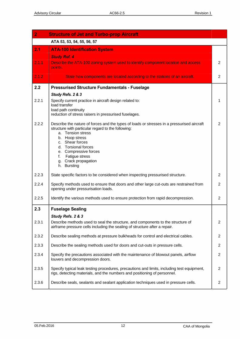
2 Structure of Jet and Turbo-prop Aircraft
ATA 53, 53, 54, 55, 56, 57
2.1 ATA-100 Identification System
Study Ref. 4
2.1.1 Describe the ATA-100 zoning system used to identify component location and access 2 points.
2.1.2 State how components are located according to the stations of an aircraft. 2
2.2 Pressurised Structure Fundamentals - Fuselage
Study Refs. 2 & 3
2.2.1 Specify current practice in aircraft design related to: 1 load transfer
load path continuity reduction of stress raisers in pressurised fuselages.
2.2.2 Describe the nature of forces and the types of loads or stresses in a pressurised aircraft 2 structure with particular regard to the following:
a. Tension stress
b. Hoop stress c. Shear forces
d. Torsional forces e. Compressive forces
f. Fatigue stress g. Crack propagation h. Bursting
2.2.3 State specific factors to be considered when inspecting pressurised structure. 2
2.2.4 Specify methods used to ensure that doors and other large cut-outs are restrained from 2 opening under pressurisation loads.
2.2.5 Identify the various methods used to ensure protection from rapid decompression. 2
2.3 Fuselage Sealing
Study Refs. 2 & 3
2.3.1 Describe methods used to seal the structure, and components to the structure of 2 airframe pressure cells including the sealing of structure after a repair.
2.3.2 Describe sealing methods at pressure bulkheads for control and electrical cables. 2
2.3.3 Describe the sealing methods used for doors and cut-outs in pressure cells. 2
2.3.4 Specify the precautions associated with the maintenance of blowout panels, airflow 2 louvers and decompression doors.
2.3.5 Specify typical leak testing procedures, precautions and limits, including test equipment, 2 rigs, detecting materials, and the numbers and positioning of personnel.
2.3.6 Describe seals, sealants and sealant application techniques used in pressure cells. 2
05.Feb.2016 12 CAA of Mongolia
Advisory Circular AC66-2.5 Revision 1
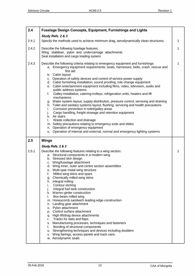
2.4 Fuselage Design Concepts, Equipment, Furnishings and Lights
Study Refs. 2 & 3
2.4.1 Specify the methods used to achieve minimum drag, aerodynamically clean structures. 1 2.4.2 Describe the following fuselage features. 1
Wing, stabiliser, pylon and undercarriage attachments
Seat installation and cargo loading system
2.4.3 Describe the following criteria relating to emergency equipment and furnishings: 1 a. Emergency equipment requirements; seats, harnesses, belts, crash, rescue and
first aid b. Cabin layout
c. Operation of safety devices and control of service power supply d. Cabin furnishing installation, sound proofing, role change equipment
e. Cabin entertainment equipment including films, video, television, audio and public address systems
f. Galley installation, catering trolleys, refrigeration units, heaters and lift mechanisms
g. Water system layout, supply distribution, pressure control, servicing and draining h. Toilet and sanitary systems layout, flushing, servicing and health precautions i. Corrosion prevention in toilet/galley areas j. Cargo handling, freight stowage and retention equipment k. Air stairs l. Waste collection and drainage
m. Safety precautions relating to emergency exits and slides n. Operation of emergency equipment
o. Operation of internal and external, normal and emergency lighting systems
2.5 Wings
Study Refs. 2 & 3
2.5.1 Describe the following features relating to a wing section: 1 a. Structural components in a modern wing b. Stressed skin design
c. Wing/fuselage attachment d. Wing inner, outer and centre section assemblies
e. Multi-spar metal wing structure f. Milled wing skins and spars g. Chemically milled wing skins h. Integral milling i. Contour etching j. Integral fuel tank construction k. Warren girder construction l. Box-beam milled wing m. Honeycomb sandwich leading edge construction n. Landing gear attachment
o. Pylon attachment p. Control surface attachment
q. High lift/drag device attachments r. Tracks for slats and flaps
s. Manufacturing processes, techniques and fasteners t. Bonding of structural components u. Strengthening techniques and devices including doublers v. Wing fairings, access panels and track cans w. Aerodynamic seals
05.Feb.2016 13 CAA of Mongolia
Advisory Circular AC66-2.5 Revision 1
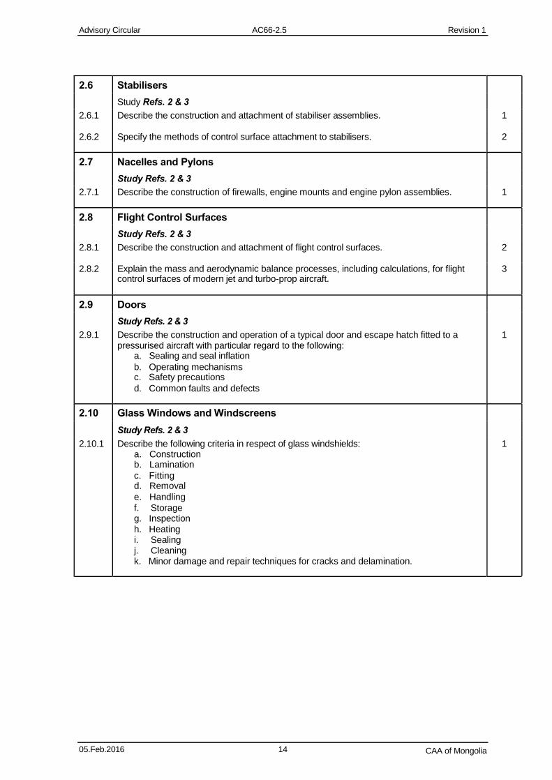
2.6 Stabilisers
Study Refs. 2 & 3
2.6.1 Describe the construction and attachment of stabiliser assemblies. 1 2.6.2 Specify the methods of control surface attachment to stabilisers. 2
2.7 Nacelles and Pylons
Study Refs. 2 & 3
2.7.1 Describe the construction of firewalls, engine mounts and engine pylon assemblies. 1
2.8 Flight Control Surfaces
Study Refs. 2 & 3
2.8.1 Describe the construction and attachment of flight control surfaces. 2
2.8.2 Explain the mass and aerodynamic balance processes, including calculations, for flight 3 control surfaces of modern jet and turbo-prop aircraft.
2.9 Doors
Study Refs. 2 & 3
2.9.1 Describe the construction and operation of a typical door and escape hatch fitted to a 1 pressurised aircraft with particular regard to the following:
a. Sealing and seal inflation
b. Operating mechanisms c. Safety precautions
d. Common faults and defects
2.10 Glass Windows and Windscreens
Study Refs. 2 & 3
2.10.1 Describe the following criteria in respect of glass windshields: 1 a. Construction b. Lamination
c. Fitting d. Removal
e. Handling
f. Storage g. Inspection h. Heating i. Sealing j. Cleaning k. Minor damage and repair techniques for cracks and delamination.
05.Feb.2016 14 CAA of Mongolia
Advisory Circular AC66-2.5 Revision 1
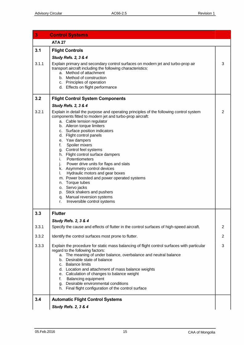
3 Control Systems
ATA 27
3.1 Flight Controls
Study Refs. 2, 3 & 4
3.1.1 Explain primary and secondary control surfaces on modern jet and turbo-prop air 3 transport aircraft including the following characteristics:
a. Method of attachment
b. Method of construction c. Principles of operation
d. Effects on flight performance
3.2 Flight Control System Components
Study Refs. 2, 3 & 4
3.2.1 Explain in detail the purpose and operating principles of the following control system 2 components fitted to modern jet and turbo-prop aircraft:
a. Cable tension regulator b. Aileron torque limiters
c. Surface position indicators d. Flight control panels
e. Yaw dampers f. Spoiler mixers g. Control feel systems h. Flight control surface dampers i. Potentiometers j. Power drive units for flaps and slats k. Asymmetry control devices l. Hydraulic motors and gear boxes
m. Power boosted and power operated systems n. Torque tubes
o. Servo jacks p. Stick shakers and pushers
q. Manual reversion systems r. Irreversible control systems
3.3 Flutter
Study Refs. 2, 3 & 4
3.3.1 Specify the cause and effects of flutter in the control surfaces of high-speed aircraft. 2
3.3.2 Identify the control surfaces most prone to flutter. 2 3.3.3 Explain the procedure for static mass balancing of flight control surfaces with particular 3
regard to the following factors: a. The meaning of under balance, overbalance and neutral balance
b. Desirable state of balance c. Balance limits
d. Location and attachment of mass balance weights e. Calculation of changes to balance weight
f. Balancing equipment g. Desirable environmental conditions h. Final flight configuration of the control surface
3.4 Automatic Flight Control Systems
Study Refs. 2, 3 & 4
05.Feb.2016 15 CAA of Mongolia
Advisory Circular AC66-2.5 Revision 1
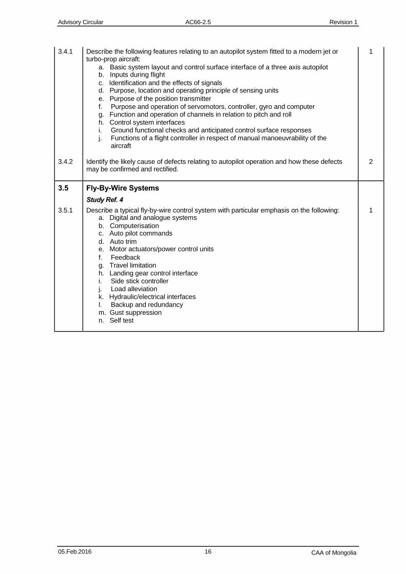
3.4.1 Describe the following features relating to an autopilot system fitted to a modern jet or 1 turbo-prop aircraft:
a. Basic system layout and control surface interface of a three axis autopilot b. Inputs during flight
c. Identification and the effects of signals d. Purpose, location and operating principle of sensing units
e. Purpose of the position transmitter
f. Purpose and operation of servomotors, controller, gyro and computer g. Function and operation of channels in relation to pitch and roll h. Control system interfaces i. Ground functional checks and anticipated control surface responses j. Functions of a flight controller in respect of manual manoeuvrability of the
aircraft
3.4.2 Identify the likely cause of defects relating to autopilot operation and how these defects 2 may be confirmed and rectified.
3.5 Fly-By-Wire Systems
Study Ref. 4
3.5.1 Describe a typical fly-by-wire control system with particular emphasis on the following: 1 a. Digital and analogue systems
b. Computerisation c. Auto pilot commands
d. Auto trim e. Motor actuators/power control units
f. Feedback g. Travel limitation h. Landing gear control interface i. Side stick controller j. Load alleviation k. Hydraulic/electrical interfaces l. Backup and redundancy m. Gust suppression n. Self test
05.Feb.2016 16 CAA of Mongolia
Advisory Circular AC66-2.5 Revision 1
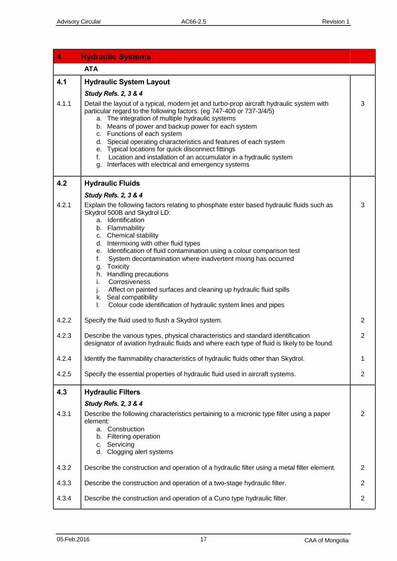
4 Hydraulic Systems
ATA
4.1 Hydraulic System Layout
Study Refs. 2, 3 & 4
4.1.1 Detail the layout of a typical, modern jet and turbo-prop aircraft hydraulic system with 3 particular regard to the following factors. (eg 747-400 or 737-3/4/5)
a. The integration of multiple hydraulic systems
b. Means of power and backup power for each system c. Functions of each system
d. Special operating characteristics and features of each system e. Typical locations for quick disconnect fittings
f. Location and installation of an accumulator in a hydraulic system g. Interfaces with electrical and emergency systems
4.2 Hydraulic Fluids
Study Refs. 2, 3 & 4
4.2.1 Explain the following factors relating to phosphate ester based hydraulic fluids such as 3 Skydrol 500B and Skydrol LD:
a. Identification
b. Flammability c. Chemical stability
d. Intermixing with other fluid types e. Identification of fluid contamination using a colour comparison test
f. System decontamination where inadvertent mixing has occurred g. Toxicity h. Handling precautions i. Corrosiveness j. Affect on painted surfaces and cleaning up hydraulic fluid spills k. Seal compatibility l. Colour code identification of hydraulic system lines and pipes
4.2.2 Specify the fluid used to flush a Skydrol system. 2
4.2.3 Describe the various types, physical characteristics and standard identification 2 designator of aviation hydraulic fluids and where each type of fluid is likely to be found.
4.2.4 Identify the flammability characteristics of hydraulic fluids other than Skydrol. 1
4.2.5 Specify the essential properties of hydraulic fluid used in aircraft systems. 2
4.3 Hydraulic Filters
Study Refs. 2, 3 & 4
4.3.1 Describe the following characteristics pertaining to a micronic type filter using a paper 2 element:
a. Construction b. Filtering operation
c. Servicing d. Clogging alert systems
4.3.2 Describe the construction and operation of a hydraulic filter using a metal filter element. 2
4.3.3 Describe the construction and operation of a two-stage hydraulic filter. 2
4.3.4 Describe the construction and operation of a Cuno type hydraulic filter. 2
05.Feb.2016 17 CAA of Mongolia
Advisory Circular AC66-2.5 Revision 1
4.4 Pressurised Reservoirs
Study Refs. 2, 3 & 4
4.4.1 State the following factors relating to pressurised hydraulic reservoirs: 2 a. The three main ways of reservoir pressurisation and the principles of operation
b. The components associated with each type of reservoir c. Why pressurisation of reservoirs is necessary
d. How pressure is controlled
4.5 Hydraulic Pumps
Study Refs. 2, 3 & 4
4.5.1 Specify the purpose, uses and principles of operation of the following types of hydraulic 2 pump:
a. Gear type pumps b. Gerotor type pumps
c. Double acting hand pumps d. Variable displacement axial-piston types
e. Ram air turbine/hydraulic pumps f. Bleed air driven pumps
4.5.2 Specify the effects of air entering a hydraulic pump during normal operation. 2
4.6 Hydraulic System Flow Control Valves
Study Refs. 2, 3 & 4
4.6.1 Describe the construction, operation, location and functions of the following hydraulic 2 system flow control valves:
a. Open and closed centre selector valves
b. Ball, cone, swing and orifice type in-line check valves including identification of
their correct flow direction c. Sequence valves
d. Selector valves including the four-way closed centre, spool-type and rotary valves
e. Priority valves
f. Quick or line disconnect valves g. Hydraulic fuses
4.7 Hydraulic System Pressure Control Devices
Study Refs. 2, 3 & 4
4.7.1 Describe the construction, operation, location and functions of the following hydraulic 2 system pressure control valves:
a. Relief valves (four and two port)
b. Pressure regulators including spool type regulators c. Pressure reducers
d. Accumulators (diaphragm, bladder and piston type) e. Thermal relief valves
f. De-boosters g. Cut-off valves h. Low demand fluid circulation devices i. System protection from overpressure damage
4.7.2 Describe the pressure adjustment sequence for multiple pressure regulating valves in a 2 hydraulic system.
4.7.3 State how a hydraulic accumulator is installed and charged. 2
05.Feb.2016 18 CAA of Mongolia
Advisory Circular AC66-2.5 Revision 1
4.7.4 Identify hydraulic pressures in a system relevant to the accumulator charge pressure. 2
4.7.5 Specify the cause of “hammering in a hydraulic system. 2
4.8 Actuating Cylinders and Hydraulic Motors
Study Refs. 2, 3 & 4
4.8.1 Describe the construction, operation and uses of the following actuating devices: 2 a. Single-action actuating cylinder b. Double-action actuating cylinder
c. Ported piston actuating cylinder d. Cushion-type linear actuator
e. Rack-and-pinion type linear actuators f. Piston-type rotary hydraulic motor
g. Balanced vane-type hydraulic motor
4.8.2 State the purpose and operation of a flap overload valve in a hydraulic flap operating 2 system.
4.9 Hydraulic Seals
Study Refs. 2, 3 & 4
4.9.1 Describe the construction, sealing operation, uses, installation, removal and tooling 2 associated with the following hydraulic seals and seal components:
a. One-way seals including, chevron, V-ring, U-ring, D-ring packings b. Two-way seals
c. O-rings d. Back-up rings (Teflon)
e. Seal materials
f. Seal compatibility g. Wipers
4.9.2 State the purpose of using back-up rings with “O” rings in high-pressure hydraulic 2 systems.
4.10 Hydraulic Indicating Systems
Study Ref. 2, 3 & 4
4.10.1 Explain typical hydraulic pressure, contents and temperature indicating systems and 3 their respective components.
4.11 Emergency Hydraulic Systems
Study Refs. 2, 3 & 4
4.11.1 Describe the principles of operation and components associated with emergency 2 hydraulic systems fitted to modern jet and turbo-prop air transport aircraft.
4.11.2 Describe the cause of kickback in an emergency hand pump handle. 2
4.11.3 Specify how and where fluid is stored in the hydraulic system for auxiliary or emergency 2 pump operation.
05.Feb.2016 19 CAA of Mongolia
Advisory Circular AC66-2.5 Revision 1
5 Landing Gear
ATA 32
5.1 Landing Gear System Configuration
Study Refs. 2 & 3
5.1.1 Describe the following landing gear configurations for modern jet and turbo-prop air 2 transport aircraft:
a. Dual main landing gear wheel arrangement b. “Bogie” truck main landing gear configuration
5.2 Landing Gear System Components
Study Refs. 2 & 3
5.2.1 Explain the function of the following components as appropriate to the above main 3 landing gear assemblies:
a. Pivot trunnion and trunnion beam b. Drag brace or strut
c. Upper and lower side braces d. Upper and lower shock strut cylinders
e. Torque link arms f. Positioner g. Equaliser h. Pivot beam, pivot fork and shafts i. Up and down-lock methods j. Down-lock bungee
5.3 Shock Struts
Study Refs. 2 & 3
5.3.1 Describe the construction and principles of operation of the following main landing gear 2 shock struts:
a. Metering pin type b. Metering tube type
c. Separator piston type 5.3.2 Specify the purpose, construction and operation of the following components. 2
a. Damping and snubbing devices
b. Mounting assemblies c. Glands and packings
d. Seals and backing rings e. Axles
5.3.3 Identify the fluids used in modern shock struts for load absorption or cushioning. 2
5.3.4 Describe the construction and operation of air charging valves fitted to shock strut 2 assemblies.
5.3.5 Detail a typical shock strut charging and bleeding procedures for separator and non- 3 separator type struts.
5.3.6 Explain how the correct shock strut fluid level would be established. 3
05.Feb.2016 20 CAA of Mongolia
Advisory Circular AC66-2.5 Revision 1
5.3.7 Describe the construction, location and operation of the following landing gear safety 2 devices:
a. Safety switch (Squat Switch) b. Cockpit located anti retraction devices
c. Ground locks d. Gear indicators
5.4 Landing Gear Rigging
Study Refs. 2 & 3
5.4.1 Specify the following rigging and adjustment procedures on common types of landing 2 gear:
a. Gear latching b. Gear door clearance
c. Drag and side brace adjustment d. Landing gear retraction
5.4.2 Describe a typical landing gear retraction check for a large transport aircraft. 2
5.4.3 Specify the function, operation and adjustment of the landing gear warning horn and give 2 likely reasons for horn malfunction.
5.5 Nose Wheel Steering Systems
Study Refs. 2 & 3
5.5.1 Detail the operation of a modern nose wheel steering system including the following 3 features:
a. Cockpit control
b. Mechanical, electrical or hydraulic linkages c. Metering or control valve in the control unit
d. Power sources e. Steering cylinders
f. Compensator/accumulator unit g. Pressurising assembly h. Follow up mechanism i. Safety valves j. Centring cam k. Differential assembly
5.6 Nose Wheel Shimmy Damping
Study Refs. 2 & 3
5.6.1 Describe the construction and operation of the following types of shimmy damper: 2 a. Piston type b. Vane type c. Steer damper
5.6.2 Identify the causes of nose wheel shimmy on large transport aircraft. 2
5.7 Retraction Systems
Study Refs. 2 & 3
5.7.1 Describe the construction and principles of operation of the following systems: 2 a. Electrical landing gear retraction systems b. Hydraulic landing gear retraction systems c. Emergency extension systems including hand operated pumps
5.7.2 Identify common undercarriage retraction faults, their likely cause and means of 2 indication in the cockpit.
05.Feb.2016 21 CAA of Mongolia
Advisory Circular AC66-2.5 Revision 1
5.8 Wheel Assemblies
Study Refs. 2 & 3
5.8.1 Specify the materials, construction and components, which make up the following types 2 of modern wheel assemblies:
a. Split wheel b. Removable flange wheels
c. Fixed flange, drop centre
5.8.2 Describe the types of wheel bearing that may be found in jet transport aircraft wheel 2 assemblies.
5.8.3 Describe how air leakage is prevented on split wheel assemblies using tubeless tyres. 2
5.9 Inspection of Wheel Assemblies
Study Ref. 2 & 3
5.9.1 Describe the following wheel inspections and specify typical defects that may be found: 2 a. NDT inspection of the castings b. Wheel bolt inspection
c. Key and key screw inspection d. Fusible plug inspection
e. Balance weights f. Corrosion inspection
5.10 Tyre Assemblies
Study Refs. 2 & 3
5.10.1 Define the following terms relating to modern aircraft tyre construction: 2 a. Tyre classification in terms of type, ply rating, tube or tubeless
b. Bead, bead toe, bead heel c. Carcass
d. Tread including, plain, all weather, rib and chine e. Breakers
f. Casing plies/cord body g. Flippers h. Chafers i. Inner liner j. Tread reinforcing ply, under tread k. Sidewall
l. Apex strip
m. Tube construction and selection
5.10.2 Specify the conditions and international rules relating to the use of radial ply tyres on 1 aircraft.
05.Feb.2016 22 CAA of Mongolia
Advisory Circular AC66-2.5 Revision 3
5.11 Maintenance of Tyres
Study Refs. 2 & 3
5.11.1 Describe the following factors relating to the maintenance of aircraft tyres: 2 a. Proper inflation for satisfactory service
b. The effects of under inflation and over inflation c. Sources of tyre pressure data
d. The effects of heat on tyre performance and life e. Actions to be taken if the fusible plug in the wheel melts
f. Tread condition including tread depth and wear pattern g. Tread damage h. Bead inspection and damage i. Sidewall condition and damage j. Bulges and broken cords k. Liner blistering
l. Thermal fuse inspection m. Allowance for nylon stretch
n. Tubeless air diffusion loss o. Lubrication of tubeless tyres during mounting
p. Pressure equalisation in dual tyres q. Overloading limitations and defects
r. Nylon flat spotting s. Tyre repair and repairable injuries including spot repairs
t. Tyre storage including avoidance of moisture and ozone u. Fuel and solvent hazards
v. Tube storage w. Tyre inspection and probing of injuries
x. Tyre mounting of tube type and tubeless tyres including inflation/deflation/re- inflation requirements
y. Tyre balancing z. Tyre inflation safety precautions aa. Venting of tubeless tyres bb. Initial stretch period cc. Demounting safety dd. Leaks or valve damage ee. Chevron cuts in the tyre centre resulting from the runway surface
ff. Retreading requirements and conditions including, top capping, full capping,
three-quarter retreads and bead to bead retreads gg. Uneven wear
hh. Wheel damage
ii. Tube inspection including valve stems, wrinkles, chafing, thinning jj. Use of a tyre pressure gauge
kk. Cleaning types after spills of fuel, oil or hydraulic fluid ll.
Balance and slippage marks mm. Gasses commonly used for tyre inflation
5.12 Operating Characteristics of Tyres
Study Ref. 2 & 3
5.12.1 Describe tyre characteristics under the following aircraft operating conditions: 2 a. Taxiing b. Braking and pivoting
c. Takeoff and landing d. Hydroplaning
05.Feb.2016 23 CAA of Mongolia
Advisory Circular AC66-2.5 Revision 1
5.13 Tyre Pressure Loss
Study Ref. 2 & 3
5.13.1 Describe the causes of air pressure loss in tubeless aircraft tyres under the following 2 conditions:
a. Damaged beads b. Improperly seated beads
c. Cut or puncture d. Air temperature
e. Venting
5.14 Assessment of Tyre Condition and Defects
Study Ref. 2 & 3
5.14.1 Diagnose from given information or pictures the following tyre conditions: 3 a. Normal and serviceable b. Worn out
c. Under inflation d. Over inflation
e. Open tread splice f. Thrown tread g. Peeled rib h. Tread chunking i. Cut j. Blister and tread separation k. Groove cracking and rib undercutting
l. Flaking and chipping m. Skid n. Tread rubber reversion
o. Chevron cutting p. Fabric fraying
q. Circumferential cracks r. Radial cracks s. Weather checking
t. Impact break u. Liner breakdown v. Contamination
w. Brake heat damage x. Chaff damage
5.15 Brake Assemblies
Study Ref. 2 & 3
5.15.1 Describe the construction and principles of operation of the following types of disk brake: 1
a. Expander tube (hydraulic and pneumatic) b. Multiple-disk
c. Segmented rotor d. Carbon
5.15.2 Give examples of the aircraft types where each brake system may be found. 1
5.15.3 Specify the type of operating system (hydraulic or pneumatic) appropriate to each brake 1 type.
05.Feb.2016 24 CAA of Mongolia
Advisory Circular AC66-2.5 Revision 1
5.16 Brake System Operation
Study Ref. 2 & 3
5.16.1 Detail the components, layout and principles of operation of the following systems: 3 a. Power boosted brake system
b. Power brake system c. Independent system
d. Power brake control valves e. Pressure ball-check brake control valve
f. Brake debooster cylinders and their likely location g. Emergency brake system and brake control valve functioning h. Auto-braking systems i. Automatic brake adjustment systems j. Inline valve for isolating the emergency brake system from the normal system k. Brake bleeder valve operation and brake pressure bleeding procedures
l. Emergency air brakes m. Master cylinders
n. Single and dual servo brakes
5.17 Brake Defects
Study Ref. 2 & 3
5.17.1 Diagnose the causes of the following brake system malfunctions: 3 a. Overheating b. Dragging
c. Chattering or squealing d. Unequal braking or brake pressure release in a high pressure system
5.18 Monitoring of Brake Temperature
Study Ref. 2 & 3
5.18.1 Describe a typical brake temperature monitoring system and apply limitation charts. 2
5.18.2 Describe the limitations relating to the application of park brakes when main brake 2 assemblies are hot.
5.19 Anti-skid Brake Control System
Study Ref. 2 & 3
5.19.1 Specify the purpose and operation of a typical antiskid control system with particular 2 regard to the following factors:
a. Independent interaction with wheel systems
b. Normal skid control c. Locked wheel skid control
d. Touchdown protection e. Fail safe protection
f. Arming devices and arming sequence g. Function and operation of the anti-skid warning light
5.19.2 State the purpose and operation of the following antiskid system components: 2 a. Wheel speed sensors b. Control valves
c. Control box d. Pilot control
5.19.3 Describe ground and in-flight testing and maintenance of an antiskid system. 2
05.Feb.2016 25 CAA of Mongolia
Advisory Circular AC66-2.5 Revision 1
6 Pneumatic Systems
ATA 36
6.1 Pneumatic System Layout
Study Ref. 2, 3 & 4
6.1.1 Specify a typical medium pressure pneumatic system layout for a modern turbo-prop 2 aircraft with particular emphasis on the relationship and placement of components.
6.1.2 Describe a pneumatic emergency brake actuating system for a large transport aircraft 2
with particular emphasis on the relationship and placement of components. 6.1.3 Specify aircraft components that would typically be operated by pneumatic power. 2 6.1.4 Describe where pneumatic air is normally vented or dumped during system operation. 2
6.1.5 Compare the advantages of using pneumatics over other aircraft power transmission 2 systems.
6.1.6 Compare the fundamental differences between hydraulic and pneumatic systems. 2
6.1.7 Compare the advantages and disadvantages and main differences between high, 2 medium and low pressure pneumatic systems.
6.1.8 Describe typical APU and ground cart air supply systems. 2
05.Feb.2016 26 CAA of Mongolia
Advisory Circular AC66-2.5 Revision 1
7 Pressurisation Systems
ATA 21
7.1 Terminology
Study Ref. 2, 3 & 4
7.1.1 Define the following terms and explain their application to aircraft pressurisation: 3 a. Cabin altitude b. Controlled leaks
c. Uncontrolled leaks d. Differential control mode
e. Differential pressure
f. Isobaric control mode g. Isobaric range h. Maximum differential i. Pressure altitude j. Rate control mode
7.2 Basic System Requirements
Study Ref. 2, 3 & 4
7.2.1 Detail the basic requirements for the successful functioning of a cabin pressurisation 3 system.
7.3 Pressurisation System Components
Study Ref. 2, 3 & 4
7.3.1 Determine from diagrams or schematic drawings the following pressurisation 3 components describing their construction and principles of operation:
a. Positive-displacement cabin compressors (superchargers) and their control
devices b. Supercharger instruments
c. Centrifugal cabin compressors d. Cabin altimeters
e. Cabin differential pressure indicators f. Cabin rate of climb indicators g. Jet pumps h. Negative pressure relief valves i. Outflow valves j. Pneumatic relays k. Cabin air pressure regulators l. Pressure controllers (automatic and manual)
m. Safety (positive pressure relief) valves and their operation n. Manually operated safety relief valves
o. Safety switches p. Pressurisation controls in the cockpit
q. Bleed air r. Turbo-charged bleed air s. Mass flow control
t. Temperature control u. Differential pressure v. Maximum pressure
7.4 System Layout
Study Ref. 2, 3 & 4
7.4.1 Describe a typical pressurisation system layout including the pneumatic or electrical 2 interconnection of components.
05.Feb.2016 27 CAA of Mongolia
Advisory Circular AC66-2.5 Revision 1
7.4.2 Determine the sources of cabin pressure on both older and modern types of gas turbine 3 and piston-powered aircraft.
7.5 Cabin Air Distribution
Study Ref. 2, 3 & 4
7.5.1 Detail a cabin air distribution system that includes the following components or 3 assemblies:
a. Ducts b. Filters
c. Heat exchangers d. Silencers
e. Non-return (check) valves
f. Humidifiers g. Mass flow control sensors h. Mass flow meters
7.5.2 Describe the importance of fuselage sealing to prevent airflow disruption particularly in 2 critical regions of the cabin.
7.6 System Operation
Study Ref. 2, 3 & 4
7.6.1 Describe a pressurisation system in the various modes of operation indicating the 2 functions of the components and the operation various electrical interface and warning/indication systems.
7.6.2 Describe how pressure is maintained for a pre-selected altitude. 2
7.6.3 State the factors that are sensed by the cabin pressurisation controller during normal 2 operation of the system.
7.7 Fault Finding and Maintenance
Study Ref. 2, 3 & 4
7.7.1 Diagnose faults in aircraft pressurisation systems including the electrical and instrument 3 interface and indicate how these faults can be rectified.
05.Feb.2016 28 CAA of Mongolia
Advisory Circular AC66-2.5 Revision 1
8 Air-conditioning Systems
ATA 21
8.1 General Functions
Study Ref. 2, 3 & 4
8.1.1 Detail the functions and requirements of an air-conditioning system. 3
8.2 Air-Conditioning Principles and Terminology
Study Ref. 2, 3 & 4
8.2.1 Define the following terms as they apply specifically to cabin atmosphere control 1 systems:
a. Adiabatic
b. Conduction c. Convection
d. Humidity e. Latent heat
f. Latent heat of vaporisation g. Radiation h. Relative humidity i. Sensible heat j. Superheat
8.3 Vapour Cycle System
Study Ref.
8.3.1 Describe the construction and operation of the following vapour cycle system 3 components:
a. Blowers
b. Compressors c. Condensers
d. Evaporators e. Expansion valves
f. Isolation valves g. Receiver-dryers h. Superheaters and subcoolers
8.3.2 Describe the construction features, principles of operation, location and function within a 2 typical system of the above components.
8.3.3 Describe the types and characteristics of refrigerants and oils used in an air conditioning 2 system.
8.3.4 Identify and state the function of the valves, gauges, fittings and hoses of a vapour cycle 2 servicing manifold set.
8.3.5 Describe the procedures and list the equipment used to carry out purging and charging 2 of the system.
8.3.6 State precautions necessary for the safe servicing of a vapour cycle system. 2
8.3.7 Describe the procedures and list the equipment used to carry out leak tests, checking 2 compressor oil and evacuating the system.
8.3.8 Identify and name the procedures to rectify faults in vapour cycle systems. 2 8.3.9 State the environmental requirements associated with the use of air conditioning fluids. 2
05.Feb.2016 29 CAA of Mongolia
Advisory Circular AC66-2.5 Revision 1
8.4 Air-Cycle System Components
Study Ref. 2, 3 & 4
8.4.1 From given schematic drawings, determine the relationships of the following air-cycle 3 system components and explain their operating principles:
a. Air-cycle machines b. Flow control valves
c. Expansion turbine d. Heat exchangers
e. Primary heat exchanger
f. Humidifiers g. Mixing chambers and mixing valves h. Pressure regulation valves i. Recirculation fans j. Recirculation filters k. Silencers
l. Spill valves m. Water separators (high and low pressure) n. Coalescent bags
8.5 Basic Air-Cycle System Layout and Operation
Study Ref. 2, 3 & 4
8.5.1 Identify by name and state the function of components in the basic air-cycle system. 2
8.5.2 Trace the airflow through the various schematic layouts provided. 2
8.6 Typical Aircraft Air-Cycle System Layout, Operation and Fault Finding
Study Ref. 2, 3 & 4
8.6.1 From given information, describe the operation and trace airflows in given configurations 2 including the electrical and instrument interface.
8.7 Temperature Control and Air Distribution
Study Ref. 2, 3 & 4
8.7.1 Describe desired airflow paths in occupied cabins. 2
8.7.2 Determine provisions for emergency and ground ventilation in given schematics. 3 8.7.3 From given information, describe the operation of a trim air system. 2
8.7.4 Describe the operating principles of gasper (eyeball) vents and the system. 2
8.7.5 Describe the operating principles of cabin temperature control systems and identify 2 appropriate sensor locations that contribute to stable temperature control.
8.7.6 Specify how and where thermistors would be used as a cabin temperature-sensing 2 device.
05.Feb.2016 30 CAA of Mongolia
Advisory Circular AC66-2.5 Revision 1
8.7.7 Describe the principles of operation of a typical combustion type heater used in 2 pressurised aircraft including the following features:
a. Output temperature control b. Fuel control
c. Ignition control d. Ventilation
e. Fire protection
f. Carbon monoxide testing g. Heater operating cycles h. Trouble shooting i. Defect rectification
8.7.8 State how cabin humidity is controlled with respect to the following criteria. 2
Reasons for humidification
Water separation
Humidity control system layout including interface with other cabin air-conditioning
systems Humidity control devices
05.Feb.2016 31 CAA of Mongolia
Advisory Circular AC66-2.5 Revision 1
9 Oxygen Systems
ATA 35
9.1 General
Study Ref. 2, 3 & 4
9.1.1 Define hypoxia, anoxia, hyperventilation and carbon monoxide poisoning and the 2 symptoms applying to them.
9.2 Forms of Oxygen
Study Ref. 2, 3 & 4
9.2.1 Describe the following forms of oxygen as used in aviation: 1 a. Gaseous
b. Liquid c. Chemical or solid state
d. Mechanically separated 9.2.2 Distinguish the differences between aviation breathing oxygen and oxygen available for 3
commercial or medical use.
9.3 Oxygen System and Associated Components
Study Ref. 2, 3 & 4
9.3.1 Detail the purpose, construction and operation of the following oxygen system 3 components:
a. High and low pressure cylinders b. Manual continuous flow regulators
c. Automatic continuous flow regulators d. Demand regulators
e. Diluter demand regulators f. Pressure demand regulators g. Airflow metering aneroid h. Continuous flow masks, re breather type masks or bags i. Demand type masks j. Filler valves k. Pressure gauges l. Continuous flow couplings m. Flow indicators n. Oxygen plumbing including materials used for rigid pipes and fittings
o. Smoke protection equipment p. Passenger service units
q. Charging valves r. Quantity and pressure indicators
9.4 Continuous Flow and Pressure Demand Systems
Study Ref. 2, 3 & 4
9.4.1 Detail the construction, layout and purpose of continuous flow and pressure demand 3 oxygen systems.
9.4.2 Specify how flow testing is carried out for each system. 2
05.Feb.2016 32 CAA of Mongolia
Advisory Circular AC66-2.5 Revision 1
9.5 Chemical Oxygen Systems
Study Ref. 2, 3 & 4
9.5.1 Describe the construction, layout and operation of a typical chemical oxygen system with 2 regard to the following criteria:
a. Candle construction b. Performance characteristics
c. Precautions
9.6 Portable Oxygen Equipment
Study Ref. 2, 3 & 4 9.6.1 Describe the construction, operation, performance limitations and uses of portable 2
oxygen equipment. 9.6.2 Specify how the contents of portable oxygen cylinders are checked. 2
9.7 System Advantages
Study Ref. 2, 3 & 4
9.7.1 Identify the features and compare the advantages and disadvantages of solid state 2 versus high-pressure gaseous oxygen systems.
9.7.2 Describe the type of system most commonly used for crew oxygen. 2
9.8 Oxygen System Servicing and Precautions
Study Ref. 2, 3 & 4
9.8.1 Explain oxygen system servicing with particular regard to the following factors: 3 a. Leak testing of gaseous oxygen systems and the materials that may be used
b. Used graphs or other technical date to establish leak rates against system gauge pressure
c. Cleaning system components d. Draining of the system
e. Purging the system and the purging gasses normally used
f. Filling the system g. Pressure/ temperature correction h. Filling a LOX system i. Inspecting masks and hoses j. Replacing tubing, valves and fittings k. Clearance between oxygen lines and electrical wiring l. Testing and lifing of cylinders and other components
m. Typical system inspection and maintenance procedures n. Maintenance of a typical oxygen dispensing trolley
o. Breathing oxygen cylinder identification (colour and lettering) p. Flaring and the types of flare used for rigid oxygen system lines
q. Typical charge pressures for the various types of oxygen cylinder
r. Colour code identification of oxygen system lines s. Testing of oxygen systems t. Use and maintenance of oxygen test equipment
9.8.2 Determine precautions to be taken to prevent oxygen fires and explosions. 3
05.Feb.2016 33 CAA of Mongolia
Advisory Circular AC66-2.5 Revision 1
10 Ice and Rain Protection Systems
ATA 30
10.1 General
Study Ref. 2, 3 & 4
10.1.1 Explain the types and formation processes relating to ice normally encountered in 2 aircraft operations.
10.1.2 Determine the parts of an aircraft normally susceptible to ice formation. 3
10.1.3 Detail the means employed on modern aircraft to prevent or control ice formation. 3
10.1.4 Explain the effects icing has on the operation or performance of an aeroplane and the 2 difference between anti-ice and de-icing systems.
10.2 Ice Detecting Devices
Study Ref. 2, 3 & 4
10.2.1 Detail the operation of the various types of ice detecting devices. 3
10.3 Pneumatic De Ice System
Study Ref. 2, 3 & 4
10.3.1 Detail the construction and operation of a typical pneumatic de-icing system with 3 particular regard to the following criteria:
a. Sources of operating air b. Configurations of pneumatic de-icer boots
c. De-icer boot inflation cycle d. De-icer boot construction and installation
e. Solenoid distributor valve f. Pumps g. Suction regulating valves h. Cockpit pressure and vacuum gauge indications when system operating
normally i. Unloading valves j. Relief valves k. Separators
l. Shuttle valves m. Timers
n. Retention of boots in the closed position when the system not operating
10.4 Pneumatic De-Ice System Maintenance
Study Ref. 2, 3 & 4
10.4.1 Detail typical inspections and operational checks associated with a pneumatic de-icing 3 system.
10.4.2 Describe typical de-icer boot repairs including the preparation of rubber and metal 2 surfaces prior to boot installation.
10.4.3 Specify how de-icer boots may be protected from damage or deterioration while in 2 service or in storage.
10.4.4 Detail typical de-icer system defects or malfunctions specifying associated causes and 3 remedies.
05.Feb.2016 34 CAA of Mongolia
Advisory Circular AC66-2.5 Revision 1
10.5 Thermal Anti-Ice Systems
Study Ref. 2, 3 & 4
10.5.1 Detail the construction and operation of thermal anti-ice systems with particular regard to 3 the following:
a. Wing anti-ice b. Engine inlet anti-ice
c. Windshield anti-ice d. Antenna anti-ice
e. Source of anti-ice air
f. Temperature control devices
10.5.2 Describe the components of a laminated integral electrically heated windshield system. 2
10.5.3 Detail the operation of a typical pitot head anti-ice system including physical and 3 electrical procedures and precautions for ground testing.
10.5.4 Diagnose the cause of overheating and arcing in an electrically heated windshield panel. 3 10.5.5 Describe the operation of a typical water and toilet drain heating system. 2
10.6 Chemical (Fluid) De-icing systems
Study Ref. 2, 3 & 4
10.6.1 Detail the construction, and operation of a typical chemical de-icing system including the 3 typical composition of the fluid used.
10.6.2 Detail the operation of a typical windshield de-icing system. 3
10.6.3 Describe the requirements for ground de-icing of aircraft, the chemicals used, and the 2 precautions associated with the use of de-ice chemicals.
10.7 Rain Control Systems
Study Ref. 2, 3 & 4
10.7.1 Detail the principles of operation and system layout of the following types of windscreen 3 rain removal systems:
a. Wiper b. Repellent (Chemical) c. Hot air (Pneumatic)
10.7.2 Describe the installation and adjustment of electric and hydraulic windscreen wiper 2
systems.
10.7.3 Specify how a pneumatic rain removal may be functionally tested. 2 10.7.4 Describe the operation of various types of windscreen demisting systems found on 2
modern aircraft.
05.Feb.2016 35 CAA of Mongolia
Advisory Circular AC66-2.5 Revision 1
11 Fuel Systems
ATA 28
11.1 General
Study Ref. 2, 3 & 4
11.1.1 Detail the layout of an air transport aircraft fuel system with particular regard to the 3 following criteria:
a. Standard symbols used to depict components
b. Integral fuel tank construction c. Purpose of baffles in an integral fuel tank
d. Cross feeding e. Fuel shut off
f. Emergency fire shut-off valves g. Fuel dumping/jettison including the typical numbers and locations of dump
chutes. h. Fuel heating i. Fuel icing indication devices j. Strainers and filters k. Booster and backing pumps including submerged single-speed centrifugal types l. Fuel pumps m. Fuelling stations n. Valves
o. Electrically operated devices p. Fuel tank transfer or “flapper” valves
q. Scavenging and jet pumps r. Ejector pumps
11.1.2 Describe how fuel is used for aircraft trim. 2
11.2 Fuel System Maintenance
Study Ref. 2, 3 & 4
11.2.1 Determine the following factors relating to aircraft fuel systems: 3 a. Re fuelling and de fuelling procedures
b. Function of a drip gauge and sight gauge for measurement of fuel tank contents c. The effects and control of static electricity
d. The cause and control of micro organisms in fuel tanks e. Fuel leak classification
f. Fire safety and hazard identification when re fuelling and de fuelling large aircraft
g. Fuel system contaminants likely to affect large jet and turbo-prop aircraft h. Removal of entrained and the hazards associated with water accumulation in
the fuel filters of gas turbine powered aircraft i. Gas to be used when purging an aircraft fuel tank j. Regulation of booster pump pressure k. Procedures and precautions associated with working inside aircraft fuel tanks l. Colour code identification of fuel pipes and lines
11.2.2 Detail precautions to be observed when pressure refuelling from hydrants or trucks. 3
11.3 Fuel Contents and Flow Measurement
Study Ref. 2, 3 & 4
11.3.1 Detail the construction and operation of a fuel contents and flow measurement system 3 for a large jet and turbo-prop aircraft.
05.Feb.2016 36 CAA of Mongolia
Advisory Circular AC66-2.5 Revision 1
11.3.2 State why fuel quantity is more likely specified in pounds rather than gallons on gas 2 turbine powered transport aircraft.
11.3.3 Detail the operation of a capacitance contents indicating system with particular regard to 3
the following features: a. Probe construction including dielectric
b. Contents calibration c. Electrical circuit
d. Trouble shooting and defect rectification
05.Feb.2016 37 CAA of Mongolia
Advisory Circular AC66-2.5 Revision 1
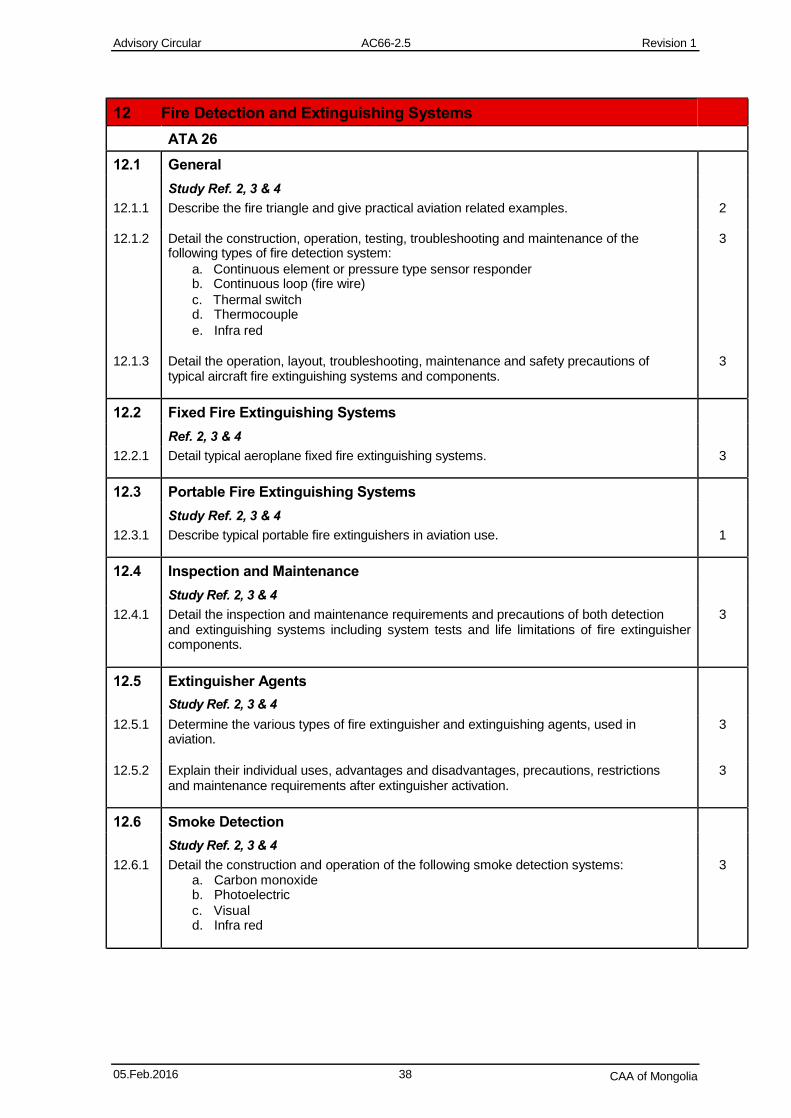
12 Fire Detection and Extinguishing Systems
ATA 26
12.1 General
Study Ref. 2, 3 & 4
12.1.1 Describe the fire triangle and give practical aviation related examples. 2
12.1.2 Detail the construction, operation, testing, troubleshooting and maintenance of the 3 following types of fire detection system:
a. Continuous element or pressure type sensor responder b. Continuous loop (fire wire)
c. Thermal switch d. Thermocouple
e. Infra red 12.1.3 Detail the operation, layout, troubleshooting, maintenance and safety precautions of 3
typical aircraft fire extinguishing systems and components.
12.2 Fixed Fire Extinguishing Systems
Ref. 2, 3 & 4
12.2.1 Detail typical aeroplane fixed fire extinguishing systems. 3
12.3 Portable Fire Extinguishing Systems
Study Ref. 2, 3 & 4
12.3.1 Describe typical portable fire extinguishers in aviation use. 1
12.4 Inspection and Maintenance
Study Ref. 2, 3 & 4
12.4.1 Detail the inspection and maintenance requirements and precautions of both detection 3 and extinguishing systems including system tests and life limitations of fire extinguisher components.
12.5 Extinguisher Agents
Study Ref. 2, 3 & 4
12.5.1 Determine the various types of fire extinguisher and extinguishing agents, used in 3 aviation.
12.5.2 Explain their individual uses, advantages and disadvantages, precautions, restrictions 3 and maintenance requirements after extinguisher activation.
12.6 Smoke Detection
Study Ref. 2, 3 & 4
12.6.1 Detail the construction and operation of the following smoke detection systems: 3 a. Carbon monoxide b. Photoelectric
c. Visual d. Infra red
05.Feb.2016 38 CAA of Mongolia
Advisory Circular AC66-2.5 Revision 1
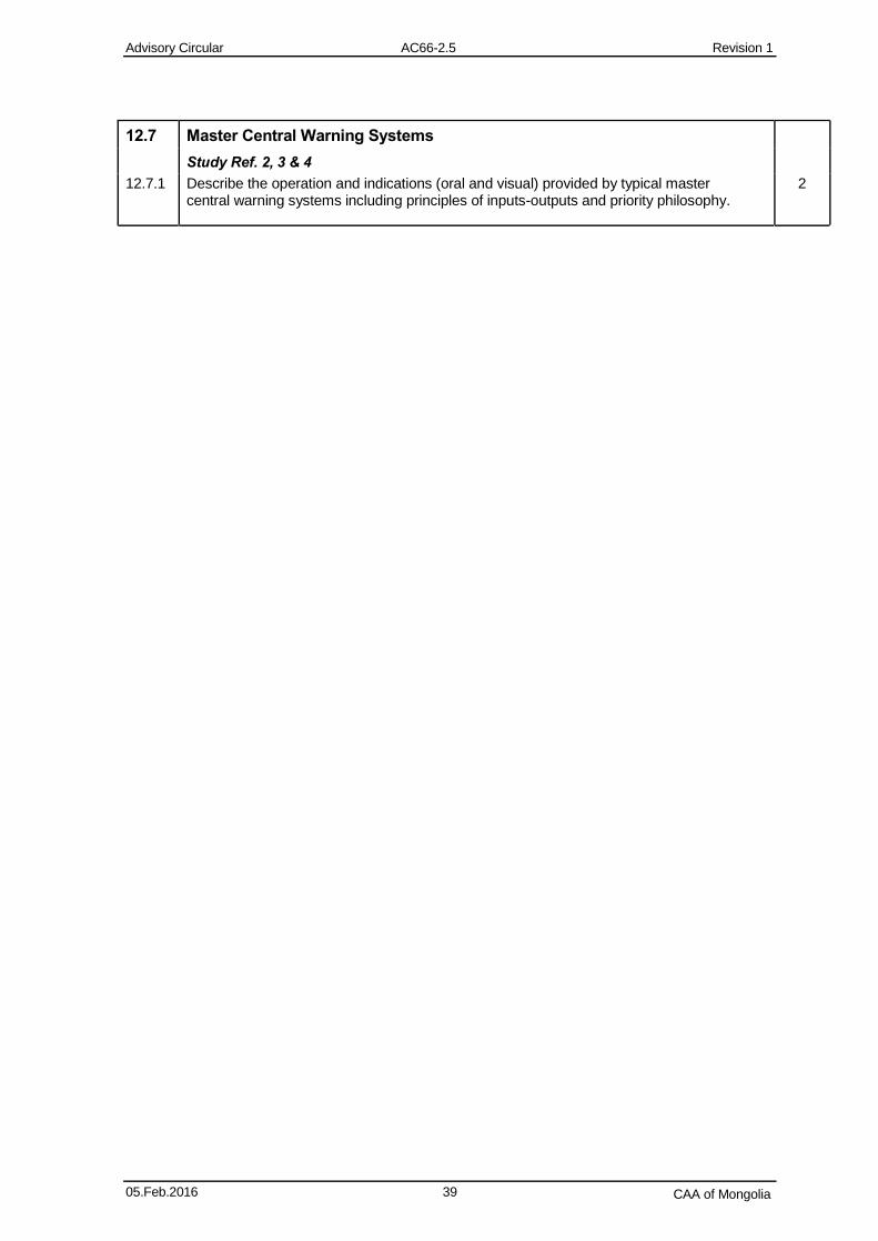
12.7 Master Central Warning Systems
Study Ref. 2, 3 & 4
12.7.1 Describe the operation and indications (oral and visual) provided by typical master 2 central warning systems including principles of inputs-outputs and priority philosophy.
05.Feb.2016 39 CAA of Mongolia
Advisory Circular AC66-2.5 Revision 1
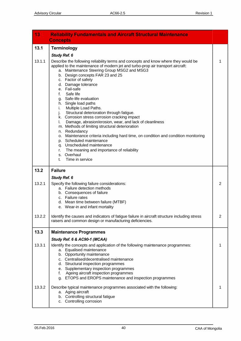
13 Reliability Fundamentals and Aircraft Structural Maintenance Concepts
13.1 Terminology
Study Ref. 6
13.1.1 Describe the following reliability terms and concepts and know where they would be 1 applied to the maintenance of modern jet and turbo-prop air transport aircraft:
a. Maintenance Steering Group MSG2 and MSG3
b. Design concepts FAR 23 and 25 c. Factor of safety
d. Damage tolerance e. Fail-safe
f. Safe life g. Safe-life evaluation h. Single load paths i. Multiple Load Paths. j. Structural deterioration through fatigue. k. Corrosion stress corrosion cracking impact
l. Damage, abrasion/erosion, wear, and lack of cleanliness m. Methods of limiting structural deterioration
n. Redundancy o. Maintenance criteria including hard time, on condition and condition monitoring
p. Scheduled maintenance q. Unscheduled maintenance
r. The meaning and importance of reliability s. Overhaul t. Time in service
13.2 Failure
Study Ref. 6
13.2.1 Specify the following failure considerations: 2 a. Failure detection methods b. Consequences of failure
c. Failure rates d. Mean time between failure (MTBF)
e. Wear-in and infant mortality
13.2.2 Identify the causes and indicators of fatigue failure in aircraft structure including stress 2 raisers and common design or manufacturing deficiencies.
13.3 Maintenance Programmes
Study Ref. 6 & AC90-1 (MCAA)
13.3.1 Identify the concepts and application of the following maintenance programmes: 1 a. Equalised maintenance b. Opportunity maintenance
c. Centralised/decentralised maintenance d. Structural inspection programmes
e. Supplementary inspection programmes f. Ageing aircraft inspection programmes
g. ETOPS and EROPS maintenance and inspection programmes
13.3.2 Describe typical maintenance programmes associated with the following: 1 a. Aging aircraft b. Controlling structural fatigue c. Controlling corrosion
05.Feb.2016 40 CAA of Mongolia
Advisory Circular AC66-2.5 Revision 1
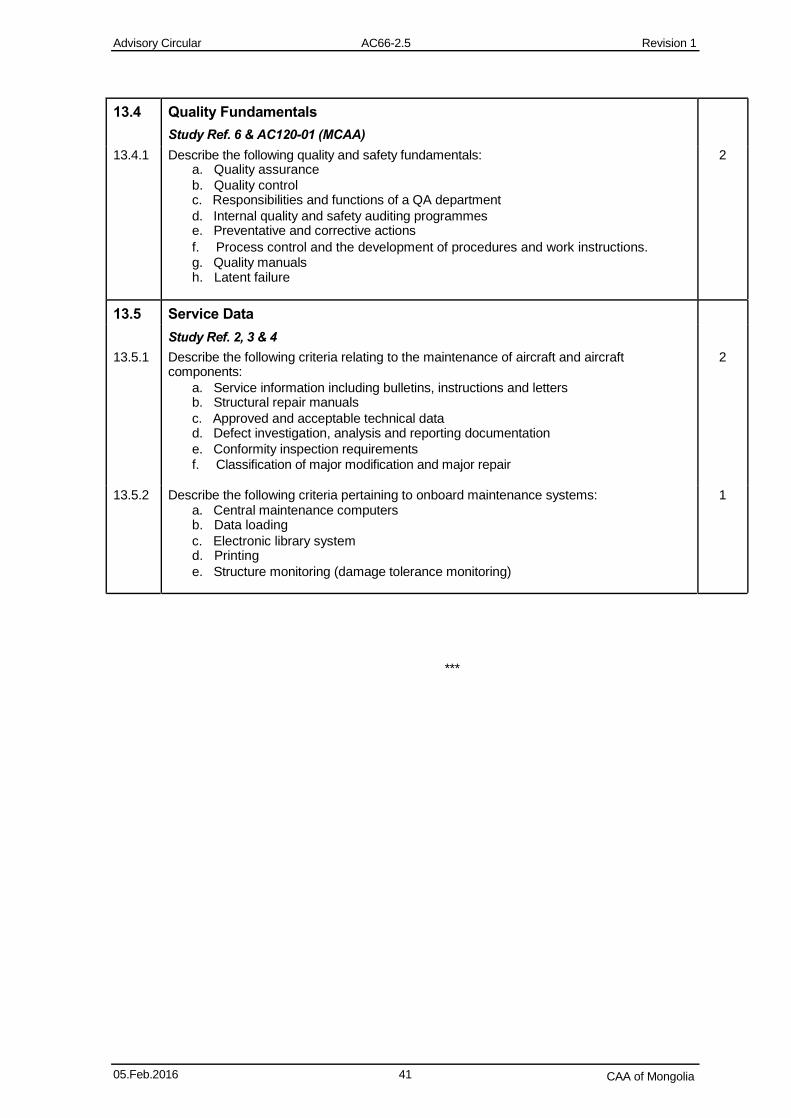
13.4 Quality Fundamentals
Study Ref. 6 & AC120-01 (MCAA)
13.4.1 Describe the following quality and safety fundamentals: 2 a. Quality assurance
b. Quality control c. Responsibilities and functions of a QA department
d. Internal quality and safety auditing programmes e. Preventative and corrective actions
f. Process control and the development of procedures and work instructions. g. Quality manuals h. Latent failure
13.5 Service Data
Study Ref. 2, 3 & 4
13.5.1 Describe the following criteria relating to the maintenance of aircraft and aircraft 2 components:
a. Service information including bulletins, instructions and letters b. Structural repair manuals
c. Approved and acceptable technical data d. Defect investigation, analysis and reporting documentation
e. Conformity inspection requirements f. Classification of major modification and major repair
13.5.2 Describe the following criteria pertaining to onboard maintenance systems: 1 a. Central maintenance computers b. Data loading
c. Electronic library system d. Printing
e. Structure monitoring (damage tolerance monitoring)
***
05.Feb.2016 41 CAA of Mongolia