Embed Size (px)
Citation preview
Prepared for
U.S. Department of EnergyOffice of Environmental Management
Office of Science and Technology
August 1999
AEA FluidicPulse JetMixer
Tanks Focus Area
DOE/EM-0447
Demonstrated atOak Ridge National Laboratory
Oak Ridge, Tennessee
AEA FluidicPulse Jet Mixer
OST Reference #1511
Tanks Focus Area
Purpose of this document
Innovative Technology Summary Reports are designed to provide potential users with theinformation they need to quickly determine if a technology would apply to a particularenvironmental management problem. They are also designed for readers who mayrecommend that a technology be considered by prospective users.
Each report describes a technology, system, or process that has been developed and testedwith funding from DOE’s Office of Science and Technology (OST). A report presents the fullrange of problems that a technology, system, or process will address and its advantages to theDOE cleanup in terms of system performance, cost, and cleanup effectiveness. Most reportsinclude comparisons to baseline technologies as well as other competing technologies.Information about commercial availability and technology readiness for implementation is alsoincluded. Innovative Technology Summary Reports are intended to provide summary information.References for more detailed information are provided in an appendix.
Efforts have been made to provide key data describing the performance, cost, and regulatoryacceptance of the technology. If this information was not available at the time of publication,the omission is noted.
All published Innovative Technology Summary Reports are available onthe OST Web site athttp://ost.em.doe.gov under “Publications.”
A
B
6
4
APPENDICES
7
5
2
1
TABLE OF CONTENTS
3
Page 1SUMMARY
Page 17LESSONS LEARNED
Page 15REGULATORY AND POLICY ISSUES
Page 13COST
Page 10TECHNOLOGY APPLICABILITY ANDALTERNATIVES
Page 7PERFORMANCE
Page 3TECHNOLOGY DESCRIPTION
References
Acronyms and Abbreviations
1United States Department of Energy
SECTION 1
SUMMARY
Hundreds of U.S. Department of Energy (DOE) underground storage tanks contain radioactive wasterequiring remediation. After many years of storage, the wastes have separated into layers of liquid andsludge. Remediation of these tanks involves waste removal and processing to stabilize the radioactive andhazardous components for long-term disposal. The heavy layer of sludge must be mobilized to remove itfrom a tank. A preferred method involves mixing the sludge with existing tank liquids rather than adding moreliquids and increasing the waste volume. This approach produces slurry that can be easily removed from atank.
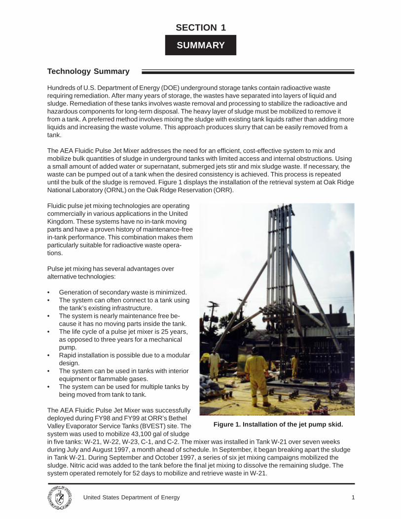
The AEA Fluidic Pulse Jet Mixer addresses the need for an efficient, cost-effective system to mix andmobilize bulk quantities of sludge in underground tanks with limited access and internal obstructions. Usinga small amount of added water or supernatant, submerged jets stir and mix sludge waste. If necessary, thewaste can be pumped out of a tank when the desired consistency is achieved. This process is repeateduntil the bulk of the sludge is removed. Figure 1 displays the installation of the retrieval system at Oak RidgeNational Laboratory (ORNL) on the Oak Ridge Reservation (ORR).
Fluidic pulse jet mixing technologies are operatingcommercially in various applications in the UnitedKingdom. These systems have no in-tank movingparts and have a proven history of maintenance-freein-tank performance. This combination makes themparticularly suitable for radioactive waste opera-tions.
Pulse jet mixing has several advantages overalternative technologies:
• Generation of secondary waste is minimized.• The system can often connect to a tank using
the tank’s existing infrastructure.• The system is nearly maintenance free be-
cause it has no moving parts inside the tank.• The life cycle of a pulse jet mixer is 25 years,
as opposed to three years for a mechanicalpump.
• Rapid installation is possible due to a modulardesign.
• The system can be used in tanks with interiorequipment or flammable gases.
• The system can be used for multiple tanks bybeing moved from tank to tank.
The AEA Fluidic Pulse Jet Mixer was successfullydeployed during FY98 and FY99 at ORR’s BethelValley Evaporator Service Tanks (BVEST) site. Thesystem was used to mobilize 43,100 gal of sludgein five tanks: W-21, W-22, W-23, C-1, and C-2. The mixer was installed in Tank W-21 over seven weeksduring July and August 1997, a month ahead of schedule. In September, it began breaking apart the sludgein Tank W-21. During September and October 1997, a series of six jet mixing campaigns mobilized thesludge. Nitric acid was added to the tank before the final jet mixing to dissolve the remaining sludge. Thesystem operated remotely for 52 days to mobilize and retrieve waste in W-21.
Figure 1. Installation of the jet pump skid.
Technology Summary
2 United States Department of Energy
Demonstration Summary
Contacts
Tank W-22 operations took place in January and February 1998, and W-23 operations occurred in April andMay 1998. The C-1 and C-2 removals took place in February and March 1999. After completion of the C tankmixing operations, tank W-23 was mixed for seven days in March 1999 before final waste removal.
• This technology minimized the amount of additional waste created by using existing liquids for most ofthe additions.
• The system operated in multiple tanks by using existing pipe system cross-connections.• The rapid installation alone resulted in a 30 percent cost savings over alternative technologies.• The system achieved at least a 75 percent cost savings and a 50 percent schedule improvement.
The following parties contributed to successful deployment of the AEA Fluidic Pulse Jet Mixer:
• AEA Technology developed and fabricated the system and provided oversight and training.• Tanks Focus Area supported AEA Technology in adapting the system for the ORNL application.• DOE–Oak Ridge Office of Waste Management supported system adaptation and implementation.• DOE–Oak Ridge Transuranic Waste Program Management provided leadership and established goals.• Bechtel Jacobs Company managed the project and provided engineering support.• Lockheed Martin Energy Research and Energy Systems designed installation interfaces and provided
suppport in the areas of safety, engineering, field operations, and documentation.• MK-Ferguson installed the system, supported radiation protection, and fabricated and operated a
sluicer.• Solutions to Environmental Problems, Inc. provided photographic and video coverage of operations.
ORR plans to deploy similar equipment at additional tanks. The system will also be used in FY99 todemonstrate mixing of a pump tank at Savannah River Site (SRS). Full deployment is being pursued throughthe Accelerated Site Technology Deployment Program.
TechnicalTim E. Kent, Principal Investigator, Oak Ridge National Laboratory, Phone: (423) 576-8592, E-mail:[email protected]
Laurie Judd, Vice President for Federal Programs, AEA Technology, Phone: (703) 748-4810, E-mail:[email protected] (Mr. Judd fields technical questions. Technical contacts travel extensively.)
ManagementTed Pietrok, Tanks Focus Area Management Team Lead, DOE-RL, Richland, Washington, (509) 372-4546,E-mail: [email protected]
Kurt Gerdes, Program Manager, EM-53, DOE, Germantown, Maryland, (301) 903-7289, E-mail:[email protected]
Jacquie Noble-Dial, Oak Ridge Operations Tanks Focus Area Manager, DOE, Phone: (423) 241-6184,E-mail: [email protected]
OtherAll published Innovative Technology Summary Reports are available on the OST Web site at http://ost.em.doe.gov under “Publications.” The Technology Management System, also available through the OSTWeb site, provides information about OST programs, technologies, and problems. The OST referencenumber for the AEA Fluidic Pulse Jet Mixer is 1511.
3United States Department of Energy
Overall Process Definition
SECTION 2
TECHNOLOGY DESCRIPTION
Goals for demonstrating AEA’s Fluidic Pulse Jet Mixer included the following:
• Evaluate a system for efficiently mixing radioactive waste in underground storage tanks to mobilize thesludge for removal.
• Perform these activities in a cost-effective manner.• Reduce time required to complete activities.• Reduce risks.• Minimize generation of secondary waste.
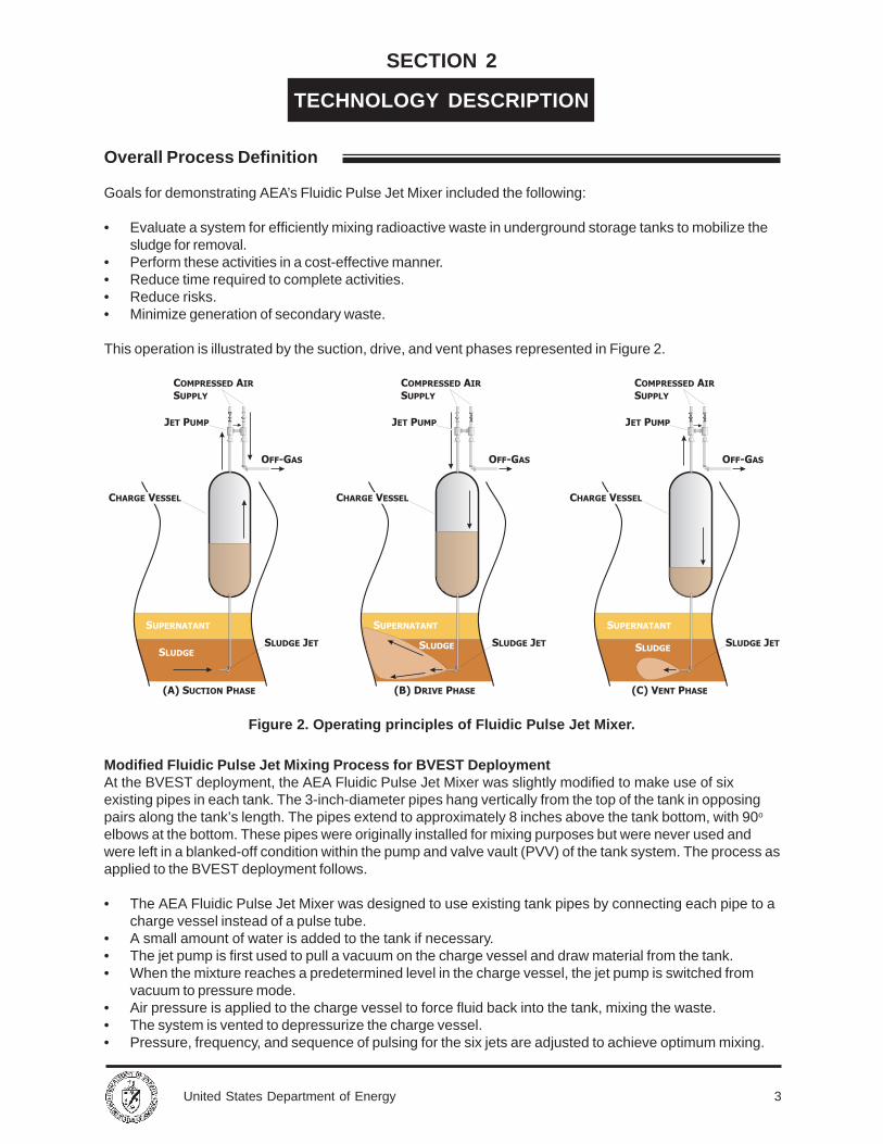
This operation is illustrated by the suction, drive, and vent phases represented in Figure 2.
Figure 2. Operating principles of Fluidic Pulse Jet Mixer.
Modified Fluidic Pulse Jet Mixing Process for BVEST DeploymentAt the BVEST deployment, the AEA Fluidic Pulse Jet Mixer was slightly modified to make use of sixexisting pipes in each tank. The 3-inch-diameter pipes hang vertically from the top of the tank in opposingpairs along the tank’s length. The pipes extend to approximately 8 inches above the tank bottom, with 90o
elbows at the bottom. These pipes were originally installed for mixing purposes but were never used andwere left in a blanked-off condition within the pump and valve vault (PVV) of the tank system. The process asapplied to the BVEST deployment follows.
• The AEA Fluidic Pulse Jet Mixer was designed to use existing tank pipes by connecting each pipe to acharge vessel instead of a pulse tube.
• A small amount of water is added to the tank if necessary.• The jet pump is first used to pull a vacuum on the charge vessel and draw material from the tank.• When the mixture reaches a predetermined level in the charge vessel, the jet pump is switched from
vacuum to pressure mode.• Air pressure is applied to the charge vessel to force fluid back into the tank, mixing the waste.• The system is vented to depressurize the charge vessel.• Pressure, frequency, and sequence of pulsing for the six jets are adjusted to achieve optimum mixing.
4 United States Department of Energy
The general process operates using only the suction and vent phases shown in Figure 2, while the modifiedprocess for the BVEST deployment uses all three phases: suction, drive, and vent.
Key Elements of the Technology and Support Equipment/SystemsThe AEA Fluidic Pulse Jet Mixer deployed at ORR consists of the following seven equipment modules:
• Two charge vessel skids• Jet pump skid• Valve skid• Off-gas skid• Pipe bridge skid• Control cubicle
Other notable aspects of the technology include:
• The valve skid, jet pump skid, and charge vessel skids were constructed of 304L stainless steel forcorrosion resistance to the waste and compatibility with acidic cleaning solutions.
• Charge vessel skids were installed within the PVV at the ORR site, while the other skids were locatedon top of and adjacent to the BVEST vault cover. A separate trailer was used to house controls that areused to operate and monitor the system.
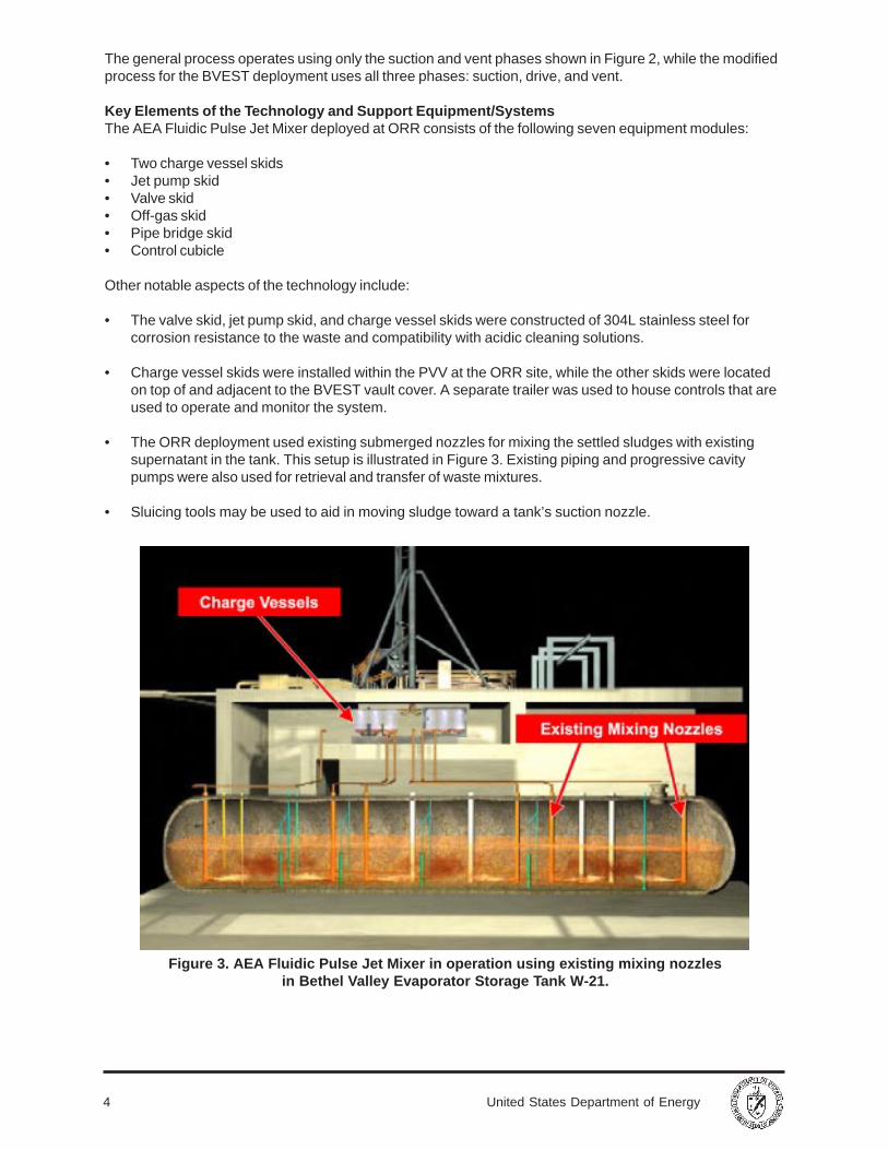
• The ORR deployment used existing submerged nozzles for mixing the settled sludges with existingsupernatant in the tank. This setup is illustrated in Figure 3. Existing piping and progressive cavitypumps were also used for retrieval and transfer of waste mixtures.
• Sluicing tools may be used to aid in moving sludge toward a tank’s suction nozzle.
Figure 3. AEA Fluidic Pulse Jet Mixer in operation using existing mixing nozzlesin Bethel Valley Evaporator Storage Tank W-21.
5United States Department of Energy
System Operation
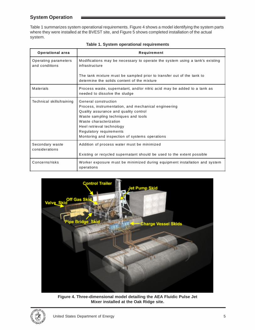
Figure 4. Three-dimensional model detailing the AEA Fluidic Pulse JetMixer installed at the Oak Ridge site.
Table 1. System operational requirements
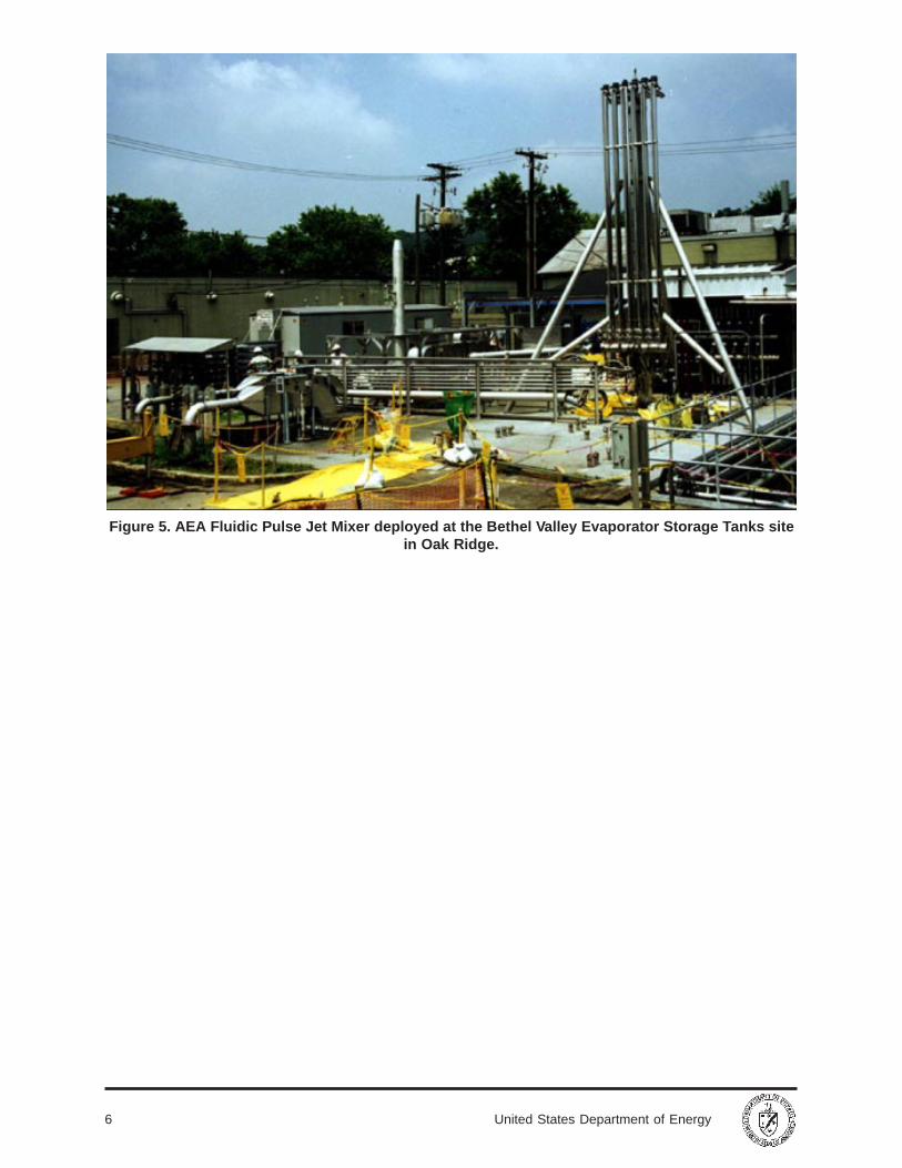
Table 1 summarizes system operational requirements. Figure 4 shows a model identifying the system partswhere they were installed at the BVEST site, and Figure 5 shows completed installation of the actualsystem.
Operational area Requirement
Operating parametersand conditions
Modifications may be necessary to operate the system using a tank's existinginfrastructure
The tank mixture m ust be sampled prior to transfer out of the tank todeterm ine the solids content of the m ixture
Materials Process waste, supernatant, and/or nitric acid may be added to a tank asneeded to dissolve the sludge
Technical skills/training General constructionProcess, instrumentation, and mechanical engineeringQuality assurance and quality controlWaste sam pling techniques and toolsWaste characterizationHeel retrieval technologyRegulatory requirementsMontoring and inspection of systems operations
Secondary wasteconsiderations
Addition of process water must be minimized
Existing or recycled supernatant should be used to the extent possible
Concerns/risks Worker exposure m ust be minimized during equipm ent installation and systemoperations
6 United States Department of Energy
Figure 5. AEA Fluidic Pulse Jet Mixer deployed at the Bethel Valley Evaporator Storage Tanks sitein Oak Ridge.
7United States Department of Energy
SECTION 3
PERFORMANCE
Demonstration Plan
In FY97, AEA Technology modified the mixer to meet ORNL’s specifications and completed a cold test inApril 1997. The equipment was installed at the BVEST site in July 1997. Following commissioning, W-21mixing operations were started in September 1997. Operations (including the tanks W-21, W-22, W-23, C-1,and C-2) continued into FY99. The BVEST site is located in the center of ORNL’s main plant area andcontains five horizontal, stainless steel storage tanks in underground, concrete vaults. These tanks are 12 ftin diameter and 61.5 ft long, with a capacity of 50,000 gal. They store evaporator concentrate and diluteradioactive liquid low-level waste. Radiation levels up to 27 rad/h have been detected in and around thetanks. Precipitants from the cooled evaporator waste formed a sludge layer 3–5 ft deep in the tanks.
DOE’s major objective for deploying the AEA Fluidic Pulse Jet Mixer was to improve upon existing technol-ogy used to mobilize sludge to advance and refine the overall cleanup effort. Desired improvements included
• reducing time required for operations, leading to accelerated cleanup schedules, and• reducing waste volumes in the tanks.
Table 2 lists the major elements evaluated during the deployment.
Table 2. Major elements evaluated during deployment of the AEA Fluidic Pulse Jet Mixer
All success criteria listed in Table 2 were achieved. Notable details follow.
• The system was installed in Tank W-21 and commissioned in approximately seven weeks.
• Installation was completed a month ahead of schedule, yielding a 30 percent cost savings.
• A tank inspection after the first waste transfer showed that jet mixing was able to mobilize the sludge inW-21, W-22, and W-23 for transfer out of the tank.
• Manual sluicing in Tank W-21 was successful in moving sludge from the nozzle areas and tank endstoward the tank’s suction nozzle, where the fixed pulse jets were less effective.
• Tanks W-21, W-22, and W-23 were emptied in months, as opposed to an estimated three years toempty only one tank using alternative technology.
System Performance
Element Success criteria
Installation The system 's modular design shall enable faster, easier installation
Maintenance Maintenance shall be minimal
Mixing The system shall effectively m obilize sludge in a timely manner
Risks/hazards/safety Risk management shall include appropriate procedures, actions, and protectivemeasures to mitigate potential risks and hazards and provide a safe environmentfor workers and the public
Cost The system shall generate costs savings over baseline technologies
Schedule Process com pletion time shall be less than that of alternative technologies
8 United States Department of Energy
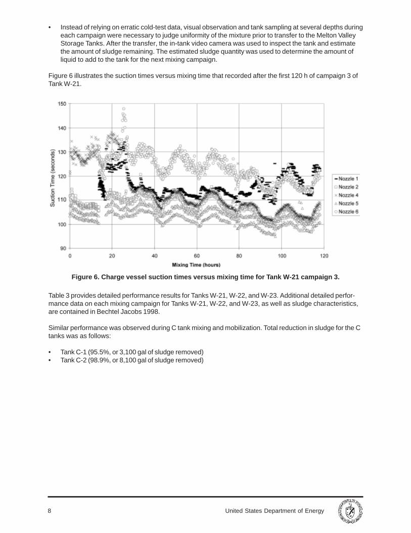
Figure 6. Charge vessel suction times versus mixing time for Tank W-21 campaign 3.
• Instead of relying on erratic cold-test data, visual observation and tank sampling at several depths duringeach campaign were necessary to judge uniformity of the mixture prior to transfer to the Melton ValleyStorage Tanks. After the transfer, the in-tank video camera was used to inspect the tank and estimatethe amount of sludge remaining. The estimated sludge quantity was used to determine the amount ofliquid to add to the tank for the next mixing campaign.
Figure 6 illustrates the suction times versus mixing time that recorded after the first 120 h of campaign 3 ofTank W-21.
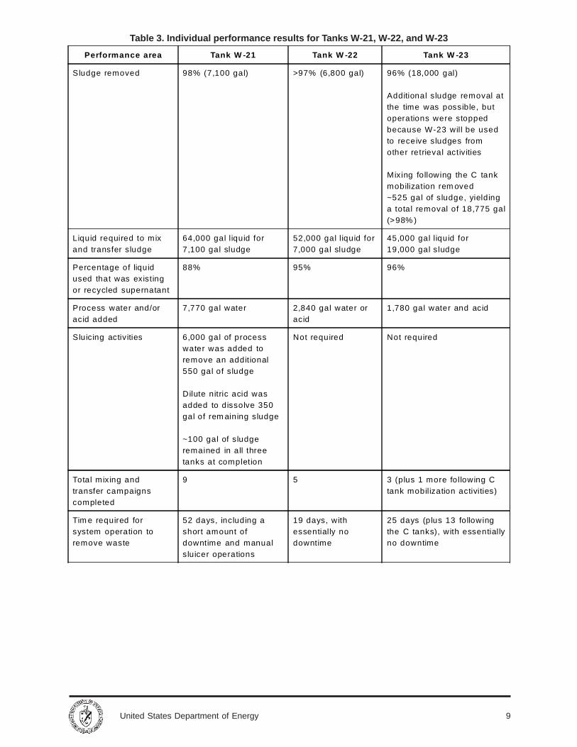
Table 3 provides detailed performance results for Tanks W-21, W-22, and W-23. Additional detailed perfor-mance data on each mixing campaign for Tanks W-21, W-22, and W-23, as well as sludge characteristics,are contained in Bechtel Jacobs 1998.
Similar performance was observed during C tank mixing and mobilization. Total reduction in sludge for the Ctanks was as follows:
• Tank C-1 (95.5%, or 3,100 gal of sludge removed)• Tank C-2 (98.9%, or 8,100 gal of sludge removed)
9United States Department of Energy
Table 3. Individual performance results for Tanks W-21, W-22, and W-23
Performance area Tank W -21 Tank W -22 Tank W -23
Sludge removed 98% (7,100 gal) >97% (6,800 gal) 96% (18,000 gal)
Additional sludge removal atthe time was possible, butoperations were stoppedbecause W-23 will be usedto receive sludges fromother retrieval activities
Mixing following the C tankmobilization rem oved~525 gal of sludge, yieldinga total removal of 18,775 gal(>98% )
Liquid required to mixand transfer sludge
64,000 gal liquid for7,100 gal sludge
52,000 gal liquid for7,000 gal sludge
45,000 gal liquid for19,000 gal sludge
Percentage of liquidused that was existingor recycled supernatant
88% 95% 96%
Process water and/oracid added
7,770 gal water 2,840 gal water oracid
1,780 gal water and acid
Sluicing activities 6,000 gal of processwater was added toremove an additional550 gal of sludge
Dilute nitric acid wasadded to dissolve 350gal of rem aining sludge
~100 gal of sludgeremained in all threetanks at completion
Not required Not required
Total mixing andtransfer campaignscompleted
9 5 3 (plus 1 more following Ctank mobilization activities)
Tim e required forsystem operation toremove waste
52 days, including ashort amount ofdowntime and manualsluicer operations
19 days, withessentially nodowntime
25 days (plus 13 followingthe C tanks), with essentiallyno downtime
10 United States Department of Energy
SECTION 4
TECHNOLOGY APPLICABILITYAND ALTERNATIVES
Competing Technologies
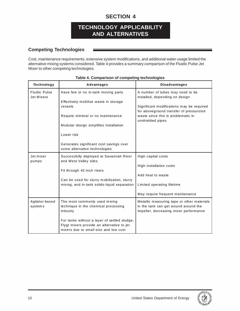
Cost, maintenance requirements, extensive system modifications, and additional water usage limited thealternative mixing systems considered. Table 4 provides a summary comparison of the Fluidic Pulse JetMixer to other competing technologies.
Table 4. Comparison of competing technologies
Technology Advantages Disadvantages
Fluidic PulseJet M ixers
Have few or no in-tank moving parts
Effectively mobilize waste in storagevessels
Require minimal or no maintenance
Modular design simplifies installation
Lower risk
Generates significant cost savings oversome alternative technologies
A number of tubes may need to beinstalled, depending on design
Significant modifications m ay be requiredfor aboveground transfer of pressurizedwaste since this is problematic inunshielded pipes
Jet m ixerpumps
Successfully deployed at Savannah Riverand West Valley sites
Fit through 42-inch risers
Can be used for slurry m obilization, slurrymixing, and in-tank solids-liquid separation
High capital costs
High installation costs
Add heat to waste
Limited operating lifetime
May require frequent maintenance
Agitator-basedsystem s
The most commonly used m ixingtechnique in the chemical processingindustry
For tanks without a layer of settled sludge,Flygt mixers provide an alternative to jetmixers due to small size and low cost
Metallic m easuring tape or other materialsin the tank can get wound around theimpeller, decreasing mixer performance
11United States Department of Energy
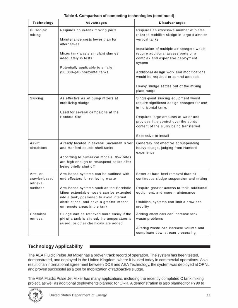
Table 4. Comparison of competing technologies (continued)
Technology Advantages Disadvantages
Pulsed-airmixing
Requires no in-tank m oving parts
Maintenance costs lower than foralternatives
Mixes tank waste simulant slurriesadequately in tests
Potentially applicable to smaller(50,000-gal) horizontal tanks
Requires an excessive number of plates(~64) to mobilize sludge in large-diametervertical tanks
Installation of multiple air spargers wouldrequire additional access ports or acomplex and expensive deploym entsystem
Additional design work and modificationswould be required to control aerosols
Heavy sludge settles out of the mixingplate range
Sluicing As effective as jet pump mixers atmobilizing sludge
Used for several campaigns at theHanford Site
Single-point sluicing equipment wouldrequire significant design changes for usein horizontal tanks
Requires large amounts of water andprovides litt le control over the solidscontent of the slurry being transferred
Expensive to install
Air-liftcirculators
Already located in several Savannah Riverand Hanford double-shell tanks
According to numerical models, flow ratesare high enough to resuspend solids afterbeing briefly shut off
Generally not effective at suspendingheavy sludge, judging from Hanfordexperience
Arm - orcrawler-basedretrievalmethods
Arm -based systems can be outfitted withend effectors for retrieving waste
Arm -based systems such as the BoreholeMiner extendable nozzle can be extendedinto a tank, positioned to avoid internalobstructions, and have a greater im pacton rem ote areas in the tank
Better at hard heel removal than atcontinuous sludge suspension and mixing
Require greater access to tank, additionalequipment, and more m aintenance
Umbilical systems can limit a crawler'smobility
Chemicalretrieval
Sludge can be retrieved more easily if thepH of a tank is altered, the tem perature israised, or other chemicals are added
Adding chem icals can increase tankwaste problem s
Altering waste can increase volum e andcomplicate downstream processing
The AEA Fluidic Pulse Jet Mixer has a proven track record of operation. The system has been tested,demonstrated, and deployed in the United Kingdom, where it is used today in commercial operations. As aresult of an international agreement between DOE and AEA Technology, the system was deployed at ORNLand proven successful as a tool for mobilization of radioactive sludge.
The AEA Fluidic Pulse Jet Mixer has many applications, including the recently completed C tank mixingproject, as well as additional deployments planned for ORR. A demonstration is also planned for FY99 to
Technology Applicability
12 United States Department of Energy
Patents/Commercialization/Sponsors
demonstrate mixing of a pump tank at SRS. Full deployment for additional tanks is being pursued throughthe Accelerated Site Technology Deployment Program. Other potential sites for deployment include theHanford Reservation and Idaho National Engineering and Environmental Laboratory.
Considerations that favor selecting this technology for future application are as follows:
• The system has a proven track record for mobilization of sludge for retrieval.• The technology can be applied to both horizontal and vertical tanks.• The system was used on multiple tanks using existing cross-connections.• The life span of a fluidic pulse jet pump is 25 years.• Other cost savings can be realized through rapid installation, faster operations, and elimination/reduc-
tion of maintenance.
The AEA Fluidic Pulse Jet Mixer is commercially available from AEA Technology. Patent status is unclearat this time and is being researched by AEA Technology.
DOE sponsored the ORR deployment. Key parties involved with development and implementation of thistechnology are listed in Section 1 under Demonstration Summary.
13United States Department of Energy
Methodology
Cost Analysis
SECTION 5
COST
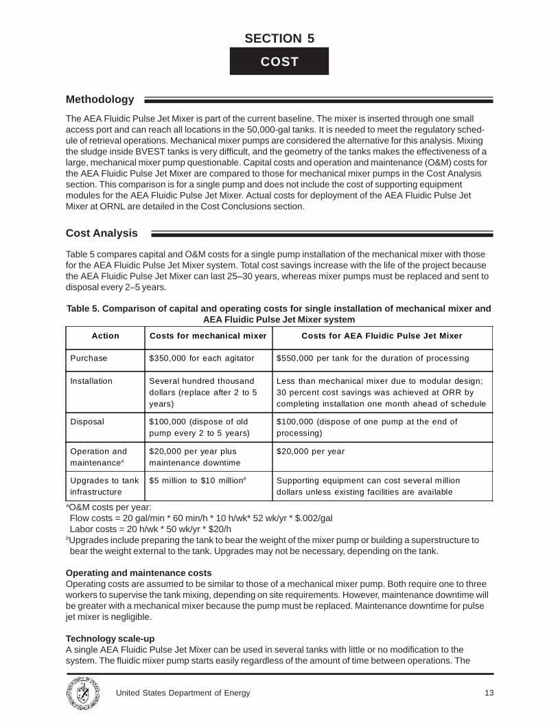
The AEA Fluidic Pulse Jet Mixer is part of the current baseline. The mixer is inserted through one smallaccess port and can reach all locations in the 50,000-gal tanks. It is needed to meet the regulatory sched-ule of retrieval operations. Mechanical mixer pumps are considered the alternative for this analysis. Mixingthe sludge inside BVEST tanks is very difficult, and the geometry of the tanks makes the effectiveness of alarge, mechanical mixer pump questionable. Capital costs and operation and maintenance (O&M) costs forthe AEA Fluidic Pulse Jet Mixer are compared to those for mechanical mixer pumps in the Cost Analysissection. This comparison is for a single pump and does not include the cost of supporting equipmentmodules for the AEA Fluidic Pulse Jet Mixer. Actual costs for deployment of the AEA Fluidic Pulse JetMixer at ORNL are detailed in the Cost Conclusions section.
Table 5 compares capital and O&M costs for a single pump installation of the mechanical mixer with thosefor the AEA Fluidic Pulse Jet Mixer system. Total cost savings increase with the life of the project becausethe AEA Fluidic Pulse Jet Mixer can last 25–30 years, whereas mixer pumps must be replaced and sent todisposal every 2–5 years.
aO&M costs per year:Flow costs = 20 gal/min * 60 min/h * 10 h/wk* 52 wk/yr * $.002/galLabor costs = 20 h/wk * 50 wk/yr * $20/h
bUpgrades include preparing the tank to bear the weight of the mixer pump or building a superstructure tobear the weight external to the tank. Upgrades may not be necessary, depending on the tank.
Operating and maintenance costsOperating costs are assumed to be similar to those of a mechanical mixer pump. Both require one to threeworkers to supervise the tank mixing, depending on site requirements. However, maintenance downtime willbe greater with a mechanical mixer because the pump must be replaced. Maintenance downtime for pulsejet mixer is negligible.
Technology scale-upA single AEA Fluidic Pulse Jet Mixer can be used in several tanks with little or no modification to thesystem. The fluidic mixer pump starts easily regardless of the amount of time between operations. The
Table 5. Comparison of capital and operating costs for single installation of mechanical mixer andAEA Fluidic Pulse Jet Mixer system
Action Costs for mechanical mixer Costs for AEA Fluidic Pulse Jet Mixer
Purchase $350,000 for each agitator $550,000 per tank for the duration of processing
Installation Several hundred thousanddollars (replace after 2 to 5years)
Less than mechanical mixer due to modular design;30 percent cost savings was achieved at ORR bycompleting installation one month ahead of schedule
Disposal $100,000 (dispose of oldpump every 2 to 5 years)
$100,000 (dispose of one pump at the end ofprocessing)
Operation andmaintenancea
$20,000 per year plusmaintenance downtime
$20,000 per year
Upgrades to tankinfrastructure
$5 million to $10 millionb Supporting equipment can cost several milliondollars unless existing facilities are available
14 United States Department of Energy
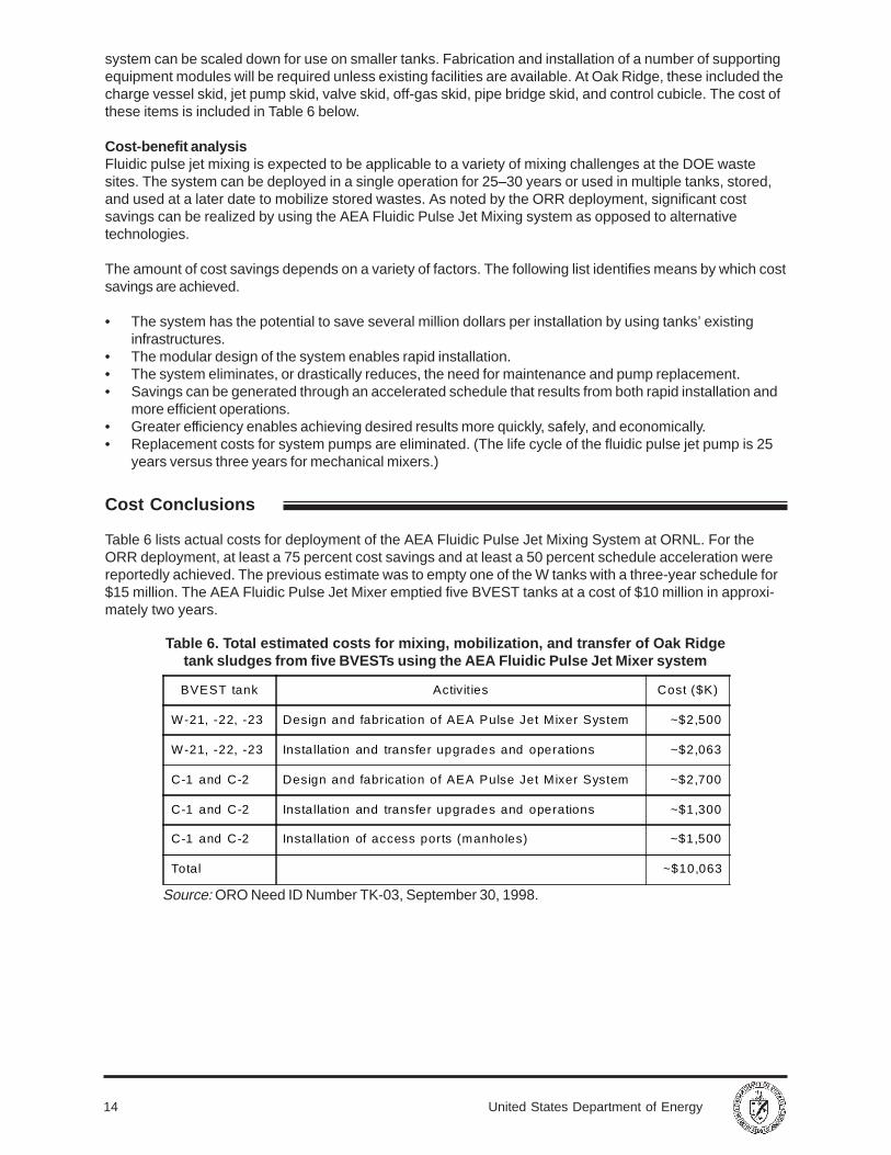
system can be scaled down for use on smaller tanks. Fabrication and installation of a number of supportingequipment modules will be required unless existing facilities are available. At Oak Ridge, these included thecharge vessel skid, jet pump skid, valve skid, off-gas skid, pipe bridge skid, and control cubicle. The cost ofthese items is included in Table 6 below.
Cost-benefit analysisFluidic pulse jet mixing is expected to be applicable to a variety of mixing challenges at the DOE wastesites. The system can be deployed in a single operation for 25–30 years or used in multiple tanks, stored,and used at a later date to mobilize stored wastes. As noted by the ORR deployment, significant costsavings can be realized by using the AEA Fluidic Pulse Jet Mixing system as opposed to alternativetechnologies.
The amount of cost savings depends on a variety of factors. The following list identifies means by which costsavings are achieved.
• The system has the potential to save several million dollars per installation by using tanks’ existinginfrastructures.
• The modular design of the system enables rapid installation.• The system eliminates, or drastically reduces, the need for maintenance and pump replacement.• Savings can be generated through an accelerated schedule that results from both rapid installation and
more efficient operations.• Greater efficiency enables achieving desired results more quickly, safely, and economically.• Replacement costs for system pumps are eliminated. (The life cycle of the fluidic pulse jet pump is 25
years versus three years for mechanical mixers.)
Table 6 lists actual costs for deployment of the AEA Fluidic Pulse Jet Mixing System at ORNL. For theORR deployment, at least a 75 percent cost savings and at least a 50 percent schedule acceleration werereportedly achieved. The previous estimate was to empty one of the W tanks with a three-year schedule for$15 million. The AEA Fluidic Pulse Jet Mixer emptied five BVEST tanks at a cost of $10 million in approxi-mately two years.
Source: ORO Need ID Number TK-03, September 30, 1998.
BVEST tank Activities Cost ($K)
W-21, -22, -23 Design and fabrication of AEA Pulse Jet Mixer System ~$2,500
W-21, -22, -23 Installation and transfer upgrades and operations ~$2,063
C-1 and C-2 Design and fabrication of AEA Pulse Jet Mixer System ~$2,700
C-1 and C-2 Installation and transfer upgrades and operations ~$1,300
C-1 and C-2 Installation of access ports (manholes) ~$1,500
Total ~$10,063
Table 6. Total estimated costs for mixing, mobilization, and transfer of Oak Ridgetank sludges from five BVESTs using the AEA Fluidic Pulse Jet Mixer system
Cost Conclusions
15United States Department of Energy
Regulatory Considerations
SECTION 6
REGULATORY AND POLICY ISSUES
Site-specific regulatory drivers for remediation of tank wastes at ORR are as follows:
• Oak Ridge Federal Facility Agreement and Consent Order (between the U.S. Environmental ProtectionAgency [EPA] Region IV, DOE, and Tennessee Department of the Environment and Conservation)
• Tennessee Department of Environment and Conservation Commissioner’s Order for the Oak RidgeReservation Site Treatment Plan
• DOE Order 5820.2A/435.1 requiring treatment of transuranic waste for disposal at the Waste IsolationPilot Plant
• Comprehensive Environmental Response, Compensation, and Liability Act (CERCLA) of 1980
The AEA Fluidic Pulse Jet Mixer was deployed on active tanks. Application of CERCLA criteria is notrequired at this time but will be when the tanks are closed. Criteria have been met already and are dis-cussed below.
A formal risk management program was applied to this project. Risk management included detailed hazardand risk assessments, studies, and exercises. Potential risks were identified; characterized in terms of theircauses, consequences, and likelihood of occurrence; and quantified by significance of their impact. Riskmanagement actions were established, prioritized, and implemented, including quality assurance andcontrol procedures and protection measures to cover all aspects of the project.
CERCLA EvaluationThis section summarizes how the AEA Fluidic Pulse Jet Mixer addresses the nine CERCLA evaluationcriteria.
1. Overall Protection of Human Health and the Environment
• Radiation exposure to workers is minimized during installation due to the system’s modular designthat allows for quick installation, and use of quick-connect couplings.
• Exposures are mitigated through the use of personal protective equipment, additional temporaryshielding, and personnel training to enable rapid assembly of equipment.
• Remote-controlled operations and low-maintenance minimize radiation exposure to workers duringoperations.
• Increased efficiency reduces exposure risks to human health and the environment.
2. Compliance with Applicable or Relevant and Appropriate Requirements (ARARs)
• The system was designed and deployed according to applicable regulatory requirements.• Project management included monitoring to ensure requirements were met.
3. Long-Term Effectiveness and Permanence
• The jet pump has an operating life of 25 years, compared to the mechanical pump, which has a lifeexpectancy of only three years.
• The system significantly reduces, if not eliminates, the need for maintenance due to the absence ofmoving parts inside a tank.
16 United States Department of Energy
Safety, Risks, Benefits, and Community Reaction
• Implementation can be accomplished faster than with alternative technologies, thus reducing costand risks while increasing efficiency and safety.
• This technology can help accelerate tank remediation and closure schedules.
4. Reduction of Toxicity, Mobility, or Volume Through Treatment
• As tank sludges and liquids are mixed, they enable retrieval of tank wastes, which reduces wastevolume.
• Waste volume is reduced as a result of minimizing secondary waste generation by using existingsupernatant/liquids in the tank for mixing as opposed to adding process water/acid.
• Because the time required to empty tanks is greatly reduced with this technology, empty tanks canbe reused, or if necessary, prepared for closure.
5. Short-Term Effectiveness
• As a result of the lower implementation costs, and tighter schedule, a Pulse Jet Mixer is highlyeffective in the short term.
6. Implementability
• The system’s modular design simplifies installation and operations.• Maintenance is minimal, if required at all.• Worker training and qualification programs and procedures are in place.• A control system exists for remote operation and monitoring of the system.• Safety interlocks and controls are provided.
7. Cost
• Cost data are provided in Section 5.
8. State (Support Agency) Acceptance
• Both the state of Tennessee and EPA are parties of the federal facilities agreement that coversregulatory issues and establishes requirements for management of tanks.
9. Community Acceptance
• DOE-OR holds meetings with the public on a regular basis to discuss and provide a status of theDOE Transuranic Waste Program. Fact sheets providing technology updates are also distributed tothe public.
Secondary Waste StreamThe wastes generated from the AEA Fluidic Pulse Jet Mixer consist of personal protective equipment,contaminated equipment and hardware, plastic sheeting and containers, hydraulic fluids, and structural steelsupport and platforms. These materials must be decontaminated or disposed of as radioactive waste. Thedisposal site must meet Resource Conservation and Recovery Act Land Disposal Requirements.
Information for this section is covered in the previous section, Regulatory Considerations. Key benefits arediscussed in Section 1 of this document under Demonstration Summary.
17United States Department of Energy
Implementation Considerations
SECTION 7
LESSONS LEARNED
Technology Limitations and Need for Future Development
• The system can be used to mix sludges in multiple tanks when cross-connections to nozzles exist.• The modular design of the system allows for quick installation and minimizes radiation exposure to
workers.• Using existing or recycled supernatant can minimize generation of secondary waste.• Use of on-line monitoring instrumentation for continuous measurement of density and solids content of
the slurry could possibly shorten mixing times, reduce operating costs, and provide greater assuranceof adequate mixing.
Parameters and requirements to be considered for applying this technology include the following:
• site-specific conditions• system modifications to accommodate each tank’s infrastructure• characteristics of a tank’s contents• operating environment and needs• protective measures to be implemented for worker safety
The sludge removal at Oak Ridge was limited by the physical characteristics of the sludge and the tankconfiguration.

18 United States Department of Energy
19United States Department of Energy
APPENDIX A
REFERENCES
AEA Technology PLC. 1997. Implementation of formal project risk management on the field demonstrationof fluidic pulse jet mixers: Main report. AEAT/23911020/R/2/Issue 1.
AEA Technology PLC. 1997. Demonstration of the European safety case: Preliminary safety report on theBethel Valley Evaporator Service Tanks pulse jet mixer. AEAT/23911020/R/4/Issue 2.
Bechtel Jacobs. 1998. Deployment of a fluidic pulse jet mixing system for horizontal waste storage tanks atOak Ridge National Laboratory. BJC/OR-82.
Daymo, E. A. 1997. Industrial mixing techniques for Hanford double-shell tanks. PNNL-11725, UC-721.
Kent, T. E., S. A. Taylor, J. W. Moore, J. L. Stellern, and K. B. Billingsly. 1998. Demonstration of fluidicpulse jet mixing for a horizontal waste storage tank. ORNL/TM-13578.
Mullen, O. D. 1998. Jet pump development. FY98 Midyear presentation technical supplement.
Oak Ridge Site Technology Coordination Group. 1998. “Sludge mixing and mobilization,” in the Oak Ridgetechnology needs database. Retrieved June 10, 1999 from the World Wide Web: http://www.em.doe.gov/techneed/tk03.html.
Rinker, M. W., J. A. Bamberger, F. F. Erian, T. A. Eyre, B. K. Hatchell, O. D. Mullen, M. R. Powell,T. J. Samuel, G. A. Whyatt, and J. A. Yount. 1998. EM-50 Tanks Focus Area retrieval process develop-ment and enhancements. PNNL-12015, UC-721.
Tanks Focus Area. 1997. Tanks Focus Area multiyear program plan: FY98–FY00. PNNL-1162.
Tanks Focus Area. 1998. Focus on: Applying international technology to solve U.S. problems.PNNL-SA-30285.

20 United States Department of Energy
21United States Department of Energy
APPENDIX B
ACRONYMS AND ABBREVIATIONS
ARAR applicable or relevant and appropriate requirement
BVEST Bethel Valley Evaporator Service Tanks
CERCLA Comprehensive Environmental Response, Compensation, and Liability Act
DOE U.S. Department of Energy
EPA Environmental Protection Agency
FY fiscal year
O&M operation and maintenanceORNL Oak Ridge National LaboratoryORR Oak Ridge ReservationOST Office of Science and Technology
PVV pump and valve vault
SR Savannah RiverSRS Savannah River Site