Embed Size (px)
Citation preview
department of agricultural engineering
Thusses forFarrn BuildingsGeorge A. Duncan, John N. Walker, George I\,1. Turne r
university of kentucky . college of agriculture . cooperative extension serviceagriculture . home economics . 4h . developmenr
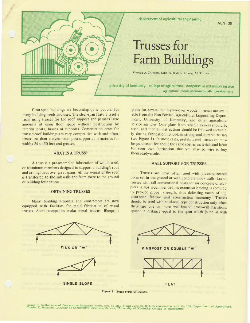
Clear-span buildings are becoming quite popular formany building needs and uses. The clear-span feature resultsfrom using trusses for the roof support and permits largeamounts of open tloor space without obstruction byinterior posts, braces or supports. Construction costs fortrussed-roof buildings are very competit ive with and often-times less than conventional post-supported structures forwidths 24 to 50 feet and sreater.
WHAT IS A TRUSS?
A truss is a pre-assembled fabrication of wood, steel,or aluminum members designed to support a building's roofand ceil ing loads over great spans. All the weight of the roofis transferred to the sidewalls and from there to the ground
or building foundation-
OBTAIMNG TRUSSES
Many building suppliers and contractors are nowequipped with facil i t ies for rapid fabrication of woodtrusses. Some companjes make metal trusses. Blueprint
F I N K O R , , W "
plans for several build-your-own wooden trusses are avail-able from the PIan Service, Agricultural Engineering Depart_ment , Univers i ty of Kentucky, ancl other agr icu l tura lservice agencies. Only plans frorn reliable sources shoulci beused, and then a l l inst ruct ions should be fo l lowed accurate-ly during fabrication to obtain strong and durable trusscs(see Figure l). In rnost cases, prefabricated trusses can nowbe purchased for about the same cost as materials and laborfor your own fabrication, thus you may be wise to buythem ready-made.
WALL SUPPORT FOR TRUSSES
Trusses are most often used with pressure-treatedpoles set in the ground or with concrete block walls. Use oflrusses with tall conventional posts set on concrete or stubpiers is not reconlmended, as extensive bracing is requiredto provide proper strength, thus defeating much of theclear-span feature and construction economv. Trussesshould be used wirh srud-wal l type construct ion only whenthere are one or more well-braced cross-wall partit ionsspaced a distance equal to the span width (such as with
K I N G P O S T O R D O U B L E , . W . .
\l\l\t/tA/I
Figure l: Some types of trusses
S I N G L E S L O P E
I s u e d i n { u r t h e r a n c e o f C o o p c r a t i ! e E _ r t e n s i o n u , o r k ,Charles E. Barnhart , Dircctor of C()operi t t ive Extension
t
acts o f X{ay B and June 30 , 1914,Serv ice , Un ivers i ty o f Kentucky
F L A T
in cooperat ion s ' i th theCol lege of Agricul ture.
I
U.S. Depar tment o f Agr icu l tu re
residential construction) or when there is a "knee-brace"every six to eight feet from the truss to the side-wall, aswith properly-designed animal or poultry facilities.
TYPES OF TRUSSES
There are many types of trusses. Some of the morepopular types are shown in Figure L
CONSTRUCTION MATERJALS
For wooden construction, good quality kiln-dried,dressed lumber, or air-dried planed native lumber isrequired. Standard or construction grade fir, No. I or 2Southern yellow pine, or equivalent grades and species aregenerally specified. A single knot or other wood defect in ajoint or other critical place can seriously weaken a truss.Joint construction methods and materials are also veryimportant.
JOINT CONSTRUCTION METHODS
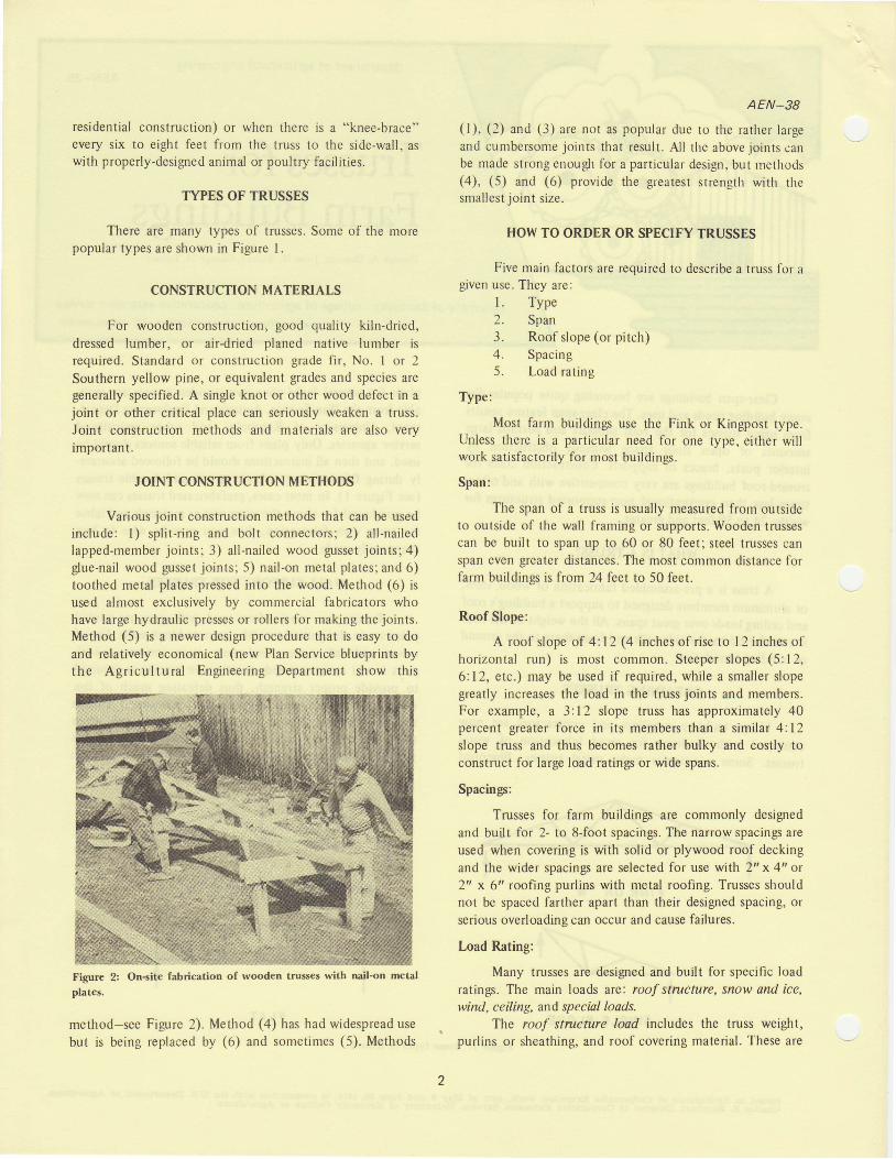
Various joint construction methods that can be usedinclude: l) split-ring and bolt connectors; 2) all-nailedlapped-member joints; 3) all-nailed wood gusset joints;4)glue-nail wood gusset joints; 5) nail-on metal plates; and 6)toothed metal plates pressed into the wood. Method (6) isused almost exclusively by commercial fabricators whohave large hydraulic presses or rollers for making the joints.Method (5) is a newer desigr procedure that is easy to doand relatively economical (new Plan Service blueprints bythe Agricultural Engineering Department show this
Figure 2: On*ite fabrication of wooden trusses with nail-on mctal
plates.
method-see Figure 2). Method (a) has had widespread usebut is being replaced bV (0) and sometimes (5). Methods
AEN_38
(l), (2) and (3) are not as popular due to the rarher largeand cumbersome joints that result. All the above joints canbe made strong enough for a particular design. but rnethods(4), (5) and (6) provide the greatest strengrll with thesmallest joint size.
HOW TO ORDER OR SPECIFY TRUSSES
Five main factors are required to describe a truss for agiven use. They are:
l. Type2. Span3. Roof slope (or pitch)4. Spacing5. Load rating
Type:
Most farm buildings use the Fink or Kingpost type.Unless thcre is a particular need for one type, either wil lwork satisfactorily for most buildings.
Span:
The span of a truss is usually measured from outsideto outside of the wall framing or supports. Wooden trussescan be built to span up to 60 or 80 feet; steel trusses canspan even greater distances. The most common distance forfarm buildings is from 24 feet to 50 feet.
Roof Slope:
A roof slope of 4:12 (4 inches of rise to I 2 inches ofhorizontal run) is most common. Steeper slopes (5:12,6:12, etc-) may be used if required, while a smaller slopegreatly increases the load in the truss joints and members.For example, a 3:12 slope truss has approximately 40percent greater force in its memben than a similar 4:12slope truss and thus becomes rather bulky and costly toconstruct for large load ratings or wide spans.
Spacings:
Trusses for farm buildings are commonly designedand built for 2- to 8-foot spacings. The narrow spacings areused when covering is with solid or plywood roof deckingand the wider spacings are selected for use with 2" x 4" or2" x 6n roofing purlins with metal roofing. Trusses shouldnot be spaced farther apart than their designed spacing, orserious overloading can occur and cause failures.
Load Rating:
Many trusses are designed and built for specific loadratings. The main loads are: roof structure, snow and ice,wirul, ceiling, and special loads.
The roof strucntre /oad includes the truss weight,purlins or sheathing, and roof covering material. These are
often called the "dead loads" since they are a fixed andpermanent part of the roof structure. The dead load fornormal metal or aspha.lt shingle roofs used in agriculturalstructures varies between 5 and l0 pounds per square foot(psf). The actual dead weight can be calculated for anygiven structure system; however, an average value of 7 psfcan generally be used for metal or shingie roofs.
Snow, ice, and v,ind loads vary throughout the yearand are different for different parts of the country. Theseloads are often called "live loads" because they vary withchanging weather conditions. Snow and ice loads are gravityloads and act as downward forces on the roof. Wind forces,however, can cause an uplift on the roof and thus must beconsidered as such in truss design and building construc-Iion. Holding a truss or roof down may be just as citicqlas holding it up.
Selection of the proper l ive load values for a buildingis quite important and realistic judgement should be used.If highly conservative values are selected, the structuralsystem will be overdesigned and wil l be uneconomical. Careshould be used, however, to include all loading of signifi-cance and to select the correct magnitude of loading so thatthe system is not under-designed. Ifuncertainty exists as tothe true nature of the loads which wil l be imposed, it isbetter to make a Oonservative estimate than to risk thedanger of a structural failure.
ln the selection of design l ive loads, the nature orpurpose of the building is also important. For instance, amore conservative selection of Ioad values should be madefor a building where a large number of people are to workthan is necessary for a temporary structure or a structurefor housing low-cost material such as hay. General recom-mendations are that permanent housing should be designedfor severe loads, even though they rnay occur only once in a100 years, when the housing is to be used by the public orwhere the economic consequences of failure would beserious. For buildings occupied by only a f 'ew people, thedesign should be based on 50 years; for l ivestock facil i t ies,crop storages, processing facil i t ies, and machinery storage,
25 years; and for low cost, shorti i fe shelters, l0 years.
Thus, the live loads for these various types of facilities and
the frequency of severe loads should be known and isdiscussed in the following paragraphs.
Snow Loadilzg.' Weather records were analyzed to
determine the probabil ity of various amounts of snowoccurring in several geographical regions. The analysis was
based on the frequency of occurrence of various magni-tudes of snow on the ground. For Kentucky, the following
was reported:
AEN-38
Table l: Probable Snorv Loads for Various Recunence Inten'als.
Recurrence Interval Snon' Load, Lbs. Per Squarc F't.
Years
1 0 05025l 0
Ground
l ,
l 086
Roof
I 1 . 3
t . b6 . 14 .6
This means that once in 100 years a snow depthshould occur which would cause a load on the ground of I 5pounds per square foot. However, within a lO-year period,you would only expect a snow load of 6 pounds per squarefoot. This, however, is not the load irnposed on a building.Since the roof is above ground level, natural wind currentswill cause less snow to fall on the roof than falls on theground, with the actual amount being dependent upon thedryness of the snow. For wet, sticky snow it is recom-mended that designs be based on the assumption that 80percent of the fall ing snow will accumulate on the roof.
Roof slope is also important. The steeper the roof,the smaller the amount of snow which wil l accumulate onthe roof . For roof s lopes of 3:12 or 4:12, which arecommonly used in agricultural structures, an additionalreduction of about f ive percent can be rnade. Thus, theadjusted snow load values which would actually apply tothe roof of a typical building are given in Table I under the"Roof" column.
If a dead load, as previously discussed, is added tothese figures, the design load for snow conditions isobtained. For Kentucky, the design load for even theseverest snow probabil ity would be less than 20 pounds persquare foot. That is, I 1.5 pounds per square foot of snowload, plus 7.0 pounds per square foot dead load. Most plansavailable frorn the University of Kentucky and from otherpublic agencies for agricultural buildings are designed for aminirnum of 20 pounds per square foot, and most aredesigned for 25 to 35 pounds per square foot. Truss plansfor residential use are frequently designed for 35 to 40pounds per square foot. Therefore, if available designs arefollowed, structural failure due to snow Ioading should notbe a problem in Kentucky.
Ice loading sometimes occurs along with snow load-ing, but the maximum load, either alone or in combinationwith snow, is not considered to exceed the pertinent snowloads.
llind Loads: A similar analysis to that described forsnow loads was also made for wind loads. In this case, theprobabil ity of occurrence of various lt igh wind speeds wasdeterrnined. The values given are for a height of 30 feet. Atlower heights a lower wind speed would be observed.Momentary gusts were excluded since buildings can with-
Recurrencelnterval WindVelocity,MPH
Years
Pressure, Lb Per SquareFt., Perpendiculiar to
Wind
stand very short periods of wind pressures. Tornadoes werealso excluded.
Table 2: Probablc High Wind Velocities for Various Recurrence
lntervals.
AEN_38
the most serious problem in Kentucky, the anchoring of theroof system to the foundation to prevent uplift ing nlust beequivalent to the support given to carry the "l ive" snowloatl. Consequently, the attachrnent of the purlins or roofgirts to the rafters or trusses, of the trusses and rafters tothe sidewall or plates, of the sidewall supporting posts tothe foundation, must receive special consideration, whichwe shall discuss later'.
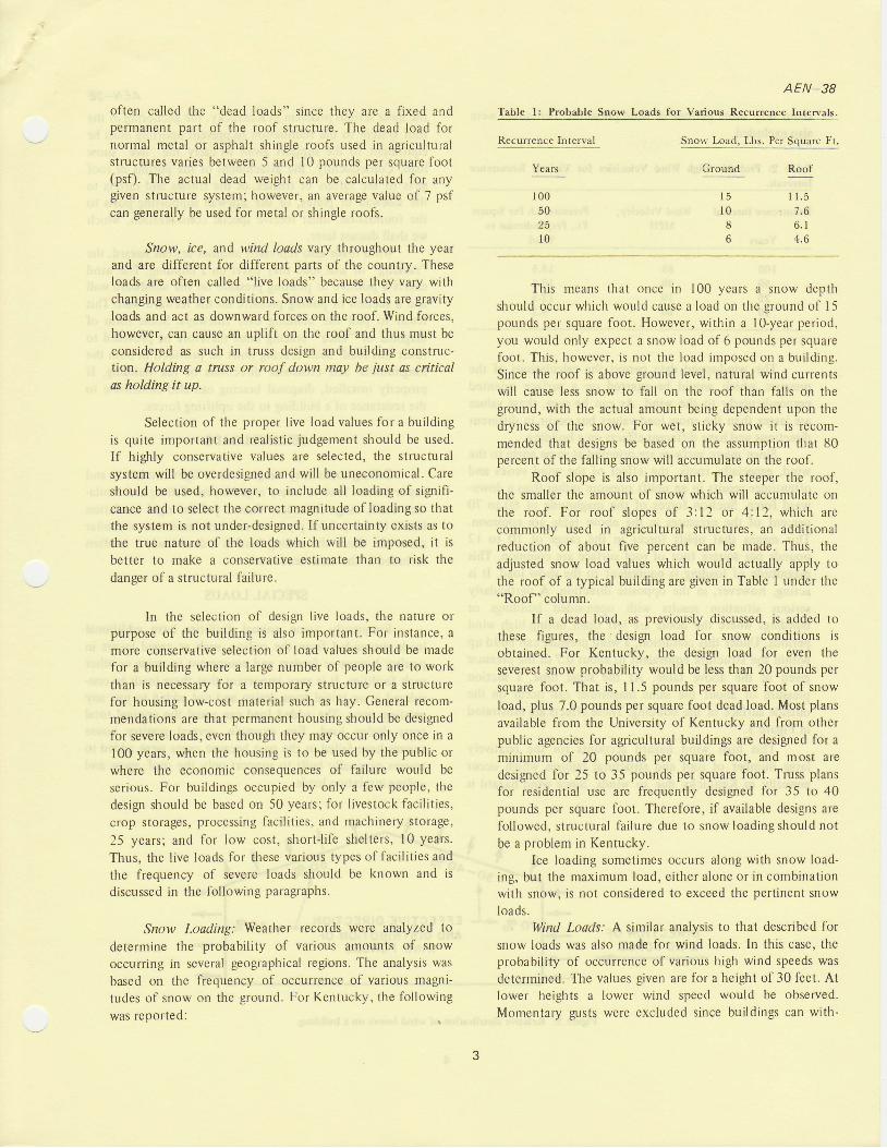
Wind loads also represent another serious hazard. thc"racking" or side load they exert on a building. The windexerts a positive or pushing pressure on the windward walland a suction or pull ing pressure on the leeward wall. Thistends to pull the building over sideways. Some fornr ofdiagonal or "knee" bracing must therefore be provided toresist this load. Such bracing must be provided in both thelongitudinal and crosswise directions of the building. Ifproperly installed, diagonal bracing can also contribute tothe resistance of a building to the uplift ing forces.
CEILING LOADS
Ceiling loads may range from a l ight insulation andvapor barrier load to heavy caged layers. Ceil ing and insula-tion loads range from less than I psf for rigid insulationboard to 2-3 psf for plywood and batt insulation or similarmaterials. Since the ceil ing load is a dead load, it is oftenincluded in the totd dead load.
SPECIAL LOADS
Frequently some animal facilities have additionalloads suspended from the ceiling, such as caged layers inpoultry houses or feeders and equipment in swine or othersuch facilities. It is very important that these loads be con-sidered in an initial truss design and not added to just anyexisting truss. The added load can equal the original totaltruss design load. For example, several poultry housetrusscs have failed in the past because cages were added totrusses originally built to support only the roof, snow andceil ing insulation loads.
85807060
1 0 05025l 0
t 8.516.4t2.59 . 2
The wind-speed data permit the calculations of ihepressure which would be exerted on a surface orientedperpendicularly to the wind. As can be seen, these valuesare larger than the snow load values but occur in differentdirections and have different effects on a building.
Since many surfaces are oriented at some angle to thewind, especially roofs, the effect of the wind varies andoftentimes results in an uplift pressure rather than a down-ward force. Suction forces of the magnitude of 60 to 70perc€nt of the pressures in the above table are common.This means that uplift forces in the range of l0 to 12pounds per square foot of roof surface are common. Thismagnitude of loading is equivalent to the snow load. It isacting, however, in the opposite direction. A particularlyserious situation results with open-sided buildings orbuildings where the doors are left open during high windperiods. Under this condition, a wind pressure can build upwithin the structure equivalent to about 0.7 of the pressuregiven in the above table. At the same time, a srctionpressure of about the same magnitude can occur on theoutside surface of the buildins. These effects are illustratedin Figure 3.
This high wind hazard accounts for the relativelylarge number of roof and structural failures which occurannually in Kentucky due to winds. Since wind hazard is
D I R E C T I O N O FWIND FORCE
lff.ao"to siz\
ro v"J fllE-qILu-E -qllF-glro] \, oo ooAND D ISTRIBUTION OF
WIND FORCES
Figure 3: Relative distribution of wind forces on a building.
Gable type roof, trusses 4' apart,2'r x 4r'purlins
2' apaft, metal roofGable roof, trusses 2 r apart, sheathed with 3 1 4"
boards, l5-pound felt, 210-pound asphaltshingles
Snow and Ice (Kerrtucky, 50 year probability)
lVind (Kentucky, 50 year probability)
Note: Use proper design procedures for
wind loads.
Criling:3/8tr plywood or I /2" fiberboard, vapor
barrier, and insulationRigid insulation board
Caged laycrs, each cage row with cages 2 highand 2 wide, with feed and water trough,litter board.
A summary of approximate loads for truss design andusage in Kentucky is given in Table 3.
Table 3: Summary of Approximate Loads for Truss Design andUsage in Kentucky
TYPE LOAD P.S.F.
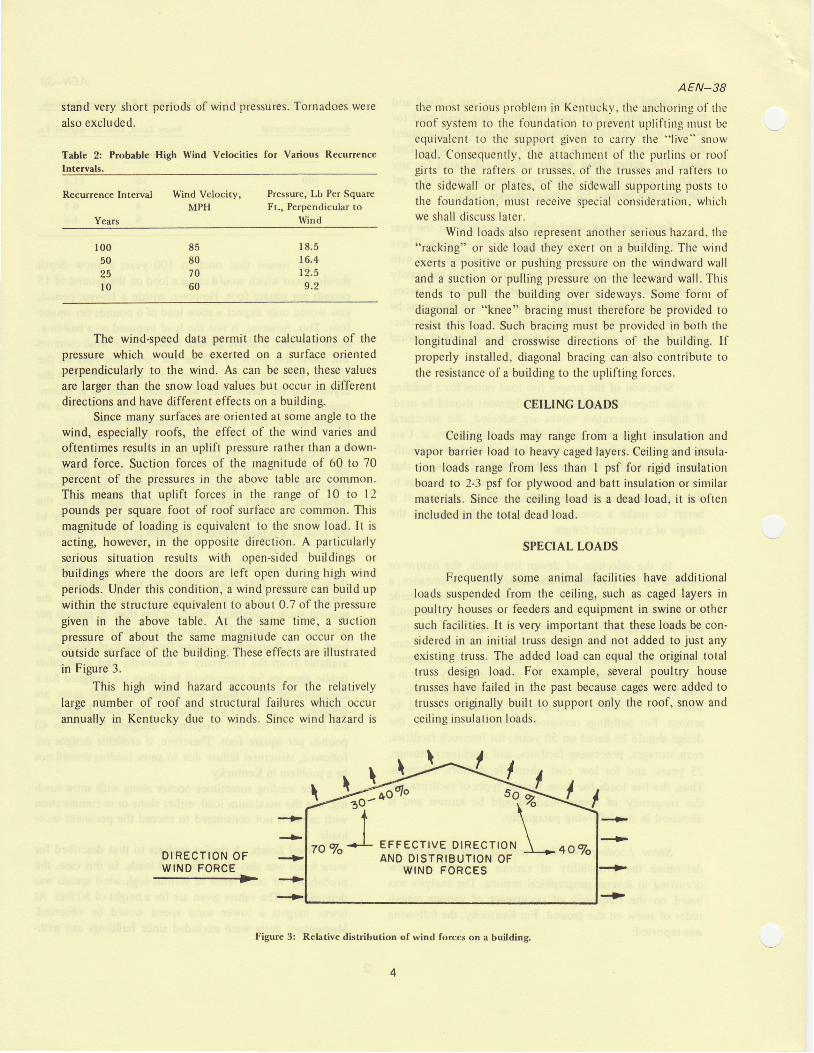
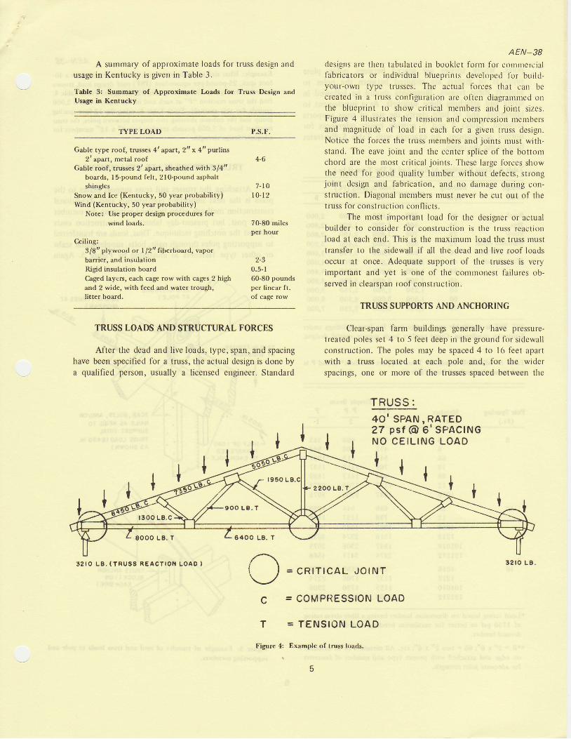
AEN_38designs are then tabulated in booklet form tbr comnlercialfabricators or individual blueprints develcped lbr build-your-own type trusses. The actual forces that can becreated in a tluss configuration are often diagrannted onthe blueprint to show crit ical nleml')ers and joint sizes.Figure 4 i l lustrates the tension and cornpression rnembersand magnitudc of load in each for a given lruss design.Notice thc forces the truss rnembers and joints nlust witlt-stand. The eave joint and the center splice of the bottonlchord are the rnost crit ical joints. These lalge forces showthe need for good quality lunrber without defects, strongjoint design and fabrication, and no danlage during con-struction. Diagonal nleulbers rnust never be cut out of thetruss for construclion conflicts.
The tnost important load for the designer or actualbuilder to consider for construction is the truss reactionload at each end. This is the maximunr load the truss lnusttransfer to the sidewall if all the dead and live roof loadsoccur at once. Adequate support of the trusses is veryimportant and yet is one of thc conrrnotrest failures ob-served in clearspan roof construction.
TRUSS SUPPORTS AND ANCHORING
Clear-span farm buildings generally have pressure-treatcd poles set 4 to 5 feet deep in the ground for sidewallconstruction. The poles may be spaced 4 to 16 feet apartwith a truss located at each pole and, for the widerspacings, one or nrore of the trusses spaced between the
TRUSS :
4-6
7 - l 0l 0 - 1 2
70-80 milesper hour
2-30.5-l60-80 poundsper linear ft.of cage row
TRUSS LOADS AND STRUCTURAL FORCES
After the dead and live loads, type, span, and spacinghave been specified for a truss, the actual design is done bya qualif ied person, usually a l icensed engineer. Standard
8 0 0 0 L B . T 6 4 0 0 L B . T
40 ,SPAN,RATED27 ps t @ 6 'SPACINGNO CEIL ING LOAD
l,>{{, I I
3 2 I O L 8 . ( T R U S S R E A C T I O N L O A D ) 3 2 r O L B .
c
T
= COMPRESSION LOAD
= TENSION LOAD
Figure 4: Example of truss loads.
O = cRtr lcAL JolNr
poles. Where trusses are spaced between poles, platesupports or girders are required between the poles tosupport these trusses. Blueprints should be followed insizing and attaching these supports. As a supplement toblueprints, and to help clarify the size of truss supportsrequired, Tables 4 and 5 provide handy references fornormal applications. An example with Table 5 illustrateshow to use the tables.
Table 4: Truss Reactions At Each End of The Truss (Lbs.)
Truss Spacing (Ft.)
AEN-38
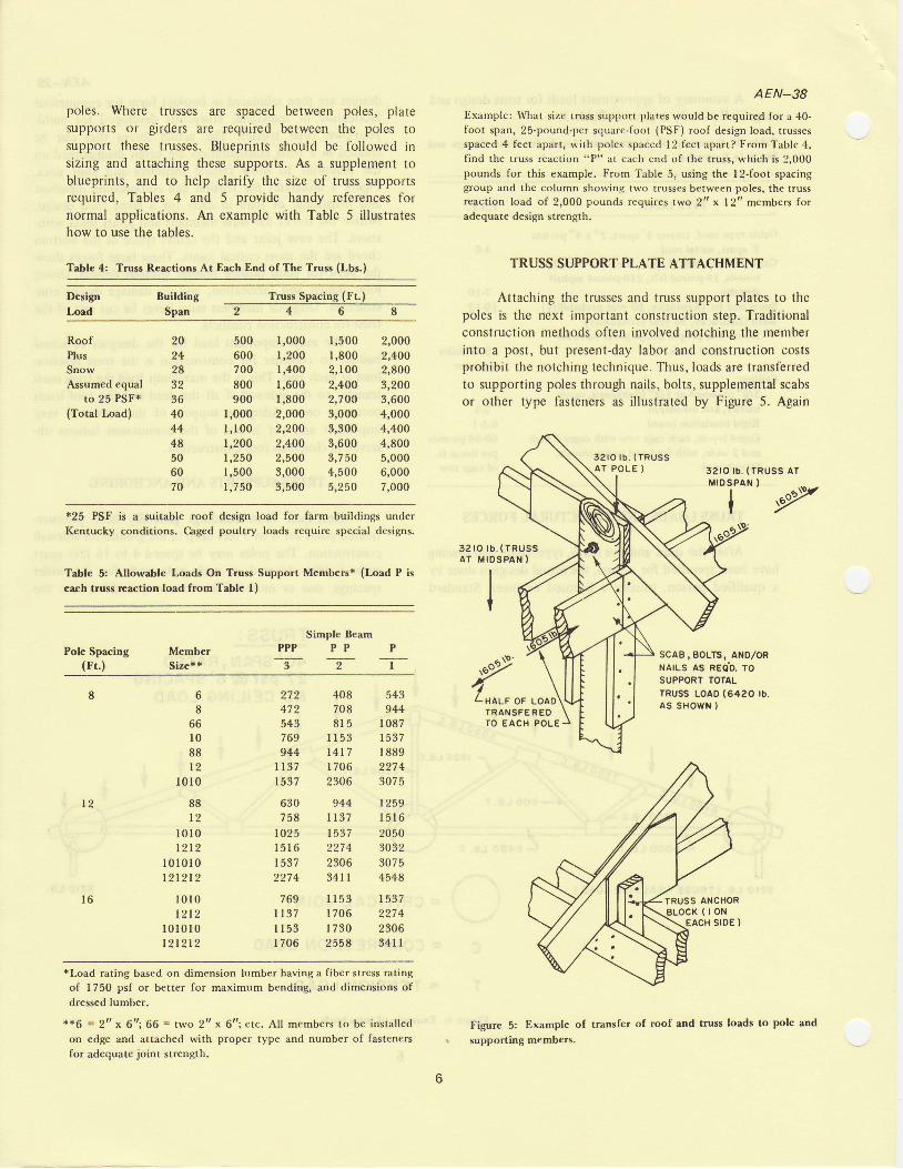
Example: \4rhat size truss support plates would be required {or a 40-foot span, 25-pound-per square-foot (PSF) roof design load, trussesspaced 4 feet apart, with poles spaced l2 feet apart? l'rom Table 4,find the truss reaction "P" at each end of the truss, u'hich is ?,000pounds for this example. From Table 5, using the I 2-foot spacinggroup and the column showing two trusses betwecn poles, the trussreact ion load of 2,000 pounds requires two 2r 'x l2t t members foradequate design strength.
TRUSS SUPPORT PLATE ATTACHMENT
Attaching the trusses and truss support plates to thepoles is the next important construction step. Traditionalconstruction methods often involved notching the nremberinto a post, but present-day labor and construction costsprohibit the notching technique. Thus, loads are transferredto supporting poles through nails, bolts, supplemental scabsor other type fasteners as illustrated by Figure 5. Again
32 tO t b . (TRUSS A r
Dcsign
Load
Building
Span
RoofPlusSnowAssumed equal
to 25 PSF*(Total Load)
500 1,000600 1,200700 l,400800 1,600900 1,800
I,000 2,000I,100 2,2001,200 2,400t,250 2,5001,500 3,000r,7 50 3,500
1,500 2,0001,800 2,4002,100 2 ,8002,400 3,2002,700 3,6003,000 4,0003,300 4,4003,600 4,8003,750 5,0004,500 6,0005,250 7,000
2024283236404448506070 M I D S P A N }
I*25 PSF is a suitable roof design load for farm buildings underKentucky conditions. Caged poultry loads require special designs.
Table 5: Allowable Loads On Truss Support Members* (Load P is
each truss rcaction load from Table l)
3 2 r O t b . ( T R U S SAT MIDSPAN )
Pole Spacing(rt.)
MemberSize**
Simple BeamP P P P P P
3 2 1 ,PZro* o, .ooot
SCAB,BOLTS, AND/ORNAILS AS REOb. TOSUPPORT TOTALTRUSS LOAo (6420 rb.as sHowN )
*Load rating based on dimension lumber having a fiber stress ratingof 1750 psf or better for maximum bending, and dimensions of
dressed lumber.
*+6 = 2rt x 6t'; 66 = two 2tt x 6tt; etc. All members to be installed
on edge and attachcd with proper type and number of fasteners
for adequate joint strengh,
T R A N S F E R E OTO EACH POLE
Figure 5: Example of transfer of roof and truss loads to pole and
supporting members.
68
66l 088t 2
l 0 l 0
88r 2
l 0 l 0t2t2
1 0 1 0 1 0l212l2
l 0 l 0t2t2
l 0 l 0 l 012t2t2
272 408 543472 708 944543 81 5 1087769 I 153 t537944 l4t7 I 889
t t37 1706 2274t537 2306 3075
630 944 1259758 t r37 1516
ro25 1537 20501516 2274 3032t537 2306 30752274 34 l l 45+8
769 I 153 1537t t37 1706 2274l 153 I 730 2306I 706 2558 341 I
AEN_38
2tt lumberattached toround orsquarepressure
treatedpoles.
blueprints should specify these joint construction details,but Table 6 is listed as a reference for typical f'astenerdesign loads and estimating joint strengths.
Table 6: Dcsign Loads of Selected Nails and Bolts for Pole BuildingConstruction.
TypeJoint Design Load per Fastener in l,atenl Loading (Lb.)Nails* Bolts**
Size Load Size Single Shear Double Shear
l 6d 130
40d 220
60d 277 9 7 0
*Pertains to ring-shank or screw-shank nails only. Smooth-shankspike nails are not recommended in pressure treated wood. If used,reduce load by one-third to one-half.
**Single shear is the condition where I bolt is through 2 members,each being pulled in opposite directions. Double Shear is where Ibolt is through 3 members with the center member being pulledopposite to the outer two.
In the example of Figure 5 where the truss loads aretransferred to each pole, the plate-to-pole joint mustsupport a total of 6,420 pounds. From Table 6 the numberof 40d nails required to safely transfer this load is twenty-nine (6420 + 220= 29). Other fasteners could also be used.(How many pole barn joints have you seen with about one-third or one-half this number of nails? Such under-sizedjoints seriously affect the strength and safety of thestructure.) Longitudinal bracing as discussed can helpsupport this load. Other techniques are also frequentlyused.
Some commercial pole barn builders use 7', 8', or 9tpole spacing and put a truss only at each pole. The truss-to-pole fastening must still have adequate strength as deter-mined above.
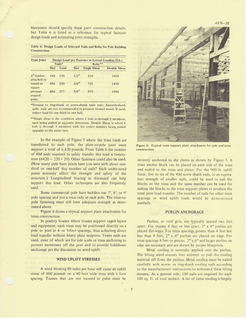
Figure 6 shows a typical support plate attachment fortruss construction.
In poultry houses where lrusses support caged layersand equipment, each truss may be positioned directly on apole or post at 4- or S-foot spacings, thus achieving directload transfer without heavy plate supports. Fewer nails areused, most of which are for side scabs or truss anchoring toprevent movement off the post and to provide holddownanchorage per the discussion on wind uplift.
WIND I.JPIIFT STRESSES
A wind blowing 80 miles per hour wil l cause an upliftstress of 900 pounds on a 40 foot wide truss with 6 footspacing. Trusses that are not located at poles must be
Figure 6: Typical truss support plate attachm€nt for pole and trussconstruction.
securely anchored to the plates as shown by Figure 5. Atruss anchor block can be placed on each side of the trussand nailed to the truss and plates. For the 900 lb. upliftforce, f ive to six of the 40d screw shank nails, or an equiva-lent strength of smaller nails, could be used to nail theblocks to the truss and the sarne number can be used fornail ing the blocks to the truss support plates to producd thetotal joint load transfer. The number of nails for other trussspacings or wind upl i f t loads would be determinedsimilarly.
PTJRLIN ANCHORAGE
Purlins, or roof girts, are typically spaced two fectapart. For trusses 4 feet or less aparl, 2' x 4ttpurlins areplaced flat-ways. For truss spacings greater than 4 fcet butless than 8 feet , 2" x 4 'pur l ins are p laced on edge. Fort russ spacings 8 feet or greater , 1 'x 6 'and larger pur l ins onedge are necessary and are shown by proper blueprints.
Metal roofing is normally applied over the purlins.The lift ing wind stresses first attempt to pull the roofingmaterial off from the purlins. Metal roofing must be nailedcarefully with screw- or ring-shank roofing nails accordingto the manufacturers' instructions to withstand these lift ingstresses. As a general rule, 100 nails are required for each100 sq. ft. of roof surface. A lot of loose roofing is largely
| 12"
518"
314"
5 1 0
725
I 020
I 450
I 940
due to improper and inadequate nail ing rather than poorroofing material.
Asuming the roofing is attached securely to the roofpurlins, then the purlins must withstand and transfer thelifting wind stresses to the truss upper chords. The attach-ment of roof purlins to the trusses can be critically weakjoints in the roof frame. For the previous truss example, an80 mile per hour wind causes 90 pounds of uplift for eachjoint between a purlin and the truss upper chord. The with-drawal resistance of l6d screw-shank nails is approximately75 pounds each (5Vo increase above common spikes), thusat least 2 would be required perjoint. This is possible for 2"x 4"'s flat-ways, but, on edge, the situation is different.Forty or 60d nails would be required to drive through theedge of a 2" x 4" and penetrate the top chord. 60d screwstrank nails hold approximately 105 pounds each, thus onewould equal the 90 pounds required. Since "toe-nailing" isan unreliable joint and strength data are not available, toe-nailed joints would be unpredictable and are to be avoidedifat all possible.
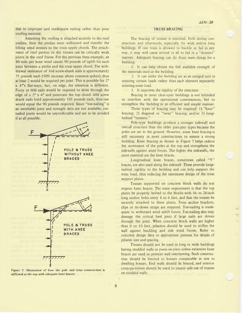
Figure 7: Illustration of how the pole and truss construction is
stiffcned at the top with adequate knee braces.
AEN_38
TRUSS BRACING
The bracing of tnrsses is esscnlial. both during con-struction and aftcrwards, especially for wide and/or longbuildings. If one truss is allowed to bucklc or fail in anyway, it may well cause several or all to lail in a "donrino"
manner. Adequate bracing can do three main things for abuilding:
l. It can help obtain the full available strength ofthe materials used in the building.
2. lt can rnake the building act as an integral unit it lresisting certain loads rather than each element separatelyresisting some load.
3. It improves the rigidity of the structure.Bracing in most clear-span buildings is not intended
to interfere with the operational conveniences, but tostrengthen the building in an efficient and sinrple manner.
Three types of bracing may be required: l) "knee"bracing; 2) diagonal or "sway" bracing; and/or 3) lon$-tudinal "runners."
Pole{ype buildings produce a stronger sidewall andoverall structure than the older post-pier types because thepoles are set in the ground. However, some knee bracing isstill necessary in most constructions to ensure a strongbuilding. Knee bracing as shown in Figure 7 helps reducethe movement of the poles at the top and strengthens thesidewalls against wind forces. The higher the sidewalls, themore essential are the knee braces.
Longitudinal knee braces, sometimes called "Y"braces, are also used along the sidewall. These provide longi-tudinal rigidity to the building and can help support thetruss load, thus reducing the maximum design of the trusssupport plates.
Trusses supported on concrete block walls do notrequire knee braces. The main requirement is that the topplates be properly bolted to the blocks with 16- to 24-inchlong anchor bolts every 4 to 6 feet, and that the trusses besecurely attached to these plates. Truss anchor brackets,clips or tie-down straps are required. Toe-nailing is inade-quate to withstand wind uplift forces. Toe-nailing also maydamage the critical heel joint if large nails are driventhrough the joint. When concrete block walls are higherthan 8 to l0 feet, pilasters should be used to stiffen thewall against buckling and side wind forces. Refer toconcrete design data or appropriate persons for details ofpilaster size and spacing.
Trusses should not be used in long or wide buildingshaving studded walls or posts-on-piers unles extensive kneebraces are used to prevent wall overturning. Such construc-tion should be l imited to houses comparable in size todwelling houses. End walls should be braced, and interiorcross-partitions should be used to ensure safe use oftrusseson studded walls.
P O L E A T R U S SW I T H O U T K N E EB R A C E S
P O L E A T R U S SW I T H K N E EB R A C E S
D I A G O N A L
" x " B R A c T N GC E N T E R O F T H E
AEN_38
" swAY " oRD O W N T H E
T R U S S E SL O N G I T U D I N A L R U N N E R S
ON TOP OF BOTTOM CHORDS( 2 o r 3 E Q U A L L Y S P A C E D ,
N O T N E C E S S A R Y I F R I G I DC E I L I N G U S E D )
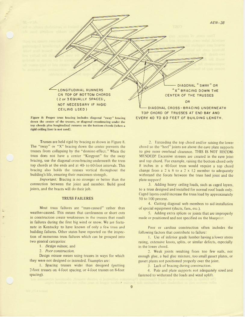
Figure 8: Proper truss bracing includes diagonal "sway" bracingdown the center of the trusses, or diagonal crossbracing under thetop chords plus longitudinal runners on the bottom chords (when arigid ceiling liner is not used).
Trusses are held rigid by bracing as shown in Figure 8.The "sway" or "X" bracing down the center prevents thetrusses from collapsing by the "domino effect." When thetruss does not have a center "Kingpost" tbr the swaybracing, use the diagonal cross-bracing underneath the trusstop chords at the ends and at 40- to 60-foot intervals. Thisbracing also holds the trusses vertical throughout thebuilding's l i fe, ensuring their maximum strength.
Important: Bracing is no stronger or better than theconnection between the joint and member. Build goodjoints, and the braces wil l do their job.
TRUSS FAILURES
Most truss failures are "man-caused" rather thanweather-caused. This means that carelessness or short cutsin construction create weaknesses in the trusses that resultin failures during the first big wind or snow. We are fortu-nate in Kentucky to have known of only a few truss andbuilding failures. Other states have reported on the inspec-tion of numerous truss failures which can be grouped intotwo general categories:
1. Design misuse, and2. Poor construction.Desiglt misuse means using trusses in ways for which
they were not designed or intended. Examples are:l. Spacing trusses wider than designed (putting
2-foot trusses on 4-foot spacing, or 4-foot trusses on 8-footspacing).
D I A G O N A L C R O S S - B R A C I N G U N D E R N E A T H
TOP CHORD OF TRUSSES AT END BAY ANDE V E R Y 4 0 T O 6 O F E E T O F B U I L D I N G L E N G T H .
2. Extending the top chord and/or raising the lowerchord so the "heel"joints are above the eave plate supportsto give more overhead clearance. THIS IS NOT RECOM-MENDED! Excessive stresses are created in the eave jointand top chord. For example, raising the bottom chord only8 inches in a 40-foot truss would require a top chordchange from a 2 x 8 to a 2 x 12 member to adequatelywithstand the forces between the truss heel joint and theplate support!
3. Adding heavy ceil ing loads, such as caged layers,to a truss designed and installed for normal roof loads only.Caged layers could increase the truss load by approximately50 to 100 percent.
4. Cutting diagonal web members to aid installationof special equipment (ducts, fans, etc.).
5. Adding extra splices or joints that are improperlymade or positioned and not specified on the blueprint.
Poor or careless construction often includes thefollowing factors that contribute to failure:
l. Use of inferior grade lumber having a lower stressrating, extensive knots, splits, or similar defects, especiallyin the lower chord.
2. Weak joints resulting from too few nails, notenough glue, a bad glue mixture, too small gusset plates, orgusset plates not positioned properly over the joint.
3. Lack of bracing during construction.4. Pole and plate supports not adequately sized and
fastened to withstand the loads and wind uplift.
O R
cosr
Truss costs, of course, vary according to location,material, labor costs, quantity, and delivery distance. Checkseveral area suppliers for your needs and delivery schedule.Material costs for build-your-own types are approximatelytwo-thirds the prefabricated cost, but are probably notworth the difference after considering labor costs and jigrequirements for good fabrication results. Build-your.owntrusses may be feasible in locations where the availability of
AEN_38prefabricated tnrsses is limited or particularly costly. or forspecial trusses that are not readily available fronr thefabricator.
Blueprints for several build-your-own trusses are avail-able frorn the Plan Service of the Agricultural EngineeringDepartment at a small charge per plan. Several fann build-ing blueprints include the truss plan with the facility andare designed for the convenience of thc person in decidingwhether to buy or build the trusses and to help ensure theproper type if buying. Also, information on erection ofpole-frame, clear-span bu il dings is available.
Tlle Collcge ol Agriculture is an Eqwl Opportunitg Otganization autlndzed tn prorsiile research, educational inlormatbr andotler senices onlg to iniltoiduals anil institufians thot fimcrlolt isithout rcgard, to race, colan, sex or national origin,
Issued 4-75, 5M