Embed Size (px)
DESCRIPTION
Aermec technica manual
Citation preview

FAN COIL
FCX
TECHNICAL MANUAL
������������� ����������
IFCXTY0806
6191101_00Replace : 64560.41_01 / 0308
3
Ital
iano
4 5 6 7 8 10 11 12 16 17 25 27Potenza termica resa BV (1R) 28 30 32 33 34 35 37 38 53 54 58 74
DECLARATION OF CONFORMITYCarriage • Safety symbolImportant informationDescription • VersionsMain components• Component descriptionSelectionSystem configurationTechnical dataOperating limitsDelivery cooling capacityHeating power input (3R)Heating power input ( (4R)
Cooling power yield (direct expansion)Hanging version available static pressureBattery pressure dropFattori di correzione nel funzionamento with glycol waterSound power and sound pressureSound power level delle versioni pensili canalizzateAccessoriesUnit installation • Electrical connectionsDimensionsWiring diagramTrouble shooting • Maintenance
INDEX
Store the manuals in a dry location to avoid deterioration, asthey must be kept for at least 10 years for any future reference.All the information in this manual must be carefully read andunderstood. Pay particular attention to the operating standardswith “DANGER” or “WARNING” signals as failure tocomply with them can cause damage to the machine and/orpersons or objects.If any malfunctions are not included in this manual, contactthe local After-sales Service immediately.The apparatus must be installed in such a way that maintenan-ce and/or repair operations are possible.The apparatus's warranty does not in any case cover costs due
to automatic ladders, scaffolding or other lifting systems neces-sary for carrying out repairs under guarantee.Normal wear of components and filter is not covered by the warranty.AERMEC S.p.A. declines all responsibility for any damage whatsoevercaused by improper use of the machine, and a partialor superficial acquaintance with the information contained inthis manual.
The number of pages in this manual is: 76.
REMARKS
5
Ital
iano
Engl
ish
Deu
tsch
eEs
paño
lFr
ança
is
5
����
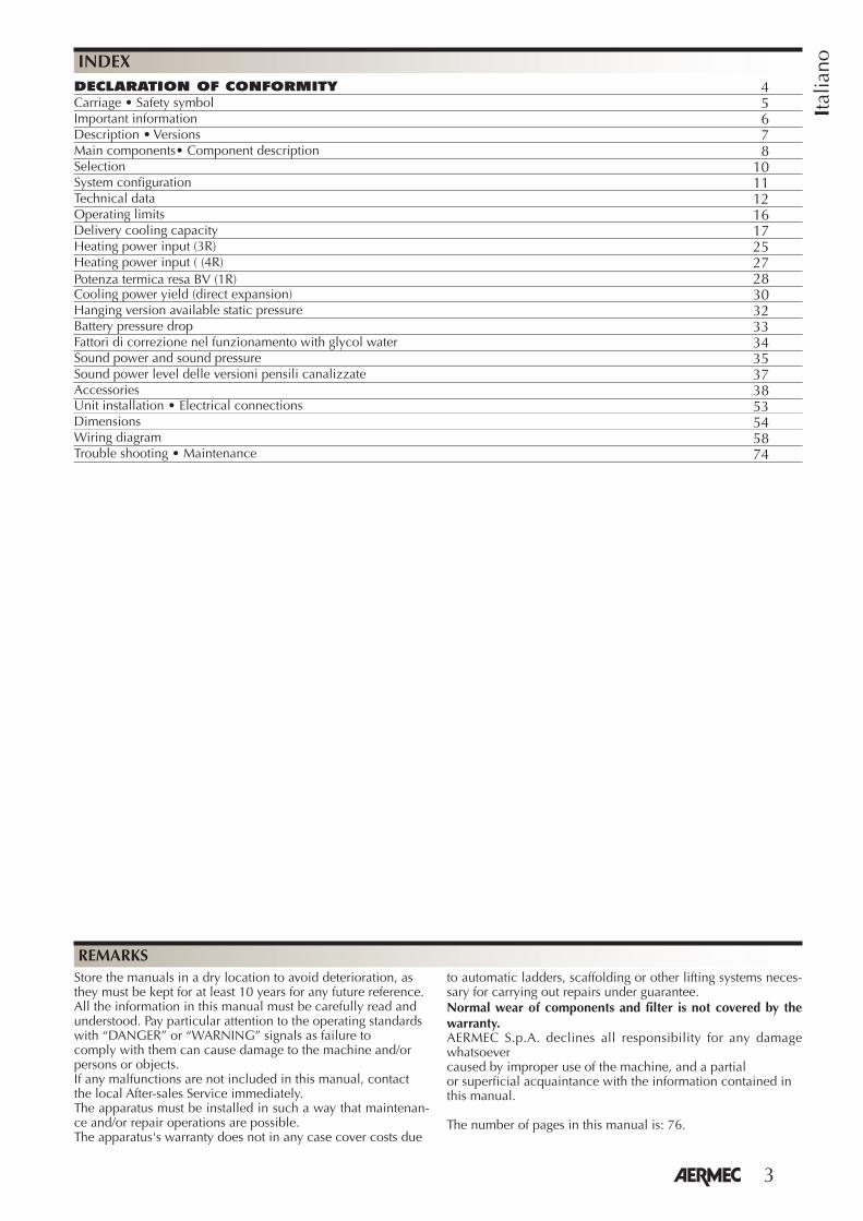
NON bagnare • Do NOT wetCRAINT l’humidité • Vor Nässe schützen
NO mojar
NON lasciare gli imballi sciolti durante il trasporto.Do NOT leave loose packages during transport.ATTACHER les emballages pendant le transport.
Die Verpackungen nicht ungesichert transportieren.NO lleve las cajas sueltas durante el transporte.
Sovrapponibilità: controllare sull’imballo la posizione della freccia per conoscere il numero di macchine impilabili.
Stacking: control the packing for the arrow position to know the num-ber of machines that can be stacked.
Empilement: vérifier sur l’emballage la position de la flèche pour con-naître le nombre d’appareils pouvant être empilés.
Stapelung: Anhand der Position des Pfeiles an der Verpackung kontrol-lieren, wieviele Geräte stapelbar sind.
Apilamiento: observe en el embalaje la posición de la flecha para saber cuántos equipos pueden apilarse.
NON calpestare • Do NOT trampleNE PAS marcher sur cet emballage • Nicht betreten
NO pisar
NON trasportare la macchina da soli se il suo peso supera i 35 Kg.DO NOT handle the machine alone if its weight is over 35 Kg.
NE PAS transporter tout seul l’appareil si son poids dépasse 35 Kg.Das Gerät NICHT alleine tragen, wenn sein Gewicht 35 Kg überschreitet.
NO maneje los equipos en solitario si pesan más de 35 kg.
Pericolo: Pericolo: Pericolo!!! Tensione Organi in movimento
Danger: Danger: Danger!!! Power supply Movings parts
Danger: Danger: Danger!!! Tension Organes en mouvement
Gefahr ! Gefahr ! Gefahr!!! Spannung Rotierende Teile
Peligro: Peligro: Peligro!!! Tensión Elementos en movimiento
TRASPORTO • CARRIAGE • TRANSPORT • TRANSPORT • TRANSPORTE
SIMBOLI DI SICUREZZA • SAFETY SYMBOL • SIMBOLES DE SECURITE SICHERHEITSSYMBOLE • SÍMBOLOS DE SEGURIDAD
6
Engl
ish
WARNING: The fancoil is connected to the power supply and a water circuit. Operations performed by persons withoutthe required technical skills can lead to personal injury to the operator or damage to the unit and surrounding objects.DANGER: never switch the appliance on without having re/mounted the fan coil casing.The ultra-violet radiation emitted from the bulbs inside is dangerous and can cause conjunctivitis, burns and dermatitis.The device has safety micro switches that prevent functioning if the casing and filter are missing.DANGER: do not tamper with the micro switches as this would make functioning of the fan coil unsafe..
FUNCTIONING ANOMALIESIn the case of functioning anomalies, remove the voltage from the unit and then re-apply it and re-start the appliance. If the problem persists, call the area after-sales service immediately.
ONLY POWER THE FAN COIL USING 230 VOLT, SINGLE-PHASE, 50 HzThe fan coil may undergo permanent damage if different electric power supplies are used.
DO NOT PULL THE ELECTRIC CABLEIt is very dangerous to pull, step on, crush or fix the electric power supply cable using nails or staples.The damaged cable can cause short circuits and injury to persons.
DO NOT INTRODUCE OBJECTS INTO AIR VENTSDo not introduce any type of object into the air outlet slots.
This could cause injury to persons or damage the fan.
NEVER USE THE FANCOIL FOR APPLICATIONS FOR WHICH IT WAS NOT DESIGNEDDo not use the fancoil in husbandry applications (e.g. incubation).
AIR THE ROOMPeriodically air the room in which the fancoil has been installed; this is particularly important if the room is occupied by many people, or if gas appliances or sources of odours are present.
C O R R E C T L Y A D J U S T T H E TEMPERATURERoom temperature should be regulated to ensure maximum comfort to persons present, particularly in the case of theelderly, infants and invalids. Prevent temperature fluctuations between indoors and outdoors greater than 7 °C during summer.Note that very low temperatures during summer will lead to greater electricity consumption.
ORIENT AIR FLOW CORRECTLYAir delivered by the fancoil should not be oriented directly at people; even if air temperature is greater than room temperature, it can cause a cold sensation and consequently discomfort.
DO NOT USE HOT WATERWhen cleaning the indoor unit, use rags or soft sponges soaked in warm water (no higher than 40°C).Do not use chemical products or sol-vents to clean any part of the fancoil.Do not splash water on interior or exte-rior surfaces of the fancoil; danger of short circuit.).
PERIODICALLY CLEAN THE FILTERFrequent cleaning of the filter will ensure more efficient unit operation.Check whether the filter requires cle-aning; if it is particularly dirty, clean it more often.Clean the filter frequently. Use a vacuum cleaner to remove built up dust.After cleaning and drying the filter, fit it on the fancoil by following the removal procedure in reverse order.The normal wear of the germicidal lamp and of the filter are not covered by war-ranty.
SPECIAL CLEANINGThe removable drip tray and fan volute ensure thorough cleaning of the unit (by specifically trained personnel), essen-tial for installations in venues subject to crowding or in those with special hygie-ne requirements.
IT IS NORMALDuring cooling, water vapour may be present in the air delivery of the fan coil.In the heating function it might be possible to hear a slight hiss around the fan coil. Sometimes the fan coil might give off unpleasant smells due to the accumulation of dirt in the air of the environment (especially if the room is not ventilated regularly, clean the filter more often).During the operation, there could be noises and creaks inside the device, due to the various heat expansions of the elements (plastic and metallic), but this does not indicate any malfunctioning and does not cause damage to the unit unless the maximum input water temperature is exceeded.
IMPORTANT MAINTENANCE INFORMATION
7
Engl
ish
FCX - - FAN COIL
The fan coil units treat room air during summer and winter seaqsons.
The FCX fan coi l concentrates high technological and functional characteristics that make it the ideal climate control unit for all types of rooms. The supply of climate controlled air is immediate and distr ibuted throughout the room;; FCX generates heat if included in a heating system with boiler or heat pump but may also be
used in summer as an air conditioner if the heating system has a water chiller..
The removable drip tray and fan volute ensure thoroug cleaning of the unit essential for installations in venues subject to crowding or in those with special hygiene requirements.
The quietness of the new centrifugal fan assembly is such that at normal speed of use you cannot hear when the FCX cuts in.
The FCX fan coil has been designed to meet all system requirements thanks to its extensive range of accessories.
The AERMEC fan coil versions without control panels can be combined to an AERDOMUS central control unit.
Full respect for accident prevention regulations
Congratulations on your purchase of the Aermec FCX fan coil.Made with materials of superior quality in strict compliance with safety regulations, the "FCX " is easy to use andwill have a long life.
VERSION
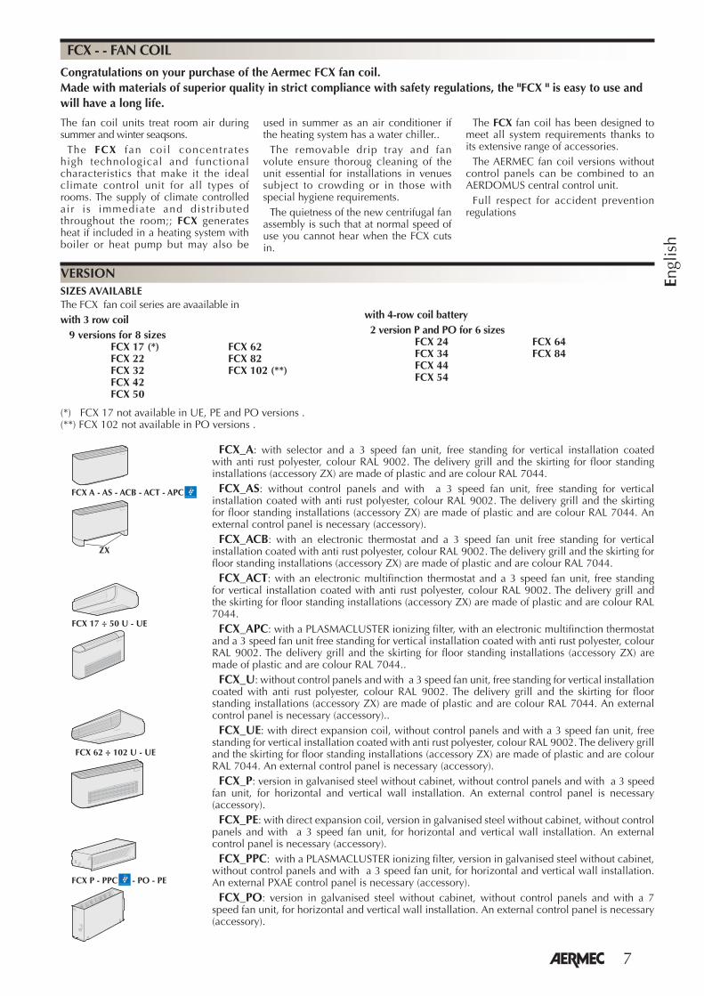
FCX_A: with selector and a 3 speed fan unit, free standing for vertical installation coated with anti rust polyester, colour RAL 9002. The delivery grill and the skirting for floor standing installations (accessory ZX) are made of plastic and are colour RAL 7044.
FCX_AS: without control panels and with a 3 speed fan unit, free standing for vertical installation coated with anti rust polyester, colour RAL 9002. The delivery grill and the skirting for floor standing installations (accessory ZX) are made of plastic and are colour RAL 7044. An external control panel is necessary (accessory).
FCX_ACB: with an electronic thermostat and a 3 speed fan unit free standing for vertical installation coated with anti rust polyester, colour RAL 9002. The delivery grill and the skirting for floor standing installations (accessory ZX) are made of plastic and are colour RAL 7044.
FCX_ACT: with an electronic multifinction thermostat and a 3 speed fan unit, free standing for vertical installation coated with anti rust polyester, colour RAL 9002. The delivery grill and the skirting for floor standing installations (accessory ZX) are made of plastic and are colour RAL 7044.
FCX_APC: with a PLASMACLUSTER ionizing filter, with an electronic multifinction thermostat and a 3 speed fan unit free standing for vertical installation coated with anti rust polyester, colour RAL 9002. The delivery grill and the skirting for floor standing installations (accessory ZX) are made of plastic and are colour RAL 7044..
FCX_U: without control panels and with a 3 speed fan unit, free standing for vertical installation coated with anti rust polyester, colour RAL 9002. The delivery grill and the skirting for floor standing installations (accessory ZX) are made of plastic and are colour RAL 7044. An external control panel is necessary (accessory)..
FCX_UE: with direct expansion coil, without control panels and with a 3 speed fan unit, free standing for vertical installation coated with anti rust polyester, colour RAL 9002. The delivery grill and the skirting for floor standing installations (accessory ZX) are made of plastic and are colour RAL 7044. An external control panel is necessary (accessory).
FCX_P: version in galvanised steel without cabinet, without control panels and with a 3 speed fan unit, for horizontal and vertical wall installation. An external control panel is necessary (accessory).
FCX_PE: with direct expansion coil, version in galvanised steel without cabinet, without control panels and with a 3 speed fan unit, for horizontal and vertical wall installation. An external control panel is necessary (accessory).
FCX_PPC: with a PLASMACLUSTER ionizing filter, version in galvanised steel without cabinet, without control panels and with a 3 speed fan unit, for horizontal and vertical wall installation. An external PXAE control panel is necessary (accessory).
FCX_PO: version in galvanised steel without cabinet, without control panels and with a 7 speed fan unit, for horizontal and vertical wall installation. An external control panel is necessary (accessory).
SIZES AVAILABLEThe FCX fan coil series are avaailable in with 3 row coil 9 versions for 8 sizes FCX 17 (*) FCX 62 FCX 22 FCX 82 FCX 32 FCX 102 (**) FCX 42 FCX 50
(*) FCX 17 not available in UE, PE and PO versions .(**) FCX 102 not available in PO versions .
with 4-row coil battery 2 version P and PO for 6 sizes FCX 24 FCX 64 FCX 34 FCX 84 FCX 44 FCX 54
��
��������
������������������
�����������
������������
8
Engl
ish
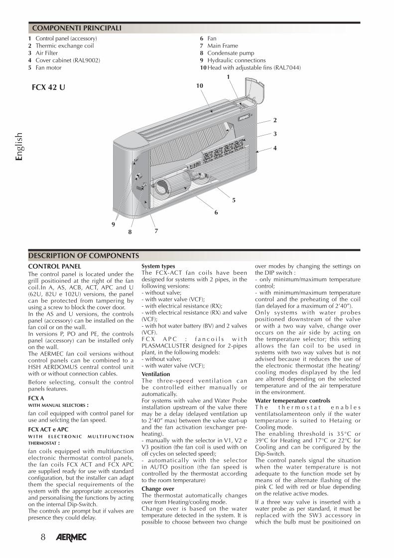
COMPONENTI PRINCIPALI
CONTROL PANELThe control panel is located under the grill positioined at the right of the fan coil.In A, AS, ACB, ACT, APC and U (62U, 82U e 102U) versions, the panel can be protected from tampering by using a screw to block the cover door. In the AS and U versions, the controls panel (accessory) can be installed on the fan coil or on the wall. In versions P, PO and PE, the controls panel (accessory) can be installed only on the wall. The AERMEC fan coil versions without control panels can be combined to a HSH AERDOMUS central control unit with or without connection cables.Before selecting, consult the control panels features.
FCX AWITH MANUAL SELECTORS :fan coil equipped with control panel for use and selcting the fan speed.
FCX ACT e APC W I T H E L E C T R O N I C M U LT I F U N C T I O N THERMOSTAT :fan coils equipped with multifunction electronic thermostat control panels, the fan coils FCX ACT and FCX APC are supplied ready for use with standard configuration, but the installer can adapt them the special requirements of the system with the appropriate accessories and personalising the functions by acting on the internal Dip-Switch.The controls are prompt but if valves are presence they could delay.
System typesThe FCX-ACT fan coils have been designed for systems with 2 pipes, in the following versions:- without valve;- with water valve (VCF);- with electrical resistance (RX);- with electrical resistance (RX) and valve (VCF);- with hot water battery (BV) and 2 valves (VCF).F C X A P C : f a n c o i l s w i t h PLASMACLUSTER designed for 2-pipes plant, in the following models:- without valve;- with water valve (VCF);VentilationThe three-speed vent i la t ion can be controlled either manually or automatically.For systems with valve and Water Probe installation upstream of the valve there may be a delay (delayed ventilation up to 2’40” max) between the valve start-up and the fan activation (exchanger pre-heating).- manually with the selector in V1, V2 e V3 position (the fan coil is used with on off cycles on selected speed);- automatically with the selector in AUTO position (the fan speed is controlled by the thermostat according to the room temperature)Change overThe thermostat automatically changes over from Heating/cooling mode.Change over is based on the water temperature detected in the system. It is possible to choose between two change
over modes by changing the settings on the DIP switch :- only minimum/maximum temperature control;- with minimum/maximum temperature control and the preheating of the coil (fan delayed for a maximum of 2’40”).Only systems with water probes positioned downstream of the valve or with a two way valve, change over occurs on the air side by acting on the temperature selector; this setting allows the fan coil to be used in systems with two way valves but is not advised because it reduces the use of the electronic thermostat (the heating/cooling modes displayed by the led are altered depending on the selected temperature and of the air temperature in the environment.Water temeperature controlsT h e t h e r m o s t a t e n a b l e s ventilatsolamenteon only if the water temperature is suited to Hetaing or Cooling mode. The enabling threshold is 35°C or 39°C for Heating and 17°C or 22°C for Cooling and can be configured by the Dip-Switch.The control panels signal the situation when the water temperature is not adequate to the function mode set by means of the alternate flashing of the pink C led with red or blue depending on the relative active modes.If a three way valve is inserted with a water probe as per standard, it must be replaced with the SW3 accessory in which the bulb must be positioined on
DESCRIPTION OF COMPONENTS
�
�
�
�
�
�
���
��FCX 42 U
1 Control panel (accessory) 2 Thermic exchange coil3 Air Filter4 Cover cabinet (RAL9002)5 Fan motor
6 Fan 7 Main Frame8 Condensate pump 9 Hydraulic connections 10 Head with adjustable fins (RAL7044)
9
Engl
ish
the delivery pipe upstream of the valve. Valve controlThe valve can be controlled in two ways::- optimised: uses the fan coil capacity in Heatingto produce heat even with ventilation off and in Cooling for a continuous ventilation controlling the room temperature by means of a valve;- normal: the valve opens and closes in correspondance with the switch on and switch off of the fan coil.Emergency modeIn case of probe troubleshooting SA, the thermostat enters in emergency mode, indicated by a flashing led (D) yellow. In this condition the thermostat behaves as follows::- with selector (A) in OFF position the water valave is closed and the fan is off.- with selector (A) in AUTO position, V1, V2 and V3 the water valve is always open and the fan performs on off cycles; in this situation, the power provided by the terminal is manually controlled by selcetor (B): turning towards the right the duration of the On cycle increases; turningn towards the left it reduces.
FCX ACB WITH SIMPLIFIED ELECTRONIC THERMOSTAT:fan coil equipped with control panel with electronic room thermostat for controlling switch on and switch off of the fan. The control panel controls the function of the fan coil in order to maintain the set room temperature. It allows the electronic adjustment of the temperature, manual speed change on the fan,manual function selection in Heating or Cooling mode (manual change over).The room probe temperature is located bext to the “AERMEC” plate.It is not possible to couple the thermostat with a water temperature probe.If the power supply is cut, the fan coils restarts resetting the previous modes set
The controls are prompt if the room temperature allows it. Water temperature control of the system is not foreseenType of systemThe fan coil series FCX ACB are designed for two pipe systems :- without valve;- with water valve (VCF);VentilationThe 3 speed fan is manually controlles with a selector positioned in V1, V2 and V3 (the fan is used with on off cycles on the speed selected).Change overChange over is manual, the user selects the function mode (Heating or Cooling) by acting on the selector of the controls panel.Valve controlThe valve (accessory) opens or closes in correspondance with the switching on and switching off of the fan .
HEAT EXCHANGE COIL Coil with copper pipe and finned in blocked aluminium by means of mechanical expansion pipes The collectors are attached with female connectors and air relief at the top of the coil.
FILTER SECTIONEasi ly removable and buil t with regenerised materialsand can be cleaned by washingVersions P and PO filters with filtration class G2.
CABINET CASE Colour RAL9002Delivery and Intake gril l colour RAL7044 The steel case is treated and coated with powered polyester to guarantee high rust resistance and corrosion.Versions A, AS, ACT, APC, ACB : are inserted with grills on the top in thermo plastic material for the diffusion of air
and with a door for accessing the control panel.Version U, UE : are inserted with adjustable grills on the top in thermo plastic material for the diffusion of air and with a door for accessing the control panel. With the adjustable grill closed, intervening on the micro switch stops the fan, interrupting any heat change with the room. The cabinet has a front grill in thermoplastic material for air intake. .
ELECTRO FAN UNITIt is made up of double inlet centrifugal fans with blades along its length for obtaining a high capacity with a low number of revs. The electric motor protects from over loads, it is three speed with condenser always inserted, directly coupled with the fans and with elastic supports. The FCX PO versions have 7 speed motors. (3 selections) .
SUPPORT STRUCTURE Made from thick galvanised steel The rear has holes for fitting the appliance to the wall For wall panels, a panel for closing the fan group is provided. Each appliance is supplied with a condensate drain tray
CONDENSATE DRAIN Each appliance is supplied with a condensate drain tray connected to the condensate outlet produced from the unit id cooling mode.
HYDRAULIC CONNECTIONSI The connections, positioned on the left side have female attachments. It is possible to rotate the coil.
PACKINGThe units are shipped in cardboard box standard packing and polystirene shells.
10
Engl
ish
CRITERIA OF CHOICE
The versions with high cabinet (A, AS, ACB, ACT and APC) have intake from below and can be used for vertical wall-hung or floor installation using the rele-vant skirting (accessory ZX). The acces-sory SE (external air damper) where requested, also allows, to change the environment air.The versions with universal cabinet (U and UE) have front intake and can be vertically wall-hung or installed hori-zontally on the ceiling.The suspended versions (P, PPC, PO and PE), without cover cabinets and intake from below, are suitable for vertical or horizontal installation. In the case of ducted installations where the loss of load of the channel is rele-vant, the PO version (with multi-speed enhanced motor) allows to obtain the static pressure necessary to guarantee a correct air flow rate.The PO version is available with coils with 3 and 4 rows.The AS, U, UE versions require coupling with a control panel to be applied insi-de or outside, consult the features and the compatibility of the control panels supplied as accessories. The P, PE and PO require coupling with a control panel to be applied outside, consult the features and the compati-bility of the control panels supplied as accessories.The PPC version must be coupled to panel PXA E.The other versions of fan coil are sup-plied with incorporated control panel.Some control panels can control a net-work of fan coils if they are combined with the SIT3 and SIT5 interface board supplied as an accessory. In the versions without control panels, the AERMEC fan coils can all be coupled to the centralised HSH AERDOMUS control system with wired or wireless connection.The main technical data of the FCX are summarised in the tables.
The sensitive and total cooling capa-city at maximum speed depending on the temperature of the inlet water, its heat drop and the dry and wet bulb temperatures of the air respectively for sensitive capacity and total capacity for the versions with coils with 3 rows are stated in the table. The efficiency at ave-rage and minimum speed is obtained by multiplying the table values by the cor-rective factors indicate. For the versions with 4 rows, they are obtained by multi-plying the table values by the corrective factors indicated for every speed.The water side pressure drop for the coils with 3, 1 and 4 rows is respective-ly stated in the graphics.The correction factors in functioning with glycoled water in cooling mode and in heating mode are stated in the graphics per percentages of glycol of 10%, 20% and 35%.The heating capacity of the coils with 3, 4 and 1 row (accessory BV) depending on the water flow rate and the tempe-rature difference between inlet water and inlet air is stated in a graphical form and is referred at maximum speed. Performance at average and minimum speed is obtained by multiplying the values obtained from the graphics at maximum speed by the indicated cor-rective factors.The sensitive and total cooling capaci-ties of the direct expansion coils (FCX PE) depending on the evaporation tem-perature and the dry and wet bulb tem-peratures of the air entering are stated in the graphical form respectively for total and sensitive capacity and are stated at maximum speed. Performance at ave-rage and minimum speed is obtained by multiplying the values obtained from the graphics at maximum speed by the indicated corrective factors.For the ducted, suspended versions (P-PE-PO) the performance stated above must be intended as referring to air flow rates equal to those of corresponding models of other versions (A-U) at maxi-mum speed (nominal flow rate).
The head of the suspended versions, depending on the air flow rate and fan speed, are stated in table form. The cur-ves are indicated for every speed.For dimensioning of the ducted, suspen-ded versions, it is recommended to pro-ceed as follows: select the size which, in nominal flow rate conditions, have immediate power that is higher than that requested; trace the curve of the channel pressure drop on the flow rate-static pressure diagram relative to the machine in question, thus identify the functioning points of the machine at the different speeds. On the basis of the flow rate values corresponding to the above-mentioned points, the corrective factors are finally obtained that allow to calculate the power yielded in real air flow conditions. The above-mentioned procedure allows, in the case of multi-speed versions, to appropriately choose the speed to be set.The sound power and sound pressu-re level of the fan coils at the various speeds is stated in separate tables for the versions with 3 rows and versions with 4 rows. For ducted, suspended ver-sions, the sound power level is expres-sed depending on the air flow rate and static pressure and is represented using graphics.A wide range of accessories is avai-lable for FCX series fan coils, someti-mes some of them cannot be used at the same time. The compatibility of the accessories with the selected fan coil must be checked. The manual contains the description, drawing and compatibi-lity of each accessory.The information regarding installation is inserted in the manual supplied with every fan coil and every accessory. This manual is limited to general information in order to perform correct installation. There are also drawings with dimen-sions of the fan coils and wiring dia-grams with connections to the control panels.
11
Engl
ish
��� ���
��� ���
��� ���
�� �� ��
�� ��
��� ���
��
���
�
����
��� ��� ���
����
���
����
���
����
���
����
���
���� ��
���
�� �
����
�� �
����
��
����
���
��� ���
��� ���
����� ���
�� �� �� �
� �� �� �
��� ���
� ��
���
� �
����
���
�
���
�
���
� ����
���
� ����
���
���� �
���
����
���
���� ��
���
�� �
����
�� �
����
��
�
����
���
�
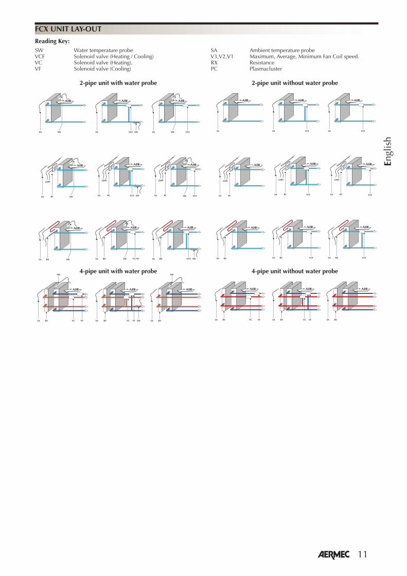
2-pipe unit with water probe
SW Water temperature probeVCF Solenoid valve (Heating / Cooling)VC Solenoid valve (Heating), VF Solenoid valve (Cooling)
SA Ambient temperature probeV3,V2,V1 Maximum, Average, Minimum Fan Coil speed.RX ResistancePC Plasmacluster
FCX UNIT LAY-OUT
2-pipe unit without water probe
4-pipe unit with water probe 4-pipe unit without water probe
Reading Key:
12
Engl
ish
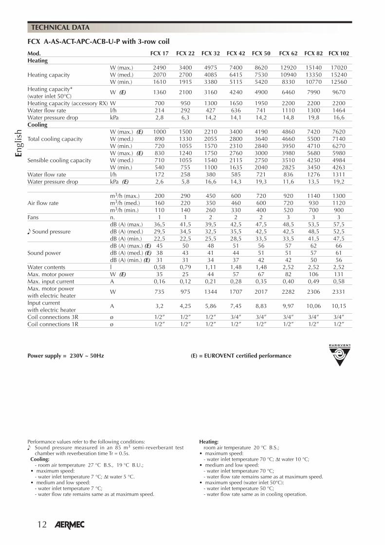
TECHNICAL DATA
Performance values refer to the following conditions:� Sound pressure measured in an 85 m3 semi-reverberant test chamber with reverberation time Tr = 0.5s.
Cooling: - room air temperature 27 °C B.S., 19 °C B.U.; • maximum speed: - water inlet temperature 7 °C; ∆t water 5 °C. • medium and low speed: - water inlet temperature 7 °C; - water flow rate remains same as at maximum speed.
Heating: room air temperature 20 °C B.S.; • maximum speed: - water inlet temperature 70 °C; ∆t water 10 °C; • medium and low speed: - water inlet temperature 70 °C; - water flow rate remains same as at maximum speed. • maximum speed (water inlet 50°C): - water inlet temperature 50 °C; - water flow rate same as in cooling operation.
FCX 17 FCX 22 FCX 32 FCX 42 FCX 50 FCX 62 FCX 82 FCX 102
2490 3400 4975 7400 8620 12920 15140 17020 2070 2700 4085 6415 7530 10940 13350 15240 1610 1915 3380 5115 5420 8330 10770 12560 1360 2100 3160 4240 4900 6460 7990 9670
700 950 1300 1650 1950 2200 2200 2200 214 292 427 636 741 1110 1300 1464 2,8 6,3 14,2 14,1 14,2 14,8 19,8 16,6
1000 1500 2210 3400 4190 4860 7420 7620 890 1330 2055 2800 3640 4660 5500 7140 720 1055 1570 2310 2840 3950 4710 6270 830 1240 1750 2760 3000 3980 5680 5980 710 1055 1540 2115 2750 3510 4250 4984 540 755 1100 1635 2040 2825 3450 4263 172 258 380 585 721 836 1276 1311 2,6 5,8 16,6 14,3 19,3 11,6 13,5 19,2
200 290 450 600 720 920 1140 1300 160 220 350 460 600 720 930 1120 110 140 260 330 400 520 700 900 1 1 2 2 2 3 3 3 36,5 41,5 39,5 42,5 47,5 48,5 53,5 57,5 29,5 34,5 32,5 35,5 42,5 42,5 48,5 52,5 22,5 22,5 25,5 28,5 33,5 33,5 41,5 47,5 45 50 48 51 56 57 62 66 38 43 41 44 51 51 57 61 31 31 34 37 42 42 50 56 0,58 0,79 1,11 1,48 1,48 2,52 2,52 2,52 35 25 44 57 67 82 106 131 0,16 0,12 0,21 0,28 0,35 0,40 0,49 0,58 735 975 1344 1707 2017 2282 2306 2331
3,2 4,25 5,86 7,45 8,83 9,97 10,06 10,15
1/2” 1/2” 1/2” 3/4” 3/4” 3/4” 3/4” 3/4” 1/2” 1/2” 1/2” 1/2” 1/2” 1/2” 1/2” 1/2”
Mod. Heating W (max.)Heating capacity W (med.) W (min.)Heating capacity* W (E)(water inlet 50°C)Heating capacity (accessory RX) WWater flow rate l/hWater pressure drop kPaCooling W (max.) (E)Total cooling capacity W (med.) W (min.) W (max.) (E)Sensible cooling capacity W (med.) W (min.)Water flow rate l/hWater pressure drop kPa (E)
m3/h (max.)Air flow rate m3/h (med.) m3/h (min.)Fans n. dB (A) (max.)� Sound pressure dB (A) (med.) dB (A) (min.) dB (A) (max.) (E)Sound power dB (A) (med.) (E) dB (A) (min.) (E)Water contents lMax. motor power W (E)Max. input current AMax. motor power Wwith electric heaterInput current Awith electric heaterCoil connections 3R øCoil connections 1R ø
FCX A-AS-ACT-APC-ACB-U-P with 3-row coil
Power supply = 230V ~ 50Hz (E) = EUROVENT certified performance
13
Engl
ish
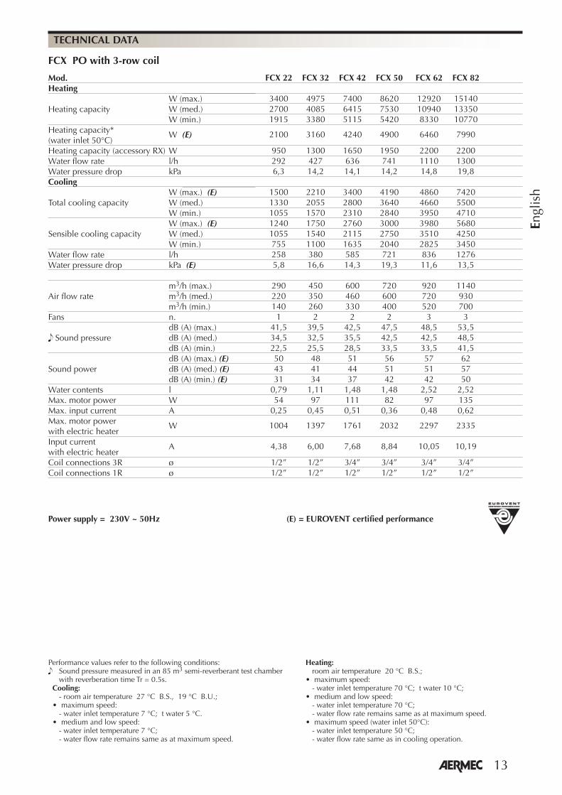
TECHNICAL DATA
Performance values refer to the following conditions:� Sound pressure measured in an 85 m3 semi-reverberant test chamber with reverberation time Tr = 0.5s.
Cooling: - room air temperature 27 °C B.S., 19 °C B.U.; • maximum speed: - water inlet temperature 7 °C; t water 5 °C. • medium and low speed: - water inlet temperature 7 °C; - water flow rate remains same as at maximum speed.
Heating: room air temperature 20 °C B.S.; • maximum speed: - water inlet temperature 70 °C; t water 10 °C; • medium and low speed: - water inlet temperature 70 °C; - water flow rate remains same as at maximum speed. • maximum speed (water inlet 50°C): - water inlet temperature 50 °C; - water flow rate same as in cooling operation.
FCX 22 FCX 32 FCX 42 FCX 50 FCX 62 FCX 82
3400 4975 7400 8620 12920 15140 2700 4085 6415 7530 10940 13350 1915 3380 5115 5420 8330 10770 2100 3160 4240 4900 6460 7990
950 1300 1650 1950 2200 2200 292 427 636 741 1110 1300 6,3 14,2 14,1 14,2 14,8 19,8
1500 2210 3400 4190 4860 7420 1330 2055 2800 3640 4660 5500 1055 1570 2310 2840 3950 4710 1240 1750 2760 3000 3980 5680 1055 1540 2115 2750 3510 4250 755 1100 1635 2040 2825 3450 258 380 585 721 836 1276 5,8 16,6 14,3 19,3 11,6 13,5
290 450 600 720 920 1140 220 350 460 600 720 930 140 260 330 400 520 700 1 2 2 2 3 3 41,5 39,5 42,5 47,5 48,5 53,5 34,5 32,5 35,5 42,5 42,5 48,5 22,5 25,5 28,5 33,5 33,5 41,5 50 48 51 56 57 62 43 41 44 51 51 57 31 34 37 42 42 50 0,79 1,11 1,48 1,48 2,52 2,52 54 97 111 82 97 135 0,25 0,45 0,51 0,36 0,48 0,62 1004 1397 1761 2032 2297 2335
4,38 6,00 7,68 8,84 10,05 10,19
1/2” 1/2” 3/4” 3/4” 3/4” 3/4” 1/2” 1/2” 1/2” 1/2” 1/2” 1/2”
Mod. Heating W (max.)Heating capacity W (med.) W (min.)Heating capacity* W (E)(water inlet 50°C)Heating capacity (accessory RX) WWater flow rate l/hWater pressure drop kPaCooling W (max.) (E)Total cooling capacity W (med.) W (min.) W (max.) (E)Sensible cooling capacity W (med.) W (min.)Water flow rate l/hWater pressure drop kPa (E)
m3/h (max.)Air flow rate m3/h (med.) m3/h (min.)Fans n. dB (A) (max.)� Sound pressure dB (A) (med.) dB (A) (min.) dB (A) (max.) (E)Sound power dB (A) (med.) (E) dB (A) (min.) (E)Water contents lMax. motor power WMax. input current AMax. motor power Wwith electric heaterInput current Awith electric heaterCoil connections 3R øCoil connections 1R ø
FCX PO with 3-row coil
Power supply = 230V ~ 50Hz (E) = EUROVENT certified performance

14
Engl
ish
TECHNICAL DATA
Performance values refer to the following conditions:� Sound pressure measured in an 85 m3 semi-reverberant test chamber with reverberation time Tr = 0.5s.
Cooling: - room air temperature 27 °C B.S., 19 °C B.U.; • maximum speed: - water inlet temperature 7 °C; ∆t water 5 °C. • medium and low speed: - water inlet temperature 7 °C; - water flow rate remains same as at maximum speed.
Heating: room air temperature 20 °C B.S.; • maximum speed: - water inlet temperature 70 °C; ∆t water 10 °C; • medium and low speed: - water inlet temperature 70 °C; - water flow rate remains same as at maximum speed. • maximum speed (water inlet 50°C): - water inlet temperature 50 °C; - water flow rate same as in cooling operation.
FCX 24 FCX 34 FCX 44 FCX 54 FCX 64 FCX 84
3950 5850 8600 10100 14300 17100 3200 4850 6930 8760 11500 14420 2200 3850 5200 6240 8500 11200 2320 3550 5250 6100 7810 10400 340 503 740 869 1230 1471 4 8 21 22 22 30
1730 2800 4450 4970 6350 8600 1500 2450 3780 4770 5520 7600 1150 2050 2970 3620 4500 6270 1380 2130 3300 3540 5030 5780 1140 1789 2722 3101 4195 5016 828 1441 2079 2281 3330 4013 297 482 765 855 1092 1479 3 9 19,2 25,9 13 22
290 450 600 720 920 1140 220 350 460 600 720 930 140 260 330 400 520 700 1 2 2 2 3 3 42,5 39,5 46,5 47,5 48,5 52,5 37,5 32,5 41,5 44,5 42,5 48,5 26,5 27,5 32,5 35,5 35,5 42,5 51 48 55 56 57 61 46 41 50 53 51 57 35 36 41 44 44 51 1 1,5 1,9 1,9 3,4 3,4 33 44 57 67 91 106 0,25 0,45 0,51 0,36 0,48 0,62 3/4” 3/4” 3/4” 3/4” 3/4” 3/4”
Mod. Heating W (max.)Heating capacity W (med.) W (min.)Heating capacity* W (E)(water inlet 50°C)Water flow rate l/hWater pressure drop kPaCooling W (max.) (E)Total cooling capacity W (med.) W (min.) W (max.) (E)Sensible cooling capacity W (med.) W (min.)Water flow rate l/hWater pressure drop kPa (E)
m3/h (max.)Air flow rate m3/h (med.) m3/h (min.)Fans n. dB (A) (max.)� Sound pressure dB (A) (med.) dB (A) (min.) dB (A) (max.) (E)Sound power dB (A) (med.) (E) dB (A) (min.) (E)Water contents lMax. motor power W (E)Max. input current ACoil connections 4R ø
FCX P with 4-row coil
Power supply = 230V ~ 50Hz (E) = EUROVENT certified performance

15
Engl
ish
TECHNICAL DATA
Performance values refer to the following conditions:� Sound pressure measured in an 85 m3 semi-reverberant test chamber with reverberation time Tr = 0.5s.
Cooling:- room air temperature 27 °C B.S., 19 °C B.U.; • maximum speed: - water inlet temperature 7 °C; t water 5 °C. • medium and low speed: - water inlet temperature 7 °C; - water flow rate remains same as at maximum speed.
Heating:- room air temperature 20 °C B.S.; • maximum speed: - water inlet temperature 70 °C; t water 10 °C; • medium and low speed: - water inlet temperature 70 °C; - water flow rate remains same as at maximum speed. • maximum speed (water inlet 50°C): - water inlet temperature 50 °C; - water flow rate same as in cooling operation.
FCX 24 FCX 34 FCX 44 FCX 54 FCX 64 FCX 84
3950 5850 8600 10100 14300 17100 3200 4850 6930 8760 11500 14420 2200 3850 5200 6240 8500 11200 2320 3550 5250 6100 7810 10400 340 503 740 869 1230 1471 4 8 21 22 22 30
1730 2800 4450 4970 6350 8600 1500 2450 3780 4770 5520 7600 1150 2050 2970 3620 4500 6270 1380 2130 3300 3540 5030 5780 1140 1789 2722 3101 4195 5016 828 1441 2079 2281 3330 4013 297 482 765 855 1092 1479 3 9 19,2 25,9 13 22
290 450 600 720 920 1140 220 350 460 600 720 930 140 260 330 400 520 700 1 2 2 2 3 3 49,5 44 50 50,5 53,5 55,5 58 52,5 58,5 59 62 64 1 1,5 1,9 1,9 3,4 3,4 54 97 111 82 97 135 0,25 0,45 0,51 0,36 0,48 0,62 3/4” 3/4” 3/4” 3/4” 3/4” 3/4”
Mod. Heating W (max.)Heating capacity W (med.) W (min.)Heating capacity* W (E)(water inlet 50°C)Water flow rate l/hWater pressure drop kPaCooling W (max.) (E)Total cooling capacity W (med.) W (min.) W (max.) (E)Sensible cooling capacity W (med.) W (min.)Water flow rate l/hWater pressure drop kPa (E)
m3/h (max.)Air flow rate m3/h (med.) m3/h (min.)Fans n.� Sound pressure dB (A) (max.)Sound power dB (A) (max.) Water contents lMax. motor power W (E)Max. input current ACoil connections 4R ø
FCX PO with 4-row coil
Power supply = 230V ~ 50Hz (E) = EUROVENT certified performance

16
Engl
ish
MINIMUM AVERAGE WATER TEMPERATURE Dry bulbe air temperature [°C] 21 23 25 27 29 31 15 3 3 3 3 3 3Wet bulbe air temperature °C 17 3 3 3 3 3 3 19 3 3 3 3 3 3 21 6 5 4 3 3 3 23 - 8 7 6 5 5
Maximum water inlet temperature ............................ 80 °CMaximum working pressure ....................................... 8 barOperating Voltage ..............................230V(±10%) ~ 50HzRoom Temperature ................................................. 0÷45°CRoom Humidity .................................................<85% U.R.
To prevent the formation of condensation on the exterior ofthe unit while the fan is operating, the average water temperature should not drop beneath the limits shown in the table below, determined by the thermo-hydrometric ambient conditions. These limits refer to unit operation with fan at minimum speed.
In case condensation is formed on the exterior of the unitif cold water circulates through the coil while the fan is offfor prolonged periods of time, it is advisable to fit theadditional three-way valve.
Water flow limits (3-row coil ):
MOD. FCX 17 22 32 42 50 62 82 102Minimum water flow [l/h] 100 100 100 150 150 300 300 300Maximum water flow [l/h] 750 750 750 1100 1100 2200 2200 2200
OPERATING LIMITS
Water flow limits (1-row coil):
MOD. FCX 17 22 32 42 50 62 82 102Minimum water flow [l/h] 50 50 50 50 50 100 100 100Maximum water flow [l/h] 400 400 400 400 400 900 900 900
Water flow limits (4-row coil):
MOD. FCX 24 34 44 54 64 84Minimum water flow [l/h] 150 150 150 150 300 300Maximum water flow [l/h] 1100 1100 1100 1100 2200 2200
Minimum average water temperature

17
Engl
ish
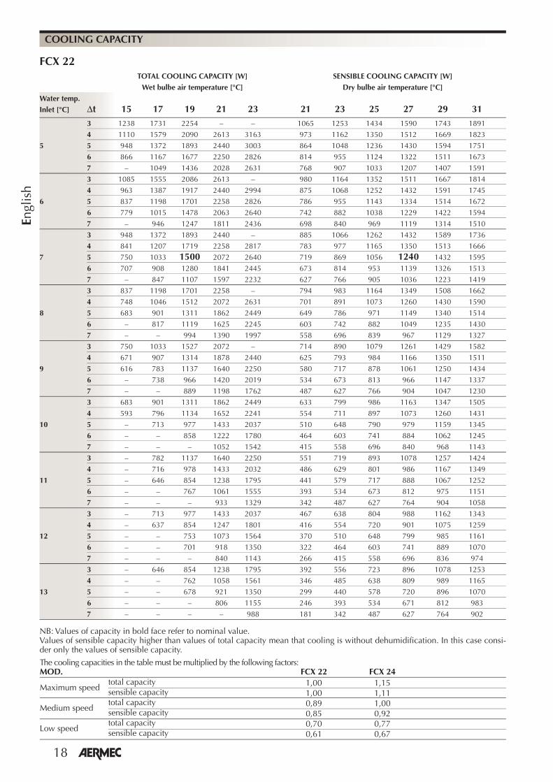
COOLING CAPACITY
FCX 17 TOTAL COOLING CAPACITY [W] SENSIBLE COOLING CAPACITY [W]
Wet bulbe air temperature [°C] Dry bulbe air temperature [°C]
Water temp.
Inlet [°C] ∆t 15 17 19 21 23 21 23 25 27 29 31 3 884 1246 1624 2012 2428 723 857 996 1112 1226 1337
4 750 1071 1472 1866 2286 652 768 907 1044 1161 1276
5 5 699 920 1277 1710 2137 615 718 820 956 1093 1211
6 – 852 1105 1525 1975 583 685 781 877 1011 1145
7 – – 1027 1328 1803 548 652 747 835 933 1068
3 777 1109 1495 1882 2299 654 786 923 1054 1170 1282
4 674 934 1328 1734 2157 595 711 840 980 1104 1220
6 5 627 823 1141 1572 2002 562 666 768 895 1029 1155
6 – 768 991 1364 1833 530 635 731 823 945 1086
7 – – 927 1191 1638 498 601 699 791 879 1001
3 671 964 1362 1750 2167 589 727 858 995 1113 1226
4 602 825 1171 1595 2021 544 652 780 911 1046 1163
7 5 – 736 1000 1403 1859 512 615 716 830 966 1096
6 – – 891 1209 1684 480 580 683 777 879 1018
7 – – 837 1075 1466 447 548 649 744 832 936
3 597 845 1212 1615 2031 532 658 796 930 1054 1168
4 551 718 1036 1452 1879 493 595 717 849 982 1105
8 5 – 660 875 1252 1710 461 562 667 769 899 1038
6 – – 807 1061 1505 429 530 634 730 822 954
7 – – – 970 1296 395 497 600 695 788 878
3 539 727 1055 1472 1889 477 594 728 859 995 1110
4 500 635 900 1282 1730 443 544 654 784 912 1046
9 5 – 593 775 1098 1555 411 512 614 715 835 969
6 – – 725 941 1346 378 479 579 682 771 891
7 – – – 878 1146 345 446 548 649 739 827
3 481 630 920 1309 1744 425 536 662 797 930 1053
4 – 575 779 1118 1578 392 493 594 722 851 982
10 5 – – 694 955 1378 360 461 561 665 773 903
6 – – – 843 1177 326 429 530 631 725 828
7 – – – – 1023 292 395 497 600 694 782
3 429 572 788 1152 1591 374 479 598 731 860 993
4 – 525 679 982 1405 342 443 543 659 787 918
11 5 – – 622 829 1205 310 410 510 614 716 839
6 – – – 757 1027 275 378 479 579 678 770
7 – – – – 918 238 344 446 547 648 737
3 – 514 679 986 1432 324 425 541 665 798 928
4 – 473 600 845 1227 292 392 492 595 725 853
12 5 – – – 730 1045 258 360 461 561 664 778
6 – – – – 891 222 326 428 528 630 723
7 – – – – 826 182 292 395 497 599 693
3 – 456 605 856 1259 273 374 483 602 732 858
4 – – 547 732 1071 240 341 442 542 664 789
13 5 – – – 654 904 206 309 410 510 614 720
6 – – – – 795 167 275 377 479 578 678
7 – – – – – 120 238 343 446 547 648
NB: Values of capacity in bold face refer to nominal value.Values of sensible capacity higher than values of total capacity mean that cooling is without dehumidification. In this case consi-der only the values of sensible capacity.
The cooling capacities in the table must be multiplied by the following factors: MOD. FCX 17
Maximun speed total capacity 1,00
sensible capacity 1,00
Medium speed total capacity 0,89
sensible capacity 0,86
Minimum speed total capacity 0,72
sensible capacity 0,65
18
Engl
ish
COOLING CAPACITY
FCX 22 TOTAL COOLING CAPACITY [W] SENSIBLE COOLING CAPACITY [W]
Wet bulbe air temperature [°C] Dry bulbe air temperature [°C]
Water temp.
Inlet [°C] ∆t 15 17 19 21 23 21 23 25 27 29 31 3 1238 1731 2254 – – 1065 1253 1434 1590 1743 1891
4 1110 1579 2090 2613 3163 973 1162 1350 1512 1669 1823
5 5 948 1372 1893 2440 3003 864 1048 1236 1430 1594 1751
6 866 1167 1677 2250 2826 814 955 1124 1322 1511 1673
7 – 1049 1436 2028 2631 768 907 1033 1207 1407 1591
3 1085 1555 2086 2613 – 980 1164 1352 1511 1667 1814
4 963 1387 1917 2440 2994 875 1068 1252 1432 1591 1745
6 5 837 1198 1701 2258 2826 786 955 1143 1334 1514 1672
6 779 1015 1478 2063 2640 742 882 1038 1229 1422 1594
7 – 946 1247 1811 2436 698 840 969 1119 1314 1510
3 948 1372 1893 2440 – 885 1066 1262 1432 1589 1736
4 841 1207 1719 2258 2817 783 977 1165 1350 1513 1666
7 5 750 1033 1500 2072 2640 719 869 1056 1240 1432 1595
6 707 908 1280 1841 2445 673 814 953 1139 1326 1513
7 – 847 1107 1597 2232 627 766 905 1036 1223 1419
3 837 1198 1701 2258 – 794 983 1164 1349 1508 1662
4 748 1046 1512 2072 2631 701 891 1073 1260 1430 1590
8 5 683 901 1311 1862 2449 649 786 971 1149 1340 1514
6 – 817 1119 1625 2245 603 742 882 1049 1235 1430
7 – – 994 1390 1997 558 696 839 967 1129 1327
3 750 1033 1527 2072 – 714 890 1079 1261 1429 1582
4 671 907 1314 1878 2440 625 793 984 1166 1350 1511
9 5 616 783 1137 1640 2250 580 717 878 1061 1250 1434
6 – 738 966 1420 2019 534 673 813 966 1147 1337
7 – – 889 1198 1762 487 627 766 904 1047 1230
3 683 901 1311 1862 2449 633 799 986 1163 1347 1505
4 593 796 1134 1652 2241 554 711 897 1073 1260 1431
10 5 – 713 977 1433 2037 510 648 790 979 1159 1345
6 – – 858 1222 1780 464 603 741 884 1062 1245
7 – – – 1052 1542 415 558 696 840 968 1143
3 – 782 1137 1640 2250 551 719 893 1078 1257 1424
4 – 716 978 1433 2032 486 629 801 986 1167 1349
11 5 – 646 854 1238 1795 441 579 717 888 1067 1252
6 – – 767 1061 1555 393 534 673 812 975 1151
7 – – – 933 1329 342 487 627 764 904 1058
3 – 713 977 1433 2037 467 638 804 988 1162 1343
4 – 637 854 1247 1801 416 554 720 901 1075 1259
12 5 – – 753 1073 1564 370 510 648 799 985 1161
6 – – 701 918 1350 322 464 603 741 889 1070
7 – – – 840 1143 266 415 558 696 836 974
3 – 646 854 1238 1795 392 556 723 896 1078 1253
4 – – 762 1058 1561 346 485 638 809 989 1165
13 5 – – 678 921 1350 299 440 578 720 896 1070
6 – – – 806 1155 246 393 534 671 812 983
7 – – – – 988 181 342 487 627 764 902
NB: Values of capacity in bold face refer to nominal value.Values of sensible capacity higher than values of total capacity mean that cooling is without dehumidification. In this case consi-der only the values of sensible capacity.
The cooling capacities in the table must be multiplied by the following factors: MOD. FCX 22 FCX 24
Maximum speed total capacity 1,00 1,15
sensible capacity 1,00 1,11
Medium speed total capacity 0,89 1,00
sensible capacity 0,85 0,92
Low speed total capacity 0,70 0,77
sensible capacity 0,61 0,67
19
Engl
ish
COOLING CAPACITY
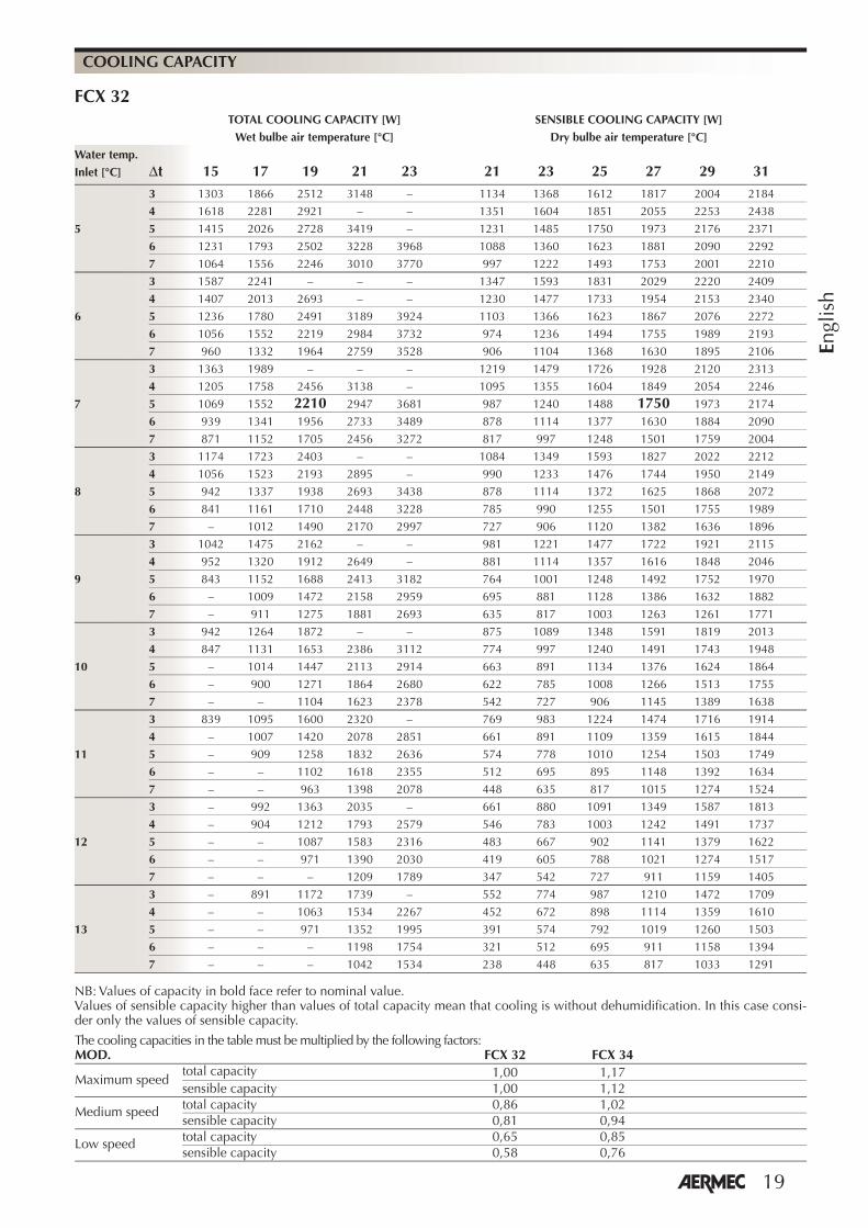
FCX 32
The cooling capacities in the table must be multiplied by the following factors:MOD. FCX 32 FCX 34
Maximum speed total capacity 1,00 1,17
sensible capacity 1,00 1,12
Medium speed total capacity 0,86 1,02
sensible capacity 0,81 0,94
Low speed total capacity 0,65 0,85
sensible capacity 0,58 0,76
TOTAL COOLING CAPACITY [W] SENSIBLE COOLING CAPACITY [W]
Wet bulbe air temperature [°C] Dry bulbe air temperature [°C]
Water temp.
Inlet [°C] ∆t 15 17 19 21 23 21 23 25 27 29 31 3 1303 1866 2512 3148 – 1134 1368 1612 1817 2004 2184
4 1618 2281 2921 – – 1351 1604 1851 2055 2253 2438
5 5 1415 2026 2728 3419 – 1231 1485 1750 1973 2176 2371
6 1231 1793 2502 3228 3968 1088 1360 1623 1881 2090 2292
7 1064 1556 2246 3010 3770 997 1222 1493 1753 2001 2210
3 1587 2241 – – – 1347 1593 1831 2029 2220 2409
4 1407 2013 2693 – – 1230 1477 1733 1954 2153 2340
6 5 1236 1780 2491 3189 3924 1103 1366 1623 1867 2076 2272
6 1056 1552 2219 2984 3732 974 1236 1494 1755 1989 2193
7 960 1332 1964 2759 3528 906 1104 1368 1630 1895 2106
3 1363 1989 – – – 1219 1479 1726 1928 2120 2313
4 1205 1758 2456 3138 – 1095 1355 1604 1849 2054 2246
7 5 1069 1552 2210 2947 3681 987 1240 1488 1750 1973 2174
6 939 1341 1956 2733 3489 878 1114 1377 1630 1884 2090
7 871 1152 1705 2456 3272 817 997 1248 1501 1759 2004
3 1174 1723 2403 – – 1084 1349 1593 1827 2022 2212
4 1056 1523 2193 2895 – 990 1233 1476 1744 1950 2149
8 5 942 1337 1938 2693 3438 878 1114 1372 1625 1868 2072
6 841 1161 1710 2448 3228 785 990 1255 1501 1755 1989
7 – 1012 1490 2170 2997 727 906 1120 1382 1636 1896
3 1042 1475 2162 – – 981 1221 1477 1722 1921 2115
4 952 1320 1912 2649 – 881 1114 1357 1616 1848 2046
9 5 843 1152 1688 2413 3182 764 1001 1248 1492 1752 1970
6 – 1009 1472 2158 2959 695 881 1128 1386 1632 1882
7 – 911 1275 1881 2693 635 817 1003 1263 1261 1771
3 942 1264 1872 – – 875 1089 1348 1591 1819 2013
4 847 1131 1653 2386 3112 774 997 1240 1491 1743 1948
10 5 – 1014 1447 2113 2914 663 891 1134 1376 1624 1864
6 – 900 1271 1864 2680 622 785 1008 1266 1513 1755
7 – – 1104 1623 2378 542 727 906 1145 1389 1638
3 839 1095 1600 2320 – 769 983 1224 1474 1716 1914
4 – 1007 1420 2078 2851 661 891 1109 1359 1615 1844
11 5 – 909 1258 1832 2636 574 778 1010 1254 1503 1749
6 – – 1102 1618 2355 512 695 895 1148 1392 1634
7 – – 963 1398 2078 448 635 817 1015 1274 1524
3 – 992 1363 2035 – 661 880 1091 1349 1587 1813
4 – 904 1212 1793 2579 546 783 1003 1242 1491 1737
12 5 – – 1087 1583 2316 483 667 902 1141 1379 1622
6 – – 971 1390 2030 419 605 788 1021 1274 1517
7 – – – 1209 1789 347 542 727 911 1159 1405
3 – 891 1172 1739 – 552 774 987 1210 1472 1709
4 – – 1063 1534 2267 452 672 898 1114 1359 1610
13 5 – – 971 1352 1995 391 574 792 1019 1260 1503
6 – – – 1198 1754 321 512 695 911 1158 1394
7 – – – 1042 1534 238 448 635 817 1033 1291
NB: Values of capacity in bold face refer to nominal value.Values of sensible capacity higher than values of total capacity mean that cooling is without dehumidification. In this case consi-der only the values of sensible capacity.

20
Engl
ish
COOLING CAPACITY
FCX 42
The cooling capacities in the table must be multiplied by the following factors: MOD. FCX 42 FCX 44
Maximum speed total capacity 1,00 1,31
sensible capacity 1,00 1,20
Medium speed total capacity 0,82 1,11
sensible capacity 0,77 0,99
Low speed total capacity 0,68 0,87
sensible capacity 0,59 0,75
TOTAL COOLING CAPACITY [W] SENSIBLE COOLING CAPACITY [W]
Wet bulbe air temperature [°C] Dry bulbe air temperature [°C]
Water temp.
Inlet [°C] ∆t 15 17 19 21 23 21 23 25 27 29 31 3 2871 – – – – 2336 2730 3088 3401 3715 –
4 2491 3516 4551 – – 2149 2550 2942 3279 3602 3907
5 5 2156 3110 4241 5329 – 1920 2332 2752 3134 3468 3791
6 1808 2717 3825 5010 6191 1648 2113 2530 2955 3320 3653
7 1602 2278 3368 4635 5854 1544 1850 2298 2737 3155 3507
3 2491 3497 – – – 2131 2542 2918 3240 3552 –
4 2166 3103 4194 – – 1939 2349 2755 3112 3437 3749
6 5 1879 2730 3832 4963 6126 1706 2143 2554 2962 3303 3628
6 1563 2343 3426 4626 5816 1496 1908 2337 2754 3150 3489
7 1457 1924 2962 4204 5460 1402 1685 2094 2528 2951 3339
3 2146 3071 – – – 1929 2336 2730 3076 3393 3702
4 1882 2742 3825 4898 – 1740 2160 2553 2941 3275 3592
7 5 1621 2375 3400 4579 5751 1523 1944 2343 2760 3133 3465
6 1415 2014 2987 4223 5423 1355 1679 2138 2558 2960 3322
7 1321 1689 2556 3471 5048 1260 1544 1878 2338 2754 3163
3 1850 2704 3761 – – 1740 2136 2539 2909 3228 3540
4 1647 2382 3381 4523 – 1564 1948 2357 2754 3108 3429
8 5 1482 2040 3013 4185 5357 1334 1751 2160 2561 2958 3298
6 1279 1737 2601 3748 5010 1216 1507 1940 2353 2761 3151
7 – 1518 2195 3297 4616 1118 1402 1695 2140 2559 2975
3 1644 2324 3342 – – 1571 1934 2334 2739 3064 3379
4 1482 2033 2987 4128 – 1388 1753 2166 2554 2936 3267
9 5 1266 1782 2588 3741 4954 1169 1557 1962 2369 2758 3131
6 – 1515 2233 3297 4588 1074 1355 1733 2172 2565 2964
7 – 1386 1859 2846 4109 976 1260 1540 1932 2362 2760
3 1482 1995 2936 – – 1398 1746 2135 2536 2899 3215
4 1312 1769 2581 3683 4869 1203 1581 1961 2357 2750 3100
10 5 – 1563 2246 3284 4532 1027 1368 1772 2169 2560 2956
6 – 1350 1924 2846 4109 932 1214 1534 1977 2380 2762
7 – – 1615 2446 3619 831 1118 1402 1718 2169 2573
3 1320 1727 2517 3625 – 1224 1577 1938 2333 2732 3052
4 – 1579 2195 3245 4448 1010 1405 1767 2168 2547 2929
11 5 – 1392 1927 2852 4083 885 1179 1584 1990 2373 2757
6 – – 1647 2465 3613 788 1074 1361 1770 2186 2570
7 – – 1450 2098 3155 684 976 1260 1547 1966 2373
3 – 1566 2149 3149 – 1047 1407 1753 2136 2529 2883
4 – 1412 1901 2800 4012 841 1226 1598 1984 2356 2741
12 5 – – 1669 2433 3580 744 1027 1402 1794 2177 2561
6 – – 1466 2117 3142 642 932 1213 1574 1999 2385
7 – – – 1789 2710 529 831 1118 1402 1768 2189
3 – 1405 1850 2730 – 863 1233 1584 1945 2329 2717
4 – – 1669 2375 3535 698 1037 1422 1780 2172 2545
13 5 – – 1502 2104 3103 600 885 1206 1604 2003 2374
6 – – – 1824 2691 491 788 1072 1382 1808 2195
7 – – – 1544 2317 359 684 976 1260 1564 2004
NB: Values of capacity in bold face refer to nominal value.Values of sensible capacity higher than values of total capacity mean that cooling is without dehumidification. In this case consi-der only the values of sensible capacity.

21
Engl
ish
COOLING CAPACITY
FCX 50
The cooling capacities in the table must be multiplied by the following factors:MOD. FCX 50 FCX54
Maximum speed total capacity 1,00 1,26
sensible capacity 1,00 1,18
Medium speed total capacity 0,87 1,14
sensible capacity 0,92 1,03
Low speed total capacity 0,68 0,86
sensible capacity 0,68 0,76
TOTAL COOLING CAPACITY [W] SENSIBLE COOLING CAPACITY [W]
Wet bulbe air temperature [°C] Dry bulbe air temperature [°C]
Water temp.
Inlet [°C] ∆t 15 17 19 21 23 21 23 25 27 29 31 3 3542 – – – – 2624 2952 3296 3632 – –
4 3227 4260 5468 – – 2461 2810 3145 3500 3836 4164
5 5 2912 3892 5083 6406 – 2284 2643 2999 3343 3704 4039
6 2588 3516 4663 6011 7451 2064 2467 2831 3185 3545 3896
7 2246 3130 4234 5565 7043 1755 2251 2646 3015 3369 3740
3 3170 – – – – 2448 2788 3113 3458 3791 –
4 2885 3848 5031 – – 2290 2642 2980 3326 3663 3989
6 5 2605 3498 4628 5960 – 2096 2470 2829 3168 3523 3861
6 2307 3139 4225 5539 6979 1848 2290 2656 3013 3356 3720
7 1983 2789 3813 5083 6546 1537 2053 2471 2841 3194 3556
3 2833 3778 – – – 2278 2623 2941 3280 3619 –
4 2579 3454 4575 – – 2105 2472 2809 3139 3486 3819
7 5 2329 3130 4190 5486 – 1892 2301 2657 3000 3343 3690
6 2062 2806 3796 5039 6495 1618 2104 2483 2838 3182 3541
7 1721 2474 3402 4593 6037 1355 1827 2292 2670 3020 3370
3 2535 3376 – – – 2090 2448 2786 3096 3443 3772
4 2325 3078 4129 5390 – 1900 2298 2642 2975 3307 3647
8 5 2075 2789 3791 4996 6406 1675 2119 2483 2829 3165 3516
6 1817 2496 3393 4558 5986 1367 1892 2308 2666 3006 3357
7 – 2189 3034 4137 5503 – 1581 2102 2496 2854 3195
3 2299 3008 4024 – – 1884 2282 2612 2931 3262 3598
4 2097 2745 3700 4908 – 1690 2122 2478 2808 3129 3468
9 5 1861 2491 3358 4505 5909 1448 1917 2318 2659 2994 3329
6 – 2229 3017 4094 5468 1147 1666 2127 2502 2845 3172
7 – 1940 2693 3700 4987 – 1367 1884 2320 2683 3024
3 2075 2675 3603 – – 1678 2093 2449 2775 3079 3421
4 1874 2456 3279 4435 – 1476 1917 2308 2644 2967 3291
10 5 – 2237 2982 4032 5398 1210 1702 2138 2492 2828 3141
6 – 1992 2684 3665 4926 – 1428 1929 2331 2675 3005
7 – – 2386 3279 4479 – – 1650 2137 2515 2853
3 1852 2412 3192 – – 1469 1892 2288 2606 2916 3240
4 – 2224 2920 3962 5267 1255 1706 2134 2478 2803 3111
11 5 – 2010 2653 3603 4847 951 1481 1941 2332 2662 2979
6 – – 2395 3253 4418 – 1174 1706 2154 2513 2836
7 – – 2123 2912 3997 – v 1400 1932 2342 2693
3 – 2193 2833 3831 – 1258 1687 2102 2448 2762 3061
4 – 2001 2605 3507 4733 1025 1493 1929 2316 2641 2955
12 5 – – 2377 3192 4339 – 1251 1727 2157 2500 2823
6 – – 2150 2885 3927 – – 1476 1957 2344 2679
7 – – – 2579 3551 – – – 1706 2170 2527
6 – 1970 2531 3398 – 1045 1481 1896 2288 2612 2897
4 – – 2351 3113 4243 765 1275 1718 2146 2480 2797
13 5 – – 2150 2833 3848 – 992 1509 1957 2343 2660
6 – – – 2561 3489 – – 1222 1739 2175 2516
7 – – – 2299 3139 – – – 1457 1972 2365
NB: Values of capacity in bold face refer to nominal value.Values of sensible capacity higher than values of total capacity mean that cooling is without dehumidification. In this case consi-der only the values of sensible capacity.
22
Engl
ish
COOLING CAPACITY
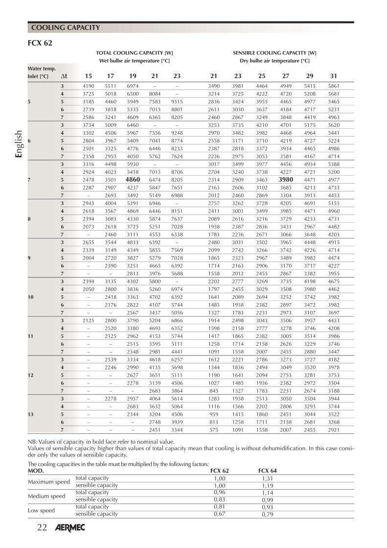
FCX 62 TOTAL COOLING CAPACITY [W] SENSIBLE COOLING CAPACITY [W]
Wet bulbe air temperature [°C] Dry bulbe air temperature [°C]
Water temp.
Inlet [°C] ∆t 15 17 19 21 23 21 23 25 27 29 31 3 4190 5511 6974 – – 3490 3981 4464 4949 5415 5861
4 3725 5018 6500 8084 – 3214 3725 4222 4720 5208 5681
5 5 3185 4460 5949 7583 9315 2836 3424 3955 4465 4977 5465
6 2739 3818 5335 7015 8801 2611 3030 3637 4184 4717 5231
7 2586 3241 4609 6365 8205 2460 2867 3249 3848 4419 4963
3 3734 5009 6460 – – 3253 3735 4210 4701 5175 5620
4 3302 4506 5967 7556 9248 2970 3482 3982 4468 4964 5441
6 5 2804 3967 5409 7041 8774 2558 3171 3710 4219 4727 5224
6 2501 3325 4776 6446 8233 2387 2818 3372 3934 4465 4986
7 2358 2953 4050 5762 7624 2236 2975 3053 3581 4167 4714
3 3316 4498 5930 – – 3017 3499 3977 4456 4934 5388
4 2924 4023 5418 7015 8706 2704 3240 3738 4227 4721 5200
7 5 2478 3501 4860 6474 8205 2314 2909 3463 3980 4471 4977
6 2287 2907 4237 5847 7651 2163 2606 3102 3685 4213 4733
7 – 2693 3492 5149 6988 2012 2460 2869 3304 3913 4453
3 2943 4004 5391 6946 – 2757 3262 3728 4205 4691 5155
4 2618 3567 4869 6446 8151 2411 3001 3499 3985 4471 4960
8 5 2394 3083 4330 5874 7637 2089 2616 3216 3729 4233 4731
6 2073 2618 3725 5251 7028 1938 2387 2836 3431 2967 4482
7 – 2460 3111 4553 6338 1783 2236 2671 3066 3648 4203
3 2655 3544 4833 6392 – 2480 3031 3502 3965 4448 4915
4 2339 3149 4349 5855 7569 2099 2742 3266 3742 4226 4714
9 5 2004 2720 3827 5279 7028 1865 2323 2967 3489 3982 4474
6 – 2390 3251 4665 6392 1714 2163 2906 3170 3717 4227
7 – – 2813 3976 5688 1558 2012 2455 2867 3382 3955
3 2394 3135 4302 5800 – 2202 2777 3269 3735 4198 4675
4 2050 2800 3836 5260 6974 1797 2455 3029 3508 3980 4462
10 5 – 2418 3363 4702 6392 1641 2089 2694 3252 3742 3982
6 – 2176 2822 4107 5744 1485 1938 2382 2897 3472 3982
7 – – 2567 3437 5056 1327 1783 2231 2973 3107 3697
3 2125 2800 3790 5204 6866 1914 2498 3043 3506 3957 4433
4 – 2520 3380 4693 6352 1598 2158 2777 3278 3746 4208
11 5 – 2125 2962 4153 5744 1417 1865 2382 3005 3514 3986
6 – – 2515 3595 5111 1258 1714 2158 2626 3229 3746
7 – – 2348 2981 4441 1091 1558 2007 2455 2880 3447
3 – 2539 3334 4618 6257 1612 2221 2786 3273 3727 4182
4 – 2246 2990 4135 5698 1344 1836 2494 3049 3520 3978
12 5 – – 2627 3651 5111 1190 1641 2094 2753 3281 3753
6 – – 2278 3139 4506 1027 1485 1936 2382 2972 3504
7 – – – 2683 3864 845 1327 1783 2231 2674 3188
3 – 2278 2957 4064 5614 1283 1938 2513 3050 3504 3944
4 – – 2683 3632 5064 1116 1566 2202 2806 3293 3744
13 5 – – 2344 3204 4506 959 1415 1860 2451 3044 3522
6 – – – 2748 3939 813 1258 1711 2158 2681 3268
7 – – – 2451 3344 575 1091 1558 2007 2455 2921
NB: Values of capacity in bold face refer to nominal value.Values of sensible capacity higher than values of total capacity mean that cooling is without dehumidification. In this case consi-der only the values of sensible capacity.
The cooling capacities in the table must be multiplied by the following factors: MOD. FCX 62 FCX 64
Maximum speed total capacity 1,00 1,31
sensible capacity 1,00 1,19
Medium speed total capacity 0,96 1,14
sensible capacity 0,83 0,99
Low speed total capacity 0,81 0,93
sensible capacity 0,67 0,79
23
Engl
ish
COOLING CAPACITY
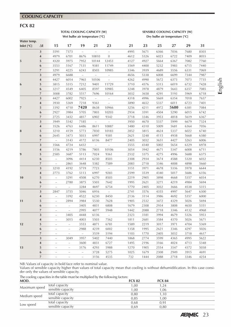
FCX 82
The cooling capacities in the table must be multiplied by the following factors: MOD. FCX 82 FCX 84
Maximum speed total capacity 1,00 1,24
sensible capacity 1,00 1,06
Medium speed total capacity 0,80 1,10
sensible capacity 0,85 1,00
Low speed total capacity 0,68 0,91
sensible capacity 0,69 0,80
TOTAL COOLING CAPACITY [W] SENSIBLE COOLING CAPACITY [W]
Wet bulbe air temperature [°C] Dry bulbe air temperature [°C]
Water temp.
Inlet [°C] ∆t 15 17 19 21 23 21 23 25 27 29 31 3 5591 7373 – – – 4995 5671 6366 7036 7680 8303
4 4979 6701 8676 10810 0 4612 5326 6023 6722 7409 8055
5 5 4320 5975 7952 10144 12453 4127 4927 5664 6367 7082 7760
6 3553 5167 7131 9381 11749 3569 4400 5232 5983 6715 7440
7 3291 4225 6243 8503 10985 3346 3939 4689 5556 6331 7069
3 4979 6688 – – – 4656 5338 6008 6699 7344 7987
4 4427 6014 7965 10106 – 4262 4990 5672 6373 7073 7735
6 5 3815 5315 7212 9401 11729 3710 4576 5313 6019 6732 7428
6 3217 4549 6405 8597 10985 3248 3978 4879 5643 6357 7085
7 3008 3782 5517 7696 10164 3032 3658 4291 5193 5969 6718
3 4427 6002 7925 – – 4318 4996 5669 6354 7018 7657
4 3930 5369 7218 9361 – 3890 4652 5337 6011 6723 7401
7 5 3392 4710 7420 8638 10966 3256 4211 4972 5680 6381 7084
6 2927 3984 5705 7803 10203 2934 3591 4504 5290 6015 6742
7 2725 3432 4817 6902 9342 2718 3346 3953 4818 5619 6367
3 3949 5342 7185 – – 3950 4670 5337 5999 6679 7324
4 3526 4763 6486 8611 10887 3480 4310 5009 5681 6364 7056
8 5 3210 4159 5773 7830 10183 2852 3815 4624 5337 6022 6740
6 2645 3473 5033 6997 9381 2621 3248 4115 4938 5668 6380
7 – 3143 4172 6136 8477 2405 3032 3651 4427 5263 6006
3 3566 4724 6432 – – 3555 4340 5002 5654 6329 6978
4 3156 4219 5786 7803 10106 3054 3942 4671 5347 6008 6711
9 5 2585 3687 5113 7024 9361 2532 3375 4275 4996 5688 6375
6 – 3096 4414 6230 8503 2308 2934 3674 4588 5320 6032
7 – 2861 3648 5382 7589 2083 2718 3346 4008 4898 5660
3 3210 4192 5719 7723 – 3151 3971 4678 5336 5978 6644
4 2773 3762 5113 6997 9283 2599 3539 4340 5017 5686 6356
10 5 – 3291 4508 6270 8503 2219 2905 3898 4668 5357 6034
6 – 2780 3875 5503 7642 1995 2621 3271 4219 4984 5694
7 – – 3284 4697 6754 1770 2405 3032 3666 4538 5315
3 2847 3755 5046 6916 – 2741 3576 4355 4997 5647 6300
4 – 3392 4522 6230 8450 2136 3114 3986 4692 5357 6000
11 5 – 2894 3984 5530 7628 1905 2532 3472 4329 5026 5694
6 – – 3405 4831 6808 1679 2308 2934 3808 4650 5351
7 – – 2995 4077 5948 1442 2088 2718 3346 4132 4968
3 – 3405 4448 6136 – 2323 3181 3994 4679 5326 5953
4 – 3015 4003 5503 7562 1811 2681 3584 4370 5026 5671
12 5 – – 3553 4871 6781 1589 2219 3017 3971 4704 5369
6 – – 2988 4239 6002 1358 1995 2621 3346 4297 5026
7 – – – 3539 5194 1103 1770 2405 3032 3718 4617
3 – 3049 3957 5402 7440 1868 2774 3599 4365 4995 5622
4 – – 3600 4831 6727 1495 2196 3166 4024 4713 5348
13 5 – – 3176 4293 5988 1270 1905 2554 3547 4372 5038
6 – – – 3728 5275 1025 1679 2308 2949 3915 4691
7 – – – 3156 4535 732 1444 2088 2718 3346 4254
NB: Values of capacity in bold face refer to nominal value.Values of sensible capacity higher than values of total capacity mean that cooling is without dehumidification. In this case consi-der only the values of sensible capacity.

24
Engl
ish
COOLING CAPACITY
FCX 102 TOTAL COOLING CAPACITY [W] SENSIBLE COOLING CAPACITY [W]
Wet bulbe air temperature [°C] Dry bulbe air temperature [°C]
Water temp.
Inlet [°C] ∆t 15 17 19 21 23 21 23 25 27 29 31 3 6495 – – – – 5223 5958 6664 7366 – –
4 5846 7808 10067 – – 4880 5605 6333 7080 7784 8471
5 5 5153 7043 9291 11788 – 4441 5230 5974 6715 7473 8200
6 4403 6221 8428 10970 13656 3828 4778 5582 6348 7105 7863
7 3609 5326 7519 10025 12816 3308 4140 5122 5940 6716 7501
3 5802 – – – – 4881 5588 6294 7003 – –
4 5196 7029 9249 – – 4521 5248 5963 6693 7426 8107
6 5 4576 6293 8457 10928 – 4063 4866 5607 6352 7094 7835
6 3869 5514 7591 10067 12795 3330 4399 5208 5971 6717 7489
7 3263 4648 6697 9120 11914 2985 3696 4725 5562 6347 7120
3 5153 6956 – – – 4537 5227 5932 6630 7337 –
4 4612 6278 8413 – – 4151 4900 5610 6329 7056 7754
7 5 4057 5586 7620 10046 12711 3608 4503 5249 5980 6715 7460
6 3379 4865 6798 9149 11893 2912 3978 4847 5608 6357 7117
7 2953 4028 5918 8226 10970 2670 3315 4315 5195 5969 6734
3 4569 6206 – – – 4158 4886 5581 6264 6968 7659
4 4122 5571 7562 9962 – 3726 4554 5261 5964 6687 7390
8 5 3609 4937 6812 9120 11809 3139 4124 4898 5623 6339 7087
6 2903 4273 6033 8255 10928 2582 3491 4481 5255 5991 6727
7 – 3508 5196 7360 9962 2348 2985 3843 4820 5618 6373
3 4114 5485 7447 – – 3748 4551 5223 5913 6598 7297
4 3703 4937 6754 9063 – 3293 4195 4921 5614 6295 7027
9 5 3162 4381 6033 8226 10865 2626 3696 4554 5273 5988 6707
6 – 3783 5312 7389 9941 2264 2978 4084 4901 5631 6362
7 – 3119 4547 6524 9005 2033 2670 3374 4432 5247 5996
3 3710 4850 6639 – – 3330 4180 4888 5574 6231 6935
4 3278 4388 5990 8139 – 2846 3770 4575 5265 5951 6652
10 5 – 3912 5341 7360 9878 2176 3242 4183 4927 5628 6334
6 – 3306 4677 6552 8976 1945 2582 3623 4548 5278 5999
7 – – 3956 5730 8053 1706 2352 2993 4015 4896 5638
3 3299 4331 5860 – – 2905 3770 4559 5217 5878 6563
4 – 3956 5283 7274 9753 2370 3345 4224 4928 5609 6278
11 5 – 3480 4713 6524 8890 1857 2751 3770 4594 5288 5976
6 – – 4129 5773 8024 1621 2264 3125 4171 4943 5646
7 – – 3451 5023 7129 1379 2033 2670 3506 4525 5293
3 – 3927 5153 7101 – 2472 3352 4195 4889 5559 6189
4 – 3537 4677 6423 8760 1820 2905 3806 4598 5270 5930
12 5 – – 4194 5745 7937 1536 2209 3315 4239 4947 5632
6 – – 3667 5081 7101 1298 1945 2612 3733 4595 5302
7 – – – 4388 6264 1037 1709 2355 3029 4134 4937
3 – 3523 4569 6264 – 2025 2934 3784 4571 5203 5845
4 – – 4186 5644 7822 1447 2436 3381 4253 4936 5595
13 5 – – 3761 5052 7029 1213 1857 2846 3828 4623 5295
6 – – – 4475 6249 962 1621 2264 3257 4229 4968
7 – – – 3862 5485 662 1381 2033 2670 3667 4589
NB: Values of capacity in bold face refer to nominal value.Values of sensible capacity higher than values of total capacity mean that cooling is without dehumidification. In this case consi-der only the values of sensible capacity.
The cooling capacities in the table must be multiplied by the following factors:MOD. FCX 102
Maximum speed total capacity 1,00
sensible capacity 1,00
Medium speed total capacity 0,94
sensible capacity 0,90
Low speed total capacity 0,82
sensible capacity 0,77
25
Engl
ish
� ��� � ��� � ��� � ��� � ������
���
���
���
���
���
��
�� �� ���� � ��
Wat
er fl
ow r
ate
[l/h
]
∆t °C (temperature entering water - temperature entering air)
Heating capacity [kW]
FCX 22
��� � ��� � ��� � ��� � ��� �� � ������
���
���
���
���
���
��
�� �� ���� � ��
Wat
er fl
ow r
ate
[l/h
]
∆t °C (temperature entering water - temperature entering air)
Heating capacity [kW]
FCX 32
���
���
���
��
���
��
� � � � � � �� ��
���� �� �� ���� � ��
Wat
er fl
ow r
ate
[l/h
]∆t °C (temperature entering water - temperature entering air)
Heating capacity [kW]
FCX 42
� � � � � � �� �� �� ��
�� �� ���� � ��
���
���
���
��
���
��
����
Wat
er fl
ow r
ate
[l/h
]
∆t °C (temperature entering water - temperature entering air)
Heating capacity [kW]
FCX 50
���
���
��
����
����
����
����
���
����
� � �� � ��
�� �� �� �� � ��
Wat
er fl
ow r
ate
[l/h
)
∆t °C (temperature entering water - temperature entering air)
Heating capacity [kW]
FCX 62
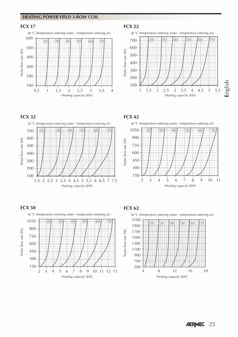
HEATING POWER YIELD 3-ROW COIL
���
���
���
���
���
��
��� � ��� � ��� � ��� �
�� �� ���� � ��
Wat
er fl
ow r
ate
[l/h
]
∆t °C (temperature entering water - temperature entering air)
Heating capacity [kW]
FCX 17

26
Engl
ish
HEATING POWER YIELD 3-ROW COIL
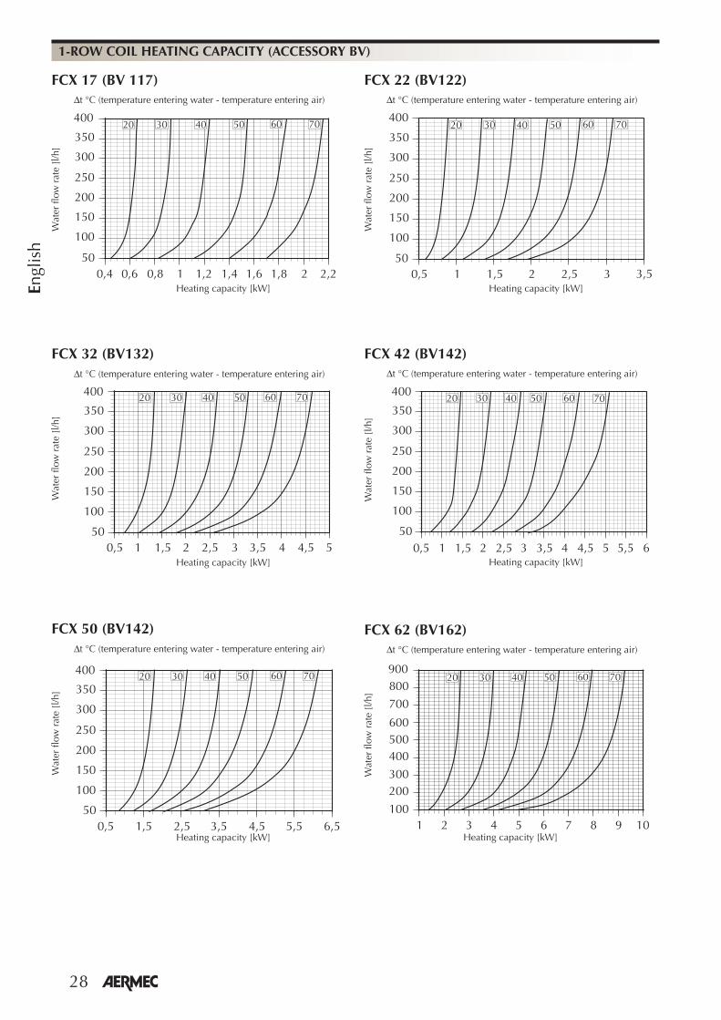
HEATING CAPACITY CORRECTION FACTORS
The heating capacities are at maximum speed. For the other speeds, the values must be multiplied by the following factors:
MOD. FCX17 FCX 22 FCX 32 FCX 42 FCX 50 FCX 62 FCX 82 FCX102Medium speed 0,83 0,79 0,82 0,87 0,87 0,85 0,88 0,90Low speed 0,65 0,56 0,68 0,69 0,63 0,64 0,71 0,74
� � �� �� �� � �� �����
��
��
����
����
����
�� �� ���� � ������
��
Wat
er fl
ow r
ate
(l/h)
∆t °C (temperature entering water - temperature entering air)
Heating capacity [kW]
FCX 82
��
���
����
����
����
���
����
����
����
� � �� �� �� �� � �� �� ��
Wat
er fl
ow r
ate
(l/h]
∆t °C (temperature entering water - temperature entering air)
Heating capacity [kW]
FCX 102

27
Engl
ish���
���
���
���
���
��
���
� � � � � � � �
�� �� ���� � ��
Wat
er fl
ow r
ate
[l/h
]
∆t °C (temperature entering water - temperature entering air)
Heating capacity [kW]
FCX 34
���
���
��
���
����
� � � � �� �� ��
�� �� ���� � ��
Wat
er fl
ow r
ate
[l/h
]
∆t °C (temperature entering water - temperature entering air)
Heating capacity [kW]
FCX 44
���
���
���
���
���
��
���
���
��
����
� � � �� �� �� ��
�� �� ���� � ��
Wat
er fl
ow r
ate
[l/h
]∆t °C (temperature entering water - temperature entering air)
Heating capacity [kW]
FCX 54
���
���
���
��
����
����
��������
�������
� � �� �� �� ��
�� �� ���� � ��
Wat
er fl
ow r
ate
[l/h
]
∆t °C (temperature entering water - temperature entering air)
Heating capacity [kW]
FCX 64
���
���
���
��
����
����
����
����
���
����
� � �� �� �� �� ��
�� �� ���� � ��
Wat
er fl
ow r
ate
[l/h
]
∆t °C (temperature entering water - temperature entering air)
Heating capacity [kW]
FCX 84
HEATING POWER YIELD 4-ROW COIL
���
���
���
���
���
��
���
� � � � � � �
�� �� ���� � ��
Wat
er fl
ow r
ate
[l/h
]
∆t °C (temperature entering water - temperature entering air)
Heating capacity [kW]
FCX 24
HEATING CAPACITY CORRECTION FACTORS
The heating capacities are at maximum speed. For the other speeds, the values must be multiplied by the following factors:
MOD. FCX 24 FCX 34 FCX 44 FCX 54 FCX 64 FCX 84Medium speed 0,81 0,83 0,81 0,87 0,80 0,84Low speed 0,56 0,66 0,60 0,62 0,59 0,65
28
Engl
ish
�� �� �� �� � ��
��� ��� ��� ��������
���
���
���
���
���
���
���
Wat
er fl
ow r
ate
[l/h
]
∆t °C (temperature entering water - temperature entering air)
Heating capacity [kW]
FCX 22 (BV122)
��
���
���
���
��� �� �� �� �� � ��
���
���
���
��� ��� ��� ��� ��� �����
Wat
er fl
ow r
ate
[l/h
]
∆t °C (temperature entering water - temperature entering air)
Heating capacity [kW]
FCX 32 (BV132)
�� �� �� �� � ��
��� ��� ��� ��� ��� ��� � ������
���
���
���
���
���
���
���
Wat
er fl
ow r
ate
[l/h
]∆t °C (temperature entering water - temperature entering air)
Heating capacity [kW]
FCX 42 (BV142)
��
���
���
���
���
��� ��� ��� ��� ��� ��� ��
�� �� �� �� � ��
���
���
���
Wat
er fl
ow r
ate
[l/h
]
∆t °C (temperature entering water - temperature entering air)
Heating capacity [kW]
FCX 50 (BV142)
� � � � � � � ��
�� �� �� �� � ��
���
������
���
��
��
���
������
Wat
er fl
ow r
ate
[l/h
]
∆t °C (temperature entering water - temperature entering air)
Heating capacity [kW]
FCX 62 (BV162)
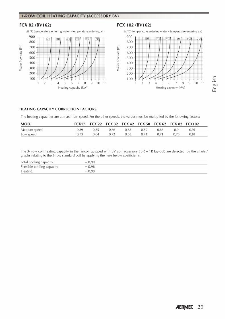
1-ROW COIL HEATING CAPACITY (ACCESSORY BV)
�� �� �� �� � ��
��� ��� ��� �� � ��������������
���
���
���
���
���
���
���
Wat
er fl
ow r
ate
[l/h
]
∆t °C (temperature entering water - temperature entering air)
Heating capacity [kW]
FCX 17 (BV 117)
29
Engl
ish
1-ROW COIL HEATING CAPACITY (ACCESSORY BV)
HEATING CAPACITY CORRECTION FACTORS
The heating capacities are at maximum speed. For the other speeds, the values must be multiplied by the following factors:
MOD. FCX17 FCX 22 FCX 32 FCX 42 FCX 50 FCX 62 FCX 82 FCX102Medium speed 0,89 0,85 0,86 0,88 0,89 0,86 0,9 0,91Low speed 0,73 0,64 0,72 0,68 0,74 0,71 0,76 0,81
The 3- row coil heating capacity in the fancoil quipped with BV coil accessory ( 3R + 1R lay-out) are detected by the charts / graphs relating to the 3-row standard coil by applying the here below coefficients.
Total cooling capacity = 0,99Sensible cooling capacity = 0,98Heating = 0,99
���
������
���
��
��
� � � � � � � ��
�� �� �� �� � ��
���
������
��
Wat
er fl
ow r
ate
[l/h
]
∆t °C (temperature entering water - temperature entering air)
Heating capacity [kW]
FCX 82 (BV162)
���
������
���
��
��
� � � � � � � ��
�� �� �� �� � ��
���
������
��
Wat
er fl
ow r
ate
[l/h
]
∆t °C (temperature entering water - temperature entering air)
Heating capacity [kW]
FCX 102 (BV162)
30
Engl
ish
���
���
�� �� � �� ��
� ��
���
���
���
���
���
��
���
���
���
�� �� �� �� �
���
��
�
��
wet bulb temperature intake air [°C] wet bulb temperature intake air [°C]
Coo
ling
capa
city
[kW
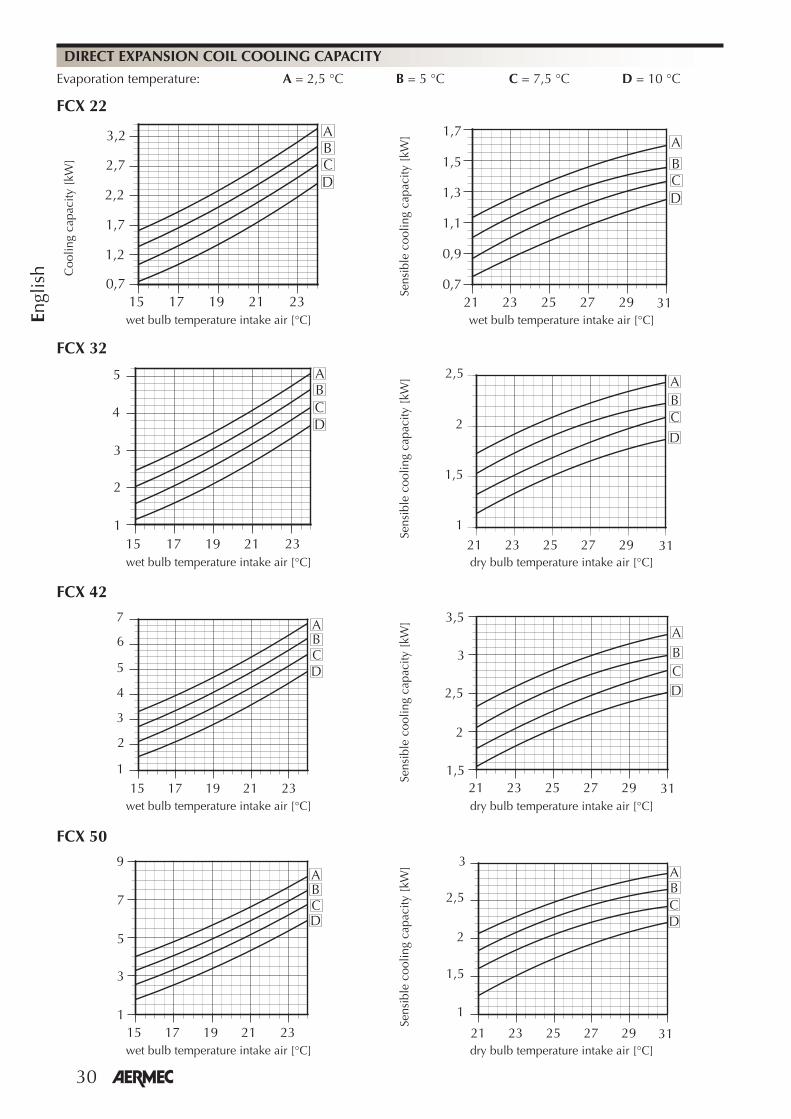
]Evaporation temperature: A = 2,5 °C B = 5 °C C = 7,5 °C D = 10 °C
DIRECT EXPANSION COIL COOLING CAPACITY
FCX 22
Sens
ible
coo
ling
capa
city
[kW
]
�
�
�
�
�� �� � ��
�
��
� ��
�
���
�
�� �� �� �� �
���
��
� �
�
wet bulb temperature intake air [°C] dry bulb temperature intake air [°C]
FCX 32
Sens
ible
coo
ling
capa
city
[kW
]
�
�
�
�
�
�
�� �� � �� ��
� ��
���
�
���
�� �� �� �� �
���
��
� ��
�
wet bulb temperature intake air [°C] dry bulb temperature intake air [°C]
FCX 42
Sens
ible
coo
ling
capa
city
[kW
]
�
�
�
�
�� �� � �� ��
� ��
�
���
�
���
�� �� �� �� �
�
��
� ��
wet bulb temperature intake air [°C] dry bulb temperature intake air [°C]
FCX 50
Sens
ible
coo
ling
capa
city
[kW
]
31
Engl
ish
�
�
�
��
��
�� �� � �� ��
� ��
�
�
�
�
�� �� �� �� �
��
� ��
wet bulb temperature intake air [°C] wet bulb temperature intake air [°C]
Coo
ling
capa
city
[kW
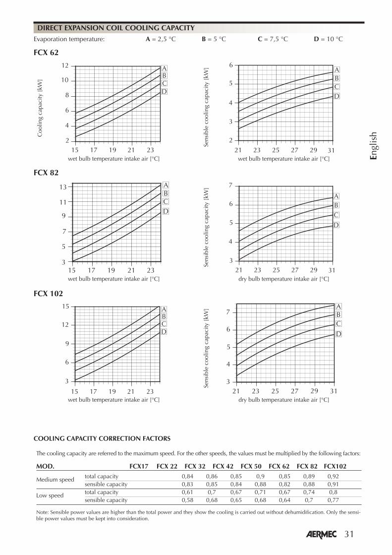
]Evaporation temperature: A = 2,5 °C B = 5 °C C = 7,5 °C D = 10 °C
DIRECT EXPANSION COIL COOLING CAPACITY
FCX 62
Sens
ible
coo
ling
capa
city
[kW
]
�
�
�
��
��
�� �� � �� ��
� ��
�
�
�
�� �� �� �� �
�
��
� �
�
wet bulb temperature intake air [°C] dry bulb temperature intake air [°C]
FCX 82
Sens
ible
coo
ling
capa
city
[kW
]
�
��
��
�� �� � �� ��
� ��
�
�
�
�
�� �� �� �� ��
� �
�
�wet bulb temperature intake air [°C] dry bulb temperature intake air [°C]
FCX 102
Sens
ible
coo
ling
capa
city
[kW
]
COOLING CAPACITY CORRECTION FACTORS
The cooling capacity are referred to the maximum speed. For the other speeds, the values must be multiplied by the following factors:
MOD. FCX17 FCX 22 FCX 32 FCX 42 FCX 50 FCX 62 FCX 82 FCX102
Medium speed total capacity 0,84 0,86 0,85 0,9 0,85 0,89 0,92 sensible capacity 0,83 0,85 0,84 0,88 0,82 0,88 0,91
Low speed total capacity 0,61 0,7 0,67 0,71 0,67 0,74 0,8 sensible capacity 0,58 0,68 0,65 0,68 0,64 0,7 0,77
Note: Sensible power values are higher than the total power and they show the cooling is carried out without dehumidification. Only the sensi-ble power values must be kept into consideration.
32
Engl
ish
�
��
��
��
�
��� ��� ��� ��� ��� ��� ��� ��� �� ��� ��
��
��
��
����
�
��
Air flow rate [m3/h]
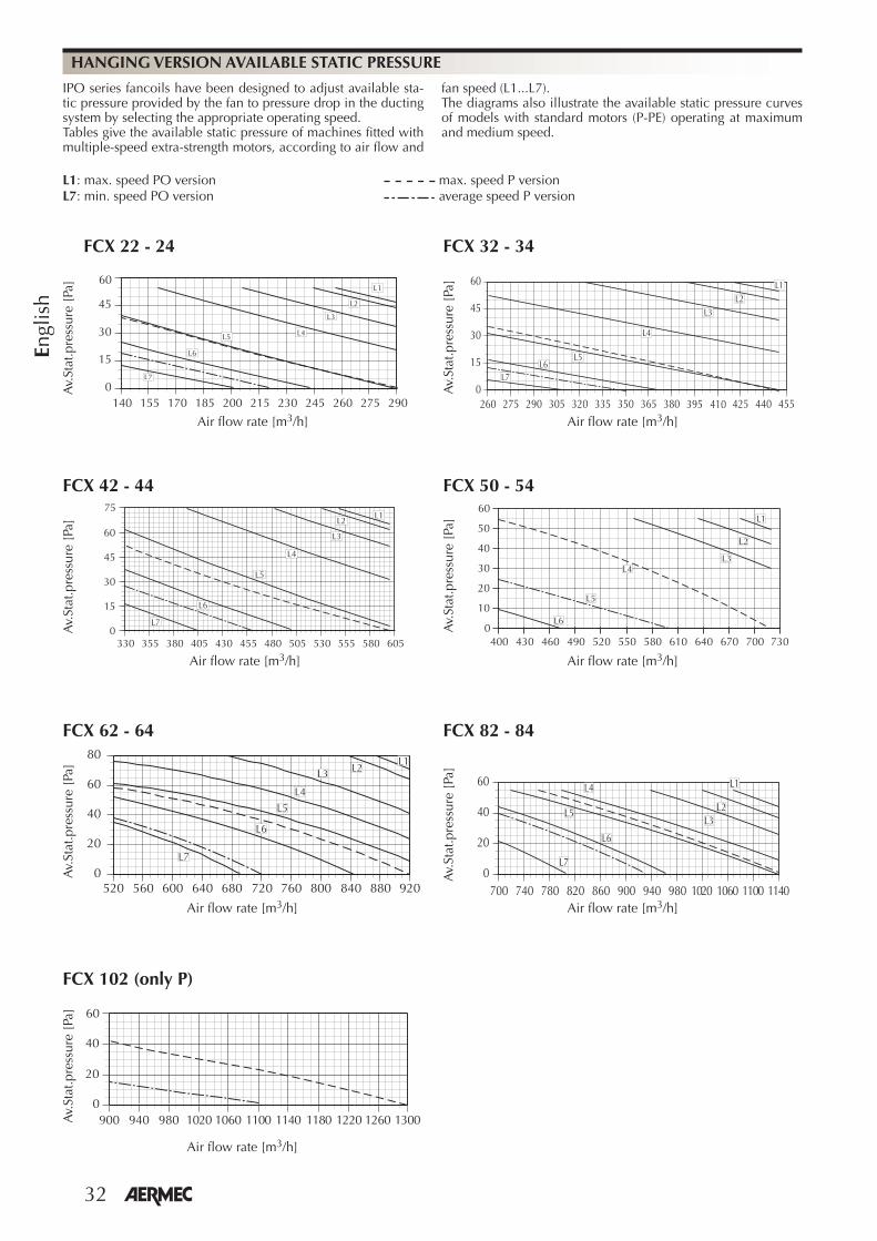
IPO series fancoils have been designed to adjust available sta-tic pressure provided by the fan to pressure drop in the ducting system by selecting the appropriate operating speed.Tables give the available static pressure of machines fitted with multiple-speed extra-strength motors, according to air flow and
fan speed (L1...L7).The diagrams also illustrate the available static pressure curves of models with standard motors (P-PE) operating at maximum and medium speed.
L1: max. speed PO version max. speed P versionL7: min. speed PO version average speed P version
Av.
Stat
.pre
ssur
e [P
a]
HANGING VERSION AVAILABLE STATIC PRESSURE
FCX 22 - 24
�
��
��
��
�
�� ��� �� ��� ��� ��� ��� �� ��� �� ��� ��� ��� ���
����
��
��
���
��
Air flow rate [m3/h]
Av.
Stat
.pre
ssur
e [P
a]
FCX 32 - 34
�
��
��
��
�
��
��� ��� ��� ��� ��� ��� ��� ��� ��� ��� ��� ��
����
��
��
��
�
��
Air flow rate [m3/h]
Av.
Stat
.pre
ssur
e [P
a]
FCX 42 - 44
�
��
��
��
��
��
�
��� ��� �� �� ��� ��� ��� �� �� �� ��� ���
��
��
��
��
��
�
Air flow rate [m3/h]
Av.
Stat
.pre
ssur
e [P
a]
FCX 50 - 54
�
��
��
�
��
��� �� �� �� �� ��� �� ��� ��� ��� ��
����
��
��
��
�
��
Air flow rate [m3/h]
Av.
Stat
.pre
ssur
e [P
a]
FCX 62 - 64
�
��
��
�
��� ��� ��� ��� �� �� �� �� ���� ��� ���� ����
��
����
��
��
�
��
Air flow rate [m3/h]
Av.
Stat
.pre
ssur
e [P
a]
FCX 82 - 84
�
��
��
�
�� �� �� ���� ��� ���� ���� ���� ���� ��� ����
Air flow rate [m3/h]
Av.
Stat
.pre
ssur
e [P
a]
FCX 102 (only P)
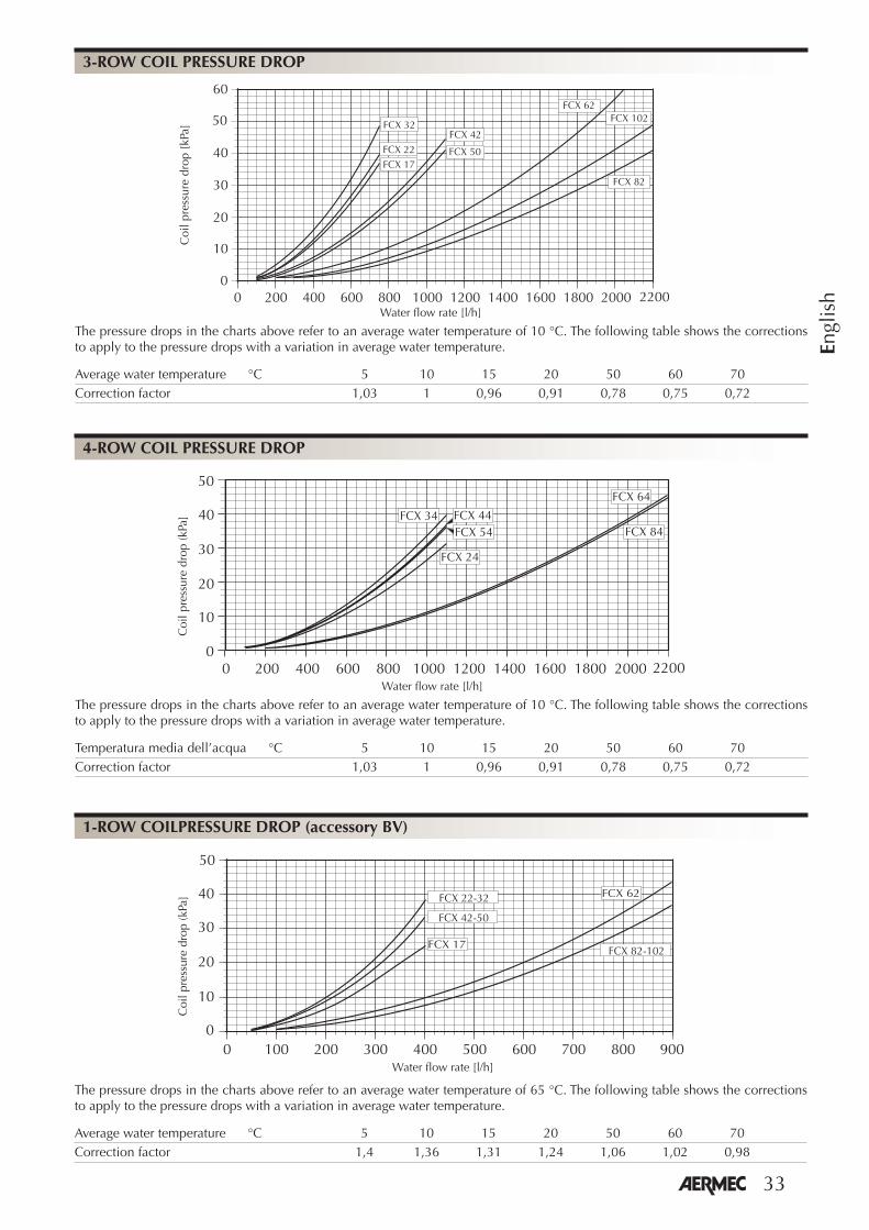
33
Engl
ish
� ��� ��� �� ��� ���� ���� ���� ��� ���� ���� �����
��
��
��
��
��
������ ������������
������
�����
������
�
��
��
��
��
��
� ��� ��� ��� ��� ��� �� ��� ��� ��
����������
�����
������
���������
���������
�
��
��
��
��
��
� ��� ��� �� ��� ���� ���� ���� ��� ���� ����
�
����
������
�����
������
������
������
�������
������������
Water flow rate [l/h]
Coi
l pre
ssur
e dr
op [
kPa]
3-ROW COIL PRESSURE DROP
The pressure drops in the charts above refer to an average water temperature of 10 °C. The following table shows the corrections to apply to the pressure drops with a variation in average water temperature.
Average water temperature °C 5 10 15 20 50 60 70Correction factor 1,03 1 0,96 0,91 0,78 0,75 0,72
4-ROW COIL PRESSURE DROP
Water flow rate [l/h]
Coi
l pre
ssur
e dr
op (k
Pa]
The pressure drops in the charts above refer to an average water temperature of 10 °C. The following table shows the corrections to apply to the pressure drops with a variation in average water temperature.
Temperatura media dell’acqua °C 5 10 15 20 50 60 70Correction factor 1,03 1 0,96 0,91 0,78 0,75 0,72
1-ROW COILPRESSURE DROP (accessory BV)
The pressure drops in the charts above refer to an average water temperature of 65 °C. The following table shows the corrections to apply to the pressure drops with a variation in average water temperature.
Average water temperature °C 5 10 15 20 50 60 70Correction factor 1,4 1,36 1,31 1,24 1,06 1,02 0,98
Water flow rate [l/h]
Coi
l pre
ssur
e dr
op (k
Pa]
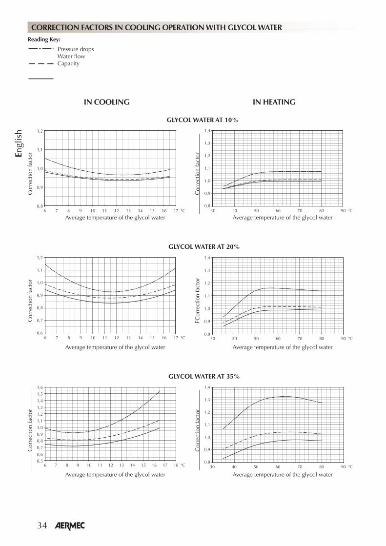
34
Engl
ish
���
��
���
���
���
� � �� �� �� �� �� �� � ������
Average temperature of the glycol water
Cor
rect
ion
fact
or
Pressure dropsWater flow Capacity
GLYCOL WATER AT 10%
GLYCOL WATER AT 35%
GLYCOL WATER AT 20%
CORRECTION FACTORS IN COOLING OPERATION WITH GLYCOL WATER
IN COOLING IN HEATING
��
���
���
��
���
���
���
� � �� �� �� �� �� �� � ������
Average temperature of the glycol water
Cor
rect
ion
fact
or
���
��
���
���
��
���
���
���
���
���
���
��
� � �� �� �� �� �� �� � �� ������
Average temperature of the glycol water
Cor
rect
ion
fact
or
�� �� �� � �� �� ��������
��
���
���
���
���
���
Average temperature of the glycol water
Cor
rect
ion
fact
or
���
��
���
���
���
���
���
�� �� �� � �� �� �����
Average temperature of the glycol water
FCor
rect
ion
fact
or
���
��
���
���
���
���
���
�� �� �� � �� �� �����
Average temperature of the glycol water
Cor
rect
ion
fact
or
Reading Key:

35
Engl
ish
Sound pressure level (weighted A) measured in a room with 85 m3 volume , reverberation time t= 0,5 s , direction.factor Q= 2 , distance r= 2,5m .
Speed Band middle frequency [Hz] GlobalMod. 125 250 500 1000 2000 4000 8000 dB dB (A) Max 40,4 45,8 43,4 39,7 36,2 28,3 14,8 49,3 45 (E)FCX17 Med. 34,1 40,2 36,7 32,6 26,9 21,1 4,0 43,0 38 (E) Min 26,1 33,0 29,2 26,1 19,7 16,2 4,1 35,8 31 (E)
Max. 45,6 50,6 48,4 44,7 41,3 33,3 19,7 54,2 50 (E)FCX22 Med. 39,2 44,9 41,7 37,6 31,9 25,8 7,5 47,9 43 (E) Min. 25,8 33,0 29,1 26,2 19,9 16,2 2,6 35,7 31 (E)
Max. 43,6 48,8 46,4 42,7 39,0 31,3 17,7 52,3 48 (E)FCX32 Med. 37,0 43,0 39,7 35,7 29,9 24,0 5,4 45,9 41 (E) Min. 28,9 36,1 32,2 29,0 22,9 19,2 3,1 38,8 34 (E)
Max. 46,6 51,8 49,4 45,7 42,0 34,3 20,7 55,3 51 (E)FCX42 Med. 39,6 44,8 42,4 38,7 35,0 27,3 13,7 48,3 44 (E) Min. 31,9 39,1 35,2 32,0 25,9 22,2 6,1 41,8 37 (E)
Max. 51,6 56,8 54,4 50,7 47,0 39,3 25,7 60,3 56 (E)FCX50 Med. 46,6 51,8 49,4 45,7 42,0 34,3 20,7 55,3 51 (E) Min. 37,6 42,8 40,4 36,7 33,0 25,3 11,7 46,3 42 (E)
Max. 52,6 57,5 55,4 51,7 48,3 40,3 26,7 61,2 57 (E)FCX62 Med. 46,4 51,8 49,6 45,7 41,9 34,3 20,8 55,3 51 (E) Min. 37,7 42,6 40,4 36,8 33,0 25,3 11,7 46,3 42 (E)
Max. 57,6 62,8 60,5 56,7 53,2 45,0 31,8 66,3 62 (E)FCX82 Med. 52,4 57,8 55,5 51,7 48,2 40,1 26,7 61,3 57 (E) Min. 45,6 51,0 48,4 44,6 41,1 33,2 19,8 54,4 50 (E)
Max. 61,5 66,7 64,4 60,7 57,1 49,3 35,8 70,3 66 (E)FCX102 Med. 56,6 61,8 59,4 55,7 52,0 44,3 30,7 65,3 61 (E) Min. 51,7 56,8 54,4 50,7 46,9 39,3 25,7 60,3 56 (E)
Speed Mod. FCX 17 22 32 42 50 62 82 102 Max 36,5 41,5 39,5 42,5 47,5 48,5 53,5 57,5 Med. 29,5 34,5 32,5 35,5 42,5 42,5 48,5 52,5 Min 22,5 22,5 25,5 28,5 33,5 33,5 41,5 47,5
(E) = EUROVENT certified performance.
SOUND PRESSURE LEVEL RATED IN DB (A)
SOUND POWER LEVEL RATED IN dB (A)

36
Engl
ish
Sound pressure level (weighted A) measured in a room with 85 m3 volume , reverberation time t= 0,5 s , direction.factor Q= 2 , distance r= 2,5m .
Speed Band middle frequency [Hz] GlobalMod. 125 250 500 1000 2000 4000 8000 dB dB (A) Max. 46,5 51,6 49,3 45,7 42,3 34,3 20,8 54,2 51FCX24 Med. 42,0 47,9 44,8 40,6 34,8 28,8 10,5 47,9 46 Min. 29,8 37,2 33,1 30,0 23,8 20,2 5,1 35,7 35 Max. 43,7 48,8 46,5 42,7 39,1 31,3 17,6 52,3 48FCX34 Med. 37,2 42,5 40,0 35,7 29,9 24,2 6,1 45,9 41 Min. 30,8 38,0 34,2 31,1 24,9 21,2 5,7 38,8 36 Max. 50,4 55,8 53,7 49,3 46,0 38,5 24,7 55,3 55FCX44 Med. 45,9 50,6 48,4 44,6 41,3 33,3 20,0 48,3 50 Min. 36,2 42,5 39,4 36,2 29,8 26,2 9,9 41,8 41 Max. 51,8 56,8 54,2 50,7 47,3 39,2 25,5 60,3 56FCX54 Med. 48,5 53,8 51,2 47,7 44,3 36,4 22,8 55,3 53 Min. 40,0 44,8 42,3 38,7 35,2 27,3 13,9 46,3 44 Max. 52,3 57,6 55,4 51,7 48,3 41,1 26,5 61,2 57FCX64 Med. 46,5 52,0 49,6 45,7 41,7 34,3 20,6 55,3 51 Min. 39,6 44,5 42,4 39,1 34,8 27,9 13,7 46,3 44 Max. 56,8 61,8 59,4 55,7 52,0 44,3 30,9 66,3 61FCX84 Med. 52,5 57,7 55,5 51,7 48,2 40,3 26,6 61,3 57 Min. 46,7 52,3 49,6 45,2 42,1 34,5 21,2 54,4 51
Velocità Mod. FCX 24 34 44 54 64 84 Max. 42,5 39,5 46,5 47,5 48,5 52,5 Med. 37,5 32,5 41,5 44,5 42,5 48,5 Min. 26,5 27,5 32,5 35,5 35,5 42,5
SOUND PRESSURE LEVEL RATED IN dB (A)
SOUND POWER LEVEL RATED IN DB (A)

37
Engl
ish
The sound power level generated by ducted fancoils (FCX -PO) depends on fan speed and on the point of operation reached according to pressure drop.
The following diagrams can be used to obtain the sound power level (weighted A), expressed in dB (A) in relation to the rele-vant curve, according to air flow and available static pressure values.
FCX-PO SOUND POWER LEVELS OF DUCTED HANGING VERSIONS in dB
�
��
��
��
�
��
�
��� ��� ��� ��� ��� ��� ��� ��� �� ��� ��
�������
��
��
�
��
��
��
��
Air flow rate [m3/h]
The overall sound power level expressed in dB(A) are given for each curve.
Ava
ilabl
e st
atic
pre
ssur
e [P
a]
FCX 22
�
��
��
��
�
��
�
�� ��� �� ��� ��� ��� ��� �� ��� �� ��� ��� ��� ���
��
��
�������
��
��
��
Air flow rate [m3/h]A
vaila
ble
stat
ic p
ress
ure
[Pa]
FCX 32
���
��
��
��
�
��
�
���
���
���
��� ��� ��� ��� ��� ��� ��� ��� ��� ��� ���
�����
��
��
��
�
��
��
Air flow rate [m3/h]
Ava
ilabl
e st
atic
pre
ssur
e [P
a ]
FCX 42
�
��
��
��
�
��
�
��� ��� �� �� ��� ��� ��� �� �� �� ��� ���
�� ����
��
��
�
��
� �
Air flow rate [m3/h]
Ava
ilabl
e st
atic
pre
ssur
e [P
a]
FCX 50
�
��
��
�
��
���
���
���
��� �� �� �� �� ��� �� ��� ��� ��� ��
��
��
�
��
��
����� ��
�
Air flow rate [m3/h]
Ava
ilabl
e st
atic
pre
ssur
e [P
a]
FCX 62
�
��
��
�
��
���
���
��� ��� ��� ��� �� �� �� �� ���� ��� ���� ����
��
���
�
��
��
Air flow rate [m3/h]
Ava
ilabl
e st
atic
pre
ssur
e [P
a]
FCX 82
38
Engl
ish
AMP BRACKETS FOR HANGING UNITSKit includes brackets and bolts for ceiling installation..BC AUXILIARY CONDENSATE DRIP TRAYMade of thermoplastic material, collects the condensate forming in summer operation in the region of the non-insulated hydraulic connections and conveys it to the outside. In particular, the BC4 drip tray must be used on all the sizes with vertical installation of the unit.Attention: The valve VCF and the driptray BC4 can be installed at the same time on the fan coil.Attention: BC8 and BC9 are not applicable to fan coils with cabinet caseThe BC5 drip tray must be installed on sizes FCX 17, 22, 32, 42, 50 and 24, 34, 44, 54 with horizontal installation. The BC6 drip tray must be installed on sizes 62, 82, 102 e 64, 84 with horizontal installation.The BC8 drip tray must be installed on sizes FCX 17, 22, 32, 42, 50 and 24, 34, 44, 54 in version P - PE - PO - POE with horizontal installation. The BC9 drip tray must be installed on sizesFCX 62, 82, 102 and 64, 84 in version P - PE - PO - POE with horizontal installation.BV WATER HEATING COILThe single-row heating coil can be installed in four-tube fancoils above the standard coil.Coil operation is regulated by a control panel, that actuates a twin valveCHF VENTILCASSAFORMAA galvanised template that makes it possible to space to the house fan coils in the wall (FCX P). The template will make masonary work easy during the construction of a niche where the fan coils will be intalled. When work is finished the fan coil will be completely hidden from view.DSC CONDENSATE DRAINAGE DEVICEA pump drains condensate from the unit when natural runoff is not possible. Installed on the exterior of the unitGA INTAKE LOUVREFixed slat sheet metal louvre with stoved polyurethane powder paint finish. The sub-frame is supplied as standardGAF INTAKE LOUVRE WITH FRAME AND FILTERFixed s l a t l ouv re w i th s toved polyurethane powder paint finish; rear side features frame for the filter. The sub-frame and filter are supplied as standard.GM DELIVERY LOUVRELouvre with high-resistance enamel finish; comes with adjustable heat-moulded plastic slats for air diffusion. The subframe is supplied as standard.MA HIGH COVER CABINETConsisting of the cover cabinet, fixed louver and air filter for fan coil in vertical, floor-standing version. The FCX for ceiling installation with the MA cabinet assume the characteristics of the
FCX-AS and can only be fitted with the accessories reserved for this model. BC8 and BC9 are not applicable to fan coils with cabinet case. MU UNIVERSAL COVER CABINETConsisting of the cover cabinet, tiltable (in sizes 17, 22, 32, 42 and 50) or fixed louver (in sizes 62, 82 and 102) and air filter for universal version fan coil (FCX - U). The FCX for ceiling installation with the MU cabinet assume the characteristics of the FCX-US and can only be fitted with the accessories reserved for this model. BC8 and BC9 are not applicable to fan coils with cabinet case.. PA INTAKE PLENUMIn galvanized steel, complete with connections for circular section ducts of diameter 200 mm.There are two assembly positions for the plenum, for intake parallel to the fan coil or intake at 90°.PA FRONT INTAKE PLENUMIn galvanized steel, complete with connections for circular section ducts of diameter 200 mm. The plenum can be used with a front intake coupling parallel to the fan coil delivery or, in sizes PA 32 - 42 - 62 F, also with lateral intake.PC REAR COVER PANELConveniently covers exposed rear fancoil sections.The panel is required by current safety standards for units installed away from the room wall.PCR CONTROL PANEL COVERGalvanised sheet metal cover designed to protect unit controls and electrical terminals of ducted installations with electrical resistance.PM DELIVERY PLENUMGalvanised sheet metal plenum, externally insulated, complete with plastic delivery unions for circular section ducting.RD STRAIGHT CONNECTION FOR AIR DELIVERY Galvanised sheet metal used to convey air in case of installation of vertical or horizontal recessed fan coil.RDA STRAIGHT CONNECTION FOR AIR INTAKE Galvanised sheet metal used to convey intake air in case of installation of vertical or horizontal recessed fan coil.RP CONNECTION AT 90° FOR AIR DELIVERY Galvanised sheet metal used to convey air in case of installation of vertical or horizontal recessed fan coil.RPA CONNECTION AT 90° FOR AIR INTAKE Galvanised sheet metal used to convey intake air in case of installation of vertical or horizontal recessed fan coil.RX ELECTRIC RESISTANCE Armoured electric resistance, complete with safet thermostat. It is available as an accessory for all versions.
SE FRESH AIR DAMPERForeseen for versions A, AS, ACB, ACT, APC, P, PPC, PO and PE with skirting and allows the changing of air in the room. It is mounted at the base of the fan coil, between the skirting. The manual control is loacted on the right skirting.SIT 3Each fan coil has a SIT3 card that becomes Slave and can be controlled by a central control panel with electromechanic selector or with SIT5. Up to 10 fan coils can be applied with SIT 3 and one central control unit. The electronic control panels and those equipped with valve controls must be interfaced with a SIT 5. The electronic control panels with speed control only can be connected directlt to the SIT 3 without interface SIT 5.SIT 5 The SIT 5 accessory, interface master card Master, is connected to electronic control panels or electromechanic control panels with valave controls and /or electric resistances. The SIT 5 interface card connected (up to 10) are all equipped with interface Slave SIT3.SW3 MINIMUM WATER TEMPERATURE PROBEThe SW3 accessory is a probe for detecting the water temperature of the heating coil to prevent functioning when the temperature is less than 39°C. The SW3 probes are powered by a 230V single phase voltage. The probes are equipped with cables 2500mm long.VCF 3 WAY VALVE KITThe SW3 probe must be combined to this accessory.K i t c o m p l e t e w i t h c o p p e r connections and 3 way valves all or nothing type, to be powered by a 230 V ~ 50Hz voltage supply. They are available for fan coils :- with 3 row coil 4 (VCF41, VCF42, VCF43),- with 4 row coil(VCF42, VCF43),- with 1 row additional coil (BV) (VCF44, VCF45).* Attention: The VCF valve and the drip tray BC4 can be installed at the same time as the fan coil.
ZX5 - ZX6 SKIRTING FOR HIGH CABINETIn plastic, mounted at the base of the cabinet when the appliance is placed on the floor.ZX7 - ZX8 SKIRTING FOR WALL VERSIONIn galvanised steel, mounted at the base of the cabinet when the appliance is placed on the floor and recessed into the wall.
ACCESSORIES

39
Engl
ish
CONTROL PANELFMT10 CONTROL PANEL WITH ELECTRONIC THERMOSTAT FOR WALL RECESSINGElectronic thermostat for fan coils instal-led on plants with 4 pipes, 2 pipes and 2 pipes with resistance, with the possibi-lity of connecting 2 On - Off valves for the interception of coil feeding water. Simplified controls with only 2 selec-tor switches for temperature control and fan control (3 speed). External air probe (cable length 6 metres, supplied with the probe-holder) to be positioned inside the fan coil. Recess installation (module 503).For further information refer to the acces-sory instructions.FMT20 CONTROL PANEL WITH ELECTRONIC THERMOSTAT AND LCD FOR WALL RECESSINGElectronic thermostat with LCD for fan coils installed on plants with 4 pipes, 2 pipes and 2 pipes with resistance with the possibility of connecting 2 On - Off valves for the interception of coil fee-ding water. Air temperature probe inside panel. Recess installation (module 503).KTL M REMOTE CONTROL KIT WITH THERMOSTATKit with adjustment thermostat made up from an I.R. remote control, an I.R recei-ver, a circuit board with air temperature probe, the connection cable, brackets and fixing equipment. KTLM can be applied to a fan coil installed in a plant with 2 pipes with or without water valve or with 4 pipes with water valve. For fan coils with cabinet in the FCX series. For further information refer to the acces-sory instructions.KTL P REMOTE CONTROL KIT WITH THERMOSTATKit with adjustment thermostat made up from an I.R. remote control, an I.R recei-ver, a circuit board with air temperature probe, the connection cable, brackets and fixing equipment. can be applied to a fan coil installed in a plant with 2 pipes with or without water valve or with 4 pipes with water valve. For fan coils with cabinet in the FCX series.For further information refer to the acces-sory instructions.PCT2 CONTROL PANEL WITH THERMOSTATControl panel with electro-mechanical thermostat for plants with 2 pipes with ventilation thermostating.PTI MULTI-FUNCTION CONTROL PANEL WITH THERMOSTATElectronic control panel for plants with two pipes, with electronic multi-function thermostat; it has the same functions as the “electronic multi-function thermostat installed in the ACT version”. Installation on board and on wall. For further information refer to the acces-sory instructions.
PX2 CONTROL PANEL WITH SWITCH-OVERControl panel for the manual control of fan speed, made up of an on/off switch-over with 3 positions for the selection of fan speed. Installation on board and on wall. For further information refer to the acces-sory instructions.PXA E CONTROL PANEL WITH ELECTRONIC MULTI-FUNCTION THERMOSTATEltronic multi-function room thermo-stat in plants with two or four pipes. Simplified controls with only two selec-tor switched for control of the temperatu-re and ventilation, 3 speed + automatic speed, on-off and automatic summer/winter switch-over, depending on the temperature of the water. The SW mini-mum water temperature probe is avai-lable as an accessory, which prevents functioning in central heating mode with water temperature below 35°C. Wall installation.For further information refer to the acces-sory instructions.PXA I CONTROL PANEL WITH ELECTRONIC MULTI-FUNCTION THERMOSTATElectronic multi-function room thermo-stat for fan coils in plants with two or four pipes. Simplified controls with only two selector switched for control of the temperature and ventilation, 3 speed + automatic speed, on-off and automa-tic summer/winter switch-over, depen-ding on the temperature of the water. Complete with minimum water tempe-rature probe, which prevents functioning in central heating mode with water tem-perature below 35°C. Installation on board. For further information refer to the acces-sory instructions.PXA R CONTROL PANEL WITH ELECTRONIC MULTI-FUNCTION THERMOSTATElectronic multi-function room thermo-stat for fan coils in plants with two pipes and electric resistance. Simplified con-trols with only two selector switched for control of the temperature and ventila-tion, 3 speed + automatic speed, on-off, activation of the electric resistance when desired and automatic summer/winter switch-over, depending on the tempera-ture of the water. Complete with mini-mum water temperature probe, which prevents functioning in central heating mode with water temperature below 35°C. By means of appropriate confi-guration of the board dip-it can also be used in plants without electric resistance, with two or four pipes. For installation on the machine or wall installation. For further information refer to the acces-sory instructions.PXBI ELECTRONIC CONTROL PANELControl panel with electronic room ther-mostat with simplified functions. It has the same functions as the “Thermostat installed on the ACB version”. The room
temperature probe is positioned inside the thermostat.The thermostat cannot be coupled with a water temperature probe. Installation on board.For further information refer to the acces-sory instructions.PXLM MULTIFUNCTION CONTROL PANELKit for motorization of the fins and con-trol with a control panel. Consists of a control panel with electronic thermostat, a motor to be fitted to the delivery fins, a feed card and probes for detecting water and air temperature.The PXLM controls the operation of a fan coil inserted in a two-pipe hydraulic plant.The control parameters of the electronic panel may be programmed even after installation, simply be pressing the two buttons.Ideally the panel is for wall installation, but can also be fitted on board the unit provided that the ambient probe used is external to the fan coil (excluding that inside the panel) and that suitable corrections are made to the probe cali-bration. For further information, see the instructions coming with the accessory.WMT05 CONTROL PANEL WITH THERMOSTATElectronic thermostat for fan coils instal-led in plants with 2 pipes. The panel is protected electrically by an internal fuse. Wall installation. For further information refer to the accessory instructions.WMT10 CONTROL PANEL WITH THERMOSTATElectro-mechanical thermostat for fan coils installed in plants with 4 pipes, 2 pipes and 2 pipes with resistance, with the possibility to connect two On - Off valves for the interception of coil feeding water.The panel is protected electrically by an internal fuse. Continuous or thermosta-ted ventilation. Wall installation.
ACCESSORIES

40
Engl
ish
Consult the table of compatibility for the selection.
ACCESSORIES
Accessory Fan Coil FCX Size Version
17 22 - 24 32 - 34 42 - 44 50 - 54 62 - 64 82 - 84 102AMP ✔ ✔ ✔ ✔ ✔ ✔ ✔ ✔ P-PPC-PO-PE-U-UE 4 ✔ ✔ ✔ ✔ ✔ ✔ ✔ ✔ all 5 ✔ ✔ ✔ ✔ ✔ P-PPC-PO-PE-U-UEBC 6 ✔ ✔ ✔ P-PPC-PO-PE-U-UE 8 (*) ✔ ✔ ✔ ✔ ✔ P-PPC-PO-PE 9 (*) ✔ ✔ ✔ P-PPC-PO-PE 117 (**) ✔ A-AS-ACT-ACB-P-U 122 (**) ✔ A-AS-ACT-ACB-P-PO-UBV 132 (**) ✔ A-AS-ACT-ACB-P-PO-U 142 (**) ✔ ✔ A-AS-ACT-ACB-P-PO-U 162 (**) ✔ ✔ ✔ A-AS-ACT-ACB-P-PO-U 17 ✔ P-PPC-PO-PE 22 ✔ P-PPC-PO-PECHF 32 ✔ P-PPC-PO-PE 42 ✔ ✔ P-PPC-PO-PE 62 ✔ ✔ ✔ P-PPC-PO-PEDSC 4 ✔ ✔ ✔ ✔ ✔ ✔ ✔ ✔ all 17 ✔ P-PPC-PE 22 ✔ P-PPC-PO-PEGA 32 ✔ P-PPC-PO-PE 42 ✔ ✔ P-PPC-PO-PE 62 ✔ ✔ ✔ P-PPC-PO-PE 17 ✔ P-PPC-PE 22 ✔ P-PPC-PO-PEGAF 32 ✔ P-PPC-PO-PE 42 ✔ ✔ P-PPC-PO-PE 62 ✔ ✔ ✔ P-PPC-PO-PE 17 ✔ P-PPC-PE 22 ✔ P-PPC-PO-PEGM 32 ✔ P-PPC-PO-PE 42 ✔ ✔ P-PPC-PO-PE 62 ✔ ✔ ✔ P-PPC-PO-PE 17 (*) ✔ P-PPC-PO-PE 22 (*) ✔ P-PPC-PO-PEMA 32 (*) ✔ P-PPC-PO-PE 42 (*) ✔ ✔ P-PPC-PO-PE 62 (*) ✔ ✔ ✔ P-PPC-PO-PE 17 (*) ✔ P-PPC-PO-PE 22 (*) ✔ P-PPC-PO-PEMU 32 (*) ✔ P-PPC-PO-PE 42 (*) ✔ ✔ P-PPC-PO-PE 62 (*) ✔ ✔ ✔ P-PPC-PO-PE 17 ✔ P-PPC-PE 22 ✔ P-PPC-PO-PEPA 32 ✔ P-PPC-PO-PE 42 ✔ ✔ P-PPC-PO-PE 62 ✔ ✔ ✔ P-PPC-PO-PE 17 ✔ P-PPC-PE 22 ✔ P-PPC-PO-PEPA F 32 ✔ P-PPC-PO-PE 42 ✔ ✔ P-PPC-PO-PE 62 ✔ ✔ ✔ P-PPC-PO-PE 17 ✔ A-AS-ACT-ACB-APC 18 ✔ U 22 ✔ A-AS-ACT-ACB-APC 23 ✔ U-UEPC 32 ✔ A-AS-ACT-ACB-APC 33 ✔ U-UE 42 ✔ ✔ A-AS-ACT-ACB-APC 43 ✔ ✔ U-UE 62 ✔ ✔ ✔ A-AS-ACT-ACB-APC-U-UE 1 ✔ ✔ ✔ ✔ ✔ P-PPC-PO-PEPCR
2 ✔ ✔ ✔ P-PPC-PO-PE 17 ✔ P-PPC-PE 22 ✔ P-PPC-PO-PEPM 32 ✔ P-PPC-PO-PE 42 ✔ ✔ P-PPC-PO-PE 62 ✔ ✔ ✔ P-PPC-PO-PE

41
Engl
ish
Accessory FCX Fan coil Size Version
17 22 - 24 32 - 34 42 - 44 50 - 54 62 - 64 82 - 84 102 17 ✔ P-PPC-PE 22 ✔ P-PPC-PO-PERD 32 ✔ P-PPC-PO-PE 42 ✔ ✔ P-PPC-PO-PE 62 ✔ ✔ ✔ P-PPC-PO-PE 17 ✔ P-PPC-PE 22 ✔ P-PPC-PO-PERDA 32 ✔ P-PPC-PO-PE 42 ✔ ✔ P-PPC-PO-PE 62 ✔ ✔ ✔ P-PPC-PO-PE 17 ✔ P-PPC-PE 22 ✔ P-PPC-PO-PERP 32 ✔ P-PPC-PO-PE 42 ✔ ✔ P-PPC-PO-PE 62 ✔ ✔ ✔ P-PPC-PO-PE 17 ✔ P-PPC-PE 22 ✔ P-PPC-PO-PERPA 32 ✔ P-PPC-PO-PE 42 ✔ ✔ P-PPC-PO-PE 62 ✔ ✔ ✔ P-PPC-PO-PE 17 (**) ✔ A-AS-P-PPC-U 22 (**) ✔ A-AS-P-PO-PE-U-UE
RX 32 (**) ✔ A-AS-P-PO-PE-U-UE
42 (**) ✔ A-AS-P-PO-PE-U-UE 52 (**) ✔ A-AS-P-PO-PE-U-UE 62 (**) ✔ ✔ ✔ A-AS-P-PO-PE-U-UE 15X (***) ✔ A-AS-ACT-ACB-P 20X (***) ✔ A-AS-ACT-ACB-P-PO-PESE 30X (***) ✔ A-AS-ACT-ACB-P-PO-PE 40X (***) ✔ ✔ A-AS-ACT-ACB-P-PO-PE 80X (***) ✔ ✔ ✔ A-AS-ACT-ACB-P-PO-PESIT3 ✔ ✔ ✔ ✔ ✔ ✔ ✔ ✔ AS-P-PO-USIT5 ✔ ✔ ✔ ✔ ✔ ✔ ✔ ✔ AS-P-PO-USW3 ✔ ✔ ✔ ✔ ✔ ✔ ✔ ✔ AS-P-PO-U 41 (****) ✔ ✔ ✔ A-AS-ACT-ACB-P-PPC-PO-U 42 (****) ✔ ✔ A-AS-ACT-ACB-P-PPC-PO-UVCF 43 (****) ✔ ✔ ✔ A-AS-ACT-ACB-P-PPC-PO-U 44 (****) ✔ ✔ ✔ ✔ ✔ A-AS-P-PPC-PO-U 45 (****) ✔ ✔ ✔ A-AS-P-PPC-PO-U 5 ✔ ✔ ✔ ✔ ✔ A-AS-ACT-ACB 6 ✔ ✔ ✔ A-AS-ACT-ACBZX
7 ✔ ✔ ✔ ✔ ✔ P-PPC-PO-PE 8 ✔ ✔ ✔ P-PPC-PO-PE
The 4-row models are only available in the P and PO versions(*) BC8 and BC9 are not applicable to fan coils with cover cabinets.(**)
For the 4-row model, accessories RX and BV are not available..(***) SE accessories are matched with ZX feet
(****) The 4-row models may only be used in combination with valves VCF42 (FCX 24-34-44-54) e VCF43 (FCX 64-84).
ACCESSORIES
COMBINATION OF PANELS/ FAN COILSMod. IN OUT FCX - AS FCX 17-50 U FCX 62-102 U FCX - P FCX - POFMT10 ✔ ✔ ✔ ✔ ✔ ✔
FMT20 ✔ ✔ ✔ ✔ ✔ ✔
KTLM ✔ ✔ ✔ ✔ KTLP ✔ ✔ ✔
PCT2 ✔ ✔ ✔ ✔ ✔ ✔
PTI ✔ ✔ ✔ PX2 ✔ ✔ ✔ ✔ ✔ ✔ ✔
PXAE ✔ ✔ ✔ ✔ ✔ ✔
PXAI ✔ ✔ ✔ ✔ PXAR ✔ ✔ ✔ ✔ ✔ ✔ ✔
PXBI ✔ ✔ ✔ ✔ ✔ ✔
PXLM ✔ ✔ ✔ WMT05 ✔ ✔ ✔ ✔ ✔ ✔
WMT10 ✔ ✔ ✔ ✔ ✔ ✔
IN = control panel installed on machine OUT = wall-mounted control panel
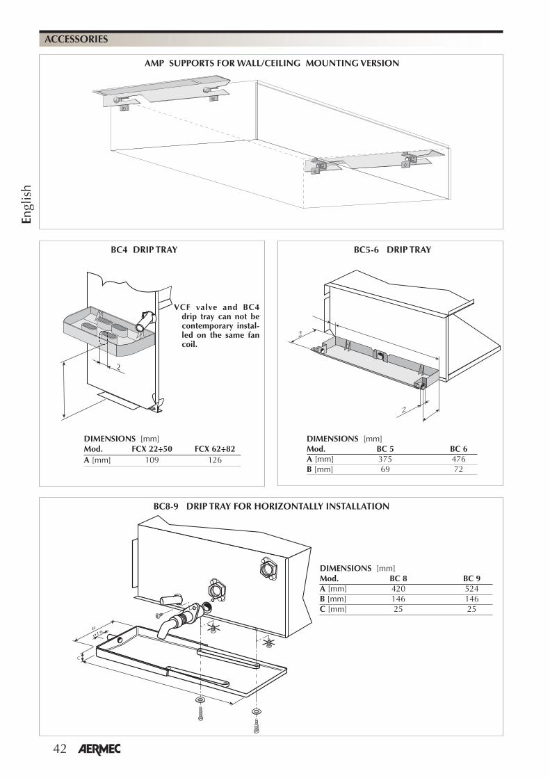
42
Engl
ish
ACCESSORIES
2
2
2
BC4 DRIP TRAY BC5-6 DRIP TRAY
DIMENSIONS [mm]Mod. FCX 22÷50 FCX 62÷82A [mm] 109 126
DIMENSIONS [mm]Mod. BC 5 BC 6A [mm] 375 476B [mm] 69 72
��
�
BC8-9 DRIP TRAY FOR HORIZONTALLY INSTALLATION
DIMENSIONS [mm]Mod. BC 8 BC 9A [mm] 420 524B [mm] 146 146C [mm] 25 25
VCF valve and BC4 drip tray can not be contemporary instal-led on the same fan coil.
AMP SUPPORTS FOR WALL/CEILING MOUNTING VERSION
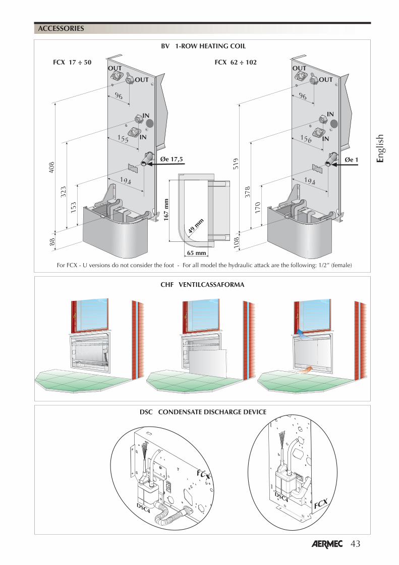
43
Engl
ish
ACCESSORIES
BV 1-ROW HEATING COIL
���
���
��
���
��
���
!"��#�
�$
���
���
�$
��
��
��
���
���
���
�$
!"�
�$
���
���
FCX 17 ÷ 50 FCX 62 ÷ 102
For FCX - U versions do not consider the foot - For all model the hydraulic attack are the following: 1/2” (female)
���%%
��%%
��%%
CHF VENTILCASSAFORMA
���
&��� ���&���
DSC CONDENSATE DISCHARGE DEVICE
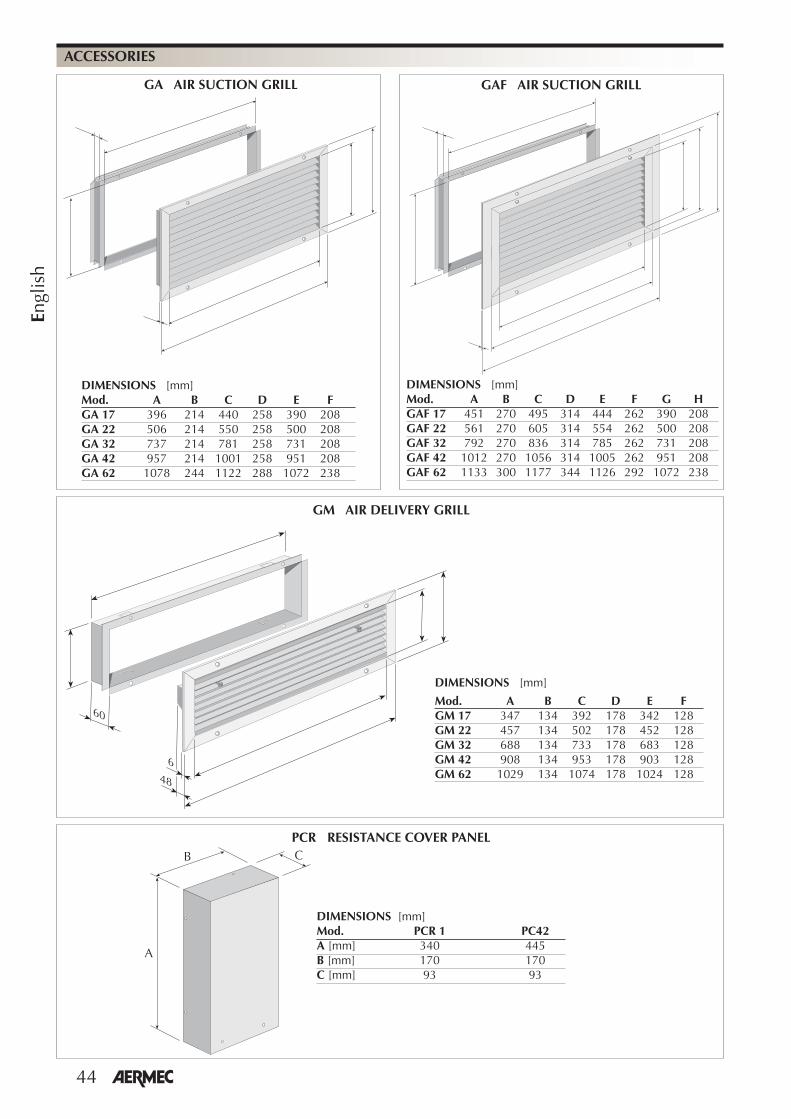
44
Engl
ish
GAF AIR SUCTION GRILL GA AIR SUCTION GRILL
DIMENSIONS [mm]Mod. A B C D E FGA 17 396 214 440 258 390 208GA 22 506 214 550 258 500 208GA 32 737 214 781 258 731 208GA 42 957 214 1001 258 951 208GA 62 1078 244 1122 288 1072 238
DIMENSIONS [mm]Mod. A B C D E F G HGAF 17 451 270 495 314 444 262 390 208GAF 22 561 270 605 314 554 262 500 208GAF 32 792 270 836 314 785 262 731 208GAF 42 1012 270 1056 314 1005 262 951 208GAF 62 1133 300 1177 344 1126 292 1072 238
ACCESSORIES
60
6
48
DIMENSIONS [mm]
Mod. A B C D E FGM 17 347 134 392 178 342 128GM 22 457 134 502 178 452 128GM 32 688 134 733 178 683 128GM 42 908 134 953 178 903 128GM 62 1029 134 1074 178 1024 128
GM AIR DELIVERY GRILL
�
�PCR RESISTANCE COVER PANEL
DIMENSIONS [mm]Mod. PCR 1 PC42A [mm] 340 445B [mm] 170 170C [mm] 93 93
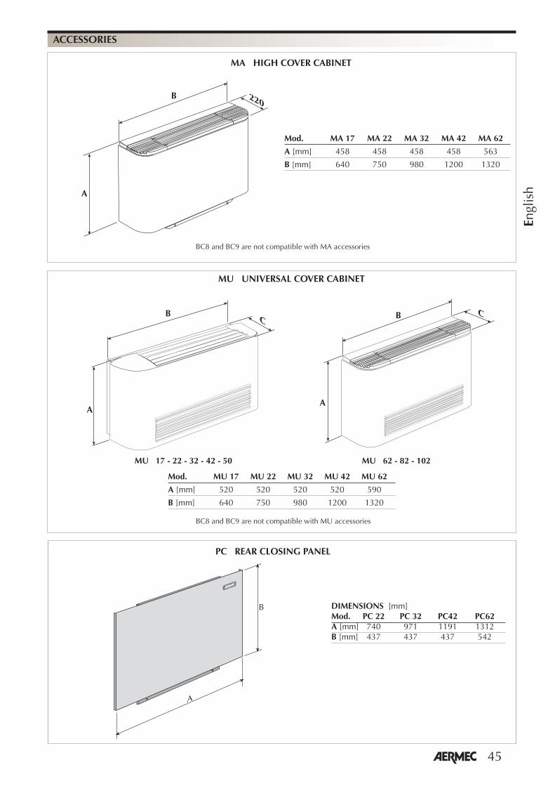
45
Engl
ish
ACCESSORIES
�
��
�
� ���
�
� �
MU 17 - 22 - 32 - 42 - 50 MU 62 - 82 - 102
Mod. MA 17 MA 22 MA 32 MA 42 MA 62
A [mm] 458 458 458 458 563
B [mm] 640 750 980 1200 1320
Mod. MU 17 MU 22 MU 32 MU 42 MU 62
A [mm] 520 520 520 520 590
B [mm] 640 750 980 1200 1320
MA HIGH COVER CABINET
MU UNIVERSAL COVER CABINET
BC8 and BC9 are not compatible with MA accessories
BC8 and BC9 are not compatible with MU accessories
�
PC REAR CLOSING PANEL
DIMENSIONS [mm]Mod. PC 22 PC 32 PC42 PC62A [mm] 740 971 1191 1312B [mm] 437 437 437 542
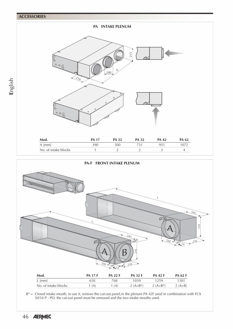
46
Engl
ish
ACCESSORIES
�
���
������ �� ��
��
�
��
���
�
�
����� ����
�
�
�
PA-F FRONT INTAKE PLENUM
Mod. PA 17 F PA 22 F PA 32 F PA 42 F PA 62 FL [mm] 658 768 1039 1259 1381No. of intake blocks 1 (A) 1 (A) 2 (A+B*) 2 (A+B*) 2 (A+B)
B* = Closed intake mouth, to use it, remove the cut-out panel,in the plenum PA 42F used in combination with FCX 50/54 P - PO, the cut-out panel must be removed and the two intake mouths used.
��
�
���
���
PA INTAKE PLENUM
Mod. PA 17 PA 22 PA 32 PA 42 PA 62A [mm] 390 500 731 951 1072No. of intake blocks 1 2 2 3 4
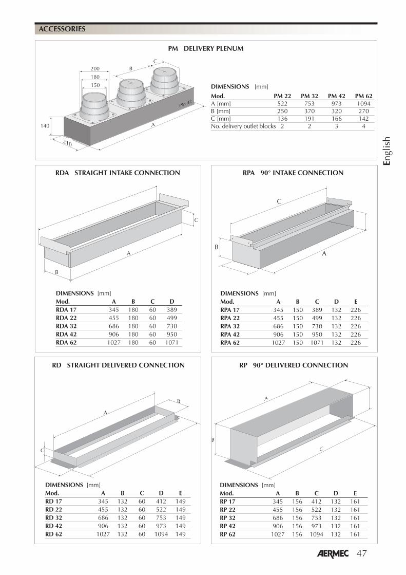
47
Engl
ish
ACCESSORIES
���
���
�
���
���
���
�
�����
PM DELIVERY PLENUM
DIMENSIONS [mm]
Mod. PM 22 PM 32 PM 42 PM 62A [mm] 522 753 973 1094B [mm] 250 370 320 270C [mm] 136 191 166 142No. delivery outlet blocks 2 2 3 4
B
A
C
C
BA
C
A
B
RD STRAIGHT DELIVERED CONNECTION
A
C
B
DIMENSIONS [mm]Mod. A B C D ERD 17 345 132 60 412 149RD 22 455 132 60 522 149RD 32 686 132 60 753 149RD 42 906 132 60 973 149RD 62 1027 132 60 1094 149
DIMENSIONS [mm]Mod. A B C D ERP 17 345 156 412 132 161RP 22 455 156 522 132 161RP 32 686 156 753 132 161RP 42 906 156 973 132 161RP 62 1027 156 1094 132 161
RP 90° DELIVERED CONNECTION
RDA STRAIGHT INTAKE CONNECTION
DIMENSIONS [mm]Mod. A B C DRDA 17 345 180 60 389RDA 22 455 180 60 499RDA 32 686 180 60 730RDA 42 906 180 60 950RDA 62 1027 180 60 1071
DIMENSIONS [mm]Mod. A B C D ERPA 17 345 150 389 132 226RPA 22 455 150 499 132 226RPA 32 686 150 730 132 226RPA 42 906 150 950 132 226RPA 62 1027 150 1071 132 226
RPA 90° INTAKE CONNECTION
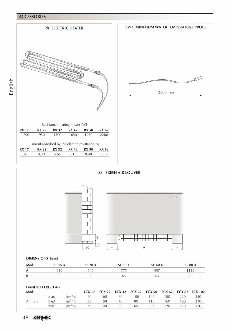
48
Engl
ish
ACCESSORIES
�������
SW3 MINIMUM WATER TEMPERATURE PROBERX ELECTRIC HEATER
Resistance heating power [W]
RX 17 RX 22 RX 32 RX 42 RX 50 RX 62 700 950 1300 1650 1950 2200
Current absorbed by the electric resistance[A]
RX 17 RX 22 RX 32 RX 42 RX 50 RX 623,04 4,13 5,65 7,17 8,48 9,57
���
���
SE FRESH AIR LOUVER
DIMENSIONS [mm]
Mod. SE 15 X SE 20 X SE 30 X SE 40 X SE 80 X
A 436 546 777 997 1118
B 65 65 65 65 85
HANDLED FRESH AIRMod. FCX 17 FCX 22 FCX 32 FCX 42 FCX 50 FCX 62 FCX 82 FCX 102 max [m3/h] 40 60 80 100 140 180 220 250Air flow med [m3/h] 35 50 70 80 115 160 190 210 min. [m3/h] 30 40 50 65 90 120 150 170
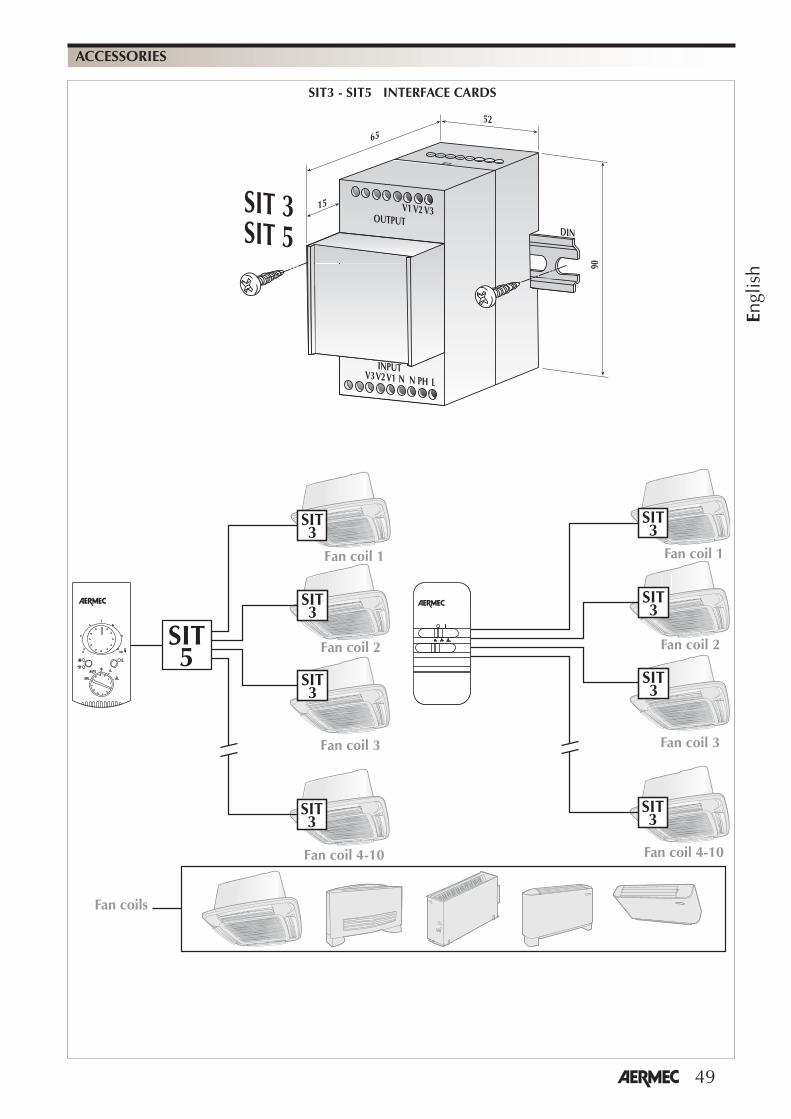
49
Engl
ish
�'()*+,����
�'()*+,�
�'()*+,�
�'()*+,�
����
����
����
����
����
����
����
����
����
�'()*+,����
�'()*+,�
�'()*+,�
�'()*+,�
�'()*+,-
SIT3 - SIT5 INTERFACE CARDS
���� �������
$ . /���� $���$��
��
��
��
��
&�$
��������
ACCESSORIES

50
Engl
ish
VCF valve and BC4 drip tray can not be contemporary installed on the same fan coil.
A
B
AB
INOUT
TECHNICAL SPECIFICATIONS:Power supply: 230V (±10%) ~ 50HzStart-up input power: 46VAOperation input power: 2,5WWater temperature range: 4°C ÷ 80°C Liquids acqua (con glicole ≤ 50%)Operation time: 2 min ÷ 4minMaximum differential pressure: 30kPaMaximum work pressure applied to fan coil: 800kPaEnvironmental working condition
temperature: 0°C ÷ 40°C relative humidity: 10% ÷ 90% without condensation
Storaging environmental conditiontemperature: -18°C ÷ 60°C relative humidity: 10% ÷ 90% without condensation
Actuator water protection degree: IP44 acc.to EN 60529Actuator electrical protection degree: Classe IIFlow direction in the valve (see fig.)
with fed valve A - ABwith not fed valve B - AB
Valve attack [mm] Mod. VCF 41 VCF 42 VCF 43 VCF 44 VCF 45A - AB - B 3/4” 3/4” 3/4” 1/2” 1/2”
Pressure drop Mod. VCF 41 VCF 42 VCF 43 VCF 44 VCF 45Kvs AB-A 2,5 2,5 2,5 1,7 1,7Kvs AB-B (by-pass) 1,6 1,6 1,6 1,2 1,2
Flow direction
∆p [kPa] = Pressure drop q [m3/h] = Water flow rate
ACCESSORIES
VCF 44 (1/2”)
46
3/4”
VCF 41 (3/4”) VCF 42 (3/4”)
1/2”
54
40
38 37
102
31
100
166
FAN COIL
VCF41VCF42forFCX, FCS, FHX
VCF44forBV
VCF43forFCX, FCS, FHX
VCF45forBV
�����������
�
VCF 45 (1/2”)
46
3/4”
1/2”
58
FAN COIL
VCF 43 (3/4”)
40 109
179
155
38 37
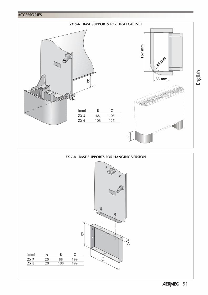
51
Engl
ish
ACCESSORIES
���%%
��%%
��%%
�
[mm] B CZX 5 88 105ZX 6 108 125
ZX 5-6 BASE SUPPORTS FOR HIGH CABINET
�
�
[mm] A B CZX 7 20 88 199ZX 8 20 108 199
ZX 7-8 BASE SUPPORTS FOR HANGING VERSION
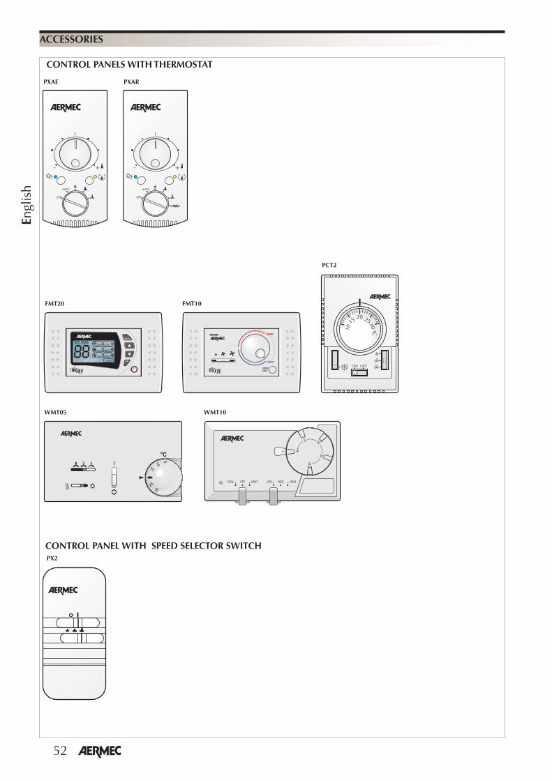
52
Engl
ish
ACCESSORIES
��
!�
���
!�
�0���
������
������
�����
�0���
"# "��
���
�� �� �����
���
0��� 0���
��
CONTROL PANELS WITH THERMOSTAT
CONTROL PANEL WITH SPEED SELECTOR SWITCH
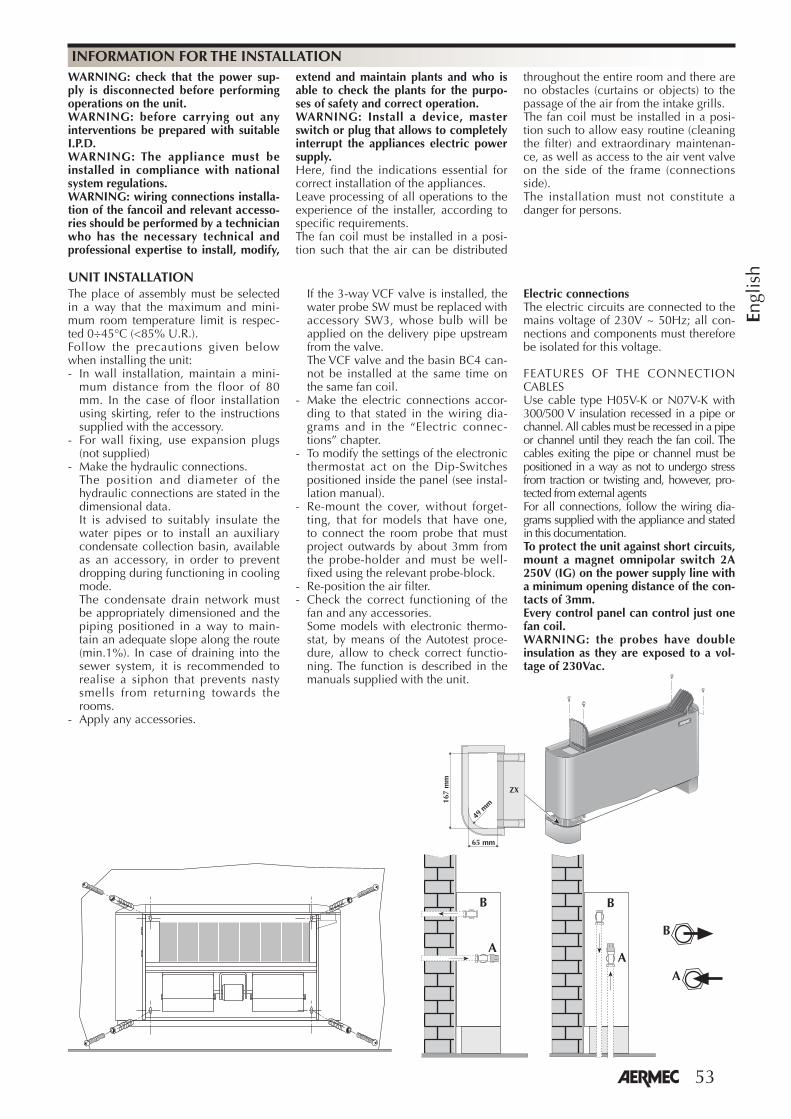
53
Engl
ish
The place of assembly must be selected in a way that the maximum and mini-mum room temperature limit is respec-ted 0÷45°C (<85% U.R.).Follow the precautions given below when installing the unit:- In wall installation, maintain a mini-
mum distance from the floor of 80 mm. In the case of floor installation using skirting, refer to the instructions supplied with the accessory.
- For wall fixing, use expansion plugs (not supplied)
- Make the hydraulic connections. The position and diameter of the
hydraulic connections are stated in the dimensional data.
It is advised to suitably insulate the water pipes or to install an auxiliary condensate collection basin, available as an accessory, in order to prevent dropping during functioning in cooling mode.
The condensate drain network must be appropriately dimensioned and the piping positioned in a way to main-tain an adequate slope along the route (min.1%). In case of draining into the sewer system, it is recommended to realise a siphon that prevents nasty smells from returning towards the rooms.
- Apply any accessories.
If the 3-way VCF valve is installed, the water probe SW must be replaced with accessory SW3, whose bulb will be applied on the delivery pipe upstream from the valve.
The VCF valve and the basin BC4 can-not be installed at the same time on the same fan coil.
- Make the electric connections accor-ding to that stated in the wiring dia-grams and in the “Electric connec-tions” chapter.
- To modify the settings of the electronic thermostat act on the Dip-Switches positioned inside the panel (see instal-lation manual).
- Re-mount the cover, without forget-ting, that for models that have one, to connect the room probe that must project outwards by about 3mm from the probe-holder and must be well-fixed using the relevant probe-block.
- Re-position the air filter.- Check the correct functioning of the
fan and any accessories. Some models with electronic thermo-
stat, by means of the Autotest proce-dure, allow to check correct functio-ning. The function is described in the manuals supplied with the unit.
Electric connectionsThe electric circuits are connected to the mains voltage of 230V ~ 50Hz; all con-nections and components must therefore be isolated for this voltage.
FEATURES OF THE CONNECTION CABLESUse cable type H05V-K or N07V-K with 300/500 V insulation recessed in a pipe or channel. All cables must be recessed in a pipe or channel until they reach the fan coil. The cables exiting the pipe or channel must be positioned in a way as not to undergo stress from traction or twisting and, however, pro-tected from external agentsFor all connections, follow the wiring dia-grams supplied with the appliance and stated in this documentation.To protect the unit against short circuits, mount a magnet omnipolar switch 2A 250V (IG) on the power supply line with a minimum opening distance of the con-tacts of 3mm.Every control panel can control just one fan coil.WARNING: the probes have double insulation as they are exposed to a vol-tage of 230Vac.
INFORMATION FOR THE INSTALLATION
��
��
�
�
���%%
��%%
��%%
��
WARNING: check that the power sup-ply is disconnected before performing operations on the unit.WARNING: before carrying out any interventions be prepared with suitable I.P.D.WARNING: The appliance must be installed in compliance with national system regulations.WARNING: wiring connections installa-tion of the fancoil and relevant accesso-ries should be performed by a technician who has the necessary technical and professional expertise to install, modify,
extend and maintain plants and who is able to check the plants for the purpo-ses of safety and correct operation. WARNING: Install a device, master switch or plug that allows to completely interrupt the appliances electric power supply.Here, find the indications essential for correct installation of the appliances.Leave processing of all operations to the experience of the installer, according to specific requirements.The fan coil must be installed in a posi-tion such that the air can be distributed
throughout the entire room and there are no obstacles (curtains or objects) to the passage of the air from the intake grills.The fan coil must be installed in a posi-tion such to allow easy routine (cleaning the filter) and extraordinary maintenan-ce, as well as access to the air vent valve on the side of the frame (connections side).The installation must not constitute a danger for persons.
UNIT INSTALLATION
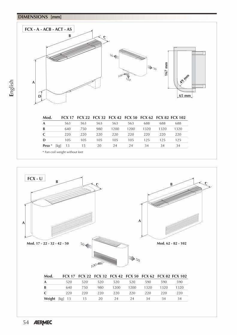
54
Engl
ish
�
��
�
�
&
�
���
��
���
��
FCX - A - ACB - ACT - AS
FCX - U
Mod. 17 - 22 - 32 - 42 - 50 Mod. 62 - 82 - 102
Mod. FCX 17 FCX 22 FCX 32 FCX 42 FCX 50 FCX 62 FCX 82 FCX 102A 563 563 563 563 563 688 688 688
B 640 750 980 1200 1200 1320 1320 1320
C 220 220 220 220 220 220 220 220
D 105 105 105 105 105 125 125 125
Peso * [kg] 13 15 20 24 24 34 34 34
Mod. FCX 17 FCX 22 FCX 32 FCX 42 FCX 50 FCX 62 FCX 82 FCX 102 A 520 520 520 520 520 590 590 590
B 640 750 980 1200 1200 1320 1320 1320
C 220 220 220 220 220 220 220 220
Weight [kg] 13 15 20 24 24 34 34 34
* Fan coil weight without feet
���%%
��%%
��%%
���
��
��
DIMENSIONS [mm]
�
� �
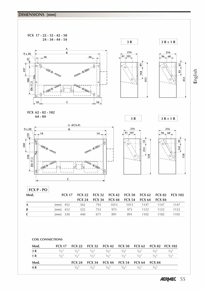
55
Engl
ish
�
�
���
���
�� ��
����� ���
�����
���
�1����2�3��
���
�����
����� ��
���
!"��#�
� ����
��
�3��
���
����� ���
�����
����
�� ��
����� ��
���
���
���
��!"��#�
FCX 17 - 22 - 32 - 42 - 50 24 - 34 - 44 - 54
FCX 62 - 82 - 102 64 - 84
3 R 3 R + 1 R
3 R 3 R + 1 R
COIL CONNECTIONS
Mod. FCX 17 FCX 22 FCX 32 FCX 42 FCX 50 FCX 62 FCX 82 FCX 1023 R 1/2” 1/2” 1/2” 3/4” 3/4” 3/4” 3/4” 3/4”
1 R 1/2” 1/2” 1/2” 1/2” 1/2” 1/2” 1/2” 1/2”
Mod. FCX 24 FCX 34 FCX 44 FCX 54 FCX 64 FCX 844 R 3/4” 3/4” 3/4” 3/4” 3/4” 3/4”
Mod. FCX 17 FCX 22 FCX 32 FCX 42 FCX 50 FCX 62 FCX 82 FCX 102 FCX 24 FCX 34 FCX 44 FCX 54 FCX 64 FCX 84 A [mm] 452 562 793 1013 1013 1147 1147 1147
B [mm] 412 522 753 973 973 1122 1122 1122
C [mm] 330 440 671 891 891 1102 1102 1102
FCX P - PO
DIMENSIONS [mm]
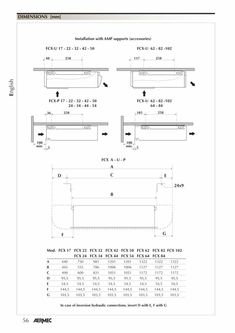
56
Engl
ish
�� ��� ��� ���
�� ��� ��� ���
&
�
�
�
���%+(4
���%+(4� �
��3�
5�
FCX-P 17 - 22 - 32 - 42 - 5024 - 34 - 44 - 54
FCX-U 17 - 22 - 32 - 42 - 50 FCX-U 62 - 82 -102
FCX-U 62 - 82 -102 64 - 84
Mod. FCX 17 FCX 22 FCX 32 FCX 42 FCX 50 FCX 62 FCX 82 FCX 102 FCX 24 FCX 34 FCX 44 FCX 54 FCX 64 FCX 84A 640 750 981 1201 1201 1322 1322 1322
B 445 555 786 1006 1006 1127 1127 1127
C 490 600 831 1051 1051 1172 1172 1172
D 95,5 95,5 95,5 95,5 95,5 95,5 95,5 95,5
E 54,5 54,5 54,5 54,5 54,5 54,5 54,5 54,5
F 144,5 144,5 144,5 144,5 144,5 144,5 144,5 144,5
G 103,5 103,5 103,5 103,5 103,5 103,5 103,5 103,5
In case of inversion hydraulic connections, invert D with E, F with G
FCX A - U - P
Installation with AMP supports (accessories)
DIMENSIONS [mm]
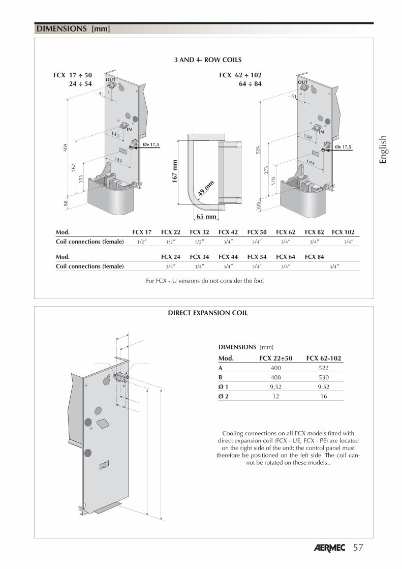
57
Engl
ish
3 AND 4- ROW COILS
��
���
���
��
���
��
��
!"��#�
�$
���
��
��
���
��
���
���
���
!"��#�
�$
���FCX 17 ÷ 50
24 ÷ 54FCX 62 ÷ 102
64 ÷ 84
For FCX - U versions do not consider the foot
DIRECT EXPANSION COIL
DIMENSIONS [mm]
Mod. FCX 22÷50 FCX 62-102A 400 522
B 408 530
Ø 1 9,52 9,52
Ø 2 12 16
Cooling connections on all FCX models fitted withdirect expansion coil (FCX - UE, FCX - PE) are located
on the right side of the unit; the control panel musttherefore be positioned on the left side. The coil can-
not be rotated on these models..
Mod. FCX 17 FCX 22 FCX 32 FCX 42 FCX 50 FCX 62 FCX 82 FCX 102
Coil connections (female) 1/2” 1/2” 1/2” 3/4” 3/4” 3/4” 3/4” 3/4”
Mod. FCX 24 FCX 34 FCX 44 FCX 54 FCX 64 FCX 84
Coil connections (female) 3/4” 3/4” 3/4” 3/4” 3/4” 3/4”
���%%
��%%
��%%
DIMENSIONS [mm]

58
Engl
ish
�� � � � � �
CO
MU
NE
- B
L
MIN
. VEL
. - R
O
MED
. VEL
. - M
A
MA
X. V
EL. -
NE
NE
GRBI
VE
GI
BL AR
RO
MABL
AL = Alimentatore 12V Power supply 12V Alimentation electrique 12V Spannung 12V Alimentador
CE = Contatto esterno EX External contact Contact extérieur Externer Kontakt Contacto externo
CN = Connettore Connector Connecteur Schütz Conector
CRE = Contattore resistenza elettrica Electric heater contactor Contacteur résistance eléctrique El. Heizregister-Schutz Contactor de la resistencia eléctrica
F = Fusibile • Fuse • Fusible Sicherung • Fusible
IG = Interruttore generale • Main switch Interupteur général • Hauptschalter Interruptor general
M = Morsettiera • Terminal board Boitier • Klemmleiste Placa de bornes
ML = Motore aletta Louvre motor Moteur defl ecteur Motor- Umlenkklappe Lamas motorizadas
MS = Microinterruttore griglia (Solo per i modelli che ne sono provvisti) Louvre microswitch (Only for the appropriate models) Micro-interrupteur grille (Uniquement pour les modèles qui en sont fournis) Mikroschalter Gitter (Nur bei Modellen, die damit ausgestattet sind) Microinterruptor de la rejilla de impulsión (Sólo para los modelos que lo incluyen)
MV = Motore ventilatore • Fan motor Moteur ventilateur • Ventilatormotor Motor del ventilador PE = Collegamento a terra GND Earth connection Mise à terre Erdanschluss Toma de tierra
RE = Resistenza elettrica • Electric heater RX = Résistance électrique • Elt. Heizregister Resistencia eléctrica
SA = Sonda ambiente • Room sensor Sonde ambiante • Raumtemperaturfuhler Sonda ambiente
SC = Scheda di controllo Electronic control board Platine de contrôle • Steuerschaltkreis Tarjeta electrónica de control
SW = Sonda minima temperatura acqua Water low temperature sensor Sonde minimum temp. eau Wasserfühler Sonda temperatura mínima del agua
TR = Trasformatore • Transformer Transformateur Transformator • Transformador
TSR = Termostato a riarmo automatico Automatic resetting thermostat Thermostat à réarmement automatique Thermostat automatischer Entriegelung Termostato de rearme automático
TSRM= Termostato a riarmo manuale Manual resetting thermostat Thermostat à réarmement manuel Thermostat manueller Entriegelung Termostato de rearme manual
VCF =Valvola solenoide • Solenoid valve Vanne solenoide • Magnetventil Válvula solenoide
VC = Valvola solenoide caldo Solenoid valve hot Vanne magnétique chaud Magnetventil Heizbetrieb Válvula solenoide para calor
VF = Valvola solenoide freddo Solenoid valve cold Vanne magnétique froid Magnetventil Kühlbetrieb Válvula solenoide para frío
= Componenti non forniti Components not supplied Composants non fournis
Nicht lieferbare Teile Componentes no suministrados
= Componenti forniti optional Optional components Composants en option Optionsteile
Componentes opcionales
= Collegamenti da eseguire in loco On-site wiring Raccordements à effectuer in situ
Vor Ort auszuführende Anschlüsse Cableado in situ
AR = Arancio • Orange • Orange • Orange • NaranjaBI = Bianco • White • Blanc • Weiss • Blanco BL = Blu • Blue • Bleu • Blau • Azul GR = Grigio • Grey • Gris • Gray • GrisMA = Marrone • Brown • Marron • Braun • MarrónNE = Nero • Black • Noir • Schwarz • NegroRO = Rosso • Red • Rouge • Rot • RojoVE = Verde • Green • Vert • Grün • VerdeVI = Viola • Violet • Violet • Violet • Violeta
LEGENDA • READING KEY • LEGENDE • LEGENDE • LEYENDA
SCHEMA DI COLLEGAMENTO MOTORE FCX - PO • FCX - PO MOTOR CONNECTION DIAGRAMSCHEMA DE RACCORDEMENT MOTEUR FCX - PO • ANSCHLUSSPLAN MOTOR FCX - PO
ESQUEMA DE CONEXIONADO ELÉCTRICO DEL MOTOR FCX - PO
Le velocità disponibili sono numerate da 1 a 7 in ordine decrescente di velocitàAvailable speeds are numbered from 1 to 7 following a speed decreasing orderLes vitesses disponibles sont numeratées de 1 à 7 en ordre de vitesse décroissanteDie verfügbaren Drehzahlen sind von 1 zu 7 mit abnehmender Drehzahlstufe numeriertLas velocidades disponibles se numeran, en orden decreciente, de 1 a 7.
SCHEMI ELETTRICI • WIRING DIAGRAMS • SCHEMAS ELECTRIQUES • SCHALTPLÄNE • ESQUEMAS ELÉCTRICOS
Gli schemi elettrici sono soggetti ad un continuo aggiornamento, è obbligatorio quindi fare riferimento a quelli a bordo macchina.A l l w i r i n g d i a g r a m s a r e c o n s t a n t l y u p d a t e d . P l e a s e r e f e r t o t h e o n e s s u p p l i e d w i t h t h e u n i t .Nos schémas électr iques étant constamment mis à jour, i l faut absolument se référer à ceux fournis à bord de nos apparei ls .Die Schaltpläne werden ständig aktualisiert, deswegen muss man sich stets auf das mit dem Gerät gelieferte Schaltschema beziehen.El cableado de las máquinas es sometido a actualizaciones constantes. Por favor, para cada unidad hagan referencia a los esquemas suministrados con la misma.
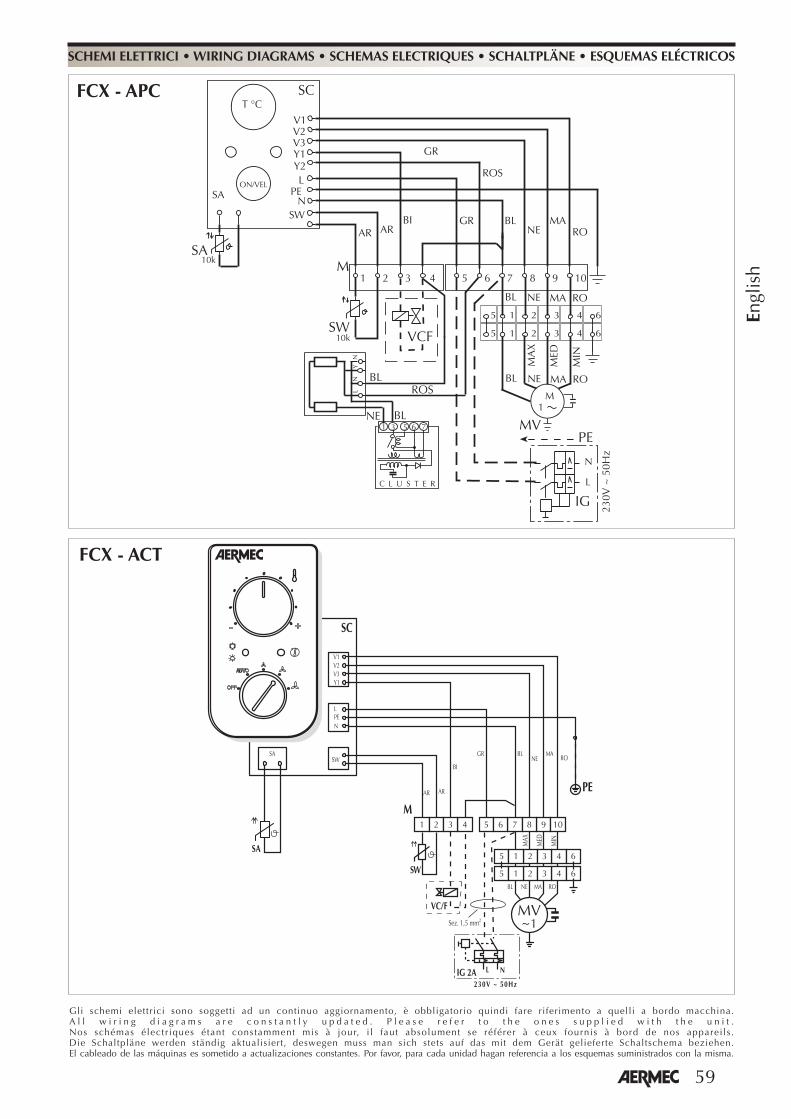
59
Engl
ish
SCHEMI ELETTRICI • WIRING DIAGRAMS • SCHEMAS ELECTRIQUES • SCHALTPLÄNE • ESQUEMAS ELÉCTRICOS
Gli schemi elettrici sono soggetti ad un continuo aggiornamento, è obbligatorio quindi fare riferimento a quelli a bordo macchina.A l l w i r i n g d i a g r a m s a r e c o n s t a n t l y u p d a t e d . P l e a s e r e f e r t o t h e o n e s s u p p l i e d w i t h t h e u n i t .Nos schémas électr iques étant constamment mis à jour, i l faut absolument se référer à ceux fournis à bord de nos apparei ls .Die Schaltpläne werden ständig aktualisiert, deswegen muss man sich stets auf das mit dem Gerät gelieferte Schaltschema beziehen.El cableado de las máquinas es sometido a actualizaciones constantes. Por favor, para cada unidad hagan referencia a los esquemas suministrados con la misma.
$�
$�
��%
&���
"#'()�
(�(�(�*�
��)
#$+
���(
�,��
�-.
�/
��
��%
�/
�
0
�
1/
�
1/
�
�
#
�
�
#)
�
��
/"
��
�)
$�
$+(��
01
*�/"$
��
��
�
�)�
�0#
�(
� #) �� /"
� #) �� /"
�
�
� �
�
�
�
�
�
�
�#
*#
� � 2 $ & ) /
� � � �#)
�
�
/"$
� � ��
� #) �� /"
�(,�
���
�)�
�0#
0
$3.4��������
����
� � �
�#)
��/"
1/
(�(�(�*�
��)#
$+
� �
��
$�
0
�/�/
��
� � � � ��
� � � ��
�5�� / $
����6��.7
FCX - ACT
FCX - APC
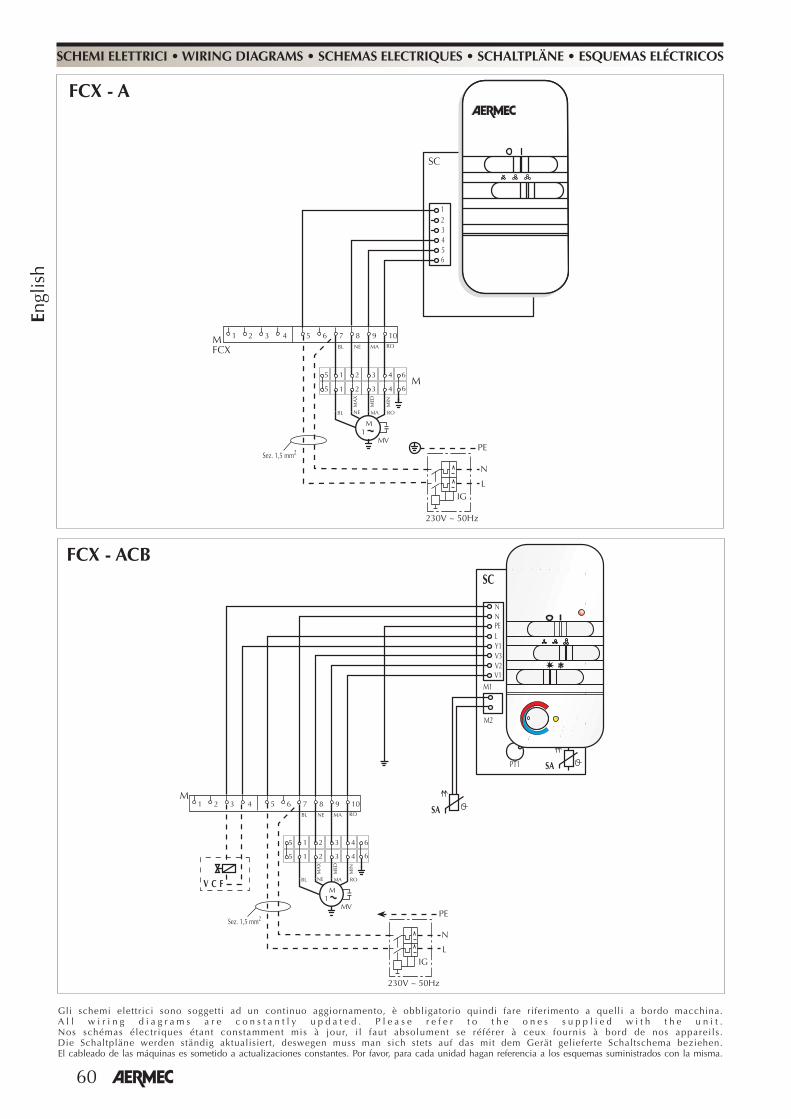
60
Engl
ish
��
��
##�)�*�(�(�(�
��
5��
)�& 0#&���
�&�
��
�� � � � � � � ��
���(�,���-.
�
#
�)
01
�
�
� �
�
�
�
�
�
�
�(
��
��
�
�)�
�0#
� #) �� /"
� #) �� /"
� � �
$3.4��������
��
FCX - ACB
�����
$�
� � � � � � � ��
���(�,���-.
�
#
�)
01
�
�
� �
�
�
�
�
�
�
$3.4��������
����
�
�(
��
��
�
�)�
�0#
� #) �� /"
� #) �� /"
FCX - A
SCHEMI ELETTRICI • WIRING DIAGRAMS • SCHEMAS ELECTRIQUES • SCHALTPLÄNE • ESQUEMAS ELÉCTRICOS
Gli schemi elettrici sono soggetti ad un continuo aggiornamento, è obbligatorio quindi fare riferimento a quelli a bordo macchina.A l l w i r i n g d i a g r a m s a r e c o n s t a n t l y u p d a t e d . P l e a s e r e f e r t o t h e o n e s s u p p l i e d w i t h t h e u n i t .Nos schémas électr iques étant constamment mis à jour, i l faut absolument se référer à ceux fournis à bord de nos apparei ls .Die Schaltpläne werden ständig aktualisiert, deswegen muss man sich stets auf das mit dem Gerät gelieferte Schaltschema beziehen.El cableado de las máquinas es sometido a actualizaciones constantes. Por favor, para cada unidad hagan referencia a los esquemas suministrados con la misma.
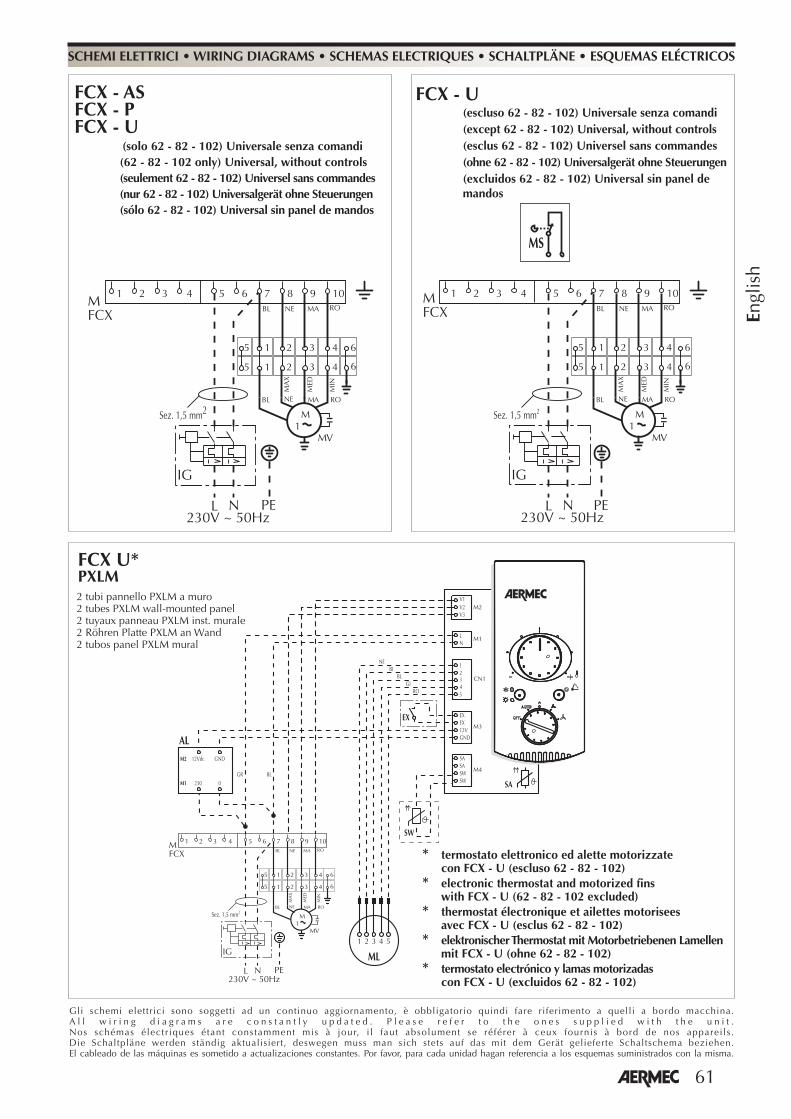
61
Engl
ish
� � � � � � � ��
�
�
� �
�
�
�
�
�
�
�(
��
��
�
�)�
�0#
� #) �� /"
� #) �� /"
$3.4��������
���(�,���-.� #
01
0�
�)
����
����
� � � � � � � ��
�
�
� �
�
�
�
�
�
�
�(
��
��
�
�)�
�0#
� #) �� /"
� #) �� /"
$3.4��������
���(�,���-.� #
01
�)
FCX - U (escluso 62 - 82 - 102) Universale senza comandi (except 62 - 82 - 102) Universal, without controls (esclus 62 - 82 - 102) Universel sans commandes (ohne 62 - 82 - 102) Universalgerät ohne Steuerungen (excluidos 62 - 82 - 102) Universal sin panel de mandos
FCX - AS FCX - P FCX - U (solo 62 - 82 - 102) Universale senza comandi (62 - 82 - 102 only) Universal, without controls (seulement 62 - 82 - 102) Universel sans commandes (nur 62 - 82 - 102) Universalgerät ohne Steuerungen (sólo 62 - 82 - 102) Universal sin panel de mandos
�1/
�
��
0/� � � � �
#)
/"
0 �
10
�
�/
� � � � � � � ��
�
�
� �
�
�
�
�
�
�
�(
��
��
�
�)�
�0#
� #) �� /"
� #) �� /"
$3.4��������
���(�,���-.� #
01
�)
����
��
#�
(�(�
(�
�����
)�)���(1#�
$�$�$+$+
��
�#�
��
��
��(67 1#�
��� �
0�
0�
* termostato elettronico ed alette motorizzate con FCX - U (escluso 62 - 82 - 102)* electronic thermostat and motorized fins with FCX - U (62 - 82 - 102 excluded)* thermostat électronique et ailettes motorisees avec FCX - U (esclus 62 - 82 - 102)* elektronischer Thermostat mit Motorbetriebenen Lamellen mit FCX - U (ohne 62 - 82 - 102)* termostato electrónico y lamas motorizadas con FCX - U (excluidos 62 - 82 - 102)
SCHEMI ELETTRICI • WIRING DIAGRAMS • SCHEMAS ELECTRIQUES • SCHALTPLÄNE • ESQUEMAS ELÉCTRICOS
Gli schemi elettrici sono soggetti ad un continuo aggiornamento, è obbligatorio quindi fare riferimento a quelli a bordo macchina.A l l w i r i n g d i a g r a m s a r e c o n s t a n t l y u p d a t e d . P l e a s e r e f e r t o t h e o n e s s u p p l i e d w i t h t h e u n i t .Nos schémas électr iques étant constamment mis à jour, i l faut absolument se référer à ceux fournis à bord de nos apparei ls .Die Schaltpläne werden ständig aktualisiert, deswegen muss man sich stets auf das mit dem Gerät gelieferte Schaltschema beziehen.El cableado de las máquinas es sometido a actualizaciones constantes. Por favor, para cada unidad hagan referencia a los esquemas suministrados con la misma.
FCX U*PXLM2 tubi pannello PXLM a muro2 tubes PXLM wall-mounted panel2 tuyaux panneau PXLM inst. murale2 Röhren Platte PXLM an Wand2 tubos panel PXLM mural

62
Engl
ish
�����
���
� � � � � � � ��
���(�,���-.
�
#
�)
01
�
�
� �
�
�
�
�
�
�
�(
��
��
�
�)�
�0#
� #) �� /"
� #) �� /"
$3.4��������
0�8
����
0�8
�
SCHEMI ELETTRICI • WIRING DIAGRAMS • SCHEMAS ELECTRIQUES • SCHALTPLÄNE • ESQUEMAS ELÉCTRICOS
Gli schemi elettrici sono soggetti ad un continuo aggiornamento, è obbligatorio quindi fare riferimento a quelli a bordo macchina.A l l w i r i n g d i a g r a m s a r e c o n s t a n t l y u p d a t e d . P l e a s e r e f e r t o t h e o n e s s u p p l i e d w i t h t h e u n i t .Nos schémas électr iques étant constamment mis à jour, i l faut absolument se référer à ceux fournis à bord de nos apparei ls .Die Schaltpläne werden ständig aktualisiert, deswegen muss man sich stets auf das mit dem Gerät gelieferte Schaltschema beziehen.El cableado de las máquinas es sometido a actualizaciones constantes. Por favor, para cada unidad hagan referencia a los esquemas suministrados con la misma.
� #) �� /"1/
(�(�(�*�
��)#
$+
�&0
��
$�
0�/ �/
� � � � � � � ��
�
�
� �
�
�
�
�
�
�
�(
��
��
�
�)�
�0#
� #) �� /"
� #) �� /"
$3.4��������
���(�,���-.� #
01����
0�8
�
���
�)
����
0�8
FCX PTI + VCF2 tubi pannello PTI a bordo macchina2 tubes PTI panel on board machine2 tuyaux panneau PTI sur l'appareil2 Röhren Platte PTI am Gerät2 tubos panel PTI en el equipo
��
��
##�)�*�(�(�(�
��
5��
)�& 0#&���
�� 0
� � � � � � � ��
���(�,���-.
�
#
�)
01
�
�
� �
�
�
�
�
�
�
�(
��
��
�
�)�
�0#
� #) �� /"
� #) �� /"
� � �
$3.4��������
0�8
����
0�8
�
FCX PXBI + VCF2 tubi pannello PXBI a bordo macchina2 tubes PXBI panel on board machine2 tuyaux panneau PXBI sur l'appareil2 Röhren Platte PXBI am Gerät2 tubos panel PXBI en el equipo
FCX PX2commutatore a distanzaremote switchcommutateur à distanceFernumschalterconmutador remoto
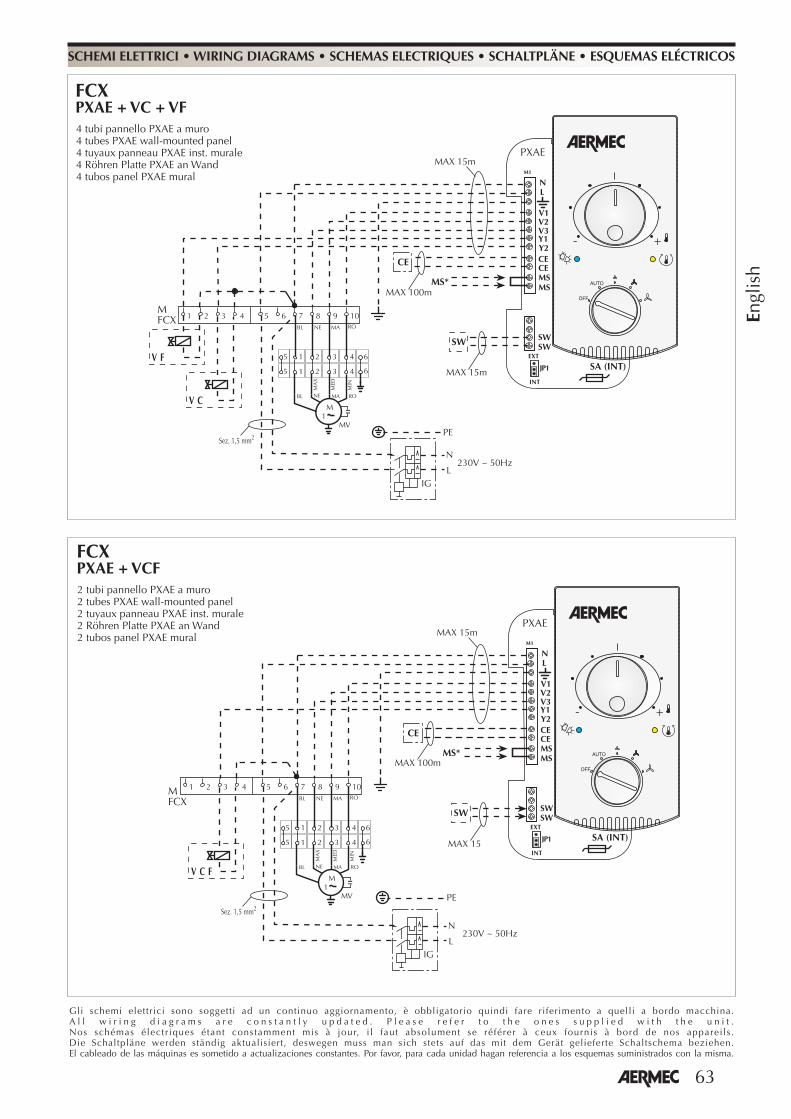
63
Engl
ish
SCHEMI ELETTRICI • WIRING DIAGRAMS • SCHEMAS ELECTRIQUES • SCHALTPLÄNE • ESQUEMAS ELÉCTRICOS
���)
� � � � � � � ��
���(�,���-.�
#
01
!�
��1�$�2
�
$/
��
9�����
9�� � 0�0�
� �
0�
:�
��
�$�
�
�
� �
�
�
�
�
�
�
�(
��
��
�
�)�
�0#
� #) �� /"
� #) �� /"
� �
� �
�
0�8
�������
$3.4��������
��������
�������
�)
����
FCX PXAE + VC + VF
���)
� � � � � � � ��
���(�,���-.�
#
01
!�
��1�$�2
�
$/
��
9�����
9�� � 0�0�
� �
0�
:�
��
�$�
�
�
� �
�
�
�
�
�
�
�(
��
��
�
�)�
�0#
� #) �� /"
� #) �� /"
� � �
�
�������
$3.4��������
0�8
������
�)
��������
����
FCX PXAE + VCF
4 tubi pannello PXAE a muro4 tubes PXAE wall-mounted panel4 tuyaux panneau PXAE inst. murale4 Röhren Platte PXAE an Wand4 tubos panel PXAE mural
2 tubi pannello PXAE a muro2 tubes PXAE wall-mounted panel2 tuyaux panneau PXAE inst. murale2 Röhren Platte PXAE an Wand2 tubos panel PXAE mural
Gli schemi elettrici sono soggetti ad un continuo aggiornamento, è obbligatorio quindi fare riferimento a quelli a bordo macchina.A l l w i r i n g d i a g r a m s a r e c o n s t a n t l y u p d a t e d . P l e a s e r e f e r t o t h e o n e s s u p p l i e d w i t h t h e u n i t .Nos schémas électr iques étant constamment mis à jour, i l faut absolument se référer à ceux fournis à bord de nos apparei ls .Die Schaltpläne werden ständig aktualisiert, deswegen muss man sich stets auf das mit dem Gerät gelieferte Schaltschema beziehen.El cableado de las máquinas es sometido a actualizaciones constantes. Por favor, para cada unidad hagan referencia a los esquemas suministrados con la misma.
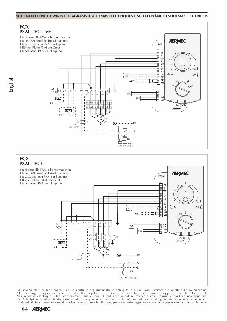
64
Engl
ish
���0
� � � � � � � ��
���(�,���-.
�
#
01
!�
��1�$�2
�
$/
��
9�����
9�� � 0�0�
� �
0�
�
�
� �
�
�
�
�
�
�
�(
��
��
�
�)�
�0#
� #) �� /"
� #) �� /"
� �
� �
0�8
$3.4���������)
�
��
����
SCHEMI ELETTRICI • WIRING DIAGRAMS • SCHEMAS ELECTRIQUES • SCHALTPLÄNE • ESQUEMAS ELÉCTRICOS
FCX PXAI + VC + VF
���0
�
� � � � � � � ��
���(�,���-.
�
#
01
!�
��1�$�2
�
$/
��
9�����
9�� � 0�0�
� �
0�
�
�
� �
�
�
�
�
�
�
�(
��
��
�
�)�
�0#
� #) �� /"
� #) �� /"
� � �
$3.4��������
0�8
�)
�
�� ����
����
FCX PXAI + VCF
4 tubi pannello PXAI a bordo macchina4 tube PXAI panel on board machine4 tuyaux panneau PXAI sur l'appareil4 Röhren Platte PXAI am Gerät4 tubos panel PXAI en el equipo
4 tubi pannello PXAI a bordo macchina4 tube PXAI panel on board machine4 tuyaux panneau PXAI sur l'appareil4 Röhren Platte PXAI am Gerät4 tubos panel PXAI en el equipo
Gli schemi elettrici sono soggetti ad un continuo aggiornamento, è obbligatorio quindi fare riferimento a quelli a bordo macchina.A l l w i r i n g d i a g r a m s a r e c o n s t a n t l y u p d a t e d . P l e a s e r e f e r t o t h e o n e s s u p p l i e d w i t h t h e u n i t .Nos schémas électr iques étant constamment mis à jour, i l faut absolument se référer à ceux fournis à bord de nos apparei ls .Die Schaltpläne werden ständig aktualisiert, deswegen muss man sich stets auf das mit dem Gerät gelieferte Schaltschema beziehen.El cableado de las máquinas es sometido a actualizaciones constantes. Por favor, para cada unidad hagan referencia a los esquemas suministrados con la misma.
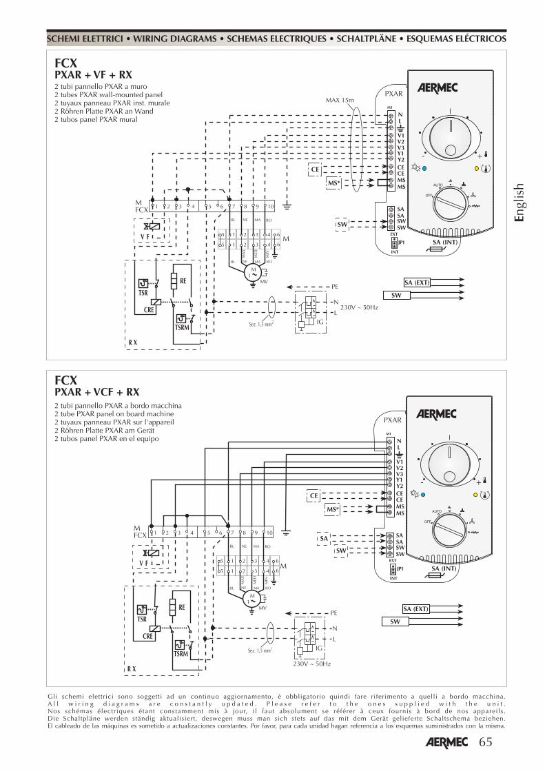
65
Engl
ish
���/
�
� � � � � � � ��
���(�,���-.�
#
�)
01
��1�$�2
�
$/
��
9�����
9�� � 0�0�
� �
0�
:�
��
�$�
�
�
� �
�
�
�
�
�
�
�(
��
��
�
�)�
�0#
� #) �� /"
� #) �� /"�
�������
$3.4��������
0�8
!�
����
��1 ��2
�
� �
� �
����
���
��
���0
�
SCHEMI ELETTRICI • WIRING DIAGRAMS • SCHEMAS ELECTRIQUES • SCHALTPLÄNE • ESQUEMAS ELÉCTRICOS
FCX PXAR + VF + RX
���/
�
� � � � � � � ��
���(�,���-.
�
#
�)
01
��1�$�2
�
$/
��
9�����
9�� � 0�0�
� �
0�
:�
��
�$�
�
�
� �
�
�
�
�
�
�
�(
��
��
�
�)�
�0#
� #) �� /"
� #) �� /"�
$3.4��������
0�8
!�
������
��1 ��2
�
� �
� �
����
���
��
���0
�
FCX PXAR + VCF + RX
2 tubi pannello PXAR a muro2 tubes PXAR wall-mounted panel2 tuyaux panneau PXAR inst. murale2 Röhren Platte PXAR an Wand2 tubos panel PXAR mural
2 tubi pannello PXAR a bordo macchina2 tube PXAR panel on board machine2 tuyaux panneau PXAR sur l'appareil2 Röhren Platte PXAR am Gerät2 tubos panel PXAR en el equipo
Gli schemi elettrici sono soggetti ad un continuo aggiornamento, è obbligatorio quindi fare riferimento a quelli a bordo macchina.A l l w i r i n g d i a g r a m s a r e c o n s t a n t l y u p d a t e d . P l e a s e r e f e r t o t h e o n e s s u p p l i e d w i t h t h e u n i t .Nos schémas électr iques étant constamment mis à jour, i l faut absolument se référer à ceux fournis à bord de nos apparei ls .Die Schaltpläne werden ständig aktualisiert, deswegen muss man sich stets auf das mit dem Gerät gelieferte Schaltschema beziehen.El cableado de las máquinas es sometido a actualizaciones constantes. Por favor, para cada unidad hagan referencia a los esquemas suministrados con la misma.
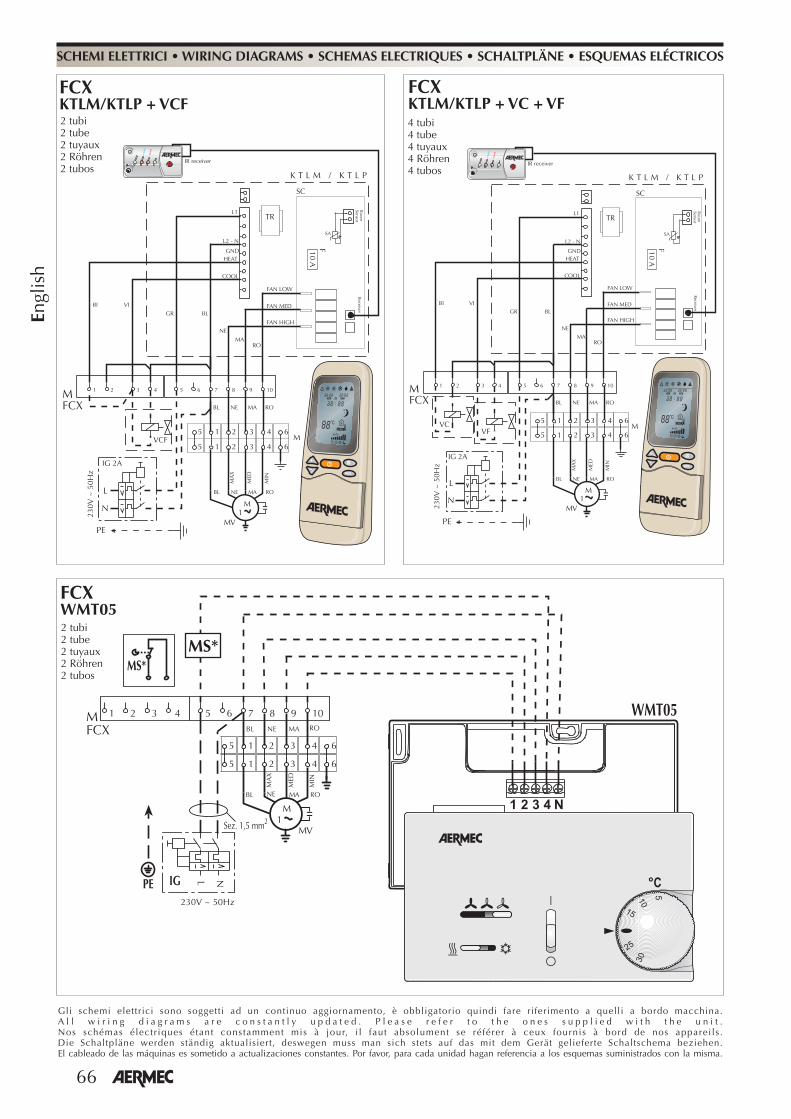
66
Engl
ish
SCHEMI ELETTRICI • WIRING DIAGRAMS • SCHEMAS ELECTRIQUES • SCHALTPLÄNE • ESQUEMAS ELÉCTRICOS
� � � � �
0���
0�8
����
� � � � � � � ��
�
�
� �
�
�
�
�
�
�
���(�,���-.
� #�5
$3.4��������
�(
� #) �� /"
� #) �� /"
��
��
�
�)�
�0#
0�8
Gli schemi elettrici sono soggetti ad un continuo aggiornamento, è obbligatorio quindi fare riferimento a quelli a bordo macchina.A l l w i r i n g d i a g r a m s a r e c o n s t a n t l y u p d a t e d . P l e a s e r e f e r t o t h e o n e s s u p p l i e d w i t h t h e u n i t .Nos schémas électr iques étant constamment mis à jour, i l faut absolument se référer à ceux fournis à bord de nos apparei ls .Die Schaltpläne werden ständig aktualisiert, deswegen muss man sich stets auf das mit dem Gerät gelieferte Schaltschema beziehen.El cableado de las máquinas es sometido a actualizaciones constantes. Por favor, para cada unidad hagan referencia a los esquemas suministrados con la misma.
�
�
� �
�
�
�
�
�
�
��#�-01-
��#��)�
��#��"+
���
������#
�1#��-)�&
��""�
/88�
$39�8:/
373;�3:
����
0/�:373;�3:
���
���
���
���
0
�
(0
�
1/
�
�
#
�
�
����
�(�,
���-
.
#)
�
��
�
��
�)�
/"
��
�0#
$�
�)
&/
�����
� & � � � ' � � & � �
�
� �
(��
01���
�(
$�
� #) �� /"
� #) �� /"
�
�
� �
�
�
�
�
�
�
��#�-01-
��#��)�
��#��"+
���
������#
�1#��-)�&
��""�
/88�
$39�8:/
373;�3:
����
0/�:373;�3:
���
���
0
�
(0
�
1/
�
�
#
�
�
��
���(
�,��
�-.
#)
�
��
�
��
�)�
/"
��
�0#
$�
�)
&/
� & � � � ' � � & � �
�����
�
� �
(�(�
01���
�(
$�
� #) �� /"
� #) �� /"
FCX KTLM/KTLP + VCF
FCX KTLM/KTLP + VC + VF
2 tubi 2 tube 2 tuyaux 2 Röhren 2 tubos
4 tubi 4 tube 4 tuyaux 4 Röhren 4 tubos
FCX WMT052 tubi 2 tube 2 tuyaux 2 Röhren 2 tubos

67
Engl
ish
Gli schemi elettrici sono soggetti ad un continuo aggiornamento, è obbligatorio quindi fare riferimento a quelli a bordo macchina.A l l w i r i n g d i a g r a m s a r e c o n s t a n t l y u p d a t e d . P l e a s e r e f e r t o t h e o n e s s u p p l i e d w i t h t h e u n i t .Nos schémas électr iques étant constamment mis à jour, i l faut absolument se référer à ceux fournis à bord de nos apparei ls .Die Schaltpläne werden ständig aktualisiert, deswegen muss man sich stets auf das mit dem Gerät gelieferte Schaltschema beziehen.El cableado de las máquinas es sometido a actualizaciones constantes. Por favor, para cada unidad hagan referencia a los esquemas suministrados con la misma.
SCHEMI ELETTRICI • WIRING DIAGRAMS • SCHEMAS ELECTRIQUES • SCHALTPLÄNE • ESQUEMAS ELÉCTRICOS
���
���
�
���
�
����
�
������
0���
0�8
����
� � � � � � � ��
�
�
� �
�
�
�
�
�
�
�'()*+,
���(�,���-.
� #�5
$3.4��������
���
�(
� #) �� /"
� #) �� /"
��
��
�
�)�
�0#
0�8
���
���
�
���
�
����
�
������
0�8
�'()*+,���� � � � � � � � ��
�
�
� �
�
�
�
�
�
�
���(�,���-.
� #�5
$3.4��������
��
��
�(
� #) �� /"
� #) �� /"
��
��
�
�)�
�0#
0�8
0���
0�8
���(
�,��
�-.
���� � � � � �
�
#
� � ��
�
�
� �
�
�
�
�
�
�
�� �
#����
�
� �
#)
#)
�
/"
�/"
/"
#)
#)
#)
��
�5
�'()*+,
$3.4��������
&$/�
�/)
�(
�
�
�
�
��
� #) �� /"
� #) �� /"
��
��
�
�)�
�0#
0�8
���
���
�
���
�
����
�
������
0���
FCX WMT10 + VCF
2 tubi 2 tube 2 tuyaux 2 Röhren 2 tubos
FCX WMT10 + VF + VC
4 tubi 4 tube 4 tuyaux 4 Röhren 4 tubos
FCX WMT10 + VF + RX
2 tubi 2 tube 2 tuyaux 2 Röhren 2 tubos

68
Engl
ish
SCHEMI ELETTRICI • WIRING DIAGRAMS • SCHEMAS ELECTRIQUES • SCHALTPLÄNE • ESQUEMAS ELÉCTRICOS
����������
���
���
�
���
�
����
�
������
���������� �����
�0���
0�8
�
� � � � � � � ��
�
�
� �
�
�
�
�
�
�
���(�,���-.
� #�5
$3.4��������
���
�(
� #) �� /"
� #) �� /"
��
��
�
�)�
�0#
0�8
����
������
������
���������
�����������
�0/ �<
����������
���
���
�
���
�
����
�
������
���������� �����
�0���
0�8
�
� � � � � � � ��
�
�
� �
�
�
�
�
�
�
���(�,���-.
� #�5
$3.4��������
��
��
�(
� #) �� /"
� #) �� /"
��
��
�
�)�
�0#
0�8
����
������
������
���������
�����������
�0/ �<
����������
���
���
�
���
�
����
�
������
���������� �����
�0���
0�8
���(
�,��
�-.
�
� � � � �
�
#
� � ��
�
�
� �
�
�
�
�
�
�
�� �
#����
�
� �
#)
#)
�
/"
�/"
/"
#)
#)
#)
��
�5
$3.4��������
&$/�
�/)
�(
�
�
�
�
��
� #) �� /"
� #) �� /"
��
��
�
�)�
�0#
0�8
����
������
������
���������
�����������
�0/ �<
Gli schemi elettrici sono soggetti ad un continuo aggiornamento, è obbligatorio quindi fare riferimento a quelli a bordo macchina.A l l w i r i n g d i a g r a m s a r e c o n s t a n t l y u p d a t e d . P l e a s e r e f e r t o t h e o n e s s u p p l i e d w i t h t h e u n i t .Nos schémas électr iques étant constamment mis à jour, i l faut absolument se référer à ceux fournis à bord de nos apparei ls .Die Schaltpläne werden ständig aktualisiert, deswegen muss man sich stets auf das mit dem Gerät gelieferte Schaltschema beziehen.El cableado de las máquinas es sometido a actualizaciones constantes. Por favor, para cada unidad hagan referencia a los esquemas suministrados con la misma.
FCX FMT10 + VCF
2 tubi 2 tube 2 tuyaux 2 Röhren 2 tubos
FCX FMT10 + VF + VC
4 tubi 4 tube 4 tuyaux 4 Röhren 4 tubos
FCX FMT10 + VF + RX
2 tubi 2 tube 2 tuyaux 2 Röhren 2 tubos
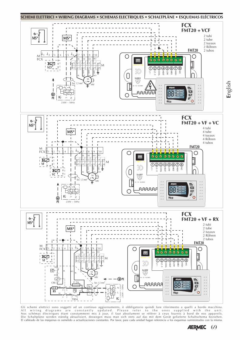
69
Engl
ish
SCHEMI ELETTRICI • WIRING DIAGRAMS • SCHEMAS ELECTRIQUES • SCHALTPLÄNE • ESQUEMAS ELÉCTRICOS
����������
��
�� �
���
�
���
�
����
�
������
���������� �����
�0���
0�8
�
� � � � � � � ��
�
�
� �
�
�
�
�
�
�
���(�,���-.
� #�5
$3.4��������
���
�(
� #) �� /"
� #) �� /"
��
��
�
�)�
�0#
0�8
����
����������
��
���
���
�
���
�
����
�
������
���������� �����
�0���
0�8
�
� � � � � � � ��
�
�
� �
�
�
�
�
�
�
���(�,���-.
� #�5
$3.4��������
��
��
�(
� #) �� /"
� #) �� /"
��
��
�
�)�
�0#
0�8
����
����������
��
���
���
�
���
�
����
�
������
���������� �����
�0���
0�8
���(
�,��
�-.
�
� � � � �
�
#
� � ��
�
�
� �
�
�
�
�
�
�
�� �
#����
�
� �
#)
#)
�
/"
�/"
/"
#)
#)
#)
��
�5
$3.4��������
&$/�
�/)
�(
�
�
�
�
��
� #) �� /"
� #) �� /"
��
��
�
�)�
�0#
0�8
����
Gli schemi elettrici sono soggetti ad un continuo aggiornamento, è obbligatorio quindi fare riferimento a quelli a bordo macchina.A l l w i r i n g d i a g r a m s a r e c o n s t a n t l y u p d a t e d . P l e a s e r e f e r t o t h e o n e s s u p p l i e d w i t h t h e u n i t .Nos schémas électr iques étant constamment mis à jour, i l faut absolument se référer à ceux fournis à bord de nos apparei ls .Die Schaltpläne werden ständig aktualisiert, deswegen muss man sich stets auf das mit dem Gerät gelieferte Schaltschema beziehen.El cableado de las máquinas es sometido a actualizaciones constantes. Por favor, para cada unidad hagan referencia a los esquemas suministrados con la misma.
FCX FMT20 + VCF
2 tubi 2 tube 2 tuyaux 2 Röhren 2 tubos
FCX FMT20 + VF + VC
4 tubi 4 tube 4 tuyaux 4 Röhren 4 tubos
FCX FMT20 + VF + RX
2 tubi 2 tube 2 tuyaux 2 Röhren 2 tubos

70
Engl
ish
���)
�� � � � � � � ��
���(�,���-.
�
#
�)
01
!�
�
��1�$�2
�
$/
��
9�����
9�� � 0�0�
� �
0�
:�
��
�$�
�
�
� �
�
�
�
�
�
�
�(
��
��
�
�)�
�0#
� #) �� /"
� #) �� /"
�#
*#
� � 2 $ & ) /
� � � �#) �
�/"$
(�'�
FCX PPC
SCHEMI ELETTRICI • WIRING DIAGRAMS • SCHEMAS ELECTRIQUES • SCHALTPLÄNE • ESQUEMAS ELÉCTRICOS
Gli schemi elettrici sono soggetti ad un continuo aggiornamento, è obbligatorio quindi fare riferimento a quelli a bordo macchina.A l l w i r i n g d i a g r a m s a r e c o n s t a n t l y u p d a t e d . P l e a s e r e f e r t o t h e o n e s s u p p l i e d w i t h t h e u n i t .Nos schémas électriques étant constamment mis à jour, i l faut absolument se référer à ceux fournis à bord de nos appareils.Die Schaltpläne werden ständig aktualisiert, deswegen muss man sich stets auf das mit dem Gerät gelieferte Schaltschema beziehen.El cableado de las máquinas es sometido a actualizaciones constantes. Por favor, para cada unidad hagan referencia a los esquemas suministrados con la misma.

71
Engl
ish
SCHEMI ELETTRICI • WIRING DIAGRAMS • SCHEMAS ELECTRIQUES • SCHALTPLÄNE • ESQUEMAS ELÉCTRICOS
���(
�,��
�-.
�
/$
�)01
����
���
���
�
����
(�(�(�
(� (� (��-� # #
$0&�
*� *�
*� *�
����
����
(� (� (�
(�(�(� �#
#
�-
������
���
�$��
�����
�$
�$��
�����
(� (� (�
(�(�(� �#
#
�-
������
���
�$��
�����
�$
��
��
�
��
��
�#*#
��
2$
&)
/
��
�
�#
) �
�
/"
$
� �
�� �
� �
� �
�
��
��
��
�
�
��
�#*#
��
2$
&)
/
��
�
�#
)
�
� �
�� �
� �
� �
�
���
)
!�
�
��1�$�2
�
$ / ��
9�����
9�� � 0�0�
� �
0�
:�
��
�$�
(�
'�(
�'�
�
/"
$
����
���
���
�
����
����
���
�
0�������
����
����
/$
/$
�(
�(
��
���
�)�
�0#
��
���
�)�
�0#
�
#)
��
/"
�
#)
��
/"
�
#)
��
/"
�
#)
��
/"
FCX PPCPXAESIT3 + SIT5
Gli schemi elettrici sono soggetti ad un continuo aggiornamento, è obbligatorio quindi fare riferimento a quelli a bordo macchina.A l l w i r i n g d i a g r a m s a r e c o n s t a n t l y u p d a t e d . P l e a s e r e f e r t o t h e o n e s s u p p l i e d w i t h t h e u n i t .Nos schémas électriques étant constamment mis à jour, i l faut absolument se référer à ceux fournis à bord de nos appareils.Die Schaltpläne werden ständig aktualisiert, deswegen muss man sich stets auf das mit dem Gerät gelieferte Schaltschema beziehen.El cableado de las máquinas es sometido a actualizaciones constantes. Por favor, para cada unidad hagan referencia a los esquemas suministrados con la misma.
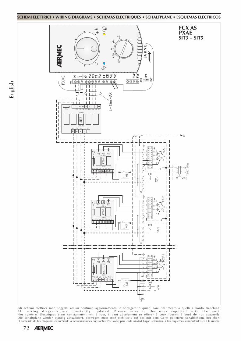
72
Engl
ish
SCHEMI ELETTRICI • WIRING DIAGRAMS • SCHEMAS ELECTRIQUES • SCHALTPLÄNE • ESQUEMAS ELÉCTRICOS
���(
�,��
�-.
��
��
��
�
#
��
��
�)
(�
- 01
��
��
��
�
�
��
(�
-
��
���
'���
�'�
(�(�(�
(� (� (��-� # #
$0&�
*� *�
*� *�
����
��
��
��
�
�
��
(�
-
���
'#
��
�(
�
#)
��
/"�0#
�)�
���
� �
�� �
� �
� �
� �
#)
��
/"
(� (� (�
(�(�(� �#
#
�-
$0&�
'�
���
0#�2&
"2&�2&
�$
�$
0#�2&
"2&�2&
(� (� (�
(�(�(� �#
#
�-
$0&�
'�
���
0#�2&
"2&�2&
(� (� (�
(�(�(� �#
#
�-
$0&�
'��
���
0#�2&
"2&�2&
�$
��
�(
�
#)
��
/"�0#
�)�
���
� �
�� �
� �
� �
� �
#)
��
/"
��
�(
�
#)
��
/"�0#
�)�
���
� �
�� �
� �
� �
� �
#)
��
/"
�����
����
��
���
)
!�
��1�$�2
$ / ��
9�����
9�� � 0�0�
� �
0�
:�
��
�$�
Gli schemi elettrici sono soggetti ad un continuo aggiornamento, è obbligatorio quindi fare riferimento a quelli a bordo macchina.A l l w i r i n g d i a g r a m s a r e c o n s t a n t l y u p d a t e d . P l e a s e r e f e r t o t h e o n e s s u p p l i e d w i t h t h e u n i t .Nos schémas électr iques étant constamment mis à jour, i l faut absolument se référer à ceux fournis à bord de nos apparei ls .Die Schaltpläne werden ständig aktualisiert, deswegen muss man sich stets auf das mit dem Gerät gelieferte Schaltschema beziehen.El cableado de las máquinas es sometido a actualizaciones constantes. Por favor, para cada unidad hagan referencia a los esquemas suministrados con la misma.
FCX ASPXAESIT3 + SIT5
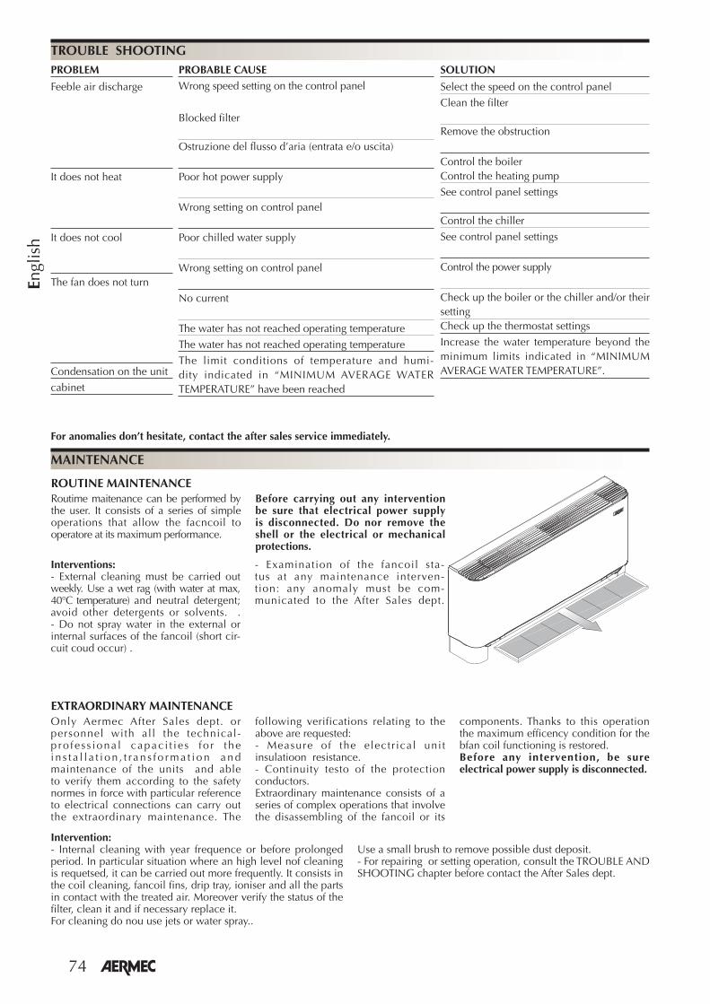
74
Engl
ish
PROBLEM
Feeble air discharge
It does not heat
It does not cool
The fan does not turn
Condensation on the unit
cabinet
PROBABLE CAUSE
Wrong speed setting on the control panel
Blocked filter
Ostruzione del flusso d’aria (entrata e/o uscita)
Poor hot power supply
Wrong setting on control panel
Poor chilled water supply
Wrong setting on control panel
No current
The water has not reached operating temperature
The water has not reached operating temperature
The limit conditions of temperature and humi-dity indicated in “MINIMUM AVERAGE WATER TEMPERATURE” have been reached
SOLUTION
Select the speed on the control panel
Clean the filter
Remove the obstruction
Control the boilerControl the heating pump
See control panel settings
Control the chiller
See control panel settings
Control the power supply
Check up the boiler or the chiller and/or their settingCheck up the thermostat settings
Increase the water temperature beyond the minimum limits indicated in “MINIMUM AVERAGE WATER TEMPERATURE”.
For anomalies don’t hesitate, contact the after sales service immediately.
TROUBLE SHOOTING
Interventions:- External cleaning must be carried out weekly. Use a wet rag (with water at max, 40°C temperature) and neutral detergent; avoid other detergents or solvents. . - Do not spray water in the external or internal surfaces of the fancoil (short cir-cuit coud occur) .
- Examination of the fancoil sta-tus at any maintenance interven-tion: any anomaly must be com-municated to the After Sales dept.
MAINTENANCE
Routime maitenance can be performed by the user. It consists of a series of simple operations that allow the facncoil to operatore at its maximum performance.
Before carrying out any intervention be sure that electrical power supply is disconnected. Do nor remove the shell or the electrical or mechanical protections.
Intervention:- Internal cleaning with year frequence or before prolonged period. In particular situation where an high level nof cleaning is requetsed, it can be carried out more frequently. It consists in the coil cleaning, fancoil fins, drip tray, ioniser and all the parts in contact with the treated air. Moreover verify the status of the filter, clean it and if necessary replace it. For cleaning do nou use jets or water spray..
Use a small brush to remove possible dust deposit. - For repairing or setting operation, consult the TROUBLE AND SHOOTING chapter before contact the After Sales dept.
Only Aermec After Sales dept. or personnel with all the technical-p ro fes s iona l capac i t i e s fo r the i n s t a l l a t i on , t r an s f o rma t i on and maintenance of the units and able to verify them according to the safety normes in force with particular reference to electrical connections can carry out the extraordinary maintenance. The
following verifications relating to the above are requested: - Measure of the electr ical unit insulatioon resistance. - Continuity testo of the protection conductors. Extraordinary maintenance consists of a series of complex operations that involve the disassembling of the fancoil or its
components. Thanks to this operation the maximum efficency condition for the bfan coil functioning is restored.Before any intervention, be sure electrical power supply is disconnected.
ROUTINE MAINTENANCE
EXTRAORDINARY MAINTENANCE

Aermec partecipa al Programma di Certificazione EUROVENT. I prodotti interessati figurano nella Guida EUROVENT dei Prodotti Certificati.
Aermec is partecipating in the EUROVENT Certification Programme. Products are as listed in the EUROVENT Directory of Certified Products.
Aermec partecipe au Programme de Certification EUROVENT. Les produits figurent dans l’Annuaire EUROVENT des Produits Certifiés.
Aermec ist am Zertifikations - Programm EUROVENT beteiligt. Die entsprechend gekennzeichneten Produkte sind im EUROVENT - Jahrbuch aufgefürt.
AERMEC S.p.A. participa en el programa de certificación EUROVENT. Sus equipos aparecen en el directorio de productos certificados EUROVENT.


![Technisches Handbuch FCX - AermecFCX DE Die AERMEC-Einheiten FCX wurden ] v m ] v u u µ v P u ] v Z-nischen Standards und den aner-kannten Sicherheitsregeln gebaut. Sie wurden für](https://img.pdfslide.net/doc/110x75/5e9863b0c424bc6ed060d348/technisches-handbuch-fcx-aermec-fcx-de-die-aermec-einheiten-fcx-wurden-v-m-.jpg)