Embed Size (px)
Citation preview

AeroprecisionC.O.P. Kit Manual
Proof 6
09 // 03 // 2013

Carbine
3Aeroprecision | C.O.P. Kit Manual
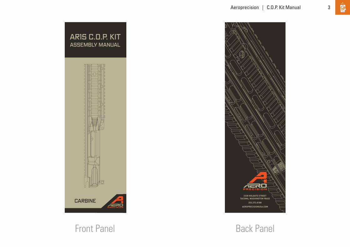
Front Panel Back Panel
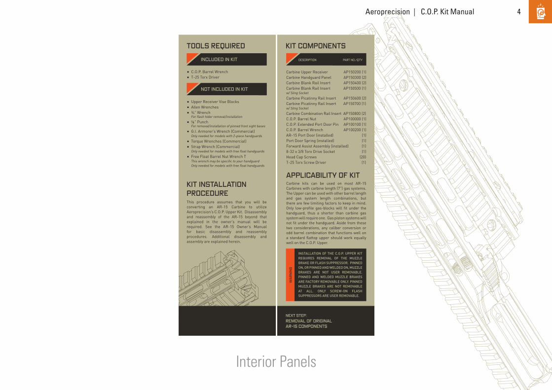
Carbine kits can be used on most AR-15 Carbines with carbine length (6”) gas systems. The Upper can be used with other barrel length and gas system length combinations, but there are few limiting factors to keep in mind. Only low-profile gas-blocks will fit under the handguard, thus a shorter than carbine gas system will require one. Gas piston systems will not fit under the handguard. Aside from these two considerations, any caliber conversion or odd barrel combination that functions well on a standard flattop upper should work equally well on the C.O.P. Upper.
• •
• • • • • • • •
This procedure assumes that you will be converting an AR-15 Carbine to utilize Aeroprecision’s C.O.P. Upper Kit. Disassembly and reassembly of the AR-15 beyond that explained in the owner’s manual will be required. See the AR-15 Owner’s Manual for basic disassembly and reassembly procedures. Additional disassembly and assembly are explained herein.
Carbine Upper Receiver AP15051 1Carbine Handguard Panel AP15052 2Carbine Blank Rail Insert AP15053 2Carbine Blank Rail Insert AP15054 1with Sling Socket Carbine Picatinny Rail Insert AP15055 2Carbine Picatinny Rail Insert AP15056 1with Sling Socket Carbine Combination AP15057 2Rail Insert C.O.P. Barrel Nut AP15058 1C.O.P. Extended Port Door Pin AP15059 1C.O.P. Barrel Wrench AP15080 1AR-15 Port Door (installed) 1Port Door Spring (installed) 1Forward Assist Assembly (installed) 18-32 x 3/8 Torx Drive Socket 1Head Cap Screws 20T-25 Torx Screw Driver 1
2338 HOLGATE STREETTACOMA, WASHINGTON 98402
253.272.8188
AEROPRECISIONUSA.COM
TOOLS REQUIRED
KIT INSTALLATION PROCEDURE
APPLICABILITY OF KIT
KIT COMPONENTS
!
!
REMOVAL OF ORIGINAL AR-15 COMPONENTS
PLACE the safety selector on “SAFE.”
REMOVE the flash hider using a ¾” wrench.
IF the firearm has two-piece handguards, remove them in accordance with the owner’s manual.
LOOK at the front sight base/gas block. If it is pinned onto the barrel, drive out the two pins with a 1/8” punch. If it is held to the barrel with screws, loosen the retaining screws. Then slide/tap the base and gas tube assembly forward until it comes free.
CLOSE the ejection port door. Clamp the upper receiver into a vise using the universal vise blocks. Be careful to use the minimum amount of clamping force needed to retain the upper receiver. If your carbine has a free float handguard, use a strap wrench to grasp the handguard lock ring at the front of the receiver. Loosen the ring by rotating it counterclockwise as viewed from the butt and pull forward on the handguard at the same time. Wiggling the handguard slightly as it loosens may help.
REMOVE the handguard lock ring, handguard, barrel nut, and barrel from the receiver. If your firearm had two piece handguards, use the G.I. Armorer’s wrench to remove the barrel nut. If it had a free float handguard, use the free float handguard barrel nut wrench.
REMOVE the magazine by pressing the magazine catch button and pulling the magazine down and out of the receiver. Remove the magazine and all sources of ammunition from the work area.
EXTRACT the cartridge (if any) from the chamber. To extract a cartridge pull the bolt carrier assembly fully to the rear. If there is a cartridge in the chamber, it should be extracted and ejected from the firearm.
LOOK into the chamber to assure that it does not contain a cartridge.REMOVE the upper receiver assembly
from the lower receiver assembly as directed in your owner’s manual. Then remove the bolt carrier assembly and charging handle from the upper receiver assembly.
ALWAYS ASSUME ALL FIREARMS ARE LOADED. ANYTIME YOU HANDLE A FIREARM, YOU SHOULD IMMEDIATELY INSPECT IT TO ASSURE THAT IT IS COMPLETELY UNLOADED.
THE MAGAZINE WILL FALL FREE WHEN THE MAGAZINE CATCH IS PRESSED. DON’T ALLOW THE MAGAZINE TO FALL ONTO A HARD SURFACE. DOING SO MAY DAMAGE THE MAGAZINE.
INSTALLATION OF THE C.O.P. UPPER KIT REQUIRES REMOVAL OF THE MUZZLE BRAKE OR FLASH SUPPRESSOR. PINNED ON, OR PINNED AND WELDED ON, MUZZLE BRAKES ARE NOT USER REMOVABLE. PINNED AND WELDED MUZZLE BRAKES ARE FACTORY REMOVABLE ONLY. PINNED MUZZLE BRAKES ARE NOT REMOVABLE AT ALL. ONLY SCREW-ON FLASH SUPPRESSORS ARE USER REMOVABLE.
THE STEPS IN UNLOADING YOUR FIREARM MUST BE FOLLOWED IN THE EXACT ORDER GIVEN. THE MAGAZINE MUST BE REMOVED BEFORE THE CHAMBER IS INSPECTED. IF YOU CLEAR THE CHAMBER BEFORE REMOVING THE MAGAZINE, YOU MAY REMOVE ONE CARTRIDGE FROM THE CHAMBER AND THEN, UPON CLOSING THE BOLT, CHAMBER ANOTHER CARTRIDGE FROM THE MAGAZINE. THE FIREARM WILL STILL BE LOADED. REMEMBER THAT A CARTRIDGE IN THE CHAMBER CAN STILL BE FIRED EVEN AFTER THE MAGAZINE IS REMOVED.
STEP FIVE
STEP SIX
STEP SEVEN
STEP EIGHT
STEP NINE
STEP ONE
STEP TWO
STEP FOUR
WA
RNIN
G
CAU
TION
WA
RNIN
G WA
RNIN
G
3
5
6
7
8
9
1
2
4
INSTALLATION OF THE C.O.P. UPPER KIT REQUIRES REMOVAL OF THE MUZZLE BRAKE OR FLASH SUPPRESSOR. PINNED ON, OR PINNED AND WELDED ON, MUZZLE BRAKES ARE NOT USER REMOVABLE. PINNED AND WELDED MUZZLE BRAKES ARE FACTORY REMOVABLE ONLY. PINNED MUZZLE BRAKES ARE NOT REMOVABLE AT ALL. ONLY SCREW-ON FLASH SUPPRESSORS ARE USER REMOVABLE.
WA
RN
ING
INCLUDED IN KITDESCRIPTION PART NO.
NOT INCLUDED IN KIT
AR15 COP KITASSEMBLY MANUAL
NEXT STEP:INSTALLATION OF C.O.P. UPPER KIT
STEP THREE
NEXT STEP:REMOVAL OF ORIGINAL AR-15 COMPONENTS
C.O.P. Barrel Wrench T-25 Torx Driver
Upper Receiver Vise BlocksAllen Wrenches¾” Wrench For flash hider removal/installation⅟” Punch For removal/installation of pinned front sight basesG.I. Armorer’s Wrench (Commercial) Only needed for models with 2-piece handguardsTorque Wrenches (Commercial)Strap Wrench (Commercial) Only needed for models with free float handguardsFree Float Barrel Nut Wrench TThis wrench may be specific to your handguard Only needed for models with free float handguards
Carbine kits can be used on most AR-15 Carbines with carbine length (7”) gas systems. The Upper can be used with other barrel length and gas system length combinations, but there are few limiting factors to keep in mind. Only low-profile gas-blocks will fit under the handguard, thus a shorter than carbine gas system will require one. Gas piston systems will not fit under the handguard. Aside from these two considerations, any caliber conversion or odd barrel combination that functions well on a standard flattop upper should work equally well on the C.O.P. Upper.
• •
This procedure assumes that you will be converting an AR-15 Carbine to utilize Aeroprecision’s C.O.P. Upper Kit. Disassembly and reassembly of the AR-15 beyond that explained in the owner’s manual will be required. See the AR-15 Owner’s Manual for basic disassembly and reassembly procedures. Additional disassembly and assembly are explained herein.
Carbine Upper Receiver AP150200 (1)Carbine Handguard Panel AP150300 (2)Carbine Blank Rail Insert AP150400 (2)Carbine Blank Rail Insert AP150500 (1)w/ Sling Socket Carbine Picatinny Rail Insert AP150600 (2)Carbine Picatinny Rail Insert AP150700 (1)w/ Sling Socket Carbine Combination Rail Insert AP150800 (2) C.O.P. Barrel Nut AP100000 (1)C.O.P. Extended Port Door Pin AP100100 (1)C.O.P. Barrel Wrench AP100200 (1)AR-15 Port Door (installed) (1)Port Door Spring (installed) (1)Forward Assist Assembly (installed) (1)8-32 x 3/8 Torx Drive Socket (1)Head Cap Screws (20)T-25 Torx Screw Driver (1)
2338 HOLGATE STREETTACOMA, WASHINGTON 98402
253.272.8188
AEROPRECISIONUSA.COM
TOOLS REQUIRED
KIT INSTALLATION PROCEDURE
APPLICABILITY OF KIT
KIT COMPONENTS
!
!
REMOVAL OF ORIGINAL AR-15 COMPONENTS
PLACE the safety selector on “SAFE.”
REMOVE the flash hider using a ¾” wrench.
IF the firearm has two-piece handguards, remove them in accordance with the owner’s manual.
LOOK at the front sight base/gas block. If it is pinned onto the barrel, drive out the two pins with a 1/8” punch. If it is held to the barrel with screws, loosen the retaining screws. Then slide/tap the base and gas tube assembly forward until it comes free.
CLOSE the ejection port door. Clamp the upper receiver into a vise using the universal vise blocks. Be careful to use the minimum amount of clamping force needed to retain the upper receiver. If your carbine has a free float handguard, use a strap wrench to grasp the handguard lock ring at the front of the receiver. Loosen the ring by rotating it counterclockwise as viewed from the butt and pull forward on the handguard at the same time. Wiggling the handguard slightly as it loosens may help.
REMOVE the handguard lock ring, handguard, barrel nut, and barrel from the receiver. If your firearm had two piece handguards, use the G.I. Armorer’s wrench to remove the barrel nut. If it had a free float handguard, use the free float handguard barrel nut wrench.
REMOVE the magazine by pressing the magazine catch button and pulling the magazine down and out of the receiver. Remove the magazine and all sources of ammunition from the work area.
EXTRACT the cartridge (if any) from the chamber. To extract a cartridge pull the bolt carrier assembly fully to the rear. If there is a cartridge in the chamber, it should be extracted and ejected from the firearm.
LOOK into the chamber to assure that it does not contain a cartridge.REMOVE the upper receiver assembly
from the lower receiver assembly as directed in your owner’s manual. Then remove the bolt carrier assembly and charging handle from the upper receiver assembly.
ALWAYS ASSUME ALL FIREARMS ARE LOADED. ANYTIME YOU HANDLE A FIREARM, YOU SHOULD IMMEDIATELY INSPECT IT TO ASSURE THAT IT IS COMPLETELY UNLOADED.
THE MAGAZINE WILL FALL FREE WHEN THE MAGAZINE CATCH IS PRESSED. DON’T ALLOW THE MAGAZINE TO FALL ONTO A HARD SURFACE. DOING SO MAY DAMAGE THE MAGAZINE.
INSTALLATION OF THE C.O.P. UPPER KIT REQUIRES REMOVAL OF THE MUZZLE BRAKE OR FLASH SUPPRESSOR. PINNED ON, OR PINNED AND WELDED ON, MUZZLE BRAKES ARE NOT USER REMOVABLE. PINNED AND WELDED MUZZLE BRAKES ARE FACTORY REMOVABLE ONLY. PINNED MUZZLE BRAKES ARE NOT REMOVABLE AT ALL. ONLY SCREW-ON FLASH SUPPRESSORS ARE USER REMOVABLE.
THE STEPS IN UNLOADING YOUR FIREARM MUST BE FOLLOWED IN THE EXACT ORDER GIVEN. THE MAGAZINE MUST BE REMOVED BEFORE THE CHAMBER IS INSPECTED. IF YOU CLEAR THE CHAMBER BEFORE REMOVING THE MAGAZINE, YOU MAY REMOVE ONE CARTRIDGE FROM THE CHAMBER AND THEN, UPON CLOSING THE BOLT, CHAMBER ANOTHER CARTRIDGE FROM THE MAGAZINE. THE FIREARM WILL STILL BE LOADED. REMEMBER THAT A CARTRIDGE IN THE CHAMBER CAN STILL BE FIRED EVEN AFTER THE MAGAZINE IS REMOVED.
STEP FIVE
STEP SIX
STEP SEVEN
STEP EIGHT
STEP NINE
STEP ONE
STEP TWO
STEP FOUR
WA
RNIN
G
CAU
TION
WA
RNIN
G WA
RNIN
G
3
5
6
7
8
9
1
2
4
INSTALLATION OF THE C.O.P. UPPER KIT REQUIRES REMOVAL OF THE MUZZLE BRAKE OR FLASH SUPPRESSOR. PINNED ON, OR PINNED AND WELDED ON, MUZZLE BRAKES ARE NOT USER REMOVABLE. PINNED AND WELDED MUZZLE BRAKES ARE FACTORY REMOVABLE ONLY. PINNED MUZZLE BRAKES ARE NOT REMOVABLE AT ALL. ONLY SCREW-ON FLASH SUPPRESSORS ARE USER REMOVABLE.
WA
RN
ING
INCLUDED IN KITDESCRIPTION
NOT INCLUDED IN KIT
AR15 C.O.P. KITASSEMBLY MANUAL
CARBINE
NEXT STEP:INSTALLATION OF C.O.P. UPPER KIT
STEP THREE
NEXT STEP:REMOVAL OF ORIGINAL AR-15 COMPONENTS
C.O.P. Barrel Wrench T-25 Torx Driver
Upper Receiver Vise BlocksAllen Wrenches¾” Wrench For flash hider removal/installation ” Punch For removal/installation of pinned front sight basesG.I. Armorer’s Wrench (Commercial) Only needed for models with 2-piece handguardsTorque Wrenches (Commercial)Strap Wrench (Commercial) Only needed for models with free float handguardsFree Float Barrel Nut Wrench TThis wrench may be specific to your handguard Only needed for models with free float handguards
•
•
•
•
•
•
•
•
PART NO./QTY
4Aeroprecision | C.O.P. Kit Manual
Interior Panels
Carbine kits can be used on most AR-15 Carbines with carbine length (7”) gas systems. The Upper can be used with other barrel length and gas system length combinations, but there are few limiting factors to keep in mind. Only low-profile gas-blocks will fit under the handguard, thus a shorter than carbine gas system will require one. Gas piston systems will not fit under the handguard. Aside from these two considerations, any caliber conversion or odd barrel combination that functions well on a standard flattop upper should work equally well on the C.O.P. Upper.
• •
This procedure assumes that you will be converting an AR-15 Carbine to utilize Aeroprecision’s C.O.P. Upper Kit. Disassembly and reassembly of the AR-15 beyond that explained in the owner’s manual will be required. See the AR-15 Owner’s Manual for basic disassembly and reassembly procedures. Additional disassembly and assembly are explained herein.
Carbine Upper Receiver AP150200 (1)Carbine Handguard Panel AP150300 (2)Carbine Blank Rail Insert AP150400 (2)Carbine Blank Rail Insert AP150500 (1)w/ Sling Socket Carbine Picatinny Rail Insert AP150600 (2)Carbine Picatinny Rail Insert AP150700 (1)w/ Sling Socket Carbine Combination Rail Insert AP150800 (2) C.O.P. Barrel Nut AP100000 (1)C.O.P. Extended Port Door Pin AP100100 (1)C.O.P. Barrel Wrench AP100200 (1)AR-15 Port Door (installed) (1)Port Door Spring (installed) (1)Forward Assist Assembly (installed) (1)8-32 x 3/8 Torx Drive Socket (1)Head Cap Screws (20)T-25 Torx Screw Driver (1)
2338 HOLGATE STREETTACOMA, WASHINGTON 98402
253.272.8188
AEROPRECISIONUSA.COM
TOOLS REQUIRED
KIT INSTALLATION PROCEDURE
APPLICABILITY OF KIT
KIT COMPONENTS
!
!
REMOVAL OF ORIGINAL AR-15 COMPONENTS
PLACE the safety selector on “SAFE.”
REMOVE the flash hider using a ¾” wrench.
IF the firearm has two-piece handguards, remove them in accordance with the owner’s manual.
LOOK at the front sight base/gas block. If it is pinned onto the barrel, drive out the two pins with a 1/8” punch. If it is held to the barrel with screws, loosen the retaining screws. Then slide/tap the base and gas tube assembly forward until it comes free.
CLOSE the ejection port door. Clamp the upper receiver into a vise using the universal vise blocks. Be careful to use the minimum amount of clamping force needed to retain the upper receiver. If your carbine has a free float handguard, use a strap wrench to grasp the handguard lock ring at the front of the receiver. Loosen the ring by rotating it counterclockwise as viewed from the butt and pull forward on the handguard at the same time. Wiggling the handguard slightly as it loosens may help.
REMOVE the handguard lock ring, handguard, barrel nut, and barrel from the receiver. If your firearm had two piece handguards, use the G.I. Armorer’s wrench to remove the barrel nut. If it had a free float handguard, use the free float handguard barrel nut wrench.
REMOVE the magazine by pressing the magazine catch button and pulling the magazine down and out of the receiver. Remove the magazine and all sources of ammunition from the work area.
EXTRACT the cartridge (if any) from the chamber. To extract a cartridge pull the bolt carrier assembly fully to the rear. If there is a cartridge in the chamber, it should be extracted and ejected from the firearm.
LOOK into the chamber to assure that it does not contain a cartridge.REMOVE the upper receiver assembly
from the lower receiver assembly as directed in your owner’s manual. Then remove the bolt carrier assembly and charging handle from the upper receiver assembly.
ALWAYS ASSUME ALL FIREARMS ARE LOADED. ANYTIME YOU HANDLE A FIREARM, YOU SHOULD IMMEDIATELY INSPECT IT TO ASSURE THAT IT IS COMPLETELY UNLOADED.
THE MAGAZINE WILL FALL FREE WHEN THE MAGAZINE CATCH IS PRESSED. DON’T ALLOW THE MAGAZINE TO FALL ONTO A HARD SURFACE. DOING SO MAY DAMAGE THE MAGAZINE.
INSTALLATION OF THE C.O.P. UPPER KIT REQUIRES REMOVAL OF THE MUZZLE BRAKE OR FLASH SUPPRESSOR. PINNED ON, OR PINNED AND WELDED ON, MUZZLE BRAKES ARE NOT USER REMOVABLE. PINNED AND WELDED MUZZLE BRAKES ARE FACTORY REMOVABLE ONLY. PINNED MUZZLE BRAKES ARE NOT REMOVABLE AT ALL. ONLY SCREW-ON FLASH SUPPRESSORS ARE USER REMOVABLE.
THE STEPS IN UNLOADING YOUR FIREARM MUST BE FOLLOWED IN THE EXACT ORDER GIVEN. THE MAGAZINE MUST BE REMOVED BEFORE THE CHAMBER IS INSPECTED. IF YOU CLEAR THE CHAMBER BEFORE REMOVING THE MAGAZINE, YOU MAY REMOVE ONE CARTRIDGE FROM THE CHAMBER AND THEN, UPON CLOSING THE BOLT, CHAMBER ANOTHER CARTRIDGE FROM THE MAGAZINE. THE FIREARM WILL STILL BE LOADED. REMEMBER THAT A CARTRIDGE IN THE CHAMBER CAN STILL BE FIRED EVEN AFTER THE MAGAZINE IS REMOVED.
STEP FIVE
STEP SIX
STEP SEVEN
STEP EIGHT
STEP NINE
STEP ONE
STEP TWO
STEP FOUR
WA
RNIN
G
CAU
TION
WA
RNIN
G WA
RNIN
G
3
5
6
7
8
9
1
2
4
INSTALLATION OF THE C.O.P. UPPER KIT REQUIRES REMOVAL OF THE MUZZLE BRAKE OR FLASH SUPPRESSOR. PINNED ON, OR PINNED AND WELDED ON, MUZZLE BRAKES ARE NOT USER REMOVABLE. PINNED AND WELDED MUZZLE BRAKES ARE FACTORY REMOVABLE ONLY. PINNED MUZZLE BRAKES ARE NOT REMOVABLE AT ALL. ONLY SCREW-ON FLASH SUPPRESSORS ARE USER REMOVABLE.
WA
RN
ING
INCLUDED IN KITDESCRIPTION
NOT INCLUDED IN KIT
AR15 C.O.P. KITASSEMBLY MANUAL
CARBINE
NEXT STEP:INSTALLATION OF C.O.P. UPPER KIT
STEP THREE
NEXT STEP:REMOVAL OF ORIGINAL AR-15 COMPONENTS
C.O.P. Barrel Wrench T-25 Torx Driver
Upper Receiver Vise BlocksAllen Wrenches¾” Wrench For flash hider removal/installation ” Punch For removal/installation of pinned front sight basesG.I. Armorer’s Wrench (Commercial) Only needed for models with 2-piece handguardsTorque Wrenches (Commercial)Strap Wrench (Commercial) Only needed for models with free float handguardsFree Float Barrel Nut Wrench TThis wrench may be specific to your handguard Only needed for models with free float handguards
•
•
•
•
•
•
•
•
PART NO./QTY

5Aeroprecision | C.O.P. Kit Manual
Interior Page
Carbine kits can be used on most AR-15 Carbines with carbine length (6”) gas systems. The Upper can be used with other barrel length and gas system length combinations, but there are few limiting factors to keep in mind. Only low-profile gas-blocks will fit under the handguard, thus a shorter than carbine gas system will require one. Gas piston systems will not fit under the handguard. Aside from these two considerations, any caliber conversion or odd barrel combination that functions well on a standard flattop upper should work equally well on the C.O.P. Upper.
• •
• • • • • • • •
This procedure assumes that you will be converting an AR-15 Carbine to utilize Aeroprecision’s C.O.P. Upper Kit. Disassembly and reassembly of the AR-15 beyond that explained in the owner’s manual will be required. See the AR-15 Owner’s Manual for basic disassembly and reassembly procedures. Additional disassembly and assembly are explained herein.
Carbine Upper Receiver AP15051 1Carbine Handguard Panel AP15052 2Carbine Blank Rail Insert AP15053 2Carbine Blank Rail Insert AP15054 1with Sling Socket Carbine Picatinny Rail Insert AP15055 2Carbine Picatinny Rail Insert AP15056 1with Sling Socket Carbine Combination AP15057 2Rail Insert C.O.P. Barrel Nut AP15058 1C.O.P. Extended Port Door Pin AP15059 1C.O.P. Barrel Wrench AP15080 1AR-15 Port Door (installed) 1Port Door Spring (installed) 1Forward Assist Assembly (installed) 18-32 x 3/8 Torx Drive Socket 1Head Cap Screws 20T-25 Torx Screw Driver 1
2338 HOLGATE STREETTACOMA, WASHINGTON 98402
253.272.8188
AEROPRECISIONUSA.COM
TOOLS REQUIRED
KIT INSTALLATION PROCEDURE
APPLICABILITY OF KIT
KIT COMPONENTS
!
!
REMOVAL OF ORIGINAL AR-15 COMPONENTS
PLACE the safety selector on “SAFE.”
REMOVE the flash hider using a ¾” wrench.
IF the firearm has two-piece handguards, remove them in accordance with the owner’s manual.
LOOK at the front sight base/gas block. If it is pinned onto the barrel, drive out the two pins with a 1/8” punch. If it is held to the barrel with screws, loosen the retaining screws. Then slide/tap the base and gas tube assembly forward until it comes free.
CLOSE the ejection port door. Clamp the upper receiver into a vise using the universal vise blocks. Be careful to use the minimum amount of clamping force needed to retain the upper receiver. If your carbine has a free float handguard, use a strap wrench to grasp the handguard lock ring at the front of the receiver. Loosen the ring by rotating it counterclockwise as viewed from the butt and pull forward on the handguard at the same time. Wiggling the handguard slightly as it loosens may help.
REMOVE the handguard lock ring, handguard, barrel nut, and barrel from the receiver. If your firearm had two piece handguards, use the G.I. Armorer’s wrench to remove the barrel nut. If it had a free float handguard, use the free float handguard barrel nut wrench.
REMOVE the magazine by pressing the magazine catch button and pulling the magazine down and out of the receiver. Remove the magazine and all sources of ammunition from the work area.
EXTRACT the cartridge (if any) from the chamber. To extract a cartridge pull the bolt carrier assembly fully to the rear. If there is a cartridge in the chamber, it should be extracted and ejected from the firearm.
LOOK into the chamber to assure that it does not contain a cartridge. REMOVE the upper receiver assembly
from the lower receiver assembly as directed in your owner’s manual. Then remove the bolt carrier assembly and charging handle from the upper receiver assembly.
ALWAYS ASSUME ALL FIREARMS ARE LOADED. ANYTIME YOU HANDLE A FIREARM, YOU SHOULD IMMEDIATELY INSPECT IT TO ASSURE THAT IT IS COMPLETELY UNLOADED.
THE MAGAZINE WILL FALL FREE WHEN THE MAGAZINE CATCH IS PRESSED. DON’T ALLOW THE MAGAZINE TO FALL ONTO A HARD SURFACE. DOING SO MAY DAMAGE THE MAGAZINE.
INSTALLATION OF THE C.O.P. UPPER KIT REQUIRES REMOVAL OF THE MUZZLE BRAKE OR FLASH SUPPRESSOR. PINNED ON, OR PINNED AND WELDED ON, MUZZLE BRAKES ARE NOT USER REMOVABLE. PINNED AND WELDED MUZZLE BRAKES ARE FACTORY REMOVABLE ONLY. PINNED MUZZLE BRAKES ARE NOT REMOVABLE AT ALL. ONLY SCREW-ON FLASH SUPPRESSORS ARE USER REMOVABLE.
THE STEPS IN UNLOADING YOUR FIREARM MUST BE FOLLOWED IN THE EXACT ORDER GIVEN. THE MAGAZINE MUST BE REMOVED BEFORE THE CHAMBER IS INSPECTED. IF YOU CLEAR THE CHAMBER BEFORE REMOVING THE MAGAZINE, YOU MAY REMOVE ONE CARTRIDGE FROM THE CHAMBER AND THEN, UPON CLOSING THE BOLT, CHAMBER ANOTHER CARTRIDGE FROM THE MAGAZINE. THE FIREARM WILL STILL BE LOADED. REMEMBER THAT A CARTRIDGE IN THE CHAMBER CAN STILL BE FIRED EVEN AFTER THE MAGAZINE IS REMOVED.
STEP FIVE
STEP SIX
STEP SEVEN
STEP EIGHT
STEP NINE
STEP ONE
STEP TWO
STEP FOUR
WA
RNIN
G
CAU
TIO
N
WA
RNIN
G WA
RNIN
G
3
5
6
7
8
9
1
2
4
INSTALLATION OF THE C.O.P. UPPER KIT REQUIRES REMOVAL OF THE MUZZLE BRAKE OR FLASH SUPPRESSOR. PINNED ON, OR PINNED AND WELDED ON, MUZZLE BRAKES ARE NOT USER REMOVABLE. PINNED AND WELDED MUZZLE BRAKES ARE FACTORY REMOVABLE ONLY. PINNED MUZZLE BRAKES ARE NOT REMOVABLE AT ALL. ONLY SCREW-ON FLASH SUPPRESSORS ARE USER REMOVABLE.
WA
RN
ING
INCLUDED IN KIT DESCRIPTIONPART NO.
NOT INCLUDED IN KIT
AR15 COP KITASSEMBLY MANUAL
NEXT STEP:INSTALLATION OF C.O.P. UPPER KIT
STEP THREE
NEXT STEP:REMOVAL OF ORIGINAL AR-15 COMPONENTS
C.O.P. Barrel Wrench T-25 Torx Driver
Upper Receiver Vise BlocksAllen Wrenches¾” Wrench For flash hider removal/installation⅟” Punch For removal/installation of pinned front sight basesG.I. Armorer’s Wrench (Commercial) Only needed for models with 2-piece handguardsTorque Wrenches (Commercial)Strap Wrench (Commercial) Only needed for models with free float handguardsFree Float Barrel Nut Wrench TThis wrench may be specific to your handguard Only needed for models with free float handguards
Carbine kits can be used on most AR-15 Carbines with carbine length (7”) gas systems. The Upper can be used with other barrel length and gas system length combinations, but there are few limiting factors to keep in mind. Only low-profile gas-blocks will fit under the handguard, thus a shorter than carbine gas system will require one. Gas piston systems will not fit under the handguard. Aside from these two considerations, any caliber conversion or odd barrel combination that functions well on a standard flattop upper should work equally well on the C.O.P. Upper.
• •
This procedure assumes that you will be converting an AR-15 Carbine to utilize Aeroprecision’s C.O.P. Upper Kit. Disassembly and reassembly of the AR-15 beyond that explained in the owner’s manual will be required. See the AR-15 Owner’s Manual for basic disassembly and reassembly procedures. Additional disassembly and assembly are explained herein.
Carbine Upper Receiver AP150200 (1)Carbine Handguard Panel AP150300 (2)Carbine Blank Rail Insert AP150400 (2)Carbine Blank Rail Insert AP150500 (1)w/ Sling Socket Carbine Picatinny Rail Insert AP150600 (2)Carbine Picatinny Rail Insert AP150700 (1)w/ Sling Socket Carbine Combination Rail Insert AP150800 (2) C.O.P. Barrel Nut AP100000 (1)C.O.P. Extended Port Door Pin AP100100 (1)C.O.P. Barrel Wrench AP100200 (1)AR-15 Port Door (installed) (1)Port Door Spring (installed) (1)Forward Assist Assembly (installed) (1)8-32 x 3/8 Torx Drive Socket (1)Head Cap Screws (20)T-25 Torx Screw Driver (1)
2338 HOLGATE STREETTACOMA, WASHINGTON 98402
253.272.8188
AEROPRECISIONUSA.COM
TOOLS REQUIRED
KIT INSTALLATION PROCEDURE
APPLICABILITY OF KIT
KIT COMPONENTS
!
!
REMOVAL OF ORIGINAL AR-15 COMPONENTS
PLACE the safety selector on “SAFE.”
REMOVE the flash hider using a ¾” wrench.
IF the firearm has two-piece handguards, remove them in accordance with the owner’s manual.
LOOK at the front sight base/gas block. If it is pinned onto the barrel, drive out the two pins with a 1/8” punch. If it is held to the barrel with screws, loosen the retaining screws. Then slide/tap the base and gas tube assembly forward until it comes free.
CLOSE the ejection port door. Clamp the upper receiver into a vise using the universal vise blocks. Be careful to use the minimum amount of clamping force needed to retain the upper receiver. If your carbine has a free float handguard, use a strap wrench to grasp the handguard lock ring at the front of the receiver. Loosen the ring by rotating it counterclockwise as viewed from the butt and pull forward on the handguard at the same time. Wiggling the handguard slightly as it loosens may help.
REMOVE the handguard lock ring, handguard, barrel nut, and barrel from the receiver. If your firearm had two piece handguards, use the G.I. Armorer’s wrench to remove the barrel nut. If it had a free float handguard, use the free float handguard barrel nut wrench.
REMOVE the magazine by pressing the magazine catch button and pulling the magazine down and out of the receiver. Remove the magazine and all sources of ammunition from the work area.
EXTRACT the cartridge (if any) from the chamber. To extract a cartridge pull the bolt carrier assembly fully to the rear. If there is a cartridge in the chamber, it should be extracted and ejected from the firearm.
LOOK into the chamber to assure that it does not contain a cartridge. REMOVE the upper receiver assembly
from the lower receiver assembly as directed in your owner’s manual. Then remove the bolt carrier assembly and charging handle from the upper receiver assembly.
ALWAYS ASSUME ALL FIREARMS ARE LOADED. ANYTIME YOU HANDLE A FIREARM, YOU SHOULD IMMEDIATELY INSPECT IT TO ASSURE THAT IT IS COMPLETELY UNLOADED.
THE MAGAZINE WILL FALL FREE WHEN THE MAGAZINE CATCH IS PRESSED. DON’T ALLOW THE MAGAZINE TO FALL ONTO A HARD SURFACE. DOING SO MAY DAMAGE THE MAGAZINE.
INSTALLATION OF THE C.O.P. UPPER KIT REQUIRES REMOVAL OF THE MUZZLE BRAKE OR FLASH SUPPRESSOR. PINNED ON, OR PINNED AND WELDED ON, MUZZLE BRAKES ARE NOT USER REMOVABLE. PINNED AND WELDED MUZZLE BRAKES ARE FACTORY REMOVABLE ONLY. PINNED MUZZLE BRAKES ARE NOT REMOVABLE AT ALL. ONLY SCREW-ON FLASH SUPPRESSORS ARE USER REMOVABLE.
THE STEPS IN UNLOADING YOUR FIREARM MUST BE FOLLOWED IN THE EXACT ORDER GIVEN. THE MAGAZINE MUST BE REMOVED BEFORE THE CHAMBER IS INSPECTED. IF YOU CLEAR THE CHAMBER BEFORE REMOVING THE MAGAZINE, YOU MAY REMOVE ONE CARTRIDGE FROM THE CHAMBER AND THEN, UPON CLOSING THE BOLT, CHAMBER ANOTHER CARTRIDGE FROM THE MAGAZINE. THE FIREARM WILL STILL BE LOADED. REMEMBER THAT A CARTRIDGE IN THE CHAMBER CAN STILL BE FIRED EVEN AFTER THE MAGAZINE IS REMOVED.
STEP FIVE
STEP SIX
STEP SEVEN
STEP EIGHT
STEP NINE
STEP ONE
STEP TWO
STEP FOUR
WA
RNIN
G
CAU
TIO
N
WA
RNIN
G WA
RNIN
G
3
5
6
7
8
9
1
2
4
INSTALLATION OF THE C.O.P. UPPER KIT REQUIRES REMOVAL OF THE MUZZLE BRAKE OR FLASH SUPPRESSOR. PINNED ON, OR PINNED AND WELDED ON, MUZZLE BRAKES ARE NOT USER REMOVABLE. PINNED AND WELDED MUZZLE BRAKES ARE FACTORY REMOVABLE ONLY. PINNED MUZZLE BRAKES ARE NOT REMOVABLE AT ALL. ONLY SCREW-ON FLASH SUPPRESSORS ARE USER REMOVABLE.
WA
RN
ING
INCLUDED IN KIT DESCRIPTION
NOT INCLUDED IN KIT
AR15 C.O.P. KITASSEMBLY MANUAL
CARBINE
NEXT STEP:INSTALLATION OF C.O.P. UPPER KIT
STEP THREE
NEXT STEP:REMOVAL OF ORIGINAL AR-15 COMPONENTS
C.O.P. Barrel Wrench T-25 Torx Driver
Upper Receiver Vise BlocksAllen Wrenches¾” Wrench For flash hider removal/installation ” Punch For removal/installation of pinned front sight basesG.I. Armorer’s Wrench (Commercial) Only needed for models with 2-piece handguardsTorque Wrenches (Commercial)Strap Wrench (Commercial) Only needed for models with free float handguardsFree Float Barrel Nut Wrench TThis wrench may be specific to your handguard Only needed for models with free float handguards
•
•
•
•
•
•
•
•
PART NO./QTY
6Aeroprecision | C.O.P. Kit Manual
Interior Page
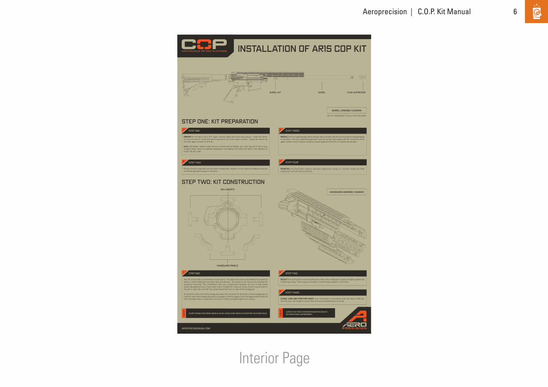
INSTALLATION OF AR15 COP KIT
STEP ONE: KIT PREPARATION
STEP TWO: KIT CONSTRUCTION
GREASE the threads in the C.O.P. upper receiver lightly with heavy duty grease. Install the barrel nut onto the barrel. Install the barrel and barrel nut to the upper receiver. Torque the barrel nut onto the upper receiver to 55 ft-lb.
NOTE: THE BARREL WRENCH MUST BE FULLY SEATED ON THE BARREL NUT LUGS, FAILURE TO DO SO CAN, IN RARE CASES, RESULT IN WRENCH BREAKAGE! THE BARREL NUT DOES NOT NEED TO BE INDEXED TO CLEAR THE GAS TUBE.
INSTALL the front sight base/gas block and gas tube assembly onto the barrel by gently sliding/tapping it into place. The front sight base/gas block must be vertical and aligned with the centerline of the upper receiver. Lock it in place using the screws torqued to 65 in-lbs, or replace the two pins.
IF your firearm originally had two-piece handguards, dispose of the original handguard cap and install the gas block spacer in its place.
REINSTALL the flash hider washers and flash suppressor. Using a ¾” wrench, torque the flash suppressor until its flats are vertical.
ALWAYS TEST FIRE YOUR WEAPON BEFORE USING IN AN OPERATIONAL ENVIRONMENT.
STEP ONE STEP THREE
STEP TWO STEP FOUR
WA
RNIN
G
1 3
2 4
Your kit comes with an assortment of rail inserts. The blank rail inserts are intended for situations where a comfortable grip and clean lines are desired. The picatinny rail inserts are intended for accessory mounting. The combination rails are a compromise between the two. A sling swivel socket equipped version of each style is also included for sling use; these inserts may be used on the left or right side and with the socket toward the front or rear of the handguard.
To install the lower half of the handguard, select the rail insert for the bottom of the handguard and hold the insert and handguard panels arranged so that the edge of each handguard panel with the three threaded holes is toward the rail insert. Install and lightly tighten the screws.
SELECT the rail inserts for the remaining two sides of the handguard. Install and lightly tighten the remaining screws. Then torque all screws in an alternating pattern to 25 in-lbs.
CLEAN, LUBE AND FUNCTION CHECK your mid-length in accordance with the Owner’s Manual. Test fire your mid-length to assure that you have reassembled it correctly.
STEP ONE STEP TWO
STEP THREE
1 2
3
DO NOT TORQUE THE SCREWS ABOVE 40 IN LBS. DOING SO MAY RESULT IN STRIPPING THE SCREW HOLES. CA
UTI
ON
AEROPRECISIONUSA.COM
FLASH SUPPRESSORBARREL
BARREL ASSEMBLY DIAGRAM
HANDGUARD ASSEMBLY DIAGRAM
BARREL NUT
SEE “KIT COMPONENTS” FOR ALL PARTS INCLUDED.
HANDGUARD PANELS
RAIL INSERTS

Mid-Length

8Aeroprecision | C.O.P. Kit Manual
Front Panel Back Panel
Carbine kits can be used on most AR-15 Carbines with carbine length (6”) gas systems. The Upper can be used with other barrel length and gas system length combinations, but there are few limiting factors to keep in mind. Only low-profile gas-blocks will fit under the handguard, thus a shorter than carbine gas system will require one. Gas piston systems will not fit under the handguard. Aside from these two considerations, any caliber conversion or odd barrel combination that functions well on a standard flattop upper should work equally well on the C.O.P. Upper.
• •
• • • • • • • •
This procedure assumes that you will be converting an AR-15 Carbine to utilize Aeroprecision’s C.O.P. Upper Kit. Disassembly and reassembly of the AR-15 beyond that explained in the owner’s manual will be required. See the AR-15 Owner’s Manual for basic disassembly and reassembly procedures. Additional disassembly and assembly are explained herein.
Carbine Upper Receiver AP15051 1Carbine Handguard Panel AP15052 2Carbine Blank Rail Insert AP15053 2Carbine Blank Rail Insert AP15054 1with Sling Socket Carbine Picatinny Rail Insert AP15055 2Carbine Picatinny Rail Insert AP15056 1with Sling Socket Carbine Combination AP15057 2Rail Insert C.O.P. Barrel Nut AP15058 1C.O.P. Extended Port Door Pin AP15059 1C.O.P. Barrel Wrench AP15080 1AR-15 Port Door (installed) 1Port Door Spring (installed) 1Forward Assist Assembly (installed) 18-32 x 3/8 Torx Drive Socket 1Head Cap Screws 20T-25 Torx Screw Driver 1
2338 HOLGATE STREETTACOMA, WASHINGTON 98402
253.272.8188
AEROPRECISIONUSA.COM
TOOLS REQUIRED
KIT INSTALLATION PROCEDURE
APPLICABILITY OF KIT
KIT COMPONENTS
!
!
REMOVAL OF ORIGINAL AR-15 COMPONENTS
PLACE the safety selector on “SAFE.”
REMOVE the flash hider using a ¾” wrench.
IF the firearm has two-piece handguards, remove them in accordance with the owner’s manual.
LOOK at the front sight base/gas block. If it is pinned onto the barrel, drive out the two pins with a 1/8” punch. If it is held to the barrel with screws, loosen the retaining screws. Then slide/tap the base and gas tube assembly forward until it comes free.
CLOSE the ejection port door. Clamp the upper receiver into a vise using the universal vise blocks. Be careful to use the minimum amount of clamping force needed to retain the upper receiver. If your carbine has a free float handguard, use a strap wrench to grasp the handguard lock ring at the front of the receiver. Loosen the ring by rotating it counterclockwise as viewed from the butt and pull forward on the handguard at the same time. Wiggling the handguard slightly as it loosens may help.
REMOVE the handguard lock ring, handguard, barrel nut, and barrel from the receiver. If your firearm had two piece handguards, use the G.I. Armorer’s wrench to remove the barrel nut. If it had a free float handguard, use the free float handguard barrel nut wrench.
REMOVE the magazine by pressing the magazine catch button and pulling the magazine down and out of the receiver. Remove the magazine and all sources of ammunition from the work area.
EXTRACT the cartridge (if any) from the chamber. To extract a cartridge pull the bolt carrier assembly fully to the rear. If there is a cartridge in the chamber, it should be extracted and ejected from the firearm.
LOOK into the chamber to assure that it does not contain a cartridge.REMOVE the upper receiver assembly
from the lower receiver assembly as directed in your owner’s manual. Then remove the bolt carrier assembly and charging handle from the upper receiver assembly.
ALWAYS ASSUME ALL FIREARMS ARE LOADED. ANYTIME YOU HANDLE A FIREARM, YOU SHOULD IMMEDIATELY INSPECT IT TO ASSURE THAT IT IS COMPLETELY UNLOADED.
THE MAGAZINE WILL FALL FREE WHEN THE MAGAZINE CATCH IS PRESSED. DON’T ALLOW THE MAGAZINE TO FALL ONTO A HARD SURFACE. DOING SO MAY DAMAGE THE MAGAZINE.
INSTALLATION OF THE C.O.P. UPPER KIT REQUIRES REMOVAL OF THE MUZZLE BRAKE OR FLASH SUPPRESSOR. PINNED ON, OR PINNED AND WELDED ON, MUZZLE BRAKES ARE NOT USER REMOVABLE. PINNED AND WELDED MUZZLE BRAKES ARE FACTORY REMOVABLE ONLY. PINNED MUZZLE BRAKES ARE NOT REMOVABLE AT ALL. ONLY SCREW-ON FLASH SUPPRESSORS ARE USER REMOVABLE.
THE STEPS IN UNLOADING YOUR FIREARM MUST BE FOLLOWED IN THE EXACT ORDER GIVEN. THE MAGAZINE MUST BE REMOVED BEFORE THE CHAMBER IS INSPECTED. IF YOU CLEAR THE CHAMBER BEFORE REMOVING THE MAGAZINE, YOU MAY REMOVE ONE CARTRIDGE FROM THE CHAMBER AND THEN, UPON CLOSING THE BOLT, CHAMBER ANOTHER CARTRIDGE FROM THE MAGAZINE. THE FIREARM WILL STILL BE LOADED. REMEMBER THAT A CARTRIDGE IN THE CHAMBER CAN STILL BE FIRED EVEN AFTER THE MAGAZINE IS REMOVED.
STEP FIVE
STEP SIX
STEP SEVEN
STEP EIGHT
STEP NINE
STEP ONE
STEP TWO
STEP FOUR
WA
RNIN
G
CAU
TION
WA
RNIN
G WA
RNIN
G
3
5
6
7
8
9
1
2
4
INSTALLATION OF THE C.O.P. UPPER KIT REQUIRES REMOVAL OF THE MUZZLE BRAKE OR FLASH SUPPRESSOR. PINNED ON, OR PINNED AND WELDED ON, MUZZLE BRAKES ARE NOT USER REMOVABLE. PINNED AND WELDED MUZZLE BRAKES ARE FACTORY REMOVABLE ONLY. PINNED MUZZLE BRAKES ARE NOT REMOVABLE AT ALL. ONLY SCREW-ON FLASH SUPPRESSORS ARE USER REMOVABLE.
WA
RN
ING
INCLUDED IN KITDESCRIPTION PART NO.
NOT INCLUDED IN KIT
AR15 COP KITASSEMBLY MANUAL
NEXT STEP:INSTALLATION OF C.O.P. UPPER KIT
STEP THREE
NEXT STEP:REMOVAL OF ORIGINAL AR-15 COMPONENTS
C.O.P. Barrel Wrench T-25 Torx Driver
Upper Receiver Vise BlocksAllen Wrenches¾” Wrench For flash hider removal/installation⅟” Punch For removal/installation of pinned front sight basesG.I. Armorer’s Wrench (Commercial) Only needed for models with 2-piece handguardsTorque Wrenches (Commercial)Strap Wrench (Commercial) Only needed for models with free float handguardsFree Float Barrel Nut Wrench TThis wrench may be specific to your handguard Only needed for models with free float handguards
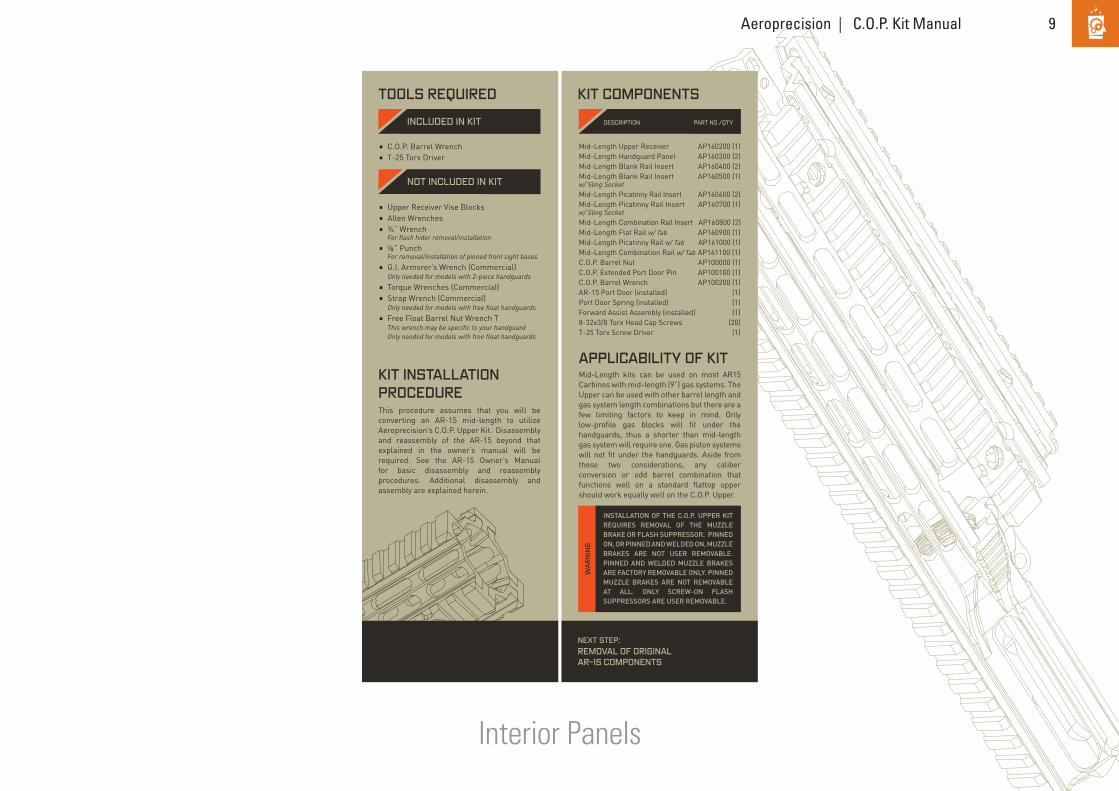
Mid-Length kits can be used on most AR15 Carbines with mid-length (9”) gas systems. The Upper can be used with other barrel length and gas system length combinations but there are a few limiting factors to keep in mind. Only low-profile gas blocks will fit under the handguards, thus a shorter than mid-length gas system will require one. Gas piston systems will not fit under the handguards. Aside from these two considerations, any caliber conversion or odd barrel combination that functions well on a standard flattop upper should work equally well on the C.O.P. Upper.
• •
This procedure assumes that you will be converting an AR-15 mid-length to utilize Aeroprecision’s C.O.P. Upper Kit. Disassembly and reassembly of the AR-15 beyond that explained in the owner’s manual will be required. See the AR-15 Owner’s Manual for basic disassembly and reassembly procedures. Additional disassembly and assembly are explained herein.
2338 HOLGATE STREETTACOMA, WASHINGTON 98402
253.272.8188
AEROPRECISIONUSA.COM
TOOLS REQUIRED
KIT INSTALLATION PROCEDURE
APPLICABILITY OF KIT
KIT COMPONENTS
!
!
REMOVAL OF ORIGINAL AR-15 COMPONENTS
PLACE the safety selector on “SAFE.”
REMOVE the flash hider using a ¾” wrench.
IF the firearm has two-piece handguards, remove them in accordance with the owner’s manual.
LOOK at the front sight base/gas block. If it is pinned onto the barrel, drive out the two pins with a 1/8” punch. If it is held to the barrel with screws, loosen the retaining screws. Then slide/tap the base and gas tube assembly forward until it comes free.
CLOSE the ejection port door. Clamp the upper receiver into a vise using the universal vise blocks. Be careful to use the minimum amount of clamping force needed to retain the upper receiver. If your carbine has a free float handguard, use a strap wrench to grasp the handguard lock ring at the front of the receiver. Loosen the ring by rotating it counterclockwise as viewed from the butt and pull forward on the handguard at the same time. Wiggling the handguard slightly as it loosens may help.
REMOVE the handguard lock ring, handguard, barrel nut, and barrel from the receiver. If your firearm had two piece handguards, use the G.I. Armorer’s wrench to remove the barrel nut. If it had a free float handguard, use the free float handguard barrel nut wrench.
REMOVE the magazine by pressing the magazine catch button and pulling the magazine down and out of the receiver. Remove the magazine and all sources of ammunition from the work area.
EXTRACT the cartridge (if any) from the chamber. To extract a cartridge pull the bolt carrier assembly fully to the rear. If there is a cartridge in the chamber, it should be extracted and ejected from the firearm.
LOOK into the chamber to assure that it does not contain a cartridge.REMOVE the upper receiver assembly
from the lower receiver assembly as directed in your owner’s manual. Then remove the bolt carrier assembly and charging handle from the upper receiver assembly.
ALWAYS ASSUME ALL FIREARMS ARE LOADED. ANYTIME YOU HANDLE A FIREARM, YOU SHOULD IMMEDIATELY INSPECT IT TO ASSURE THAT IT IS COMPLETELY UNLOADED.
THE MAGAZINE WILL FALL FREE WHEN THE MAGAZINE CATCH IS PRESSED. DON’T ALLOW THE MAGAZINE TO FALL ONTO A HARD SURFACE. DOING SO MAY DAMAGE THE MAGAZINE.
INSTALLATION OF THE C.O.P. UPPER KIT REQUIRES REMOVAL OF THE MUZZLE BRAKE OR FLASH SUPPRESSOR. PINNED ON, OR PINNED AND WELDED ON, MUZZLE BRAKES ARE NOT USER REMOVABLE. PINNED AND WELDED MUZZLE BRAKES ARE FACTORY REMOVABLE ONLY. PINNED MUZZLE BRAKES ARE NOT REMOVABLE AT ALL. ONLY SCREW-ON FLASH SUPPRESSORS ARE USER REMOVABLE.
THE STEPS IN UNLOADING YOUR FIREARM MUST BE FOLLOWED IN THE EXACT ORDER GIVEN. THE MAGAZINE MUST BE REMOVED BEFORE THE CHAMBER IS INSPECTED. IF YOU CLEAR THE CHAMBER BEFORE REMOVING THE MAGAZINE, YOU MAY REMOVE ONE CARTRIDGE FROM THE CHAMBER AND THEN, UPON CLOSING THE BOLT, CHAMBER ANOTHER CARTRIDGE FROM THE MAGAZINE. THE FIREARM WILL STILL BE LOADED. REMEMBER THAT A CARTRIDGE IN THE CHAMBER CAN STILL BE FIRED EVEN AFTER THE MAGAZINE IS REMOVED.
STEP FIVE
STEP SIX
STEP SEVEN
STEP EIGHT
STEP NINE
STEP ONE
STEP TWO
STEP FOUR
WA
RNIN
G
CAU
TION
WA
RNIN
G WA
RNIN
G
3
5
6
7
8
9
1
2
4
INSTALLATION OF THE C.O.P. UPPER KIT REQUIRES REMOVAL OF THE MUZZLE BRAKE OR FLASH SUPPRESSOR. PINNED ON, OR PINNED AND WELDED ON, MUZZLE BRAKES ARE NOT USER REMOVABLE. PINNED AND WELDED MUZZLE BRAKES ARE FACTORY REMOVABLE ONLY. PINNED MUZZLE BRAKES ARE NOT REMOVABLE AT ALL. ONLY SCREW-ON FLASH SUPPRESSORS ARE USER REMOVABLE.
WA
RN
ING
INCLUDED IN KITDESCRIPTION PART NO./QTY
NOT INCLUDED IN KIT
ASSEMBLY MANUAL
NEXT STEP:INSTALLATION OF C.O.P. UPPER KIT
STEP THREE
NEXT STEP:REMOVAL OF ORIGINAL AR-15 COMPONENTS
C.O.P. Barrel Wrench T-25 Torx Driver
Mid-Length Upper Receiver AP160200 (1)Mid-Length Handguard Panel AP160300 (2)Mid-Length Blank Rail Insert AP160400 (2)Mid-Length Blank Rail Insert AP160500 (1)w/ Sling Socket Mid-Length Picatinny Rail Insert AP160600 (2)Mid-Length Picatinny Rail Insert AP160700 (1)w/ Sling Socket Mid-Length Combination Rail Insert AP160800 (2) Mid-Length Flat Rail w/ Tab AP160900 (1)Mid-Length Picatinny Rail w/ Tab AP161000 (1)Mid-Length Combination Rail w/ Tab AP161100 (1)C.O.P. Barrel Nut AP100000 (1)C.O.P. Extended Port Door Pin AP100100 (1)C.O.P. Barrel Wrench AP100200 (1)AR-15 Port Door (installed) (1)Port Door Spring (installed) (1)Forward Assist Assembly (installed) (1)8-32x3/8 Torx Head Cap Screws (20)T-25 Torx Screw Driver (1)
MID-LENGTH
AR15 C.O.P. KIT
Upper Receiver Vise BlocksAllen Wrenches¾” Wrench For flash hider removal/installation ” Punch For removal/installation of pinned front sight basesG.I. Armorer’s Wrench (Commercial) Only needed for models with 2-piece handguardsTorque Wrenches (Commercial)Strap Wrench (Commercial) Only needed for models with free float handguardsFree Float Barrel Nut Wrench TThis wrench may be specific to your handguard Only needed for models with free float handguards
•
•
•
•
•
•
•
•
9Aeroprecision | C.O.P. Kit Manual
Interior Panels
Mid-Length kits can be used on most AR15 Carbines with mid-length (9”) gas systems. The Upper can be used with other barrel length and gas system length combinations but there are a few limiting factors to keep in mind. Only low-profile gas blocks will fit under the handguards, thus a shorter than mid-length gas system will require one. Gas piston systems will not fit under the handguards. Aside from these two considerations, any caliber conversion or odd barrel combination that functions well on a standard flattop upper should work equally well on the C.O.P. Upper.
• •
This procedure assumes that you will be converting an AR-15 mid-length to utilize Aeroprecision’s C.O.P. Upper Kit. Disassembly and reassembly of the AR-15 beyond that explained in the owner’s manual will be required. See the AR-15 Owner’s Manual for basic disassembly and reassembly procedures. Additional disassembly and assembly are explained herein.
2338 HOLGATE STREETTACOMA, WASHINGTON 98402
253.272.8188
AEROPRECISIONUSA.COM
TOOLS REQUIRED
KIT INSTALLATION PROCEDURE
APPLICABILITY OF KIT
KIT COMPONENTS
!
!
REMOVAL OF ORIGINAL AR-15 COMPONENTS
PLACE the safety selector on “SAFE.”
REMOVE the flash hider using a ¾” wrench.
IF the firearm has two-piece handguards, remove them in accordance with the owner’s manual.
LOOK at the front sight base/gas block. If it is pinned onto the barrel, drive out the two pins with a 1/8” punch. If it is held to the barrel with screws, loosen the retaining screws. Then slide/tap the base and gas tube assembly forward until it comes free.
CLOSE the ejection port door. Clamp the upper receiver into a vise using the universal vise blocks. Be careful to use the minimum amount of clamping force needed to retain the upper receiver. If your carbine has a free float handguard, use a strap wrench to grasp the handguard lock ring at the front of the receiver. Loosen the ring by rotating it counterclockwise as viewed from the butt and pull forward on the handguard at the same time. Wiggling the handguard slightly as it loosens may help.
REMOVE the handguard lock ring, handguard, barrel nut, and barrel from the receiver. If your firearm had two piece handguards, use the G.I. Armorer’s wrench to remove the barrel nut. If it had a free float handguard, use the free float handguard barrel nut wrench.
REMOVE the magazine by pressing the magazine catch button and pulling the magazine down and out of the receiver. Remove the magazine and all sources of ammunition from the work area.
EXTRACT the cartridge (if any) from the chamber. To extract a cartridge pull the bolt carrier assembly fully to the rear. If there is a cartridge in the chamber, it should be extracted and ejected from the firearm.
LOOK into the chamber to assure that it does not contain a cartridge.REMOVE the upper receiver assembly
from the lower receiver assembly as directed in your owner’s manual. Then remove the bolt carrier assembly and charging handle from the upper receiver assembly.
ALWAYS ASSUME ALL FIREARMS ARE LOADED. ANYTIME YOU HANDLE A FIREARM, YOU SHOULD IMMEDIATELY INSPECT IT TO ASSURE THAT IT IS COMPLETELY UNLOADED.
THE MAGAZINE WILL FALL FREE WHEN THE MAGAZINE CATCH IS PRESSED. DON’T ALLOW THE MAGAZINE TO FALL ONTO A HARD SURFACE. DOING SO MAY DAMAGE THE MAGAZINE.
INSTALLATION OF THE C.O.P. UPPER KIT REQUIRES REMOVAL OF THE MUZZLE BRAKE OR FLASH SUPPRESSOR. PINNED ON, OR PINNED AND WELDED ON, MUZZLE BRAKES ARE NOT USER REMOVABLE. PINNED AND WELDED MUZZLE BRAKES ARE FACTORY REMOVABLE ONLY. PINNED MUZZLE BRAKES ARE NOT REMOVABLE AT ALL. ONLY SCREW-ON FLASH SUPPRESSORS ARE USER REMOVABLE.
THE STEPS IN UNLOADING YOUR FIREARM MUST BE FOLLOWED IN THE EXACT ORDER GIVEN. THE MAGAZINE MUST BE REMOVED BEFORE THE CHAMBER IS INSPECTED. IF YOU CLEAR THE CHAMBER BEFORE REMOVING THE MAGAZINE, YOU MAY REMOVE ONE CARTRIDGE FROM THE CHAMBER AND THEN, UPON CLOSING THE BOLT, CHAMBER ANOTHER CARTRIDGE FROM THE MAGAZINE. THE FIREARM WILL STILL BE LOADED. REMEMBER THAT A CARTRIDGE IN THE CHAMBER CAN STILL BE FIRED EVEN AFTER THE MAGAZINE IS REMOVED.
STEP FIVE
STEP SIX
STEP SEVEN
STEP EIGHT
STEP NINE
STEP ONE
STEP TWO
STEP FOUR
WA
RNIN
G
CAU
TION
WA
RNIN
G WA
RNIN
G
3
5
6
7
8
9
1
2
4
INSTALLATION OF THE C.O.P. UPPER KIT REQUIRES REMOVAL OF THE MUZZLE BRAKE OR FLASH SUPPRESSOR. PINNED ON, OR PINNED AND WELDED ON, MUZZLE BRAKES ARE NOT USER REMOVABLE. PINNED AND WELDED MUZZLE BRAKES ARE FACTORY REMOVABLE ONLY. PINNED MUZZLE BRAKES ARE NOT REMOVABLE AT ALL. ONLY SCREW-ON FLASH SUPPRESSORS ARE USER REMOVABLE.
WA
RN
ING
INCLUDED IN KITDESCRIPTION PART NO./QTY
NOT INCLUDED IN KIT
ASSEMBLY MANUAL
NEXT STEP:INSTALLATION OF C.O.P. UPPER KIT
STEP THREE
NEXT STEP:REMOVAL OF ORIGINAL AR-15 COMPONENTS
C.O.P. Barrel Wrench T-25 Torx Driver
Mid-Length Upper Receiver AP160200 (1)Mid-Length Handguard Panel AP160300 (2)Mid-Length Blank Rail Insert AP160400 (2)Mid-Length Blank Rail Insert AP160500 (1)w/ Sling Socket Mid-Length Picatinny Rail Insert AP160600 (2)Mid-Length Picatinny Rail Insert AP160700 (1)w/ Sling Socket Mid-Length Combination Rail Insert AP160800 (2) Mid-Length Flat Rail w/ Tab AP160900 (1)Mid-Length Picatinny Rail w/ Tab AP161000 (1)Mid-Length Combination Rail w/ Tab AP161100 (1)C.O.P. Barrel Nut AP100000 (1)C.O.P. Extended Port Door Pin AP100100 (1)C.O.P. Barrel Wrench AP100200 (1)AR-15 Port Door (installed) (1)Port Door Spring (installed) (1)Forward Assist Assembly (installed) (1)8-32x3/8 Torx Head Cap Screws (20)T-25 Torx Screw Driver (1)
MID-LENGTH
AR15 C.O.P. KIT
Upper Receiver Vise BlocksAllen Wrenches¾” Wrench For flash hider removal/installation ” Punch For removal/installation of pinned front sight basesG.I. Armorer’s Wrench (Commercial) Only needed for models with 2-piece handguardsTorque Wrenches (Commercial)Strap Wrench (Commercial) Only needed for models with free float handguardsFree Float Barrel Nut Wrench TThis wrench may be specific to your handguard Only needed for models with free float handguards
•
•
•
•
•
•
•
•

10Aeroprecision | C.O.P. Kit Manual
Interior Page
Mid-Length kits can be used on most AR15 Carbines with mid-length (9”) gas systems. The Upper can be used with other barrel length and gas system length combinations but there are a few limiting factors to keep in mind. Only low-profile gas blocks will fit under the handguards, thus a shorter than mid-length gas system will require one. Gas piston systems will not fit under the handguards. Aside from these two considerations, any caliber conversion or odd barrel combination that functions well on a standard flattop upper should work equally well on the C.O.P. Upper.
• •
This procedure assumes that you will be converting an AR-15 mid-length to utilize Aeroprecision’s C.O.P. Upper Kit. Disassembly and reassembly of the AR-15 beyond that explained in the owner’s manual will be required. See the AR-15 Owner’s Manual for basic disassembly and reassembly procedures. Additional disassembly and assembly are explained herein.
2338 HOLGATE STREETTACOMA, WASHINGTON 98402
253.272.8188
AEROPRECISIONUSA.COM
TOOLS REQUIRED
KIT INSTALLATION PROCEDURE
APPLICABILITY OF KIT
KIT COMPONENTS
!
!
REMOVAL OF ORIGINAL AR-15 COMPONENTS
PLACE the safety selector on “SAFE.”
REMOVE the flash hider using a ¾” wrench.
IF the firearm has two-piece handguards, remove them in accordance with the owner’s manual.
LOOK at the front sight base/gas block. If it is pinned onto the barrel, drive out the two pins with a 1/8” punch. If it is held to the barrel with screws, loosen the retaining screws. Then slide/tap the base and gas tube assembly forward until it comes free.
CLOSE the ejection port door. Clamp the upper receiver into a vise using the universal vise blocks. Be careful to use the minimum amount of clamping force needed to retain the upper receiver. If your carbine has a free float handguard, use a strap wrench to grasp the handguard lock ring at the front of the receiver. Loosen the ring by rotating it counterclockwise as viewed from the butt and pull forward on the handguard at the same time. Wiggling the handguard slightly as it loosens may help.
REMOVE the handguard lock ring, handguard, barrel nut, and barrel from the receiver. If your firearm had two piece handguards, use the G.I. Armorer’s wrench to remove the barrel nut. If it had a free float handguard, use the free float handguard barrel nut wrench.
REMOVE the magazine by pressing the magazine catch button and pulling the magazine down and out of the receiver. Remove the magazine and all sources of ammunition from the work area.
EXTRACT the cartridge (if any) from the chamber. To extract a cartridge pull the bolt carrier assembly fully to the rear. If there is a cartridge in the chamber, it should be extracted and ejected from the firearm.
LOOK into the chamber to assure that it does not contain a cartridge. REMOVE the upper receiver assembly
from the lower receiver assembly as directed in your owner’s manual. Then remove the bolt carrier assembly and charging handle from the upper receiver assembly.
ALWAYS ASSUME ALL FIREARMS ARE LOADED. ANYTIME YOU HANDLE A FIREARM, YOU SHOULD IMMEDIATELY INSPECT IT TO ASSURE THAT IT IS COMPLETELY UNLOADED.
THE MAGAZINE WILL FALL FREE WHEN THE MAGAZINE CATCH IS PRESSED. DON’T ALLOW THE MAGAZINE TO FALL ONTO A HARD SURFACE. DOING SO MAY DAMAGE THE MAGAZINE.
INSTALLATION OF THE C.O.P. UPPER KIT REQUIRES REMOVAL OF THE MUZZLE BRAKE OR FLASH SUPPRESSOR. PINNED ON, OR PINNED AND WELDED ON, MUZZLE BRAKES ARE NOT USER REMOVABLE. PINNED AND WELDED MUZZLE BRAKES ARE FACTORY REMOVABLE ONLY. PINNED MUZZLE BRAKES ARE NOT REMOVABLE AT ALL. ONLY SCREW-ON FLASH SUPPRESSORS ARE USER REMOVABLE.
THE STEPS IN UNLOADING YOUR FIREARM MUST BE FOLLOWED IN THE EXACT ORDER GIVEN. THE MAGAZINE MUST BE REMOVED BEFORE THE CHAMBER IS INSPECTED. IF YOU CLEAR THE CHAMBER BEFORE REMOVING THE MAGAZINE, YOU MAY REMOVE ONE CARTRIDGE FROM THE CHAMBER AND THEN, UPON CLOSING THE BOLT, CHAMBER ANOTHER CARTRIDGE FROM THE MAGAZINE. THE FIREARM WILL STILL BE LOADED. REMEMBER THAT A CARTRIDGE IN THE CHAMBER CAN STILL BE FIRED EVEN AFTER THE MAGAZINE IS REMOVED.
STEP FIVE
STEP SIX
STEP SEVEN
STEP EIGHT
STEP NINE
STEP ONE
STEP TWO
STEP FOUR
WA
RNIN
G
CAU
TIO
N
WA
RNIN
G WA
RNIN
G
3
5
6
7
8
9
1
2
4
INSTALLATION OF THE C.O.P. UPPER KIT REQUIRES REMOVAL OF THE MUZZLE BRAKE OR FLASH SUPPRESSOR. PINNED ON, OR PINNED AND WELDED ON, MUZZLE BRAKES ARE NOT USER REMOVABLE. PINNED AND WELDED MUZZLE BRAKES ARE FACTORY REMOVABLE ONLY. PINNED MUZZLE BRAKES ARE NOT REMOVABLE AT ALL. ONLY SCREW-ON FLASH SUPPRESSORS ARE USER REMOVABLE.
WA
RN
ING
INCLUDED IN KIT DESCRIPTIONPART NO./QTY
NOT INCLUDED IN KIT
ASSEMBLY MANUAL
NEXT STEP:INSTALLATION OF C.O.P. UPPER KIT
STEP THREE
NEXT STEP:REMOVAL OF ORIGINAL AR-15 COMPONENTS
C.O.P. Barrel Wrench T-25 Torx Driver
Mid-Length Upper Receiver AP160200 (1)Mid-Length Handguard Panel AP160300 (2)Mid-Length Blank Rail Insert AP160400 (2)Mid-Length Blank Rail Insert AP160500 (1)w/ Sling Socket Mid-Length Picatinny Rail Insert AP160600 (2)Mid-Length Picatinny Rail Insert AP160700 (1)w/ Sling Socket Mid-Length Combination Rail Insert AP160800 (2) Mid-Length Flat Rail w/ Tab AP160900 (1)Mid-Length Picatinny Rail w/ Tab AP161000 (1)Mid-Length Combination Rail w/ Tab AP161100 (1)C.O.P. Barrel Nut AP100000 (1)C.O.P. Extended Port Door Pin AP100100 (1)C.O.P. Barrel Wrench AP100200 (1)AR-15 Port Door (installed) (1)Port Door Spring (installed) (1)Forward Assist Assembly (installed) (1)8-32x3/8 Torx Head Cap Screws (20)T-25 Torx Screw Driver (1)
MID-LENGTH
AR15 C.O.P. KIT
Upper Receiver Vise BlocksAllen Wrenches¾” Wrench For flash hider removal/installation ” Punch For removal/installation of pinned front sight basesG.I. Armorer’s Wrench (Commercial) Only needed for models with 2-piece handguardsTorque Wrenches (Commercial)Strap Wrench (Commercial) Only needed for models with free float handguardsFree Float Barrel Nut Wrench TThis wrench may be specific to your handguard Only needed for models with free float handguards
•
•
•
•
•
•
•
•

11Aeroprecision | C.O.P. Kit Manual
Interior Page
INSTALLATION OF AR15 COP KIT
STEP ONE: KIT PREPARATION
STEP TWO: KIT CONSTRUCTION
GREASE the threads in the C.O.P. upper receiver lightly with heavy duty grease. Install the barrel nut onto the barrel. Install the barrel and barrel nut to the upper receiver. Torque the barrel nut onto the upper receiver to 55 ft-lb.
NOTE: THE BARREL WRENCH MUST BE FULLY SEATED ON THE BARREL NUT LUGS, FAILURE TO DO SO CAN, IN RARE CASES, RESULT IN WRENCH BREAKAGE! THE BARREL NUT DOES NOT NEED TO BE INDEXED TO CLEAR THE GAS TUBE.
INSTALL the front sight base/gas block and gas tube assembly onto the barrel by gently sliding/tapping it into place. The front sight base/gas block must be vertical and aligned with the centerline of the upper receiver. Lock it in place using the screws torqued to 65 in-lbs, or replace the two pins.
IF your firearm originally had two-piece handguards, dispose of the original handguard cap and install the gas block spacer in its place.
REINSTALL the flash hider washers and flash suppressor. Using a ¾” wrench, torque the flash suppressor until its flats are vertical.
ALWAYS TEST FIRE YOUR WEAPON BEFORE USING IN AN OPERATIONAL ENVIRONMENT.
STEP ONE STEP THREE
STEP TWO STEP FOUR
WA
RNIN
G
1 3
2 4
Your kit comes with an assortment of rail inserts. The blank rail inserts are intended for situations where a comfortable grip and clean lines are desired. The picatinny rail inserts are intended for accessory mounting. The combination rails are a compromise between the two. A sling swivel socket equipped version of each style is also included for sling use; these inserts may be used on the left or right side and with the socket toward the front or rear of the handguard.
To install the lower half of the handguard, select the rail insert for the bottom of the handguard and hold the insert and handguard panels arranged so that the edge of each handguard panel with the three threaded holes is toward the rail insert. Install and lightly tighten the screws.
SELECT the rail inserts for the remaining two sides of the handguard. Install and lightly tighten the remaining screws. Then torque all screws in an alternating pattern to 25 in-lbs.
CLEAN, LUBE AND FUNCTION CHECK your mid-length in accordance with the Owner’s Manual. Test fire your mid-length to assure that you have reassembled it correctly.
STEP ONE STEP TWO
STEP THREE
1 2
3
DO NOT TORQUE THE SCREWS ABOVE 40 IN LBS. DOING SO MAY RESULT IN STRIPPING THE SCREW HOLES. CA
UTI
ON
AEROPRECISIONUSA.COM
FLASH SUPPRESSORBARREL
BARREL ASSEMBLY DIAGRAM
HANDGUARD ASSEMBLY DIAGRAM
BARREL NUT
SEE “KIT COMPONENTS” FOR ALL PARTS INCLUDED.
HANDGUARD PANELS
RAIL INSERTS

Thank You!
![PARTS GUIDE - 6L Distribuidora de insumos para … · PARTS GUIDE SHARP CORPORATION CODE:00ZARM206/025 CONTENTS 1 Exteriors 2 Operation panel section 3 Side door unit ... [AR-M161/AR-M162/AR-M162E/AR-M165]07/10](https://img.pdfslide.net/doc/110x75/5b7a45347f8b9a22238bd0a1/parts-guide-6l-distribuidora-de-insumos-para-parts-guide-sharp-corporation.jpg)


![MODEL AR-FN6 - Diagramas dediagramas.diagramasde.com/otros/AR-FN6-SM.pdf · for AR-FN4 & AR-FN6 !" # $ AR-FN6 UNPACKING AND INSTALLATION 4-1 [4] ... indicators on the operation panel](https://img.pdfslide.net/doc/110x75/5b4f23ca7f8b9a256e8ba86c/model-ar-fn6-diagramas-for-ar-fn4-ar-fn6-ar-fn6-unpacking-and-installation.jpg)


![CYNGOR SIR YNYS MȎNdemocratiaeth.ynysmon.gov.uk/documents/s500002602/Panel...dinesydd] 3.2 Edrych ar effeithlonrwydd ac effeithiolrwydd unrhyw newid arfaethedig – yn ariannol ac](https://img.pdfslide.net/doc/110x75/60e41b946fcfea32526881f6/cyngor-sir-ynys-m-dinesydd-32-edrych-ar-effeithlonrwydd-ac-effeithiolrwydd.jpg)