Embed Size (px)
Citation preview
U S E R G U I D EAEROS 9040
Software version 4.21
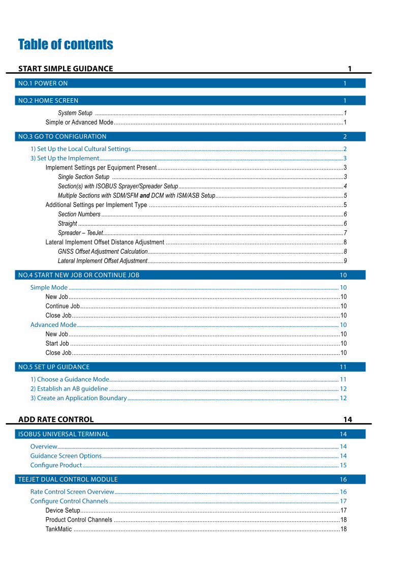
Table of contentsSTART SIMPLE GUIDANCE 1
NO.1 POWER ON 1
NO.2 HOME SCREEN 1
System Setup .................................................................................................................................................................1Simple or Advanced Mode .........................................................................................................................................1
NO.3 GO TO CONFIGURATION 2
1) Set Up the Local Cultural Settings .......................................................................................................................................................23) Set Up the Implement ..............................................................................................................................................................................3
Implement Settings per Equipment Present ...............................................................................................................3Single Section Setup ......................................................................................................................................................3Section(s) with ISOBUS Sprayer/Spreader Setup ...........................................................................................................4Multiple Sections with SDM/SFM and DCM with ISM/ASB Setup ...................................................................................5
Additional Settings per Implement Type ....................................................................................................................5Section Numbers .............................................................................................................................................................6Straight ............................................................................................................................................................................6Spreader – TeeJet ............................................................................................................................................................7
Lateral Implement Offset Distance Adjustment ..........................................................................................................8GNSS Offset Adjustment Calculation ...............................................................................................................................8Lateral Implement Offset Adjustment ...............................................................................................................................9
NO.4 START NEW JOB OR CONTINUE JOB 10
Simple Mode ................................................................................................................................................................................................. 10New Job ..................................................................................................................................................................10Continue Job ...........................................................................................................................................................10Close Job ................................................................................................................................................................10
Advanced Mode ........................................................................................................................................................................................... 10New Job ..................................................................................................................................................................10Start Job .................................................................................................................................................................10Close Job ................................................................................................................................................................10
NO.5 SET UP GUIDANCE 11
1) Choose a Guidance Mode.................................................................................................................................................................... 112) Establish an AB guideline .................................................................................................................................................................... 123) Create an Application Boundary ....................................................................................................................................................... 12
ADD RATE CONTROL 14
ISOBUS UNIVERSAL TERMINAL 14
Overview ......................................................................................................................................................................................................... 14Guidance Screen Options ......................................................................................................................................................................... 14Configure Product ....................................................................................................................................................................................... 15
TEEJET DUAL CONTROL MODULE 16
Rate Control Screen Overview ................................................................................................................................................................ 16Configure Control Channels .................................................................................................................................................................... 17
Device Setup ...........................................................................................................................................................17Product Control Channels .......................................................................................................................................18TankMatic ...............................................................................................................................................................18
iii98-01504-EN R1
Aeros 9040 Field ComputerConfigure Product ....................................................................................................................................................................................... 19
APPLICATION MAPPING 20
Duplicating and Transferring Maps ..........................................................................................................................20Coverage Map ............................................................................................................................................................................................... 20Prescription Map .......................................................................................................................................................................................... 20Application Map ........................................................................................................................................................................................... 21Target Rate Map ........................................................................................................................................................................................... 21
Target Rates ...........................................................................................................................................................21
INFORMATION ON GUIDANCE MODES 22Vehicle View ................................................................................................................................................................................................... 22Field View ........................................................................................................................................................................................................ 23RealView Guidance ..................................................................................................................................................................................... 24
GUIDANCE MODES 25
GUIDANCE SCREEN ICONS 26
GUIDANCE BAR 28
STATUS BAR 29
GUIDANCE FEATURES DETAILS 30A+ Nudge Feature ....................................................................................................................................................................................... 30Azimuth Degree ........................................................................................................................................................................................... 30Return to Point.............................................................................................................................................................................................. 31
Marking a Return Point ............................................................................................................................................31Delete the Return Point ...........................................................................................................................................31Guidance to a Return Point .....................................................................................................................................31
Next Guideline Feature .............................................................................................................................................................................. 32
BOOMPILOT 32
No Section Control Module ..................................................................................................................................................................... 33Console Only ..........................................................................................................................................................33With Optional Work On/Off Switch ...........................................................................................................................33
Using the Console..........................................................................................................................................................33ISOBUS Sprayer ............................................................................................................................................................................................. 33
Console and ECU Only ...........................................................................................................................................33With Switchbox .......................................................................................................................................................34With an ISOBUS Implement Status Module (ISO ISM) .............................................................................................34
ISOBUS Spreader .......................................................................................................................................................................................... 34Console Only ..........................................................................................................................................................34With Optional Spreader On/Off Switch .....................................................................................................................35
With TeeJet Section Control Module and Switchbox or ISM ........................................................................................................ 35With TeeJet Section Control Module .................................................................................................................................................... 35
ADDITIONAL IMPLEMENT OPTIONS 36
NOZZLE SELECTION 36
Preset .....................................................................................................................................................................36Current Nozzle ........................................................................................................................................................37
DROPLET SIZE MONITOR 37
iv www.teejet.com
Aeros 9040 Field ComputerSetup ................................................................................................................................................................................................................ 37
Enable/Disable DSM ...............................................................................................................................................37Nozzle Selection / Current Nozzle ...........................................................................................................................37Input/Output Module Pressure Sensor .....................................................................................................................37
Operation ....................................................................................................................................................................................................... 38Status Bar ...............................................................................................................................................................38
Droplet Size Chart..........................................................................................................................................................38Guidance Bar ..........................................................................................................................................................38
REVERSE SENSE MODULE 38
Reverse on Guidance Screens ................................................................................................................................39
GROUND SPEED OVERRIDE 39
BOOMPILOT 40
BoomPilot Start Mode .............................................................................................................................................40BoomPilot Icon ........................................................................................................................................................40
NOZZLE FLOW MONITOR 41
DATA MANAGEMENT 41Job Data .......................................................................................................................................................................................................... 42Machine Settings ......................................................................................................................................................................................... 42
SYSTEM CONFIGURATIONS 43
Safety informationTeeJet Technologies is not responsible for damage or physical harm caused by failure to adhere to the following safety requirements.
As the operator of the vehicle, you are responsible for its safe operation.
The Aeros 9040 in combination with any assisted/auto steering device is not designed to replace the vehicle’s operator.
Do not leave a vehicle while the Aeros 9040 is engaged.
Be sure that the area around the vehicle is clear of people and obstacles before and during engagement.
The Aeros 9040 is designed to support and improve efficiency while working in the field. The driver has full responsibility for the quality and work related results.
Disengage or remove any assisted/auto steering device before operating on public roads.
198-01504-EN R1
Aeros 9040 Field ComputerSTART SIMPLE GUIDANCE
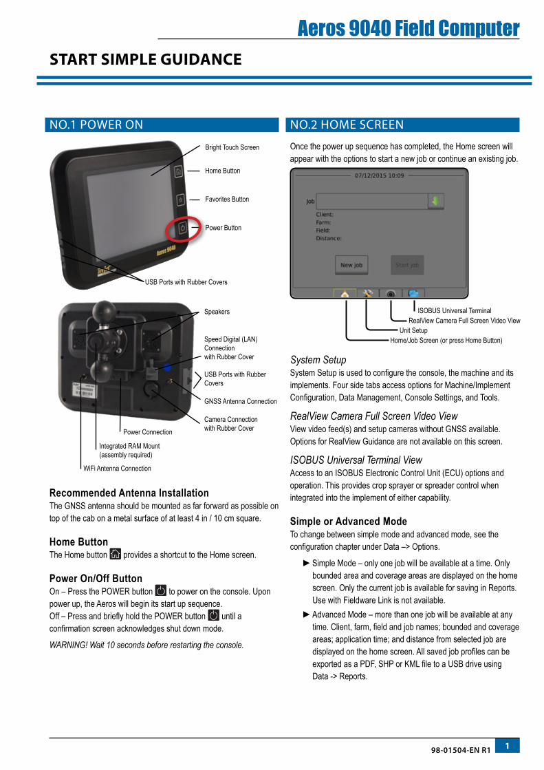
NO.1 POWER ON
Integrated RAM Mount(assembly required)
Speed Digital (LAN) Connection with Rubber Cover
Camera Connection with Rubber CoverPower Connection
Speakers
GNSS Antenna Connection
WiFi Antenna Connection
USB Ports with Rubber Covers
USB Ports with Rubber Covers
Bright Touch Screen
Power Button
Favorites Button
Home Button
Recommended Antenna InstallationThe GNSS antenna should be mounted as far forward as possible on top of the cab on a metal surface of at least 4 in / 10 cm square.
Home ButtonThe Home button provides a shortcut to the Home screen.
Power On/Off ButtonOn – Press the POWER button to power on the console. Upon power up, the Aeros will begin its start up sequence.Off – Press and briefly hold the POWER button until a confirmation screen acknowledges shut down mode.
WARNING! Wait 10 seconds before restarting the console.
NO.2 HOME SCREEN
Once the power up sequence has completed, the Home screen will appear with the options to start a new job or continue an existing job.
Home/Job Screen (or press Home Button)Unit Setup
RealView Camera Full Screen Video ViewISOBUS Universal Terminal
System Setup System Setup is used to configure the console, the machine and its implements. Four side tabs access options for Machine/Implement Configuration, Data Management, Console Settings, and Tools.
RealView Camera Full Screen Video ViewView video feed(s) and setup cameras without GNSS available. Options for RealView Guidance are not available on this screen.
ISOBUS Universal Terminal ViewAccess to an ISOBUS Electronic Control Unit (ECU) options and operation. This provides crop sprayer or spreader control when integrated into the implement of either capability.
Simple or Advanced ModeTo change between simple mode and advanced mode, see the configuration chapter under Data –> Options.
►Simple Mode – only one job will be available at a time. Only bounded area and coverage areas are displayed on the home screen. Only the current job is available for saving in Reports. Use with Fieldware Link is not available.
►Advanced Mode – more than one job will be available at any time. Client, farm, field and job names; bounded and coverage areas; application time; and distance from selected job are displayed on the home screen. All saved job profiles can be exported as a PDF, SHP or KML file to a USB drive using Data -> Reports.
2 www.teejet.com
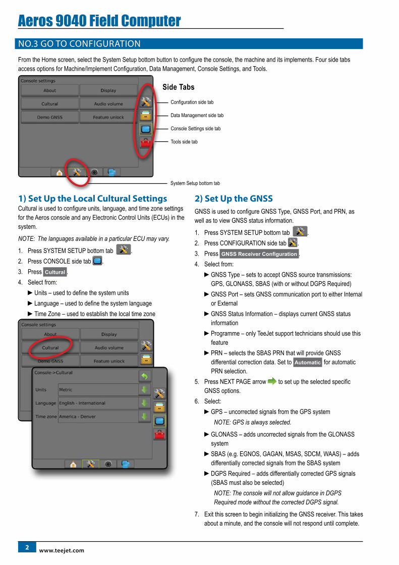
Aeros 9040 Field ComputerNO.3 GO TO CONFIGURATION
From the Home screen, select the System Setup bottom button to configure the console, the machine and its implements. Four side tabs access options for Machine/Implement Configuration, Data Management, Console Settings, and Tools.
Configuration side tab
Data Management side tab
Console Settings side tab
Tools side tab
System Setup bottom tab
Side Tabs
1) Set Up the Local Cultural SettingsCultural is used to configure units, language, and time zone settings for the Aeros console and any Electronic Control Units (ECUs) in the system.
NOTE: The languages available in a particular ECU may vary.
1. Press SYSTEM SETUP bottom tab .2. Press CONSOLE side tab .3. Press Cultural .4. Select from:
►Units – used to define the system units►Language – used to define the system language►Time Zone – used to establish the local time zone
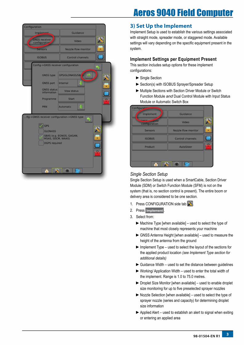
2) Set Up the GNSSGNSS is used to configure GNSS Type, GNSS Port, and PRN, as well as to view GNSS status information.
1. Press SYSTEM SETUP bottom tab .2. Press CONFIGURATION side tab .3. Press GNSS Receiver Configuration .4. Select from:
►GNSS Type – sets to accept GNSS source transmissions: GPS, GLONASS, SBAS (with or without DGPS Required)
►GNSS Port – sets GNSS communication port to either Internal or External
►GNSS Status Information – displays current GNSS status information
►Programme – only TeeJet support technicians should use this feature
►PRN – selects the SBAS PRN that will provide GNSS differential correction data. Set to Automatic for automatic PRN selection.
5. Press NEXT PAGE arrow to set up the selected specific GNSS options.
6. Select:►GPS – uncorrected signals from the GPS system
NOTE: GPS is always selected.
►GLONASS – adds uncorrected signals from the GLONASS system
►SBAS (e.g. EGNOS, GAGAN, MSAS, SDCM, WAAS) – adds differentially corrected signals from the SBAS system
►DGPS Required – adds differentially corrected GPS signals (SBAS must also be selected)
NOTE: The console will not allow guidance in DGPS Required mode without the corrected DGPS signal.
7. Exit this screen to begin initializing the GNSS receiver. This takes about a minute, and the console will not respond until complete.
398-01504-EN R1
Aeros 9040 Field Computer3) Set Up the ImplementImplement Setup is used to establish the various settings associated with straight mode, spreader mode, or staggered mode. Available settings will vary depending on the specific equipment present in the system.
Implement Settings per Equipment PresentThis section includes setup options for these implement configurations:
►Single Section►Section(s) with ISOBUS Sprayer/Spreader Setup►Multiple Sections with Section Driver Module or Switch
Function Module and Dual Control Module with Input Status Module or Automatic Switch Box
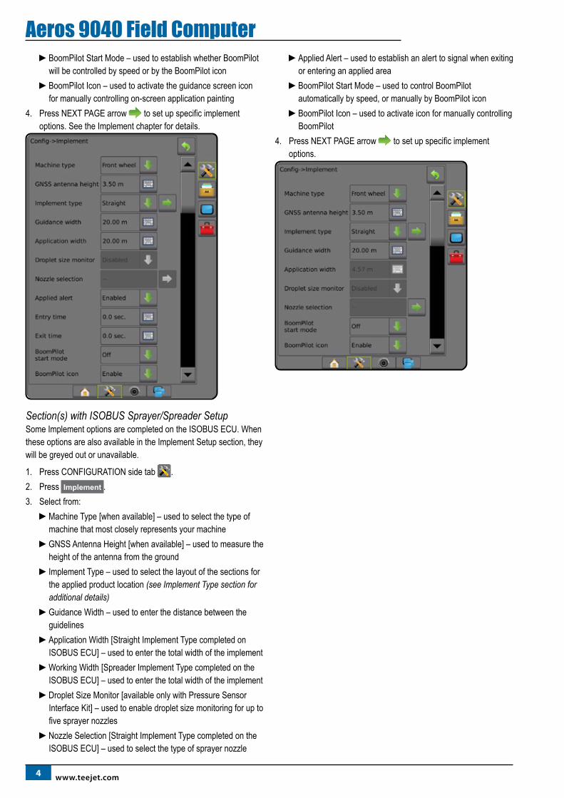
Single Section Setup Single Section Setup is used when a SmartCable, Section Driver Module (SDM) or Switch Function Module (SFM) is not on the system (that is, no section control is present). The entire boom or delivery area is considered to be one section.
1. Press CONFIGURATION side tab .2. Press Implement .3. Select from:
►Machine Type [when available] – used to select the type of machine that most closely represents your machine
►GNSS Antenna Height [when available] – used to measure the height of the antenna from the ground
►Implement Type – used to select the layout of the sections for the applied product location (see Implement Type section for additional details)
►Guidance Width – used to set the distance between guidelines►Working/ Application Width – used to enter the total width of
the implement. Range is 1.0 to 75.0 metres.►Droplet Size Monitor [when available] – used to enable droplet
size monitoring for up to five preselected sprayer nozzles►Nozzle Selection [when available] – used to select the type of
sprayer nozzle (series and capacity) for determining droplet size information
►Applied Alert – used to establish an alert to signal when exiting or entering an applied area
4 www.teejet.com
Aeros 9040 Field Computer►BoomPilot Start Mode – used to establish whether BoomPilot
will be controlled by speed or by the BoomPilot icon►BoomPilot Icon – used to activate the guidance screen icon
for manually controlling on-screen application painting4. Press NEXT PAGE arrow to set up specific implement
options. See the Implement chapter for details.
Section(s) with ISOBUS Sprayer/Spreader SetupSome Implement options are completed on the ISOBUS ECU. When these options are also available in the Implement Setup section, they will be greyed out or unavailable.
1. Press CONFIGURATION side tab .2. Press Implement .3. Select from:
►Machine Type [when available] – used to select the type of machine that most closely represents your machine
►GNSS Antenna Height [when available] – used to measure the height of the antenna from the ground
►Implement Type – used to select the layout of the sections for the applied product location (see Implement Type section for additional details)
►Guidance Width – used to enter the distance between the guidelines
►Application Width [Straight Implement Type completed on ISOBUS ECU] – used to enter the total width of the implement
►Working Width [Spreader Implement Type completed on the ISOBUS ECU] – used to enter the total width of the implement
►Droplet Size Monitor [available only with Pressure Sensor Interface Kit] – used to enable droplet size monitoring for up to five sprayer nozzles
►Nozzle Selection [Straight Implement Type completed on the ISOBUS ECU] – used to select the type of sprayer nozzle
►Applied Alert – used to establish an alert to signal when exiting or entering an applied area
►BoomPilot Start Mode – used to control BoomPilot automatically by speed, or manually by BoomPilot icon
►BoomPilot Icon – used to activate icon for manually controlling BoomPilot
4. Press NEXT PAGE arrow to set up specific implement options.
598-01504-EN R1
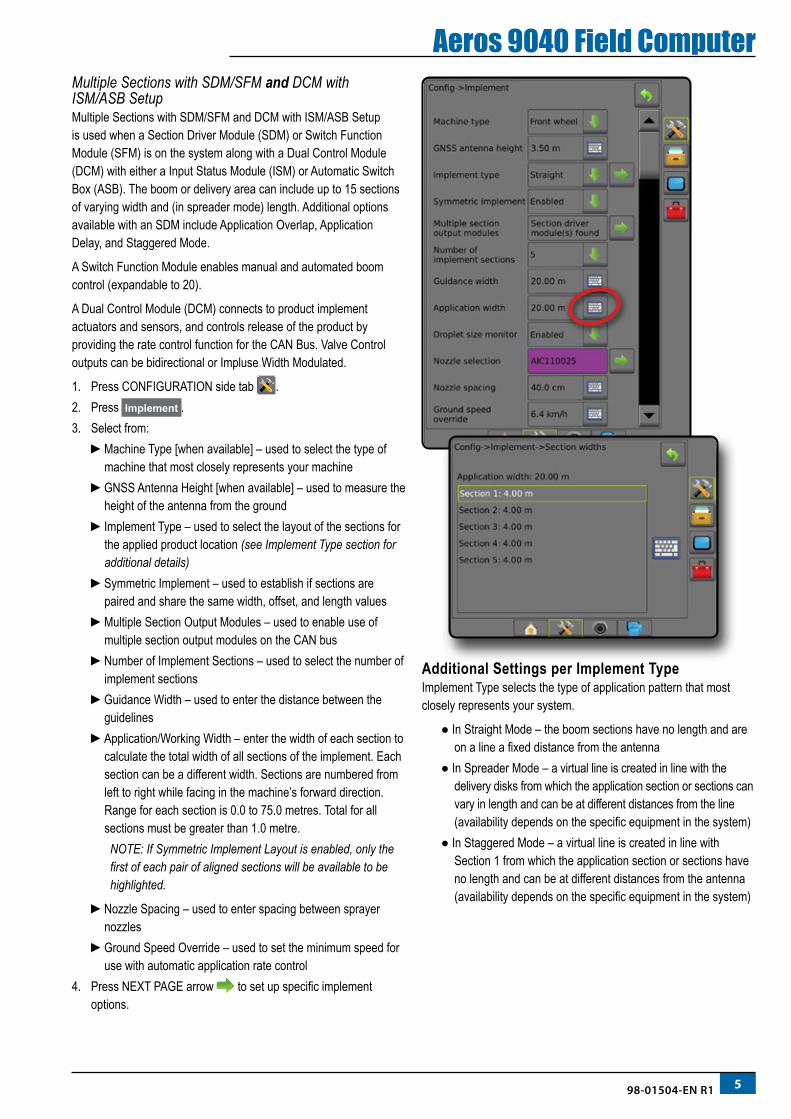
Aeros 9040 Field ComputerMultiple Sections with SDM/SFM and DCM with ISM/ASB SetupMultiple Sections with SDM/SFM and DCM with ISM/ASB Setup is used when a Section Driver Module (SDM) or Switch Function Module (SFM) is on the system along with a Dual Control Module (DCM) with either a Input Status Module (ISM) or Automatic Switch Box (ASB). The boom or delivery area can include up to 15 sections of varying width and (in spreader mode) length. Additional options available with an SDM include Application Overlap, Application Delay, and Staggered Mode.
A Switch Function Module enables manual and automated boom control (expandable to 20).
A Dual Control Module (DCM) connects to product implement actuators and sensors, and controls release of the product by providing the rate control function for the CAN Bus. Valve Control outputs can be bidirectional or Impluse Width Modulated.
1. Press CONFIGURATION side tab .2. Press Implement .3. Select from:
►Machine Type [when available] – used to select the type of machine that most closely represents your machine
►GNSS Antenna Height [when available] – used to measure the height of the antenna from the ground
►Implement Type – used to select the layout of the sections for the applied product location (see Implement Type section for additional details)
►Symmetric Implement – used to establish if sections are paired and share the same width, offset, and length values
►Multiple Section Output Modules – used to enable use of multiple section output modules on the CAN bus
►Number of Implement Sections – used to select the number of implement sections
►Guidance Width – used to enter the distance between the guidelines
►Application/Working Width – enter the width of each section to calculate the total width of all sections of the implement. Each section can be a different width. Sections are numbered from left to right while facing in the machine’s forward direction. Range for each section is 0.0 to 75.0 metres. Total for all sections must be greater than 1.0 metre.
NOTE: If Symmetric Implement Layout is enabled, only the first of each pair of aligned sections will be available to be highlighted.
►Nozzle Spacing – used to enter spacing between sprayer nozzles
►Ground Speed Override – used to set the minimum speed for use with automatic application rate control
4. Press NEXT PAGE arrow to set up specific implement options.
Additional Settings per Implement Type Implement Type selects the type of application pattern that most closely represents your system.
● In Straight Mode – the boom sections have no length and are on a line a fixed distance from the antenna
● In Spreader Mode – a virtual line is created in line with the delivery disks from which the application section or sections can vary in length and can be at different distances from the line (availability depends on the specific equipment in the system)
● In Staggered Mode – a virtual line is created in line with Section 1 from which the application section or sections have no length and can be at different distances from the antenna (availability depends on the specific equipment in the system)
6 www.teejet.com
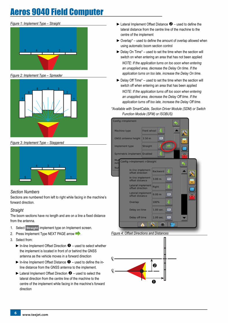
Aeros 9040 Field ComputerFigure 1: Implement Type – Straight
5 4 3 2 1
Figure 2: Implement Type – Spreader
56
7
4 32
1
Figure 3: Implement Type – Staggered
5
4 3 2
1
Section NumbersSections are numbered from left to right while facing in the machine’s forward direction.
StraightThe boom sections have no length and are on a line a fixed distance from the antenna.
1. Select Straight implement type on Implement screen.2. Press Implement Type NEXT PAGE arrow .3. Select from:
►In-line Implement Offset Direction – used to select whether the implement is located in front of or behind the GNSS antenna as the vehicle moves in a forward direction
►In-line Implement Offset Distance – used to define the in-line distance from the GNSS antenna to the implement.
►Lateral Implement Offset Direction – used to select the lateral direction from the centre line of the machine to the centre of the implement while facing in the machine’s forward direction
►Lateral Implement Offset Distance – used to define the lateral distance from the centre line of the machine to the centre of the implement
►Overlap* – used to define the amount of overlap allowed when using automatic boom section control
►Delay On Time* – used to set the time when the section will switch on when entering an area that has not been applied
NOTE: If the application turns on too soon when entering an unapplied area, decrease the Delay On time. If the application turns on too late, increase the Delay On time.
►Delay Off Time* – used to set the time when the section will switch off when entering an area that has been applied
NOTE: If the application turns off too soon when entering an unapplied area, decrease the Delay Off time. If the application turns off too late, increase the Delay Off time.
*Available with SmartCable, Section Driver Module (SDM) or Switch Function Module (SFM) or ISOBUS)
Figure 4: Offset Directions and Distances
798-01504-EN R1
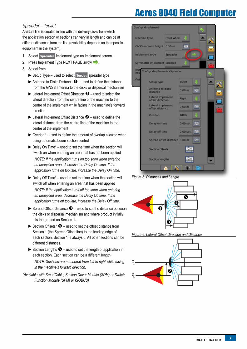
Aeros 9040 Field ComputerSpreader – TeeJetA virtual line is created in line with the delivery disks from which the application section or sections can vary in length and can be at different distances from the line (availability depends on the specific equipment in the system).
1. Select Spreader implement type on Implement screen.2. Press Implement Type NEXT PAGE arrow .3. Select from:
►Setup Type – used to select TeeJet spreader type ►Antenna to Disks Distance – used to define the distance
from the GNSS antenna to the disks or dispersal mechanism►Lateral Implement Offset Direction – used to select the
lateral direction from the centre line of the machine to the centre of the implement while facing in the machine’s forward direction
►Lateral Implement Offset Distance – used to define the lateral distance from the centre line of the machine to the centre of the implement
►Overlap* – used to define the amount of overlap allowed when using automatic boom section control
►Delay On Time* – used to set the time when the section will switch on when entering an area that has not been applied
NOTE: If the application turns on too soon when entering an unapplied area, decrease the Delay On time. If the application turns on too late, increase the Delay On time.
►Delay Off Time* – used to set the time when the section will switch off when entering an area that has been applied
NOTE: If the application turns off too soon when entering an unapplied area, decrease the Delay Off time. If the application turns off too late, increase the Delay Off time.
►Spread Offset Distance – used to set the distance between the disks or dispersal mechanism and where product initially hits the ground on Section 1.
►Section Offsets* – used to set the offset distance from Section 1 (the Spread Offset line) to the leading edge of each section. Section 1 is always 0. All other sections can be different distances.
►Section Lengths – used to set the length of application in each section. Each section can be a different length.
NOTE: Sections are numbered from left to right while facing in the machine’s forward direction.
*Available with SmartCable, Section Driver Module (SDM) or Switch Function Module (SFM) or ISOBUS)
Figure 5: Distances and Length
Figure 6: Lateral Offset Direction and Distance
8 www.teejet.com
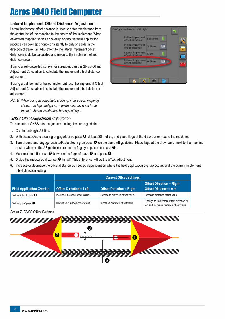
Aeros 9040 Field ComputerLateral Implement Offset Distance AdjustmentLateral implement offset distance is used to enter the distance from the centre line of the machine to the centre of the implement. When on-screen mapping shows no overlap or gap, yet field application produces an overlap or gap consistently to only one side in the direction of travel, an adjustment to the lateral implement offset distance should be calculated and made to the implement offset distance value.
If using a self-propelled sprayer or spreader, use the GNSS Offset Adjustment Calculation to calculate the implement offset distance adjustment.
If using a pull behind or trailed implement, use the Implement Offset Adjustment Calculation to calculate the implement offset distance adjustment.
NOTE: While using assisted/auto steering, if on-screen mapping shows overlaps and gaps, adjustments may need to be made to the assisted/auto steering settings.
GNSS Offset Adjustment CalculationTo calculate a GNSS offset adjustment using the same guideline:
1. Create a straight AB line.2. With assisted/auto steering engaged, drive pass at least 30 metres, and place flags at the draw bar or next to the machine.3. Turn around and engage assisted/auto steering on pass on the same AB guideline. Place flags at the draw bar or next to the machine,
or stop while on the AB guideline next to the flags you placed on pass .4. Measure the difference between the flags of pass and pass . 5. Divide the measured distance in half. This difference will be the offset adjustment.6. Increase or decrease the offset distance as needed dependent on where the field application overlap occurs and the current implement
offset direction setting.
Field Application Overlap
Current Offset Settings
Offset Direction = Left Offset Direction = RightOffset Direction = Right Offset Distance = 0 m
To the right of pass Increase distance offset value Decrease distance offset value Increase distance offset value
To the left of pass Decrease distance offset value Increase distance offset value Change to implement offset direction to left and increase distance offset value
Figure 7: GNSS Offset Distance
998-01504-EN R1
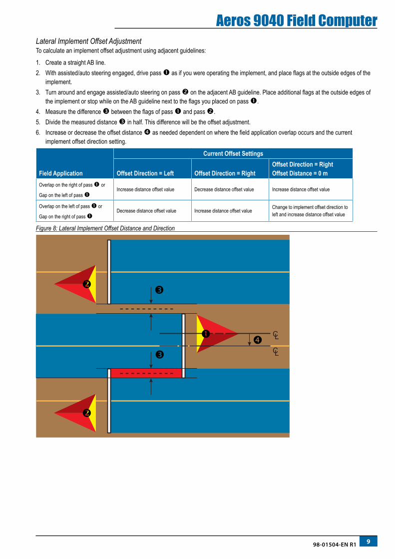
Aeros 9040 Field ComputerLateral Implement Offset AdjustmentTo calculate an implement offset adjustment using adjacent guidelines:
1. Create a straight AB line.2. With assisted/auto steering engaged, drive pass as if you were operating the implement, and place flags at the outside edges of the
implement.3. Turn around and engage assisted/auto steering on pass on the adjacent AB guideline. Place additional flags at the outside edges of
the implement or stop while on the AB guideline next to the flags you placed on pass .4. Measure the difference between the flags of pass and pass .5. Divide the measured distance in half. This difference will be the offset adjustment.6. Increase or decrease the offset distance as needed dependent on where the field application overlap occurs and the current
implement offset direction setting.
Field Application
Current Offset Settings
Offset Direction = Left Offset Direction = RightOffset Direction = Right Offset Distance = 0 m
Overlap on the right of pass or
Gap on the left of pass Increase distance offset value Decrease distance offset value Increase distance offset value
Overlap on the left of pass or
Gap on the right of pass Decrease distance offset value Increase distance offset value Change to implement offset direction to
left and increase distance offset value
Figure 8: Lateral Implement Offset Distance and Direction
10 www.teejet.com
Aeros 9040 Field ComputerNO.4 START NEW JOB OR CONTINUE JOB
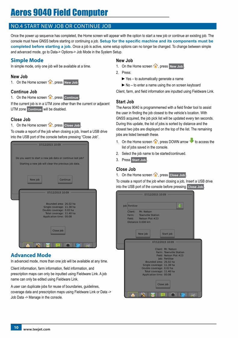
Once the power up sequence has completed, the Home screen will appear with the option to start a new job or continue an existing job. The console must have GNSS before starting or continuing a job. Setup for the specific machine and its components must be completed before starting a job. Once a job is active, some setup options can no longer be changed. To change between simple and advanced mode, go to Data-> Options-> Job Mode in the System Setup.
Simple ModeIn simple mode, only one job will be available at a time.
New Job1. On the Home screen , press New Job .
Continue Job1. On the Home screen , press Continue .If the current job is in a UTM zone other than the current or adjacent UTM zone Continue will be disabled.
Close Job1. On the Home screen , press Close Job .To create a report of the job when closing a job, Insert a USB drive into the USB port of the console before pressing “Close Job”.
Advanced ModeIn advanced mode, more than one job will be available at any time.
Client information, farm information, field information, and prescription maps can only be inputted using Fieldware Link. A job name can only be edited using Fieldware Link.
A user can duplicate jobs for reuse of boundaries, guidelines, coverage data and prescription maps using Fieldware Link or Data -> Job Data -> Manage in the console.
New Job1. On the Home screen , press New Job .2. Press:
►Yes – to automatically generate a name►No – to enter a name using the on screen keyboard
Client, farm, and field information are inputted using Fieldware Link.
Start JobThe Aeros 9040 is programmemed with a field finder tool to assist the user in finding the job closest to the vehicle’s location. With GNSS acquired, the job pick list will be updated every ten seconds. During this update, the list of jobs is sorted by distance and the closest two jobs are displayed on the top of the list. The remaining jobs are listed beneath these.
1. On the Home screen , press DOWN arrow to access the list of jobs saved in the console.
2. Select the job name to be started/continued.3. Press Start Job .
Close Job1. On the Home screen , press Close Job .To create a report of the job when closing a job, Insert a USB drive into the USB port of the console before pressing Close Job .
1198-01504-EN R1
Aeros 9040 Field ComputerNO.5 SET UP GUIDANCE
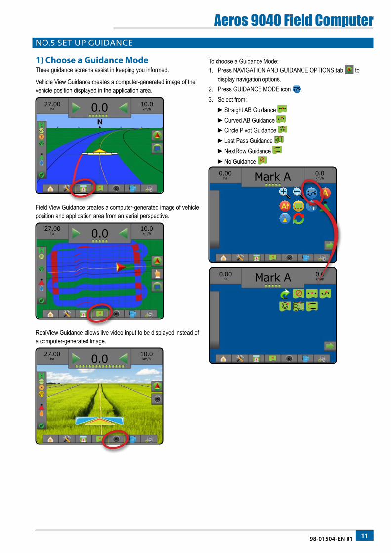
1) Choose a Guidance ModeThree guidance screens assist in keeping you informed.
Vehicle View Guidance creates a computer-generated image of the vehicle position displayed in the application area.
10.0km/h
27.00ha 0.0
Field View Guidance creates a computer-generated image of vehicle position and application area from an aerial perspective.
27.00ha
10.0km/h0.0
RealView Guidance allows live video input to be displayed instead of a computer-generated image.
27.00ha
10.0km/h0.0
To choose a Guidance Mode:1. Press NAVIGATION AND GUIDANCE OPTIONS tab to
display navigation options.2. Press GUIDANCE MODE icon .3. Select from:
►Straight AB Guidance ►Curved AB Guidance ►Circle Pivot Guidance ►Last Pass Guidance ►NextRow Guidance ►No Guidance
0.0km/h
0.00ha Mark A
0.0km/h
0.00ha Mark A
A
12 www.teejet.com
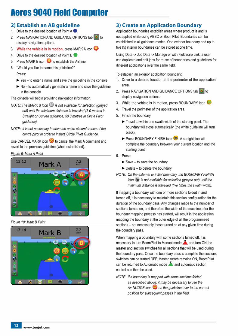
Aeros 9040 Field Computer2) Establish an AB guideline1. Drive to the desired location of Point A .2. Press NAVIGATION AND GUIDANCE OPTIONS tab to
display navigation options.3. While the vehicle is in motion, press MARK A icon A .4. Drive to the desired location of Point B .5. Press MARK B icon B to establish the AB line.6. “Would you like to name this guideline?”
Press:►Yes – to enter a name and save the guideline in the console►No – to automatically generate a name and save the guideline
in the consoleThe console will begin providing navigation information.
NOTE: The MARK B Icon B is not available for selection (greyed out) until the minimum distance is travelled (3.0 metres in Straight or Curved guidance, 50.0 metres in Circle Pivot guidance).
NOTE: It is not necessary to drive the entire circumference of the centre pivot in order to initiate Circle Pivot Guidance.
Use CANCEL MARK icon to cancel the Mark A command and revert to the previous guideline (when established).
Figure 9: Mark A Point
13:12
7.2km/hMark A
A
Figure 10: Mark B Point
13:14
7.2km/hMark B
B
3) Create an Application BoundaryApplication boundaries establish areas where product is and is not applied while using ABSC or BoomPilot. Boundaries can be established in all guidance modes. One exterior boundary and up to five (5) interior boundaries can be stored at one time.
Using Data -> Job Data -> Manage or with Fieldware Link, a user can duplicate and edit jobs for reuse of boundaries and guidelines for different applications over the same field.
To establish an exterior application boundary:1. Drive to a desired location at the perimeter of the application
area.2. Press NAVIGATION AND GUIDANCE OPTIONS tab to
display navigation options.3. While the vehicle is in motion, press BOUNDARY icon .4. Travel the perimeter of the application area.5. Finish the boundary:
►Travel to within one swath width of the starting point. The boundary will close automatically (the white guideline will turn black).
►Press BOUNDARY FINISH icon . A straight line will complete the boundary between your current location and the starting point.
6. Press:►Save – to save the boundary►Delete – to delete the boundary
NOTE: On the external or initial boundary, the BOUNDARY FINISH icon is not available for selection (greyed out) until the minimum distance is travelled (five times the swath width).
If mapping a boundary with one or more sections folded in and turned off, it is necessary to maintain this section configuration for the duration of the boundary pass. Any changes made to the number of sections turned on, and therefore the width of the machine after the boundary mapping process has started, will result in the application mapping the boundary at the outer edge of all the programmeed sections – not necessarily those turned on at any given time during the boundary pass.
When mapping a boundary with some sections turned off, it is necessary to turn BoomPilot to Manual mode and turn ON the master and section switches for all sections that will be used during the boundary pass. Once the boundary pass is complete the sections switches can be turned OFF, Master switch remains ON, BoomPilot can be returned to Automatic mode and automatic section control can then be used.
NOTE: If a boundary is mapped with some sections folded as described above, it may be necessary to use the A+ NUDGE icon A on the guideline over to the correct position for subsequent passes in the field.
1398-01504-EN R1
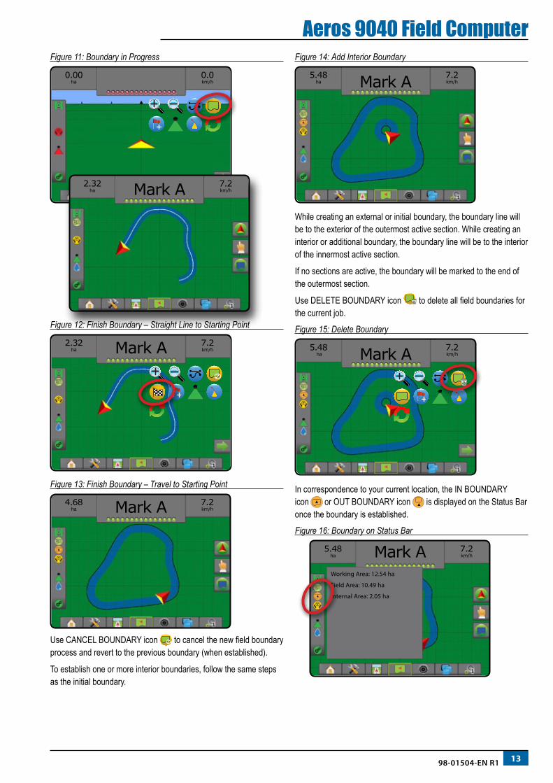
Aeros 9040 Field ComputerFigure 11: Boundary in Progress
0.00 ha
0.0km/h
2.32 ha
7.2km/hMark A
Figure 12: Finish Boundary – Straight Line to Starting Point
2.32 ha
7.2km/hMark A
Figure 13: Finish Boundary – Travel to Starting Point
4.68 ha
7.2km/hMark A
Use CANCEL BOUNDARY icon to cancel the new field boundary process and revert to the previous boundary (when established).
To establish one or more interior boundaries, follow the same steps as the initial boundary.
Figure 14: Add Interior Boundary
5.48 ha
7.2km/hMark A
While creating an external or initial boundary, the boundary line will be to the exterior of the outermost active section. While creating an interior or additional boundary, the boundary line will be to the interior of the innermost active section.
If no sections are active, the boundary will be marked to the end of the outermost section.
Use DELETE BOUNDARY icon to delete all field boundaries for the current job.
Figure 15: Delete Boundary
5.48 ha
7.2km/hMark A
In correspondence to your current location, the IN BOUNDARY icon or OUT BOUNDARY icon is displayed on the Status Bar once the boundary is established.
Figure 16: Boundary on Status Bar
5.48ha
7.2km/hMark A
Working Area: 12.54 ha
Field Area: 10.49 ha
Internal Area: 2.05 ha
14 www.teejet.com
Aeros 9040 Field ComputerADD RATE CONTROL
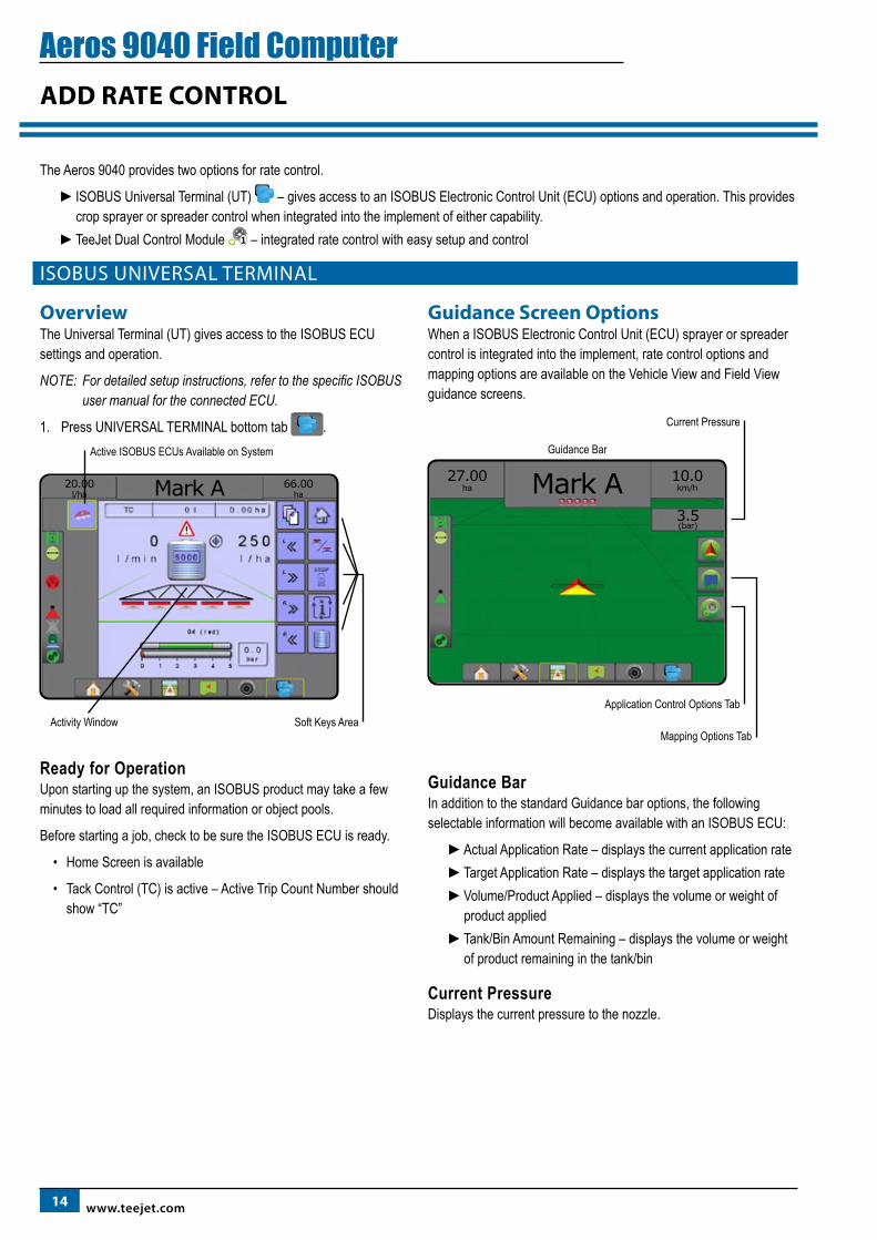
The Aeros 9040 provides two options for rate control.
►ISOBUS Universal Terminal (UT) – gives access to an ISOBUS Electronic Control Unit (ECU) options and operation. This provides crop sprayer or spreader control when integrated into the implement of either capability.
►TeeJet Dual Control Module – integrated rate control with easy setup and control
ISOBUS UNIVERSAL TERMINAL
OverviewThe Universal Terminal (UT) gives access to the ISOBUS ECU settings and operation.
NOTE: For detailed setup instructions, refer to the specific ISOBUS user manual for the connected ECU.
1. Press UNIVERSAL TERMINAL bottom tab .
20.00l/ha
66.00haMark A
Soft Keys Area
Active ISOBUS ECUs Available on System
Activity Window
Ready for OperationUpon starting up the system, an ISOBUS product may take a few minutes to load all required information or object pools.
Before starting a job, check to be sure the ISOBUS ECU is ready.
• Home Screen is available
• Tack Control (TC) is active – Active Trip Count Number should show “TC”
Guidance Screen OptionsWhen a ISOBUS Electronic Control Unit (ECU) sprayer or spreader control is integrated into the implement, rate control options and mapping options are available on the Vehicle View and Field View guidance screens.
Application Control Options Tab
Current Pressure
Mapping Options Tab
10.0km/h
3.5(bar)
27.00ha Mark A
Guidance Bar
Guidance BarIn addition to the standard Guidance bar options, the following selectable information will become available with an ISOBUS ECU:
►Actual Application Rate – displays the current application rate ►Target Application Rate – displays the target application rate►Volume/Product Applied – displays the volume or weight of
product applied►Tank/Bin Amount Remaining – displays the volume or weight
of product remaining in the tank/bin
Current PressureDisplays the current pressure to the nozzle.
1598-01504-EN R1
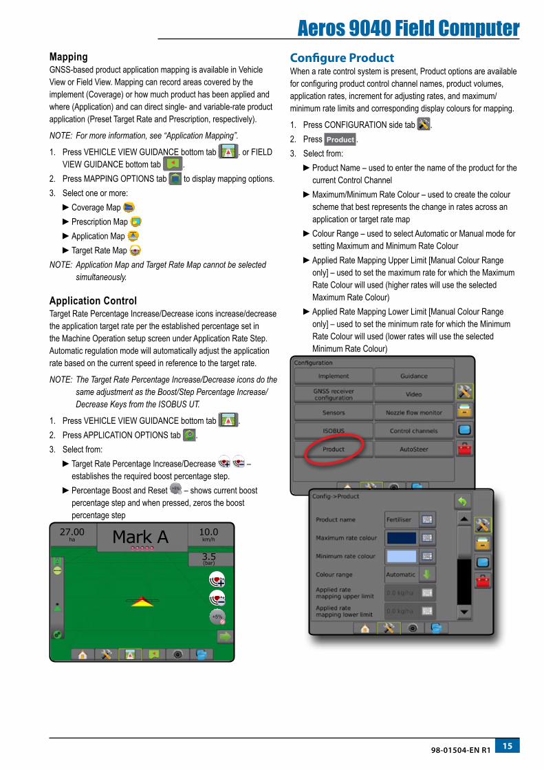
Aeros 9040 Field ComputerMappingGNSS-based product application mapping is available in Vehicle View or Field View. Mapping can record areas covered by the implement (Coverage) or how much product has been applied and where (Application) and can direct single- and variable-rate product application (Preset Target Rate and Prescription, respectively).
NOTE: For more information, see “Application Mapping”.
1. Press VEHICLE VIEW GUIDANCE bottom tab . or FIELD VIEW GUIDANCE bottom tab .
2. Press MAPPING OPTIONS tab to display mapping options.3. Select one or more:
►Coverage Map ►Prescription Map ►Application Map ►Target Rate Map
NOTE: Application Map and Target Rate Map cannot be selected simultaneously.
Application Control Target Rate Percentage Increase/Decrease icons increase/decrease the application target rate per the established percentage set in the Machine Operation setup screen under Application Rate Step. Automatic regulation mode will automatically adjust the application rate based on the current speed in reference to the target rate.
NOTE: The Target Rate Percentage Increase/Decrease icons do the same adjustment as the Boost/Step Percentage Increase/Decrease Keys from the ISOBUS UT.
1. Press VEHICLE VIEW GUIDANCE bottom tab .2. Press APPLICATION OPTIONS tab .3. Select from:
►Target Rate Percentage Increase/Decrease – establishes the required boost percentage step.
►Percentage Boost and Reset +5% – shows current boost percentage step and when pressed, zeros the boost percentage step
+5%
10.0km/h
3.5(bar)
27.00ha Mark A
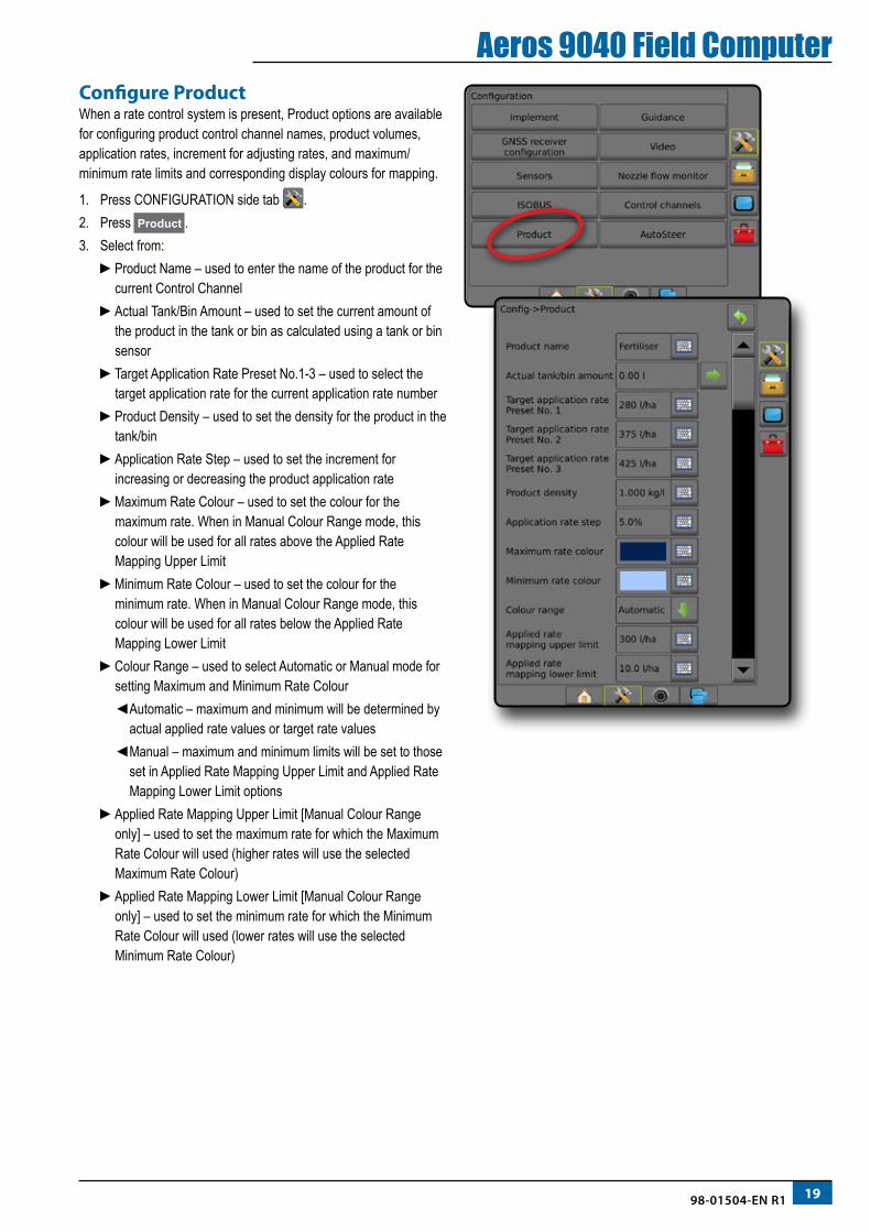
Configure ProductWhen a rate control system is present, Product options are available for configuring product control channel names, product volumes, application rates, increment for adjusting rates, and maximum/minimum rate limits and corresponding display colours for mapping.
1. Press CONFIGURATION side tab .2. Press Product .3. Select from:
►Product Name – used to enter the name of the product for the current Control Channel
►Maximum/Minimum Rate Colour – used to create the colour scheme that best represents the change in rates across an application or target rate map
►Colour Range – used to select Automatic or Manual mode for setting Maximum and Minimum Rate Colour
►Applied Rate Mapping Upper Limit [Manual Colour Range only] – used to set the maximum rate for which the Maximum Rate Colour will used (higher rates will use the selected Maximum Rate Colour)
►Applied Rate Mapping Lower Limit [Manual Colour Range only] – used to set the minimum rate for which the Minimum Rate Colour will used (lower rates will use the selected Minimum Rate Colour)
16 www.teejet.com
Aeros 9040 Field ComputerTEEJET DUAL CONTROL MODULE
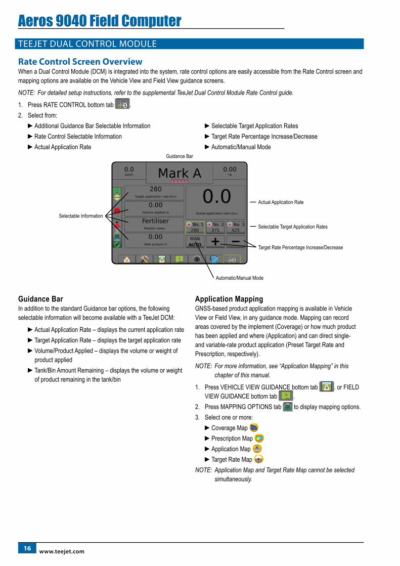
Rate Control Screen OverviewWhen a Dual Control Module (DCM) is integrated into the system, rate control options are easily accessible from the Rate Control screen and mapping options are available on the Vehicle View and Field View guidance screens.
NOTE: For detailed setup instructions, refer to the supplemental TeeJet Dual Control Module Rate Control guide.
1. Press RATE CONTROL bottom tab .2. Select from:
►Additional Guidance Bar Selectable Information►Rate Control Selectable Information►Actual Application Rate
►Selectable Target Application Rates►Target Rate Percentage Increase/Decrease►Automatic/Manual Mode
Selectable Target Application Rates
Target Rate Percentage Increase/Decrease
Automatic/Manual Mode
Actual Application Rate
Selectable Information
Guidance Bar
Guidance BarIn addition to the standard Guidance bar options, the following selectable information will become available with a TeeJet DCM:
►Actual Application Rate – displays the current application rate ►Target Application Rate – displays the target application rate►Volume/Product Applied – displays the volume or weight of
product applied►Tank/Bin Amount Remaining – displays the volume or weight
of product remaining in the tank/bin
Application MappingGNSS-based product application mapping is available in Vehicle View or Field View, in any guidance mode. Mapping can record areas covered by the implement (Coverage) or how much product has been applied and where (Application) and can direct single- and variable-rate product application (Preset Target Rate and Prescription, respectively).
NOTE: For more information, see “Application Mapping” in this chapter of this manual.
1. Press VEHICLE VIEW GUIDANCE bottom tab . or FIELD VIEW GUIDANCE bottom tab .
2. Press MAPPING OPTIONS tab to display mapping options.3. Select one or more:
►Coverage Map ►Prescription Map ►Application Map ►Target Rate Map
NOTE: Application Map and Target Rate Map cannot be selected simultaneously.
1798-01504-EN R1
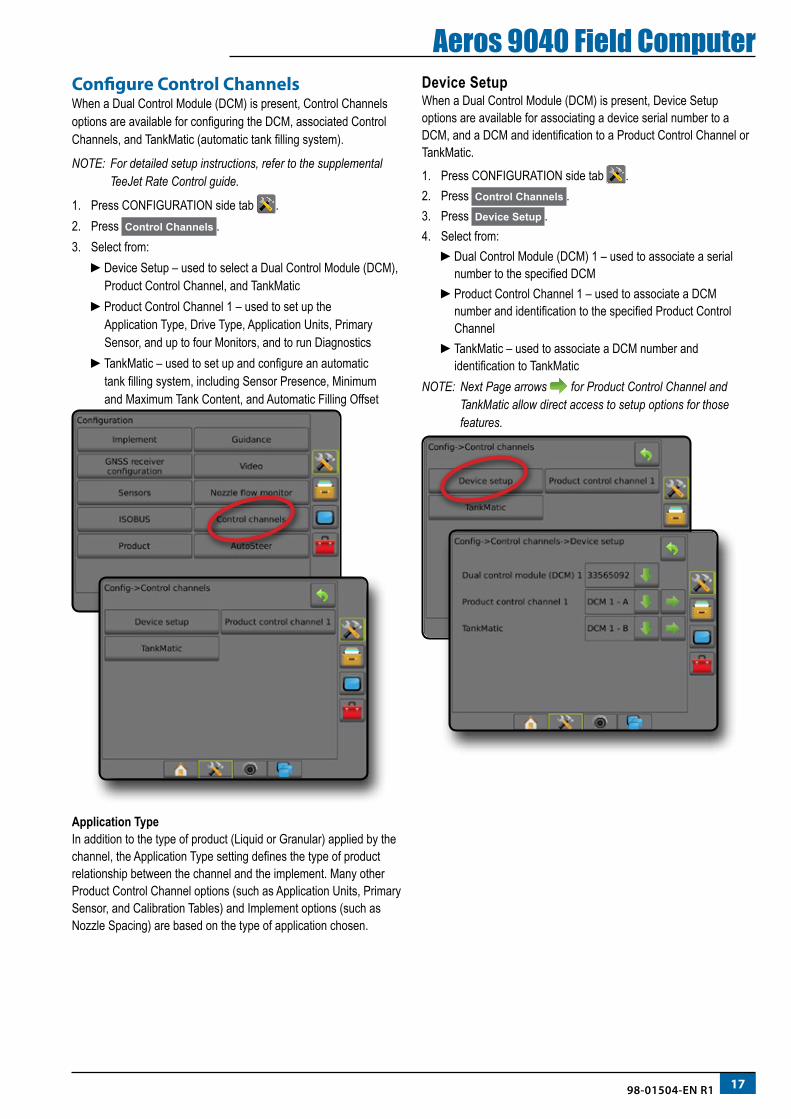
Aeros 9040 Field ComputerConfigure Control ChannelsWhen a Dual Control Module (DCM) is present, Control Channels options are available for configuring the DCM, associated Control Channels, and TankMatic (automatic tank filling system).
NOTE: For detailed setup instructions, refer to the supplemental TeeJet Rate Control guide.
1. Press CONFIGURATION side tab .2. Press Control Channels .3. Select from:
►Device Setup – used to select a Dual Control Module (DCM), Product Control Channel, and TankMatic
►Product Control Channel 1 – used to set up the Application Type, Drive Type, Application Units, Primary Sensor, and up to four Monitors, and to run Diagnostics
►TankMatic – used to set up and configure an automatic tank filling system, including Sensor Presence, Minimum and Maximum Tank Content, and Automatic Filling Offset
Application TypeIn addition to the type of product (Liquid or Granular) applied by the channel, the Application Type setting defines the type of product relationship between the channel and the implement. Many other Product Control Channel options (such as Application Units, Primary Sensor, and Calibration Tables) and Implement options (such as Nozzle Spacing) are based on the type of application chosen.
Device SetupWhen a Dual Control Module (DCM) is present, Device Setup options are available for associating a device serial number to a DCM, and a DCM and identification to a Product Control Channel or TankMatic.
1. Press CONFIGURATION side tab .2. Press Control Channels .3. Press Device Setup .4. Select from:
►Dual Control Module (DCM) 1 – used to associate a serial number to the specified DCM
►Product Control Channel 1 – used to associate a DCM number and identification to the specified Product Control Channel
►TankMatic – used to associate a DCM number and identification to TankMatic
NOTE: Next Page arrows for Product Control Channel and TankMatic allow direct access to setup options for those features.
18 www.teejet.com
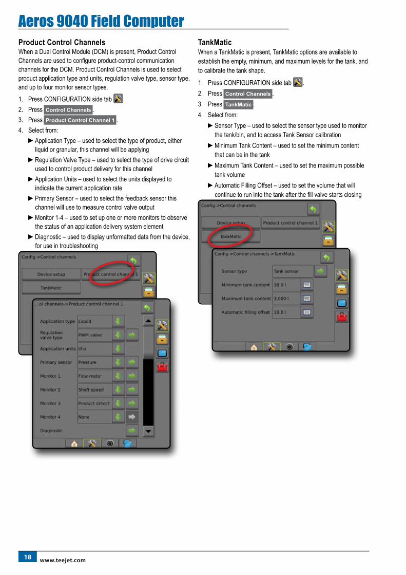
Aeros 9040 Field ComputerProduct Control ChannelsWhen a Dual Control Module (DCM) is present, Product Control Channels are used to configure product-control communication channels for the DCM. Product Control Channels is used to select product application type and units, regulation valve type, sensor type, and up to four monitor sensor types.
1. Press CONFIGURATION side tab .2. Press Control Channels .3. Press Product Control Channel 1 .4. Select from:
►Application Type – used to select the type of product, either liquid or granular, this channel will be applying
►Regulation Valve Type – used to select the type of drive circuit used to control product delivery for this channel
►Application Units – used to select the units displayed to indicate the current application rate
►Primary Sensor – used to select the feedback sensor this channel will use to measure control valve output
►Monitor 1-4 – used to set up one or more monitors to observe the status of an application delivery system element
►Diagnostic – used to display unformatted data from the device, for use in troubleshooting
TankMatic When a TankMatic is present, TankMatic options are available to establish the empty, minimum, and maximum levels for the tank, and to calibrate the tank shape.
1. Press CONFIGURATION side tab .2. Press Control Channels .3. Press TankMatic .4. Select from:
►Sensor Type – used to select the sensor type used to monitor the tank/bin, and to access Tank Sensor calibration
►Minimum Tank Content – used to set the minimum content that can be in the tank
►Maximum Tank Content – used to set the maximum possible tank volume
►Automatic Filling Offset – used to set the volume that will continue to run into the tank after the fill valve starts closing
1998-01504-EN R1
Aeros 9040 Field ComputerConfigure ProductWhen a rate control system is present, Product options are available for configuring product control channel names, product volumes, application rates, increment for adjusting rates, and maximum/minimum rate limits and corresponding display colours for mapping.
1. Press CONFIGURATION side tab .2. Press Product .3. Select from:
►Product Name – used to enter the name of the product for the current Control Channel
►Actual Tank/Bin Amount – used to set the current amount of the product in the tank or bin as calculated using a tank or bin sensor
►Target Application Rate Preset No.1-3 – used to select the target application rate for the current application rate number
►Product Density – used to set the density for the product in the tank/bin
►Application Rate Step – used to set the increment for increasing or decreasing the product application rate
►Maximum Rate Colour – used to set the colour for the maximum rate. When in Manual Colour Range mode, this colour will be used for all rates above the Applied Rate Mapping Upper Limit
►Minimum Rate Colour – used to set the colour for the minimum rate. When in Manual Colour Range mode, this colour will be used for all rates below the Applied Rate Mapping Lower Limit
►Colour Range – used to select Automatic or Manual mode for setting Maximum and Minimum Rate Colour
◄ Automatic – maximum and minimum will be determined by actual applied rate values or target rate values
◄ Manual – maximum and minimum limits will be set to those set in Applied Rate Mapping Upper Limit and Applied Rate Mapping Lower Limit options
►Applied Rate Mapping Upper Limit [Manual Colour Range only] – used to set the maximum rate for which the Maximum Rate Colour will used (higher rates will use the selected Maximum Rate Colour)
►Applied Rate Mapping Lower Limit [Manual Colour Range only] – used to set the minimum rate for which the Minimum Rate Colour will used (lower rates will use the selected Minimum Rate Colour)
20 www.teejet.com
Aeros 9040 Field ComputerAPPLICATION MAPPING
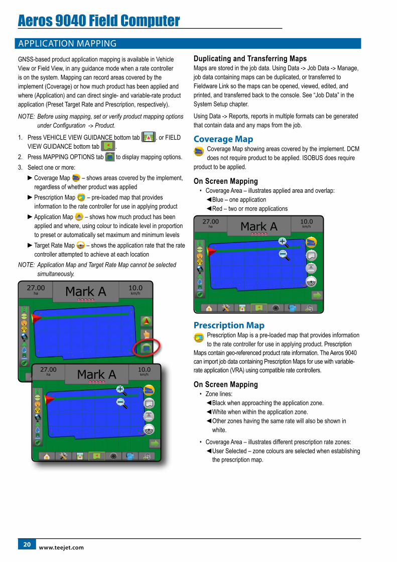
GNSS-based product application mapping is available in Vehicle View or Field View, in any guidance mode when a rate controller is on the system. Mapping can record areas covered by the implement (Coverage) or how much product has been applied and where (Application) and can direct single- and variable-rate product application (Preset Target Rate and Prescription, respectively).
NOTE: Before using mapping, set or verify product mapping options under Configuration -> Product.
1. Press VEHICLE VIEW GUIDANCE bottom tab . or FIELD VIEW GUIDANCE bottom tab .
2. Press MAPPING OPTIONS tab to display mapping options.3. Select one or more:
►Coverage Map – shows areas covered by the implement, regardless of whether product was applied
►Prescription Map – pre-loaded map that provides information to the rate controller for use in applying product
►Application Map – shows how much product has been applied and where, using colour to indicate level in proportion to preset or automatically set maximum and minimum levels
►Target Rate Map – shows the application rate that the rate controller attempted to achieve at each location
NOTE: Application Map and Target Rate Map cannot be selected simultaneously.
10.0km/h
27.00ha Mark A
27.00ha
10.0km/hMark A
Duplicating and Transferring MapsMaps are stored in the job data. Using Data -> Job Data -> Manage, job data containing maps can be duplicated, or transferred to Fieldware Link so the maps can be opened, viewed, edited, and printed, and transferred back to the console. See “Job Data” in the System Setup chapter.
Using Data -> Reports, reports in multiple formats can be generated that contain data and any maps from the job.
Coverage MapCoverage Map showing areas covered by the implement. DCM does not require product to be applied. ISOBUS does require
product to be applied.
On Screen Mapping• Coverage Area – illustrates applied area and overlap:
◄Blue – one application ◄Red – two or more applications
27.00ha
10.0km/hMark A
Prescription MapPrescription Map is a pre-loaded map that provides information to the rate controller for use in applying product. Prescription
Maps contain geo-referenced product rate information. The Aeros 9040 can import job data containing Prescription Maps for use with variable-rate application (VRA) using compatible rate controllers.
On Screen Mapping• Zone lines:
◄Black when approaching the application zone. ◄White when within the application zone. ◄ Other zones having the same rate will also be shown in
white.
• Coverage Area – illustrates different prescription rate zones: ◄ User Selected – zone colours are selected when establishing
the prescription map.
2198-01504-EN R1
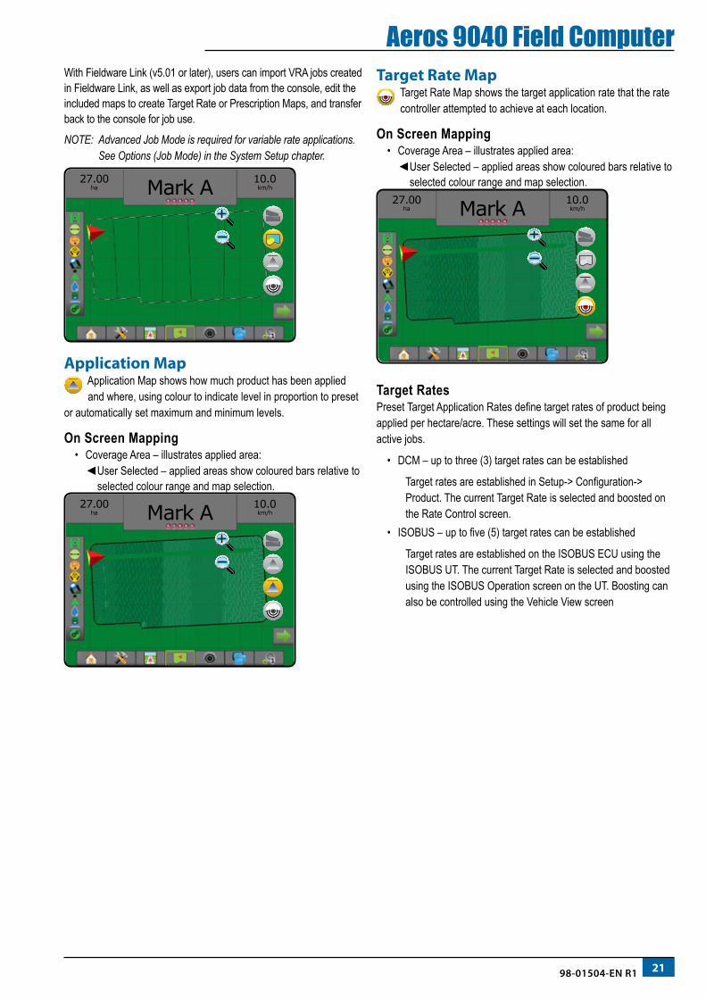
Aeros 9040 Field ComputerWith Fieldware Link (v5.01 or later), users can import VRA jobs created in Fieldware Link, as well as export job data from the console, edit the included maps to create Target Rate or Prescription Maps, and transfer back to the console for job use.
NOTE: Advanced Job Mode is required for variable rate applications. See Options (Job Mode) in the System Setup chapter.
27.00ha
10.0km/hMark A
Application MapApplication Map shows how much product has been applied and where, using colour to indicate level in proportion to preset
or automatically set maximum and minimum levels.
On Screen Mapping• Coverage Area – illustrates applied area:
◄ User Selected – applied areas show coloured bars relative to selected colour range and map selection.
27.00ha
10.0km/hMark A
Target Rate MapTarget Rate Map shows the target application rate that the rate controller attempted to achieve at each location.
On Screen Mapping• Coverage Area – illustrates applied area:
◄ User Selected – applied areas show coloured bars relative to selected colour range and map selection.
27.00ha
10.0km/hMark A
Target RatesPreset Target Application Rates define target rates of product being applied per hectare/acre. These settings will set the same for all active jobs.
• DCM – up to three (3) target rates can be established
Target rates are established in Setup-> Configuration-> Product. The current Target Rate is selected and boosted on the Rate Control screen.
• ISOBUS – up to five (5) target rates can be established
Target rates are established on the ISOBUS ECU using the ISOBUS UT. The current Target Rate is selected and boosted using the ISOBUS Operation screen on the UT. Boosting can also be controlled using the Vehicle View screen
22 www.teejet.com
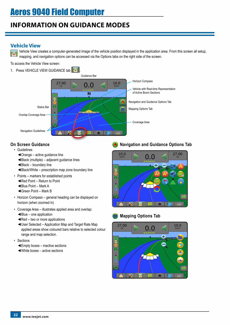
Aeros 9040 Field ComputerINFORMATION ON GUIDANCE MODES
Vehicle ViewVehicle View creates a computer-generated image of the vehicle position displayed in the application area. From this screen all setup, mapping, and navigation options can be accessed via the Options tabs on the right side of the screen.
To access the Vehicle View screen:
1. Press VEHICLE VIEW GUIDANCE tab .
10.0km/h
27.00ha 0.0
Status Bar
Horizon CompassGuidance Bar
Coverage Area
Overlap Coverage Area
Navigation Guidelines
Vehicle with Real-time Representation of Active Boom Sections
Navigation and Guidance Options Tab
Mapping Options Tab
On Screen Guidance• Guidelines
◄Orange – active guidance line ◄Black (multiple) – adjacent guidance lines ◄Black – boundary line ◄Black/White – prescription map zone boundary line
• Points – markers for established points ◄Red Point – Return to Point ◄Blue Point – Mark A ◄Green Point – Mark B
• Horizon Compass – general heading can be displayed on horizon (when zoomed in)
• Coverage Area – illustrates applied area and overlap: ◄Blue – one application ◄Red – two or more applications ◄ User Selected – Application Map and Target Rate Map
applied areas show coloured bars relative to selected colour range and map selection.
• Sections ◄Empty boxes – inactive sections ◄White boxes – active sections
Navigation and Guidance Options Tab
10.0km/h
27.00ha0.0A
A
Mapping Options Tab
27.00ha
10.0km/h0.0
2398-01504-EN R1
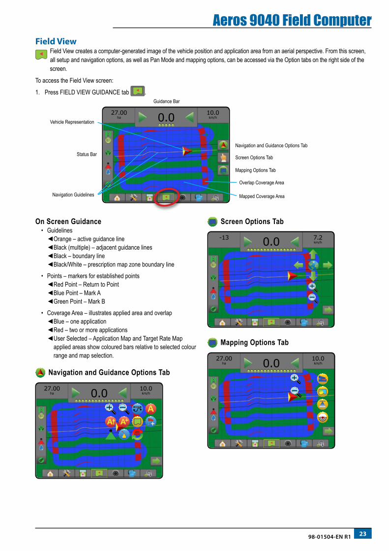
Aeros 9040 Field ComputerField View
Field View creates a computer-generated image of the vehicle position and application area from an aerial perspective. From this screen, all setup and navigation options, as well as Pan Mode and mapping options, can be accessed via the Option tabs on the right side of the screen.
To access the Field View screen:
1. Press FIELD VIEW GUIDANCE tab .
27.00ha
10.0km/h0.0
Overlap Coverage Area
Status Bar Screen Options Tab
Mapping Options Tab
Guidance Bar
Mapped Coverage AreaNavigation Guidelines
Vehicle Representation
Navigation and Guidance Options Tab
On Screen Guidance• Guidelines
◄Orange – active guidance line ◄Black (multiple) – adjacent guidance lines ◄Black – boundary line ◄Black/White – prescription map zone boundary line
• Points – markers for established points ◄Red Point – Return to Point ◄Blue Point – Mark A ◄Green Point – Mark B
• Coverage Area – illustrates applied area and overlap ◄Blue – one application ◄Red – two or more applications ◄ User Selected – Application Map and Target Rate Map
applied areas show coloured bars relative to selected colour range and map selection.
Navigation and Guidance Options Tab
27.00ha
10.0km/h0.0
AA
Screen Options Tab
-13
7.2km/h0.0
Mapping Options Tab
27.00ha
10.0km/h0.0
24 www.teejet.com
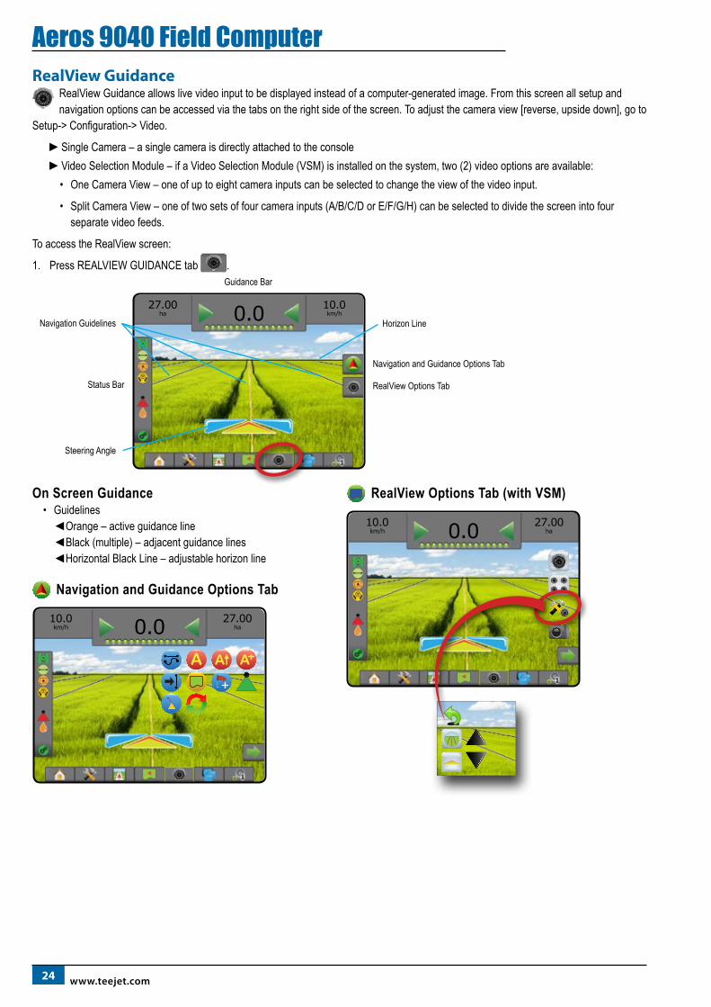
Aeros 9040 Field ComputerRealView Guidance
RealView Guidance allows live video input to be displayed instead of a computer-generated image. From this screen all setup and navigation options can be accessed via the tabs on the right side of the screen. To adjust the camera view [reverse, upside down], go to
Setup-> Configuration-> Video.
►Single Camera – a single camera is directly attached to the console►Video Selection Module – if a Video Selection Module (VSM) is installed on the system, two (2) video options are available:
• One Camera View – one of up to eight camera inputs can be selected to change the view of the video input.
• Split Camera View – one of two sets of four camera inputs (A/B/C/D or E/F/G/H) can be selected to divide the screen into four separate video feeds.
To access the RealView screen:
1. Press REALVIEW GUIDANCE tab .
27.00ha
10.0km/h0.0
Status Bar
Guidance Bar
Navigation Guidelines
Steering Angle
Navigation and Guidance Options Tab
Horizon Line
RealView Options Tab
On Screen Guidance• Guidelines
◄Orange – active guidance line ◄Black (multiple) – adjacent guidance lines ◄Horizontal Black Line – adjustable horizon line
Navigation and Guidance Options Tab
10.0km/h
27.00ha0.0
A A
RealView Options Tab (with VSM)
10.0km/h
27.00ha0.0
2598-01504-EN R1
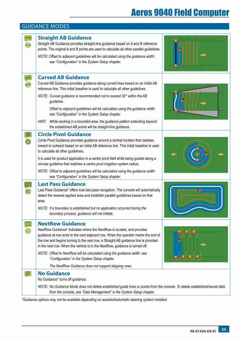
Aeros 9040 Field ComputerGUIDANCE MODES
Straight AB GuidanceStraight AB Guidance provides straight-line guidance based on A and B reference points. The original A and B points are used to calculate all other parallel guidelines.
NOTE: Offset to adjacent guidelines will be calculated using the guidance width: see “Configuration” in the System Setup chapter.
Curved AB GuidanceCurved AB Guidance provides guidance along curved lines based on an initial AB reference line. This initial baseline is used to calculate all other guidelines.
NOTE: Curved guidance is recommended not to exceed 30° within the AB guideline.
Offset to adjacent guidelines will be calculated using the guidance width: see “Configuration” in the System Setup chapter.
HINT: While working in a bounded area, the guidance pattern extending beyond the established AB points will be straight-line guidance.
Circle Pivot GuidanceCircle Pivot Guidance provides guidance around a central location that radiates inward or outward based on an initial AB reference line. This initial baseline is used to calculate all other guidelines.
It is used for product application in a centre pivot field while being guided along a circular guideline that matches a centre pivot irrigation system radius.
NOTE: Offset to adjacent guidelines will be calculated using the guidance width: see “Configuration” in the System Setup chapter.
Last Pass GuidanceLast Pass Guidance* offers true last-pass navigation. The console will automatically detect the nearest applied area and establish parallel guidelines based on that area.
NOTE: If a boundary is established but no application occurred during the boundary process, guidance will not initiate.
NextRow GuidanceNextRow Guidance* indicates where the NextRow is located, and provides guidance at row ends to the next adjacent row. When the operator marks the end of the row and begins turning to the next row, a Straight AB guidance line is provided in the next row. When the vehicle is in the NextRow, guidance is turned off.
NOTE: Offset to NextRow will be calculated using the guidance width: see “Configuration” in the System Setup chapter.
The NextRow Guidance does not support skipping rows.
No GuidanceNo Guidance* turns off guidance.
NOTE: No Guidance Mode does not delete established guide lines or points from the console. To delete established/saved data from the console, see “Data Management” in the System Setup chapter.
*Guidance options may not be available depending on assisted/automatic steering system installed.
26 www.teejet.com
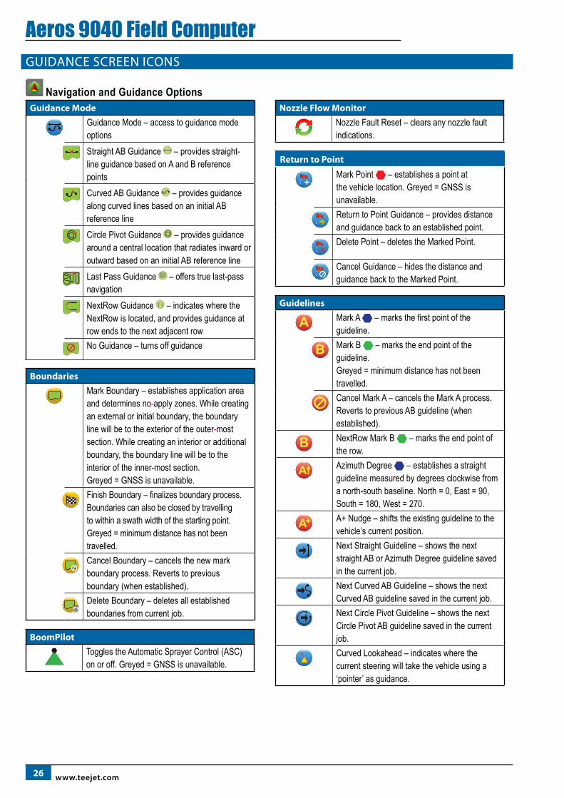
Aeros 9040 Field ComputerGUIDANCE SCREEN ICONS
Navigation and Guidance OptionsGuidance Mode
Guidance Mode – access to guidance mode optionsStraight AB Guidance – provides straight-line guidance based on A and B reference pointsCurved AB Guidance – provides guidance along curved lines based on an initial AB reference lineCircle Pivot Guidance – provides guidance around a central location that radiates inward or outward based on an initial AB reference lineLast Pass Guidance – offers true last-pass navigationNextRow Guidance – indicates where the NextRow is located, and provides guidance at row ends to the next adjacent rowNo Guidance – turns off guidance
Boundaries
Mark Boundary – establishes application area and determines no-apply zones. While creating an external or initial boundary, the boundary line will be to the exterior of the outer-most section. While creating an interior or additional boundary, the boundary line will be to the interior of the inner-most section. Greyed = GNSS is unavailable.Finish Boundary – finalizes boundary process. Boundaries can also be closed by travelling to within a swath width of the starting point. Greyed = minimum distance has not been travelled.Cancel Boundary – cancels the new mark boundary process. Reverts to previous boundary (when established).Delete Boundary – deletes all established boundaries from current job.
BoomPilot Toggles the Automatic Sprayer Control (ASC) on or off. Greyed = GNSS is unavailable.
Nozzle Flow Monitor Nozzle Fault Reset – clears any nozzle fault indications.
Return to Point
Mark Point – establishes a point at the vehicle location. Greyed = GNSS is unavailable.Return to Point Guidance – provides distance and guidance back to an established point. Delete Point – deletes the Marked Point.
Cancel Guidance – hides the distance and guidance back to the Marked Point.
Guidelines
A Mark A – marks the first point of the guideline.
B Mark B – marks the end point of the guideline. Greyed = minimum distance has not been travelled.Cancel Mark A – cancels the Mark A process. Reverts to previous AB guideline (when established).
B NextRow Mark B – marks the end point of the row.Azimuth Degree – establishes a straight guideline measured by degrees clockwise from a north-south baseline. North = 0, East = 90, South = 180, West = 270.
A A+ Nudge – shifts the existing guideline to the vehicle’s current position.Next Straight Guideline – shows the next straight AB or Azimuth Degree guideline saved in the current job.Next Curved AB Guideline – shows the next Curved AB guideline saved in the current job.Next Circle Pivot Guideline – shows the next Circle Pivot AB guideline saved in the current job.Curved Lookahead – indicates where the current steering will take the vehicle using a ‘pointer’ as guidance.
2798-01504-EN R1
Aeros 9040 Field Computer Screen Options
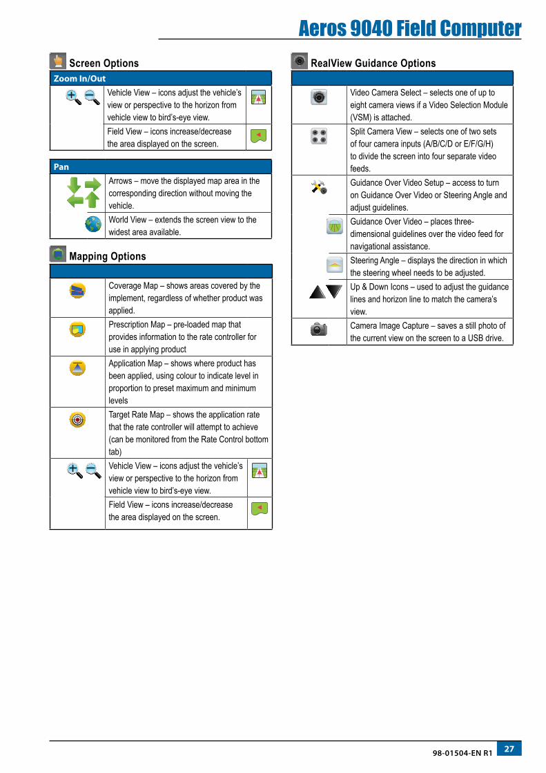
Zoom In/Out
Vehicle View – icons adjust the vehicle’s view or perspective to the horizon from vehicle view to bird’s-eye view.Field View – icons increase/decrease the area displayed on the screen.
PanArrows – move the displayed map area in the corresponding direction without moving the vehicle.World View – extends the screen view to the widest area available.
Mapping Options
Coverage Map – shows areas covered by the implement, regardless of whether product was applied.Prescription Map – pre-loaded map that provides information to the rate controller for use in applying productApplication Map – shows where product has been applied, using colour to indicate level in proportion to preset maximum and minimum levelsTarget Rate Map – shows the application rate that the rate controller will attempt to achieve (can be monitored from the Rate Control bottom tab)
Vehicle View – icons adjust the vehicle’s view or perspective to the horizon from vehicle view to bird’s-eye view.Field View – icons increase/decrease the area displayed on the screen.
RealView Guidance Options
Video Camera Select – selects one of up to eight camera views if a Video Selection Module (VSM) is attached.Split Camera View – selects one of two sets of four camera inputs (A/B/C/D or E/F/G/H) to divide the screen into four separate video feeds.Guidance Over Video Setup – access to turn on Guidance Over Video or Steering Angle and adjust guidelines.Guidance Over Video – places three-dimensional guidelines over the video feed for navigational assistance.Steering Angle – displays the direction in which the steering wheel needs to be adjusted.Up & Down Icons – used to adjust the guidance lines and horizon line to match the camera’s view. Camera Image Capture – saves a still photo of the current view on the screen to a USB drive.
28 www.teejet.com
Aeros 9040 Field ComputerGUIDANCE BAR
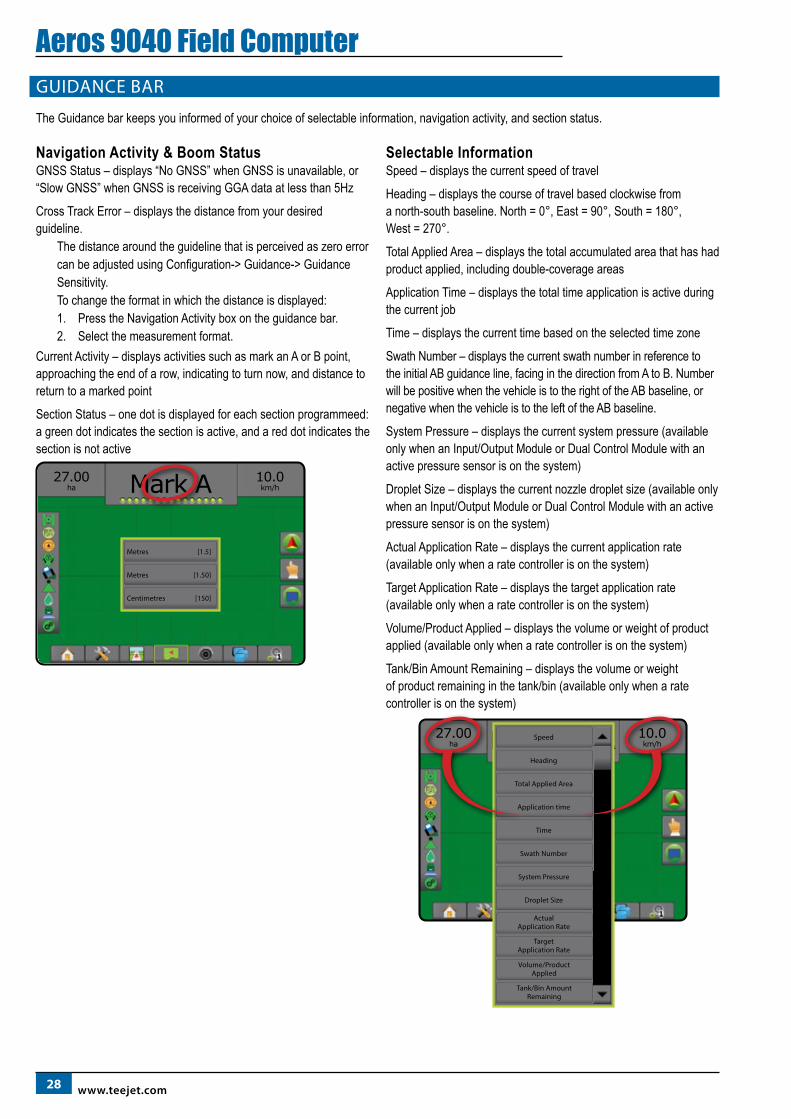
The Guidance bar keeps you informed of your choice of selectable information, navigation activity, and section status.
Navigation Activity & Boom StatusGNSS Status – displays “No GNSS” when GNSS is unavailable, or “Slow GNSS” when GNSS is receiving GGA data at less than 5Hz
Cross Track Error – displays the distance from your desired guideline.
The distance around the guideline that is perceived as zero error can be adjusted using Configuration-> Guidance-> Guidance Sensitivity.To change the format in which the distance is displayed:1. Press the Navigation Activity box on the guidance bar.2. Select the measurement format.
Current Activity – displays activities such as mark an A or B point, approaching the end of a row, indicating to turn now, and distance to return to a marked point
Section Status – one dot is displayed for each section programmeed: a green dot indicates the section is active, and a red dot indicates the section is not active
10.0km/h
27.00ha Mark A
Metres [1.5]
Centimetres [150]
Metres [1.50]
Selectable InformationSpeed – displays the current speed of travel
Heading – displays the course of travel based clockwise from a north-south baseline. North = 0°, East = 90°, South = 180°, West = 270°.
Total Applied Area – displays the total accumulated area that has had product applied, including double-coverage areas
Application Time – displays the total time application is active during the current job
Time – displays the current time based on the selected time zone
Swath Number – displays the current swath number in reference to the initial AB guidance line, facing in the direction from A to B. Number will be positive when the vehicle is to the right of the AB baseline, or negative when the vehicle is to the left of the AB baseline.
System Pressure – displays the current system pressure (available only when an Input/Output Module or Dual Control Module with an active pressure sensor is on the system)
Droplet Size – displays the current nozzle droplet size (available only when an Input/Output Module or Dual Control Module with an active pressure sensor is on the system)
Actual Application Rate – displays the current application rate (available only when a rate controller is on the system)
Target Application Rate – displays the target application rate (available only when a rate controller is on the system)
Volume/Product Applied – displays the volume or weight of product applied (available only when a rate controller is on the system)
Tank/Bin Amount Remaining – displays the volume or weight of product remaining in the tank/bin (available only when a rate controller is on the system)
10.0km/h
27.00ha Markiere ASpeed
Total Applied Area
Time
System Pressure
Actual Application Rate
Droplet Size
Target Application Rate
Heading
Application time
Swath Number
Volume/Product Applied
Tank/Bin Amount Remaining
2998-01504-EN R1
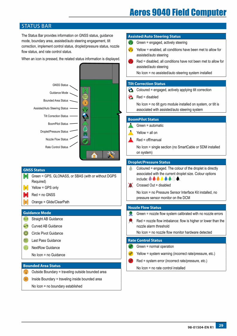
Aeros 9040 Field ComputerSTATUS BAR
The Status Bar provides information on GNSS status, guidance mode, boundary area, assisted/auto steering engagement, tilt correction, implement control status, droplet/pressure status, nozzle flow status, and rate control status.
When an icon is pressed, the related status information is displayed.
Tilt Correction Status
BoomPilot Status
Droplet/Pressure Status
Nozzle Flow Status
Rate Control Status
GNSS Status
Guidance Mode
Bounded Area Status
Assisted/Auto Steering Status
GNSS StatusGreen = GPS, GLONASS, or SBAS (with or without DGPS Required)Yellow = GPS only
Red = no GNSS
Orange = Glide/ClearPath
Guidance ModeStraight AB Guidance
Curved AB Guidance
Circle Pivot Guidance
Last Pass Guidance
NextRow Guidance
No Icon = no Guidance
Bounded Area StatusOutside Boundary = traveling outside bounded area
Inside Boundary = traveling inside bounded area
No Icon = no boundary established
Assisted/Auto Steering Status Green = engaged, actively steering
Yellow = enabled, all conditions have been met to allow for assisted/auto steeringRed = disabled, all conditions have not been met to allow for assisted/auto steeringNo Icon = no assisted/auto steering system installed
Tilt Correction Status Coloured = engaged, actively applying tilt correction
Red = disabled
No Icon = no tilt gyro module installed on system, or tilt is associated with assisted/auto steering system
BoomPilot Status Green = automatic
Yellow = all on
Red = off/manual
No Icon = single section (no SmartCable or SDM installed on system)
Droplet/Pressure Status Coloured = engaged. The colour of the droplet is directly associated with the current droplet size. Colour options include: .Crossed Out = disabled
No Icon = no Pressure Sensor Interface Kit installed, no pressure sensor monitor on the DCM
Nozzle Flow Status Green = nozzle flow system calibrated with no nozzle errors
Red = nozzle flow imbalance: flow is higher or lower than the nozzle alarm thresholdNo Icon = no nozzle flow monitor hardware detected
Rate Control Status Green = normal operation
Yellow = system warning (incorrect rate/pressure, etc.)
Red = system error (incorrect rate/pressure, etc.)
No Icon = no rate control installed
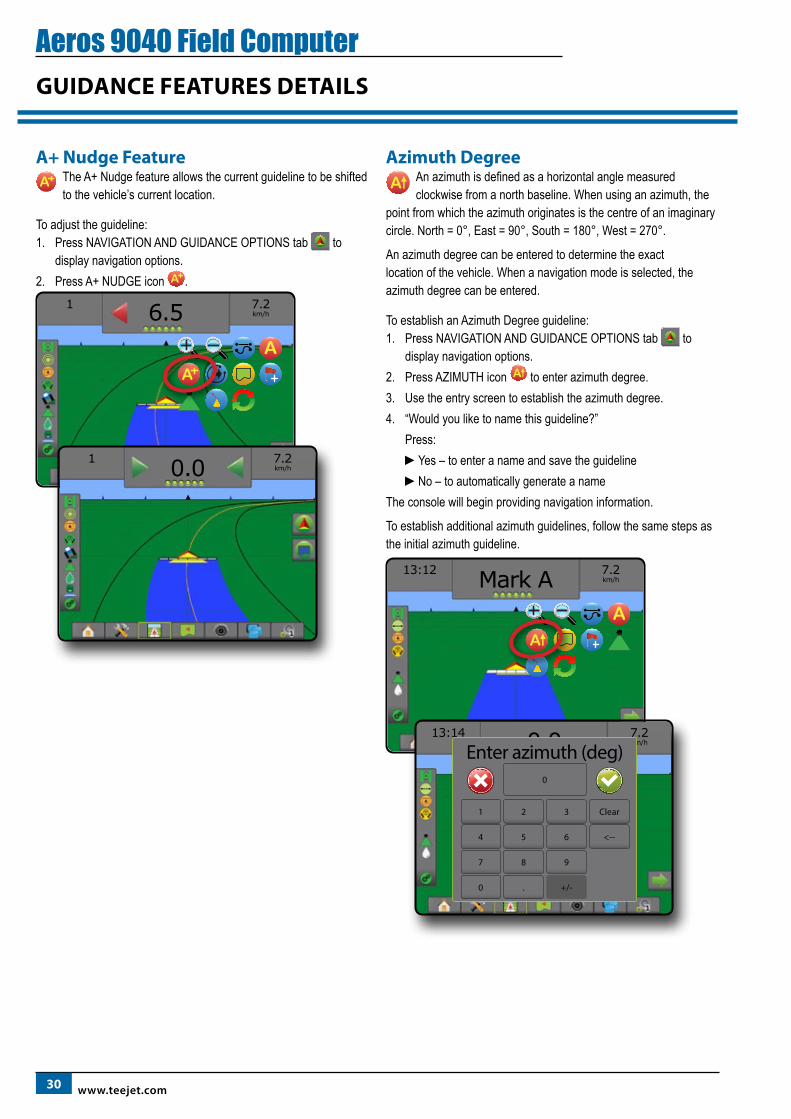
30 www.teejet.com
Aeros 9040 Field ComputerGUIDANCE FEATURES DETAILS
A+ Nudge FeatureA The A+ Nudge feature allows the current guideline to be shifted
to the vehicle’s current location.
To adjust the guideline:1. Press NAVIGATION AND GUIDANCE OPTIONS tab to
display navigation options.2. Press A+ NUDGE icon A .
1
7.2km/h6.5
AA
1
7.2km/h0.0
Azimuth DegreeAn azimuth is defined as a horizontal angle measured clockwise from a north baseline. When using an azimuth, the
point from which the azimuth originates is the centre of an imaginary circle. North = 0°, East = 90°, South = 180°, West = 270°.
An azimuth degree can be entered to determine the exact location of the vehicle. When a navigation mode is selected, the azimuth degree can be entered.
To establish an Azimuth Degree guideline:1. Press NAVIGATION AND GUIDANCE OPTIONS tab to
display navigation options.2. Press AZIMUTH icon to enter azimuth degree.3. Use the entry screen to establish the azimuth degree.4. “Would you like to name this guideline?”
Press:►Yes – to enter a name and save the guideline►No – to automatically generate a name
The console will begin providing navigation information.
To establish additional azimuth guidelines, follow the same steps as the initial azimuth guideline.
13:12
7.2km/hMark A
A
13:14
7.2km/h0.0Enter azimuth (deg)
1 2 3
0
Clear
4 5 6 <--
7 8 9
0 . +/-
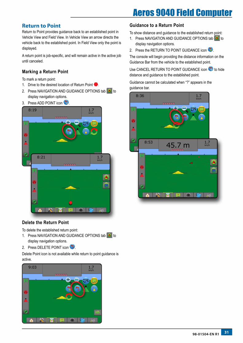
3198-01504-EN R1
Aeros 9040 Field ComputerReturn to PointReturn to Point provides guidance back to an established point in Vehicle View and Field View. In Vehicle View an arrow directs the vehicle back to the established point. In Field View only the point is displayed.
A return point is job-specific, and will remain active in the active job until canceled.
Marking a Return PointTo mark a return point:1. Drive to the desired location of Return Point .2. Press NAVIGATION AND GUIDANCE OPTIONS tab to
display navigation options.3. Press ADD POINT icon .
8:19
1.7 km/h
8:21
1.7 km/h
Delete the Return PointTo delete the established return point:1. Press NAVIGATION AND GUIDANCE OPTIONS tab to
display navigation options.2. Press DELETE POINT icon .Delete Point icon is not available while return to point guidance is active.
9:03
1.7 km/h
Guidance to a Return PointTo show distance and guidance to the established return point:1. Press NAVIGATION AND GUIDANCE OPTIONS tab to
display navigation options.2. Press the RETURN TO POINT GUIDANCE icon .The console will begin providing the distance information on the Guidance Bar from the vehicle to the established point.
Use CANCEL RETURN TO POINT GUIDANCE icon to hide distance and guidance to the established point.
Guidance cannot be calculated when “?” appears in the guidance bar.
8:36
1.7 km/h
8:53
1.7 km/h45.7 m
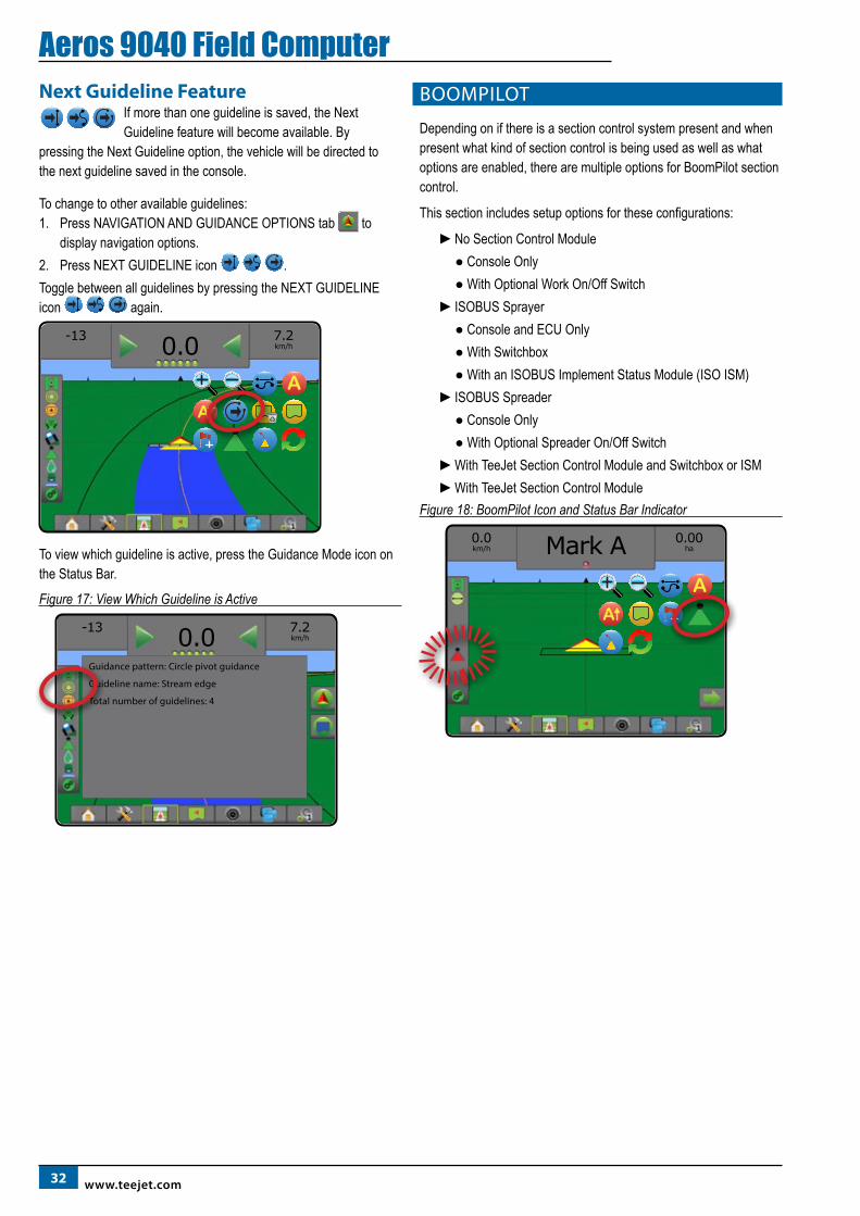
32 www.teejet.com
Aeros 9040 Field ComputerNext Guideline Feature
If more than one guideline is saved, the Next Guideline feature will become available. By
pressing the Next Guideline option, the vehicle will be directed to the next guideline saved in the console.
To change to other available guidelines:1. Press NAVIGATION AND GUIDANCE OPTIONS tab to
display navigation options.2. Press NEXT GUIDELINE icon .Toggle between all guidelines by pressing the NEXT GUIDELINE icon again.
-13
7.2km/h0.0
AA
To view which guideline is active, press the Guidance Mode icon on the Status Bar.
Figure 17: View Which Guideline is Active
-13
7.2km/h0.0
Guidance pattern: Circle pivot guidance
Guideline name: Stream edge
Total number of guidelines: 4
BOOMPILOT
Depending on if there is a section control system present and when present what kind of section control is being used as well as what options are enabled, there are multiple options for BoomPilot section control.
This section includes setup options for these configurations:
►No Section Control Module ● Console Only ● With Optional Work On/Off Switch►ISOBUS Sprayer ● Console and ECU Only ● With Switchbox ● With an ISOBUS Implement Status Module (ISO ISM)►ISOBUS Spreader ● Console Only ● With Optional Spreader On/Off Switch►With TeeJet Section Control Module and Switchbox or ISM►With TeeJet Section Control Module
Figure 18: BoomPilot Icon and Status Bar Indicator
0.0km/h
0.00haMark A
A
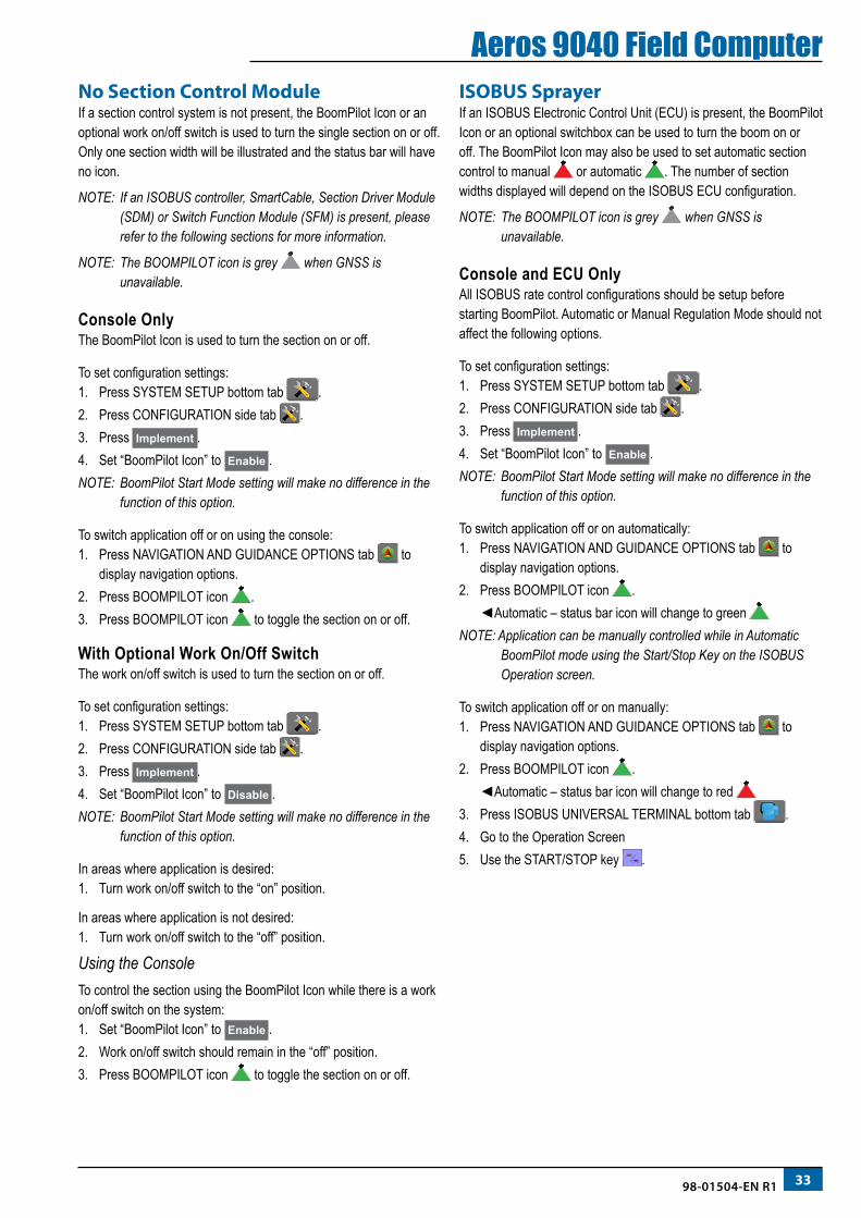
3398-01504-EN R1
Aeros 9040 Field ComputerNo Section Control ModuleIf a section control system is not present, the BoomPilot Icon or an optional work on/off switch is used to turn the single section on or off. Only one section width will be illustrated and the status bar will have no icon.
NOTE: If an ISOBUS controller, SmartCable, Section Driver Module (SDM) or Switch Function Module (SFM) is present, please refer to the following sections for more information.
NOTE: The BOOMPILOT icon is grey when GNSS is unavailable.
Console OnlyThe BoomPilot Icon is used to turn the section on or off.
To set configuration settings:1. Press SYSTEM SETUP bottom tab .2. Press CONFIGURATION side tab .3. Press Implement .4. Set “BoomPilot Icon” to Enable .NOTE: BoomPilot Start Mode setting will make no difference in the
function of this option.
To switch application off or on using the console:1. Press NAVIGATION AND GUIDANCE OPTIONS tab to
display navigation options.2. Press BOOMPILOT icon .3. Press BOOMPILOT icon to toggle the section on or off.
With Optional Work On/Off SwitchThe work on/off switch is used to turn the section on or off.
To set configuration settings:1. Press SYSTEM SETUP bottom tab .2. Press CONFIGURATION side tab .3. Press Implement .4. Set “BoomPilot Icon” to Disable .NOTE: BoomPilot Start Mode setting will make no difference in the
function of this option.
In areas where application is desired:1. Turn work on/off switch to the “on” position.
In areas where application is not desired:1. Turn work on/off switch to the “off” position.
Using the ConsoleTo control the section using the BoomPilot Icon while there is a work on/off switch on the system:1. Set “BoomPilot Icon” to Enable .2. Work on/off switch should remain in the “off” position.3. Press BOOMPILOT icon to toggle the section on or off.
ISOBUS SprayerIf an ISOBUS Electronic Control Unit (ECU) is present, the BoomPilot Icon or an optional switchbox can be used to turn the boom on or off. The BoomPilot Icon may also be used to set automatic section control to manual or automatic . The number of section widths displayed will depend on the ISOBUS ECU configuration.
NOTE: The BOOMPILOT icon is grey when GNSS is unavailable.
Console and ECU OnlyAll ISOBUS rate control configurations should be setup before starting BoomPilot. Automatic or Manual Regulation Mode should not affect the following options.
To set configuration settings:1. Press SYSTEM SETUP bottom tab .2. Press CONFIGURATION side tab .3. Press Implement .4. Set “BoomPilot Icon” to Enable .NOTE: BoomPilot Start Mode setting will make no difference in the
function of this option.
To switch application off or on automatically:1. Press NAVIGATION AND GUIDANCE OPTIONS tab to
display navigation options.2. Press BOOMPILOT icon .
◄Automatic – status bar icon will change to green NOTE: Application can be manually controlled while in Automatic
BoomPilot mode using the Start/Stop Key on the ISOBUS Operation screen.
To switch application off or on manually:1. Press NAVIGATION AND GUIDANCE OPTIONS tab to
display navigation options.2. Press BOOMPILOT icon .
◄Automatic – status bar icon will change to red 3. Press ISOBUS UNIVERSAL TERMINAL bottom tab .4. Go to the Operation Screen5. Use the START/STOP key .
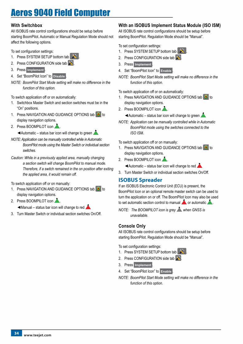
34 www.teejet.com
Aeros 9040 Field ComputerWith SwitchboxAll ISOBUS rate control configurations should be setup before starting BoomPilot. Automatic or Manual Regulation Mode should not affect the following options.
To set configuration settings:1. Press SYSTEM SETUP bottom tab .2. Press CONFIGURATION side tab .3. Press Implement .4. Set “BoomPilot Icon” to Disable .NOTE: BoomPilot Start Mode setting will make no difference in the
function of this option.
To switch application off or on automatically:1. Switchbox Master Switch and section switches must be in the
“On” positions. 1. Press NAVIGATION AND GUIDANCE OPTIONS tab to
display navigation options.2. Press BOOMPILOT icon .
◄Automatic – status bar icon will change to green NOTE: Application can be manually controlled while in Automatic
BoomPilot mode using the Master Switch or individual section switches.
Caution: While in a previously applied area, manually changing a section switch will change BoomPilot to manual mode. Therefore, if a switch remained in the on position after exiting the applied area, it would remain off.
To switch application off or on manually:1. Press NAVIGATION AND GUIDANCE OPTIONS tab to
display navigation options.2. Press BOOMPILOT icon .
◄Manual – status bar icon will change to red 3. Turn Master Switch or individual section switches On/Off.
With an ISOBUS Implement Status Module (ISO ISM)All ISOBUS rate control configurations should be setup before starting BoomPilot. Regulation Mode should be “Manual”.
To set configuration settings:1. Press SYSTEM SETUP bottom tab .2. Press CONFIGURATION side tab .3. Press Implement .4. Set “BoomPilot Icon” to Enable .NOTE: BoomPilot Start Mode setting will make no difference in the
function of this option.
To switch application off or on automatically:1. Press NAVIGATION AND GUIDANCE OPTIONS tab to
display navigation options.2. Press BOOMPILOT icon .
◄Automatic – status bar icon will change to green NOTE: Application can be manually controlled while in Automatic
BoomPilot mode using the switches connected to the ISO ISM.
To switch application off or on manually:1. Press NAVIGATION AND GUIDANCE OPTIONS tab to
display navigation options.2. Press BOOMPILOT icon .
◄Automatic – status bar icon will change to red 3. Turn Master Switch or individual section switches On/Off.
ISOBUS SpreaderIf an ISOBUS Electronic Control Unit (ECU) is present, the BoomPilot Icon or an optional remote master switch can be used to turn the application on or off. The BoomPilot Icon may also be used to set automatic section control to manual or automatic .
NOTE: The BOOMPILOT icon is grey when GNSS is unavailable.
Console OnlyAll ISOBUS rate control configurations should be setup before starting BoomPilot. Regulation Mode should be “Manual”.
To set configuration settings:1. Press SYSTEM SETUP bottom tab .2. Press CONFIGURATION side tab .3. Press Implement .4. Set “BoomPilot Icon” to Enable .NOTE: BoomPilot Start Mode setting will make no difference in the
function of this option.
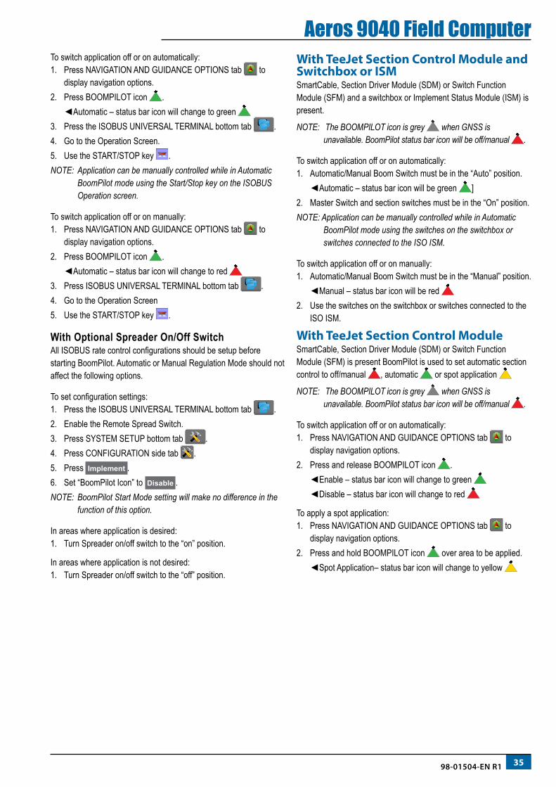
3598-01504-EN R1
Aeros 9040 Field ComputerTo switch application off or on automatically:1. Press NAVIGATION AND GUIDANCE OPTIONS tab to
display navigation options.2. Press BOOMPILOT icon .
◄Automatic – status bar icon will change to green 3. Press the ISOBUS UNIVERSAL TERMINAL bottom tab .4. Go to the Operation Screen.5. Use the START/STOP key .NOTE: Application can be manually controlled while in Automatic
BoomPilot mode using the Start/Stop key on the ISOBUS Operation screen.
To switch application off or on manually:1. Press NAVIGATION AND GUIDANCE OPTIONS tab to
display navigation options.2. Press BOOMPILOT icon .
◄Automatic – status bar icon will change to red 3. Press ISOBUS UNIVERSAL TERMINAL bottom tab .4. Go to the Operation Screen5. Use the START/STOP key .
With Optional Spreader On/Off SwitchAll ISOBUS rate control configurations should be setup before starting BoomPilot. Automatic or Manual Regulation Mode should not affect the following options.
To set configuration settings:1. Press the ISOBUS UNIVERSAL TERMINAL bottom tab .2. Enable the Remote Spread Switch.3. Press SYSTEM SETUP bottom tab .4. Press CONFIGURATION side tab .5. Press Implement .6. Set “BoomPilot Icon” to Disable .NOTE: BoomPilot Start Mode setting will make no difference in the
function of this option.
In areas where application is desired:1. Turn Spreader on/off switch to the “on” position.
In areas where application is not desired:1. Turn Spreader on/off switch to the “off” position.
With TeeJet Section Control Module and Switchbox or ISMSmartCable, Section Driver Module (SDM) or Switch Function Module (SFM) and a switchbox or Implement Status Module (ISM) is present.
NOTE: The BOOMPILOT icon is grey when GNSS is unavailable. BoomPilot status bar icon will be off/manual .
To switch application off or on automatically:1. Automatic/Manual Boom Switch must be in the “Auto” position.
◄Automatic – status bar icon will be green ]2. Master Switch and section switches must be in the “On” position.NOTE: Application can be manually controlled while in Automatic
BoomPilot mode using the switches on the switchbox or switches connected to the ISO ISM.
To switch application off or on manually:1. Automatic/Manual Boom Switch must be in the “Manual” position.
◄Manual – status bar icon will be red 2. Use the switches on the switchbox or switches connected to the
ISO ISM.
With TeeJet Section Control ModuleSmartCable, Section Driver Module (SDM) or Switch Function Module (SFM) is present BoomPilot is used to set automatic section control to off/manual , automatic or spot application
NOTE: The BOOMPILOT icon is grey when GNSS is unavailable. BoomPilot status bar icon will be off/manual .
To switch application off or on automatically:1. Press NAVIGATION AND GUIDANCE OPTIONS tab to
display navigation options.2. Press and release BOOMPILOT icon .
◄Enable – status bar icon will change to green ◄Disable – status bar icon will change to red
To apply a spot application:1. Press NAVIGATION AND GUIDANCE OPTIONS tab to
display navigation options.2. Press and hold BOOMPILOT icon over area to be applied.
◄Spot Application– status bar icon will change to yellow
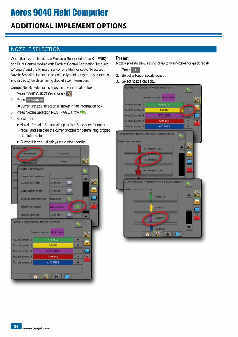
36 www.teejet.com
Aeros 9040 Field ComputerADDITIONAL IMPLEMENT OPTIONS
NOZZLE SELECTION
When the system includes a Pressure Sensor Interface Kit (PSIK), or a Dual Control Module with Product Control Application Type set to “Liquid” and the Primary Sensor or a Monitor set to “Pressure”, Nozzle Selection is used to select the type of sprayer nozzle (series and capacity) for determining droplet size information.
Current Nozzle selection is shown in the information box1. Press CONFIGURATION side tab .2. Press Implement .
◄Current Nozzle selection is shown in the information box3. Press Nozzle Selection NEXT PAGE arrow .4. Select from:
►Nozzle Preset 1-5 – selects up to five (5) nozzles for quick recall, and selected the current nozzle for determining droplet size information
►Current Nozzle – displays the current nozzle
PresetNozzle presets allow saving of up to five nozzles for quick recall.1. Press + .2. Select a TeeJet nozzle series.3. Select nozzle capacity.
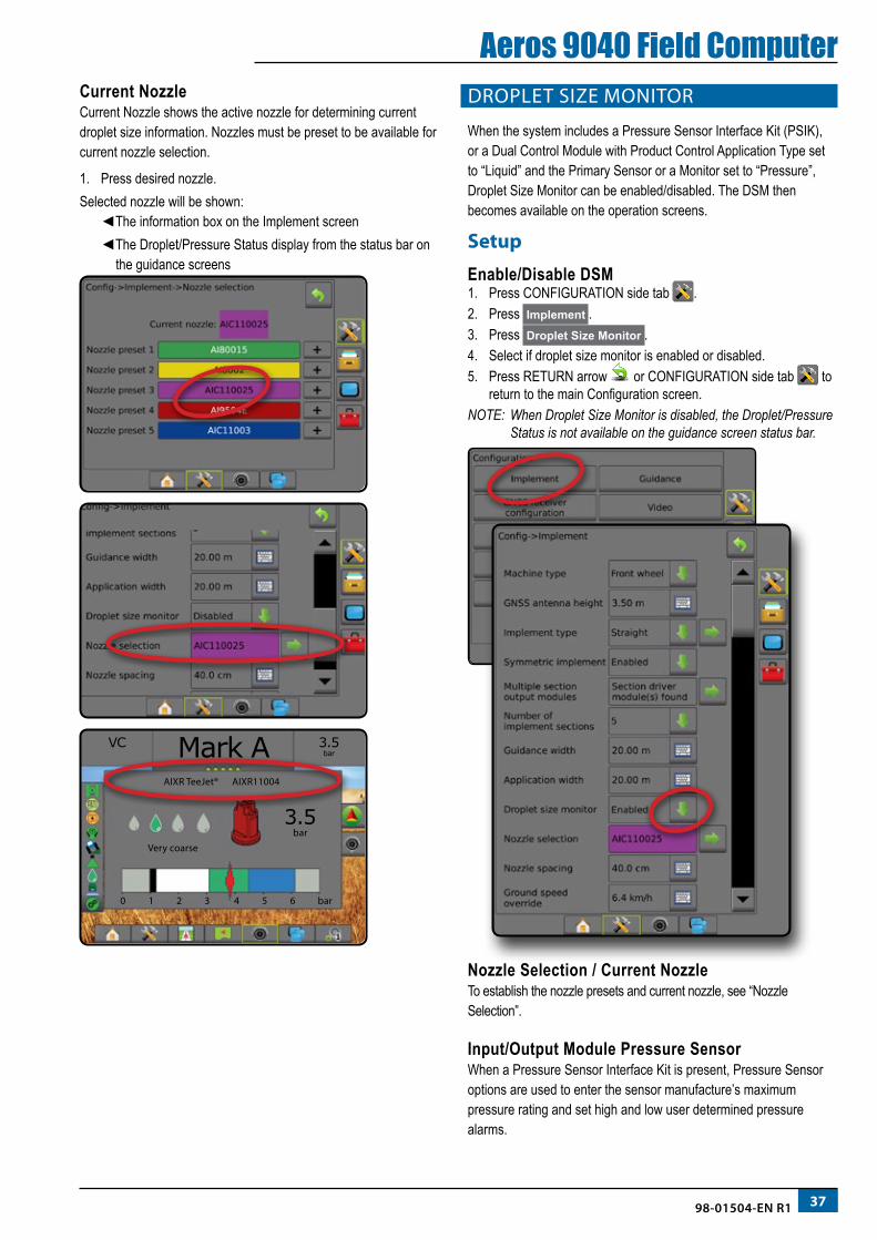
3798-01504-EN R1
Aeros 9040 Field ComputerCurrent NozzleCurrent Nozzle shows the active nozzle for determining current droplet size information. Nozzles must be preset to be available for current nozzle selection.
1. Press desired nozzle.Selected nozzle will be shown:
◄The information box on the Implement screen◄The Droplet/Pressure Status display from the status bar on
the guidance screens
VC
3.5barMark A
AIXR TeeJet® AIXR11004
Very coarse
0 1 2 3 4 5 6 bar
3.5bar
DROPLET SIZE MONITOR
When the system includes a Pressure Sensor Interface Kit (PSIK), or a Dual Control Module with Product Control Application Type set to “Liquid” and the Primary Sensor or a Monitor set to “Pressure”, Droplet Size Monitor can be enabled/disabled. The DSM then becomes available on the operation screens.
Setup
Enable/Disable DSM1. Press CONFIGURATION side tab .2. Press Implement .3. Press Droplet Size Monitor .4. Select if droplet size monitor is enabled or disabled.5. Press RETURN arrow or CONFIGURATION side tab to
return to the main Configuration screen.NOTE: When Droplet Size Monitor is disabled, the Droplet/Pressure
Status is not available on the guidance screen status bar.
Nozzle Selection / Current NozzleTo establish the nozzle presets and current nozzle, see “Nozzle Selection”.
Input/Output Module Pressure SensorWhen a Pressure Sensor Interface Kit is present, Pressure Sensor options are used to enter the sensor manufacture’s maximum pressure rating and set high and low user determined pressure alarms.
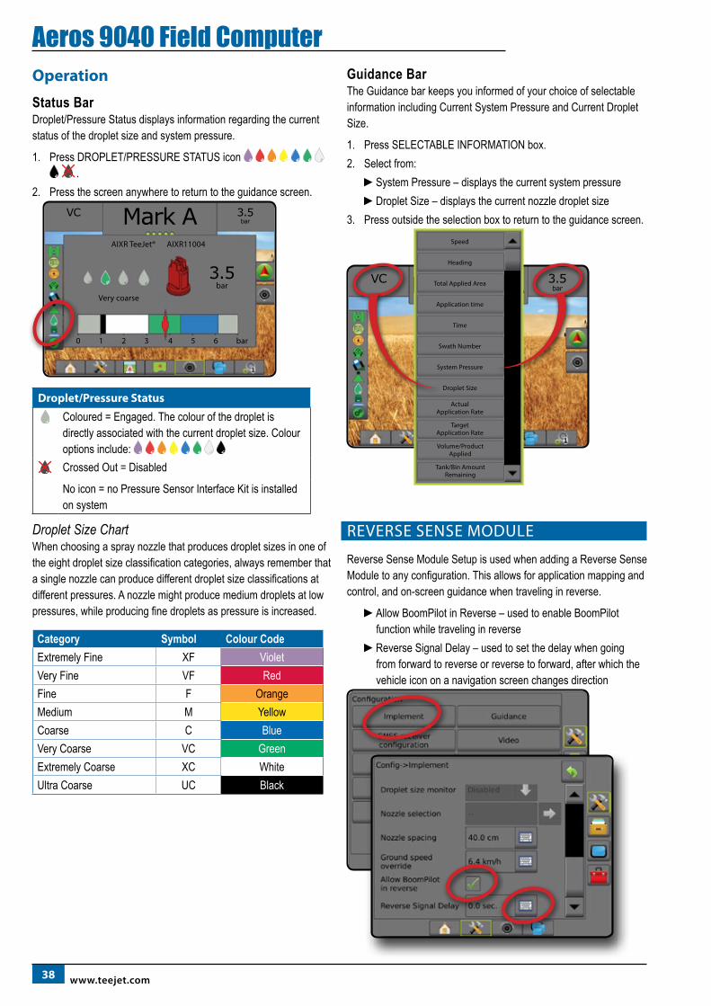
38 www.teejet.com
Aeros 9040 Field ComputerOperation
Status BarDroplet/Pressure Status displays information regarding the current status of the droplet size and system pressure.
1. Press DROPLET/PRESSURE STATUS icon .
2. Press the screen anywhere to return to the guidance screen.VC
3.5barMark A
AIXR TeeJet® AIXR11004
Very coarse
0 1 2 3 4 5 6 bar
3.5bar
Droplet/Pressure Status
Coloured = Engaged. The colour of the droplet is directly associated with the current droplet size. Colour options include: Crossed Out = Disabled
No icon = no Pressure Sensor Interface Kit is installed on system
Droplet Size ChartWhen choosing a spray nozzle that produces droplet sizes in one of the eight droplet size classification categories, always remember that a single nozzle can produce different droplet size classifications at different pressures. A nozzle might produce medium droplets at low pressures, while producing fine droplets as pressure is increased.
Category Symbol Colour CodeExtremely Fine XF VioletVery Fine VF RedFine F OrangeMedium M YellowCoarse C BlueVery Coarse VC GreenExtremely Coarse XC WhiteUltra Coarse UC Black
Guidance BarThe Guidance bar keeps you informed of your choice of selectable information including Current System Pressure and Current Droplet Size.
1. Press SELECTABLE INFORMATION box.2. Select from:
►System Pressure – displays the current system pressure►Droplet Size – displays the current nozzle droplet size
3. Press outside the selection box to return to the guidance screen.
3.5bar
VC Markiere A
Speed
Total Applied Area
Time
System Pressure
Actual Application Rate
Droplet Size
Target Application Rate
Heading
Application time
Swath Number
Volume/Product Applied
Tank/Bin Amount Remaining
REVERSE SENSE MODULE
Reverse Sense Module Setup is used when adding a Reverse Sense Module to any configuration. This allows for application mapping and control, and on-screen guidance when traveling in reverse.
►Allow BoomPilot in Reverse – used to enable BoomPilot function while traveling in reverse
►Reverse Signal Delay – used to set the delay when going from forward to reverse or reverse to forward, after which the vehicle icon on a navigation screen changes direction
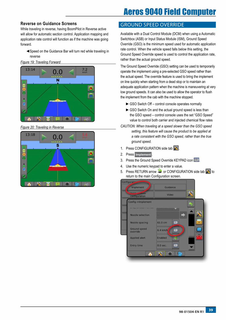
3998-01504-EN R1
Aeros 9040 Field ComputerReverse on Guidance ScreensWhile traveling in reverse, having BoomPilot in Reverse active will allow for automatic section control. Application mapping and application rate control will function as if the machine was going forward.
◄Speed on the Guidance Bar will turn red while traveling in reverse
Figure 19: Traveling Forward
13:14
7.2km/h0.0
Figure 20: Traveling in Reverse
13:18
5.6km/h0.0
GROUND SPEED OVERRIDE
Available with a Dual Control Module (DCM) when using a Automatic Switchbox (ASB) or Input Status Module (ISM), Ground Speed Override (GSO) is the minimum speed used for automatic application rate control. When the vehicle speed falls below this setting, the Ground Speed Override speed is used to control the application rate, rather than the actual ground speed.
The Ground Speed Override (GSO) setting can be used to temporarily operate the implement using a pre-selected GSO speed rather than the actual speed. The override feature is used to bring the implement on line quickly when starting from a dead stop or to maintain an adequate application pattern when the machine is maneuvering at very low ground speeds. It can also be used to allow the operator to flush the implement from the cab with the machine stopped.
►GSO Switch Off – control console operates normally►GSO Switch On and the actual ground speed is less than
the GSO speed – control console uses the set “GSO Speed” value to control both carrier and injected chemical flow rates
CAUTION: When traveling at a speed slower than the GSO speed setting, this feature will cause the product to be applied at a rate consistent with the GSO speed, rather than the true ground speed.
1. Press CONFIGURATION side tab .2. Press Implement .3. Press the Ground Speed Override KEYPAD icon . 4. Use the numeric keypad to enter a value. 5. Press RETURN arrow or CONFIGURATION side tab to
return to the main Configuration screen.
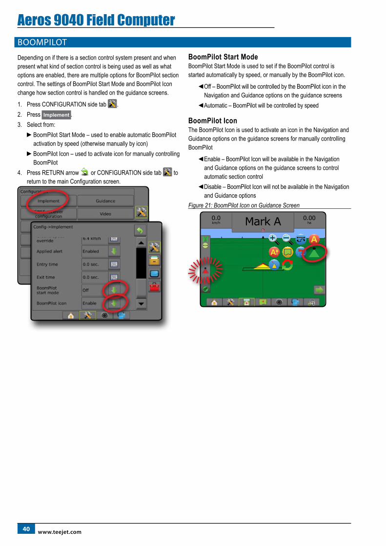
40 www.teejet.com
Aeros 9040 Field ComputerBOOMPILOT
Depending on if there is a section control system present and when present what kind of section control is being used as well as what options are enabled, there are multiple options for BoomPilot section control. The settings of BoomPilot Start Mode and BoomPilot Icon change how section control is handled on the guidance screens.
1. Press CONFIGURATION side tab .2. Press Implement .3. Select from:
►BoomPilot Start Mode – used to enable automatic BoomPilot activation by speed (otherwise manually by icon)
►BoomPilot Icon – used to activate icon for manually controlling BoomPilot
4. Press RETURN arrow or CONFIGURATION side tab to return to the main Configuration screen.
BoomPilot Start ModeBoomPilot Start Mode is used to set if the BoomPilot control is started automatically by speed, or manually by the BoomPilot icon.
◄Off – BoomPilot will be controlled by the BoomPilot icon in the Navigation and Guidance options on the guidance screens
◄Automatic – BoomPilot will be controlled by speed
BoomPilot IconThe BoomPilot Icon is used to activate an icon in the Navigation and Guidance options on the guidance screens for manually controlling BoomPilot
◄Enable – BoomPilot Icon will be available in the Navigation and Guidance options on the guidance screens to control automatic section control
◄Disable – BoomPilot Icon will not be available in the Navigation and Guidance options
Figure 21: BoomPilot Icon on Guidance Screen
0.0km/h
0.00haMark A
A
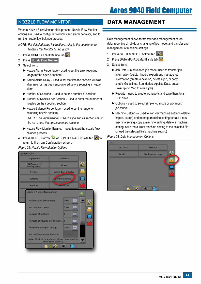
4198-01504-EN R1
Aeros 9040 Field ComputerNOZZLE FLOW MONITOR
When a Nozzle Flow Monitor Kit is present, Nozzle Flow Monitor options are used to configure flow limits and alarm behavior, and to run the nozzle flow balance process.
NOTE: For detailed setup instructions, refer to the supplemental Nozzle Flow Monitor (TFM) guide.
1. Press CONFIGURATION side tab .2. Press Nozzle Flow Monitor .3. Select from:
►Nozzle Alarm Percentage – used to set the error reporting range for the nozzle sensors
►Nozzle Alarm Delay – used to set the time the console will wait after an error has been encountered before sounding a nozzle alarm
►Number of Sections – used to set the number of sections►Number of Nozzles per Section – used to enter the number of
nozzles on the specified section►Nozzle Balance Percentage – used to set the range for
balancing nozzle sensors NOTE: The implement must be in a job and all sections must
be on to start the nozzle balance process.
►Nozzle Flow Monitor Balance – used to start the nozzle flow balance process
4. Press RETURN arrow or CONFIGURATION side tab to return to the main Configuration screen.
Figure 22: Nozzle Flow Monitor Options
DATA MANAGEMENT
Data Management allows for transfer and management of job data, reporting of job data, changing of job mode, and transfer and management of machine settings.
1. Press SYSTEM SETUP bottom tab .2. Press DATA MANAGEMENT side tab .3. Select from:
►Job Data – in advanced job mode, used to transfer job information (delete, import, export) and manage job information (create a new job, delete a job, or copy a job’s Guidelines, Boundaries, Applied Data, and/or Prescription Map to a new job)
►Reports – used to create job reports and save them to a USB drive
►Options – used to select simple job mode or advanced job mode
►Machine Settings – used to transfer machine settings (delete, import, export) and manage machine setting (create a new machine setting, copy a machine setting, delete a machine setting, save the current machine setting to the selected file, or load the selected file’s machine setting)
Figure 23: Data Management Options
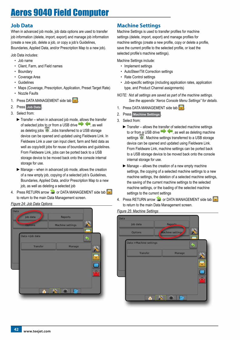
42 www.teejet.com
Aeros 9040 Field ComputerJob DataWhen in advanced job mode, job data options are used to transfer job information (delete, import, export) and manage job information (create a new job, delete a job, or copy a job’s Guidelines, Boundaries, Applied Data, and/or Prescription Map to a new job).
Job Data includes:• Job name• Client, Farm, and Field names• Boundary• Coverage Area• Guidelines• Maps (Coverage, Prescription, Application, Preset Target Rate)• Nozzle Faults
1. Press DATA MANAGEMENT side tab .2. Press Job Data .3. Select from:
►Transfer – when in advanced job mode, allows the transfer of selected jobs to or from a USB drive , as well as deleting jobs . Jobs transferred to a USB storage device can be opened and updated using Fieldware Link. In Fieldware Link a user can input client, farm and field data as well as copy/edit jobs for reuse of boundaries and guidelines. From Fieldware Link, jobs can be ported back to a USB storage device to be moved back onto the console internal storage for use.
►Manage – when in advanced job mode, allows the creation of a new empty job, copying of a selected job’s Guidelines, Boundaries, Applied Data, and/or Prescription Map to a new job, as well as deleting a selected job
4. Press RETURN arrow or DATA MANAGEMENT side tab to return to the main Data Management screen.
Figure 24: Job Data Options
Machine SettingsMachine Settings is used to transfer profiles for machine settings (delete, import, export) and manage profiles for machine settings (create a new profile, copy or delete a profile, save the current profile to the selected profile, or load the selected profile’s machine settings).
Machine Settings include:• Implement settings• AutoSteer/Tilt Correction settings• Rate Control settings• Job-specific settings (including application rates, application
type, and Product Channel assignments)
NOTE: Not all settings are saved as part of the machine settings. See the appendix “Aeros Console Menu Settings” for details.
1. Press DATA MANAGEMENT side tab .2. Press Machine Settings .3. Select from:
►Transfer – allows the transfer of selected machine settings to or from a USB drive , as well as deleting machine settings . Machine settings transferred to a USB storage device can be opened and updated using Fieldware Link. From Fieldware Link, machine settings can be ported back to a USB storage device to be moved back onto the console internal storage for use.
►Manage – allows the creation of a new empty machine settings, the copying of a selected machine settings to a new machine settings, the deletion of a selected machine settings, the saving of the current machine settings to the selected machine settings, or the loading of the selected machine settings to the current settings
4. Press RETURN arrow or DATA MANAGEMENT side tab to return to the main Data Management screen.
Figure 25: Machine Settings
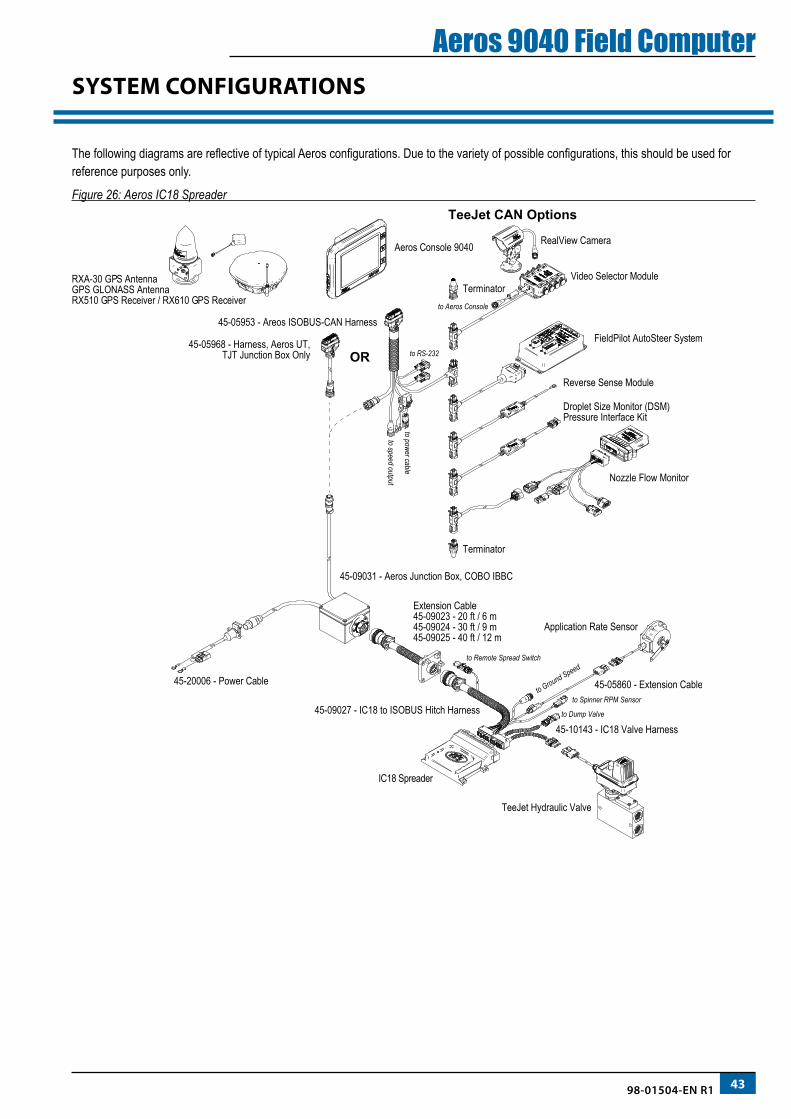
4398-01504-EN R1
Aeros 9040 Field ComputerSYSTEM CONFIGURATIONS
The following diagrams are reflective of typical Aeros configurations. Due to the variety of possible configurations, this should be used for reference purposes only.
Figure 26: Aeros IC18 Spreader
RXA-30 GPS Antenna GPS GLONASS AntennaRX510 GPS Receiver / RX610 GPS Receiver
Aeros Console 9040
45-05953 - Areos ISOBUS-CAN Harness
to power cable
to speed output
to RS-23245-05968 - Harness, Aeros UT,
TJT Junction Box Only OR
45-09031 - Aeros Junction Box, COBO IBBC
Extension Cable45-09023 - 20 ft / 6 m45-09024 - 30 ft / 9 m45-09025 - 40 ft / 12 m
to Ground Speed
to Spinner RPM Sensor
to Remote Spread Switch
to Dump Valve
45-20006 - Power Cable 45-05860 - Extension Cable
45-10143 - IC18 Valve Harness
IC18 Spreader
Application Rate Sensor
TeeJet Hydraulic Valve
45-09027 - IC18 to ISOBUS Hitch Harness
Video Selector Module
FieldPilot AutoSteer System
Reverse Sense Module
Terminator
Terminator
Nozzle Flow Monitor
Droplet Size Monitor (DSM)Pressure Interface Kit
RealView Camera
to Aeros Console
TeeJet CAN Options
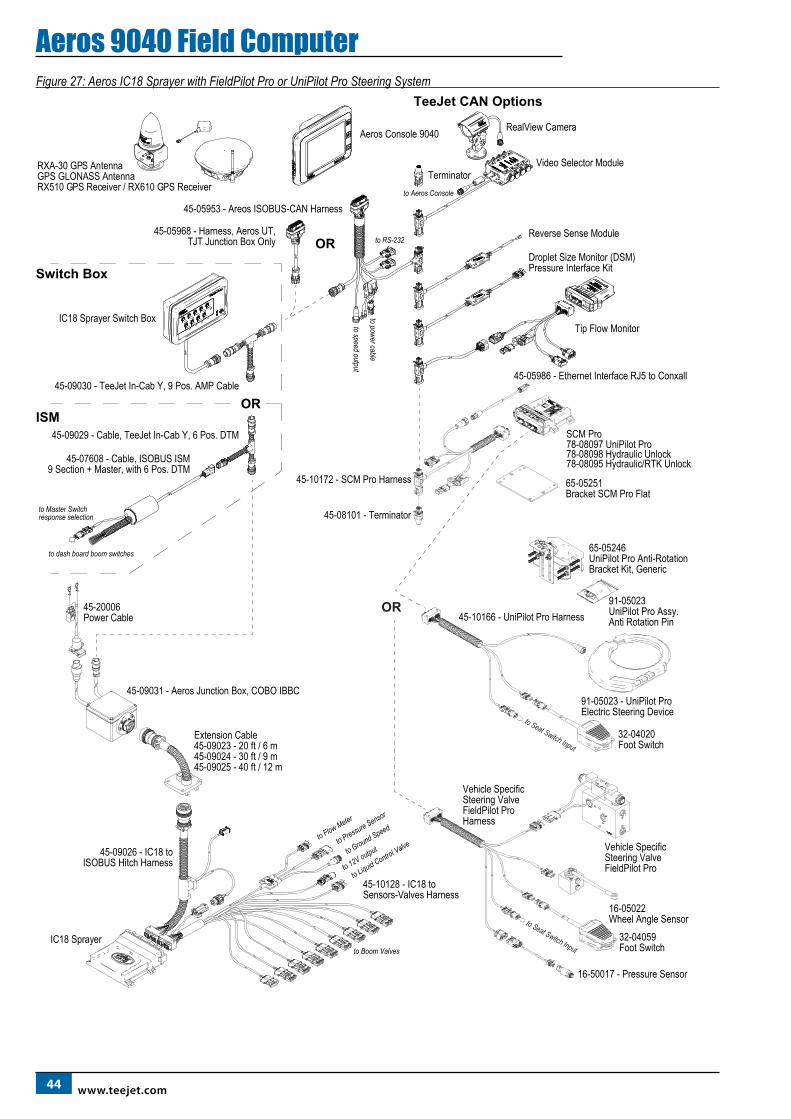
44 www.teejet.com
Aeros 9040 Field ComputerFigure 27: Aeros IC18 Sprayer with FieldPilot Pro or UniPilot Pro Steering System
RXA-30 GPS Antenna GPS GLONASS AntennaRX510 GPS Receiver / RX610 GPS Receiver
Aeros Console 9040
45-05953 - Areos ISOBUS-CAN Harness
to power cable
to speed output
to RS-23245-05968 - Harness, Aeros UT,
TJT Junction Box Only OR
IC18 Sprayer Switch Box
45-09030 - TeeJet In-Cab Y, 9 Pos. AMP Cable
45-09029 - Cable, TeeJet In-Cab Y, 6 Pos. DTM
45-07608 - Cable, ISOBUS ISM9 Section + Master, with 6 Pos. DTM
to dash board boom switches
to Master Switch response selection
OR
Switch Box
ISM
45-08101 - Terminator
45-10172 - SCM Pro Harness
SCM Pro78-08097 UniPilot Pro78-08098 Hydraulic Unlock78-08095 Hydraulic/RTK Unlock
65-05246UniPilot Pro Anti-Rotation Bracket Kit, Generic
45-05986 - Ethernet Interface RJ5 to Conxall
32-04020Foot Switch
45-10166 - UniPilot Pro Harness
91-05023 - UniPilot Pro Electric Steering Device
65-05251Bracket SCM Pro Flat
91-05023UniPilot Pro Assy.Anti Rotation Pin
OR
45-09031 - Aeros Junction Box, COBO IBBC
45-20006Power Cable
45-09026 - IC18 toISOBUS Hitch Harness
45-10128 - IC18 to Sensors-Valves Harness
IC18 Sprayer
Extension Cable45-09023 - 20 ft / 6 m45-09024 - 30 ft / 9 m45-09025 - 40 ft / 12 m
to Flow Meter
to Pressure Sensor
to Ground Speed
to 12V output
to Liquid Control Valve
to Boom Valves
to Seat Switch Input
to Seat Switch Input
Vehicle SpecificSteering ValveFieldPilot Pro Harness
Vehicle SpecificSteering ValveFieldPilot Pro
32-04059Foot Switch
16-05022Wheel Angle Sensor
16-50017 - Pressure Sensor
Video Selector Module
Reverse Sense Module
Terminator
Tip Flow Monitor
Droplet Size Monitor (DSM)Pressure Interface Kit
RealView Camera
to Aeros Console
TeeJet CAN Options
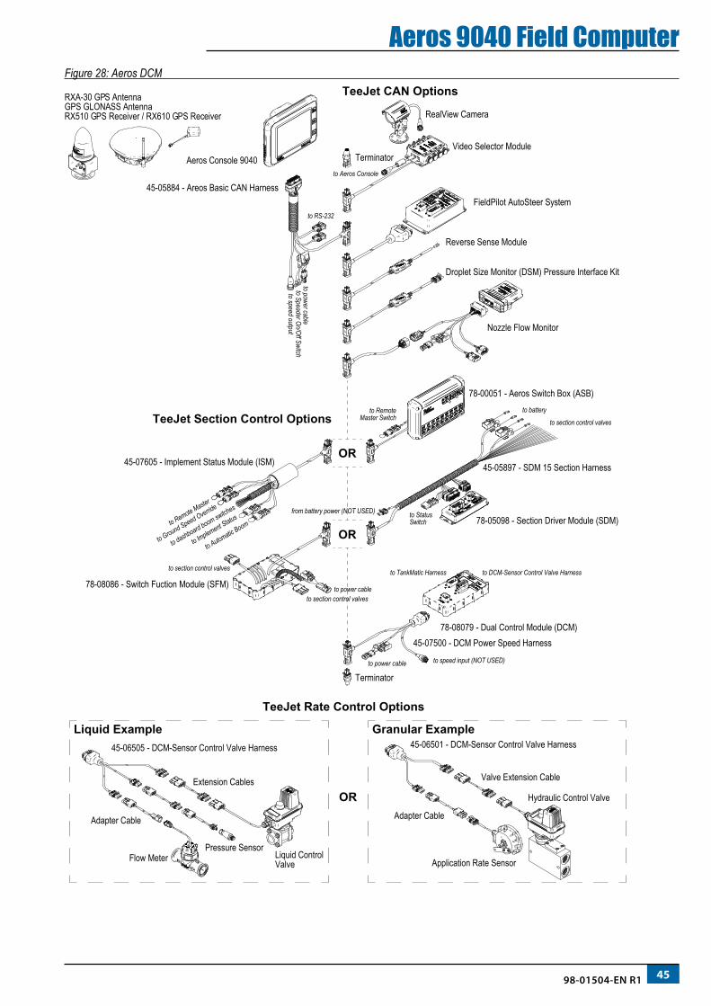
4598-01504-EN R1
Aeros 9040 Field ComputerFigure 28: Aeros DCM
RXA-30 GPS Antenna GPS GLONASS AntennaRX510 GPS Receiver / RX610 GPS Receiver
Aeros Console 9040
45-05884 - Areos Basic CAN Harness
to power cable
to power cable
to speed output
to RS-232
OR
OR
45-06505 - DCM-Sensor Control Valve Harness
Flow MeterPressure Sensor
Liquid ControlValve
Hydraulic Control Valve
Application Rate Sensor
45-06501 - DCM-Sensor Control Valve Harness
Valve Extension Cable Extension Cables
Adapter Cable Adapter Cable
Granular ExampleLiquid Example
OR
Video Selector Module
FieldPilot AutoSteer System
Reverse Sense Module
Terminator
Terminator
Nozzle Flow Monitor
Droplet Size Monitor (DSM) Pressure Interface Kit
RealView Camera
to Aeros Console
TeeJet CAN Options
TeeJet Rate Control Options
TeeJet Section Control Options
78-08079 - Dual Control Module (DCM)
78-00051 - Aeros Switch Box (ASB)
78-08086 - Switch Fuction Module (SFM)
45-07500 - DCM Power Speed Harness
to Speader On/Off Switch
45-07605 - Implement Status Module (ISM)
to dashboard boom switches
to Remote Master
to Ground Speed Override
to Implement Status
to Automatic Boomto StatusSwitch
to section control valves
to section control valvesto power cable
to RemoteMaster Switch
to DCM-Sensor Control Valve Harnessto TankMatic Harness
to speed input (NOT USED)
from battery power (NOT USED)
to section control valves
to battery
78-05098 - Section Driver Module (SDM)
45-05897 - SDM 15 Section Harness
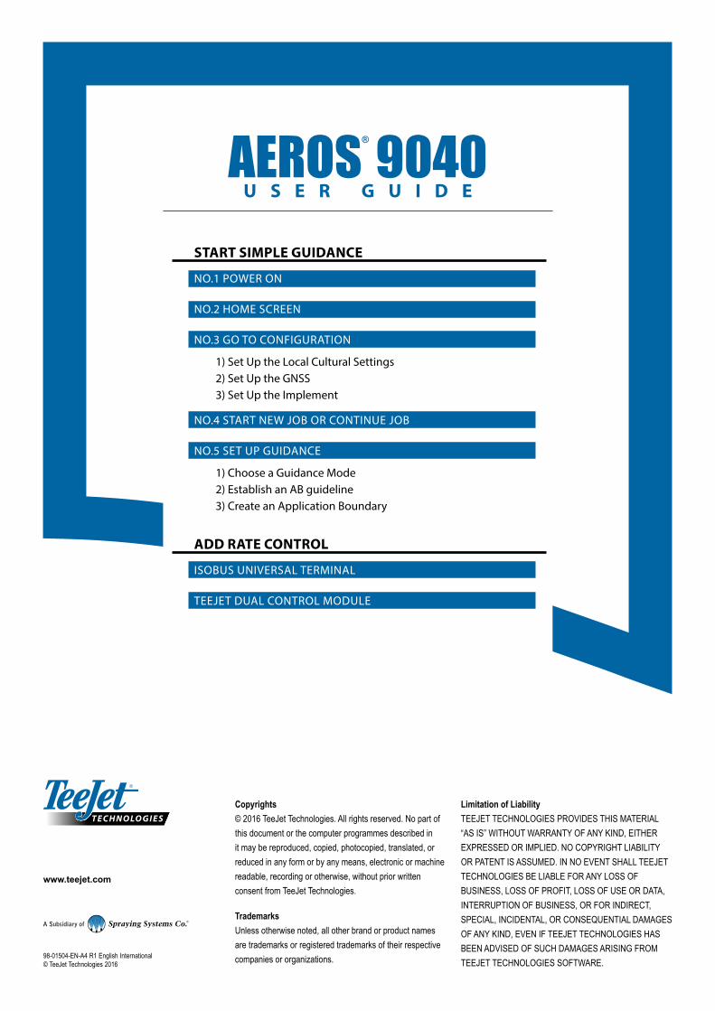
www.teejet.com
AEROS 9040U S E R G U I D E
98-01504-EN-A4 R1 English International © TeeJet Technologies 2016
Copyrights© 2016 TeeJet Technologies. All rights reserved. No part of this document or the computer programmes described in it may be reproduced, copied, photocopied, translated, or reduced in any form or by any means, electronic or machine readable, recording or otherwise, without prior written consent from TeeJet Technologies.
TrademarksUnless otherwise noted, all other brand or product names are trademarks or registered trademarks of their respective companies or organizations.
Limitation of LiabilityTEEJET TECHNOLOGIES PROVIDES THIS MATERIAL “AS IS” WITHOUT WARRANTY OF ANY KIND, EITHER EXPRESSED OR IMPLIED. NO COPYRIGHT LIABILITY OR PATENT IS ASSUMED. IN NO EVENT SHALL TEEJET TECHNOLOGIES BE LIABLE FOR ANY LOSS OF BUSINESS, LOSS OF PROFIT, LOSS OF USE OR DATA, INTERRUPTION OF BUSINESS, OR FOR INDIRECT, SPECIAL, INCIDENTAL, OR CONSEQUENTIAL DAMAGES OF ANY KIND, EVEN IF TEEJET TECHNOLOGIES HAS BEEN ADVISED OF SUCH DAMAGES ARISING FROM TEEJET TECHNOLOGIES SOFTWARE.
START SIMPLE GUIDANCE
NO.1 POWER ON
NO.2 HOME SCREEN
NO.3 GO TO CONFIGURATION
1) Set Up the Local Cultural Settings2) Set Up the GNSS3) Set Up the Implement
NO.4 START NEW JOB OR CONTINUE JOB
NO.5 SET UP GUIDANCE
1) Choose a Guidance Mode2) Establish an AB guideline3) Create an Application Boundary
ADD RATE CONTROL
ISOBUS UNIVERSAL TERMINAL
TEEJET DUAL CONTROL MODULE