Embed Size (px)
Citation preview


A.G.I.L.EAutonomously Guided Intelligent Lawn Equipment
Team Members:• Brad Ramsey
• Derek Rodriguez• Dane Wielgopolan
Project Advisors:• Dr. Joel Schipper• Dr. James Irwin

Who wants to mow the lawn?Who wants to pay someone else to mow the
lawn?
Why Build It?
Project Goal
Create a proof of concept autonomous lawnmower
• Mow the lawn while– Staying in a defined area– Avoiding obstacles– Efficient mowing
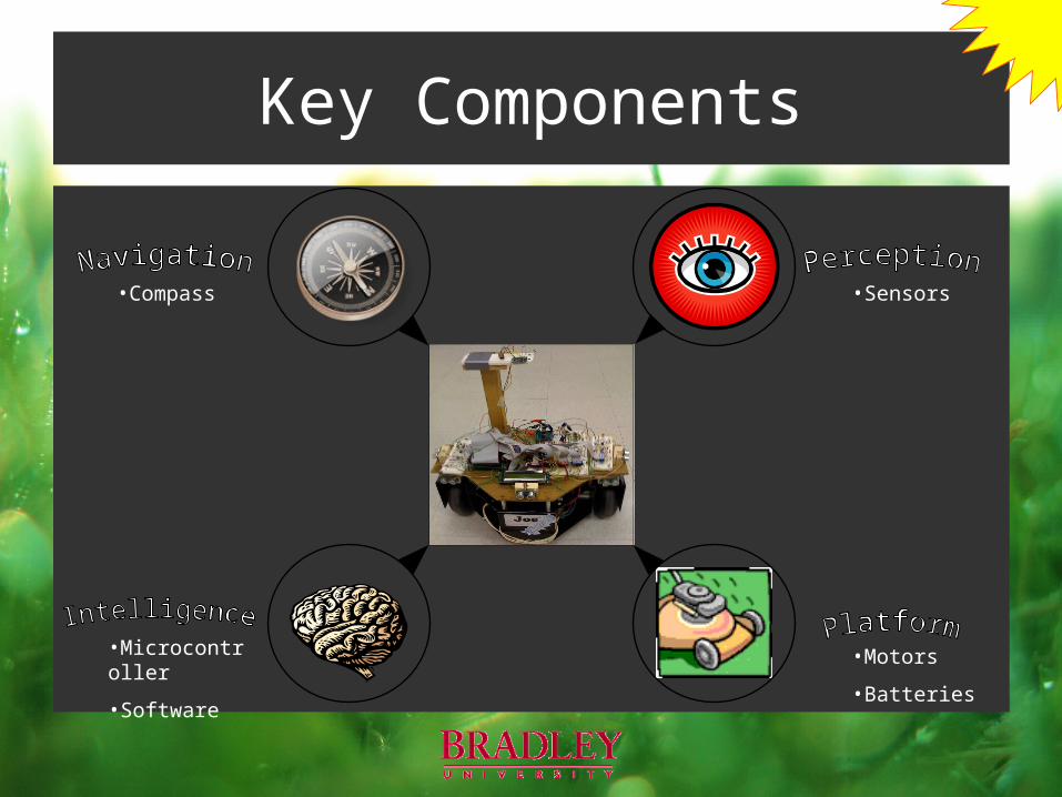
Key Components
A.G.I.L.E.
•Compass
•Microcontroller
•Software
•Sensors
•Motors
•Batteries

Key Components
A.G.I.L.E.
•Compass
•Microcontroller
•Software
•Sensors
•Motors
•Batteries
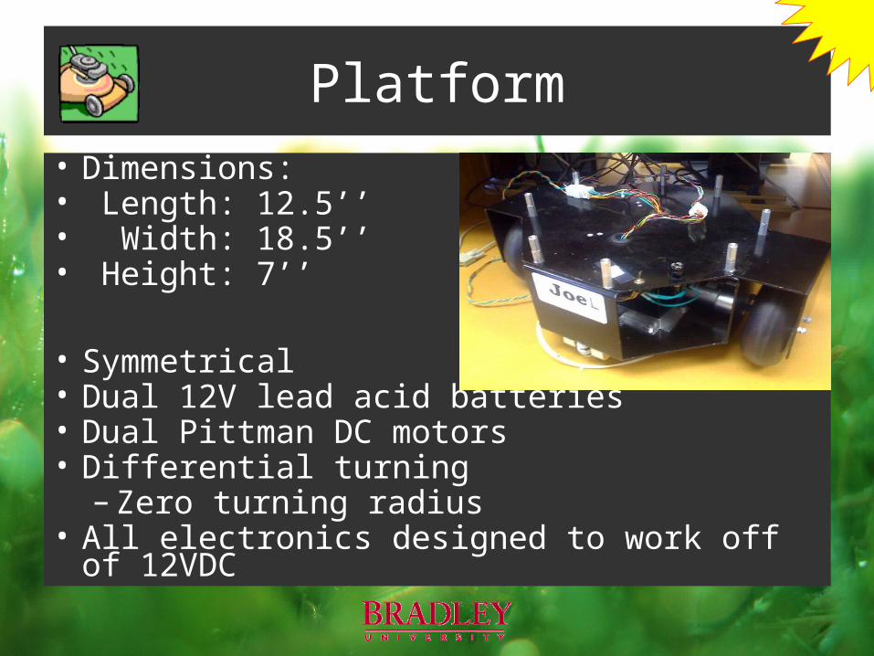
Platform• Dimensions:• Length: 12.5’’• Width: 18.5’’• Height: 7’’
• Symmetrical• Dual 12V lead acid batteries• Dual Pittman DC motors• Differential turning
– Zero turning radius• All electronics designed to work off of 12VDC
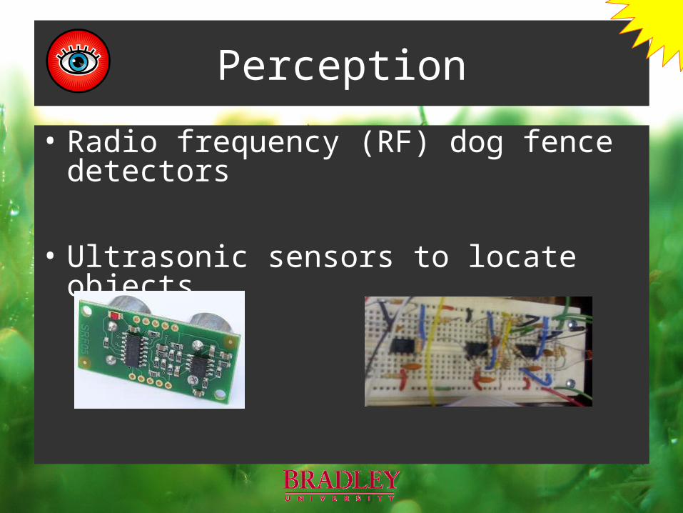
Perception
• Radio frequency (RF) dog fence detectors
• Ultrasonic sensors to locate objects
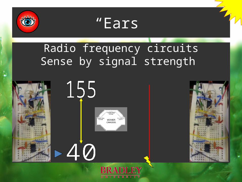
“Ears”
Radio frequency circuitsSense by signal strength
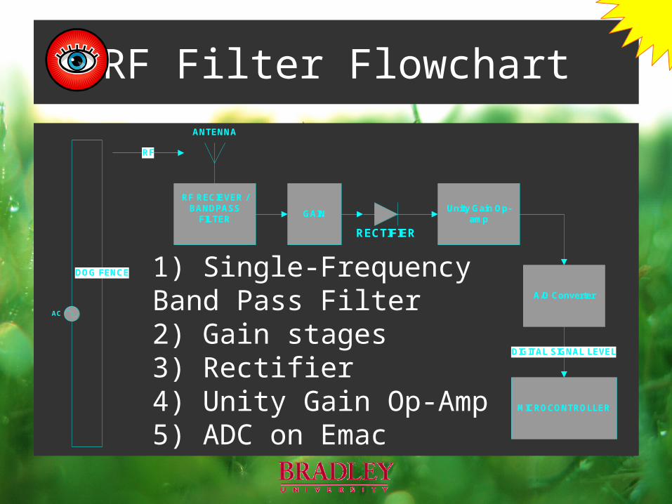
RF Filter Flowchart
RF RECIEVER / BANDPASS
FILTER
AC
RF
A/D Converter
MICROCONTROLLER
DIGITAL SIGNAL LEVEL
RECTIFIER
Unity Gain Op-amp
DOG FENCE
GAIN
ANTENNA
1) Single-Frequency Band Pass Filter2) Gain stages3) Rectifier4) Unity Gain Op-Amp 5) ADC on Emac
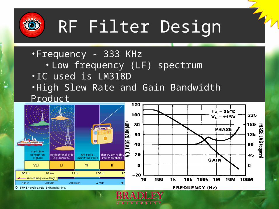
RF Filter Design•Frequency - 333 KHz
• Low frequency (LF) spectrum•IC used is LM318D•High Slew Rate and Gain Bandwidth Product
• Within desired noise floor
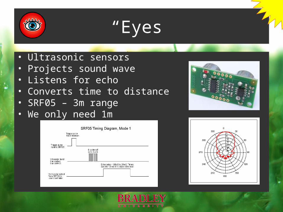
“Eyes”
• Ultrasonic sensors• Projects sound wave• Listens for echo• Converts time to distance• SRF05 – 3m range• We only need 1m
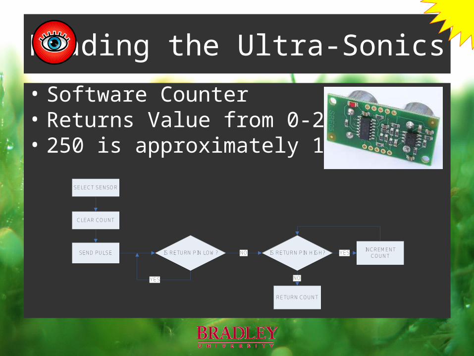
Reading the Ultra-Sonics
• Software Counter• Returns Value from 0-250• 250 is approximately 1m
CLEAR COUNT
SEND PULSE IS RETURN PIN LOW?
YES
IS RETURN PIN HIGH?NOINCREMENT
COUNTYES
RETURN COUNT
NO
SELECT SENSOR
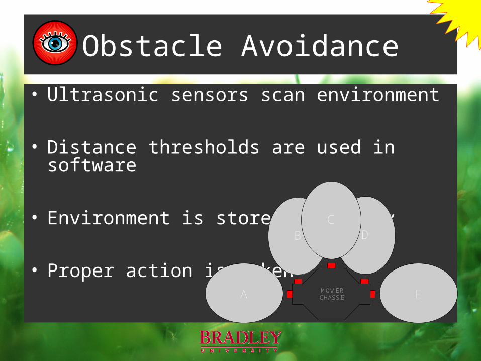
Obstacle Avoidance• Ultrasonic sensors scan environment
• Distance thresholds are used in software
• Environment is stored in memory
• Proper action is taken DB
MOWER CHASSIS
C
A E

Obstacle Avoidance
DB
MOWER CHASSIS
C
A E
DB
MOWER CHASSIS
C
A E
D
B
MO
WER
CH
ASSI
S
CA
E
D
B
MO
WER
CH
ASSI
S
CA
E

Key Components
A.G.I.L.E.
•Compass
•Microcontroller
•Software
•Sensors
•Motors
•Batteries
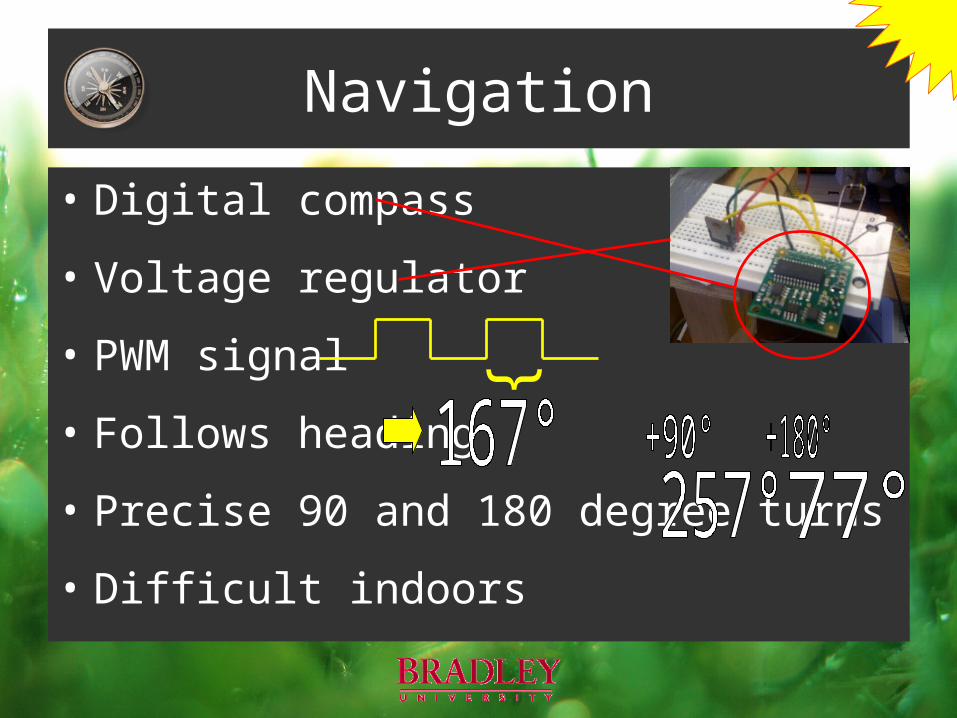
Navigation
• Digital compass
• Voltage regulator
• PWM signal
• Follows heading
• Precise 90 and 180 degree turns
• Difficult indoors
}
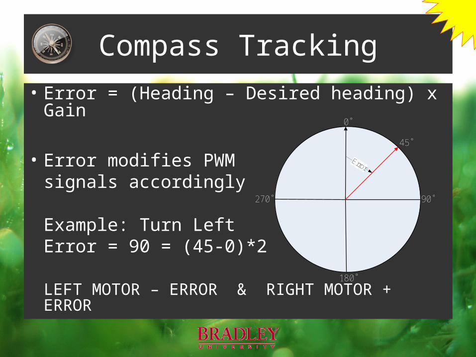
Compass Tracking
• Error = (Heading – Desired heading) x Gain
• Error modifies PWMsignals accordingly
Example: Turn LeftError = 90 = (45-0)*2
LEFT MOTOR – ERROR & RIGHT MOTOR + ERROR
0˚
90˚
180˚
270˚
45˚
Error
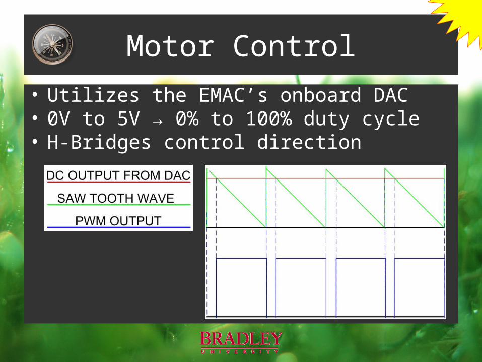
Motor Control• Utilizes the EMAC’s onboard DAC• 0V to 5V → 0% to 100% duty cycle• H-Bridges control direction

Key Components
A.G.I.L.E.
•Compass
•Microcontroller
•Software
•Sensors
•Motors
•Batteries
Intelligence
• Software uses sensors’ data
• Follow the border
• Cover the field twice
• Avoid static and dynamic obstacles
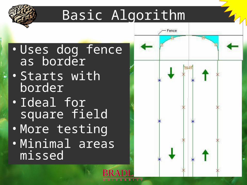
Basic Algorithm
• Uses dog fence as border
• Starts with border• Ideal for square field• More testing• Minimal areas
missed
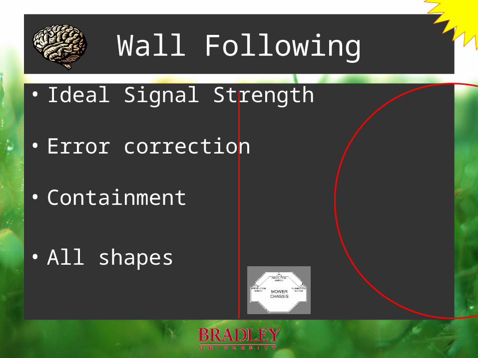
Wall Following
• Ideal Signal Strength
• Error correction
• Containment
• All shapes
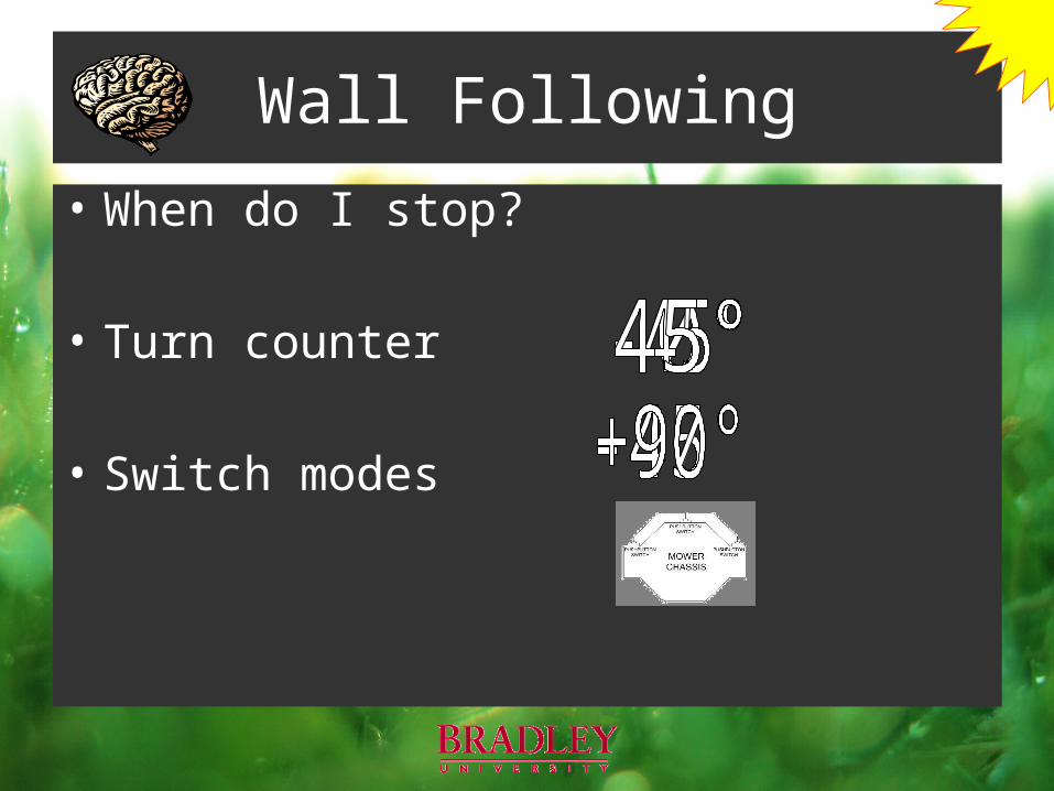
Wall Following
• When do I stop?
• Turn counter
• Switch modes
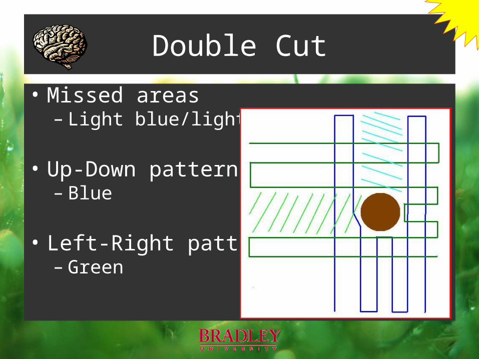
Double Cut
• Missed areas– Light blue/light green
• Up-Down pattern– Blue
• Left-Right pattern– Green
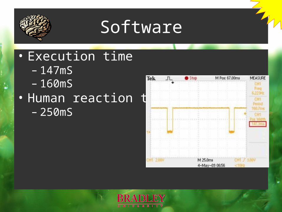
Software
• Execution time– 147mS – 160mS
• Human reaction time– 250mS
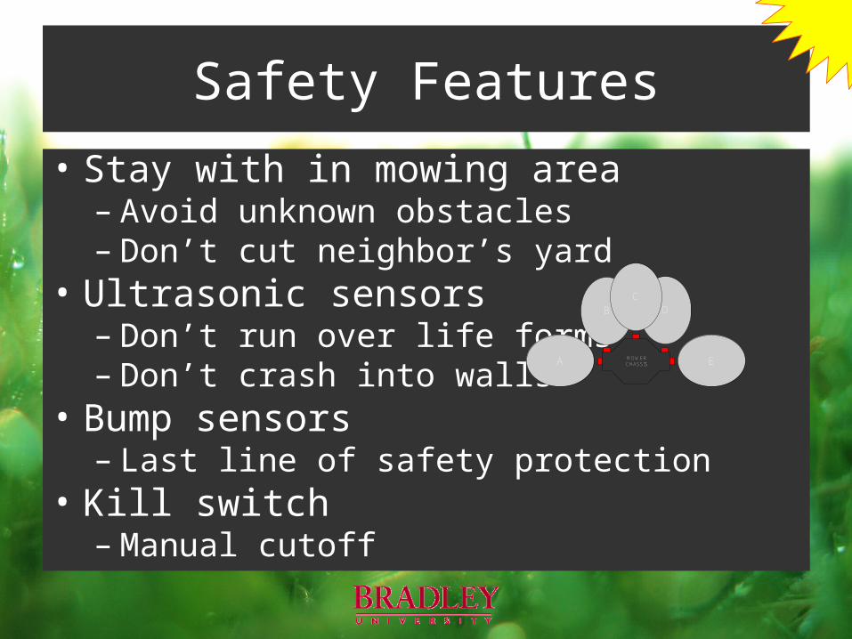
Safety Features
• Stay with in mowing area– Avoid unknown obstacles– Don’t cut neighbor’s yard
• Ultrasonic sensors– Don’t run over life forms– Don’t crash into walls
• Bump sensors– Last line of safety protection
• Kill switch– Manual cutoff
DB
MOWER CHASSIS
C
A E
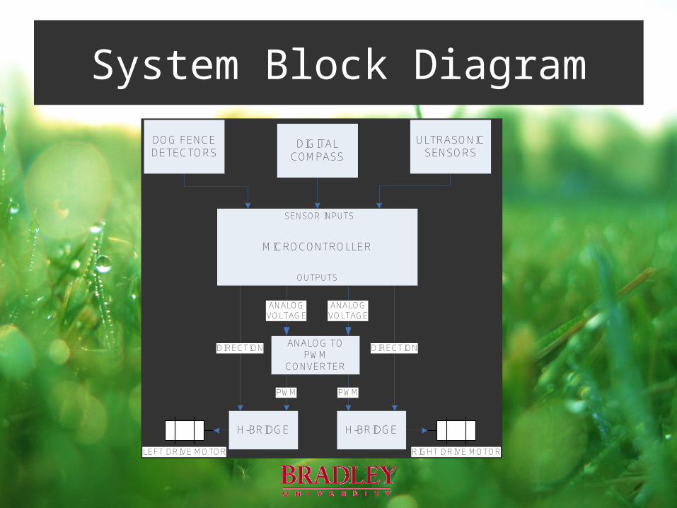
System Block Diagram
RIGHT DRIVE MOTORLEFT DRIVE MOTOR
DIRECTION DIRECTION
MICROCONTROLLER
SENSOR INPUTS
OUTPUTS
DIGITALCOMPASS
ULTRASONIC SENSORS
H-BRIDGE
PWM
H-BRIDGE
PWM
DOG FENCE DETECTORS
ANALOG TO PWM
CONVERTER
ANALOGVOLTAGE
ANALOG VOLTAGE
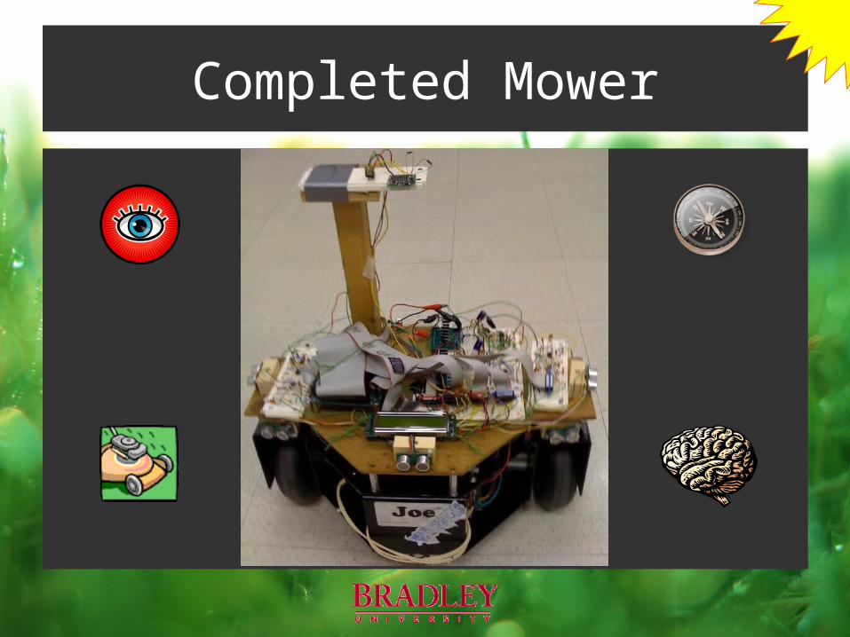
Completed Mower

Questions?
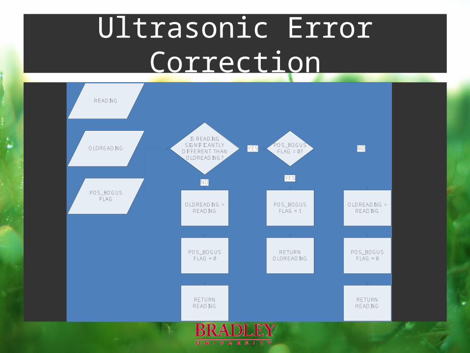
Ultrasonic Error Correction
IS READING SIGNIFICANTLY
DIFFERENT THAN OLDREADING?
YES
NO
READING
OLDREADING = READING
RETURN OLDREADING
OLDREADING
YES
POS_BOGUS FLAG = 0?
NO
POS_BOGUS FLAG
POS_BOGUS FLAG = 0
RETURN READING
POS_BOGUS FLAG = 1
OLDREADING = READING
POS_BOGUS FLAG = 0
RETURN READING
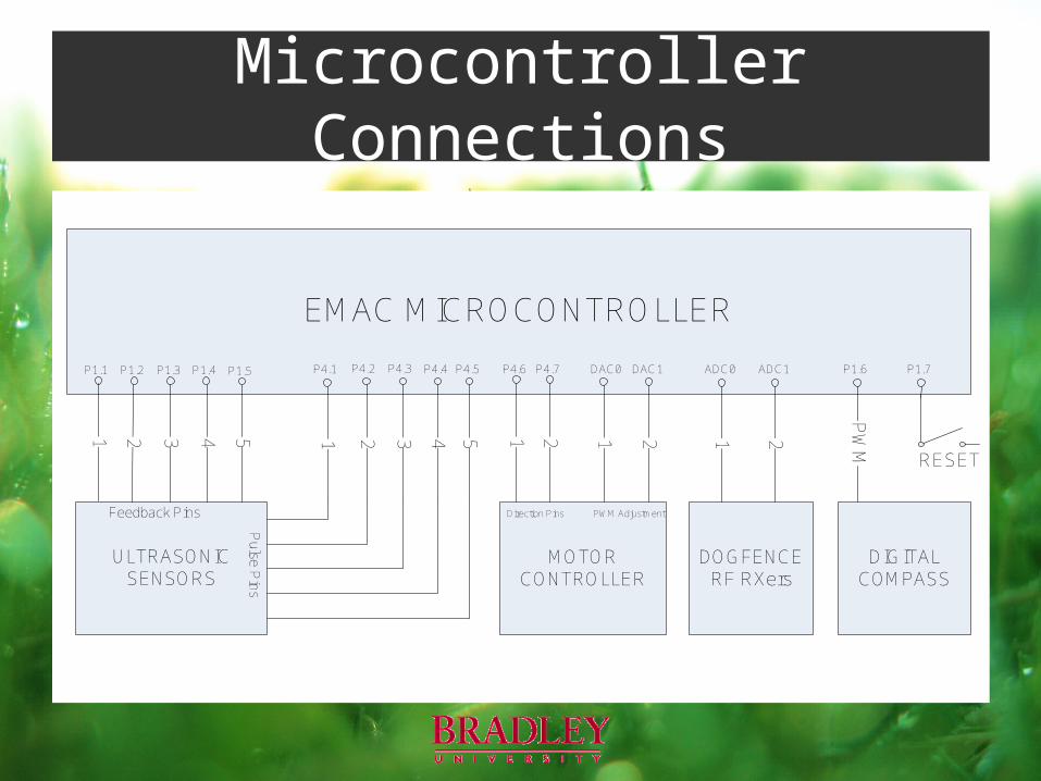
Microcontroller Connections
EMAC MICROCONTROLLER
ADC1ADC0P4.6 P4.7
DOGFENCERF RXers
MOTOR CONTROLLER
DAC0 DAC1
2121Direction Pins PWM Adjustment
DIGITALCOMPASS
P1.1 P1.2 P1.4 P4.1P1.3 P4.2 P4.3 P4.4
ULTRASONICSENSORS
2 31
Feedback Pins
Pulse P
ins
4 1 2 3 45
P1.5 P4.5
5 1 2
P1.6
PW
M
P1.7
RESET
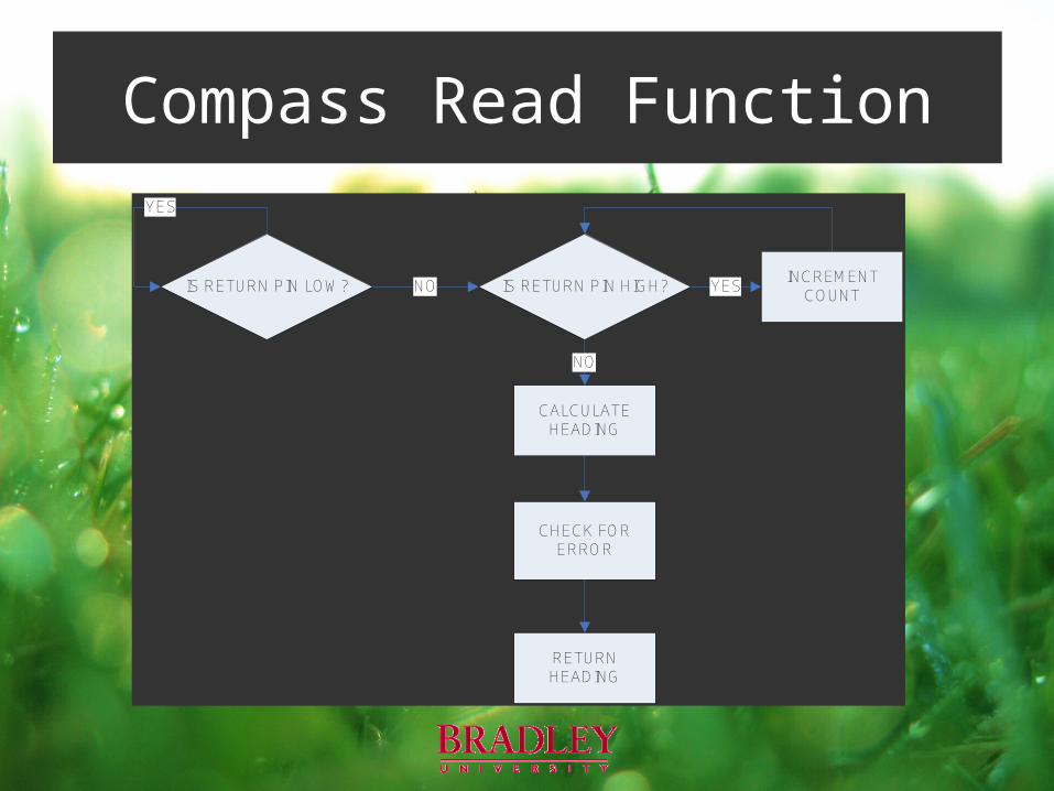
Compass Read Function
IS RETURN PIN LOW? IS RETURN PIN HIGH?NOINCREMENT
COUNTYES
CALCULATE HEADING
NO
YES
CHECK FOR ERROR
RETURN HEADING
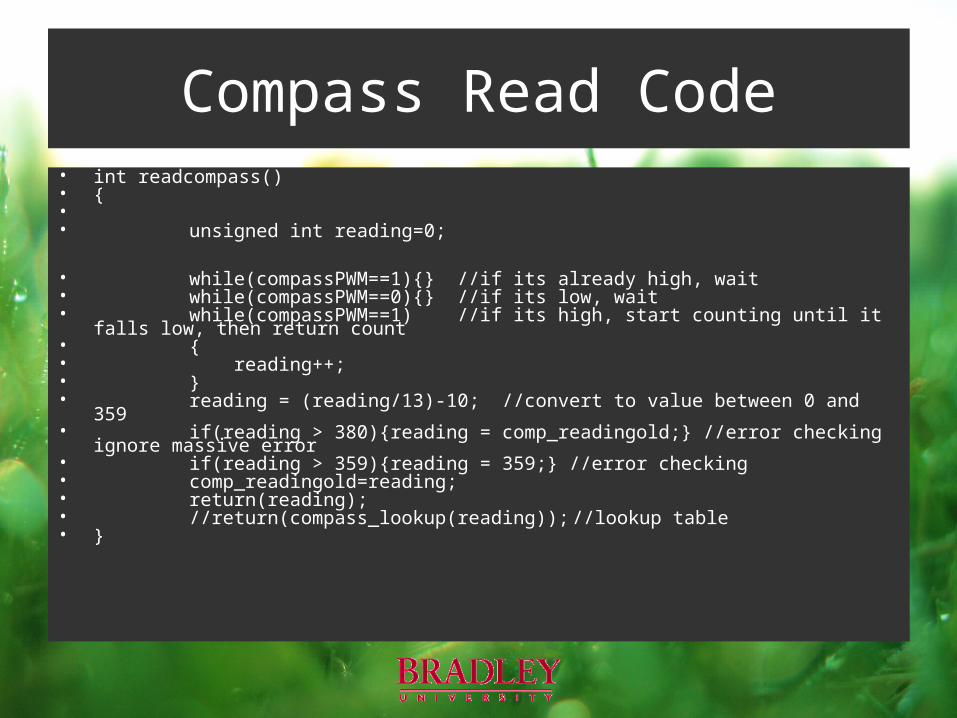
Compass Read Code• int readcompass()• {•• unsigned int reading=0;
• while(compassPWM==1){} //if its already high, wait• while(compassPWM==0){} //if its low, wait• while(compassPWM==1) //if its high, start counting until it falls low, then return count• {• reading++;• }• reading = (reading/13)-10; //convert to value between 0 and 359• if(reading > 380){reading = comp_readingold;} //error checking ignore massive error • if(reading > 359){reading = 359;} //error checking• comp_readingold=reading;• return(reading);• //return(compass_lookup(reading)); //lookup table• }
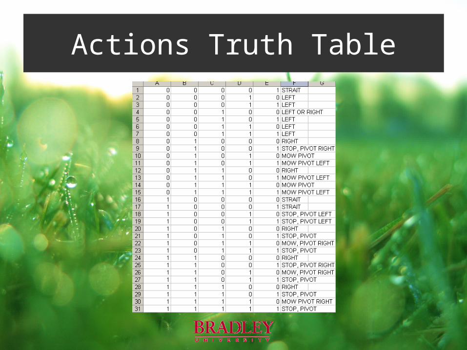
Actions Truth Table
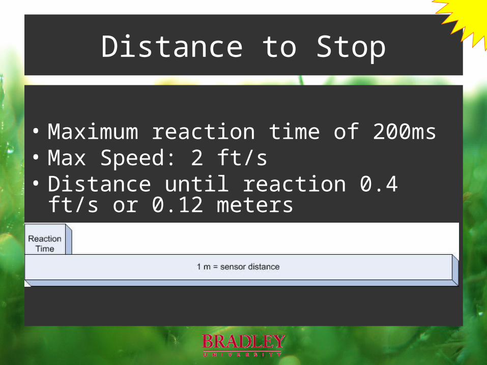
• Maximum reaction time of 200ms• Max Speed: 2 ft/s• Distance until reaction 0.4 ft/s or 0.12 meters
Distance to Stop