Embed Size (px)
Citation preview
Department of Industrial and Materials Science CHALMERS UNIVERSITY OF TECHNOLOGY Gothenburg, Sweden 2017
Agile Development of Automated Driving System A study on process and technology Master’s thesis in Product Development Paul Lazar Vishnu Shyam

Agile Development of Automated Driving System
A Study on Process and Technology
PAUL LAZAR VISHNU SHYAM
Department of Industrial and Materials Science Division of Product Development
CHALMERS UNIVERSITY OF TECHNOLOGY Gothenburg, Sweden 2017
Agile Development of Automated Driving System A Study on Process and Technology PAUL LAZAR VISHNU SHYAM © Paul Lazar, Vishnu Shyam, 2017 Examiner: Erik Hulthén, Department of Industrial and Materials Science, Chalmers University of Technology Department of Industrial and Materials Science Division of Product Development Chalmers University of Technology SE-412 96 Gothenburg Sweden Telephone +46 (0)31 772 1000 Gothenburg, Sweden 2017

This thesis report is part of a series of four theses resulting from a project which lasted from January to June 2017. The project was conducted by students from Chalmers University of Technology and carried out in Sigma Technology Development, in Gothenburg, Sweden. The other three theses in this series are:
1. “A model based approach to lane detection and lane positioning using OpenCV” by Daniel Posch and Jesper Rask
2. “Combining Deep Learning with traditional algorithms in autonomous cars” by Albin Falk and David Granqvist
3. “Controllers and their implementation for an autonomous vehicle” by Andreas Jakobsson and Anders Sundkvist

Abstract Vehicles equipped with autonomous driving functions are gaining wide popularity in the market, with several automotive and technology companies developing products in this area. An automated driving system can potentially have a strong economic and societal impact and can radically change the way that people use vehicles and transport in general. The effects can be seen in the current market; technology trends and legislation are all preparing for a large-scale commercialisation of automated driving systems. This thesis sets out to understand the product development process involved in developing an automated driving system and the technology choices that would be needed in developing such a system. This thesis investigates how a multidisciplinary team of students approached the development of an automated driving system on a scaled remote control vehicle. A lean product development process within an agile (Scrum) framework was employed as the process of development. Several technologies were investigated and evaluated for an effective technical solution. This process resulted in a scaled prototype that achieved some automated driving functionality in the considered conditions, by utilizing a camera system along with machine learning. The development process involved changes to the traditional Scrum methodology and standard product development process to enable combined hardware and software development. This resulting method aims to overcome the lack of communication between hardware and software teams and accommodate the difference in pace and dependencies that was observed between the two disciplines. Keywords: automated driving, autonomous, self-driving, development process, agile, lean, multidisciplinary


Acknowledgements We would like to extend a special thank you to Erik Hulthén for supervising and guiding us through this thesis and always giving us great feedback. We would also like to thank Alixander Ansari, our company supervisor, for giving us the opportunity to be a part of a project in an industry setting and with high industry relevance. His support and freedom with the project’s direction was greatly appreciated. We would also like to thank our team members Jesper Rask, David Granqvist, Daniel Posch, Albin Falk, Andreas Jakobsson and Anders Sundkvist for helping us co-develop and generate ideas with us. Without their hard work, the team would not have realised the prototype, nor would we have had a great deal of fun in the office. We would also like to thank everyone at Sigma Technology for providing an open and welcoming environment for us to work in. Finally, we would like to thank all our friends and colleagues who have participated in the focus group and contributed to a very interesting discussion.

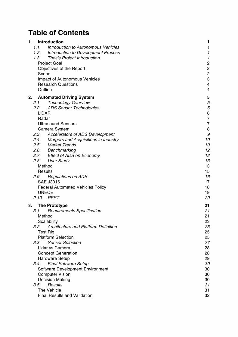
Table of Contents 1. Introduction 1
1.1. Introduction to Autonomous Vehicles 1 1.2. Introduction to Development Process 1 1.3. Thesis Project Introduction 1
Project Goal 2 Objectives of the Report 2 Scope 2 Impact of Autonomous Vehicles 3 Research Questions 4 Outline 4
2. Automated Driving System 5 2.1. Technology Overview 5 2.2. ADS Sensor Technologies 5
LiDAR 6 Radar 7 Ultrasound Sensors 7 Camera System 8
2.3. Accelerators of ADS Development 9 2.4. Mergers and Acquisitions in Industry 10 2.5. Market Trends 10 2.6. Benchmarking 12 2.7. Effect of ADS on Economy 12 2.8. User Study 13
Method 13 Results 15
2.9. Regulations on ADS 16 SAE J3016 17 Federal Automated Vehicles Policy 18 UNECE 19
2.10. PEST 20 3. The Prototype 21
3.1. Requirements Specification 21 Method 21 Scalability 23
3.2. Architecture and Platform Definition 25 Test Rig 25 Platform Selection 25
3.3. Sensor Selection 27 Lidar vs Camera 28 Concept Generation 28 Hardware Setup 29
3.4. Final Software Setup 30 Software Development Environment 30 Computer Vision 30 Decision Making 30
3.5. Results 31 The Vehicle 31 Final Results and Validation 32

4. Development Process 33
4.1. Lean and Agile Product Development 33 Traditional Product Development Process 33 Agile and Lean Product Development in Theory 34 Product Development Process Implemented 35 Scrum Framework Method 36 Implementation of Scrum 38 Results from Scrum Implementation 42 Project Management and Timeline 43
5. Discussion & Future work 45 5.1. Discussion 45 5.2. Future work 48
6. Conclusion 49 7. References 51 Appendix A – Requirements List 1/3 56 Appendix A – Requirements List 2/3 57 Appendix A – Requirements List 3/3 58 Appendix B – Benchmarking List 59 Appendix C – User Study Quotes 60 Appendix D – Scrum Retrospect 61 Appendix E – Technology Evaluation 62 Appendix F – Initial Project Planning with Gantt Chart 63
List of Abbreviations and Definitions ADS – Automated Driving System. Used to describe any system capable of Levels 3-4-5, according to SAE J3016 AI – Artificial Intelligence CAD – Computer Aided Design CPU – Central Processing Unit DDT – Dynamic Driving Task Driving automation system. Refers to any level 1-5 system, according to SAE J3016 FOV – Field of View (referring to sensors, such as cameras) GPU – Graphics Processing Unit Highly automated vehicle. Term used by the National Highway Traffic Safety Administration when referring to SAE Levels 3 to 5 of driving automation (NHTSA) IoT – Internet of Things MT – Mechatronics ODD – Operational Design Domain OEDR – Object and Event Detection and Response PD – Product Development RC – Remote Control SW – Software

1
1. Introduction 1.1. Introduction to Autonomous Vehicles
Autonomous vehicles are seeing significant technological advancements in the automotive field with a lot of research being carried out and several production ready models equipped with some automated driving functions. These in-vehicle systems range from driver assistance to semi-autonomous systems which often need little human input under certain operating conditions. While still in their infancy, autonomous driving systems could meet the modern-day customer’s needs for safety, efficiency and convenience, while also accelerating the shift towards a sustainable transport in the future. These driving systems are usually composed of several types of sensors that capture information from the environment, process it through powerful computers and take decisions to ultimately control the steering and propulsion of the car. Smart vehicles with autonomous functions furthermore enable use by multiple users.
1.2. Introduction to Development Process Product development processes describe a sequence of steps or activities undertaken by an enterprise to conceive, design and commercialise a product (Ulrich & Eppinger, 2012). Technological advancements and the appearance of connected systems, powerful computers, artificial intelligence etc. have brought about a new era for products, one in which physical products are a smart, complex system, embodying knowledge from many different engineering disciplines. To meet ever increasing demands for speed, efficiency and quality, new processes like Lean Product Development, as well as new approaches to software development (Williams, 2012) like Agile principles, have been adopted by companies to respond to a demanding market. Development teams are furthermore increasingly more diverse, with multidisciplinary staffing.
1.3. Thesis Project Introduction This thesis project regards the development of an Automated Driving System (ADS), initiated as a knowledge building exercise by Sigma Technology, a technology consultancy company based in Sweden. A subsidiary of the Sigma group, Sigma Technology has over 20 years of experience in providing consultancy services within the fields of embedded and software design, product information and information development, as well as information and content management systems for various industries (Sigma, 2017). The ADS was implemented on a 1:10 scale remote control vehicle due to the high costs required to develop and test an ADS on a full-scale automobile. The company which commissioned this project requested that the system be developed on an inexpensive remote control vehicle, while the appropriate requirements could still be fulfilled when scaled up to an automobile. The work carried out by the authors of this report is part of a larger, multi-disciplinary team of eight students. The four thesis reports resulting from this project have different focus areas. The students involved in the project are of diverse academic backgrounds, with members studying computer science, mechatronics and product development. The thesis authors are responsible for the overall project direction with focus on the overall system requirements. The thesis authors are also responsible for ensuring proper integration of the various subsystems, by ensuring cross-functional coordination of the different stakeholders, along with assistance in - and documentation of - major technical decisions taken based on methodology, all with the goal of achieving an optimal system level solution.
2
Project Goal The goal of this project is to build a highly Automated Driving System on a 1:10 scaled vehicle within the span of five months, capable of navigating a course representative of the real road environment. The vehicle therefore would need to read the road markings, interpret traffic signs and take appropriate action to manoeuvre and obey traffic rules. The vehicle furthermore needs to be able to detect and respond to objects in the environment. The system would be developed considering scalability to real-world dimensions. Additionally, the system would enable manual control over the vehicle. The 1:10 scale vehicle is meant to represent and showcase the company’s technology and competence in the field of autonomous drive at fairs and company events.
Objectives of the Report The main objective of this thesis report as a whole is the exploration of agile product development practices in an ADS development project, staffed by a multidisciplinary team of eight students, simulating industry conditions. Furthermore, this thesis report aims to build knowledge in the area of autonomous vehicle development by exploring the various technologies capable of achieving automated driving, along with relevant market and regulations information. The authors’ main deliverable to the company is to establish the basic prerequisites needed to achieve driving automation similar to that of existing autonomous-featured vehicles on the market, with minimal hardware.
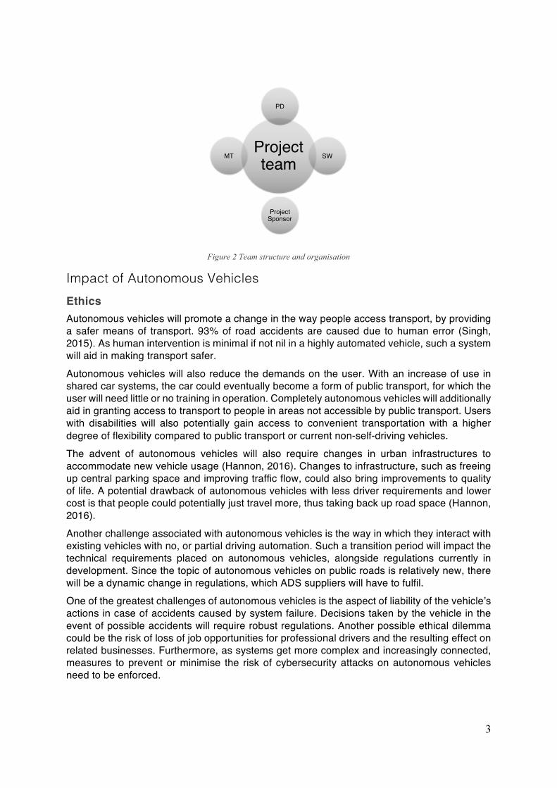
Scope The scope of this project is to develop automated driving technology for Sigma Technology, utilising resources within Sigma and Chalmers. The finished system will be implemented on a 1:10 scaled model of a road-going passenger car and delivered to the company. The original budget for this project was SEK 10,000, funded by Sigma Technology. The timeline of the authors’ work was twenty weeks. The timeline of the thesis work was developed to suit the different team members and their respective availability from other academic commitments during the five-month timeframe. The project members are split into three teams: the authors of this report – the Product Development Team (PD), the Mechatronics Team (MT) and the Software Team (SW). Figure 1 illustrates the work availability of the three teams participating in the project. Figure 2 illustrates the team organisation and structure.
Figure 1 Workload timeline of the three teams part of the project
3
Figure 2 Team structure and organisation
Impact of Autonomous Vehicles Ethics Autonomous vehicles will promote a change in the way people access transport, by providing a safer means of transport. 93% of road accidents are caused due to human error (Singh, 2015). As human intervention is minimal if not nil in a highly automated vehicle, such a system will aid in making transport safer. Autonomous vehicles will also reduce the demands on the user. With an increase of use in shared car systems, the car could eventually become a form of public transport, for which the user will need little or no training in operation. Completely autonomous vehicles will additionally aid in granting access to transport to people in areas not accessible by public transport. Users with disabilities will also potentially gain access to convenient transportation with a higher degree of flexibility compared to public transport or current non-self-driving vehicles. The advent of autonomous vehicles will also require changes in urban infrastructures to accommodate new vehicle usage (Hannon, 2016). Changes to infrastructure, such as freeing up central parking space and improving traffic flow, could also bring improvements to quality of life. A potential drawback of autonomous vehicles with less driver requirements and lower cost is that people could potentially just travel more, thus taking back up road space (Hannon, 2016). Another challenge associated with autonomous vehicles is the way in which they interact with existing vehicles with no, or partial driving automation. Such a transition period will impact the technical requirements placed on autonomous vehicles, alongside regulations currently in development. Since the topic of autonomous vehicles on public roads is relatively new, there will be a dynamic change in regulations, which ADS suppliers will have to fulfil. One of the greatest challenges of autonomous vehicles is the aspect of liability of the vehicle’s actions in case of accidents caused by system failure. Decisions taken by the vehicle in the event of possible accidents will require robust regulations. Another possible ethical dilemma could be the risk of loss of job opportunities for professional drivers and the resulting effect on related businesses. Furthermore, as systems get more complex and increasingly connected, measures to prevent or minimise the risk of cybersecurity attacks on autonomous vehicles need to be enforced.
Projectteam
PD
SW
Project Sponsor
MT
4
Environment Alongside more efficient drivetrain systems for vehicles that come with advancements in technology, autonomous vehicles can provide more efficient use of resources, as the vehicles can be used by multiple users and for multiple purposes. The potential impact these highly automated vehicles will have on transportation of people and goods could be significant.
Economical Considering that purchasing and maintaining a vehicle as a means of transportation is a major expense for many people in the world, autonomous vehicles will help in making individual transport more economical and hassle free. Car ownership could be replaced with a service that will be used on a need basis and can easily reach people in need of transport in different areas, with less requirements on the users. A McKinsey article (Bertoncello & Wee, 2015) points out that autonomous vehicles could free up as much as fifty minutes each day for users, time that could be spent on other activities. A report by Strategy Analytics (2017) estimates that the revenue from services resulting from autonomous vehicles will reach 13.8 trillion SEK by 2050 in Europe.
Research Questions Considering this potential impact on transportation, this thesis report aims to answer the following first research question: RQ1: What are the key technologies to achieve high levels of automated driving? Although Ulrich and Eppinger’s (2012) definition of a development process generally stands true for both physical, as well as software products, new complex products require a strong collaboration and integration between different specialties used to working within different processes and with different working methods. As the product under development is a complex system that is to be developed by a multidisciplinary team, this report aims to answer a second research question which is equally important as the first: RQ2: Can agile methods, more specifically the Scrum framework, be used in multidisciplinary technology development projects?
Outline This report details the development process and technology decisions taken in the development of an ADS. Following this introduction to the thesis report, a second chapter introduces the reader to the current state of ADS by describing some basic technologies used in ADS systems, market trends, a user study to understand what the ADS system means to its potential customers, along with regulations and guidelines on ADS development. The third chapter presents the 1:10 scale vehicle developed in the project, including details on the process of establishing requirements, the hardware and software selection and implementation along with the resulting vehicle. In the fourth chapter the development process along with the Scrum framework are outlined and results on their use are presented. The fifth chapter discusses the authors’ findings and presents future work to be undertaken by the company in the development of the vehicle. The final chapter of this report concludes on the findings with respect to the research questions. The implementation of the technical solutions in this project are not the focus of this thesis, as they are presented in the other three thesis reports resulting from the other team members’ work in the project.
5
2. Automated Driving System 2.1. Technology Overview
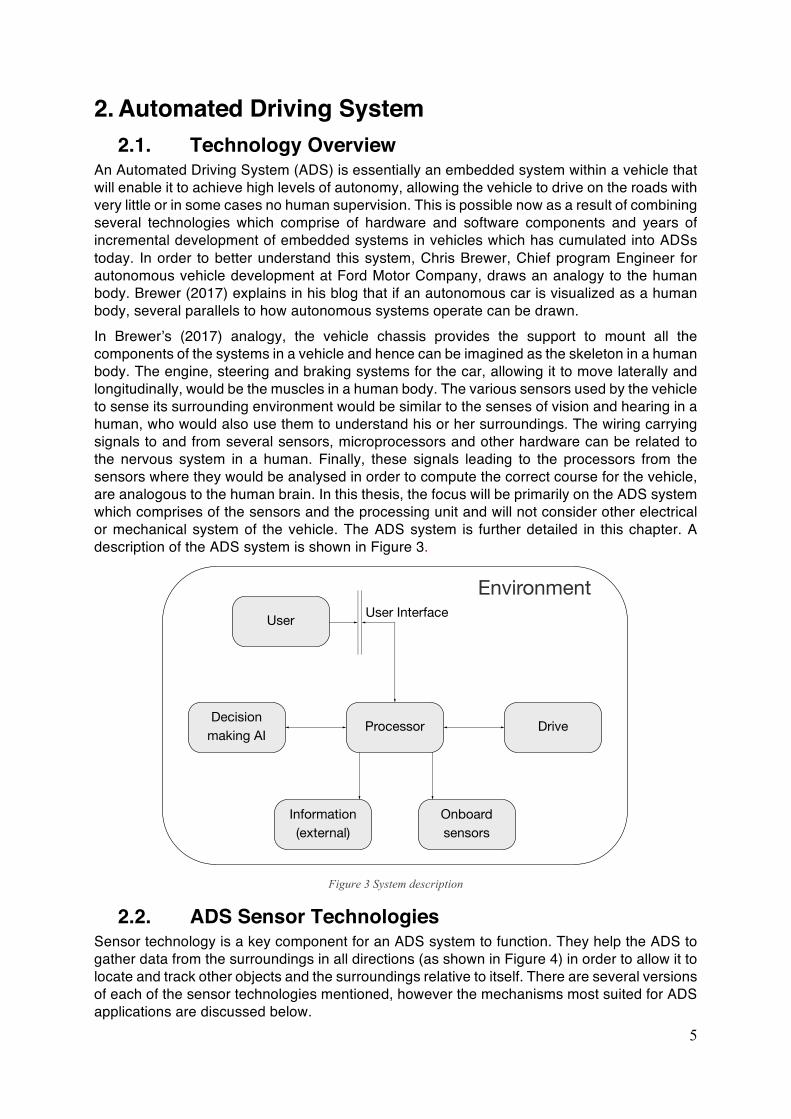
An Automated Driving System (ADS) is essentially an embedded system within a vehicle that will enable it to achieve high levels of autonomy, allowing the vehicle to drive on the roads with very little or in some cases no human supervision. This is possible now as a result of combining several technologies which comprise of hardware and software components and years of incremental development of embedded systems in vehicles which has cumulated into ADSs today. In order to better understand this system, Chris Brewer, Chief program Engineer for autonomous vehicle development at Ford Motor Company, draws an analogy to the human body. Brewer (2017) explains in his blog that if an autonomous car is visualized as a human body, several parallels to how autonomous systems operate can be drawn. In Brewer’s (2017) analogy, the vehicle chassis provides the support to mount all the components of the systems in a vehicle and hence can be imagined as the skeleton in a human body. The engine, steering and braking systems for the car, allowing it to move laterally and longitudinally, would be the muscles in a human body. The various sensors used by the vehicle to sense its surrounding environment would be similar to the senses of vision and hearing in a human, who would also use them to understand his or her surroundings. The wiring carrying signals to and from several sensors, microprocessors and other hardware can be related to the nervous system in a human. Finally, these signals leading to the processors from the sensors where they would be analysed in order to compute the correct course for the vehicle, are analogous to the human brain. In this thesis, the focus will be primarily on the ADS system which comprises of the sensors and the processing unit and will not consider other electrical or mechanical system of the vehicle. The ADS system is further detailed in this chapter. A description of the ADS system is shown in Figure 3.
Figure 3 System description
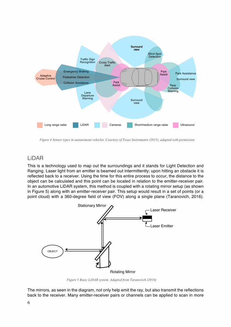
2.2. ADS Sensor Technologies Sensor technology is a key component for an ADS system to function. They help the ADS to gather data from the surroundings in all directions (as shown in Figure 4) in order to allow it to locate and track other objects and the surroundings relative to itself. There are several versions of each of the sensor technologies mentioned, however the mechanisms most suited for ADS applications are discussed below.
6
LiDAR This is a technology used to map out the surroundings and it stands for Light Detection and Ranging. Laser light from an emitter is beamed out intermittently; upon hitting an obstacle it is reflected back to a receiver. Using the time for this entire process to occur, the distance to the object can be calculated and this point can be located in relation to the emitter-receiver pair. In an automotive LiDAR system, this method is coupled with a rotating mirror setup (as shown in Figure 5) along with an emitter-receiver pair. This setup would result in a set of points (or a point cloud) with a 360-degree field of view (FOV) along a single plane (Taranovich, 2016).
The mirrors, as seen in the diagram, not only help emit the ray, but also transmit the reflections back to the receiver. Many emitter-receiver pairs or channels can be applied to scan in more
Figure 4 Sensor types in autonomous vehicles. Courtesy of Texas Instruments (2015), adapted with permission
Figure 5 Basic LiDAR system. Adapted from Taranovich (2016)
7
planes to get higher resolution point cloud, with some commercial automotive LiDAR having up to 64 channels. The rotation rate can be increased to obtain a higher refresh rate, with automotive LiDAR systems being able to provide refresh rates of up to 15Hz. This can be used to gather data about the environment and map out potential obstacles for the ADS to avoid. LiDAR systems can provide great amount of information with lot of data points and high refresh rates even in poor lighting conditions. A drawback is that these systems are currently expensive for mass-market applications. This however is soon changing as companies like Waymo could potentially lower the price of a LiDAR system by 90% (Keith Naughton, 2017).
Radar Radar - which stands for Radio Distance and Ranging - is another technology that is used to detect objects in the vehicle’s environment. It utilizes radio waves (instead of light, as is the case with LiDAR) to detect an object’s range and position relative to the observer. Electromagnetic waves of a particular wavelength are generated from an emitter. The waves, when incident upon a target, bounce back as an echo which is then received by the receiver. The time between transmission and reception gives the distance of the object and the angle of the returned waves which are echoed yields the direction of motion of a moving object in the line of sight. A substantial amount of energy is lost by the echo of the waves hence the received signal needs to be amplified before being analysed. The speed of the moving target can be obtained by analysing the echoed signal. Automotive radar systems are classified based on ranges of operation. Short Range Radar (SRR) operates up to a range of 30m while Medium Range Radar (MRR) operate up to a range of 70m and Long-Range Radar (LRR) operates up to a range of 200m (Issakov, 2010). The main advantage of an automotive radar system is that they can allow for object detection in poor weather conditions such as heavy rain or snow (Underwood, 2015). It allows for multiple object detection and tracking in the same frame of reference. The major disadvantage of a radar is that while it can track objects, their direction and their approximate size, it cannot offer any more detail about the object itself (such as colour) hence making it difficult to identify and classify objects. Radar systems are also not efficient in detecting objects that are not in the line of sight within their FOV. They also need setting up time and resources and some systems need calibration for certain use cases.
Ultrasound Sensors Ultrasonic sensors are very similar to Radar sensors; they are primarily used to detect objects at short distances. An ultrasound transducer, a device that converts sound to electrical signals and vice versa, emits ultrasound waves of frequency between 40 to 60kHz. On encountering an object, the wave bounces back towards the same transducer which converts the reflected sound waves back to electrical signals. The time between the emission and the reception will yield the distance to the object. The effective range of this sensor is between 30cm and 450cm (Nordevall, 2015). Advantages of an ultrasound sensors are their relative simplicity and low cost. They are mainly used for close proximity object detection applications and cannot be used to detect objects at long distances. Since the range calculations depend on the speed of sound in a given medium, the ambient weather and temperature can affect the result from the sensor. Another disadvantage is that ultrasonic sensors do not work well when detecting flat surfaces in certain angles; this is because the original wave can be reflected away from the sender/receiver when incident on a flat surface, hence the receiver might never register a return signal (Yamauchi, 2010).
8
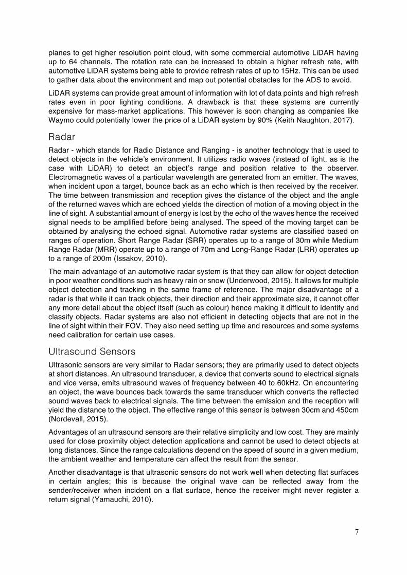
Camera System In essence, a digital camera consists of a sensor that converts incident light into an electrical signal. A digital sensor can be sensitive to different light spectrums, for example, visible light, infrared, ultraviolet etc. A suitable lens needs to be chosen in order to obtain a clear image on the sensor. The lens determines the level of magnification of the image. Lenses may have fixed, or a range of apertures and focal lengths. For automotive use, fixed aperture and focal length lenses are mainly used as seen in existing commercial systems for vehicles. The focal length and the sensor size of the camera defines the FOV of the camera system. For a given sensor size, the wider the FOV, more of the scene can be captured. The narrower the FOV, lesser parts of the scene can be captured but greater magnification is achieved to obtain a more detailed view of the scene. The varying fields of view of a scene obtained from lenses of different focal lengths is shown in Figure 6, with the first image having a FOV of 110deg, with the same scene in the second image being depicted with the FOV of 75 degrees. The images are produced with Nikon’s lens simulator tool (Nikon, 2017).
Figure 6 Scene capture with lens FOVs of 110° (top) and 75° (bottom)
Both narrow and wide-angle camera systems are used to obtain more detail from the environment of the vehicle. The video data gathered from the cameras is analysed and
9
processed further to extract information about objects and obstacles in the vehicle’s path. This is how an ADS can classify objects in 2D and distinguish between various objects in its environment. There are methods to obtain depth information from the camera data as well; this functionality would add more information about the scene. While data from a conventional camera can be used to detect some depth information based on the pixel size the image covers, it cannot accurately assess the exact distances between the objects and in relation to the observer (Dubey, 2016). One example of its limitation would be the inability to distinguish a small person standing nearby as compared to a tall person who is standing far away, both of them will be registered as the same size when it comes to pixel coverage. This is where stereo cameras can be used to obtain exact distances of objects. The algorithm is stable and reliable as it has been used for a long time (Dubey, 2016). Stereo cameras are two cameras that is placed in parallel with a known distance to capture the same scene. Depth information from a scene is obtained from comparing the change in position of various points in the image data captured from the two cameras. This method however, needs high computation power to provide a good compromise of range and accuracy, hence can lead to high cost and complexity. (Dubey, 2016) Generally, camera systems are very reliable and in some cases very economically viable. However, they are adversely affected during night time and bad weather. There are systems that use infrared and other spectrum to deliver the same performance, however they also have limitations during day time, when there is a lot of UV and infrared radiations, hence making the camera systems complex and expensive for all types of scenarios (Yamauchi, 2010).
2.3. Accelerators of ADS Development Artificial Intelligence (AI) in the form of Machine Learning, is one of the key accelerators to develop ADS enabled vehicles. Machine learning is a term given to a process of using algorithms to understand, or ‘train’, based on large variety of data from the different sensors within and external to the vehicle. Based on this ‘training’, the algorithms can make predictions of outcomes when posed with driving situations, thus enabling the vehicle to drive autonomously. This method will allow for quicker turnaround of software functions as it avoids coding individual routine with specific individual instructions for a given function. However, this method needs large amounts of data and computational power, with which these complex algorithms or models can learn or be ‘trained’. Rapid advances in the data storage coupled with wide availability of data about the environment, when communicated to vehicles from different sources (V2X) (Brandl, 2016), aids in making ADSs more robust. One method is by granting the vehicle access to relevant information about infrastructure – road signs, speed limits etc. – which is called vehicle-to-infrastructure (V2I). There is also the possibility of information exchange between vehicles called vehicle-to-vehicle (V2V) which could reduce the dependency of on-board hardware like cameras and LiDARs to detect events and objects in the surroundings hence making the system safer and robust. Recent developments in Simultaneous Localization and Mapping (SLAM) environment mapping technique, can help vehicles get geographic and structural information about the surroundings and link it to maps of the surroundings that can help in making ADS perform well in crowded situations. A Geographic Information System (GIS) (Philippe Bonnifait, 2007) which plots accurate maps of the 3D environment by using existing 3D scans and linking it to various landmarks or features can be used by ADS to navigate complex urban areas. In order to train these vast data models, effective computing power is required and this is where the GPU based computing can be utilized. Rather than using only the Central Processing Unit (CPU) for computing, some companies like Nvidia, a Graphics Processing Unit (GPU)
10
manufacturer, have developed a repackaged version of its parallel computing architecture used in computer graphics solutions to be used in Machine Learning applications. Pioneered in 2007 by Nvidia (2017), GPU accelerated computing is when the CPU is used to carry out the sequential parts of a program, while running some of the compute intensive parts of the program on the GPU. In the case of the ADS development, the ‘training’ for the virtual models and predicting outputs based on the ‘trained’ virtual models, can be carried out on the GPU. The advantages of the parallel computing architecture enable certain compute intensive code to be processed in parallel. An application of GPU accelerated computing for a Machine Learning application for ADS development was used in this project and is discussed further in section Final Software Setup.
2.4. Mergers and Acquisitions in Industry An ADS is a combination of technologies used to make driving safe. It consists of several types of sensors along with several data inputs to obtain information of the surroundings and makes decisions to perform safe manoeuvres on the road. Hence any company interested to develop ADS would need to consider developing and/or acquiring these technologies. A look into the current technology trends shows that there is a great interest in this area. This is clearly indicated by the Gartner hype cycle for 2017 (Gartner, 2017). It indicates that Autonomous Vehicles have continued high expectations for approximately the past 10 years. The projected interest can be supported by big multinationals making large investments in the form of acquisitions in this field. For example Intel purchasing Mobileye, a leader in computer vision, for $15.3 billion (Lunden, 2017). Continuing in the field of computer vision, Sony unveiled the IMX390CQV sensor (Sony, 2017) which is targeted for use in automated driving applications. Other ADS hardware components that are being developed and optimized are LiDAR systems, with Waymo, a dominant technology company, investing resources to reduce LiDAR prices by 90% to make it more affordable for deployment in ADS applications (Keith Naughton, 2017). The interest in this field has also brought in transport service provider Uber to develop ADS systems (Hawkins, 2017). Another transport service provider Lyft has collaborated with Waymo to develop products and services using ADSs (McCormick, 2017). Collaborations between big automotive manufacturers and OEM companies are also observed. Zenuity is one such company which is formed out of a joint venture between Volvo Cars and OEM supplier Autoliv. Referring to the Gartner hype cycle again, another technology that is also in the peak of expectations is AI; this is a complementary technology used in the decision-making aspect of the ADS. Hence, a lot of emphasis on development and acquisitions are observed in this field. One such example is Ford Motor company acquiring an artificial intelligence company Argo AI for $1 billion (Hull, 2017). Hence there is a lot of investment in terms of capital and resources in ADS development from companies operating in several disciplines which indicates a strong future for development in this field.
2.5. Market Trends Autonomous vehicles have the potential to significantly impact transportation, as discussed in the introduction chapter. From an ethical standpoint, the safety benefits of autonomous vehicles are a strong reason to push towards bringing this technology onto public roads. Deloitte’s Global Automotive Consumer Study (2014) finds out that respondents representing generation Y – people born between 1980 and 2000 – have high expectations of new vehicle technology. Some of the findings are listed below, taken from Deloitte’s (2014) study:
• 79% of generation Y respondents expect benefits of new technology in vehicles that aids driving and prevents crashes
• 72% of generation Y responded that they expect benefits from technology which recognises the presence of other vehicles on the road
11
• 59% of generation Y respondents expect benefits from technology that prevents them from engaging in dangerous situations
• 52% of generation Y respondents expect vehicle technology that makes them feel safe and secure
However, in the same survey, only 27% of respondents from generation Y stated that they are willing to pay more than 28,000 SEK for connectivity and safety features. A newer study by Deloitte (2017), integrating learnings from all of their past studies, focuses on consumer opinions on advanced vehicle technology, while also highlighting several trends. The countries in focus are South Korea, India, Germany, Japan, US and China. Some of the interesting findings in Deloitte’s 2017 report are listed below, taken from Deloitte (2017) and adapted:
• since 2014, enthusiasm for fully autonomous vehicles decreased in countries like South Korea and India, increased in China and the US, while in Japan and Germany it has stayed relatively flat
• Between 62% and 81% of consumers are sceptical if fully autonomous vehicles will be safe, depending on the country
• Between 47% and 81% of consumers are more likely to ride in a fully autonomous vehicle if an established track record of such cars being safely used exists
• With the exception of China and South Korea, consumers are generally more inclined to trust the traditional car manufacturers to bring fully autonomous vehicles to market, as opposed to technology companies
• Consumers view safety features as the most useful among advanced vehicle technologies. The top safety features are: object recognition and collision avoidance, informing the driver of dangerous driving situations, blocking the driver from dangerous driving situations, taking steps in medical emergency or accident. “Auto-pilot” modes for both highway and urban driving were interestingly viewed as least useful
• Between 48% and 75% of consumers are not willing to spend more than 4000 SEK on self-driving technologies, a significant decline from the 2014 study
• Consumers expect once premium technology features to become standard, at no extra cost With respect to standard safety technology fitted to vehicles, automotive manufacturers are indeed offering more in recent years. According to a recent overview of the fitment of advanced driver assistance systems presented by Consumer Reports (2017), in Volvo’s own line-up of cars, the 2017 V90 model is fitted with five out of seven such systems, while the previous V70 generation it replaces, in 2016, included just one of the seven as standard, the rest being optional extras (Consumer Reports, 2017). Tesla models X and S come equipped with six of seven systems as standard (Consumer Reports, 2017). Other car manufacturers follow a similar trend, even though safety features are reduced in number. With suppliers claiming to introduce highly automated driving systems on the market starting as early as 2017 for Level 3 systems, and 2018 for Level 4 systems (Shapiro, 2017), there is clearly a valuable market opportunity for developing ADSs. Sigma Technology Development is therefore well positioned to offer its competences in embedded development to companies in and outside of Gothenburg working with ADSs. Companies like Zenuity, Autoliv, and Volvo are all pushing towards a future of automated driving.
12
2.6. Benchmarking In order to understand the state of the art systems being developed or deployed in the market a benchmarking analysis was carried out. Every major automobile manufacturer is developing their own version of an ADS either in house or in collaboration with a technology company. Apart from companies in the automotive industry, some technology and transport companies such as Google, Uber and Lyft are also involved in development of technology in this area. All the above autonomous systems are in varying levels of development, with each firm making rapid progress towards increasing levels of autonomy. The progress in these projects are publicized and documented more often by some companies, than others. In order to understand the cutting edge in the limited time available, the benchmarking process is limited to companies that were leading development activities, with some fielding products for sale with an ADS system close to Level 4. Along with the level of autonomy, the benchmarking process (Appendix B) also focused on the hardware used by each manufacturer. This revealed that apart from a similar array of cameras, radar and ultrasound sensors, the use of LiDAR was a differentiating factor between firms, with BMW, Google and Volvo using LiDAR based systems. For example, Google (Krafcik, 2016) use LiDAR along with cameras and ultrasound sensors. However, Tesla is the only company that uses only a combination of cameras and radar to achieve high levels of autonomy in its products (Tesla, 2017). As mentioned in the previous chapter, there is a lot of activity in this field of technology with many big firms such as Intel, Bosch and many relevant OEM companies that are joining together to develop solutions in this area.
2.7. Effect of ADS on Economy Vehicles equipped with ADS can revolutionize the way people access transport which can have a large economic impact on the automotive industry; these effects are detailed in a report by (Lewis M. Clements, 2017) . Summarizing relevant parts of the report, autonomous vehicles will dominate the automotive industry due to the ‘on-demand’ availability of transport, the private ownership of cars will decrease. Car rental services like Uber, Lyft etc. will increase their presence using Autonomous Vehicles. If car sharing services become popular then Forbes Magazine estimates that cost of transportation per mile could drop five to ten-fold, though these estimates might not be accurate because it is dependent on people’s rate of adoption to this mode of travel and because of some vehicles that might be traveling unoccupied (Diamandis, 2014). Currently software constitutes approximately 10% of vehicle value, as the focus shifts from hardware of the car (body, powertrain, interior, lighting, and other basic components) to software, it can be argued that the hardware can become commoditized and this can potentially lead to a drop in the value of the hardware to 40% (Jonas, Byrd, Shanker, & Ono, 2014). It can be observed that software companies like Google, Apple and Microsoft may use the vehicle hardware as a platform to deliver software, analogous to the smartphone industry. Currently, the way that the vehicles have been insured is also an area that would see changes as autonomous vehicles become popular. Even with low levels of automation in current day vehicles for example systems with just front crash prevention technology, insurance claims have decreased by 7-15% (Albright, Bell, Schneider, & Nyce, 2015). When considering higher levels of autonomy, the insurance companies would have to change their business models and the type of insurance packages they offer. Therefore, cars which can drive more efficiently, by being able to utilize techniques such as platooning and having access to data from the environment could decrease congestion and save fuel. Reduction in congestion can reduce some of the $101 billion fuel costs currently experienced by the America market (Silberg & Wallace, 2012). It is clear that that ADSs will impact several areas financially and in most cases warranting a radical restructuring of business models.
13
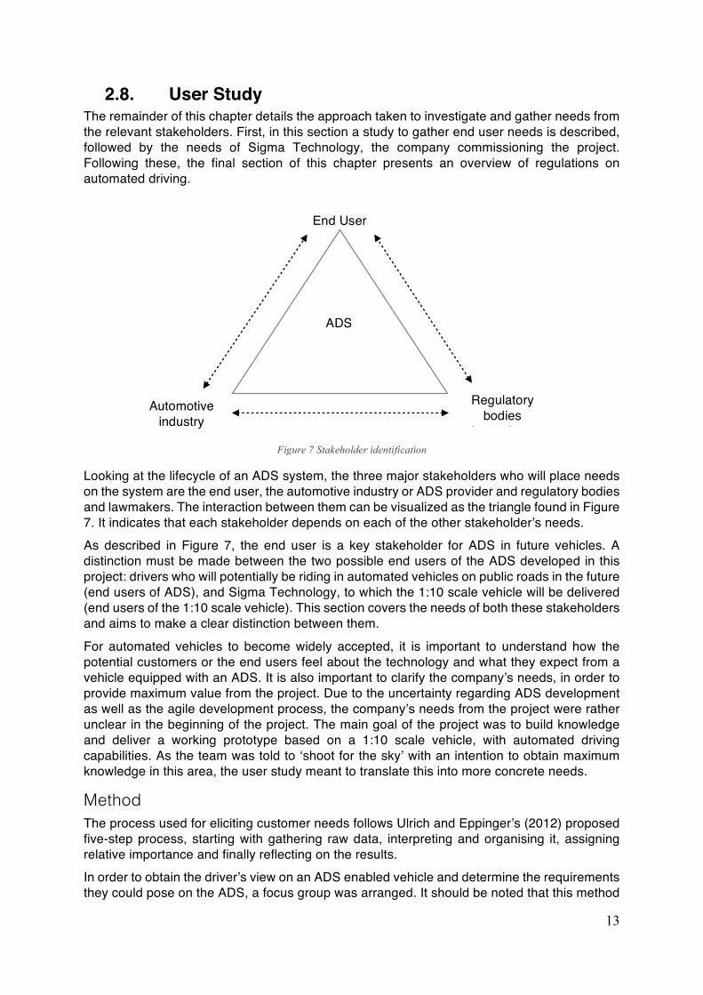
2.8. User Study The remainder of this chapter details the approach taken to investigate and gather needs from the relevant stakeholders. First, in this section a study to gather end user needs is described, followed by the needs of Sigma Technology, the company commissioning the project. Following these, the final section of this chapter presents an overview of regulations on automated driving.
Looking at the lifecycle of an ADS system, the three major stakeholders who will place needs on the system are the end user, the automotive industry or ADS provider and regulatory bodies and lawmakers. The interaction between them can be visualized as the triangle found in Figure 7. It indicates that each stakeholder depends on each of the other stakeholder’s needs. As described in Figure 7, the end user is a key stakeholder for ADS in future vehicles. A distinction must be made between the two possible end users of the ADS developed in this project: drivers who will potentially be riding in automated vehicles on public roads in the future (end users of ADS), and Sigma Technology, to which the 1:10 scale vehicle will be delivered (end users of the 1:10 scale vehicle). This section covers the needs of both these stakeholders and aims to make a clear distinction between them. For automated vehicles to become widely accepted, it is important to understand how the potential customers or the end users feel about the technology and what they expect from a vehicle equipped with an ADS. It is also important to clarify the company’s needs, in order to provide maximum value from the project. Due to the uncertainty regarding ADS development as well as the agile development process, the company’s needs from the project were rather unclear in the beginning of the project. The main goal of the project was to build knowledge and deliver a working prototype based on a 1:10 scale vehicle, with automated driving capabilities. As the team was told to ‘shoot for the sky’ with an intention to obtain maximum knowledge in this area, the user study meant to translate this into more concrete needs.
Method The process used for eliciting customer needs follows Ulrich and Eppinger’s (2012) proposed five-step process, starting with gathering raw data, interpreting and organising it, assigning relative importance and finally reflecting on the results. In order to obtain the driver’s view on an ADS enabled vehicle and determine the requirements they could pose on the ADS, a focus group was arranged. It should be noted that this method
Regulatory bodies
lawmakers
ADS
End User
Automotive industry
Figure 7 Stakeholder identification
14
was chosen due to time constraint and the method’s ability to reach a group of people to understand the user’s impression of the technology. Focus groups are usually used to obtain an understanding of the users of the product (Joy Frechtling, 1997). This method is used in this thesis as an exploratory method to obtain information effectively in a relatively short amount of time. The participants for this study included people between the ages of 24 and 35 years; this age group being referred to as generation Y. This set of users are most inclined to accepting high levels of automation in a vehicle. According to a study conducted by MIT Agelabs (Hillary Abraham, 2016), 61% of the people of generation Y in the study were comfortable with vehicles being completely autonomous. Deloitte’s Global Automotive Consumer Study (2014) furthermore found that generation Y customers expect various safety benefits from future vehicles, as discussed in the Market Trends section. Apart from that, it was also easy to get participation from this age group as they are young professionals or students who can spare time. Once the generation Y participants were identified, some questions about how the ADS would affect the driver were brainstormed between the thesis authors. It was observed that most of the points for discussion were leading to how the users would interact with the machine, the human machine interface aspect of the product which was not within the scope of the thesis. Hence it was important to ensure that topics to be discussed were linked to needs related to the embedded ADS. The topics selected were trust with respect to ADS, transparency with respect to the functioning of the ADS and finally the method preferred to consume the service. These topics were framed into seven questions. The focus group consisted of seven participants – a mix of students and professionals. They were offered coffee and some snacks as suggested by Joy Frechtling (1997) before the commencement of discussion to enable them to relax and contribute to the discussion. The focus group was carried out in a well-lit conference room with an oval conference table surrounded by chairs, such that the participants could face each other. There was a small presentation to introduce the participants to the context of discussion and the basic functioning of the ADS system; this would act as the mediating material for the discussion to grow. Following the introduction, the set of seven questions were presented one at a time to the group. The focus group was conducted by the thesis authors, where one author moderated the focus group, while the other recorded and monitored the progress of the discussion. Audio of the discussion was recorded with permission and some key points were noted. The recording was transcribed and the notes from the focus group were collected. The quotes that were most suited towards the scope were chosen. A data reduction process (Joy Frechtling, 1997) was carried out with the aim to obtain data which emphasizes relevant areas to the project. The quotes were then grouped into different categories such as trust, transparency, willingness and miscellaneous issues. On the other hand, the company’s needs were elicited during several interactions with key internal stakeholders during the course of the project. Besides regular meetings, two dedicated semi-structured interviews were held with the project sponsor. Additionally, an investigation into the possible use cases of the prototype 1:10 scale vehicle was also conducted with managers within the company as well as the person in charge of public relations. Interview guides were created following discussions between the thesis authors. The three data collection tools for the company’s needs are summarised below:
• Semi-structured group interviews and discussions with the project sponsor • Mid-term presentation discussion with management
• Semi-structured interview with public relations responsible
15
Results Out of the shortlisted quotes resulting from the focus group (Appendix C), one in particular warranted reflection. This was an observation a participant made relating to the prediction of human behaviour. This need was converted to a user need and was added to the requirements list for a road-going highly automated vehicle.
“The other thing would be, how would the car anticipate human behaviour?”
Another interesting quote that warranted reflection was:
“the car would adapt to my desire and stay there [in the lane] or [know that] I am in a rush today and please take the fastest lane as that’s where the cars are going fast”
The participant would like to have the freedom of directing the vehicle based on their observation of road/traffic conditions, while the system is still engaged and performing the driving task. SAE’s J3016 document does not specifically mention this for an ADS (levels three to 5). According to SAE, while the ADS is engaged, it will immediately disengage in a level 3 system, it may delay hand-over to user in level 4 until appropriate, or must delay hand-over at full driving automation. Assuming the vehicle is well designed, tested and validated, the decisions it takes in driving are based on data and road conditions. The particular case of a user request to direct the system while engaged is not currently prescribed or exemplified by SAE. This raises multiple questions on how the users envision automated driving at these early stages, as well as how regulatory bodies will cover the topic. However, this highlights one of the challenges that needs to be overcome to enable acceptance of ADS, enabling vehicles to gain trust within people in order for them accept this new technology. It should also be noted that the single focus group is not sufficient to fully understand what the customer demographic for a product thinks and perceives. The conducted focus group does however provide a glimpse into what potential customers feel about ADS functionality in a vehicle. As mentioned previously, the company’s needs from the project evolved during the course of the project. The following two statements represent the fundamental needs that were elicited:
• The vehicle needs to be able to stay within lanes • The vehicle needs to be able to detect obstacles and perform an emergency stop. A
desire would be to have the vehicle manoeuvre around the obstacle and continue its journey
A possible third, more vague need, was expressed for the first time during the discussion following the mid-term presentation for company management: having the 1:10 scale vehicle as a showcase prototype at fairs and company events. Upon further investigation into this, a late semi-structured interview added some more details on the environment the prototype vehicle could potentially be exhibited in:
• There are six to seven fairs of varying sizes the company regularly attends every year, in addition to events held at the company headquarters
• Equipment usually brought to fairs includes one or two small tables, a booth, as well as a TV screen. Fair stands allotted to exhibitors are usually six square meters in footprint
• Access to plug-points is readily available at fairs
• Fairs last from 09:00 to 16:00 usually. Demos could potentially be held during high traffic periods, such as lunchtime or between 13:00 to 14:30
• Fair layout can vary from corner booth to open space, therefore vehicle positioning at the stand can be hard to foresee
16
• Possibility of having a video demo of the vehicle, along with photographs
• Vehicle demoes should be kept short, as the main purpose is to get to know the event attendants
• The vehicle will be transported by car to the event, so vehicle weight and accessories are not an issue
Due to these needs being expressed late in the project, potential knowledge gaps are also highlighted. There is clearly an opportunity to further investigate how the vehicle can best be used as a showcase at exhibitions and fairs. These stated company needs are prioritised to ensure development resources are allocated appropriately. In the order of importance, the interpreted company needs are presented in the following list:
1. The vehicle performs lane-keeping 2. The vehicle has obstacle detection and collision avoidance capability 3. The vehicle is packaged such that it allows for use at exhibitions
Prioritisation was done in order to ensure that the vehicle functionality would reach the company’s expectations for the product. Due to the uncertainty involved in using deep learning to train the vehicle, this was essential to provide a quick overview of the most important vehicle features. These needs from the potential end users and from Sigma Technology were used as a basis for developing product requirements, a process which is described in the Requirements section.
2.9. Regulations on ADS The search for legislation on ADS was initiated early on in the project. A document by Volvo (Eugensson, 2016) was helpful in pinpointing current legislation taken into consideration when developing Volvo’s own autonomous vehicles. As one of the deliverables to Sigma Technology Development was a requirements document on ADS development, a study of available legislation was undertaken. A further goal of this study was to ensure learnings from the project were scalable and industry relevant. This section will highlight the most important legislative requirements, along with a discussion on the challenges posed by conflicting requirements and policies within the different markets and their implication for ADS developers.
Table 1 Regulation documents studied and presented
Document Type SAE J3016 Taxonomy - recommended practice Federal Automated Vehicles Policy Policy UNECE
Vienna Convention on Road Traffic of 1968, amended
Working Party on Road Traffic Safety (WP.1)
World Forum for Harmonisation of Vehicle Regulations (WP.29)
Regulations
There are many sources for regulatory documentation available and this area would require a considerable amount of time to fully explore. Therefore, the focus of this study is on regulations in Europe and the United States, as these are readily available, transparent and they represent major markets for ADS development. The documents that make up this study are specified in Table 1. The list is made up of both regulations and guidelines. This section will highlight
17
important legal factors to consider from each of these documents. For ease of reading, they are detailed one by one. It must be mentioned that the ISO 26262 standard (covering road vehicles functional safety) was not considered for this project, due to it applying to safety related systems installed in series production cars. Considering the prototype developed in this project was meant as a technology development exercise, the requirements from the standard were considered to be not within the scope. However, the standard gives out requirements for validation, which might prove useful for this project. Due to the time constraints, there were no resources left to focus on this aspect, but it is strongly recommended that an investigation into this standard is made if further development is to be made on the ADS.
SAE J3016 This document “provides a taxonomy describing the full range of levels of driving automation in on-road motor vehicles and includes functional definitions for advanced levels of driving automation and related terms and definitions” (SAE, 2016). Alongside these, the different functions are described with practical examples according to the different levels. This document has proved useful in bringing clarity in the development process during this project; other regulatory documents (such as NHTSA’s) have adopted the definition of the levels of driving automation from this SAE document. However, this document does not include active safety systems that are not engaged on a sustained basis and rather just provide momentary intervention. As such, the focus is only on systems which automate (transfer from the human to computer control) part or all of the dynamic driving task (SAE, 2016). The different levels of driving automation outlined by SAE are specified in relation to four criteria: sustained vehicle motion control, object and event detection and response (OEDR), dynamic driving task fallback, and operational design domain. Below, a brief explanation of these terms is given, to aid the reader in later parts of this report. The terms are either taken directly, or adapted from SAE’s J3016 standard. The lateral and longitudinal vehicle motion control effectively correspond to vehicle steering, and acceleration and deceleration control, respectively. Object and Event Detection and Response (OEDR) is the essential element of an ADS system which refers to monitoring the driving environment by performing object and event detection, recognition, classification, as well as response execution to these (SAE, 2016). The dynamic driving task (DDT) is a term which encapsulates both vehicle motion control and OEDR, as well as manoeuvre planning and other auxiliary tasks, such as lighting, signalling, etc. (SAE, 2016). DDT fallback refers to the response of either human driver or ADS, to “perform the DDT or achieve a minimal risk condition”, in case the vehicle experiences DDT system failure or is approaching the exit of its intended driving domain (SAE, 2016). The conditions in which the driving automation system is designed to function in is termed Operational Design Domain (ODD) (SAE, 2016). A minimal risk condition refers to the human driver or ADS performing DDT fallback and bringing the vehicle in a condition that reduces the risk of a crash “when a given trip cannot or should not be completed” (SAE, 2016). SAE (2016) distinguishes between six levels of driving automation, from level 0 corresponding to no automation, to level 5 corresponding to full automation. Levels 0-2 describe systems that still rely on the human driver to perform part or all of the dynamic driving task. These systems fall into the safety and driver assistance systems category. Levels 3-5 describe systems which
18
do not need human intervention while the ADS is engaged, thus performing the entire dynamic driving task. These levels correspond to a Highly Automated Vehicle (SAE, 2016).
Federal Automated Vehicles Policy As part of the US Department of Transport, the NHTSA is a federal agency which regulates the safety of motor vehicles (NHTSA, 2017). NHTSA’s document, Federal Automated Vehicles Policy, has been released in September 2016 and contains useful guidance to manufacturers and other entities in development, testing and deployment of Highly Automated Vehicles (NHTSA, 2016). As a short-term guidance, the document serves as a first step towards a regulatory framework and best practices for ADS developers. The document is made up of four parts, which are briefly described in Table 2 (NHTSA, 2016). Only the first part of this document was studied and is briefly presented in this section. The other sections however are a must-read for any entity interested in developing and deploying a Highly Automated Vehicle or ADS on public roads in the US.
Table 2 Overview of NHTSA Federal Automated Vehicles Policy
Content of NHTSA document 1 Vehicle Performance Guidance for Automated Vehicles
“Best practices for the safe pre-deployment design, development and testing of HAVs [Highly Automated Vehicles] prior to commercial sale or operation on public roads.”
2 Model State Policy “Objective is to ensure the establishment of a consistent national framework rather than a patchwork of incompatible laws.”
3 NHTSA’s current regulatory tools “Provides instructions, practical guidance, and assistance to entities seeking to employ” existing regulatory tools
4 New Tools and Authorities Identifies potential new tools, authorities and regulatory structures that could aid the safe and appropriately expeditious deployment of new technologies by enabling the Agency to be more nimble and flexible
The Vehicle Performance Guidance for Automated Vehicles released by NHTSA although effective, is not mandatory at time of writing this report. However, it provides good overall guidelines for the design, testing and deployment of ADSs and could, in the future with further revisions, be imposed as regulation. The outlined framework applies to both test and production vehicles and its basic prerequisite is adherence to the US Federal Motor Vehicle Safety Standards (FMVSS). The topics relevant to this project are covered in part one of the guide:
• Software and Hardware updates
• System safety
• Human Machine Interface
• Validation Methods
• Operational Design Domain, Object and Event Detection and Response, Fall back and Minimal Risk Condition
• Guidance for Lower Levels of Automated Vehicle Systems
The majority of the requirements presented in the Requirements section have been taken from this guidance document. As this report cannot cover all requirements and due to the iterative nature of this framework’s development, any party interested in ADS development in the US would benefit from a comprehensive study of this document and future updates of it.
19
UNECE In the European Union, regulations regarding automated driving are agreed at United Nations level. The Inland Transport Committee of the United Nations Economic Commission for Europe (UNECE) has over 50 international agreements and conventions in place, “providing an […] legal framework and the technical regulations for the development of international road […] and vehicle construction” (Pillath, 2016). Two permanent subsidiary bodies, the Working Party on Road Traffic Safety (WP.1) and the World Forum for Harmonisation of Vehicle Regulations (WP.29) are relevant to automated driving. The Vienna Convention on Road Traffic of 1968 is an international treaty signed by 73 countries, including all EU member states with the exception of the UK and Spain (Pillath, 2016). This convention was previously a big hindrance towards the introduction of automated vehicles, but with recent amendments enforced March 23rd 2016 (UNECE, 2016) “automated driving technologies transferring driving tasks to the vehicle will be explicitly allowed in traffic, provided that these technologies are in conformity with the United Nations vehicle regulations or can be overridden or switched off by the driver.” The regulations however still state the need for a driver. Swedish regulations to be enforced from 1st July 2017 will make it easier to test automated vehicle testing on public roads (Regeringskansliet, 2017). UN Regulation 79 regarding steering equipment states: “An automatically commanded steering function is allowed only up to 10 km/h (e.g. parking manoeuvres). Above 10 km/h, only the 'corrective steering function' is allowed and no level of steering automation is compatible with the current requirements of UN-Regulation 79. “An amendment would be necessary as a prerequisite to automated driving functions” (Pillath, 2016). UNECE also provides regulations on cybersecurity and data privacy, as well as liability issues. The requirements presented in documents from UNECE are more thorough and specific as compared to any other document studied on the topic of automated drive regulations.
20
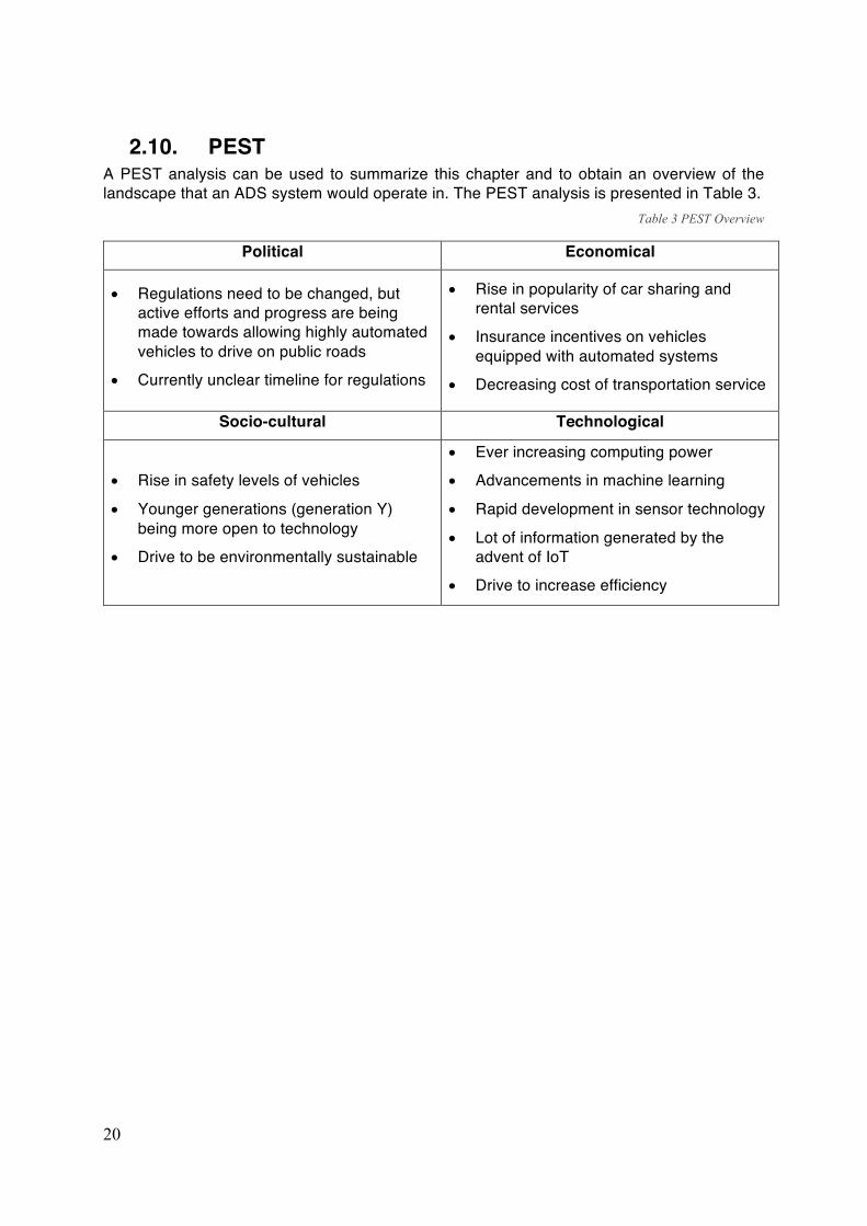
2.10. PEST A PEST analysis can be used to summarize this chapter and to obtain an overview of the landscape that an ADS system would operate in. The PEST analysis is presented in Table 3.
Table 3 PEST Overview
Political Economical
• Regulations need to be changed, but active efforts and progress are being made towards allowing highly automated vehicles to drive on public roads
• Currently unclear timeline for regulations
• Rise in popularity of car sharing and rental services
• Insurance incentives on vehicles equipped with automated systems
• Decreasing cost of transportation service
Socio-cultural Technological
• Rise in safety levels of vehicles
• Younger generations (generation Y) being more open to technology
• Drive to be environmentally sustainable
• Ever increasing computing power • Advancements in machine learning
• Rapid development in sensor technology
• Lot of information generated by the advent of IoT
• Drive to increase efficiency
21
3. The Prototype This chapter details the final vehicle developed in the project, which is based on a 1:10 remote control (RC) vehicle. The section covers customer needs identification for a commercial system and how it was scaled down and converted to requirements for the 1:10 car. It also includes hardware architecture definition, hardware platform, sensor selection, software implementation and results regarding the final functionality of the ADS.
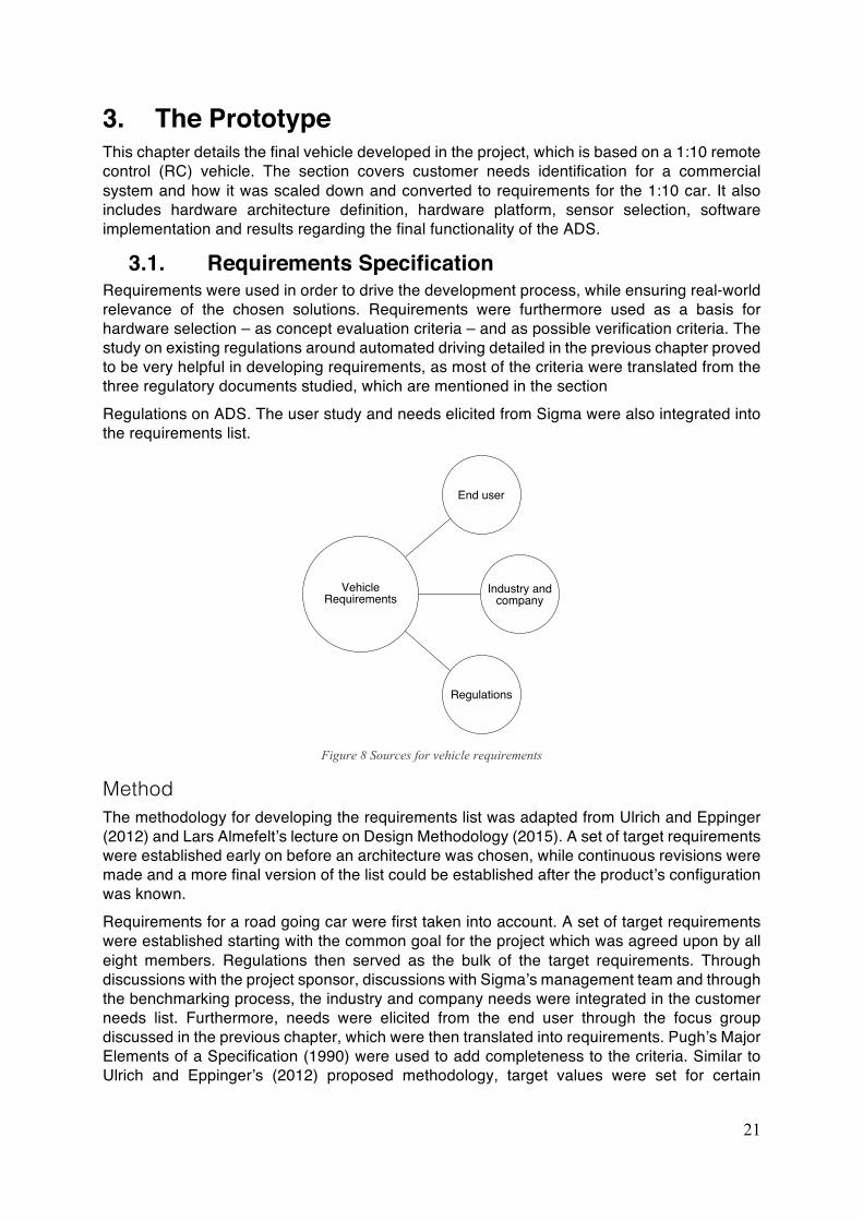
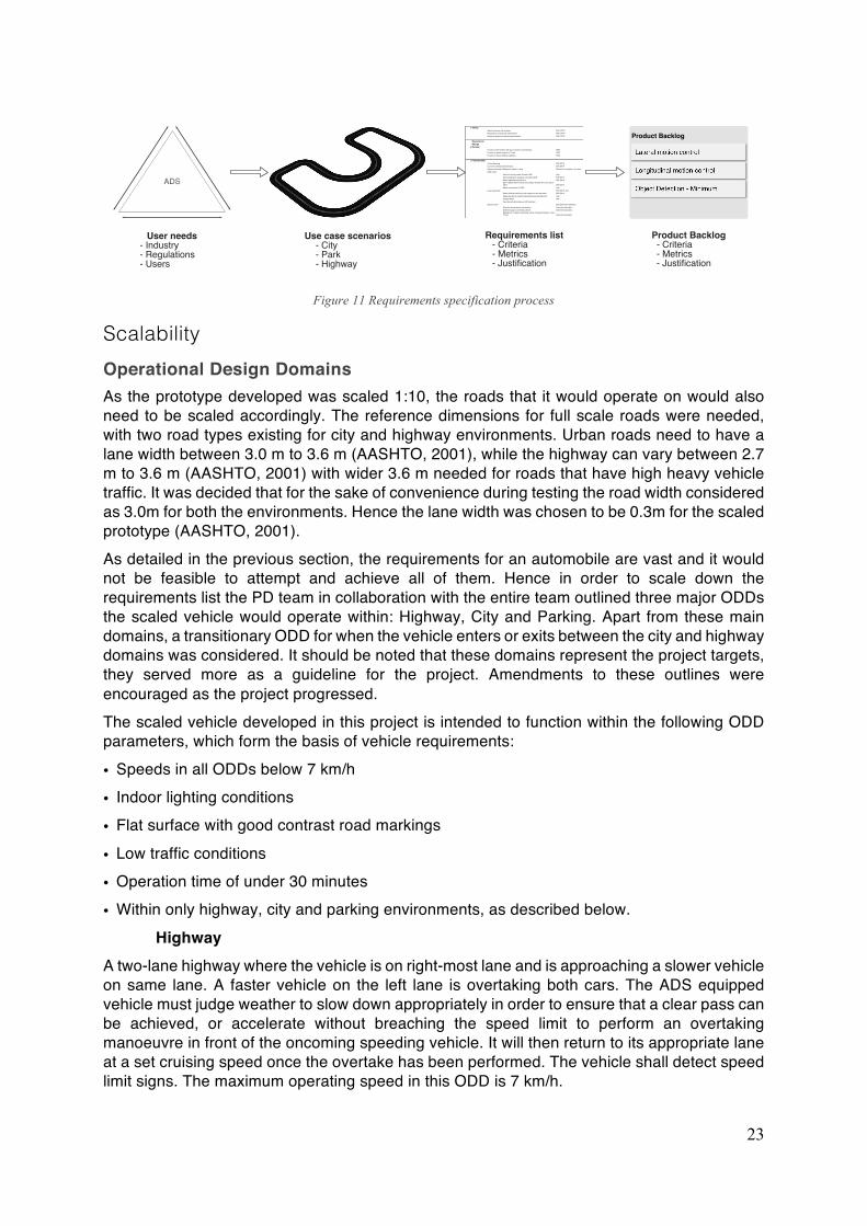
3.1. Requirements Specification Requirements were used in order to drive the development process, while ensuring real-world relevance of the chosen solutions. Requirements were furthermore used as a basis for hardware selection – as concept evaluation criteria – and as possible verification criteria. The study on existing regulations around automated driving detailed in the previous chapter proved to be very helpful in developing requirements, as most of the criteria were translated from the three regulatory documents studied, which are mentioned in the section Regulations on ADS. The user study and needs elicited from Sigma were also integrated into the requirements list.
Figure 8 Sources for vehicle requirements
Method The methodology for developing the requirements list was adapted from Ulrich and Eppinger (2012) and Lars Almefelt’s lecture on Design Methodology (2015). A set of target requirements were established early on before an architecture was chosen, while continuous revisions were made and a more final version of the list could be established after the product’s configuration was known. Requirements for a road going car were first taken into account. A set of target requirements were established starting with the common goal for the project which was agreed upon by all eight members. Regulations then served as the bulk of the target requirements. Through discussions with the project sponsor, discussions with Sigma’s management team and through the benchmarking process, the industry and company needs were integrated in the customer needs list. Furthermore, needs were elicited from the end user through the focus group discussed in the previous chapter, which were then translated into requirements. Pugh’s Major Elements of a Specification (1990) were used to add completeness to the criteria. Similar to Ulrich and Eppinger’s (2012) proposed methodology, target values were set for certain
22
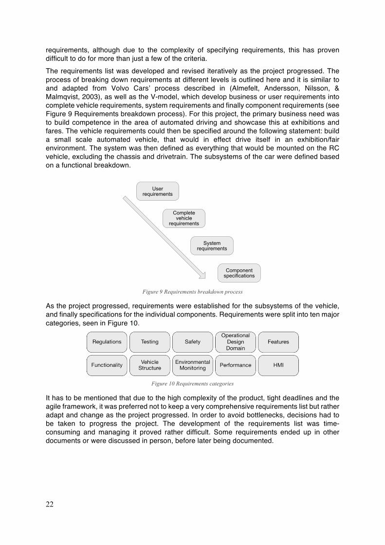
requirements, although due to the complexity of specifying requirements, this has proven difficult to do for more than just a few of the criteria. The requirements list was developed and revised iteratively as the project progressed. The process of breaking down requirements at different levels is outlined here and it is similar to and adapted from Volvo Cars’ process described in (Almefelt, Andersson, Nilsson, & Malmqvist, 2003), as well as the V-model, which develop business or user requirements into complete vehicle requirements, system requirements and finally component requirements (see Figure 9 Requirements breakdown process). For this project, the primary business need was to build competence in the area of automated driving and showcase this at exhibitions and fares. The vehicle requirements could then be specified around the following statement: build a small scale automated vehicle, that would in effect drive itself in an exhibition/fair environment. The system was then defined as everything that would be mounted on the RC vehicle, excluding the chassis and drivetrain. The subsystems of the car were defined based on a functional breakdown.
As the project progressed, requirements were established for the subsystems of the vehicle, and finally specifications for the individual components. Requirements were split into ten major categories, seen in Figure 10.
Figure 10 Requirements categories
It has to be mentioned that due to the high complexity of the product, tight deadlines and the agile framework, it was preferred not to keep a very comprehensive requirements list but rather adapt and change as the project progressed. In order to avoid bottlenecks, decisions had to be taken to progress the project. The development of the requirements list was time-consuming and managing it proved rather difficult. Some requirements ended up in other documents or were discussed in person, before later being documented.
Figure 9 Requirements breakdown process
23
Figure 11 Requirements specification process
Scalability Operational Design Domains As the prototype developed was scaled 1:10, the roads that it would operate on would also need to be scaled accordingly. The reference dimensions for full scale roads were needed, with two road types existing for city and highway environments. Urban roads need to have a lane width between 3.0 m to 3.6 m (AASHTO, 2001), while the highway can vary between 2.7 m to 3.6 m (AASHTO, 2001) with wider 3.6 m needed for roads that have high heavy vehicle traffic. It was decided that for the sake of convenience during testing the road width considered as 3.0m for both the environments. Hence the lane width was chosen to be 0.3m for the scaled prototype (AASHTO, 2001). As detailed in the previous section, the requirements for an automobile are vast and it would not be feasible to attempt and achieve all of them. Hence in order to scale down the requirements list the PD team in collaboration with the entire team outlined three major ODDs the scaled vehicle would operate within: Highway, City and Parking. Apart from these main domains, a transitionary ODD for when the vehicle enters or exits between the city and highway domains was considered. It should be noted that these domains represent the project targets, they served more as a guideline for the project. Amendments to these outlines were encouraged as the project progressed. The scaled vehicle developed in this project is intended to function within the following ODD parameters, which form the basis of vehicle requirements:
• Speeds in all ODDs below 7 km/h
• Indoor lighting conditions
• Flat surface with good contrast road markings
• Low traffic conditions
• Operation time of under 30 minutes
• Within only highway, city and parking environments, as described below. Highway
A two-lane highway where the vehicle is on right-most lane and is approaching a slower vehicle on same lane. A faster vehicle on the left lane is overtaking both cars. The ADS equipped vehicle must judge weather to slow down appropriately in order to ensure that a clear pass can be achieved, or accelerate without breaching the speed limit to perform an overtaking manoeuvre in front of the oncoming speeding vehicle. It will then return to its appropriate lane at a set cruising speed once the overtake has been performed. The vehicle shall detect speed limit signs. The maximum operating speed in this ODD is 7 km/h.
24
Highway to City Transition This is an ODD which is a transitional case where a two-lane highway road would merge into a single city lane. This would need the car to detect this merger and choose the appropriate lane to continue city driving. The vehicle should adjust to city speed limit. Hence the vehicle would need to detect merge signs as well as speed limit signs to adjust speed accordingly. It should be noted that this case can also be reversed for when the vehicle needs to merge back into the highway.
City One four-way crossing (‘+’) will be used for city scenario. One corner can be a traffic light, while the other corner can be a stop/yield sign, with a pedestrian crossing as well. The vehicle must take appropriate actions to navigate the intersection. It should pass through one corner first, move onto another segment and then return to the intersection from a different corner. The vehicle in this scenario should consider the stop/yield sign, recognise traffic signs and a pedestrian crossing, and suitably react to them. The maximum speed in this ODD is 5 km/h.
Parking When the driver engages the parking function, the vehicle scans and detects an empty parking spot by the side of the road and it performs a parallel parking manoeuvre. Then when the vehicle has to start the journey from its parked state, it does so safely after checking for encroaching traffic before merging onto the city road. The vehicle needs to recognise parking signs, while also signalling to other road users of its intended manoeuvres. The speed of the vehicle in this ODD is slower than 1 km/h.
Requirements for Scaled Vehicle As the process of translating regulations into requirements for road-going vehicles proved to be too time-consuming at increasingly finer levels of detail (eg. object classification into pedestrian, police officer, police officer directing traffic, emergency workers etc.), the focus shifted towards the 1:10 scaled vehicle and a new list was established for the three ODDs. Once the hardware architecture was defined, irrelevant requirements were removed. After screening the list against the three predefined ODDs, relevant metrics were scaled down to 1:10 and each of the resulting requirements was assigned to a particular team in the project. This list was then used to develop the backlog to drive the agile development process. Details on how this list is used in the agile process is further discussed in the Implementation of Scrum section of Chapter 4. A full list of requirements for the 1:10 scale vehicle is presented in Appendix A – Requirements List. To ensure the various project needs were balanced, three value drivers were always considered while developing requirements for the scaled car. Value Driven Design methodology was considered, as proposed by (Isaksson et al., 2013). Starting with the most important ones, the three value drivers were: learnings, real-world relevancy, and usability in the exhibition environment. To narrow down development focus, two requirements were found to be crucial to the 1:10 scale vehicle. These two critical requirements were the basis for all decisions taken during development:
• The vehicle achieves minimal risk condition in emergency situations
• The vehicle performs object and event detection:
• The vehicle localises objects in the environment
• The vehicle recognises detail information about the objects
25
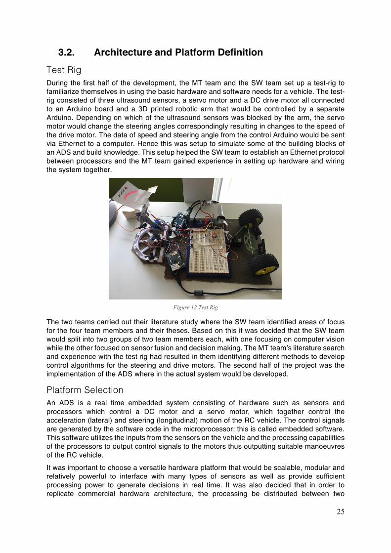
3.2. Architecture and Platform Definition Test Rig During the first half of the development, the MT team and the SW team set up a test-rig to familiarize themselves in using the basic hardware and software needs for a vehicle. The test-rig consisted of three ultrasound sensors, a servo motor and a DC drive motor all connected to an Arduino board and a 3D printed robotic arm that would be controlled by a separate Arduino. Depending on which of the ultrasound sensors was blocked by the arm, the servo motor would change the steering angles correspondingly resulting in changes to the speed of the drive motor. The data of speed and steering angle from the control Arduino would be sent via Ethernet to a computer. Hence this was setup to simulate some of the building blocks of an ADS and build knowledge. This setup helped the SW team to establish an Ethernet protocol between processors and the MT team gained experience in setting up hardware and wiring the system together.
Figure 12 Test Rig
The two teams carried out their literature study where the SW team identified areas of focus for the four team members and their theses. Based on this it was decided that the SW team would split into two groups of two team members each, with one focusing on computer vision while the other focused on sensor fusion and decision making. The MT team’s literature search and experience with the test rig had resulted in them identifying different methods to develop control algorithms for the steering and drive motors. The second half of the project was the implementation of the ADS where in the actual system would be developed.
Platform Selection An ADS is a real time embedded system consisting of hardware such as sensors and processors which control a DC motor and a servo motor, which together control the acceleration (lateral) and steering (longitudinal) motion of the RC vehicle. The control signals are generated by the software code in the microprocessor; this is called embedded software. This software utilizes the inputs from the sensors on the vehicle and the processing capabilities of the processors to output control signals to the motors thus outputting suitable manoeuvres of the RC vehicle. It was important to choose a versatile hardware platform that would be scalable, modular and relatively powerful to interface with many types of sensors as well as provide sufficient processing power to generate decisions in real time. It was also decided that in order to replicate commercial hardware architecture, the processing be distributed between two
26
processors. The first processor (control processor) would control the motors and the second processor (decision processor) would process the data from the sensors and generate decisions that would be communicated to the control processor. Based on the aforementioned setup, components for both the control and the decision processors needed to be chosen. During the initial stages of the project, an Arduino Uno was used by the MT to begin development. As the project progressed and with increased familiarity, it was decided that the Arduino Uno would continue to be the control processor and was used to control the motors for steering and acceleration. This was decided mainly because of the convenience and the familiarity with both the MT and ST team to use this component. Choosing a suitable component to be used as the Decision processor was critical as it would be vital factor in providing a platform for continuation of future development. Based on a literature study by the SW team, the Raspberry Pi 3 and the Nvidia TX2 were shortlisted as suitable components for this purpose. The decision processor would not only need to interface with sensor hardware and aid in sensor data fusion but it also needed to facilitate parallel computing workload posed by functions like processing machine learning code used for decision generation to achieve suitable vehicle movement. In order to determine the best hardware platform for these requirements, some important attributes in selecting hardware components as mentioned in (Falk Salewski, 2007) were considered. First attribute considered by the SW team was performance in terms of number of processing cores and the architecture for the process; the TX2 has a relatively powerful parallel computing architecture needed for the machine learning application along with supporting software that can enable the development team to harness this computation power. The Raspberry Pi 3, which also has a powerful parallel computing architecture, does not however ship with a ready to use software environment as the TX2, hence needing more effort from the SW team to harness the potential of the Raspberry Pi. The next important attribute that was considered was modifiability, which was important as this hardware was intended to be a platform for the prototype upon which further functionalities would be built. High levels of modifiability meant a broad Input/Output and high configurability by means of a flexible software suite, both of which the TX2 possessed. It should also be noted that the TX2’s software package allows for use of open source code, resulting in savings in time and resources. With these favourable attributes, it was decided that the TX2 was suitable to be used as the decision processor. With the combination of the TX2 and Arduino selected as the decision and control processor, it provided the team with a wide range of common hardware and software interfaces for future expansion. The TX2-Arduino combination consists of several industry standard physical ports such as USB, Ethernet, HDMI and GPIO connections and support several industry standard signal protocols such as I2C, CAN, TCP and UDP Ethernet protocols for information transfer. This combination also supports standard wireless protocols such as Bluetooth 4.0 and 802.11 Wi-Fi standards making it more versatile for wireless applications in the future.
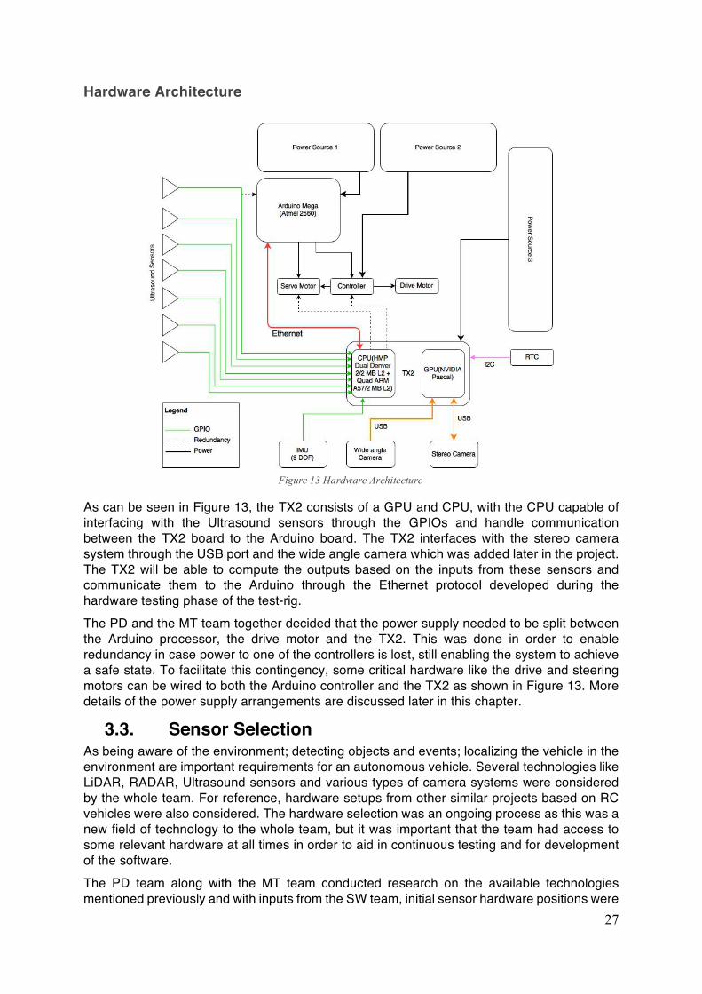
27
Hardware Architecture
As can be seen in Figure 13, the TX2 consists of a GPU and CPU, with the CPU capable of interfacing with the Ultrasound sensors through the GPIOs and handle communication between the TX2 board to the Arduino board. The TX2 interfaces with the stereo camera system through the USB port and the wide angle camera which was added later in the project. The TX2 will be able to compute the outputs based on the inputs from these sensors and communicate them to the Arduino through the Ethernet protocol developed during the hardware testing phase of the test-rig. The PD and the MT team together decided that the power supply needed to be split between the Arduino processor, the drive motor and the TX2. This was done in order to enable redundancy in case power to one of the controllers is lost, still enabling the system to achieve a safe state. To facilitate this contingency, some critical hardware like the drive and steering motors can be wired to both the Arduino controller and the TX2 as shown in Figure 13. More details of the power supply arrangements are discussed later in this chapter.
3.3. Sensor Selection As being aware of the environment; detecting objects and events; localizing the vehicle in the environment are important requirements for an autonomous vehicle. Several technologies like LiDAR, RADAR, Ultrasound sensors and various types of camera systems were considered by the whole team. For reference, hardware setups from other similar projects based on RC vehicles were also considered. The hardware selection was an ongoing process as this was a new field of technology to the whole team, but it was important that the team had access to some relevant hardware at all times in order to aid in continuous testing and for development of the software. The PD team along with the MT team conducted research on the available technologies mentioned previously and with inputs from the SW team, initial sensor hardware positions were
Figure 13 Hardware Architecture
28
decided. However, the most crucial decision for the team to take was whether to use LiDAR, RADAR or cameras. RADAR implementation was discarded as the available systems were expensive and it would be very difficult to mount on a 1:10 RC vehicle because the systems were large. It also needed some setup time to achieve a reliable functionality, hence the team collectively decided that with the time and budget available, RADAR system would not be viable.
Lidar vs Camera The decision between LiDAR and cameras was a decision that needed careful consideration. Based on the literature study LiDAR systems for scaled vehicles were not many and were expensive. The most feasible solution would provide a single channel of data delivering a point cloud along a single plane. Hence it was decided that a LiDAR system would not be suitable considering the project’s tight timeline and budget. Another consideration was that this project would result in two theses within the SW team, hence the decision to choose LiDAR or cameras would dictate the area of technical development the SW team would explore in their theses. Considering the aforementioned factor and the literature study carried out by the entire team, it was decided that choosing a camera system instead of a LiDAR system would benefit the SW team’s interest in using computer vision and AI. This decision was further supported by the fact that Tesla Motors, producing vehicles capable of high levels of autonomy, does not use a LiDAR system in their vehicle but used only cameras instead (Tesla, 2017). More companies such as AIMmotive (Baldwin, 2017) are also developing ADS that are based mainly on cameras and image processing algorithms. Another company called AutoX (2017) has developed a system that uses a combination of AI and mountable camera system to enable self-driving. In order to better understand if there could be any other combination of sensors to be used for object identification and localization a concept generation exercise was carried out.
Concept Generation Concept generation and evaluation was done in order to make sure no important aspects were missed in the definition of the sensor hardware, even though the technological product in question is not necessarily suited for typical matrix framework. The methodology followed the one proposed by (Almefelt, 2016), although modified to fit the specific needs of the project. A functional breakdown of the system was performed using a Function Means Tree as the starting point of concept generation.
Idea Generation Concept generation used a morphological matrix as support, where the header of each row was specified as a sub function, previously identified in a functional breakdown. Solutions were generated on each column for the individual sub functions during a brainstorming session between the PD and MT teams. The results of idea generation were quite diverse with interesting outcomes, with ideas ranging the whole spectrum from safe to eccentric. The brainstorming session was less than two hours long with a break at the halfway point.
Concept Synthesis Different sensor configurations were then synthesised into system-level concepts, by working through the morphological matrix. A peculiarity was that in this case, due to the relatively low number of functions, the participating PD and MT teams felt the need to choose multiple solutions to fulfil certain functions. The results of concept synthesis were a dozen combinations of possible solutions to achieve the given functions (functions which were simplified for the purpose of synthesising), however due to the complexity of functions that can be achieved as
29
a combination of hardware and software, this did not yield particularly useful results. Hence after attempting the concept generation as per methodology it was decided that it could not deliver the results that were needed.
Concept Evaluation With the generated concepts, key technologies that they featured were evaluated rather than the entire concept. The evaluation started with the selection of an evaluation method. Because the purpose of evaluation was to find the best sensor technologies to achieve the best system solution, the Pugh matrix was chosen as a support, as it is not strong screening method along with the fact that it’s easy and not tedious and hence seemed suited for the knowledge gained at that point. The following step was the definition of the evaluation criteria. To this end, some vital target product requirements that were developed at this stage, along with Pugh’s major elements of a specification (1990) were used to add completeness to the criteria. The best method found for evaluation was a simple matrix, where the desired use-case scenarios along with requirements and needs represented the rows. Each column represented a technical solution, from the ones previously established in the concept generation phase. All technologies considered were at this point studied and documented in pros and cons lists for easy referencing. The results of the evaluation are presented in Appendix E.
Results of Technology Evaluation The concepts that scored highest were cameras, with 3D and 2D cameras scoring maximum. In second place were stereo cameras, followed by structure cameras and LiDAR in fourth place. LiDAR costs exceeded the project budget however and had a steeper learning curve and was therefore eliminated. It is worth mentioning that although a FOV evaluation criteria was introduced, it only considered one instance of the respective sensor, due to the possibility of placing more than one sensor on the car. As the specifics of the test tracks were not decided, an initial positioning of the camera was assumed which helped in initiating development; later on, CAD models and simulations were used to evaluate the ideal positions for the two camera alternatives considered.
Hardware Setup With the Cameras being the clear choice considering the project goal, scope, budget and the results from the concept generation exercise, the next step was to choose the best camera system that would enable the intended functions. To achieve this, it was clear that the system needed to have stereoscopic capabilities. Several cameras were benchmarked and the ZED camera from Stereolabs was ideal for this project. Not only because it was a stereo camera with two RGB sensors enabling stereo vision up to 20 m and operation outdoors but it also had software support in the form of SDKs (Software Development Kits) hence being compatible with the Nvidia TX2 board. However due to lengthy delays in receiving the ZED camera, the team decided to employ an Intel Real sense R200 camera which was the next best product in the comparison carried out earlier. There was also adequate software support from Intel for operation with the TX2. The R200 system featured a single RGB camera and stereoscopic capabilities, the stereo vision system operated on infrared spectrum rather than visible light, hence unlike the ZED camera, it could not perceive depth information at long range. The PD team decided that the RC vehicle would drive at a maximum speed 7 km/h and correspondingly lower speeds for manoeuvres like parking or city driving. The regulation of the servo motor and the drive motor which controlled the vehicle’s lateral and longitudinal motion was developed by the MT team with some assistance from the PD team. For longitudinal control, the MT team developed a transfer function based on a PI controller to enable speed control. For the lateral control, they developed a system that linked the steering angle and the turning radius. They were also responsible for the sensor and hardware placement as well as the overall wiring scheme. A rudimentary manual override for use during development was
30
also implemented by the MT team, the specifics of which are detailed in the thesis by Jakobsson and Sundkvist (2017). As explained earlier in this chapter, three power sources would be needed to operate the prototype - one for the Arduino module, second for the motors and the third for the TX2 board. The battery capacity requirements for the prototype had to be determined; the MT team in collaboration with the PD team calculated the power requirements for the individual components. A run time of 30 mins for the prototype was targeted by the team, considering the prototype would be demonstrated at technical fairs. The Arduino is powered by a USB battery bank of 15600 mAh while the drive motors are powered by a Nickel Metal Hydrate (NiMH) battery pack with a capacity of 3000 mAh and the TX2 is powered by two 3000 mAh battery packs in parallel to provide the required capacity to last for approximately 30 minutes during operation. The limiting factor (bottleneck) for the vehicle’s endurance is the power source to the TX2.
3.4. Final Software Setup Software Development Environment The software development for the project was an important part of implementing functions. It was what utilized the hardware to achieve various ADS functionality. While the actual techniques and methods that were used for developing the software are not within the purview of this thesis, it was vital for the PD team to understand the development process and tools utilized for embedded software development. As mentioned earlier, the SW team split into two groups, Computer Vision Team and the other working on Decision Making. Gitlab was used as a code repository where different members of the software team could work on different parts of the code. It also helps in accessing code from written by other team members. The Gitlab package allowed for version management to ensure that functioning versions of overall code is always available. Gitlab also provides access to open source code to enable reuse of code hence making development more efficient.
Computer Vision The Computer Vision Team used video stream from the cameras as input to their code. Image processing techniques were applied using OpenCV toolbox. Several tools and filters were used for instance in implementing lane detection and training. The B-Snake (Yue Wanga, 2003) method was used to obtain the vehicle’s position on the centre of the lane. More details are available in the thesis by Posch and Rask (2017).
Decision Making As mentioned earlier, AI in the form of neural nets developed on deep learning algorithms were used. A simple neural net consists of several basic units called neurons which are processing units. Some neurons can be activated by data inputs from sensors (these neurons are called input neurons), others can be activated by weighted connections with the previous neurons and propagate their output to the next neuron. There can be neurons that directly influence the environment by outputting triggering actions (called output neurons). A deep neural net is a collection of several neurons of different types which are linked together by different layers to utilize the inputs from the environment to deliver output based on the weights to the environment (Schmidhuber, 2014). Depending on the problem and the connections of the neural nets, the chains of the network between neurons exhibit several computational stages. Learning or credit assignment is the process of determining the weights that make a neural net behave in a desirable manner. Further deep learning is a process of accurately assigning credit across all the stages of computing. (Schmidhuber, 2014).
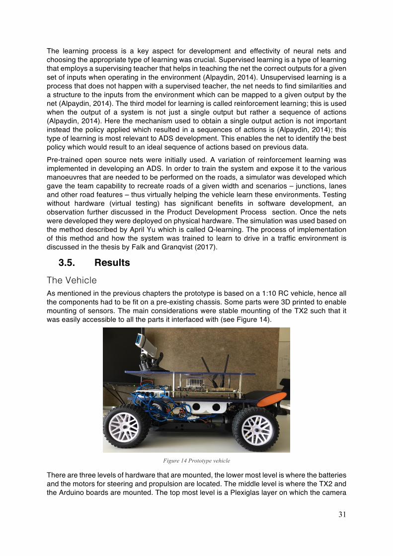
31
The learning process is a key aspect for development and effectivity of neural nets and choosing the appropriate type of learning was crucial. Supervised learning is a type of learning that employs a supervising teacher that helps in teaching the net the correct outputs for a given set of inputs when operating in the environment (Alpaydin, 2014). Unsupervised learning is a process that does not happen with a supervised teacher, the net needs to find similarities and a structure to the inputs from the environment which can be mapped to a given output by the net (Alpaydin, 2014). The third model for learning is called reinforcement learning; this is used when the output of a system is not just a single output but rather a sequence of actions (Alpaydin, 2014). Here the mechanism used to obtain a single output action is not important instead the policy applied which resulted in a sequences of actions is (Alpaydin, 2014); this type of learning is most relevant to ADS development. This enables the net to identify the best policy which would result to an ideal sequence of actions based on previous data. Pre-trained open source nets were initially used. A variation of reinforcement learning was implemented in developing an ADS. In order to train the system and expose it to the various manoeuvres that are needed to be performed on the roads, a simulator was developed which gave the team capability to recreate roads of a given width and scenarios – junctions, lanes and other road features – thus virtually helping the vehicle learn these environments. Testing without hardware (virtual testing) has significant benefits in software development, an observation further discussed in the Product Development Process section. Once the nets were developed they were deployed on physical hardware. The simulation was used based on the method described by April Yu which is called Q-learning. The process of implementation of this method and how the system was trained to learn to drive in a traffic environment is discussed in the thesis by Falk and Granqvist (2017).
3.5. Results The Vehicle As mentioned in the previous chapters the prototype is based on a 1:10 RC vehicle, hence all the components had to be fit on a pre-existing chassis. Some parts were 3D printed to enable mounting of sensors. The main considerations were stable mounting of the TX2 such that it was easily accessible to all the parts it interfaced with (see Figure 14).
Figure 14 Prototype vehicle
There are three levels of hardware that are mounted, the lower most level is where the batteries and the motors for steering and propulsion are located. The middle level is where the TX2 and the Arduino boards are mounted. The top most level is a Plexiglas layer on which the camera

32
is mounted. The ultrasound sensors are mounted on 3D printed carriers that mount on to the front and the rear parts of the RC vehicle chassis.
Figure 15 Prototype vehicle
Final Results and Validation At the time of completion of the thesis, the prototype could achieve one of the two minimum functions that were targeted. At the time of the completion of this thesis the prototype achieved lane keeping in a rudimentary stage with good lighting conditions. The function still needed refinement and fine tuning. These activities were slated to be carried out for another week of work on the prototype as scheduled by the team. In order to compensate for the lack of the wide angle FOV, another wide angle camera was purchased and mounted onto the vehicle, which helped in improving this function’s performance. This was a case wherein the platform that was selected made it easier to add extra hardware to enhance the functionality, hence proving that the platform selected was a capable one. The second function that was targeted was object recognition and ranging. This was however not achieved when this thesis ended. The hardware needed for this function was available and mounted on the vehicle but the software to implement this function was yet to be completed. Nonetheless, this was also scheduled to be completed in the remaining week after this thesis completed. There are two approaches considered by the team- one could be a solution using the depth information gathered from the R200 stereo camera or by using data from the ultrasound sensors, either data can be used to train the system. Fine tuning and validation of systems based on machine learning is still very unclear. The system needs to be exposed to more data and trained for achieving reliable performance. This however is not dealt much in this project but poses a big challenge to development in this field. Due to these facts and delays in acquisition of crucial components, it was not possible to achieve full functionality on all the three ODDs that were targeted. Instead the vehicle, at the end of the project could only achieve some basic functionality on the city ODD and the highway ODD however the parking ODD could not be achieved.
33
4. Development Process The scope of the project, defined and agreed upon by all eight project members as well as the project sponsor, intended the whole development process to follow agile methods. The main responsibilities of the thesis authors were to drive and manage the development process, in a chosen agile setting. A considerable amount of time was spent on this work aspect and this chapter presents the methodology for choosing an agile framework, its prescribed framework and implementation, the product development process, the project structure, along with management aspects and results from using the agile framework.
4.1. Lean and Agile Product Development Traditional Product Development Process “A product development process is the sequence of steps or activities that an enterprise employs to conceive, design, and commercialize a product” (Ulrich & Eppinger, 2012). Although the 1:10 scale vehicle in this project is not meant to be commercialised, Ulrich and Eppinger’s definition of a development process holds true for most products, be it physical products, or software. However, due to the nature of the product itself, the sequence of steps or activities can differ in the development of physical products or software products. Ulrich and Eppinger’s (2012) process flow diagram for complex systems development1 can be seen in Figure 16.
In the process proposed by Ulrich and Eppinger (2012), the concept development phase considers the system architecture definition, where multiple architectures may be considered for the system. In this phase, the decomposed sub-systems and their components are designed in parallel by different responsible teams and then integrated by yet another set of teams. The interactions between the different subsystems is managed by systems engineers of different specialties. In the testing and refinement phase, extensive testing and validation at all levels is included (Ulrich & Eppinger, 2012). The process outlined by Ulrich and Eppinger (2012) focuses on products that are engineered, discrete, and physical. A considerable challenge when working with physical products is of course costs involved in development, where cost of changes is higher the further down the timeline they are implemented. This places a demand on early exploration and knowledge building - one of the key principles in Lean Product Development (Mynott, 2012). Software development is characterised by lower costs of change and more constant costs over time, compared to hardware development (Cprime, 2015). This allows for greater agility to respond to changing needs and this has in effect spawned many agile ways of working. The traditional software development process - termed ‘waterfall’ process - leaves much to be desired in this case, with its sequential development phases. Deemer, Benefield, Larman, and 1 Disclaimer on Ulrich & Eppinger process: In no event shall McGraw-Hill Education have any liability to any party for special, incidental, tort, or consequential damages arising out of or in connection with the McGraw-Hill Education Material, even if McGraw-Hill Education has been advised of the possibility of such damages.
Figure 16 Complex system development process by Ulrich and Eppinger (2012), © McGraw-Hill Education
34
Vodde (2010) point out that there are many variants of ‘the waterfall’ process, but it is typical that projects that follow this type of development process start with a detailed planning phase, where the product is “designed, and documented in great detail” (Deemer et al., 2010). Responsible team members then do specialised work and upon completion, they pass it on to a testing organisation. The whole process is strictly monitored for deviations. The one weakness of this approach is that humans are involved, Deemer et al. (2010) point out. This type of process can stifle innovation, hinder communication by prioritising documentation over face-to-face discussions, not allowing good ideas to influence the project after the planning phase (Deemer et al., 2010). The pitfall of setting rigid requirements early on is that the product can only be as good as the initial idea. All these drawbacks, Deemer et al. (2010) argues, lead to a product that does not fully leverage the potential of its developers. One of the research questions posed by this thesis report stems from the need to integrate these two disciplines, in a high-technology product. What process can be used in the development of an ADS, comprising both hardware and software? Can agile methods be implemented in hardware development, or what are the adaptations needed? There is not yet a significant amount of literature available on the subject and this chapter aims to give a brief overview of said literature, as well as present the implementation of the agile method and its results in the development process of this project.
Agile and Lean Product Development in Theory Agile methods were born to counteract the drawbacks of the ‘waterfall’ process in traditional software development. Agile development is an iterative process that puts the focus on working software instead of early and rigid requirements specification, with work carried out in empowered cross-functional teams with continuous customer input (Deemer et al., 2010). The Agile Manifesto presents twelve agile principles. Its creators are representatives of various alternative agile software development processes - Extreme Programming, Scrum, Dynamic Systems Development Method, Adaptive Software Development, Crystal, Feature Driven Development, Pragmatic Programming, as well as others – (Highsmith, 2001). Summarised and adapted from (Highsmith, 2001), some of the most important Agile principles are stated below:
• Prioritise and deliver working software frequently
• Welcome changing requirements, harness change for the customer’s competitive advantage
• Daily collaboration between business people and developers
• Support and trust team
• Teams are self-organising
• Effective communication through face-to-face conversations
• Set a project pace which can be maintained indefinitely
• Simplicity
• Reflect and adjust The benefits of agile to the ADS development project were clear. Due to the high technical complexity of the product, the high levels of uncertainty involved and the lack of in-depth experience in the field of the team members, an iterative framework would allow for quick adjustments in the direction of the development process. As Agile principles have been used in software development, it is of interest to explore alternatives in the realm of physical products. For shorter time to market while maintaining high product quality, Lean Product Development proposes an alternative to the traditional product
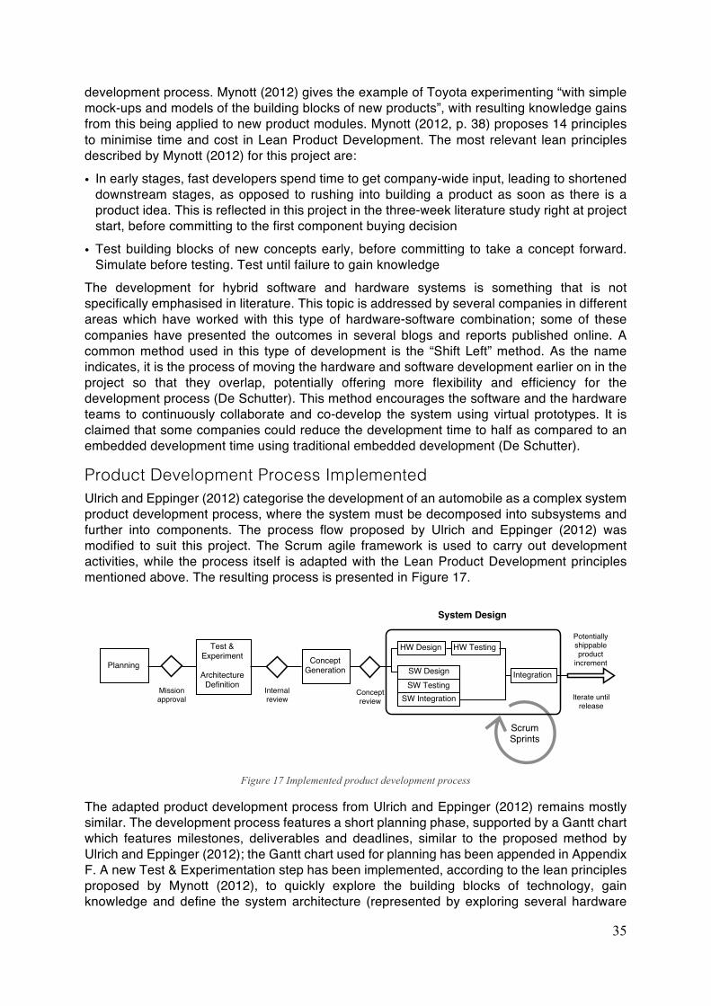
35
development process. Mynott (2012) gives the example of Toyota experimenting “with simple mock-ups and models of the building blocks of new products”, with resulting knowledge gains from this being applied to new product modules. Mynott (2012, p. 38) proposes 14 principles to minimise time and cost in Lean Product Development. The most relevant lean principles described by Mynott (2012) for this project are:
• In early stages, fast developers spend time to get company-wide input, leading to shortened downstream stages, as opposed to rushing into building a product as soon as there is a product idea. This is reflected in this project in the three-week literature study right at project start, before committing to the first component buying decision
• Test building blocks of new concepts early, before committing to take a concept forward. Simulate before testing. Test until failure to gain knowledge
The development for hybrid software and hardware systems is something that is not specifically emphasised in literature. This topic is addressed by several companies in different areas which have worked with this type of hardware-software combination; some of these companies have presented the outcomes in several blogs and reports published online. A common method used in this type of development is the “Shift Left” method. As the name indicates, it is the process of moving the hardware and software development earlier on in the project so that they overlap, potentially offering more flexibility and efficiency for the development process (De Schutter). This method encourages the software and the hardware teams to continuously collaborate and co-develop the system using virtual prototypes. It is claimed that some companies could reduce the development time to half as compared to an embedded development time using traditional embedded development (De Schutter).
Product Development Process Implemented Ulrich and Eppinger (2012) categorise the development of an automobile as a complex system product development process, where the system must be decomposed into subsystems and further into components. The process flow proposed by Ulrich and Eppinger (2012) was modified to suit this project. The Scrum agile framework is used to carry out development activities, while the process itself is adapted with the Lean Product Development principles mentioned above. The resulting process is presented in Figure 17.
Figure 17 Implemented product development process
The adapted product development process from Ulrich and Eppinger (2012) remains mostly similar. The development process features a short planning phase, supported by a Gantt chart which features milestones, deliverables and deadlines, similar to the proposed method by Ulrich and Eppinger (2012); the Gantt chart used for planning has been appended in Appendix F. A new Test & Experimentation step has been implemented, according to the lean principles proposed by Mynott (2012), to quickly explore the building blocks of technology, gain knowledge and define the system architecture (represented by exploring several hardware
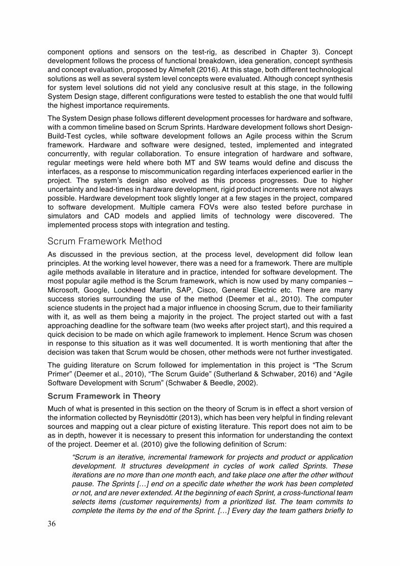
36
component options and sensors on the test-rig, as described in Chapter 3). Concept development follows the process of functional breakdown, idea generation, concept synthesis and concept evaluation, proposed by Almefelt (2016). At this stage, both different technological solutions as well as several system level concepts were evaluated. Although concept synthesis for system level solutions did not yield any conclusive result at this stage, in the following System Design stage, different configurations were tested to establish the one that would fulfil the highest importance requirements. The System Design phase follows different development processes for hardware and software, with a common timeline based on Scrum Sprints. Hardware development follows short Design-Build-Test cycles, while software development follows an Agile process within the Scrum framework. Hardware and software were designed, tested, implemented and integrated concurrently, with regular collaboration. To ensure integration of hardware and software, regular meetings were held where both MT and SW teams would define and discuss the interfaces, as a response to miscommunication regarding interfaces experienced earlier in the project. The system’s design also evolved as this process progresses. Due to higher uncertainty and lead-times in hardware development, rigid product increments were not always possible. Hardware development took slightly longer at a few stages in the project, compared to software development. Multiple camera FOVs were also tested before purchase in simulators and CAD models and applied limits of technology were discovered. The implemented process stops with integration and testing.
Scrum Framework Method As discussed in the previous section, at the process level, development did follow lean principles. At the working level however, there was a need for a framework. There are multiple agile methods available in literature and in practice, intended for software development. The most popular agile method is the Scrum framework, which is now used by many companies – Microsoft, Google, Lockheed Martin, SAP, Cisco, General Electric etc. There are many success stories surrounding the use of the method (Deemer et al., 2010). The computer science students in the project had a major influence in choosing Scrum, due to their familiarity with it, as well as them being a majority in the project. The project started out with a fast approaching deadline for the software team (two weeks after project start), and this required a quick decision to be made on which agile framework to implement. Hence Scrum was chosen in response to this situation as it was well documented. It is worth mentioning that after the decision was taken that Scrum would be chosen, other methods were not further investigated. The guiding literature on Scrum followed for implementation in this project is “The Scrum Primer” (Deemer et al., 2010), “The Scrum Guide” (Sutherland & Schwaber, 2016) and “Agile Software Development with Scrum” (Schwaber & Beedle, 2002).
Scrum Framework in Theory Much of what is presented in this section on the theory of Scrum is in effect a short version of the information collected by Reynisdóttir (2013), which has been very helpful in finding relevant sources and mapping out a clear picture of existing literature. This report does not aim to be as in depth, however it is necessary to present this information for understanding the context of the project. Deemer et al. (2010) give the following definition of Scrum:
“Scrum is an iterative, incremental framework for projects and product or application development. It structures development in cycles of work called Sprints. These iterations are no more than one month each, and take place one after the other without pause. The Sprints […] end on a specific date whether the work has been completed or not, and are never extended. At the beginning of each Sprint, a cross-functional team selects items (customer requirements) from a prioritized list. The team commits to complete the items by the end of the Sprint. […] Every day the team gathers briefly to
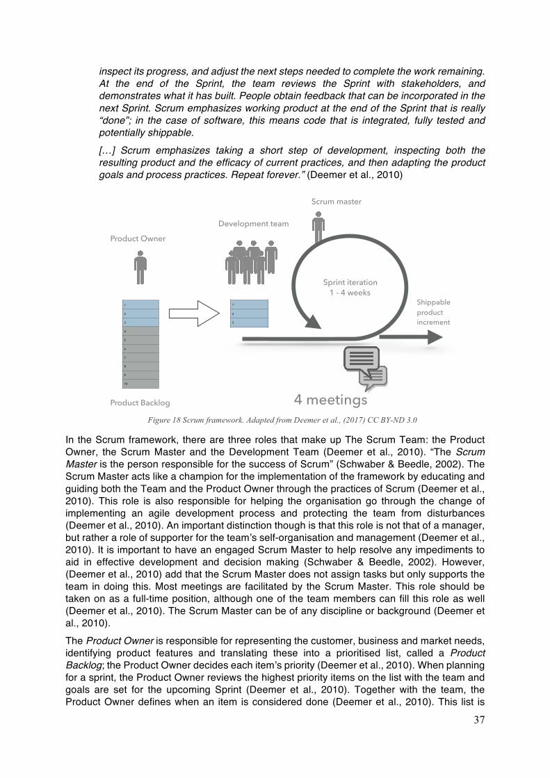
37
inspect its progress, and adjust the next steps needed to complete the work remaining. At the end of the Sprint, the team reviews the Sprint with stakeholders, and demonstrates what it has built. People obtain feedback that can be incorporated in the next Sprint. Scrum emphasizes working product at the end of the Sprint that is really “done”; in the case of software, this means code that is integrated, fully tested and potentially shippable. […] Scrum emphasizes taking a short step of development, inspecting both the resulting product and the efficacy of current practices, and then adapting the product goals and process practices. Repeat forever.” (Deemer et al., 2010)
In the Scrum framework, there are three roles that make up The Scrum Team: the Product Owner, the Scrum Master and the Development Team (Deemer et al., 2010). “The Scrum Master is the person responsible for the success of Scrum” (Schwaber & Beedle, 2002). The Scrum Master acts like a champion for the implementation of the framework by educating and guiding both the Team and the Product Owner through the practices of Scrum (Deemer et al., 2010). This role is also responsible for helping the organisation go through the change of implementing an agile development process and protecting the team from disturbances (Deemer et al., 2010). An important distinction though is that this role is not that of a manager, but rather a role of supporter for the team’s self-organisation and management (Deemer et al., 2010). It is important to have an engaged Scrum Master to help resolve any impediments to aid in effective development and decision making (Schwaber & Beedle, 2002). However, (Deemer et al., 2010) add that the Scrum Master does not assign tasks but only supports the team in doing this. Most meetings are facilitated by the Scrum Master. This role should be taken on as a full-time position, although one of the team members can fill this role as well (Deemer et al., 2010). The Scrum Master can be of any discipline or background (Deemer et al., 2010). The Product Owner is responsible for representing the customer, business and market needs, identifying product features and translating these into a prioritised list, called a Product Backlog; the Product Owner decides each item’s priority (Deemer et al., 2010). When planning for a sprint, the Product Owner reviews the highest priority items on the list with the team and goals are set for the upcoming Sprint (Deemer et al., 2010). Together with the team, the Product Owner defines when an item is considered done (Deemer et al., 2010). This list is
Sprint iteration 1 - 4 weeks
1
2
3
4
5
6
7
8
9
10
1
2
3
4 meetings
Product Owner
Product Backlog
Development team
Scrum master
Shippable product increment
Figure 18 Scrum framework. Adapted from Deemer et al., (2017) CC BY-ND 3.0
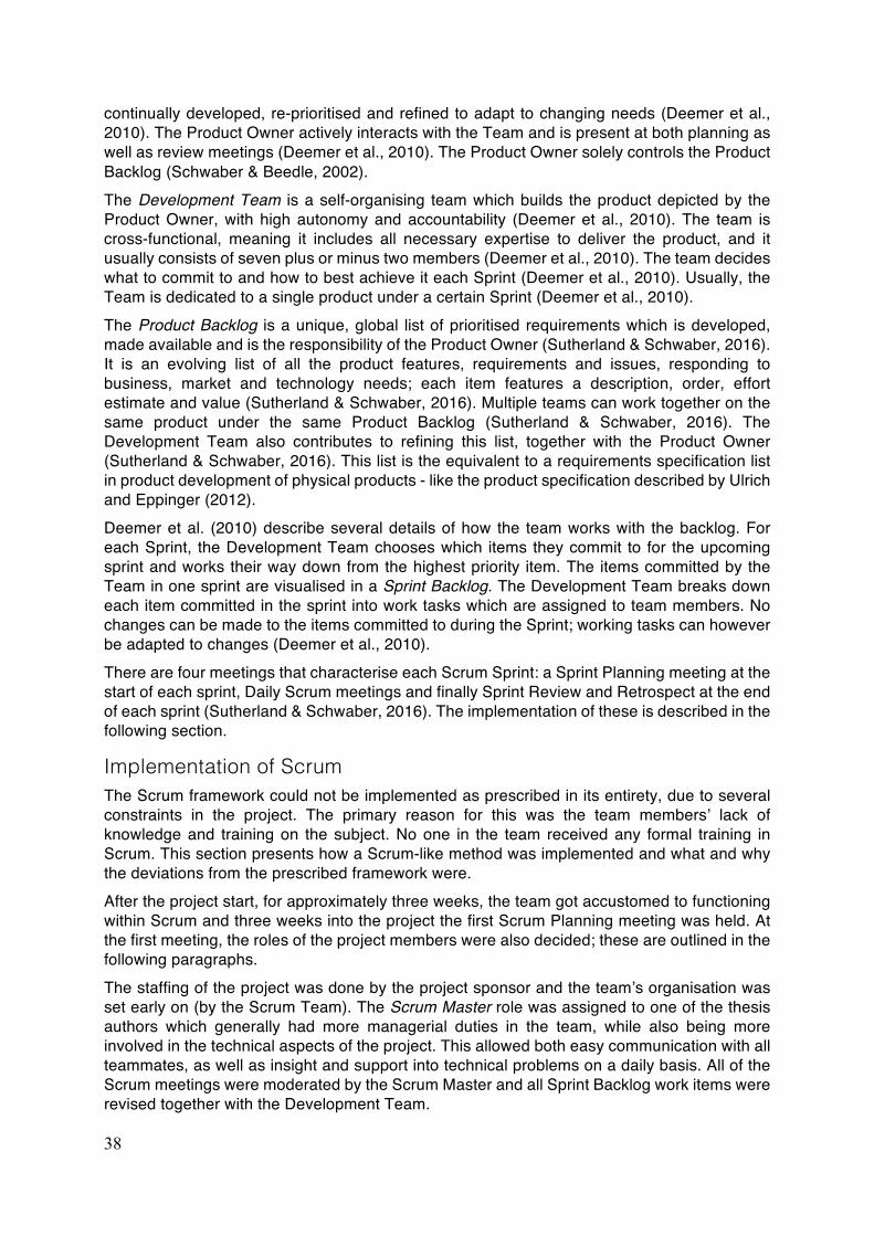
38
continually developed, re-prioritised and refined to adapt to changing needs (Deemer et al., 2010). The Product Owner actively interacts with the Team and is present at both planning as well as review meetings (Deemer et al., 2010). The Product Owner solely controls the Product Backlog (Schwaber & Beedle, 2002). The Development Team is a self-organising team which builds the product depicted by the Product Owner, with high autonomy and accountability (Deemer et al., 2010). The team is cross-functional, meaning it includes all necessary expertise to deliver the product, and it usually consists of seven plus or minus two members (Deemer et al., 2010). The team decides what to commit to and how to best achieve it each Sprint (Deemer et al., 2010). Usually, the Team is dedicated to a single product under a certain Sprint (Deemer et al., 2010). The Product Backlog is a unique, global list of prioritised requirements which is developed, made available and is the responsibility of the Product Owner (Sutherland & Schwaber, 2016). It is an evolving list of all the product features, requirements and issues, responding to business, market and technology needs; each item features a description, order, effort estimate and value (Sutherland & Schwaber, 2016). Multiple teams can work together on the same product under the same Product Backlog (Sutherland & Schwaber, 2016). The Development Team also contributes to refining this list, together with the Product Owner (Sutherland & Schwaber, 2016). This list is the equivalent to a requirements specification list in product development of physical products - like the product specification described by Ulrich and Eppinger (2012). Deemer et al. (2010) describe several details of how the team works with the backlog. For each Sprint, the Development Team chooses which items they commit to for the upcoming sprint and works their way down from the highest priority item. The items committed by the Team in one sprint are visualised in a Sprint Backlog. The Development Team breaks down each item committed in the sprint into work tasks which are assigned to team members. No changes can be made to the items committed to during the Sprint; working tasks can however be adapted to changes (Deemer et al., 2010). There are four meetings that characterise each Scrum Sprint: a Sprint Planning meeting at the start of each sprint, Daily Scrum meetings and finally Sprint Review and Retrospect at the end of each sprint (Sutherland & Schwaber, 2016). The implementation of these is described in the following section.
Implementation of Scrum The Scrum framework could not be implemented as prescribed in its entirety, due to several constraints in the project. The primary reason for this was the team members’ lack of knowledge and training on the subject. No one in the team received any formal training in Scrum. This section presents how a Scrum-like method was implemented and what and why the deviations from the prescribed framework were. After the project start, for approximately three weeks, the team got accustomed to functioning within Scrum and three weeks into the project the first Scrum Planning meeting was held. At the first meeting, the roles of the project members were also decided; these are outlined in the following paragraphs. The staffing of the project was done by the project sponsor and the team’s organisation was set early on (by the Scrum Team). The Scrum Master role was assigned to one of the thesis authors which generally had more managerial duties in the team, while also being more involved in the technical aspects of the project. This allowed both easy communication with all teammates, as well as insight and support into technical problems on a daily basis. All of the Scrum meetings were moderated by the Scrum Master and all Sprint Backlog work items were revised together with the Development Team.
39
The Product Owner role was taken up by the other author of this report, who also had responsibility for requirements specification (as product backlog items) and project planning. Together, the authors of this report were also involved in researching available technologies and giving input to hardware selection. The Development Team consisted of six members, four computer science students and two mechatronics students. The project sponsor is a manager at the company with relevant technical knowledge in the automotive industry in the field of embedded systems development, with direct line of access to the company’s senior management. All team members were co-located in the same office with on-site workspace. Purchasing was done through another manager at the company, with whom the Scrum Master interacted frequently. Figure 19 presents the Scrum Team’s structure.
Figure 19 Scrum team structure
Due to thesis work being conducted in pairs of two students at different study programmes and with different time schedules, three sub-teams had to be established: software (SW), mechatronics (MT) and product development (PD). From here on now, they are simply referred to as the SW, MT and PD teams. MT and SW teams furthermore had a liaison person, to further facilitate communication and integration. The Scrum Team is therefore similar to a heavyweight team structure, as described by Wheelwright and Clark (1992). The thesis authors (PD) were responsible for driving the development process through the agile framework, while supporting development with well documented hardware choices, budget and planning, and finally ensuring proper integration. The available human resource for the project can be seen in Project Timeline Figure 1. Sprint iterations were set up starting with the third project week, first time limited to one week, then two weeks in the central part of the project timeline and finally reducing sprint time to one week in the last month of development. The final sprint was two weeks long due to examination at Chalmers. In the Product Development Process section, the overall project plan with milestones, deadlines and deliverables is presented. The current section will now focus on the Sprint intervals (seen in Figure 20).
Figure 20 Scrum sprints timeline
One global Product Backlog was visualised using an online tool called Trello (seen in Figure 21). This was effectively the visualised version of the requirements list. Due to the project
Scru
m te
am Scrum Master
Product Owner
Development Team
MT (Mechatronics)
SW (Software)Computer Vision
Decision Making
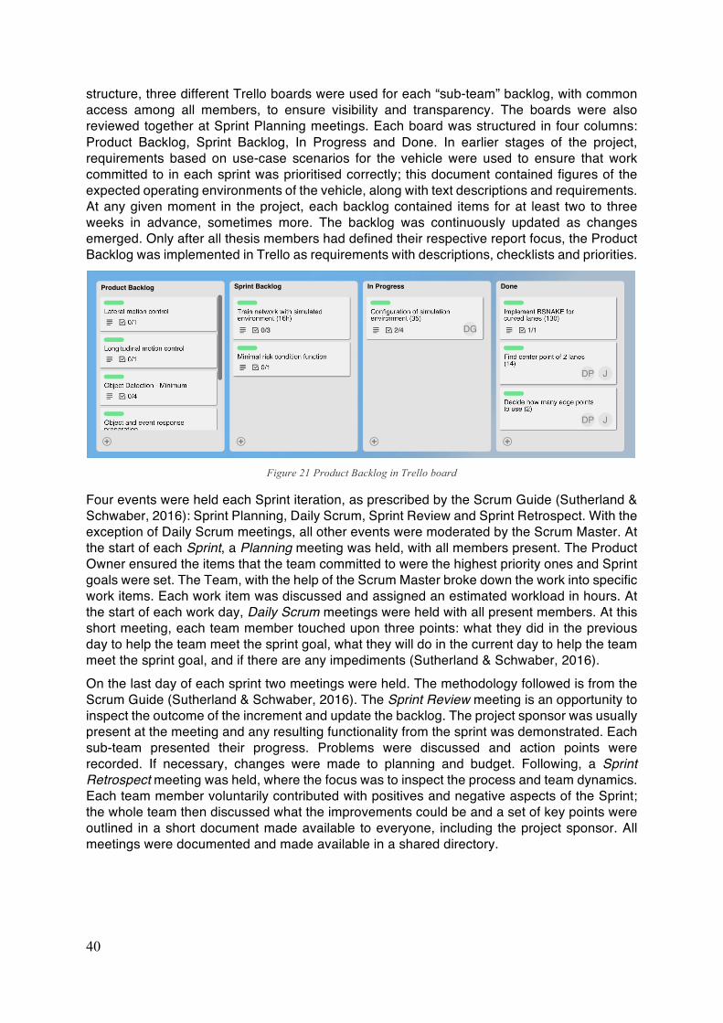
40
structure, three different Trello boards were used for each “sub-team” backlog, with common access among all members, to ensure visibility and transparency. The boards were also reviewed together at Sprint Planning meetings. Each board was structured in four columns: Product Backlog, Sprint Backlog, In Progress and Done. In earlier stages of the project, requirements based on use-case scenarios for the vehicle were used to ensure that work committed to in each sprint was prioritised correctly; this document contained figures of the expected operating environments of the vehicle, along with text descriptions and requirements. At any given moment in the project, each backlog contained items for at least two to three weeks in advance, sometimes more. The backlog was continuously updated as changes emerged. Only after all thesis members had defined their respective report focus, the Product Backlog was implemented in Trello as requirements with descriptions, checklists and priorities.
Figure 21 Product Backlog in Trello board
Four events were held each Sprint iteration, as prescribed by the Scrum Guide (Sutherland & Schwaber, 2016): Sprint Planning, Daily Scrum, Sprint Review and Sprint Retrospect. With the exception of Daily Scrum meetings, all other events were moderated by the Scrum Master. At the start of each Sprint, a Planning meeting was held, with all members present. The Product Owner ensured the items that the team committed to were the highest priority ones and Sprint goals were set. The Team, with the help of the Scrum Master broke down the work into specific work items. Each work item was discussed and assigned an estimated workload in hours. At the start of each work day, Daily Scrum meetings were held with all present members. At this short meeting, each team member touched upon three points: what they did in the previous day to help the team meet the sprint goal, what they will do in the current day to help the team meet the sprint goal, and if there are any impediments (Sutherland & Schwaber, 2016). On the last day of each sprint two meetings were held. The methodology followed is from the Scrum Guide (Sutherland & Schwaber, 2016). The Sprint Review meeting is an opportunity to inspect the outcome of the increment and update the backlog. The project sponsor was usually present at the meeting and any resulting functionality from the sprint was demonstrated. Each sub-team presented their progress. Problems were discussed and action points were recorded. If necessary, changes were made to planning and budget. Following, a Sprint Retrospect meeting was held, where the focus was to inspect the process and team dynamics. Each team member voluntarily contributed with positives and negative aspects of the Sprint; the whole team then discussed what the improvements could be and a set of key points were outlined in a short document made available to everyone, including the project sponsor. All meetings were documented and made available in a shared directory.
41
Deviations to Scrum Some deviations to the methods prescribed in the Scrum Guide (Sutherland & Schwaber, 2016) were made.
• Product Backlog in its final form was not made available by the Product Owner on the board until the start of May, just over a month away from project finish. This did not insure full visibility, thus not respecting one of the pillars of Scrum (Sutherland & Schwaber, 2016). A full backlog could not be developed from the onset, due to uncertainties with the project’s direction.
• Similarly, when deliverables existed for a specific sub-team to academic commitments at Chalmers, Product Backlog items were not specified by the Product Owner. The teams were however skilled in developing their own backlog items and in this case, the Product Owner only made sure that the items chosen were appropriate to the direction of the project.
• The Product Owner did not estimate value or effort for the Product Backlog items. Rather, the items were just prioritised and workload was estimated in an overall project Gantt chart.
• Defining the desired level of completion (‘definition of done’) for Sprint items was not explicitly agreed upon at the start of each Sprint in earlier stages of the project. This was due to very high uncertainty with the test rig and lack of knowledge from Product Owner and Scrum Master about the software intricacies.
• Some sprints did not follow the ‘shippable product increment’ principle. This was sometimes not possible for both teams.
• Development Team was split into three sub-teams according to study programme. This goes against the Scrum Guide (Sutherland & Schwaber, 2016), which states that “Scrum recognizes no sub-teams in the Development Team, regardless of particular domains that need to be addressed like testing or business analysis; there are no exceptions to this rule”. Similarly, accountability for the work was therefore held by the responsible sub-teams
• The Scrum Master did not always push the Product Owner or Development Team to follow the Scrum framework, when deviations occurred.
• Daily Scrum was not religiously followed. It was rather easy to overlook, due to the fluctuation of members’ presence in the office. Sometimes, PD team also took part in Daily Scrum, for the sake of transparency and to obtain an update on the status of the project.
• Some Review and Retrospect meetings were not held altogether, for example during exam periods when members were not present for a week or more in office. Some Sprint Reviews were postponed into the next sprint, when the project sponsor was available
• Monitoring sprint progress was sometimes vague. This was due to the Trello board not being updated regularly, but done only towards the end of a sprint. Halfway through the project, charts monitoring progress (burndown charts) were implemented for Trello, although they were not easy to access.
42
Results from Scrum Implementation This section presents the pros and cons as part of the Scrum implementation in this project. These results are compiled from documented Sprint Review and Retrospect meetings.
Pros • One benefit of working agile in short iterations was that due to high uncertainty, revising
plans and responding to change is essentially built into the process. This constant re-evaluation of the project direction allowed for late decisions on important matters (such as purchasing an expensive component), in order to adapt to new findings and choose the best hardware for the vehicle
• The Daily Scrum meetings were appreciated by everyone, as they provided transparency and prevented redundant work on the same item by different team members
• The Scrum meetings force people to collaborate and discuss face-to-face. This has been found to be a positive among team members, through observation and drawing inferences from Retrospects. Review and Retrospects furthermore allow for easy capturing of knowledge and lessons learned.
• The authors observed that co-location was beneficial in sparking discussion. When both SW and MT members were together in office, collaboration and integration was significantly improved.
Cons Not all meetings went according to plan. There were noticeable improvements into how the meetings were conducted at the start of the project, compared to the end. What has been presented reflects the latter, unless otherwise stated. From the collection stage (Maylor, 2010) of the team until full efficiency and effectiveness of the meetings was approximately three months. This process could have been accelerated with some training in using Scrum early on.
• During stressful times in the project when workload was high, taking time to hold all the meetings created tension. Team wanted to skip meetings and continue work
• Using one week sprints, the team’s commitments to deliverables were often not met and were easy to ‘push’ to another Sprint
• A common technical language among all team members was a problem, with the SW team in particular having difficulty in putting a clear technical point across. This can be due to the varied backgrounds and unfamiliarity of the rest of the team towards software intricacies and terminologies. Efforts were however made to ‘dumb down’ explanations as the project progressed and improvements were noticed
• It can take time to get accustomed to Scrum and be efficient and effective in work. Only by early March did the team report satisfaction with how Scrum was working. This could have also been due to lack of clarity early on with respect to test-rig
• Product Backlog was not refined together with the development team, only during Sprint Planning meetings. The team was somewhat reluctant to look outside their own work items in the backlog at times. This however improved once the Product Backlog was expressed more clearly, when team members reported in one of the final Retrospects that they know exactly what they need to do.
43
Project Management and Timeline The project was split into two halves, this was based on the study timings of the university and how the team needed to focus on different academic commitments. Hence the first half was used to form the team and get through the collection and entrenchment (Maylor, 2010) phases of team dynamics. The thesis authors (PD team) delved into the soft aspects by arranging team building activities such as team meets and after works to help the process of collection quicken. The work area was also considered and more white boards were ordered and installed to ensure that team members could more easily share, visualise and discuss ideas. Although most team members were Swedish speaking, English was decided as the main language for communication such that the PD team could also understand and contribute to the discussion if needed. However, when matters of specific technical details needed to be discussed the PD team encouraged the team members to convey it in Swedish in order to help ease the communication. The second half of the project used the knowledge and relationships built in the first half as a foundation to move forward. Actual development of the system was significantly shorter due to the different timeline of the other students involved in the project. The components procurement and the budget was managed by the PD team. Once a component to be purchased was identified, a request was raised to the PD team. The Scrum Master would then approach the company manager in charge of finances to make the purchase. The initial budget was set at 10000 SEK, but due to some setbacks (for example with one camera system being delayed) and general expenses in both project related as well as inventory purchases caused the budget to creep up to 11000 SEK. A request for raising the budget was made quite early on upon estimations from the PD team and the new budget was approved by the midpoint of the project.

44
45
5. Discussion & Future work 5.1. Discussion
On the outset, this was a broad project which was commissioned primarily to build knowledge about both technical and managerial aspects of developing an ADS. The outcome of the project is a consequence of this particular project structure, organization and timeline, along with the academic commitments of the various team members. This chapter will focus on the learnings and observations regarding these aspects and propose some suggestions based on these learnings to potentially improve the work flow for similar multidisciplinary projects. Finally, possible future tasks are suggested if the project is to be continued.
Project Management Co-location of the entire team was very useful, making discussions and collaboration easier. Co-location also facilitated in gauging the overall team morale and pace of working in order to plan ahead. Although the hardware procurement process was effective, easier access to project funds would have shortened component purchase lead times. The person responsible in the company was external to the team and at times, was difficult to contact. Although the procurement process became more efficient as the project progressed, vital purchase decisions at project start-up were affected.
SCRUM in Multidisciplinary Projects The decision to implement Scrum was taken because the SW team was familiar with the framework. Also, the project was software intensive, with none of the team members having experience in implementing any other agile method except for Scrum. Many available resources to facilitate learning and implementation also motivated this choice. However, the entire project team followed an adapted version of Scrum, as deviations to the prescribed methods had to be implemented in order to adapt the framework to this project’s needs. The nature of the project scope as prescribed by the company alongside academic requirements, further constrained implementation of the Scrum framework. The PD team which comprised of a Scrum Master and the Product Owner were affected in different ways. The Scrum Master could not dedicate his full time towards the role and the Product Owner’s role was also affected as not enough time could be dedicated to the Product Backlog. Prioritising backlog items was also an issue for the Product Owner, considering product ownership is equally distributed among all project members due to the academic requirements and learning interests of all the team members. Both PD team members were furthermore involved in day to day activities of the team and thus, the roles of Scrum Master and Product Owner became blurred at times. The ADS developed in this project is a first within the company. The new technology and dedicated project staff with a high level of autonomy is characteristic of advanced R&D projects (Wheelwright & Clark, 1992) carried out by a heavyweight team. For these type of projects, developing a complete Product Backlog from the outset is difficult and thus, it must evolve with the project. It was observed that with the high levels of uncertainty early on in the project, a relatively short-term Product Backlog functions better, as long as there are still milestones and deadlines until the planned product release. Knowledge gained during early phases will gradually contribute to a clearer product vision, when a more thorough version of the Product Backlog can be articulated. Regular backlog refinement as prescribed by Scrum will ensure responding to market, business and technology needs while integrating new knowledge and ideas. As the backlog evolved and knowledge gaps were closed, Scrum seemed to work better. This was also observed in a case study at Marel GRB conducted by (Reynisdóttir, 2013).
46
Regarding Sprint lengths, a question arises as to whether shorter sprints lead to delays in the schedule, in high uncertainty situations. Due to the uncertainty, there were often commitment issues towards completion of tasks, especially within the SW team during a one-week sprint. Although the decision to keep sprints at one week in times of high uncertainty was taken to minimise risk and be flexible to changes, it might have affected the process in an unexpected way – delays in schedule due to unforeseen problems. There were some aspects that worked according to the recommended Scrum methodology. One such instance was that the Scrum Master being hands on and involved with the team. This helped in resolving obstacles encountered by the team, while also aiding in collaboration and integration. A further benefit observed with this arrangement, is the ability to provide technical feedback when demanded by team members. Due to the lack of experience amongst the entire team in the field of ADS, it was difficult to make informed decisions during the beginning of the project. This led to lack of clarity early in the project hence making it difficult for the team to be productive during this phase. It was also difficult to set achievable goals for each sprint in the early stages of the project. With the above critical prerequisite observed in this project, successfully implementing Scrum in a Development Team consisting of members with various backgrounds requires the use of common language and an openness and willingness to work towards the system solution.
Development Process The ADS as discussed in the previous chapters is predominantly a software driven product, however there is strong dependency on hardware. It was important that the SW team understood the method of hardware development and realized its limitations due to dependency on external factors. It took more than half of the project for this to occur; furthermore, this issue was compounded by the fact that the MT team, due to other academic commitments worked only half time for the whole of project as compared to the SW team which initially worked half time but switched to working full-time for the second half of the project. This resulted in a difference in pace between the two teams which caused some anxiety and misunderstandings. The adapted product development process worked well in this project setting. The common timeline of the MT and SW teams facilitated by Scrum was beneficial in advancing development and ensuring proper integration. The separate processes for the two teams in the System-level design stage allowed both integration of the different functions within the SW team as they were developed, along with actual implementation of these functions on the vehicle completed by the MT team. The heavyweight team organisation with liaisons also had benefits in interfacing the hardware and software parts of the product. Cprime (2017) suggests hybrid software and hardware projects follow a similar approach, with concurrent work done by a software team working with Scrum and a hardware team working with Constraint Based Project Management. The latter process identifies critical milestones in the project and plans both teams’ work accordingly (Cprime, 2017). Software is at times developed and tested independently of hardware. This method can be supported by what was observed in this project, as forcing the MT team to operate within the same Scrum timeline as the SW team proved difficult during the initial stages of the project. The effectiveness of the MT team improved in later stages when they committed to deliverables aligning to a particular date that was based on the SW team’s projected sprint progress. Requirements management proved difficult, due to technical complexity and the multiple levels of detail needed for the various system, subsystems and components of the vehicle. This is reflected as well by Davies (2004), who raises a similar question, by asking whether an item is a user requirement, a system requirement or a design specification. This lack of context clarity with respect to requirements is also discussed by Almefelt (2005).
47
Technical Discussion The most important takeaway from the technology used in this ADS development project was the use of camera technology to fulfil key ADS requirements. Cameras do not require much setup preparations as compared to RADAR or LiDAR system. They are also well supported in terms of software, as computer vision is a field that is used for several other applications hence there is strong open source support in this aspect. Cameras are relatively cheap and easy to replace or service if needed and they do not have any constantly moving parts ensuring longevity. Considering the current high price of LiDAR systems and buyers’ unwillingness to pay a big premium for self-driving features (in 2014), cheaper alternatives such as camera based systems, could have yet another benefit over the more expensive LiDAR. The prototyping strategy used in the initial stages of the project is a topic of discussion. As detailed in Chapter 3, in the first half of the project a test rig was developed to gain knowledge of the basic hardware for ADS development. The test-rig helped the team in gaining knowledge and understanding some areas of hardware and software development. However, if there would have been a clear and early decision to utilize image processing and neural nets as the basis for ADS development, some part of the first half of the project could have been used to simulate the virtual driving model, along with investigation and experimentation of image processing and neural networks. This could have helped the team achieve more functions. The area of validation of a machine learning based systems was not clear to the team. The use of machine learning in the project also posed the PD team with challenges to define requirements and validate them. The reasons for this was that the PD team had no experience in this field; furthermore, the field of machine learning being a rapidly advancing and changing field, there is a lack of general information available in this area. Hence the basic functions that were - and in the future - can be achieved on the prototype need to be validated to accepted levels. The lack of clarity in validation of these type of systems in on-road vehicles raises ethical questions as to the safety of ADS based on machine learning.
Recommended Improvements to Implemented Product Development Process Some recommendations to optimize development process for a project which consists of an interdisciplinary team trying to develop a system that is advanced and complex such as an ADS using agile methodology can be discussed. Based on the Sprint Retrospects, a few valuable improvement proposals that positively affected the process are outlined below:
• Have clear agenda for project sponsor meetings. Use this time efficiently
• Training the Scrum Team, especially the Scrum Master, in implementing the framework would be useful, as the Scrum Master can educate the rest of the team in using the framework and reaching productivity early on in the project
• Keep up with Daily Scrum. This was frequently mentioned in the Retrospects, which stated that this would improve transparency. On few occasions, it was observed it eliminated overlapping work within the respective teams. All Scrum meetings are important to flag problems early
• Clear deadlines will help in orienting the team towards common goals. Bringing awareness to the fact that hardware involves longer lead times
• Commit to speaking one common language, with which all team members feel comfortable with. Furthermore, effort to establish a common technical language is required for good collaboration
48
• Consider and plan interfaces and integration. One possibility would be to assign an interface responsible within the team. This was attempted in this project, but a lack of communication between the two leads decreased effectiveness of this effort
• As there were significant schedule mismatches between the different sub-teams, frustration surfaced due to lack of face-to-face discussion. Work was improved for everyone when more time was spent together in the office
• Team social events outside the office are important for team building
• Virtual prototyping and early hardware experimentation would expedite development process, by contributing to a more decisive hardware selection.
5.2. Future work The path towards a complete ADS is long and needs a lot of dedicated development and fine-tuning of systems in the prototype. To enable this the processing platform chosen in this project is expandable to enable continuation of work if pursued. The neural nets are mathematically validated currently based on the training model which runs mainly on data from the simulated games. The functions that are implemented currently need to be tested and validated on tests both in physical and simulated environments. As mentioned in Chapter 3 (Figure 13 Hardware Architecture), indicating some hardware redundancy is possible if the Arduino, TX2 and certain sensors are wired together. However, in order to implement this completely, supporting software to enable redundancy has to be coded, implemented and tested. Redundancy can be further developed for the power systems, where different battery systems can be accessed by other systems if in case there is a battery failure in any one system. Implementation of a LiDAR system could also be looked into in order to obtain more information about the surroundings. This would enable the RC vehicle to operate in the dark and low visibility conditions. This extra data could also be useful for the system to perform better in conditions when there are several moving objects in the vicinity of the vehicle. More camera systems with varying FOVs would also help to gain more information about the surroundings and increase the performance of existing systems. Although there was a user study in the form a focus group and some interviews were carried out in the project, more such focus groups and interviews of key stakeholders need to be carried out to gain a better understanding of their needs. These studies will also show how their views compare to the rules and regulations imposed on autonomous vehicles which are changing rapidly. The team developed a manual override in terms of the modified RC controller, in order for the vehicle to be used in a technical fair and in general to replicate the vehicle controls. It is however necessary to consider how the vehicle would be used in a fair environment, hence an app considering these requirements should be developed to operate the vehicle using a smart device for these situations. This app would be used as feedback and control method for the user and would aid in communicating the state of the vehicle as to whether, how and when the vehicle would hand over control to and from the user. The app could also convey important information such as battery levels and approximate time of operation for the vehicle, along with other interesting information such as distances to objects when being used in a manual mode etc. It would also enable the user to select start functions such as parking.
49
6. Conclusion In this project’s multidisciplinary setting, a lean product development process was followed for the Development Team. This process was adapted from Ulrich and Eppinger (2012) for developing complex products. The development process follows a more or less regular sequence of steps, where development work is undertaken within an Agile framework. A Scrum-like framework was implemented and co-located members of the Development Team conducted work in common sprints iterations. By doing this, development activities between the mechatronics and software teams were managed within a common timeline, while providing a setting for communication with frequent face-to-face discussions to facilitate collaboration. The Scrum framework further facilitates transparency and allows for flexibility in steering the project’s direction, through regular Sprint Planning meetings and Product Backlog refinement, thus ensuring response to change. A successful implementation of the Scrum framework in this project meant commitment from all team members. The Development Team needs an understanding of the product vision and must communicate dependencies and timelines to maintain a common pace (software and mechatronics teams) and be willing to work towards an optimal system solution. Mutual awareness of limitations in the other team’s working area will further facilitate a smooth operating Development Team. Common language among the project team is also of great importance. The Product Owner can only function effectively and drive the development process by having product vision and the Scrum master being involved hands-on. Scrum members reported improvements in working practices once knowledge was built (early on) and a clearer product direction could be formed. The recommendation of the thesis authors for similar projects is to organise the project in a Heavyweight team (according to Wheelwright and Clark (1992)) working within the Scrum framework and following a lean product development process. It is worth noting that some of the problems encountered in this project would probably have been avoided if the team members were not committed to academic and professional work external to the company project. The effectiveness of the process would have increased if the Product Owner and Scrum Master were more familiar with software development. Cameras were found to be a suitable technology in the development of highly automated driving. The underlying core function of Object and Event Detection and Response and its requirements were found to be satisfied in most situations by using cameras, in comparison with other sensor technologies like LiDAR and Radar. The resulting vehicle from this project was developed to a stage where it could achieve lane keeping and potentially automatic emergency braking in the relatively short duration. Early testing to understand the building blocks helped the team in selecting a strong platform for future development of the prototype. The final cost of this prototype was under 11,000 SEK. There are some questions with respect to validation of artificial intelligence systems, due to which, it was difficult to specify a ‘definition of done’ for backlog items that were executed with neural networks. This, as well as testing and validation of the system’s performance against the desired functional requirements need to be carried out. Out of the targeted three operating environments (ODD), the prototype had limited functionality on the city and highway ODDs while the parking ODD could not be achieved.

50
51
7. References AASHTO. (2001). A Policy on Geometric Design of Highways and Streets.
Albright, J., Bell, A., Schneider, J., & Nyce, C. (2015). Marketplace of change: Automobile insurance in the era of autonomous vehicles. Retrieved from https://assets.kpmg.com/content/dam/kpmg/pdf/2016/06/id-market-place-of-change-automobile-insurance-in-the-era-of-autonomous-vehicles.pdf
Almefelt, L. (2005). Requirements-Driven Product Innovation: Methods and Tools Reflecting Industrial Needs. (PhD), Chalmers University of Technology, Göteborg, Sweden.
Almefelt, L. (2015). Lecture on Design Methodology: Requirements Specification - Methods, guidelines, applications. In. Gothenburg, Sweden: Chalmers University of Technology.
Almefelt, L. (2016). Lecture on Systematic Design. In: Chalmers University of Technology.
Almefelt, L., Andersson, F., Nilsson, P., & Malmqvist, J. (2003). Requirements Management in Practice - Findings from an Empirical Study in the Automotive Industry. Journal of Research in Engineering Design.
Alpaydin, E. (2014). Introduction to Machine Learning.
April Yu, R. P.-S., Rishi Bedi. Deep Reinforcement Learning for Simulated Autonomous Vehicle Control.
AutoX. (2017, 2 June 2017). Retrieved from http://autox.ai/
Baldwin, R. (2017, 12 May 2017). Self-driving cars could soon be cheaper and easier to build. Retrieved from https://www.engadget.com/2017/05/12/self-driving-cars-could-soon-be-cheaper-and-easier-to-build/
Bertoncello, M., & Wee, D. (2015). Ten ways autonomous driving could redefine the automotive world. Retrieved from McKinsey&Company Automotive & Assembly website: http://www.mckinsey.com/industries/automotive-and-assembly/our-insights/ten-ways-autonomous-driving-could-redefine-the-automotive-world
Brandl, O. (2016). V2X traffic management.
Brewer, C. (2017, March 8, 2017). Putting the “car” in self driving cars - Ford Motor company-Meduim. Retrieved from https://medium.com/@ford/putting-the-car-in-self-driving-cars-5d0280eda99a
Consumer Reports. (2017, 26th April 2017). Cars With Advanced Safety Systems: Detailed list of cars with features that help drivers avoid or mitigate collisions. Retrieved from http://www.consumerreports.org/car-safety/cars-with-advanced-safety-systems/
Cprime. (2015, 19th November 2015). Hardware vs. Software Development: Similarities and Differences. Retrieved from https://www.cprime.com/2015/11/hardware-vs-software-development-similarities-and-differences/
52
Cprime. (2017). Challenges of Adopting Agile in Combined Hardware and Software Environments. Retrieved from https://www.cprime.com/2012/08/challenges-of-adopting-agile-in-combined-hardware-and-software-environments/
Davies, P. (2004). Ten Questions to Ask Before Opening the Requirements Document. Paper presented at the INCOSE 2004, Toulouse, France.
Deemer, P., Benefield, G., Larman, C., & Vodde, B. (2010). The Scrum Primer: version 1.2. Retrieved from goodagile website: http://goodagile.com/scrumprimer/scrumprimer.pdf
Deemer, P., Benefield, G., Larman, C., & Vodde, B. (2017). Scrum Overview Picture. In https://creativecommons.org/licenses/by-nd/3.0/deed.en_US (Ed.). http://scrumprimer.org/: Scrum Primer.
Deloitte. (2014). Global Automotive Consumer Study: Exploring consumers’ mobility choices and transportation decisions. Retrieved from Deloitte: https://www2.deloitte.com/us/en/pages/manufacturing/articles/automotive-trends-millennials-consumer-study.html
Deloitte. (2017). What’s ahead for fully autonomous driving. Consumer opinions on advanced vehicle technology: Perspectives from Deloitte’s Global Automotive Consumer Study. Retrieved from Deloitte: https://www2.deloitte.com/content/dam/Deloitte/us/Documents/manufacturing/us-manufacturing-consumer-opinions-on-advanced-vehicle-technology.pdf
Diamandis, P. (2014). Self-driving Cars are Coming. Retrieved from https://www.forbes.com/sites/peterdiamandis/2014/10/13/self-driving-cars-are-coming/ - 7ba224654b86
Dubey, A. (2016). Stereo Vision - Facing the challenges and seeing the opportunities for ADAS applications.
Eugensson, A. (2016). Overview of Regulations for Autonomous Vehicles. Retrieved from https://www.chalmers.se/en/areas-of-advance/Transport/calendar/initiative-seminar-2016/Documents/JanHellaker.pdf
Falk, A., & Granqvist, D. (2017). Combining Deep Learning with traditional algorithms in autonomous cars. Chalmers University of Technology, Gothenburg, Sweden. Retrieved from http://publications.lib.chalmers.se/records/fulltext/251868/251868.pdf
Falk Salewski, S. K. (2007). Hardware Platform Design Decisions in Embedded Systems - A Systematic Teaching Approach. ACM SIGBED Review - Special issues on the second workshop on embedded system education (WESE), 4(1).
Gartner. (2017). Top Trends in the Gartner Hype Cycle for Emerging Technologies, 2017. Retrieved from https://www.gartner.com/smarterwithgartner/top-trends-in-the-gartner-hype-cycle-for-emerging-technologies-2017/
Hannon, E. M., Colin; Orlandi, Itamar; Ramkumar Surya. (2016). An integrated perspective on the future of mobility. Retrieved from http://www.mckinsey.com/business-functions/sustainability-and-resource-productivity/our-insights/an-integrated-perspective-on-the-future-of-mobility
53
Hawkins, A. J. (2017, Feb 21, 2017). Uber’s self-driving cars are now picking up passengers in Arizona. Retrieved from https://www.theverge.com/2017/2/21/14687346/uber-self-driving-car-arizona-pilot-ducey-california
Highsmith, J. (2001). The Agile Manifesto. Retrieved from http://agilemanifesto.org/history.html
Hillary Abraham, C. L., Samantha Brady, Craig Fitzgerald, Bruce Mehler, Bryan Reimer, & Joseph F. Coughlin. (2016). Autonomous Vehicles, Trust, and Driving Alternatives: A survey of consumer preferences.
Hull, D. (2017, February 10, 2017). Ford Investing $1 Billion in Startup Founded By Two Autonomous Car Pioneers. Retrieved from https://www.bloomberg.com/news/articles/2017-02-10/ford-investing-1-billion-in-ex-google-uber-engineers-startup
Isaksson, O., Kossmann, M., Bertoni, M., Eres, H., Monceaux, A., Bertoni, A., . . . Zhang, X. (2013). Value-driven design : a methodology to link expectations to technical requirements in the extended enterprise. Paper presented at the INCOSE International Symposium, Philadephia, PA. http://bth.diva-portal.org/smash/record.jsf?aq2=%5B%5B%5D%5D&c=31&af=%5B%5D&searchType=SIMPLE&query=bertoni&language=sv&pid=diva2%3A834509&aq=%5B%5B%5D%5D&sf=all&aqe=%5B%5D&sortOrder=author_sort_asc&onlyFullText=false&noOfRows=50&dswid=-7634
Issakov, V. (2010). Microwave Circuits for 24 GHz Automotive Radar in Silicon-based Technologies. 5-17. doi:10.1007/978-3-642-13598-9
Jakobsson, A., & Sundkvist, A. (2017). Controllers and their implementation for an autonomous vehicle. Chalmers University of Technology, Gothenburg, Sweden. Retrieved from http://studentarbeten.chalmers.se/publication/251933-controllers-and-their-implementation-for-an-autonomous-vehicle
Jonas, A., Byrd, S. C., Shanker, R., & Ono, M. (2014). Nikola’s Revenge: TSLA’s New Path of Disruption. Retrieved from linkback.morganstanley.com/.../ss0v172s-3ost-g000-b2bf-984be168e301?...
Joy Frechtling, L. S. (1997). User-Friendly Handbook for Mixed Method Evaluations.
Keith Naughton, M. B. (2017, January 8, 2017). Alphabet’s Waymo Cuts Cost of Key Self-Driving Sensor by 90%. Retrieved from https://www.bloomberg.com/news/articles/2017-01-08/alphabet-s-waymo-cuts-cost-of-key-self-driving-sensor-by-90
Krafcik, J. (2016). Say hello to Waymo: what’s next for Google’s self-driving car project.
Lewis M. Clements, K. M. K. (2017). ECONOMIC EFFECTS OF AUTOMATED VEHICLES.
Lunden, I. (2017, Mar 13, 2017). Intel buys Mobileye in $15.3B deal, moves its automotive unit to Israel. Retrieved from https://techcrunch.com/2017/03/13/reports-intel-buying-mobileye-for-up-to-16b-to-expand-in-self-driving-tech/
Maylor, H. (2010). Project Management (Fourth ed.): Pearson.
54
McCormick, R. (2017, May 14, 2017). Lyft and Waymo are working together on self-driving car tech. Retrieved from https://www.theverge.com/2017/5/14/15639642/lyft-waymo-self-driving-car-partnership).
Mynott, C. (2012). Lean Product Development: A manager's guide: Institution of Engineering and Technology.
Federal Automated Vehicles Policy, (2016).
NHTSA. (2017). Laws and Regulations. Retrieved from https://www.nhtsa.gov/laws-regulations
Nikon. (2017). Nikon Lens Simulator.
Nordevall, J. (2015). Method Development of Automotive Ultrasound Simulations.
Nvidia. (2017). Retrieved from http://www.nvidia.com/object/what-is-gpu-computing.html
Philippe Bonnifait, M. J. a. V. r. C. (2007). Autonomous Navigation in Urban Areas using GIS-Managed Information.
Pillath, S. (2016). Automated vehicles in the EU: Briefing. European Parliamentary Research Service Retrieved from http://www.europarl.europa.eu/RegData/etudes/BRIE/2016/573902/EPRS_BRI(2016)573902_EN.pdf.
Posch, D., & Rask, J. (2017). A model based approach to lane detec- tion and lane positioning using OpenCV. Chalmers University of Technology, Gothenburg, Sweden. Retrieved from http://studentarbeten.chalmers.se/publication/250038-a-model-based-approach-to-lane-detection-and-lane-positioning-using-opencv
Pugh, S. (1990). Total Design: Integrated Methods for Successful Product Engineering. Wokingham, UK: Addison-Wesley.
Regeringskansliet. (2017). Regeringen banar väg för självkörande fordon [Press release]. Retrieved from http://www.regeringen.se/pressmeddelanden/2017/04/regeringen-banar-vag-for-sjalvkorande-fordon/
Reynisdóttir, Þ. r. s. (2013). Scrum in Mechanical Product Development: Case Study of a Mechanical Product Development Team using Scrum. (Master of Science Master’s thesis), Chalmers University of Technology, Gothenburg, Sweden.
SAE. (2016). J3016 Taxonomy and Definitions for Terms Related to Driving Automation Systems for On-Road Motor Vehicles. In: SAE International.
Schmidhuber, J. (2014). Deep learning in neural networks: An overview.
Schwaber, K., & Beedle, M. (2002). Agile software development with scrum. Upper Saddle River, NJ: Pearson Education International.
Shapiro, D. (2017, 16th March 2017). NVIDIA and Bosch Announce AI Self-Driving Car Computer. Retrieved from https://blogs.nvidia.com/blog/2017/03/16/bosch/
55
Sigma. (2017). Sigma Technology. Retrieved from http://sigmatechnology.se/
Silberg, G., & Wallace, R. (2012). Self-driving cars: The next revolution. Retrieved from https://faculty.washington.edu/jbs/itrans/self_driving_cars%5B1%5D.pdf
Singh, S. (2015). Critical Reasons for Crashes Investigated in the National Motor Vehicle Crash Causation Survey.
Sony. (2017). Sony Commercializes the Industry's First High-Sensitivity CMOS Image Sensor for Automotive Cameras, Delivering Simultaneous LED Flicker Mitigation and High-Quality HDR Shooting.
Strategy Analytics. (2017). Accelerating the Future: The Economic Impact of the Emerging Passenger Economy. Retrieved from https://newsroom.intel.com/newsroom/wp-content/uploads/sites/11/2017/05/passenger-economy.pdf
Sutherland, J., & Schwaber, K. (2016). The Scrum Guide: The Definitive Guide to Scrum: The Rules of The Game. Retrieved from Scrum Guides website: http://www.scrumguides.org/
Taranovich, S. (2016). Autonomous automotive sensors: How processor algorithms get their inputs.
Tesla. (2017). Retrieved from https://www.tesla.com/autopilot
Texas Instruments. (2015). Advanced Driver Assistance Systems (ADAS) Guide 2015. In. https://uk.farnell.com/wcsstore/ExtendedSitesCatalogAssetStore/cms/asset/images/europe/common/applications/automotive/pdf/ti-adas-solution-guide.pdf.
Ulrich, K. T., & Eppinger, S. D. (2012). Product Design and Development, Fifth Edition: McGraw-Hill Education.
Underwood, G. R. a. D. J. a. J. (2015). Radar Sensing for Intelligent Vehicles in Urban Environments. Sensors.
UNECE. (2016, 23rd March 2016). UNECE paves the way for automated driving by updating UN international convention. Retrieved from http://www.unece.org/info/media/presscurrent-press-h/transport/2016/unece-paves-the-way-for-automated-driving-by-updating-un-international-convention/doc.html
Wheelwright, S. C., & Clark, K. B. (1992). Revolutionizing Product Development: Quantum Leaps in Speed, Efficiency, and Quality. New York: The Free Press.
Williams, L. (2012). What agile teams think of agile principles. Commun. ACM, 55(4), 71-76. doi:10.1145/2133806.2133823
Yamauchi, B. (2010). All-Weather Perception for Man-Portable Robots Using Ultra-Wideband Radar.
Yue Wanga, E. K. T., Dinggang Shenb. (2003). Lane detection and tracking using B-Snake.
56
Appendix A – Requirements List 1/3
NrNeed
Category Justification1 Regulations
Follow reasonable etiquette AV Policy guidanceADS must be able to be switched off by user Revised Vienna ConventionDocument development process NHTSA AV guidance
Document process and procedures for assessment, testing and validation of system's capabilities
AV Policy guidance
Document process for assessment, testing and validation of OEDR capabilities
AV Policy guidance
Document process for assessment, testing and validation of behavioural competencies applicable for HAV
AV Policy guidance
Document process for assessment, testing and validation of crash avoidence capabilities and design choices
AV Policy guidance
Document process for transitioning to a minimal risk condition when a problem is encountered
AV Policy guidance
Document process for assessment, testing and validation of fall back approaches
AV Policy guidance
Collect , store and analyse event, incident and crash data, as well as positive outcomes AV Policy guidanceEvaluate and validate ADS against ODD AV Policy guidance
2 TestingTest approaches must include a combination of simulation, test track and on-road testingAV Policy guidance
3 SafetyIdentify minimum risk situation SAE J3016Respond for minimal risk achievement SAE J3016Detect performance-relevant system failure SAE J3016
4 Operational Design Domain
Function on flat surface with good contrast road markings ODDFunction in speed range 0 to 7 km/h ODDFunction in indoor lighting conditions ODD
5 FunctionalityControl Steering SAE j3016Control Acceleration/Deceleration SAE j3016System must stop if distance to object <= 8cm Minimal risk condition, own specODD bound
Allow for driving modes for each ODD OwnAllow enabling of operation only within ODD SAE j3016Detect approaching ODD exit SAE j3016DDT Fallback with minimal risk condition by ADS if no user action taken
SAE j3016
Match environment to ODD OwnLane positioning SAE j3016, own
Detect Vehicle positioning with respect to lane boundary SAE j3016Apply steering to maintain appropriate lateral positioning OwnChange lanes OwnFunction with discontinuous left hand lane
Speed control SAE j3016 DDT definitionAllow for steady speed maintenance Desired functionalityDetermine gap to preceding vehicle Desired functionalityMaintain 25 cm gap to preceding vehicle in speeds between 1 and 7 km/h
Desired functionality
Requirement
Requirements for 1:10 vehicle for 3 ODDs (City, Park, Highway)
57
Appendix A – Requirements List 2/3
NrNeed
Category Justification6 Monitor the
driving environment
SAE j3016 DDT definition
Object and event detection SAE j3016Detect Objects OwnDetermine object relative position OwnDetect Events OwnDetect road surface Own
RecognitionIdentify other vehicles in and out of travel path AV Policy guidanceIdentify pedestrians AV Policy guidanceIdentify driving lanes OwnIdentify driving lanes OwnIdentify Intersections AV Policy guidance (Normal driving)Identify parking spaces AV Policy guidance (Normal driving)Identify parking spaces AV Policy guidance (Normal driving)Identify stopped vehicles AV Policy guidance (Normal driving)Identify static obstacles in path of vehicle AV Policy guidance (Normal driving)Identify Moving objects in path of vehicle OwnIdentify traffic signs OwnIdentify road markings Own
ClassificationRecognise speed limit and speed limit changes OwnRecognise Stop/Yield signs
Recognise Stop/Yield signs AV Policy guidance (Normal driving)Recognise right-of-way vehicle AV Policy guidance (Normal driving)Recognise Freeway entries
Recognise Passing and No-Passing zones AV Policy guidance (Normal driving)Recognise stopped vehicles
Response preparationCompute a steering angle and vehicle speed Interface with Arduino and control motors
requirementsMonitor vehicle performance (for DDT performance-relevant system failures) SAE j3016 (monitoring)
Measure vehicle speed OwnMeasure wheel turning angle Own
Object and event response execution
SAE j3016 DDT definition
Respond to encroaching incoming vehicles AV Policy guidance (Normal driving)Yield to pedestrians at intersections and crosswalks AV Policy guidance (Normal driving)Respond to speed limit changes OwnRespond to Traffic Signals and Stop/Yield Signs AV Policy guidance (Normal driving)Navigate Intersections and perform turns AV Policy guidance (Normal driving)Execute parking maneuver OwnPerform passing maneuvers AV Policy guidance (Normal driving)Respond to stopped vehicles AV Policy guidance (Normal driving)Respond to static obstacles in path of vehicle AV Policy guidance (Normal driving)Respond to access restrictions (One-way, no turn, ramps, etc) AV Policy guidance (Normal driving)Make right of way decision AV Policy guidance (Normal driving)Perform high speed freeway merge AV Policy guidance (Normal driving)
Plan manouvre (tactical) SAE j3016 DDT definitionEnhance conspicuity SAE j3016 DDT definition
Control rear lighting Own
Control signaling Own
Requirement
Requirements for 1:10 vehicle for 3 ODDs (City, Park, Highway)
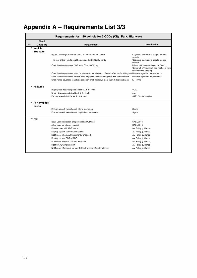
58
Appendix A – Requirements List 3/3
NrNeed
Category Justification7 Vehicle
StructureEquip 2 turn signals in front and 2 on the rear of the vehicle Cognitive feedback to people around
vehicleThe rear of the vehicle shall be equipped with 2 brake lights Cognitive feedback to people around
vehicleFront lane keep camera Horizontal FOV >=150 deg Minimum turning radius of car 30cm.
Camera FOV must not lose neither of road lines for lane keeping
Front lane keep camera must be placed such that horizon line is visible, while falling no more than 15 cm away from vehicle front axleB-snake algorithm requirementsFront lane keep camera sensor must be placed in coincident plane with car centerline B-snake algorithm requirementsShort range coverage to vehicle proximity shall not leave more than X deg blind spots ERTRAC
8 FeaturesHigh-speed freeway speed shall be 7 ± 0.4 km/h VDAUrban driving speed shall be 5 ± 0.4 km/h ownParking speed shall be <= 1 ± 0.4 km/h SAE J3016 examples
9 Performance needs
Ensure smooth execution of lateral movement SigmaEnsure smooth execution of longitudinal movement Sigma
10 HMIIssue user notification of approaching ODD exit SAE J3016Allow override at user request SAE J3016Provide user with ADS status AV Policy guidanceDisplay system performance status AV Policy guidanceNotify user when ADS is currently engaged AV Policy guidanceDisplay current DDT of ADS AV Policy guidanceNotify user when ADS is not available AV Policy guidanceNotify of ADS malfunction AV Policy guidanceNotify user of request for user-fallback in case of system failure AV Policy guidance
Requirement
Requirements for 1:10 vehicle for 3 ODDs (City, Park, Highway)
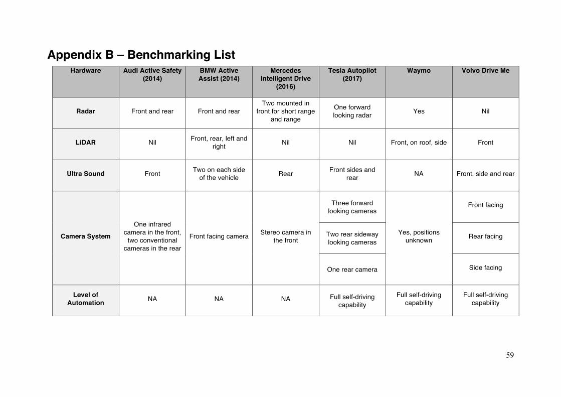
59
Appendix B – Benchmarking List Hardware Audi Active Safety
(2014)
BMW Active Assist (2014)
Mercedes Intelligent Drive
(2016)
Tesla Autopilot (2017)
Waymo
Volvo Drive Me
Radar Front and rear Front and rear Two mounted in
front for short range and range
One forward looking radar Yes Nil
LiDAR Nil Front, rear, left and right Nil Nil Front, on roof, side Front
Ultra Sound Front Two on each side of the vehicle Rear Front sides and
rear NA Front, side and rear
Camera System
One infrared camera in the front,
two conventional cameras in the rear
Front facing camera Stereo camera in the front
Three forward looking cameras
Yes, positions unknown
Front facing
Two rear sideway looking cameras
Rear facing
One rear camera Side facing
Level of Automation NA NA NA Full self-driving
capability Full self-driving
capability Full self-driving
capability
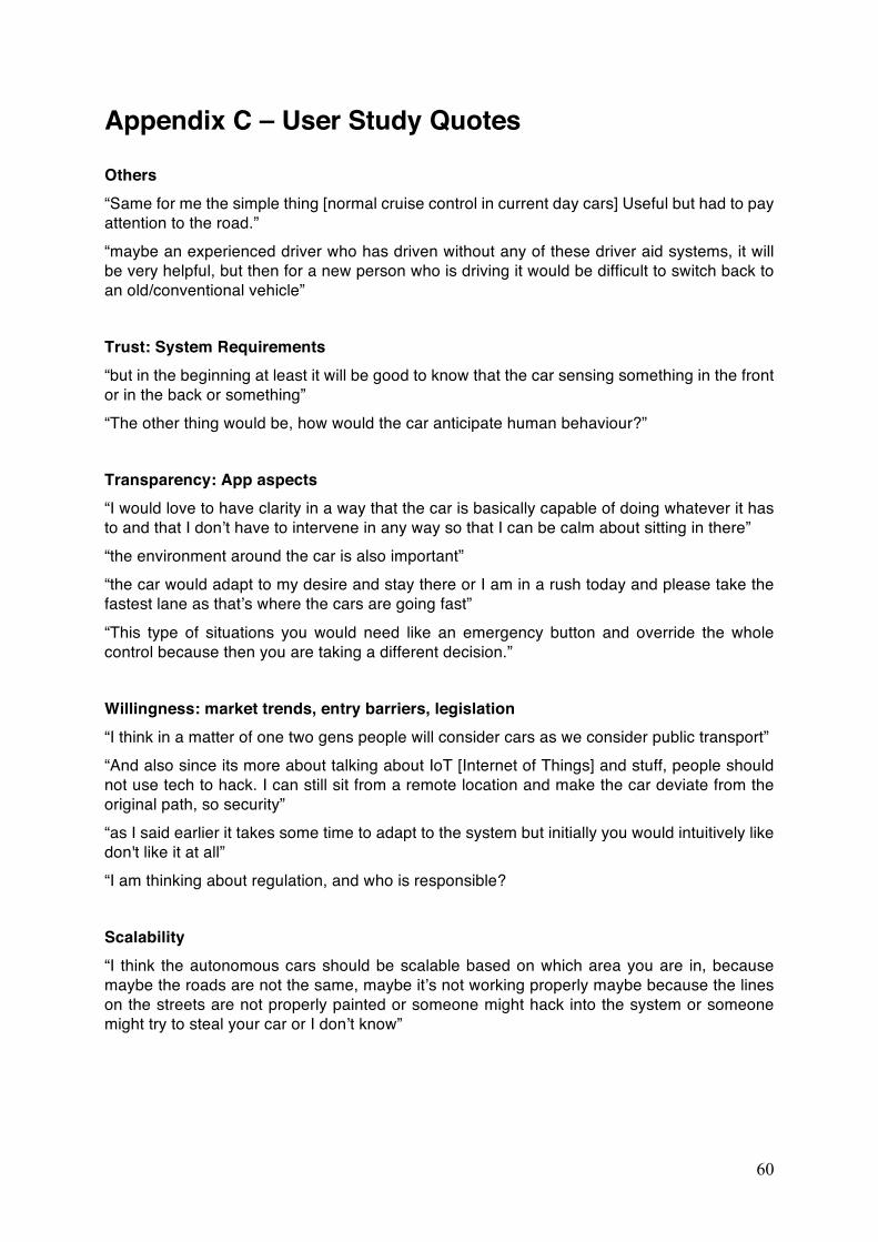
60
Appendix C – User Study Quotes Others “Same for me the simple thing [normal cruise control in current day cars] Useful but had to pay attention to the road.” “maybe an experienced driver who has driven without any of these driver aid systems, it will be very helpful, but then for a new person who is driving it would be difficult to switch back to an old/conventional vehicle” Trust: System Requirements “but in the beginning at least it will be good to know that the car sensing something in the front or in the back or something” “The other thing would be, how would the car anticipate human behaviour?” Transparency: App aspects “I would love to have clarity in a way that the car is basically capable of doing whatever it has to and that I don’t have to intervene in any way so that I can be calm about sitting in there” “the environment around the car is also important” “the car would adapt to my desire and stay there or I am in a rush today and please take the fastest lane as that’s where the cars are going fast”
“This type of situations you would need like an emergency button and override the whole control because then you are taking a different decision.” Willingness: market trends, entry barriers, legislation “I think in a matter of one two gens people will consider cars as we consider public transport” “And also since its more about talking about IoT [Internet of Things] and stuff, people should not use tech to hack. I can still sit from a remote location and make the car deviate from the original path, so security” “as I said earlier it takes some time to adapt to the system but initially you would intuitively like don't like it at all” “I am thinking about regulation, and who is responsible? Scalability “I think the autonomous cars should be scalable based on which area you are in, because maybe the roads are not the same, maybe it’s not working properly maybe because the lines on the streets are not properly painted or someone might hack into the system or someone might try to steal your car or I don’t know”
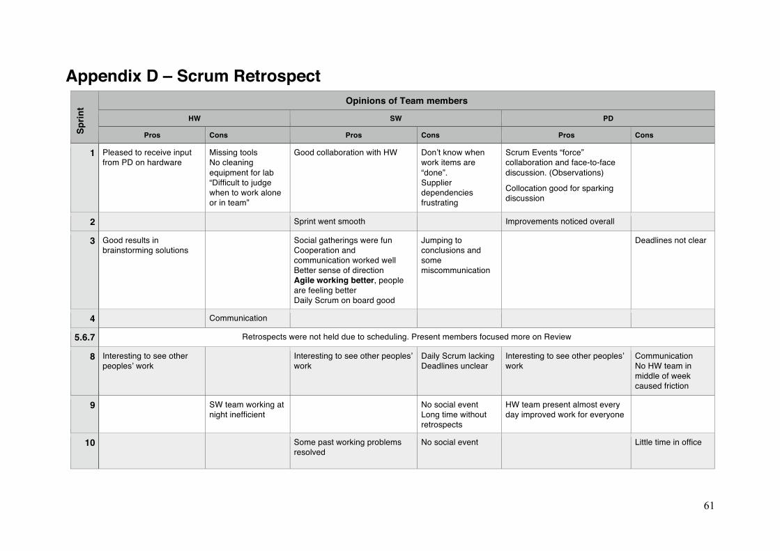
61
Appendix D – Scrum Retrospect Sp
rint
Opinions of Team members
HW SW PD
Pros Cons Pros Cons Pros Cons
1 Pleased to receive input from PD on hardware
Missing tools No cleaning equipment for lab “Difficult to judge when to work alone or in team”
Good collaboration with HW Don’t know when work items are “done”. Supplier dependencies frustrating
Scrum Events “force” collaboration and face-to-face discussion. (Observations)
Collocation good for sparking discussion
2 Sprint went smooth Improvements noticed overall
3 Good results in brainstorming solutions
Social gatherings were fun Cooperation and communication worked well Better sense of direction Agile working better, people are feeling better Daily Scrum on board good
Jumping to conclusions and some miscommunication
Deadlines not clear
4 Communication
5.6.7 Retrospects were not held due to scheduling. Present members focused more on Review
8 Interesting to see other peoples’ work
Interesting to see other peoples’ work
Daily Scrum lacking Deadlines unclear
Interesting to see other peoples’ work
Communication No HW team in middle of week caused friction
9 SW team working at night inefficient
No social event Long time without retrospects
HW team present almost every day improved work for everyone
10 Some past working problems resolved
No social event Little time in office
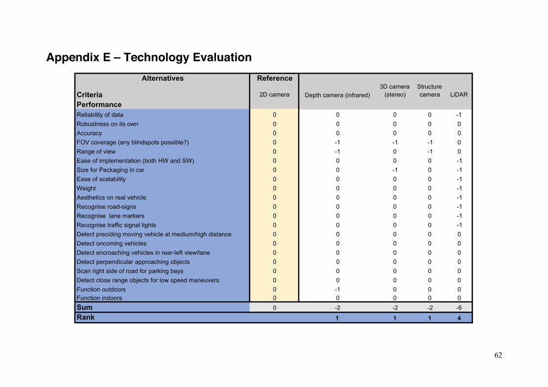
62
Appendix E – Technology Evaluation
Alternatives Reference
Criteria 2D camera Depth camera (infrared)3D camera
(stereo)Structure camera LiDAR
PerformanceReliability of data 0 0 0 0 -1Robustness on its own 0 0 0 0 0Accuracy 0 0 0 0 0FOV coverage (any blindspots possible?) 0 -1 -1 -1 0Range of view 0 -1 0 -1 0Ease of implementation (both HW and SW) 0 0 0 0 -1Size for Packaging in car 0 0 -1 0 -1Ease of scalability 0 0 0 0 -1Weight 0 0 0 0 -1Aesthetics on real vehicle 0 0 0 0 -1Recognise road-signs 0 0 0 0 -1Recognise lane markers 0 0 0 0 -1Recognise traffic signal lights 0 0 0 0 -1Detect preciding moving vehicle at medium/high distance 0 0 0 0 0Detect oncoming vehicles 0 0 0 0 0Detect encroaching vehicles in rear-left view/lane 0 0 0 0 0Detect perpendicular approaching objects 0 0 0 0 0Scan right side of road for parking bays 0 0 0 0 0Detect close range objects for low speed maneuvers 0 0 0 0 0Function outdoors 0 -1 0 0 0Function indoors 0 0 0 0 0Sum 0 -2 -2 -2 -6Rank 1 1 1 4
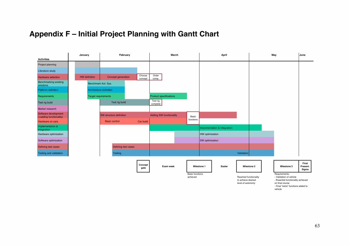
63
Appendix F – Initial Project Planning with Gantt Chart
JuneActivities
Project planning
Literature study
Hardware selection Choose concept
Order comp.
Benchmarking existing solutions Benchmark Aut. Sys.
Platform definition Architecture definition
Requirements Target requirements Product specifications
Test rig build Test rig complete
Market research
Software development (+adding functionality) SW structure definition Adding SW functionality
Hardware on cars Car build
Implementation & integration Implementation & Integration
Hardware optimization HW optimization
Software optimization SW optimization
Defining test cases Defining test cases
Testing and validation Testing Validation
Concept gate Exam week
Final Present. Sigma
Milestone 3
Requirements:- Validation of vehicle- Essential functionality achieved on final course- Final "extra" functions added to vehicle
May
HW definition Concept generation
Test rig build
January February March April
Basic functionsBasic control
Basic functions achieved Reached functionality
to achieve desired level of autonomy
EasterMilestone 1 Milestone 2