Embed Size (px)
Citation preview
Agilent 8860 Gas Chromatograph
Installation and First Startup
Installation and First Startup
Notices© Agilent Technologies, Inc. 2019
No part of this manual may be reproduced in any form or by any means (including electronic storage and retrieval or translation into a foreign language) without prior agreement and written consent from Agilent, Inc. as governed by United States and international copyright laws.
Manual Part NumberG2790-90013
EditionFirst edition, January 2019Printed in USA
Agilent Technologies, Inc.2850 Centerville Road Wilmington, DE 19808-1610 USA
安捷伦科技(上海)有限公司 上海市浦东新区外高桥保税区 英伦路412号 联系电话:(800)820 3278
WarrantyThe material contained in this document is provided “as is,” and is subject to being changed, without notice, in future editions. Further, to the maximum extent permitted by applicable law, Agilent disclaims all warranties, either express or implied, with regard to this manual and any information contained herein, including but not limited to the implied warranties of merchantability and fitness for a particular purpose. Agilent shall not be liable for errors or for incidental or consequential damages in connection with the furnishing, use, or performance of this document or of any information contained herein. Should Agilent and the user have a separate written agreement with warranty terms covering the material in this document that conflict with these terms, the warranty terms in the separate agreement shall control.
Technology Licenses The hardware and/or software described in this document are furnished under a license and may be used or copied only in accordance with the terms of such license.
Restricted Rights LegendU.S. Government Restricted Rights. Software and technical data rights granted to the federal government include only those rights customarily provided to end user customers. Agilent provides this customary commercial license in Software and technical data pursuant to FAR 12.211 (Technical Data) and 12.212 (Computer Software) and, for the Department of Defense, DFARS 252.227-7015 (Technical Data -Commercial Items) and DFARS 227.7202-3 (Rights in Commercial Computer Software or Computer Software Documentation).
Safety Notices
CAUTION
A CAUTION notice denotes a hazard. It calls attention to an operating procedure, practice, or the like that, if not correctly performed or adhered to, could result in damage to the product or loss of important data. Do not proceed beyond a CAUTION notice until the indicated conditions are fully understood and met.
WARNING
A WARNING notice denotes a hazard. It calls attention to an operating procedure, practice, or the like that, if not correctly performed or adhered to, could result in personal injury or death. Do not proceed beyond a WARNING notice until the indicated conditions are fully understood and met.
Installation and First Startup 3
Contents
1 Installing the GC
Overview of Installation 8Purpose of this procedure 8Customer responsibilities 8About Agilent’s installation service 8Tools and additional parts required 8Performing checkout 9System installation 9Configuring the GC 9
Connecting to the Browser Interface 10
The 8860 GC 11
Unpacking 12
Place the GC on the bench 13
Verify line voltage, voltage settings, and power cord 15Line voltage 15Power consumption 16Power cords available 17Grounding 21
Connect GC to LAN, Local Computer, or Tablet 22
Connect the power cord and turn on the GC 24
Configure the GC IP address 25
Set the Pressure Units 26
Configure Carrier Gas Types 27
Connect Gases and Traps 28Install the gas regulators 28Connect the tubing to the gas source 30Install traps 31Plumb to EPC flow modules 31Install Aux EPC module frits for your application 32Install hydrogen sensor calibration gas 34
Leak test all connections and set source pressures 36Set source gas pressures 38
Install inlet checkout parts 39
Install ALS, if ordered 40

4 Installation and First Startup
Configuring GC-MSD communications 41
Connect the external cables 42Back panel connectors 42Connecting cables 43GC / MS / Agilent data system / ALS 45Additional cabling configurations 45
Vent ECD or uncombusted hydrogen to a fume hood 46
Connect valve actuator air (if present) 47
Configure the checkout column 48Checkout column 48
Install the checkout column 49
Transfer the checkout sample to a screw-top sample vial 50
When the system stabilizes, run one injection 51
Prepare for the Next Analysis 52
A Making Swagelok Connections
Making Swagelok Connections 54
Using a Swagelok Tee 57
B Cabling Diagrams and Remote Start/Stop
Using the Remote Start/Stop Cable 60Connecting Agilent products 60Connecting non-Agilent products 60
Multi-instrument Cabling Examples 63GC / ALS / Non-Agilent Data System 63GC / 3395A/3396B Integrator / ALS 64GC / 3396C Integrator / ALS 64Example: Using a Y-Cable in a setup (GC/MSD/Data System/Headspace
Sampler) 65GC / External Events (unspecified, non-Agilent instrument) 66
Cable Diagrams 67Analog signal cable, general use, G1530-60560 67Agilent analog signal cable, G1530-60570 68Remote start/stop cable, general use, 35900-60670 68Agilent APG remote start/stop cable, 03396-61010 69Agilent APG remote start/stop cable, G1530-60930 69Agilent remote start/stop Y-cable, G1530-61200 70External event cable, G1530-60590 72

Installation and First Startup 5
External valve cable, G1580-60710 73Pulser module power supply cable, G1580-60730 73

6 Installation and First Startup
Installation and First Startup 7
1 Installing the GCOverview of Installation 8
Connecting to the Browser Interface 10
The 8860 GC 11
Unpacking 12
Place the GC on the bench 13
Verify line voltage, voltage settings, and power cord 15
Connect GC to LAN, Local Computer, or Tablet 22
Connect the power cord and turn on the GC 24
Configure the GC IP address 25
Set the Pressure Units 26
Configure Carrier Gas Types 27
Connect Gases and Traps 28
Leak test all connections and set source pressures 36
Install ALS, if ordered 40
Connect the external cables 42
Vent ECD or uncombusted hydrogen to a fume hood 46
Configure the checkout column 48
Install the checkout column 49
Transfer the checkout sample to a screw-top sample vial 50
When the system stabilizes, run one injection 51
Prepare for the Next Analysis 52
This section contains installation procedures for the Agilent 8860 GC. Depending on the ordered options, some steps are optional, such as connecting valve actuator air.
Instructions for connecting cables from the GC to other instruments in a typical 8860 Series system are included here and in Appendix B, “Cabling Diagrams and Remote Start/Stop” on page 59“.
1 Installing the GC
8 Installation and First Startup
Overview of Installation
Purpose of this procedureThis procedure ensures that instruments and systems are installed and functioning as designed. Correct installation is the first step in ensuring that instruments and systems operate reliably over their lifetimes.
Customer responsibilities1 Make sure your site meets the basic requirements, including the necessary space,
electrical outlets, gases, tubing, operating supplies, consumables and other usage-dependent items, required for a successful installation. Refer to the Agilent 8860 Gas Chromatograph GC, GC/MS, and ALS Site Preparation Guide.
2 If Agilent is delivering installation and familiarization services, users of the instrument should be present throughout these services; otherwise, these users will miss important operational, maintenance, and safety information.
Additional information is available via the Browser Interface help & information suite and the Agilent GC and GC/MS User Manuals & Tools DVD.
About Agilent’s installation serviceThe installation service does not include:
• Network setup with other computers, or to the site or building LAN.
• Customization of the system.
• Method development and testing.
• Analysis of customer standards or samples.
• Testing against the instrument performance specification.
If you need assistance beyond this installation service, please contact your local Agilent office. Assistance with installation and with user-specific services and applications is available and will be contracted separately.
Tools and additional parts requiredInstallation requires the following tools, fittings, and hardware. These items are not included with the instrument.
• Precleaned copper tubing, 1/8-inch or 1/4-inch od.
• Fittings.
• Tubing cutter.
• Filters for gas supplies.
• 7/16-inch and 9/16-inch wrenches for assembling Swagelok fittings.
• Carrier and other gas supplies.
1 Installing the GC
Installation and First Startup 9
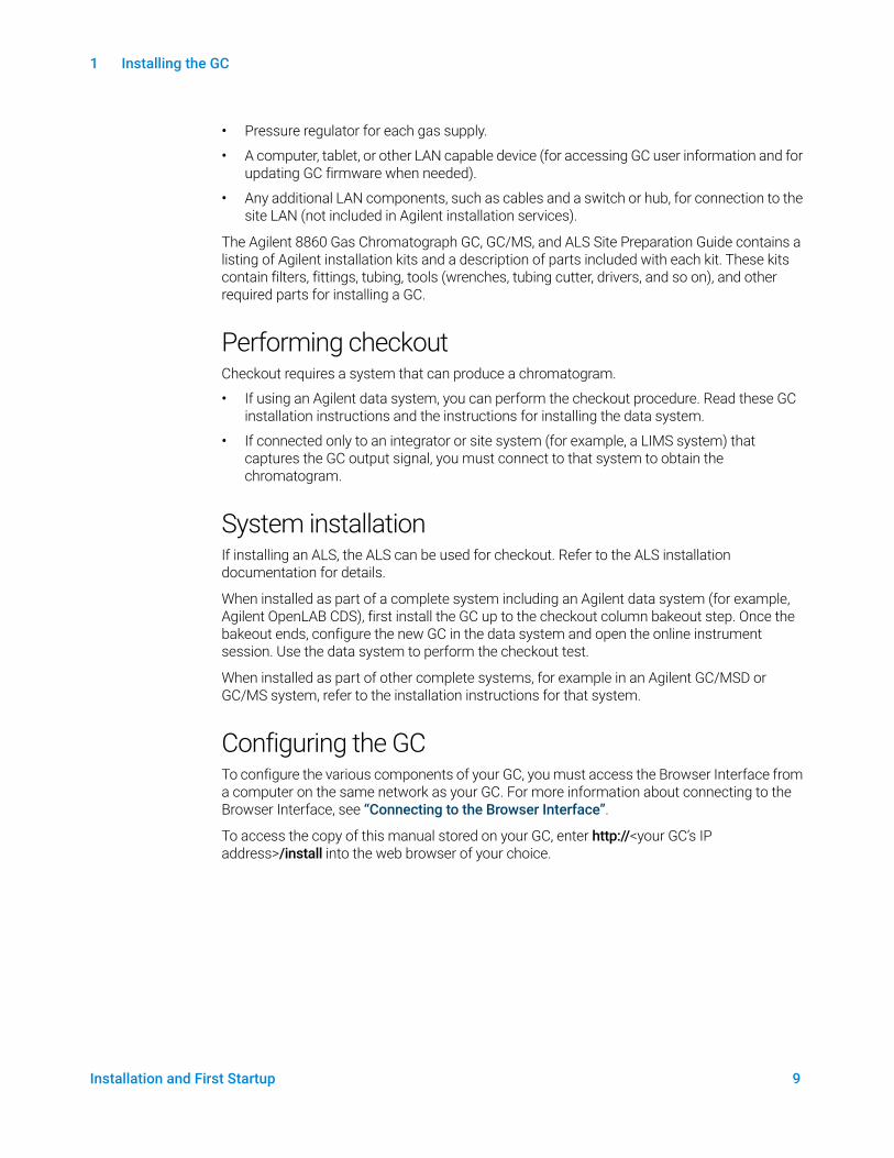
• Pressure regulator for each gas supply.
• A computer, tablet, or other LAN capable device (for accessing GC user information and for updating GC firmware when needed).
• Any additional LAN components, such as cables and a switch or hub, for connection to the site LAN (not included in Agilent installation services).
The Agilent 8860 Gas Chromatograph GC, GC/MS, and ALS Site Preparation Guide contains a listing of Agilent installation kits and a description of parts included with each kit. These kits contain filters, fittings, tubing, tools (wrenches, tubing cutter, drivers, and so on), and other required parts for installing a GC.
Performing checkoutCheckout requires a system that can produce a chromatogram.
• If using an Agilent data system, you can perform the checkout procedure. Read these GC installation instructions and the instructions for installing the data system.
• If connected only to an integrator or site system (for example, a LIMS system) that captures the GC output signal, you must connect to that system to obtain the chromatogram.
System installationIf installing an ALS, the ALS can be used for checkout. Refer to the ALS installation documentation for details.
When installed as part of a complete system including an Agilent data system (for example, Agilent OpenLAB CDS), first install the GC up to the checkout column bakeout step. Once the bakeout ends, configure the new GC in the data system and open the online instrument session. Use the data system to perform the checkout test.
When installed as part of other complete systems, for example in an Agilent GC/MSD or GC/MS system, refer to the installation instructions for that system.
Configuring the GCTo configure the various components of your GC, you must access the Browser Interface from a computer on the same network as your GC. For more information about connecting to the Browser Interface, see “Connecting to the Browser Interface”.
To access the copy of this manual stored on your GC, enter http://<your GC’s IP address>/install into the web browser of your choice.
1 Installing the GC
10 Installation and First Startup
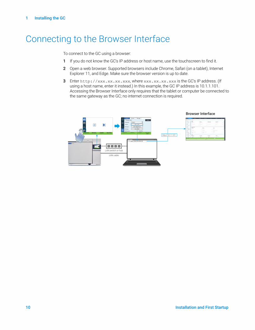
Connecting to the Browser InterfaceTo connect to the GC using a browser:
1 If you do not know the GC's IP address or host name, use the touchscreen to find it.
2 Open a web browser. Supported browsers include Chrome, Safari (on a tablet), Internet Explorer 11, and Edge. Make sure the browser version is up to date.
3 Enter http://xxx.xx.xx.xxx, where xxx.xx.xx.xxx is the GC's IP address. (If using a host name, enter it instead.) In this example, the GC IP address is 10.1.1.101. Accessing the Browser Interface only requires that the tablet or computer be connected to the same gateway as the GC; no internet connection is required.
LAN switch or hub
Browser Interface
LAN cable
X8860 GC
http://XXX.XX.XXX.XX
http://10.1.1.101
1 Installing the GC
Installation and First Startup 11
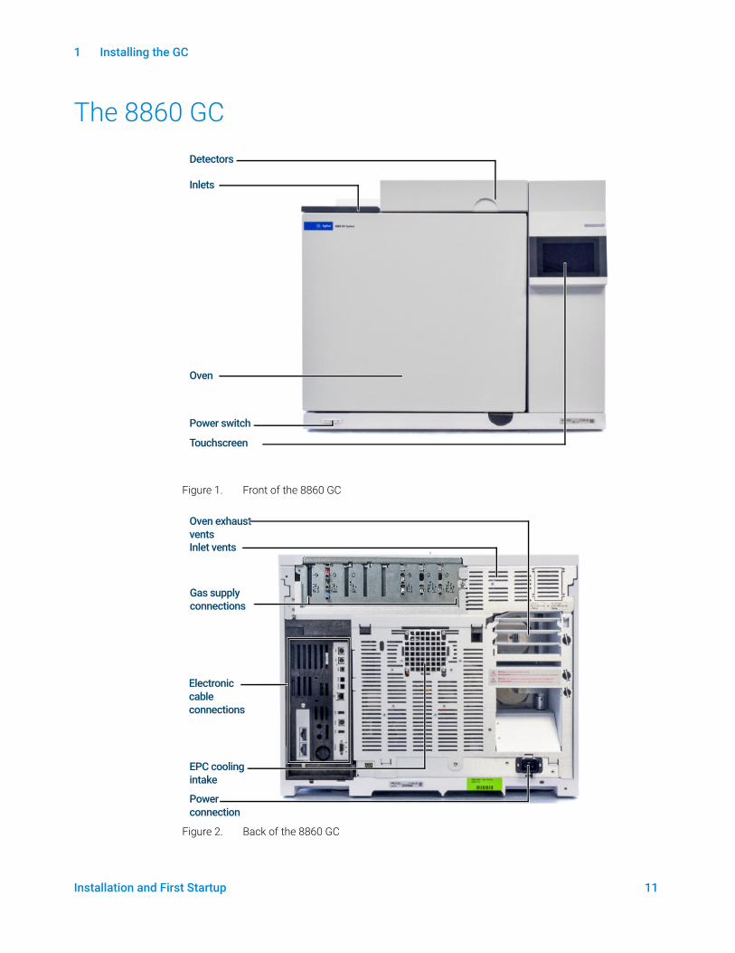
The 8860 GC
Figure 1. Front of the 8860 GC
Figure 2. Back of the 8860 GC
Inlets
Oven
Detectors
Power switch
Touchscreen
Inlet vents
Electronic cable connections
Oven exhaust vents
EPC cooling intake
Power connection
Gas supply connections
1 Installing the GC
12 Installation and First Startup
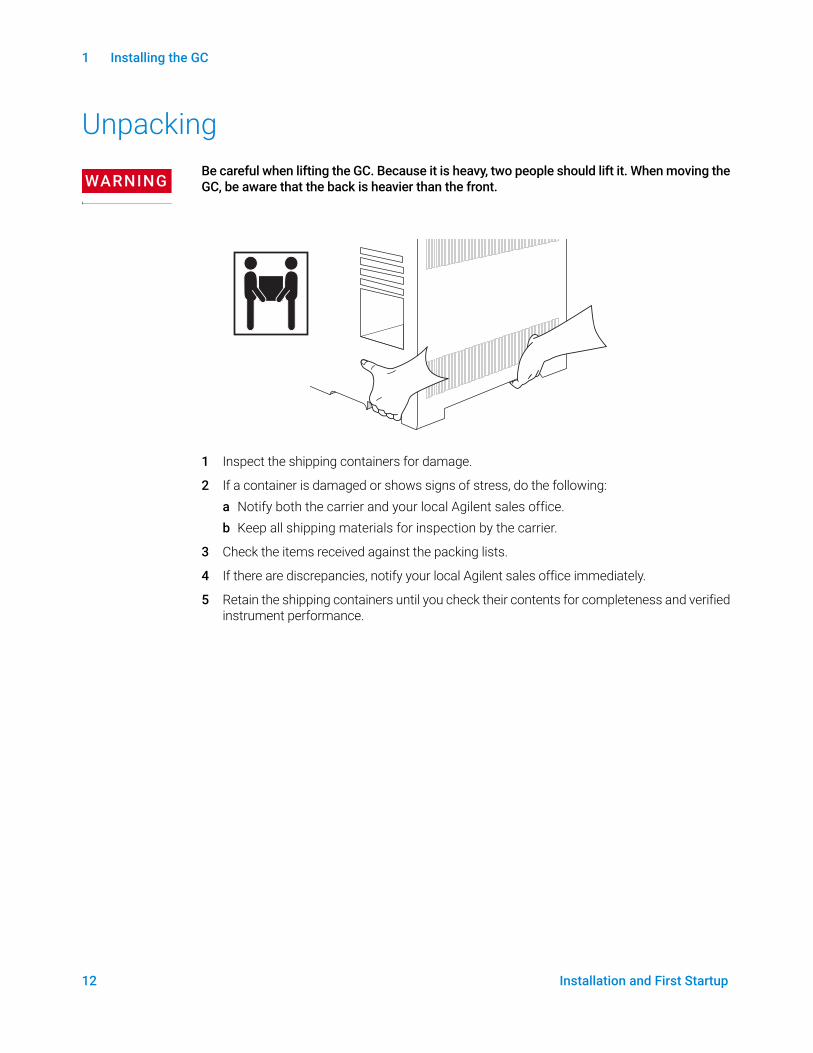
Unpacking
WARNINGBe careful when lifting the GC. Because it is heavy, two people should lift it. When moving the GC, be aware that the back is heavier than the front.
1 Inspect the shipping containers for damage.
2 If a container is damaged or shows signs of stress, do the following:a Notify both the carrier and your local Agilent sales office.b Keep all shipping materials for inspection by the carrier.
3 Check the items received against the packing lists.
4 If there are discrepancies, notify your local Agilent sales office immediately.
5 Retain the shipping containers until you check their contents for completeness and verified instrument performance.
1 Installing the GC
Installation and First Startup 13
Step 1 Place the GC on the bench
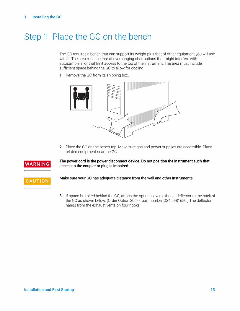
The GC requires a bench that can support its weight plus that of other equipment you will use with it. The area must be free of overhanging obstructions that might interfere with autosamplers, or that limit access to the top of the instrument. The area must include sufficient space behind the GC to allow for cooling.
1 Remove the GC from its shipping box.
2 Place the GC on the bench top. Make sure gas and power supplies are accessible. Place related equipment near the GC.
WARNINGThe power cord is the power disconnect device. Do not position the instrument such that access to the coupler or plug is impaired.
CAUTIONMake sure your GC has adequate distance from the wall and other instruments.
3 If space is limited behind the GC, attach the optional oven exhaust deflector to the back of the GC as shown below. (Order Option 306 or part number G3450-81650.) The deflector hangs from the exhaust vents on four hooks.
1 Installing the GC
14 Installation and First Startup
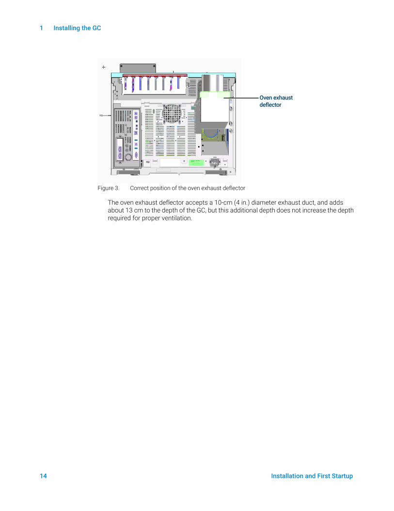
Figure 3. Correct position of the oven exhaust deflector
The oven exhaust deflector accepts a 10-cm (4 in.) diameter exhaust duct, and adds about 13 cm to the depth of the GC, but this additional depth does not increase the depth required for proper ventilation.
Oven exhaust deflector
1 Installing the GC
Installation and First Startup 15
Step 2 Verify line voltage, voltage settings, and power cord
1 Locate the power label near the power cord connector on the back of the GC. Compare the instrument power settings with the laboratory line voltage. See “Power consumption” on page 16.
2 Verify that the power cord is correct for the voltage and location. “Power cords available” on page 17.
WARNINGElectrical shock hazard. To avoid injury, only a qualified person should measure line voltage.
3 Have a qualified person measure the actual power outlet voltage and verify that it meets the tolerance requirements listed in Table 1 on page 16. See “Grounding” on page 21“ and “Line voltage” on page 15.
The following sections detail the power specifications and requirements for reference.
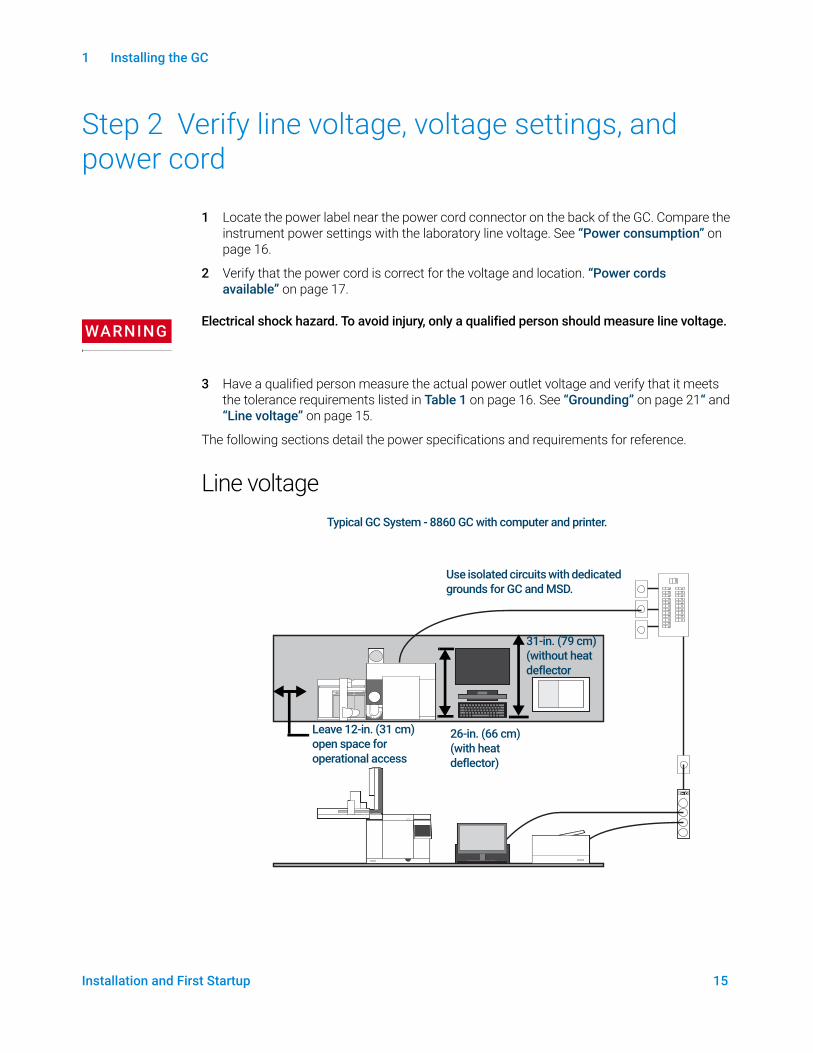
Line voltageTypical GC System - 8860 GC with computer and printer.
Use isolated circuits with dedicated grounds for GC and MSD.
Leave 12-in. (31 cm) open space for operational access
31-in. (79 cm) (without heat deflector
26-in. (66 cm) (with heat deflector)
1 Installing the GC
16 Installation and First Startup
WARNINGTo protect users, the metal instrument panels and cabinet are grounded through the three-conductor power line cord in accordance with International Electrotechnical Commission (IEC) requirements.
A proper earth ground is required for GC operations. Any interruption of the grounding conductor or disconnection of the power cord could cause a shock that could result in personal injury.
Be sure to verify proper receptacle grounding.
WARNINGDo not use extension cords with Agilent instruments. Extension cords normally are not rated to carry enough power and can be a safety hazard.
1 Make sure that each instrument in your GC system can be connected to a dedicated circuit with an isolated ground. (Note that ALS instruments receive their power from the GC.)
2 Power requirements are printed near the power cord attachment on the rear panel of each instrument. Although your GC should arrive ready for operation in your country, compare its voltage requirements with those listed in Table 1 on page 16. If the voltage option you ordered is not suitable for your installation, contact Agilent.
Power consumptionThe number and type of electrical outlets required for installation depends on the size and complexity of your system. A GC system with a computer, monitor, printer, and hub requires 5 outlets. The outlet for the GC must be a dedicated circuit.
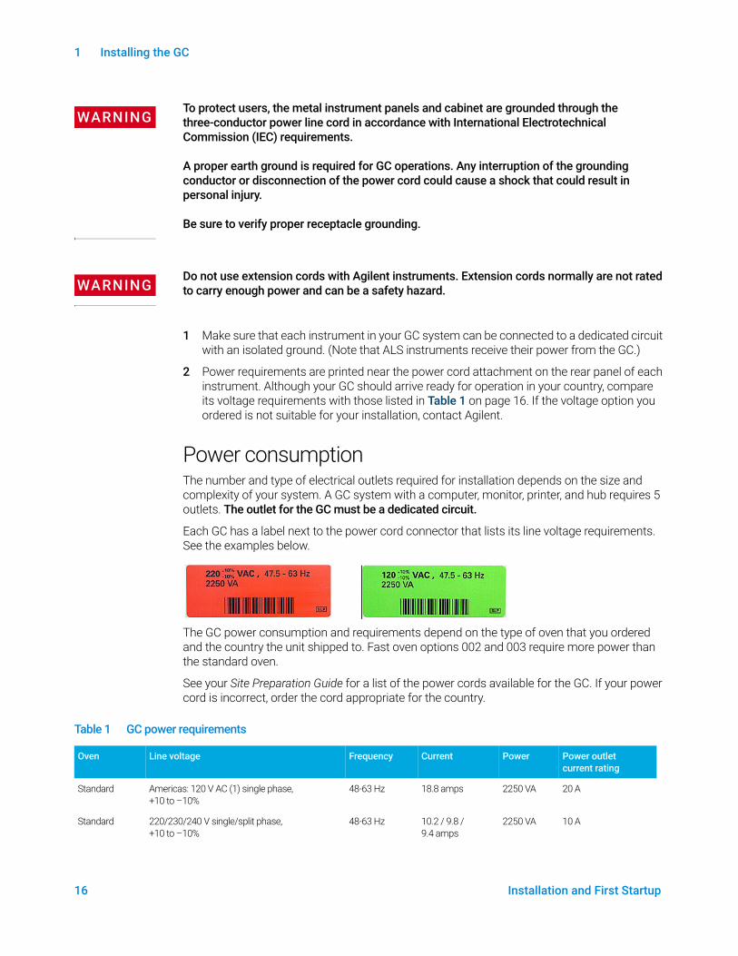
Each GC has a label next to the power cord connector that lists its line voltage requirements. See the examples below.
The GC power consumption and requirements depend on the type of oven that you ordered and the country the unit shipped to. Fast oven options 002 and 003 require more power than the standard oven.
See your Site Preparation Guide for a list of the power cords available for the GC. If your power cord is incorrect, order the cord appropriate for the country.
Table 1 GC power requirements
Oven Line voltage Frequency Current Power Power outlet current rating
Standard Americas: 120 V AC (1) single phase,+10 to –10%
48-63 Hz 18.8 amps 2250 VA 20 A
Standard 220/230/240 V single/split phase, +10 to –10%
48-63 Hz 10.2 / 9.8 / 9.4 amps
2250 VA 10 A
1 Installing the GC
Installation and First Startup 17
Notes
1 Some US labs have 3 phase service resulting in 208 V at the wall receptacle. It is important for a qualified person to measure the line voltage at the receptacle for the GC. Option 003, 208 V fast oven, uses a 220 V unit with operating range of 193 to 231 V.
2 Power line conditioners should not be used with the GC.
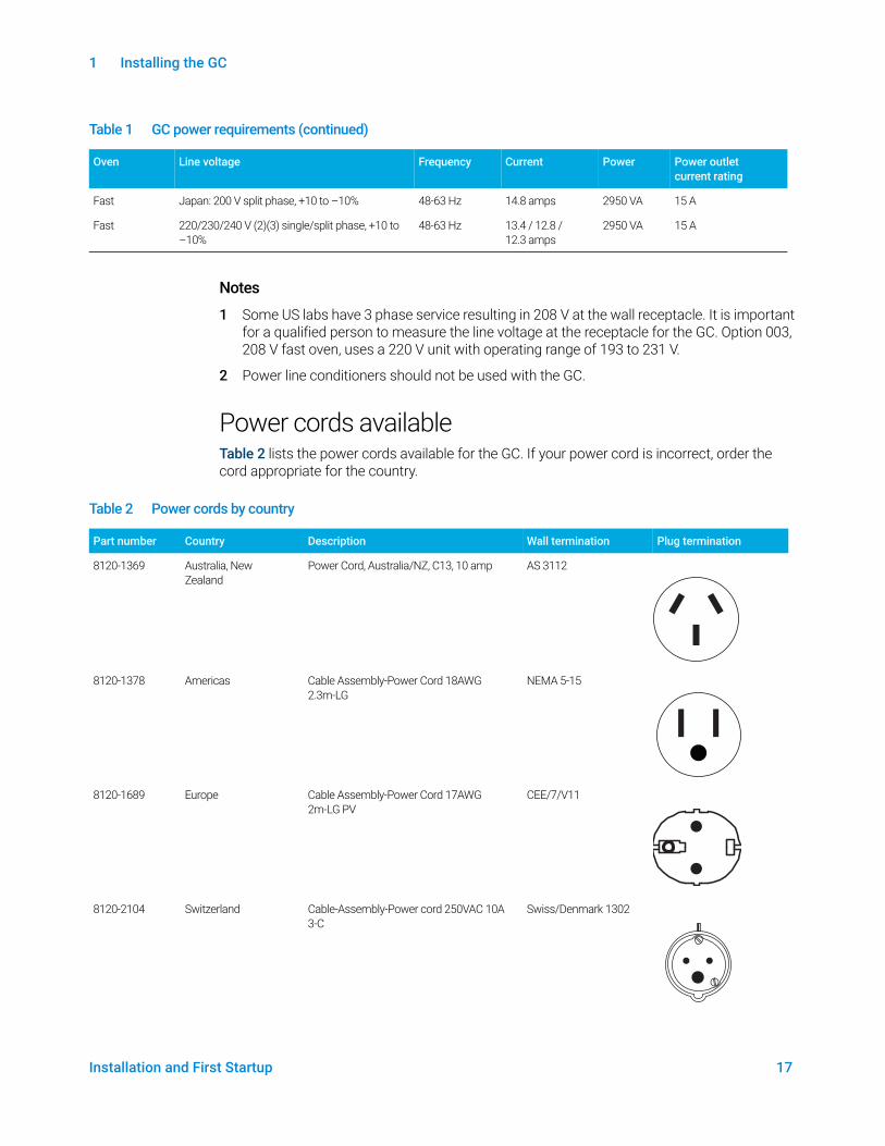
Power cords availableTable 2 lists the power cords available for the GC. If your power cord is incorrect, order the cord appropriate for the country.
Fast Japan: 200 V split phase, +10 to –10% 48-63 Hz 14.8 amps 2950 VA 15 A
Fast 220/230/240 V (2)(3) single/split phase, +10 to –10%
48-63 Hz 13.4 / 12.8 / 12.3 amps
2950 VA 15 A
Table 1 GC power requirements (continued)
Oven Line voltage Frequency Current Power Power outlet current rating
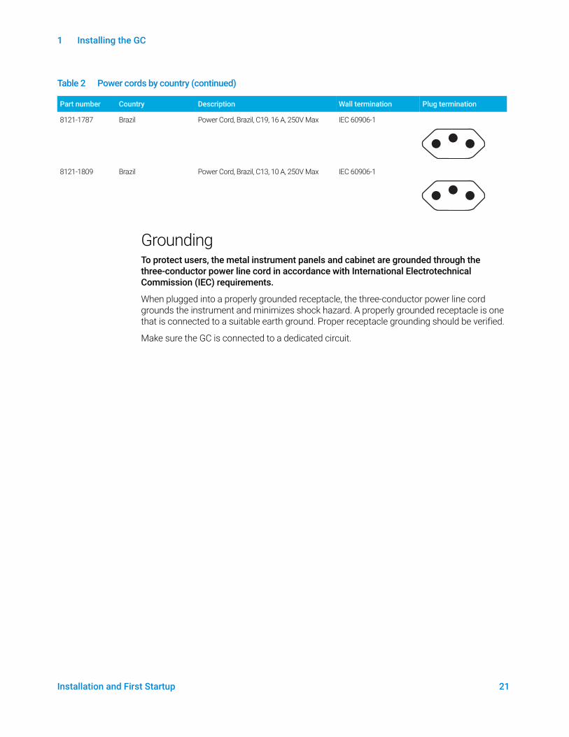
Table 2 Power cords by country
Part number Country Description Wall termination Plug termination
8120-1369 Australia, New Zealand
Power Cord, Australia/NZ, C13, 10 amp AS 3112
8120-1378 Americas Cable Assembly-Power Cord 18AWG 2.3m-LG
NEMA 5-15
8120-1689 Europe Cable Assembly-Power Cord 17AWG 2m-LG PV
CEE/7/V11
8120-2104 Switzerland Cable-Assembly-Power cord 250VAC 10A 3-C
Swiss/Denmark 1302
1 Installing the GC
18 Installation and First Startup
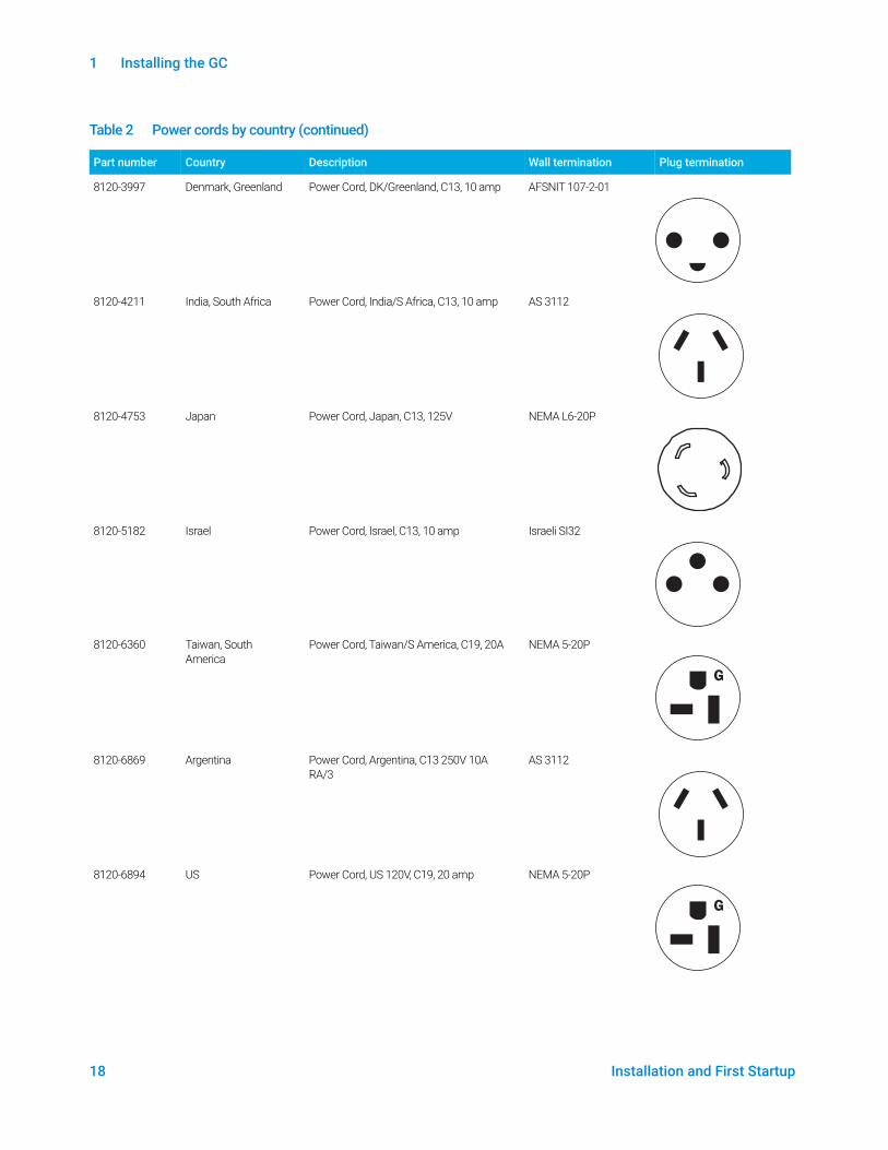
8120-3997 Denmark, Greenland Power Cord, DK/Greenland, C13, 10 amp AFSNIT 107-2-01
8120-4211 India, South Africa Power Cord, India/S Africa, C13, 10 amp AS 3112
8120-4753 Japan Power Cord, Japan, C13, 125V NEMA L6-20P
8120-5182 Israel Power Cord, Israel, C13, 10 amp Israeli SI32
8120-6360 Taiwan, South America
Power Cord, Taiwan/S America, C19, 20A NEMA 5-20P
8120-6869 Argentina Power Cord, Argentina, C13 250V 10A RA/3
AS 3112
8120-6894 US Power Cord, US 120V, C19, 20 amp NEMA 5-20P
Table 2 Power cords by country (continued)
Part number Country Description Wall termination Plug termination
G
G
1 Installing the GC
Installation and First Startup 19
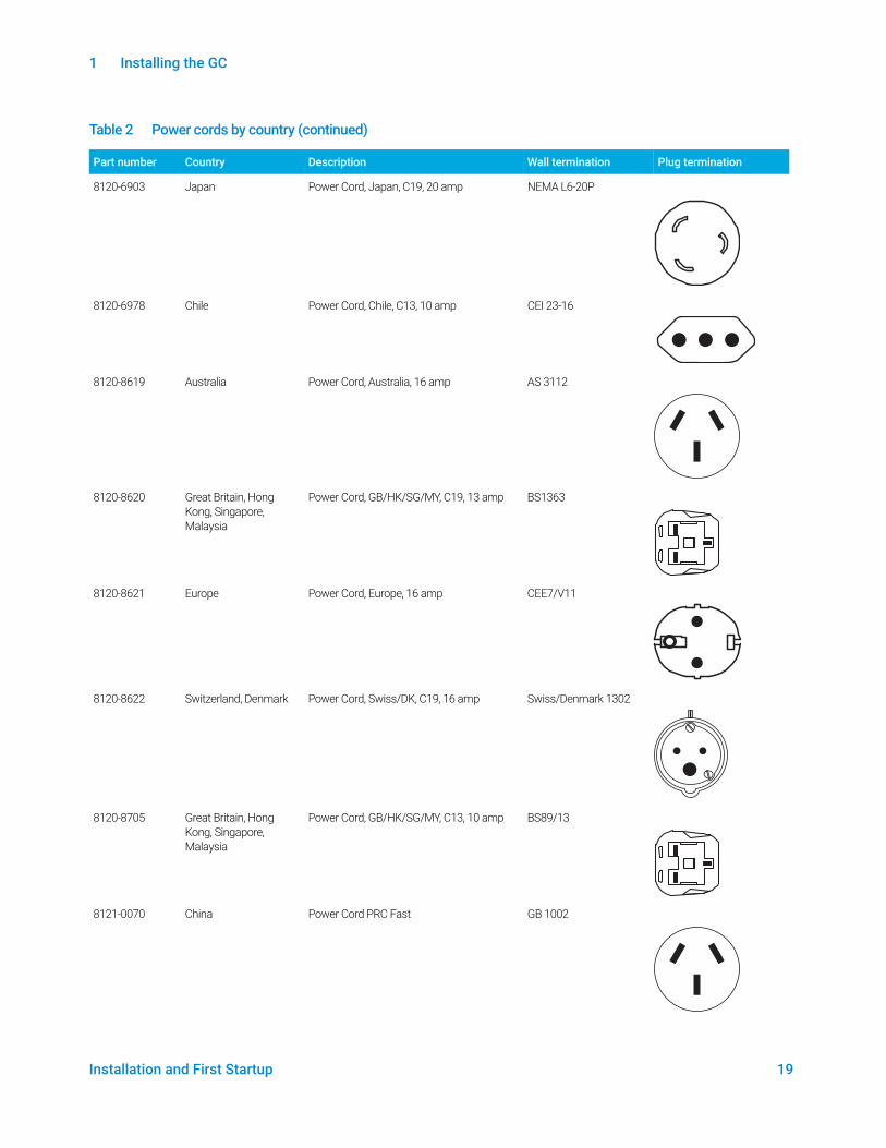
8120-6903 Japan Power Cord, Japan, C19, 20 amp NEMA L6-20P
8120-6978 Chile Power Cord, Chile, C13, 10 amp CEI 23-16
8120-8619 Australia Power Cord, Australia, 16 amp AS 3112
8120-8620 Great Britain, Hong Kong, Singapore, Malaysia
Power Cord, GB/HK/SG/MY, C19, 13 amp BS1363
8120-8621 Europe Power Cord, Europe, 16 amp CEE7/V11
8120-8622 Switzerland, Denmark Power Cord, Swiss/DK, C19, 16 amp Swiss/Denmark 1302
8120-8705 Great Britain, Hong Kong, Singapore, Malaysia
Power Cord, GB/HK/SG/MY, C13, 10 amp BS89/13
8121-0070 China Power Cord PRC Fast GB 1002
Table 2 Power cords by country (continued)
Part number Country Description Wall termination Plug termination
1 Installing the GC
20 Installation and First Startup
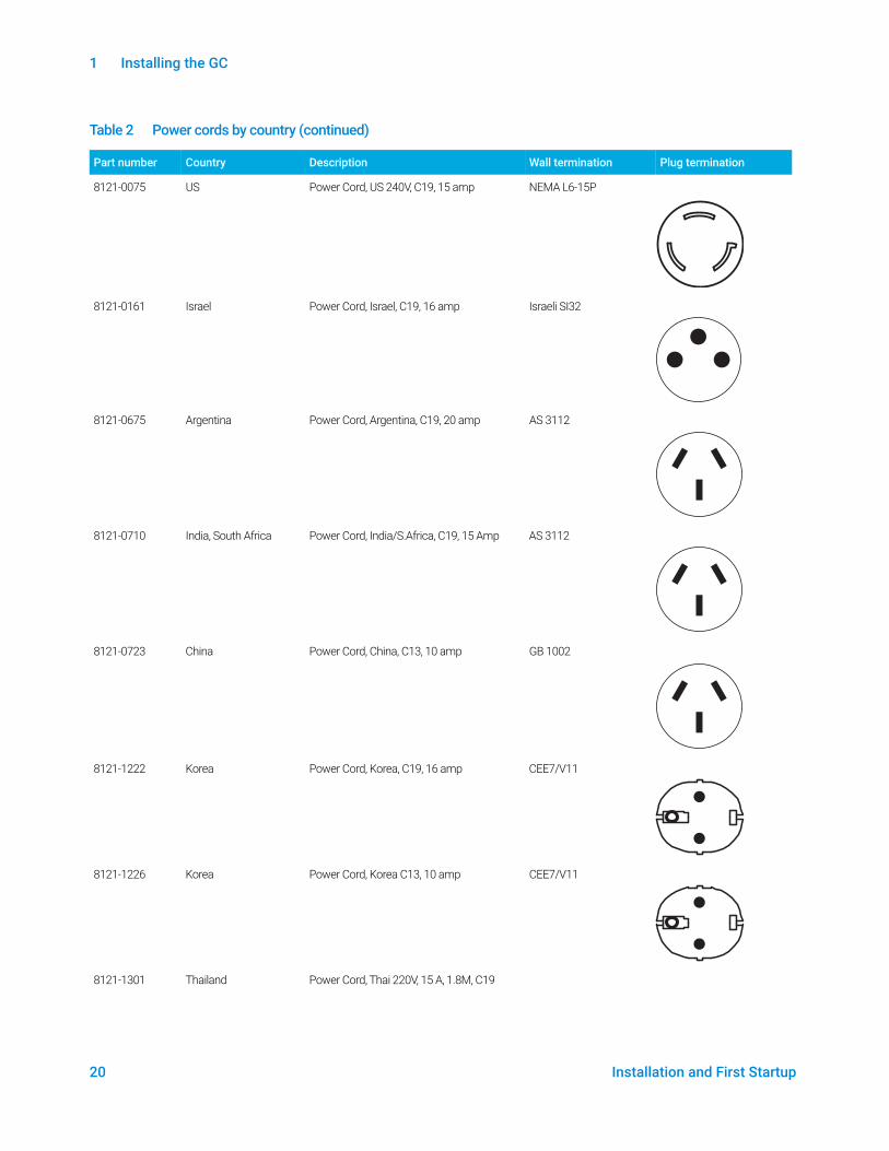
8121-0075 US Power Cord, US 240V, C19, 15 amp NEMA L6-15P
8121-0161 Israel Power Cord, Israel, C19, 16 amp Israeli SI32
8121-0675 Argentina Power Cord, Argentina, C19, 20 amp AS 3112
8121-0710 India, South Africa Power Cord, India/S.Africa, C19, 15 Amp AS 3112
8121-0723 China Power Cord, China, C13, 10 amp GB 1002
8121-1222 Korea Power Cord, Korea, C19, 16 amp CEE7/V11
8121-1226 Korea Power Cord, Korea C13, 10 amp CEE7/V11
8121-1301 Thailand Power Cord, Thai 220V, 15 A, 1.8M, C19
Table 2 Power cords by country (continued)
Part number Country Description Wall termination Plug termination
1 Installing the GC
Installation and First Startup 21
GroundingTo protect users, the metal instrument panels and cabinet are grounded through the three-conductor power line cord in accordance with International Electrotechnical Commission (IEC) requirements.
When plugged into a properly grounded receptacle, the three-conductor power line cord grounds the instrument and minimizes shock hazard. A properly grounded receptacle is one that is connected to a suitable earth ground. Proper receptacle grounding should be verified.
Make sure the GC is connected to a dedicated circuit.
8121-1787 Brazil Power Cord, Brazil, C19, 16 A, 250V Max IEC 60906-1
8121-1809 Brazil Power Cord, Brazil, C13, 10 A, 250V Max IEC 60906-1
Table 2 Power cords by country (continued)
Part number Country Description Wall termination Plug termination
1 Installing the GC
22 Installation and First Startup
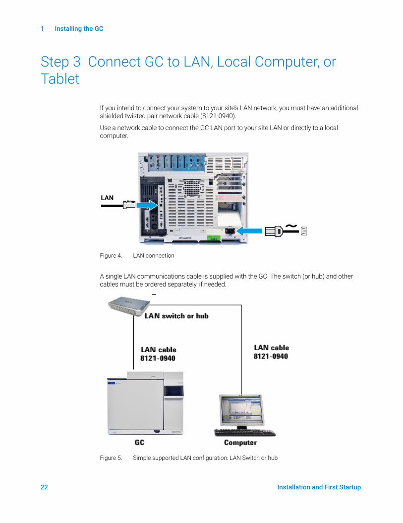
Step 3 Connect GC to LAN, Local Computer, or Tablet
If you intend to connect your system to your site’s LAN network, you must have an additional shielded twisted pair network cable (8121-0940).
Use a network cable to connect the GC LAN port to your site LAN or directly to a local computer.
A single LAN communications cable is supplied with the GC. The switch (or hub) and other cables must be ordered separately, if needed.
Figure 5. Simple supported LAN configuration: LAN Switch or hub
Figure 4. LAN connection

1 Installing the GC
Installation and First Startup 23
NOTEAgilent is not responsible for connecting to or establishing communication with your site LAN network. The Agilent representative will test the system’s ability to communicate on a mini-hub or LAN switch only.
1 Installing the GC
24 Installation and First Startup
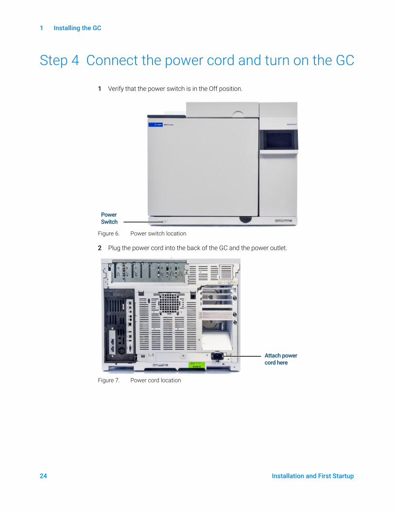
Step 4 Connect the power cord and turn on the GC
1 Verify that the power switch is in the Off position.
Figure 6. Power switch location
2 Plug the power cord into the back of the GC and the power outlet.
Figure 7. Power cord location
Power Switch
Attach power cord here

1 Installing the GC
Installation and First Startup 25
Step 5 Configure the GC IP address
If you intend to connect your system to your site’s network, each piece of equipment must have a unique IP address assigned to it. For an isolated LAN installation, see Table 3 for typical IP addresses.
1 Select the IP Config page.
2 Enter the GC IP address, Gateway, and Netmask (subnet mask).
Table 3 Typical IP addresses for an isolated LAN
GC Computer
IP address 10.1.1.101 10.1.1.100
Subnet mask 255.255.255.0 255.255.255.0

1 Installing the GC
26 Installation and First Startup
Step 6 Set the Pressure Units
To set the pressure units used in a given method, select Method > Configuration > Miscellaneous, and select the desired pressure units to use in methods.

1 Installing the GC
Installation and First Startup 27
Step 7 Configure Carrier Gas Types
Select Method > Configuration > Modules and use the dropdown menu to select the Carrier Gas Types connected to your inlets. Repeat for any additional inlets installed in your GC.
1 Installing the GC
28 Installation and First Startup
Step 8 Connect Gases and Traps
Most of installation involves plumbing gas to tanks, filters, and flow modules. Swagelok fittings are used to make leak-tight connections. If you are not sure how to make a Swagelok connection, see Appendix A, “Making Swagelok Connections” for instructions.
WARNINGHydrogen is a flammable gas. If hydrogen or any other flammable gas is used, periodic leak tests should be performed. Be sure that the hydrogen supply is off until all connections are made, and insure that the inlet fittings are either connected to a column or capped at all times when hydrogen gas is present in the instrument.
Substituting parts or performing any unauthorized modification to the instrument may result in a safety hazard.
The insulation around the inlets, detectors, valve box, and the insulation cups is made of refractory ceramic fibers (RCF). To avoid inhaling RCF particles, we recommend these safety procedures: ventilate your work area; wear long sleeves, gloves, safety glasses, and a disposable dust/mist respirator; dispose of insulation in a sealed plastic bag; wash your hands with mild soap and cold water after handling RCFs.
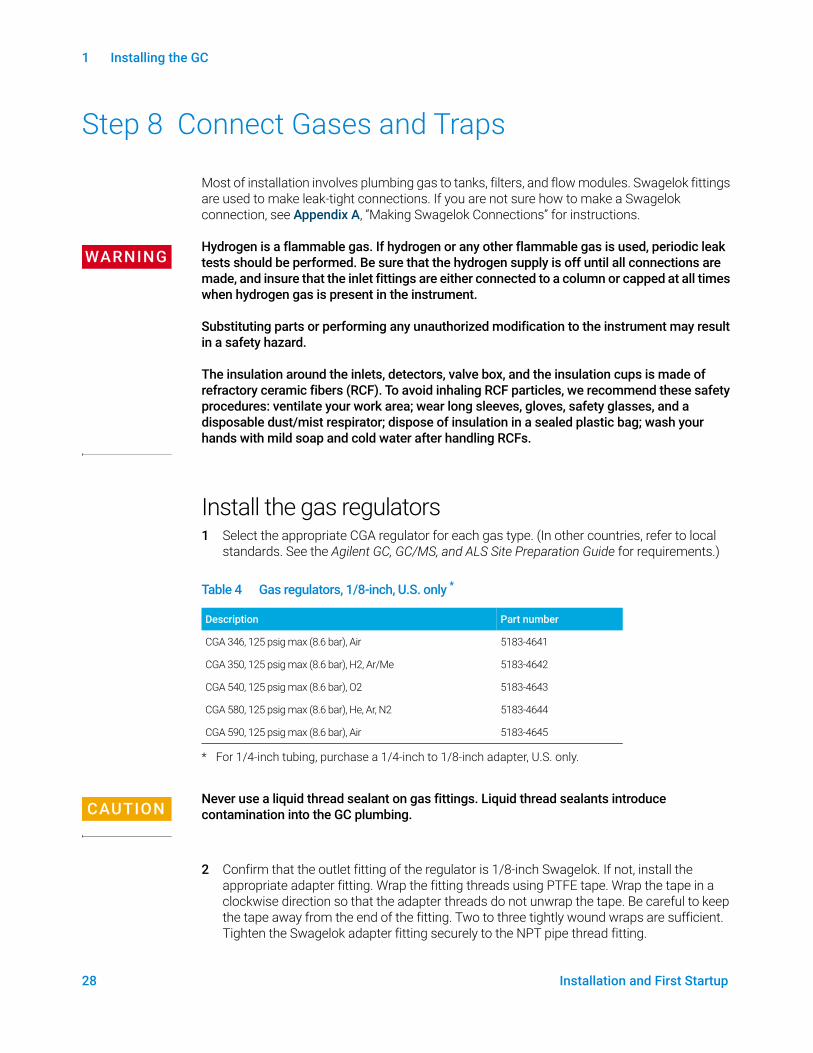
Install the gas regulators1 Select the appropriate CGA regulator for each gas type. (In other countries, refer to local
standards. See the Agilent GC, GC/MS, and ALS Site Preparation Guide for requirements.)
CAUTIONNever use a liquid thread sealant on gas fittings. Liquid thread sealants introduce contamination into the GC plumbing.
2 Confirm that the outlet fitting of the regulator is 1/8-inch Swagelok. If not, install the appropriate adapter fitting. Wrap the fitting threads using PTFE tape. Wrap the tape in a clockwise direction so that the adapter threads do not unwrap the tape. Be careful to keep the tape away from the end of the fitting. Two to three tightly wound wraps are sufficient. Tighten the Swagelok adapter fitting securely to the NPT pipe thread fitting.
Table 4 Gas regulators, 1/8-inch, U.S. only *
* For 1/4-inch tubing, purchase a 1/4-inch to 1/8-inch adapter, U.S. only.
Description Part number
CGA 346, 125 psig max (8.6 bar), Air 5183-4641
CGA 350, 125 psig max (8.6 bar), H2, Ar/Me 5183-4642
CGA 540, 125 psig max (8.6 bar), O2 5183-4643
CGA 580, 125 psig max (8.6 bar), He, Ar, N2 5183-4644
CGA 590, 125 psig max (8.6 bar), Air 5183-4645
1 Installing the GC
Installation and First Startup 29
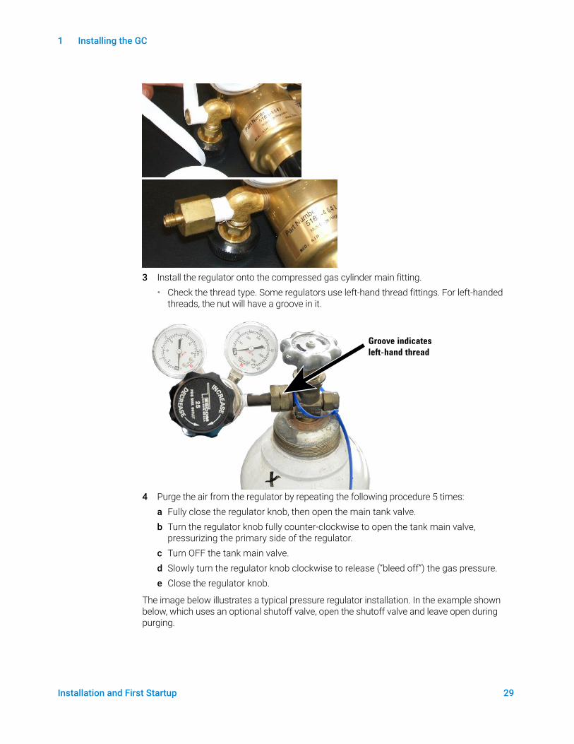
3 Install the regulator onto the compressed gas cylinder main fitting. • Check the thread type. Some regulators use left-hand thread fittings. For left-handed
threads, the nut will have a groove in it.
4 Purge the air from the regulator by repeating the following procedure 5 times:a Fully close the regulator knob, then open the main tank valve.b Turn the regulator knob fully counter-clockwise to open the tank main valve,
pressurizing the primary side of the regulator.c Turn OFF the tank main valve.d Slowly turn the regulator knob clockwise to release (“bleed off”) the gas pressure. e Close the regulator knob.
The image below illustrates a typical pressure regulator installation. In the example shown below, which uses an optional shutoff valve, open the shutoff valve and leave open during purging.
Groove indicates
left-hand thread
1 Installing the GC
30 Installation and First Startup
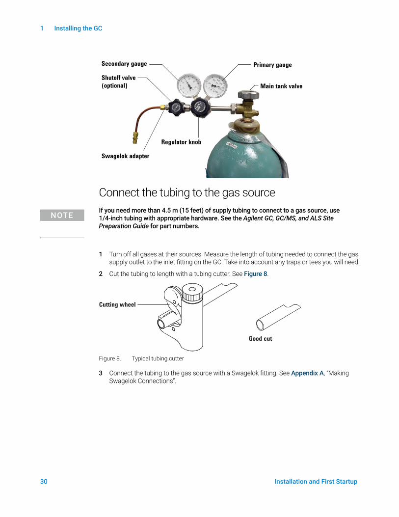
Connect the tubing to the gas source
NOTEIf you need more than 4.5 m (15 feet) of supply tubing to connect to a gas source, use 1/4-inch tubing with appropriate hardware. See the Agilent GC, GC/MS, and ALS Site Preparation Guide for part numbers.
1 Turn off all gases at their sources. Measure the length of tubing needed to connect the gas supply outlet to the inlet fitting on the GC. Take into account any traps or tees you will need.
2 Cut the tubing to length with a tubing cutter. See Figure 8.
Figure 8. Typical tubing cutter
3 Connect the tubing to the gas source with a Swagelok fitting. See Appendix A, “Making Swagelok Connections”.
Main tank valve
Primary gaugeSecondary gauge
Shutoff valve
(optional)
Regulator knob
Swagelok adapter
Cutting wheel
Good cut
1 Installing the GC
Installation and First Startup 31
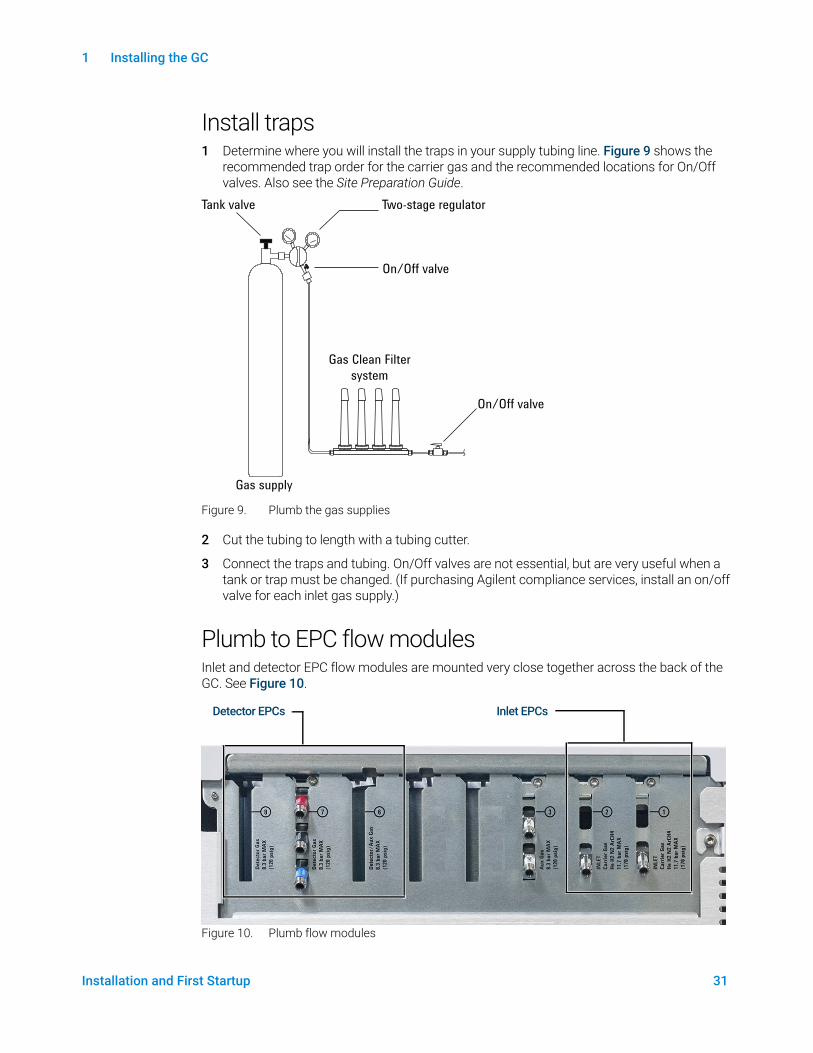
Install traps1 Determine where you will install the traps in your supply tubing line. Figure 9 shows the
recommended trap order for the carrier gas and the recommended locations for On/Off valves. Also see the Site Preparation Guide.
Figure 9. Plumb the gas supplies
2 Cut the tubing to length with a tubing cutter.
3 Connect the traps and tubing. On/Off valves are not essential, but are very useful when a tank or trap must be changed. (If purchasing Agilent compliance services, install an on/off valve for each inlet gas supply.)
Plumb to EPC flow modulesInlet and detector EPC flow modules are mounted very close together across the back of the GC. See Figure 10.
Figure 10. Plumb flow modules
Tank valve
Gas supply
Two-stage regulator
Gas Clean Filter system
On/Off valve
On/Off valve
Detector EPCs Inlet EPCs

1 Installing the GC
32 Installation and First Startup
Purge the supply lines for a few minutes before connecting them to the GC flow modules.
WARNINGBe sure to vent uncombusted hydrogen to a fume hood or other safe location.
When two inlets use the same carrier gas, we recommend using a Tee fitting that includes shutoff valves for performing leak tests.
When two detectors use the same gases, we recommend using a Tee fitting. Shutoff valves are not required.
TCD connections The carrier gas and reference gas must come from the same source. Because of the close spacing of the EPC modules, the simplest way to do this is to attach lengths of tubing to each input to bring the ends outside the back panel, then join them with a Tee.
Side mounted detector connections If the GC is equipped with a side-mounted TCD or ECD, attach the carrier gas to the single gas connection at the back of the side mount enclosure. (For TCD, an internal Tee feeds the reference gas and input.)
Install Aux EPC module frits for your applicationSkip this section if an Aux EPC module is not installed.
The AUX EPC module ships with brown (FID air) restrictors in all channels. For certain applications, you will have to replace this restrictor (frit) so the EPC module can provide flows in the correct ranges. See Table 5. Also refer to the other instrument’s or application’s documentation.
Notes for this table• Frit G3430-80061 ships in each AUX channel.
• Restrictor kit G3470-60502 is included in the AUX module ship kit.
• Always use new O-rings (part number 5181-3344, O-rings, 6/pk).
• Install tubing and connectors as needed for each additional gas supply required.
Table 5 G3470-60502 Aux EPC restrictor kit
Kit contains Part number Marking Flow Resistance Often used with
O-rings, 6/pk 5181-3344
None G3430-80061 1 ringBrown
400 ± 30 SCCM air @ 40 psig
Low FID air, purged splitters, Deans switch
3 G3430-80062 2 ringsRed
30 ± 1.5 SCCM H2 @ 15 psig
Medium FID hydrogen
3 G3430-80063 3 ringsBlue
3.33 ± 0.3 SCCM H2 @ 15 psig
High NPD hydrogen
3 G3430-20011 None Zero (none) Purged splitter, Deans switch when using backflush

1 Installing the GC
Installation and First Startup 33
• Do not install an external flow restrictor.
1 Installing the GC
34 Installation and First Startup
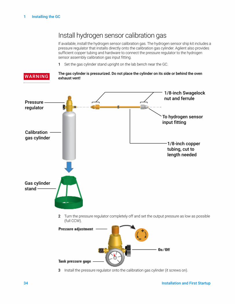
Install hydrogen sensor calibration gasIf available, install the hydrogen sensor calibration gas. The hydrogen sensor ship kit includes a pressure regulator that installs directly onto the calibration gas cylinder. Agilent also provides sufficient copper tubing and hardware to connect the pressure regulator to the hydrogen sensor assembly calibration gas input fitting.
1 Set the gas cylinder stand upright on the lab bench near the GC.
WARNINGThe gas cylinder is pressurized. Do not place the cylinder on its side or behind the oven exhaust vent!
2 Turn the pressure regulator completely off and set the output pressure as low as possible (full CCW).
3 Install the pressure regulator onto the calibration gas cylinder (it screws on).
1/8-inch Swagelock nut and ferrule
To hydrogen sensor input fitting
1/8-inch copper tubing, cut to length needed
Pressure regulator
Calibration gas cylinder
Gas cylinder stand

1 Installing the GC
Installation and First Startup 35
4 Connect the calibration gas cylinder output tubing to the hydrogen sensor module.• Use the tubing, nuts, and ferrules provided in the hydrogen sensor kit.• See the figure under step 1.
5 Install the calibration gas cylinder into the stand and secure using the screw.
6 Turn on the supply pressure at the pressure regulator. (You will adjust it later.)
7 Check for leaks in the fittings using a leak detection fluid. Correct any leaks.
1 Installing the GC
36 Installation and First Startup
Step 9 Leak test all connections and set source pressures
Liquid leak detectors, such as soapy water, are not recommended, especially in areas where cleanliness is very important. If there is a leak, these liquids can contaminate the plumbing and affect your analyses. If you do use leak detection fluid, immediately rinse the fitting to remove the soapy film.
When checking for leaks of hydrogen or helium, Agilent recommends the G3388B leak detector, or similar.
WARNINGTo avoid a potential shock hazard when using liquid detection fluid, turn the GC off and disconnect the main power cord. Be careful not to spill leak solution on electrical leads.
Perform a pressure drop test.
1 Turn off the GC.
2 Set the regulator pressure to 415 kPa (60 psi).
3 Fully turn the regulator pressure adjustment knob counterclockwise to shut the valve.
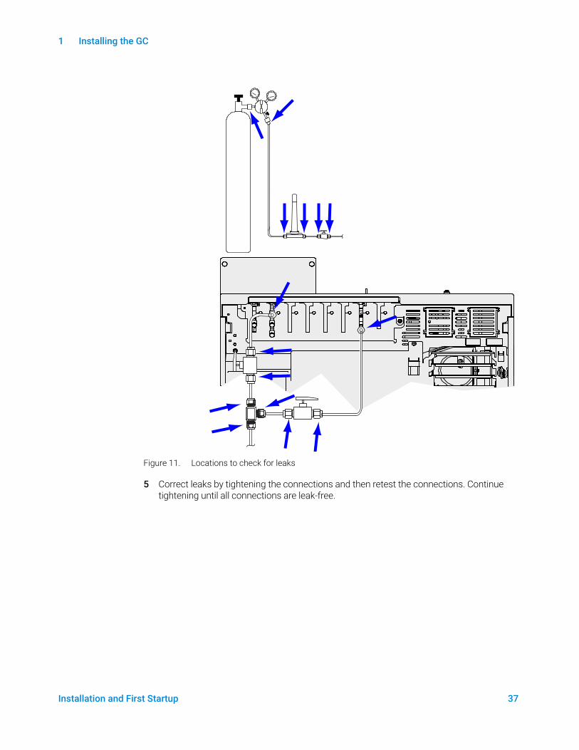
4 Wait 10 min. If there is a pressure loss greater than 7 kPa (1 psi), there is a leak in the external connections. Use the leak detector to check each fitting for leaks. See Figure 11.
1 Installing the GC
Installation and First Startup 37
Figure 11. Locations to check for leaks
5 Correct leaks by tightening the connections and then retest the connections. Continue tightening until all connections are leak-free.

1 Installing the GC
38 Installation and First Startup
Set source gas pressuresThe pressure set at a tank regulator depends on these factors:
• The inlet pressure needed to achieve the highest column flow rate required by your method.
The pressure/flow relationship depends on the column or device involved. The best way to address this is to begin at a moderate pressure level and adjust upward as needed.
• A pressure difference of about 170 kPa (25 psi) across flow controlling devices enables them to work properly.
• The pressure limit of the weakest part of the supply system.
Swagelok fittings and copper tubing are more than adequate for the highest pressures used in gas chromatography.
We recommend a maximum continuous operating pressure of 1170 kPa (170 psi) to avoid excessive wear and leaks.
Traps are often the weakest part of the system. They should be labeled, either on the trap itself or in accompanying literature, with a maximum operating pressure. Source pressure must not exceed the lowest maximum operating pressure in the supply system.
Table 6 suggests starting values of source pressure.
Table 6 Suggested starting pressures
Gas Use Source pressure
Carrier Packed column 410 kPa (60 psi)
Capillary columns 550 kPa (80 psi)
Air for FID, FPD Detectors 550 kPa (80 psi)
Hydrogen Detectors 410 kPa (60 psi)
Makeup gas Detectors 410 kPa (60 psi)
TCD Reference TCD 410 kPa (60 psi)
Air for valve actuators Valves 345 kPa (50 psi)

1 Installing the GC
Installation and First Startup 39
Step 10 Install inlet checkout parts
If using a split/splitless inlet, install the liner and O-ring needed for checkout. See the Operation manual, and the procedures listed in Maintaining Your GC.
If installing a GC/MS system, refer to the GC/MS installation manuals for the correct inlet hardware to install, as needed.

1 Installing the GC
40 Installation and First Startup
Step 11 Install ALS, if ordered
If installing an ALS, install it now. Refer to its instructions.
Prepare the sampler for checkout. See the checkout procedures and information in the Operation Manual.
1 Prepare a 2-mL screw-top sample vial with checkout sample.
2 Prepare 4-mL waste vials and place them into the turret.
3 Prepare fresh solvent solutions as needed for the checkout sample for your detector type. Place the solvent vials into the injector turret. For details on the solvent needed, see the Operation Manual:
1 Installing the GC
Installation and First Startup 41
Step 12 Configuring GC-MSD communications
If connected to an MSD such as 5977A or 7000C/D, use the GC touchscreen to identify the connected MSD’s IP address and to select the part information (for example, source type, and pump type). Select the GC IP config page, and then the MSD Config tab. The MSD IP address entered here must exactly match the IP address entered in the data system and at the MSD keyboard.
Once the instruments have IP addresses and are connected to the LAN, complete the GC/MS configuration and enable enhanced communications, Parts Finder data, and MS-friendly features such as the MS Vent method as follows:
1 Select the GC IP config page, and then the MSD Config tab.
2 If configuring a 5977B MSD, select LCOMM from the dropdown menu under Connection Type, and input the MSD’s IP Address, Gateway, and Net Mask. Otherwise, select DCOMM and input the MSD’s IP address.
3 Enter details for the MSD.
1 Installing the GC
42 Installation and First Startup
Step 13 Connect the external cables
In addition to the LAN cable as referenced in “Connect GC to LAN, Local Computer, or Tablet” on page 22, other cables may be installed for control of the GC’s automatic liquid sampler (ALS), connecting signal output to integrators, synchronizing the start and end of a run between various instruments, sensing conditions external to the GC, and controlling devices external to the GC.
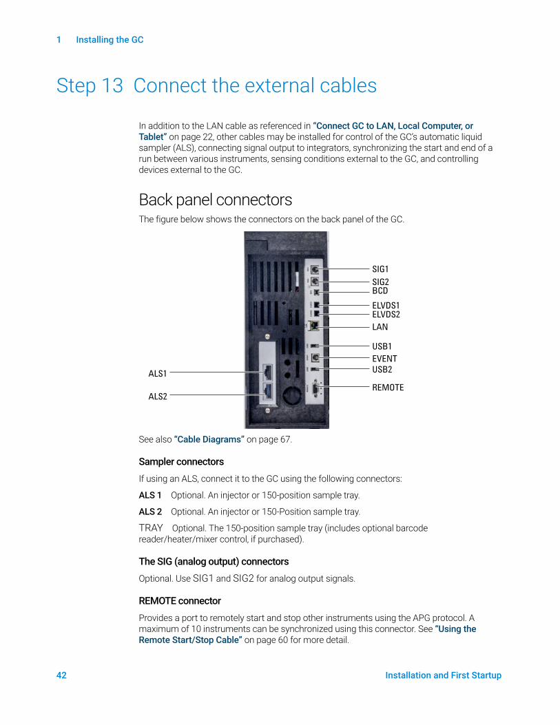
Back panel connectorsThe figure below shows the connectors on the back panel of the GC.
See also “Cable Diagrams” on page 67.
Sampler connectors
If using an ALS, connect it to the GC using the following connectors:
ALS 1 Optional. An injector or 150-position sample tray.
ALS 2 Optional. An injector or 150-Position sample tray.
TRAY Optional. The 150-position sample tray (includes optional barcode reader/heater/mixer control, if purchased).
The SIG (analog output) connectors
Optional. Use SIG1 and SIG2 for analog output signals.
REMOTE connector
Provides a port to remotely start and stop other instruments using the APG protocol. A maximum of 10 instruments can be synchronized using this connector. See “Using the Remote Start/Stop Cable” on page 60 for more detail.
ALS1
ALS2
SIG1SIG2
REMOTE
EVENT
BCD
LAN
ELVDS1ELVDS2
USB1
USB2
1 Installing the GC
Installation and First Startup 43
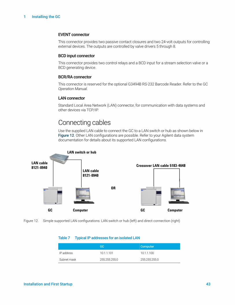
EVENT connector
This connector provides two passive contact closures and two 24-volt outputs for controlling external devices. The outputs are controlled by valve drivers 5 through 8.
BCD input connector
This connector provides two control relays and a BCD input for a stream selection valve or a BCD generating device.
BCR/RA connector
This connector is reserved for the optional G3494B RS-232 Barcode Reader. Refer to the GC Operation Manual.
LAN connector
Standard Local Area Network (LAN) connector, for communication with data systems and other devices via TCP/IP.
Connecting cablesUse the supplied LAN cable to connect the GC to a LAN switch or hub as shown below in Figure 12. Other LAN configurations are possible. Refer to your Agilent data system documentation for details about its supported LAN configurations.
Figure 12. Simple supported LAN configurations: LAN switch or hub (left) and direct connection (right)
LAN switch or hub
LAN cable
8121-0940Crossover LAN cable 5183-4648
GC GCComputer Computer
LAN cable
8121-0940
OR
Table 7 Typical IP addresses for an isolated LAN
GC Computer
IP address 10.1.1.101 10.1.1.100
Subnet mask 255.255.255.0 255.255.255.0

1 Installing the GC
44 Installation and First Startup
A single LAN communications cable is supplied with the GC. The switch (or hub) and other cables must be ordered separately, if needed. See Table 8 and Table 9 for cabling requirements for other configurations.
Table 8 Cabling requirements
8860 Series GC connected to: Required Cable(s) Part number
Samplers
7693A Automatic Liquid Sampler Injector cable or tray cable G4514-60610
7650 Automatic Liquid Sampler Injector cable G4514-60610
7683 Automatic Liquid Sampler Injector cable is integral Tray cable G2614-60610
7697A Headspace Sampler Remote, 9-pin male/6-pin connector G1530-60930
G1289B/G1290B Headspace Sampler Remote, 9-pin male/6-pin connector G1530-60930
CTC automatic sampler Cable, 4 conductor, remote start G6500-82013
Mass Spectrometers and MS systems
Mass Selective Detector Remote, 2-m, 9-pin male/9-pin male G1530-61200
GC / Agilent external sampler / MS or MSD system (for example, GC/HS/MSD or GC/Thermal Desorber/MSD)
Y-Cable, remote start/stop G1530-61200
GC / TMS-9800/ MS or MSD system Y-Cable, remote start/stopInterface cable for Agilent 6890/7890/8890 to P&T
G1530-6120014-6689-086
Integrators
3395B/3396C Integrator Remote, 9 pin/15 pinAnalog, 2 m, 6 pin
03396-61010G1530-60570
Non-Agilent Integrator General purpose analog signal cable 2 m, 6 pin G1530-60560
Non-Agilent data system General use remote,9-pin male/spade lugs(various lengths)
35900-60670 (2 m), 35900-60920 (5 m),35900-60930 (0.5 m)
Other devices
Non-Agilentinstrument, unspecified
External event, 8 pin/spade lugs (No label. See “Labeling BCD and EVENT cables” on page 56.)
G1530-60590
Valco pulser module (used with PDHID) Valve pulser module power supply cable (includes green EVENT label)
G1580-60730
Stream selection valvesGas sampling valves (external)
See documentation accompanying the valve
External valve cable (includes green EVENT label) G1580-60710
LAN
LAN Cable, networking CAT 5, 25 feetCable, LAN, crossover
8121-09405183-4648

1 Installing the GC
Installation and First Startup 45
GC / MS / Agilent data system / ALS
Additional cabling configurationsFor additional cabling configurations, see Appendix B, “Cabling Diagrams and Remote Start/Stop”.
Table 9 Cabling for other instruments in a 8860 Series GC system
Instrument 1 Instrument 2 Type of cable Part number
Mass Selective Detector Purge & trap, thermal desorber, or headspace sampler
Splitter (“Y”) cable for remote start/stop, 1 male and 2 female connectors
G1530-61200
Splitter (“H”) cable for APG remote, 2 male and 2 female connectors
35900-60800
LAN switch or hub1. LAN cable
8121-0940
GC ComputerMSD
2. APG Remote Cable,
G1530-61200
1. LAN cable
8121-0940
1. LAN cable
8121-0940
Table 10 Cables for a typical GC/MSD or GC/MS system
Number Part number and description
1 G1530-61200, 2-m APG remote cable, 9-pin male/9-pin male
2 8121-0940, Cable, LAN, 25 foot
1 Installing the GC
46 Installation and First Startup
Step 14 Vent ECD or uncombusted hydrogen to a fume hood
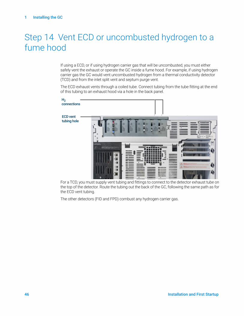
If using a ECD, or if using hydrogen carrier gas that will be uncombusted, you must either safely vent the exhaust or operate the GC inside a fume hood. For example, if using hydrogen carrier gas the GC would vent uncombusted hydrogen from a thermal conductivity detector (TCD) and from the inlet split vent and septum purge vent.
The ECD exhaust vents through a coiled tube. Connect tubing from the tube fitting at the end of this tubing to an exhaust hood via a hole in the back panel.
For a TCD, you must supply vent tubing and fittings to connect to the detector exhaust tube on the top of the detector. Route the tubing out the back of the GC, following the same path as for the ECD vent tubing.
The other detectors (FID and FPD) combust any hydrogen carrier gas.
ECD vent tubing hole
H2 connections

1 Installing the GC
Installation and First Startup 47
Step 15 Connect valve actuator air (if present)
Valves are driven by air actuators. Valves should have a dedicated air source; they cannot share detector air supplies.
CAUTIONDo not share air between a detector and valves.
Valves can use nitrogen as an alternate supply. In this case, the nitrogen does not have to be chromatographic grade but must be free from contaminants.
Valve actuator air is supplied through 1/4-inch plastic tubing. If your GC was ordered with valves, the plastic tubing will already be attached to the actuators and will extend from the back of the GC. Additional valves are shipped with a 1/4 to 1/8-inch reducing union to be used in plumbing.
CAUTIONRoute the tubing away from the oven exhaust. The hot air will melt the plastic tubing.
Turn off the air supply at the source. If needed, shorten the supplied plastic tubing using a sharp knife. Connect the tubing to the air source using a 1/4-inch Swagelok nut and ferrules. See Figure 13.
Figure 13. Valve actuator air tubing
Hole for actuator air tubing
1 Installing the GC
48 Installation and First Startup
Step 16 Configure the checkout column
You must configure the consumable items (such as the checkout column).
Checkout columnThe column length, inside diameter, and film thickness are on a metal tag attached to the column.
1 Select Method > Configuration > Columns.
2 Double-click or double-tap in the column row (or in the next empty row). When prompted, enter the column details, such as dimensions, type, temperatures, and so on. Select OK to accept the entries.
3 Use the drop-down lists to select the column's Inlet, Outlet, and Heated By values. (See the descriptions below.)
This completes configuration for a single capillary column. Also see the Operation manual for more information about configuring columns.

1 Installing the GC
Installation and First Startup 49
Step 17 Install the checkout column
A capillary column was shipped with the GC to be used to confirm proper operation. Agilent suggests that it be used only for that purpose.
Before use, the column must be conditioned to remove any contaminants.
1 Locate the installation instructions for the column, inlet, and detector you will use. Refer to the Maintaining Your GC manual. See to the sections on your specific inlet and detector types:
2 Install the column in the inlet.
3 Connect the free end of the column to the detector, as described in Maintaining Your GC.
4 Turn on the carrier gas.
5 If using a split/splitless inlet, perform an Inlet Leak Check. Select Diagnostics > Diagnostic Test, select Inlet #, then select Leak & Restriction Test. Press Start Test to begin the check. If the check fails, tighten connections.
6 Set the oven temperature and inlet flow conditions specified for conditioning the column. Select Method to access current GC temperatures and flows.• Set the oven temperature to 20 °C higher than the highest checkout method
temperature (do not exceed the column maximum temperature). For example, for FID checkout set the oven temperature to 210 °C.
• Set the detector temperature to 20 °C higher than the checkout method temperature. For example, for FID checkout set the detector temperature to 320 °C.
7 Turn the detector gases on. Light the flame, if appropriate.
8 Heat the detector to the temperature given in the bakeout instructions, and hold at temperature for the time given in the instructions.
1 Installing the GC
50 Installation and First Startup
Step 18 Transfer the checkout sample to a screw-top sample vial
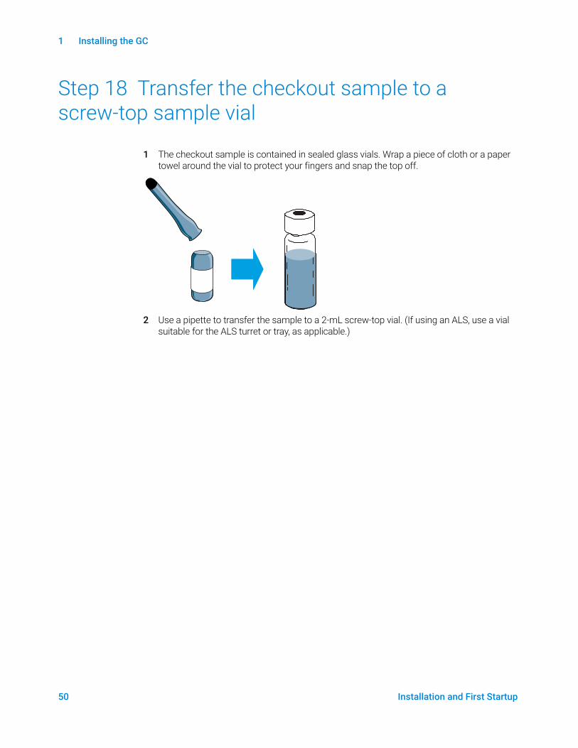
1 The checkout sample is contained in sealed glass vials. Wrap a piece of cloth or a paper towel around the vial to protect your fingers and snap the top off.
2 Use a pipette to transfer the sample to a 2-mL screw-top vial. (If using an ALS, use a vial suitable for the ALS turret or tray, as applicable.)

1 Installing the GC
Installation and First Startup 51
Step 19 When the system stabilizes, run one injection
Perform the checkout procedure as described in the Operation Manual.
1 Enter the parameters for the checkout procedure.• If using an Agilent data system, use it to create a checkout method.• If not using a data system, enter the setpoints using the Browser Interface.
2 When the GC is ready to begin a run, the Touchscreen status shows STATUS: NORMAL READY (alternately, when the component of the GC is not ready to begin a run, the touchscreen shows STATUS: NOT READY), make the injection and start the run.
For a manual injection, inject the sample and press Prep Run .
3 Evaluate results by comparing the chromatogram you generated with the one in the checkout procedure. There should be a close resemblance.
1 Installing the GC
52 Installation and First Startup
Step 20 Prepare for the Next Analysis
After evaluating the GC under the checkout conditions, installation checkout is complete. The next step is to prepare the GC for your next analysis. Be sure to cool the GC before making changes.
1 Cool all heated zones to < 40 °C, and set safe gas flows. Place the GC in maintenance mode: Maintenance > Instrument > Perform Maintenance > Maintenance Mode > Start Maintenance and wait for the GC to become ready.
2 Turn off the power by pressing the On/Off switch.
3 Shut off all gas valves at the gas source.
4 When the GC is cool, do the following:• Install the appropriate inlet hardware (can include septum, liner, liner-O-ring, inlet gold
seal, inserts, and so on).• Install the appropriate detector hardware (wavelength filter for FPD+, jet for FID or NPD).• Change to any alternate gas sources as needed for the new analysis.• Install the desired column and condition it per the manufacturer’s recommendations.• Configure the GC to match any hardware or gas type changes (columns, liners, carrier or
makeup gas types, and so on).• Load or create the desired method.

Installation and First Startup 53
A Making Swagelok ConnectionsMaking Swagelok Connections 54
Using a Swagelok Tee 57
The gas supply tubing is attached with Swagelok fittings. If you are not familiar with Swagelok connections, review the following procedures.
A Making Swagelok Connections
54 Installation and First Startup
Making Swagelok ConnectionsObjective
To make a tubing connection that does not leak and that can be taken apart without damaging the fitting.
Materials needed
• 1/8-inch (or 1/4-inch, if used) preconditioned copper tubing
• 1/8-inch (or 1/4-inch, if used) Swagelok nuts
• Front and back ferrules
• Two 7/16-inch (for 1/8-inch nuts) or 9/16-inch (for 1/4-inch nuts) wrenches
Procedure
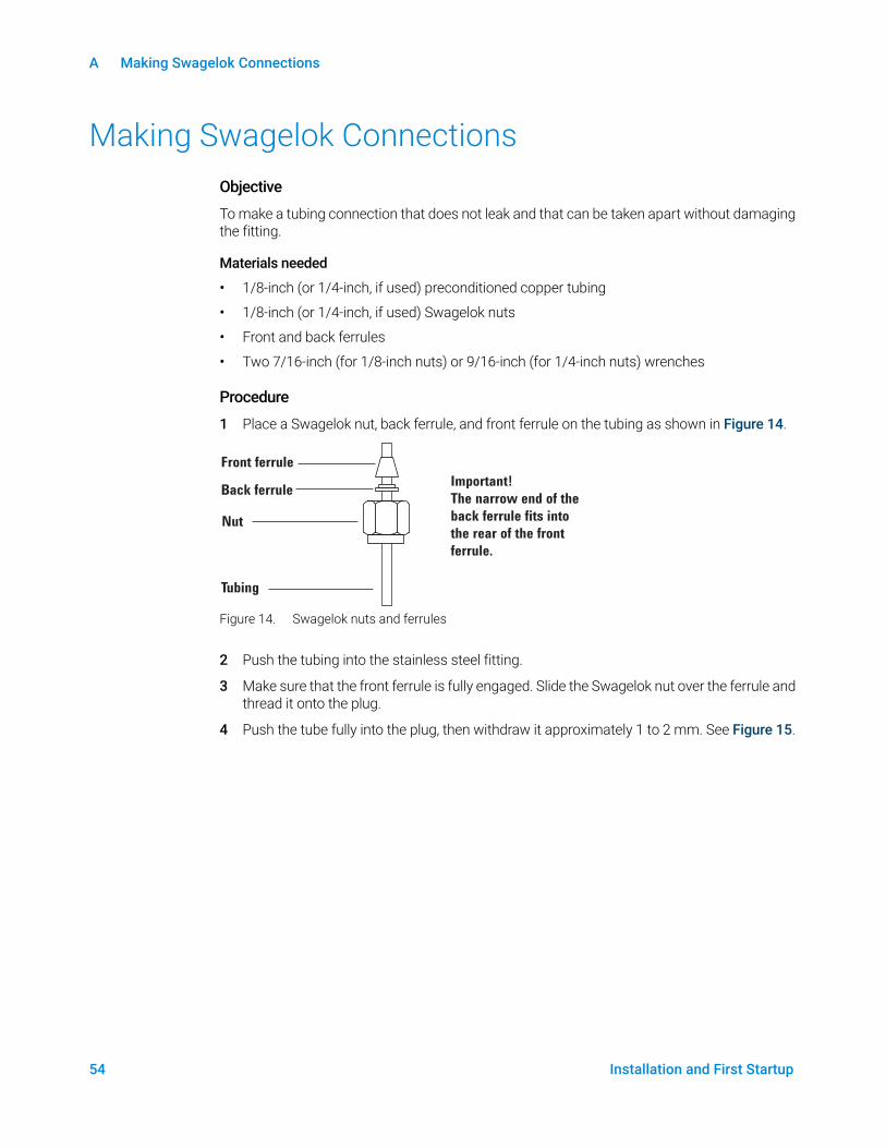
1 Place a Swagelok nut, back ferrule, and front ferrule on the tubing as shown in Figure 14.
Figure 14. Swagelok nuts and ferrules
2 Push the tubing into the stainless steel fitting.
3 Make sure that the front ferrule is fully engaged. Slide the Swagelok nut over the ferrule and thread it onto the plug.
4 Push the tube fully into the plug, then withdraw it approximately 1 to 2 mm. See Figure 15.
Front ferrule
Back ferrule
Nut
Tubing
Important!
The narrow end of the
back ferrule fits into
the rear of the front
ferrule.
A Making Swagelok Connections
Installation and First Startup 55
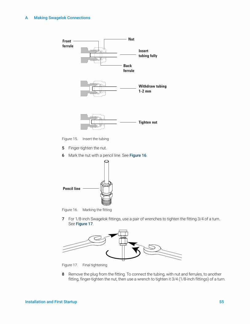
Figure 15. Insert the tubing
5 Finger-tighten the nut.
6 Mark the nut with a pencil line. See Figure 16.
Figure 16. Marking the fitting
7 For 1/8-inch Swagelok fittings, use a pair of wrenches to tighten the fitting 3/4 of a turn. See Figure 17.
Figure 17. Final tightening
8 Remove the plug from the fitting. To connect the tubing, with nut and ferrules, to another fitting, finger-tighten the nut, then use a wrench to tighten it 3/4 (1/8-inch fittings) of a turn.
Front
ferrule
Back
ferrule
Nut
Insert
tubing fully
Withdraw tubing
1-2 mm
Tighten nut
Pencil line
A Making Swagelok Connections
56 Installation and First Startup
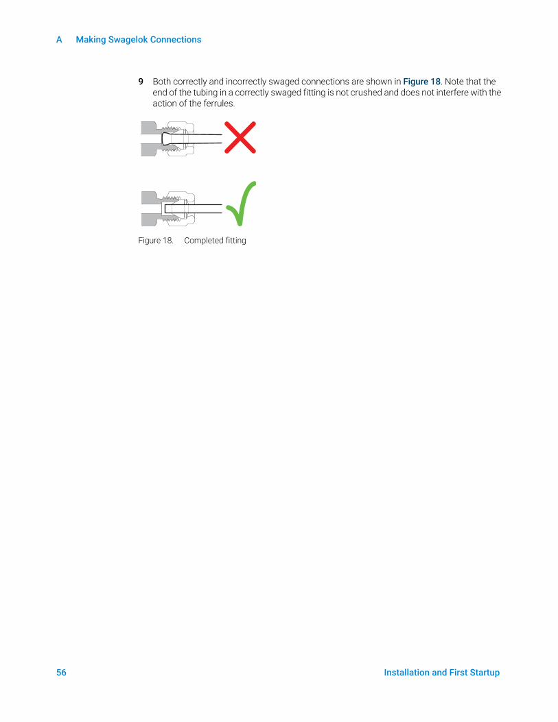
9 Both correctly and incorrectly swaged connections are shown in Figure 18. Note that the end of the tubing in a correctly swaged fitting is not crushed and does not interfere with the action of the ferrules.
Figure 18. Completed fitting
A Making Swagelok Connections
Installation and First Startup 57
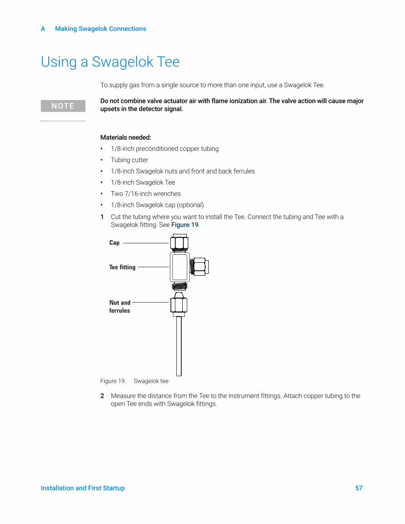
Using a Swagelok TeeTo supply gas from a single source to more than one input, use a Swagelok Tee.
NOTEDo not combine valve actuator air with flame ionization air. The valve action will cause major upsets in the detector signal.
Materials needed:
• 1/8-inch preconditioned copper tubing
• Tubing cutter
• 1/8-inch Swagelok nuts and front and back ferrules
• 1/8-inch Swagelok Tee
• Two 7/16-inch wrenches
• 1/8-inch Swagelok cap (optional)
1 Cut the tubing where you want to install the Tee. Connect the tubing and Tee with a Swagelok fitting. See Figure 19.
Figure 19. Swagelok tee
2 Measure the distance from the Tee to the instrument fittings. Attach copper tubing to the open Tee ends with Swagelok fittings.
Cap
Tee fitting
Nut and
ferrules

A Making Swagelok Connections
58 Installation and First Startup
B Cabling Diagrams and Remote Start/Stop
Installation and First Startup 59
B Cabling Diagrams and Remote Start/StopUsing the Remote Start/Stop Cable 60
Multi-instrument Cabling Examples 63
Cable Diagrams 67
This section lists cabling requirements and connection diagrams that apply to less common or specialized GC installations.
B Cabling Diagrams and Remote Start/Stop
60 Installation and First Startup
Using the Remote Start/Stop CableRemote start/stop is used to synchronize two or more instruments. For example, you might connect an integrator and the GC so that the Start/Stop buttons on either instrument control both of them. You can synchronize a maximum of ten instruments using Remote cables.
Connecting Agilent productsIf connecting two Agilent products with Remote cables, the sending and receiving circuits will be compatible—just plug in both ends of the cable.
Connecting non-Agilent productsIf connecting to a non-Agilent product, the following paragraphs contain information you will need to ensure compatibility.
APG Remote signal electrical specifications
The APG signals are a modified open collector type. The signal levels are generally TTL levels (low voltage is logic zero, high voltage is logic one) but the open circuit voltage will be between 2.5 and 3.7 V. The typical voltage is 3 V. A voltage over 2.2 V will be interpreted as a high logic state while a voltage below 0.4 V will be interpreted as a low logic state. These levels provide some margin over the specifications of the devices used.
The pull-up resistance, connected to the open-circuit voltage, is in the range of about 1 kOhms to 1.5 kOhms. For a logic-low state, for a single device on the bus, the minimum current you must be able to sink is 3.3 mA. Since devices are connected in parallel, when you have multiple devices this minimum current must be multiplied by the number of devices attached on the bus. The maximum voltage for a low-input state is 0.4 V.
The bus is passively pulled high. Leakage current out of a port must be less than 0.2 mA to keep the voltage from being pulled lower than 2.2 V. Higher leakage current may cause the state to be interpreted as a low.
Over-voltage protection: APG Remote connections are clamped by a zener diode to 5.6 V. Exceeding this voltage will damage the circuit (GC logic board).
APG Remote - Suggested drive circuits
A signal on the APG bus may be driven by another APG device or by one of the following circuits:
• A relay, with one side connected to ground, when closed will set a logic-low state.
• An NPN transistor, with the emitter connected to ground and the collector connected to the signal line will set a logic-low state if proper base current is supplied.
• An open-collector logic gate will perform this same function.
• A low-side drive IC will also work, but Darlington-type drivers should be avoided as they will not meet the low-side voltage requirement of less than 0.4 V
B Cabling Diagrams and Remote Start/Stop
Installation and First Startup 61
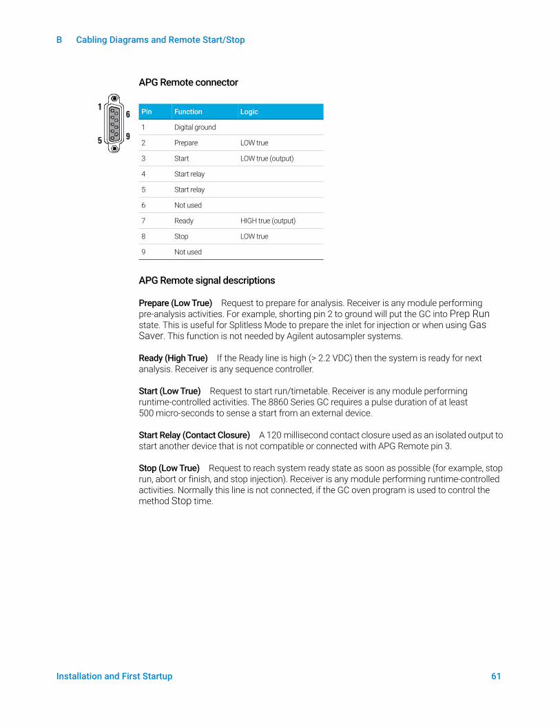
APG Remote connector
APG Remote signal descriptions
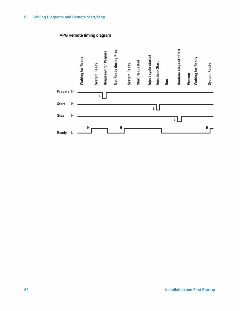
Prepare (Low True) Request to prepare for analysis. Receiver is any module performing pre-analysis activities. For example, shorting pin 2 to ground will put the GC into Prep Run state. This is useful for Splitless Mode to prepare the inlet for injection or when using Gas Saver. This function is not needed by Agilent autosampler systems.
Ready (High True) If the Ready line is high (> 2.2 VDC) then the system is ready for next analysis. Receiver is any sequence controller.
Start (Low True) Request to start run/timetable. Receiver is any module performing runtime-controlled activities. The 8860 Series GC requires a pulse duration of at least 500 micro-seconds to sense a start from an external device.
Start Relay (Contact Closure) A 120 millisecond contact closure used as an isolated output to start another device that is not compatible or connected with APG Remote pin 3.
Stop (Low True) Request to reach system ready state as soon as possible (for example, stop run, abort or finish, and stop injection). Receiver is any module performing runtime-controlled activities. Normally this line is not connected, if the GC oven program is used to control the method Stop time.
Pin Function Logic
1 Digital ground
2 Prepare LOW true
3 Start LOW true (output)
4 Start relay
5 Start relay
6 Not used
7 Ready HIGH true (output)
8 Stop LOW true
9 Not used
1
5
6
9
B Cabling Diagrams and Remote Start/Stop
62 Installation and First Startup
APG Remote timing diagram
Prepare H
Start H
Stop H
Ready L
Wait
ing
for
Ready
Sys
tem
Ready
Requesw
t fo
r P
repare
Sys
tem
Ready
Not
Ready
duri
ng
Pre
p
Sta
rt R
equeste
d
Inje
ct
cyc
le s
tart
ed
Inje
cti
on
/S
tart
Ru
n
Runti
me e
lapsed/
Sta
rt
Postr
un
Wait
ing
for
Ready
Sys
tem
Ready
L
L
L
HHH

B Cabling Diagrams and Remote Start/Stop
Installation and First Startup 63
Multi-instrument Cabling Examples
GC / ALS / Non-Agilent Data System
Number Part number and description
1 G1530-60930, General use APG remote cable, 9-pin male/spade lug (0.5m)
2 G1530-60590, External event cable, 8-pin/spade lugs
GC/ALS
1. APG Remote Cable,
G1530-60930
2. External event cable,
8 pin/spade lugs, G1530-60590
35900-60670 APG remotecable spade lug identification
G1530-60590 External eventcable spade lug identification
Connector 1 9 pin (male)
Signal name Connector 2 spade lugs
Pin Color Signal
1 GND Black 1 Yellow 24 V Out
2 Prepare White 2 Black 24 V Out 2
3 Start Red 3 Red Ground
4 Shut down Green 4 White Ground
5 Reserved Brown 5 Orange Contact 1
6 Power on Blue 6 Green Contact 1
7 Ready Orange 7 Brown Contact 2
8 Stop Yellow 8 Blue Contact 2
9 Start Request Violet 9
B Cabling Diagrams and Remote Start/Stop
64 Installation and First Startup
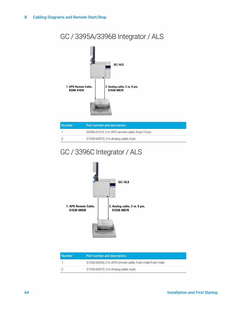
GC / 3395A/3396B Integrator / ALS
GC / 3396C Integrator / ALS
Number Part number and description
1 03396-61010, 2-m APG remote cable, 9-pin/15-pin
2 G1530-60570, 2-m Analog cable, 6-pin
Number Part number and description
1 G1530-60930, 2-m APG remote cable, 9-pin male/9-pin male
2 G1530-60570, 2-m Analog cable, 6-pin
GC/ALS
1. APG Remote Cable,
03396-61010
2. Analog cable, 2-m, 6 pin,
G1530-60570
GC/ALS
1. APG Remote Cable,
G1530-60930
2. Analog cable, 2-m, 6 pin,
G1530-60570
B Cabling Diagrams and Remote Start/Stop
Installation and First Startup 65
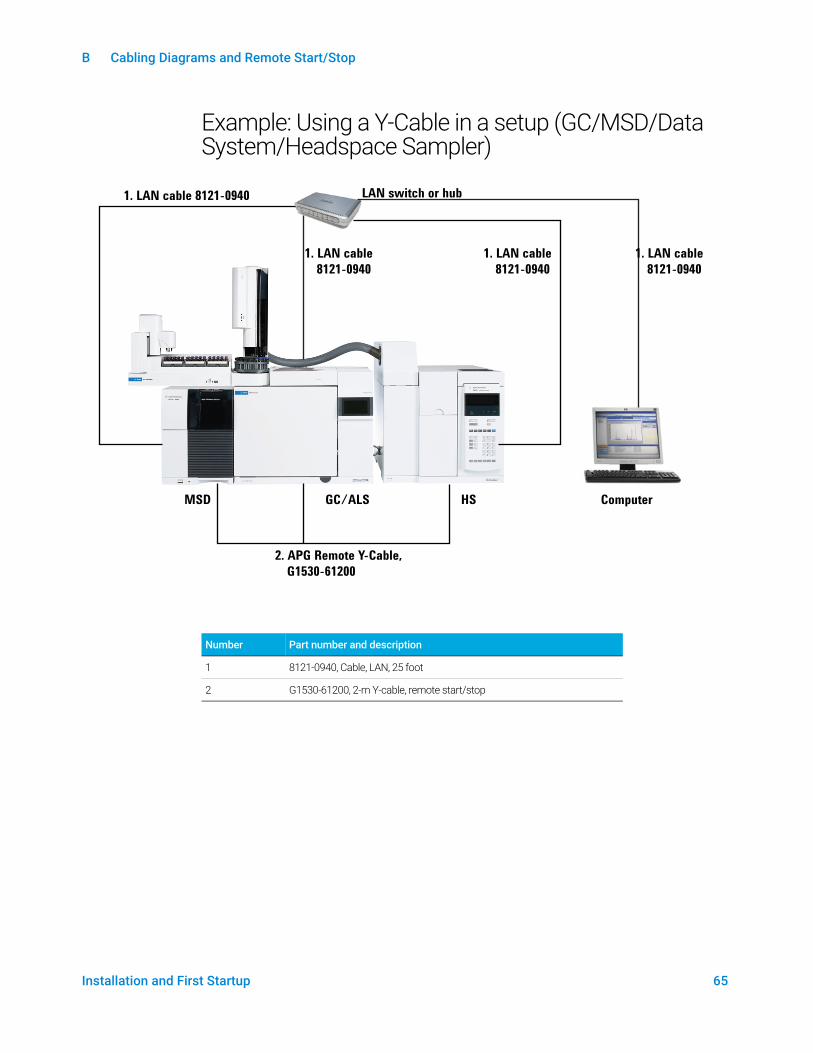
Example: Using a Y-Cable in a setup (GC/MSD/Data System/Headspace Sampler)
LAN switch or hub1. LAN cable 8121-0940
GC/ALS ComputerHS
2. APG Remote Y-Cable,
G1530-61200
1. LAN cable
8121-0940
1. LAN cable
8121-0940
1. LAN cable
8121-0940
MSD
Number Part number and description
1 8121-0940, Cable, LAN, 25 foot
2 G1530-61200, 2-m Y-cable, remote start/stop

B Cabling Diagrams and Remote Start/Stop
66 Installation and First Startup
GC / External Events (unspecified, non-Agilent instrument)
Number Part number and description
1 G1530-60590, External events cable, 8-pin/spade lugs
GC/ALS
1. External event cable,
8 pin/spade lugs,
G1530-60590
Connector Signal name Maximum rating Wire color Corresponds to valve #
24 volt control output
1 24 volt output 1 150 mA output Yellow 5
2 24 volt output 2 150 mA output Black 6
3 Ground Red
4 Ground White
Relay contact closures (normally open)
5 Contact closure 1 48 V AC/DC, 250 mA Orange 7
6 Contact closure 1 Green 7
7 Contact closure 2 48 V AC/DC, 250 mA Brown or violet 8
8 Contact closure 2 Blue 8
B Cabling Diagrams and Remote Start/Stop
Installation and First Startup 67
Cable Diagrams
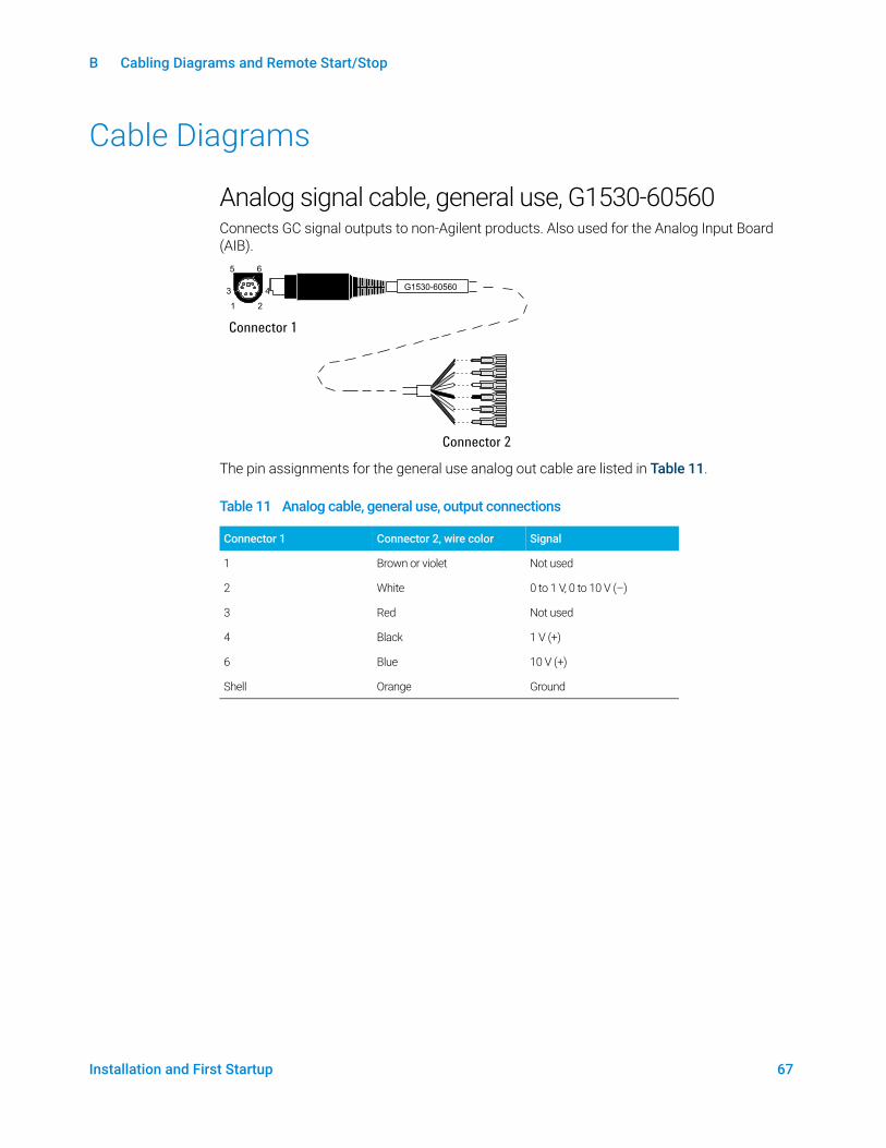
Analog signal cable, general use, G1530-60560Connects GC signal outputs to non-Agilent products. Also used for the Analog Input Board (AIB).
The pin assignments for the general use analog out cable are listed in Table 11.
Table 11 Analog cable, general use, output connections
Connector 1 Connector 2, wire color Signal
1 Brown or violet Not used
2 White 0 to 1 V, 0 to 10 V (–)
3 Red Not used
4 Black 1 V (+)
6 Blue 10 V (+)
Shell Orange Ground
G1530-60560
1 2
3 4
5 6
Connector 1
Connector 2
B Cabling Diagrams and Remote Start/Stop
68 Installation and First Startup
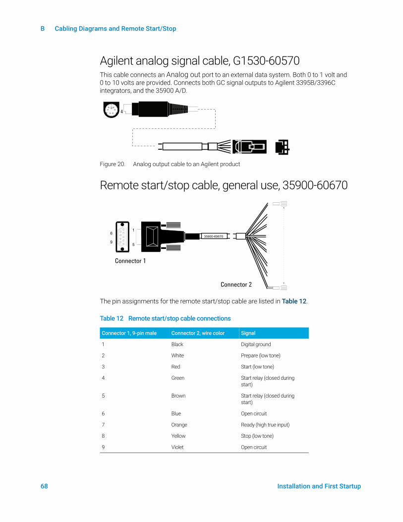
Agilent analog signal cable, G1530-60570This cable connects an Analog out port to an external data system. Both 0 to 1 volt and 0 to 10 volts are provided. Connects both GC signal outputs to Agilent 3395B/3396C integrators, and the 35900 A/D.
Figure 20. Analog output cable to an Agilent product
Remote start/stop cable, general use, 35900-60670
The pin assignments for the remote start/stop cable are listed in Table 12.
Table 12 Remote start/stop cable connections
Connector 1, 9-pin male Connector 2, wire color Signal
1 Black Digital ground
2 White Prepare (low tone)
3 Red Start (low tone)
4 Green Start relay (closed during start)
5 Brown Start relay (closed during start)
6 Blue Open circuit
7 Orange Ready (high true input)
8 Yellow Stop (low tone)
9 Violet Open circuit
4
35900-60670
16
59
Connector 1
Connector 2
B Cabling Diagrams and Remote Start/Stop
Installation and First Startup 69
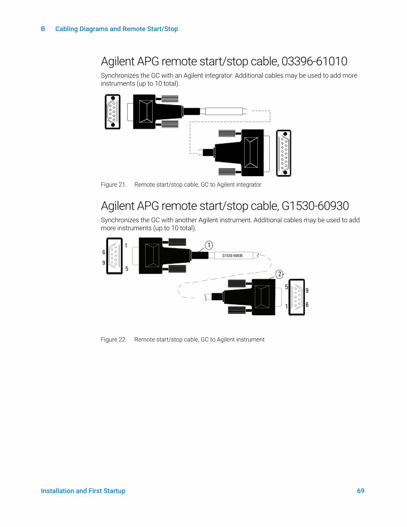
Agilent APG remote start/stop cable, 03396-61010Synchronizes the GC with an Agilent integrator. Additional cables may be used to add more instruments (up to 10 total).
Figure 21. Remote start/stop cable, GC to Agilent integrator
Agilent APG remote start/stop cable, G1530-60930Synchronizes the GC with another Agilent instrument. Additional cables may be used to add more instruments (up to 10 total).
Figure 22. Remote start/stop cable, GC to Agilent instrument
6
9
1
5
5
1
9
6
G1530-60930
9
6
5
1
1
2
B Cabling Diagrams and Remote Start/Stop
70 Installation and First Startup
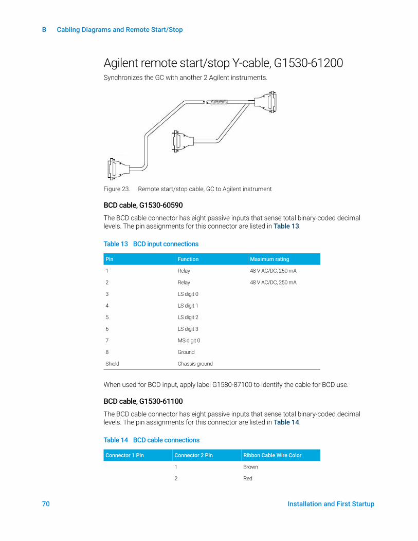
Agilent remote start/stop Y-cable, G1530-61200Synchronizes the GC with another 2 Agilent instruments.
Figure 23. Remote start/stop cable, GC to Agilent instrument
BCD cable, G1530-60590
The BCD cable connector has eight passive inputs that sense total binary-coded decimal levels. The pin assignments for this connector are listed in Table 13.
When used for BCD input, apply label G1580-87100 to identify the cable for BCD use.
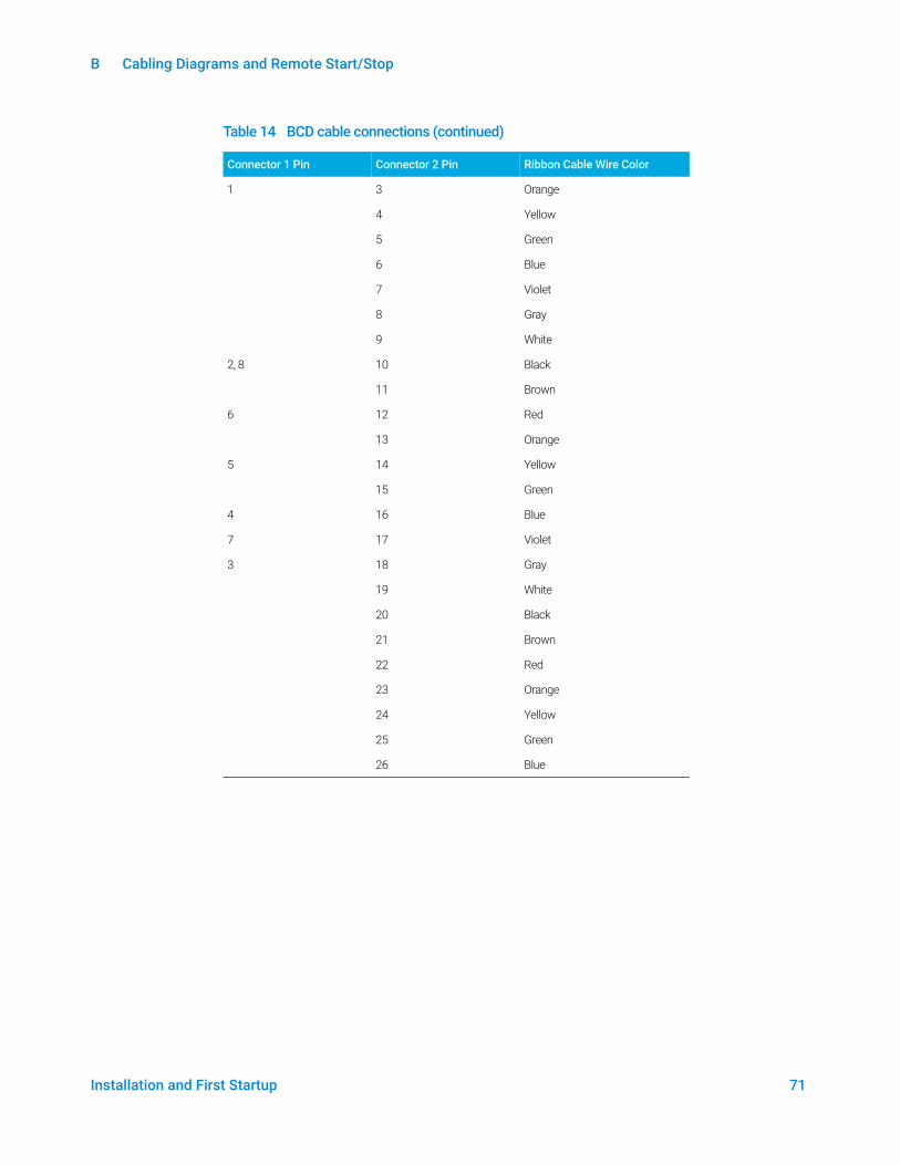
BCD cable, G1530-61100
The BCD cable connector has eight passive inputs that sense total binary-coded decimal levels. The pin assignments for this connector are listed in Table 14.
Table 13 BCD input connections
Pin Function Maximum rating
1 Relay 48 V AC/DC, 250 mA
2 Relay 48 V AC/DC, 250 mA
3 LS digit 0
4 LS digit 1
5 LS digit 2
6 LS digit 3
7 MS digit 0
8 Ground
Shield Chassis ground
Table 14 BCD cable connections
Connector 1 Pin Connector 2 Pin Ribbon Cable Wire Color
1 Brown
2 Red
B Cabling Diagrams and Remote Start/Stop
Installation and First Startup 71
1 3 Orange
4 Yellow
5 Green
6 Blue
7 Violet
8 Gray
9 White
2, 8 10 Black
11 Brown
6 12 Red
13 Orange
5 14 Yellow
15 Green
4 16 Blue
7 17 Violet
3 18 Gray
19 White
20 Black
21 Brown
22 Red
23 Orange
24 Yellow
25 Green
26 Blue
Table 14 BCD cable connections (continued)
Connector 1 Pin Connector 2 Pin Ribbon Cable Wire Color
B Cabling Diagrams and Remote Start/Stop
72 Installation and First Startup
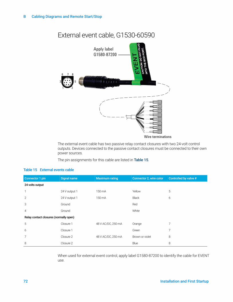
External event cable, G1530-60590
The external event cable has two passive relay contact closures with two 24-volt control outputs. Devices connected to the passive contact closures must be connected to their own power sources.
The pin assignments for this cable are listed in Table 15.
When used for external event control, apply label G1580-87200 to identify the cable for EVENT use.
4 5
6
3
1 2
7 8
Wire terminations
Apply label G1580-87200
Table 15 External events cable
Connector 1 pin Signal name Maximum rating Connector 2, wire color Controlled by valve #
24 volts output
1 24 V output 1 150 mA Yellow 5
2 24 V output 1 150 mA Black 6
3 Ground Red
4 Ground White
Relay contact closures (normally open)
5 Closure 1 48 V AC/DC, 250 mA Orange 7
6 Closure 1 Green 7
7 Closure 2 48 V AC/DC, 250 mA Brown or violet 8
8 Closure 2 Blue 8
B Cabling Diagrams and Remote Start/Stop
Installation and First Startup 73
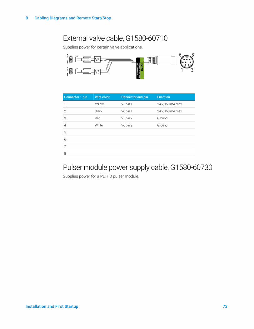
External valve cable, G1580-60710Supplies power for certain valve applications.
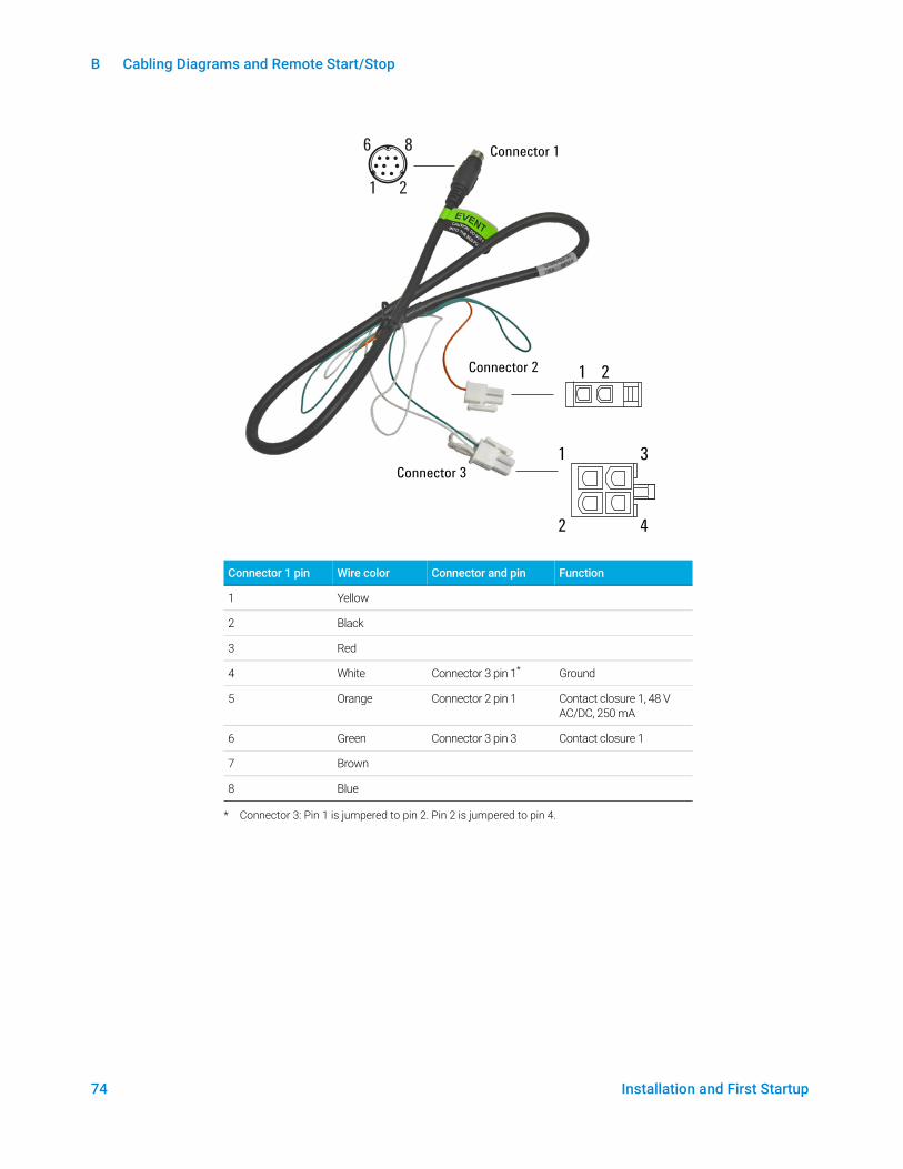
Pulser module power supply cable, G1580-60730Supplies power for a PDHID pulser module.
Connector 1 pin Wire color Connector and pin Function
1 Yellow V5 pin 1 24 V, 150 mA max.
2 Black V6 pin 1 24 V, 150 mA max.
3 Red V5 pin 2 Ground
4 White V6 pin 2 Ground
5
6
7
8
2
8
1
6
21
21 E
VEN
TC
AU
TIO
N: D
O N
OT P
LU
G
INTO
TH
E B
CD
PO
RT.
V5
V6
B Cabling Diagrams and Remote Start/Stop
74 Installation and First Startup
Connector 1 pin Wire color Connector and pin Function
1 Yellow
2 Black
3 Red
4 White Connector 3 pin 1*
* Connector 3: Pin 1 is jumpered to pin 2. Pin 2 is jumpered to pin 4.
Ground
5 Orange Connector 2 pin 1 Contact closure 1, 48 V AC/DC, 250 mA
6 Green Connector 3 pin 3 Contact closure 1
7 Brown
8 Blue
2
8
1
6
1
2
3
4
1 2
Connector 1
Connector 2
Connector 3

75 Installation and First Startup
This page intentionally left blank.

www.agilent.comAgilent Technologies, Inc. 2018
First edition, December 2018
*G2790-90013*G2790-90013