Embed Size (px)
Citation preview

Agilent Technologies 16557D
State/Timing Logic Analyzer
Programmer’s Guide
Insert this package in the back of either Programmer’s Guide binder includedwith the Agilent Technologies 16500 Logic Analysis System
Programmer’s Guide.


Programmer’s Guide
Publication number 16557-97005Second edition, January 2000
For Safety information, Warranties, and Regulatory
information, see the pages behind the Index
Copyright Agilent Technologies 1987-2000 All Rights Reserved
Agilent Technologies 16557DState/Timing Logic Analyzer

ii
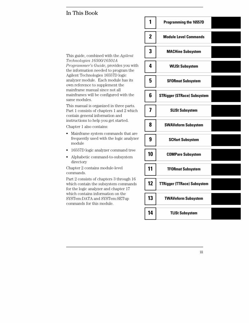
In This Book
This guide, combined with the Agilent
Technologies 16500/16501A
Programmer’s Guide, provides you withthe information needed to program theAgilent Technologies 16557D logicanalyzer module. Each module has itsown reference to supplement themainframe manual since not allmainframes will be configured with thesame modules.
This manual is organized in three parts.Part 1 consists of chapters 1 and 2 whichcontain general information andinstructions to help you get started.
Chapter 1 also contains:
• Mainframe system commands that arefrequently used with the logic analyzermodule
• 16557D logic analyzer command tree
• Alphabetic command-to-subsystemdirectory
Chapter 2 contains module-levelcommands.
Part 2 consists of chapters 3 through 16which contain the subsystem commandsfor the logic analyzer and chapter 17which contains information on theSYSTem:DATA and SYSTem:SETupcommands for this module.
Programming the 16557D1
Module Level Commands2
MACHine Subsystem3
WLISt Subsystem4
SFORmat Subsystem5
STRigger (STRace) Subsystem6
SLISt Subsystem7
SWAVeform Subsystem8
SCHart Subsystem9
COMPare Subsystem10
TFORmat Subsystem11
TTRigger (TTRace) Subsystem12
TWAVeform Subsystem13
TLISt Subsystem14
iii

Part 3, chapter 18, contains program examples of actual tasks that show youhow to get started in programming the 16557D logic analyzer. Theseexamples are written in HP BASIC 6.2; however, the program concepts canbe used in any other popular programming language.
Error messages for the 16557D are included in generic system errormessages and are in the Agilent Technologies 16500/16501A
Programmer’s Guide.
iv
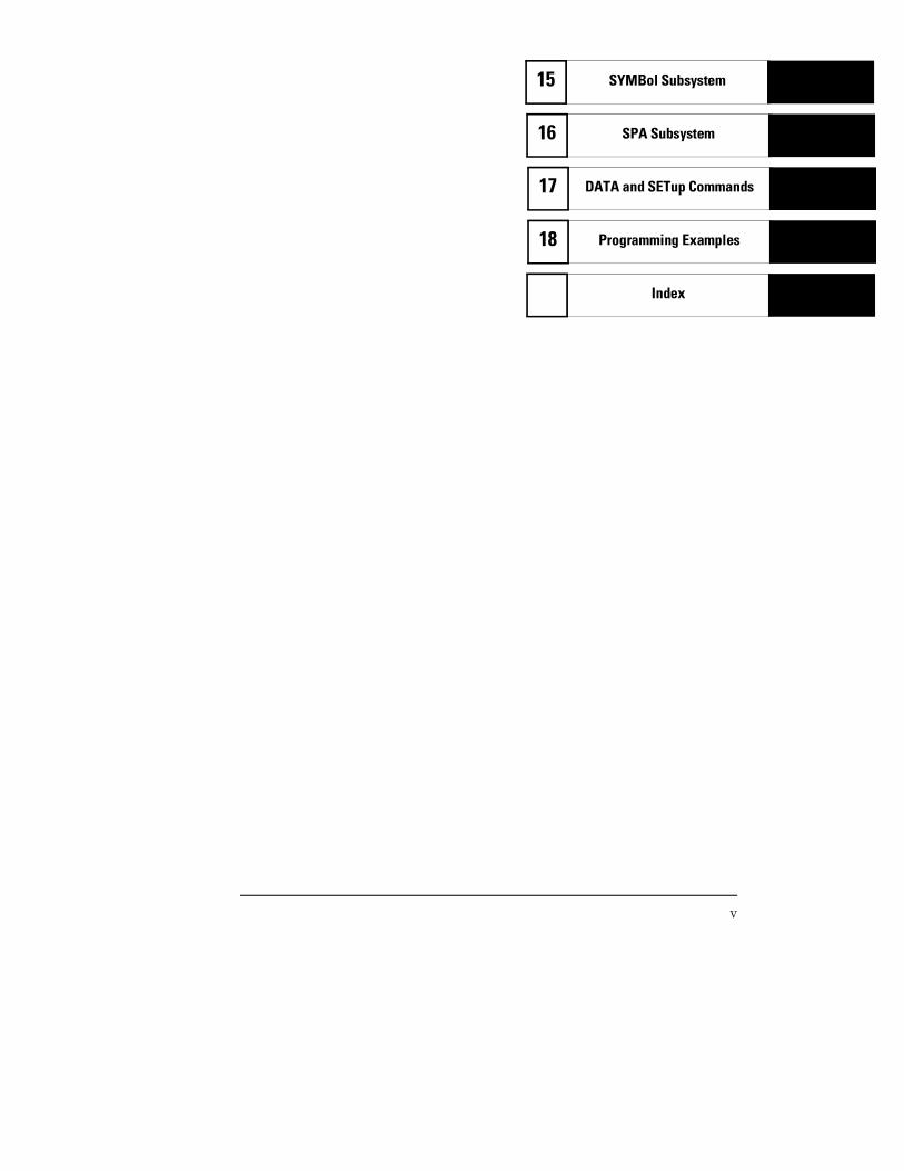
SPA Subsystem16
DATA and SETup Commands17
Programming Examples18
Index
SYMBol Subsystem15
v

vi
Contents
Part 1 General Information
1 Programming the 16557D
Selecting the Module 1–3Programming the Logic Analyzer 1–3Mainframe Commands 1–5Command Set Organization 1–8Module Status Reporting 1–12MESE<N> 1–13MESR<N> 1–15
2 Module Level Commands
ARMLine 2–5DBLock 2–5MACHine 2–6SPA 2–7WLISt 2–7
Part 2 Commands
3 MACHine Subsystem
MACHine 3–4ARM 3–5ASSign 3–6LEVelarm 3–7NAME 3–8REName 3–8RESource 3–9TYPE 3–10
4 WLISt Subsystem
WLISt 4–4DELay 4–5INSert 4–6
Contents–1
LINE 4–7MINus 4–8OSTate 4–9OTIMe 4–9OVERlay 4–10PLUS 4–11RANGe 4–12REMove 4–12XOTime 4–13XSTate 4–13XTIMe 4–14
5 SFORmat Subsystem
SFORmat 5–6CLOCk 5–6LABel 5–7MASTer 5–9MOPQual 5–10MQUal 5–11REMove 5–12SETHold 5–12SLAVe 5–14SOPQual 5–15SQUal 5–16THReshold 5–17
6 STRigger (STRace) Subsystem
Qualifier 6–6STRigger (STRace) 6–8ACQuisition 6–8BRANch 6–9CLEar 6–11FIND 6–12MLENgth 6–13RANGe 6–14SEQuence 6–15
Contents
Contents–2
STORe 6–16TAG 6–17TAKenbranch 6–18TCONtrol 6–19TERM 6–20TIMER 6–21TPOSition 6–22
7 SLISt Subsystem
SLISt 7–7COLumn 7–7CLRPattern 7–8DATA 7–9LINE 7–9MMODe 7–10OPATtern 7–11OSEarch 7–12OSTate 7–13OTAG 7–14OVERlay 7–15REMove 7–15RUNTil 7–16TAVerage 7–17TMAXimum 7–17TMINimum 7–18VRUNs 7–18XOTag 7–19XOTime 7–19XPATtern 7–20XSEarch 7–21XSTate 7–22XTAG 7–22
8 SWAVeform Subsystem
SWAVeform 8–4ACCumulate 8–5
Contents
Contents–3
ACQuisition 8–5CENTer 8–6CLRPattern 8–6CLRStat 8–7DELay 8–7INSert 8–8MLENgth 8–8RANGe 8–9REMove 8–10TAKenbranch 8–10TPOSition 8–11
9 SCHart Subsystem
SCHart 9–4ACCumulate 9–4CENTer 9–5HAXis 9–5VAXis 9–6
10 COMPare Subsystem
COMPare 10–4CLEar 10–5CMASk 10–5COPY 10–6DATA 10–6FIND 10–8LINE 10–9MENU 10–9RANGe 10–10RUNTil 10–11SET 10–12
11 TFORmat Subsystem
TFORmat 11–4ACQMode 11–5
Contents
Contents–4
LABel 11–6REMove 11–7THReshold 11–8
12 TTRigger (TTRace) Subsystem
Qualifier 12–6TTRigger (TTRace) 12–8ACQuisition 12–9BRANch 12–9CLEar 12–12EDGE 12–13FIND 12–14MLENgth 12–16RANGe 12–17SEQuence 12–18SPERiod 12–19TCONtrol 12–20TERM 12–21TIMER 12–22TPOSition 12–23
13 TWAVeform Subsystem
TWAVeform 13–7ACCumulate 13–7ACQuisition 13–8CENTer 13–9CLRPattern 13–9CLRStat 13–9DELay 13–10INSert 13–11MLENgth 13–12MINus 13–13MMODe 13–14OCONdition 13–15OPATtern 13–16OSEarch 13–17
Contents
Contents–5
OTIMe 13–18OVERlay 13–18PLUS 13–19RANGe 13–20REMove 13–20RUNTil 13–21SPERiod 13–22TAVerage 13–23TMAXimum 13–23TMINimum 13–24TPOSition 13–24VRUNs 13–25XCONdition 13–26XOTime 13–26XPATtern 13–27XSEarch 13–28XTIMe 13–29
14 TLISt Subsystem
TLISt 14–7COLumn 14–7CLRPattern 14–8DATA 14–9LINE 14–9MMODe 14–10OCONdition 14–11OPATtern 14–12OSEarch 14–13OSTate 14–14OTAG 14–14REMove 14–15RUNTil 14–16TAVerage 14–17TMAXimum 14–17TMINimum 14–18VRUNs 14–18
Contents
Contents–6
XCONdition 14–19XOTag 14–19XOTime 14–20XPATtern 14–20XSEarch 14–21XSTate 14–22XTAG 14–23
15 SYMBol Subsystem
SYMBol 15–5BASE 15–5PATTern 15–6RANGe 15–7REMove 15–8WIDTh 15–8
16 SPA Subsystem
MODE 16–7OVERView:BUCKet 16–8OVERView:HIGH 16–9OVERView:LABel 16–10OVERView:LOW 16–11OVERView:MLENgth 16–12OVERView:OMARker 16–13OVERView:OVSTatistic 16–14OVERView:XMARker 16–15HISTogram:HSTatistic 16–16HISTogram:LABel 16–17HISTogram:OTHer 16–18HISTogram:QUALifier 16–19HISTogram:RANGe 16–20HISTogram:TTYPe 16–21TINTerval:AUTorange 16–22TINTerval:QUALifier 16–23TINTerval:TINTerval 16–24TINTerval:TSTatistic 16–25
Contents
Contents–7
17 DATA and SETup Commands
Introduction 17–2
Data Format 17–3SYSTem:DATA 17–4Section Header Description 17–6Section Data 17–6Data Preamble Description 17–7Acquisition Data Description 17–12Time Tag Data Description 17–14SYSTem:SETup 17–14
Part 3 Programming Examples
18 Programming Examples
Making a Timing Analyzer Measurement 18–3Making a State Analyzer Measurement 18–5Making a State Compare Analyzer Measurement 18–9Transferring the Logic Analyzer Configuration 18–14Checking for Measurement Completion 18–18Sending Queries to the Logic Analyzer 18–19
Contents
Contents–8

Part 1
1 Introduction to Programming2 Module Level Commands
General Information

1
Programming the 16557D
Introduction
This chapter introduces you to the basic command structure used toprogram the logic analyzer. Also included is an example program thatsets up the timing analyzer for a basic timing measurement.Additional program examples are in chapter 18.
1–2
Selecting the Module
Before you can program the logic analyzer, you must first "select" it. Thisdirects your commands to the logic analyzer.
To select the module, use the system command :SELect followed by thenumeric reference for the slot location of the logic analyzer (1 through 10referring to slots A through J respectively). For example, if the logic analyzeris in slot E, then the command:
:SELect 5
would select this module. For more information on the select command,refer to the Agilent Technologies 16500/16501A Programmer’s Guide. Itis available through your Agilent Technologies Sales Office.
Programming the Logic Analyzer
A typical logic analyzer program will do the following:
• select the appropriate module
• name a specified analyzer
• specify the analyzer type
• assign pods
• assign labels
• sets pod thresholds
• specify a trigger condition
• set up the display
• specify acquisition type
• start acquiring data
Programming the 16557DSelecting the Module
1–3
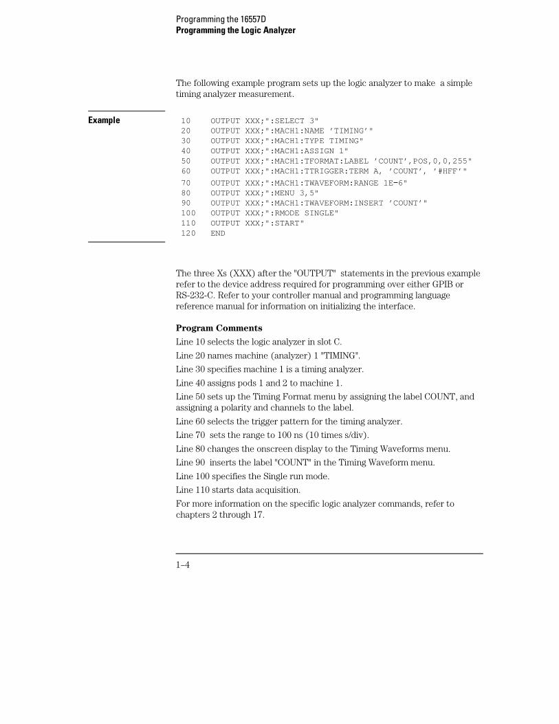
The following example program sets up the logic analyzer to make a simpletiming analyzer measurement.
Example 10 OUTPUT XXX;":SELECT 3" 20 OUTPUT XXX;":MACH1:NAME ’TIMING’" 30 OUTPUT XXX;":MACH1:TYPE TIMING" 40 OUTPUT XXX;":MACH1:ASSIGN 1" 50 OUTPUT XXX;":MACH1:TFORMAT:LABEL ’COUNT’,POS,0,0,255" 60 OUTPUT XXX;":MACH1:TTRIGGER:TERM A, ’COUNT’, ’#HFF’"
70 OUTPUT XXX;":MACH1:TWAVEFORM:RANGE 1E −6" 80 OUTPUT XXX;":MENU 3,5" 90 OUTPUT XXX;":MACH1:TWAVEFORM:INSERT ’COUNT’" 100 OUTPUT XXX;":RMODE SINGLE" 110 OUTPUT XXX;":START" 120 END
The three Xs (XXX) after the "OUTPUT" statements in the previous examplerefer to the device address required for programming over either GPIB orRS-232-C. Refer to your controller manual and programming languagereference manual for information on initializing the interface.
Program Comments
Line 10 selects the logic analyzer in slot C.
Line 20 names machine (analyzer) 1 "TIMING".
Line 30 specifies machine 1 is a timing analyzer.
Line 40 assigns pods 1 and 2 to machine 1.
Line 50 sets up the Timing Format menu by assigning the label COUNT, andassigning a polarity and channels to the label.
Line 60 selects the trigger pattern for the timing analyzer.
Line 70 sets the range to 100 ns (10 times s/div).
Line 80 changes the onscreen display to the Timing Waveforms menu.
Line 90 inserts the label "COUNT" in the Timing Waveform menu.
Line 100 specifies the Single run mode.
Line 110 starts data acquisition.
For more information on the specific logic analyzer commands, refer tochapters 2 through 17.
Programming the 16557DProgramming the Logic Analyzer
1–4
Mainframe Commands
These commands are part of the Agilent Technologies 16500/16501Amainframe system and are mentioned here only for reference. For moreinformation on these commands, refer to the Agilent Technologies
16500/16501A Programmer’s Guide.
CARDcage? Query
The CARDcage query returns a string of integers which identifies themodules that are installed in the mainframe. The returned string is in twoparts. The first five two-digit numbers identify the card type. Theidentification number for the 16557D logic analyzer is 34. A "−1" in the firstpart of the string indicates no card is installed in the slot.
The five single-digit numbers in the second part of the string indicate whichcard has the controlling software for the module; that is, where the mastercard is located.
Example 12,11, −1, −1,34,2,2,0,0,5
A returned string of 12,11,-1,-1,34,2,2,0,0,5 means that anoscilloscope time base card (ID number 11) is loaded in slot B and theoscilloscope acquisition card (ID number 12) is loaded in slot A. The nexttwo slots (C and D) are empty (−1). Slot E contains a logic analyzer module(ID number 34).
The next group of numbers (2,2,0,0,5 ) indicate that a two-card module isinstalled in slots A and B with the master card in slot B. The "0" indicates anempty slot, or the module software is not recognized or is not loaded. Thelast digit (5) in this group indicates a one-card module is loaded in slot E.Complete information for the CARDcage query is in the Agilent
Technologies 16500/16501A Programmer’s Guide.
Programming the 16557DMainframe Commands
1–5
MENU Command/query
The MENU command selects a new displayed menu. The first parameter (X)specifies the desired module. The optional, second parameter specifies thedesired menu in the module. The second parameter defaults to 0 if it is notspecified. The query returns the currently selected and displayed menu.
For the 16557D Logic Analyzer:
If a machine is turned off, its menus are not available. The Mixed Display isavailable only when one or both analyzers are state analyzers.
SELect Command/query
The SELect command selects which module or intermodule will have parsercontrol. SELect 0 selects the intermodule, SELect 1 through 5 selectsmodules A through E respectively. Values −1 and −2 select software options1 and 2. The SELect query returns the currently selected module.
STARt Command
The STARt command starts the specified module. If the specified module isconfigured for intermodule (group run), STARt will start all modulesconfigured as part of the intermodule run.
• X,0 — State/TimingConfiguration
• X,1 — Format 1
• X,2 — Format 2
• X,3 — Trigger 1
• X,4 — Trigger 2
• X,5 — Waveform 1
• X,6 — Waveform 2
• X,7 — Listing 1
• X,8 — Listing 2
• X,9 — Mixed Display
• X,10 — Compare 1
• X,11 — Compare 2
• X,12 — Chart 1
• X,13 — Chart 2
• X,14 — SPA 1
• X,15 — SPA 2
Programming the 16557DMainframe Commands
1–6
STOP Command
The STOP command stops the specified module. If the specified module isconfigured as part of an intermodule run, STOP will stop all associatedmodules.
STARt and STOP are overlapped commands. Overlapped commands allowexecution of subsequent commands while the logic analyzer operationsinitiated by the overlapped command are still in progress. For moreinformation, see *OPC and *WAI commands in Chapter 5 of the Agilent
Technologies 16500/16501A Programmer’s Guide.
RMODe Command/query
The RMODe command specifies the run mode (single or repetitive) for amodule. If the selected module is configured for intermodule, theintermodule run mode will be set by this command. The RMODe queryreturns the current setting.
SYSTem:ERRor? Query
The SYSTem:ERRor query returns the oldest error in the error queue. Inorder to return all the errors in the error queue, a simple FOR/NEXT loop canbe written to query the queue until all errors are returned. Once all errorsare returned, the query will return zeros.
SYSTem:PRINt Command/query
The SYSTem:PRINt command initiates a print of the screen or listing bufferover the current printer communication interface. The SYSTem:PRINt querysends the screen or listing buffer data over the current controllercommunication interface.
MMEMory Subsystem
The MMEMory Subsystem provides access to both internal disc drives forloading and storing configurations.
INTermodule Subsystem
The INTermodule Subsystem commands are used to specify intermodulearming between multiple modules.
Programming the 16557DMainframe Commands
1–7
Command Set Organization
The command set for the 16557D is divided into module-level commands andsubsystem commands. Module-level commands are listed in Chapter 2,"Module Level Commands" and each of the subsystem commands are coveredin their individual chapters starting with Chapter 3, "MACHine Subsystem."
Each of these chapters contains a description of the subsystem, syntaxdiagrams, and the commands in alphabetical order. The commands areshown in long form and short form using upper and lowercase letters. Forexample, LABel indicates that the long form of the command is LABEL andthe short form is LAB. Each of the commands contain a description of thecommand and its arguments, the command syntax, and a programmingexample.
Figure 1-1 on the following page shows the command tree for the 16557Dlogic analyzer module. The (x) following the SELect command at the top ofthe tree represents the slot number where the logic analyzer module isinstalled. The number may range from 1 through 10, representing slots Athrough J, respectively.
Programming the 16557DCommand Set Organization
1–8

16557D Command Tree
Figure 1-1
Programming the 16557DCommand Set Organization
1–9
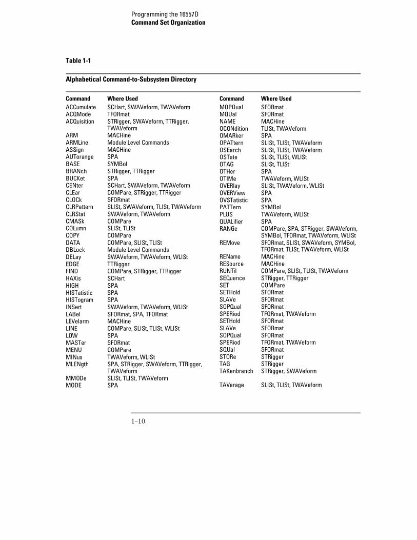
Table 1-1
Alphabetical Command-to-Subsystem Directory
Command Where UsedACCumulate SCHart, SWAVeform, TWAVeformACQMode TFORmatACQuisition STRigger, SWAVeform, TTRigger,
TWAVeformARM MACHineARMLine Module Level CommandsASSign MACHineAUTorange SPABASE SYMBolBRANch STRigger, TTRiggerBUCKet SPACENter SCHart, SWAVeform, TWAVeformCLEar COMPare, STRigger, TTRiggerCLOCk SFORmatCLRPattern SLISt, SWAVeform, TLISt, TWAVeformCLRStat SWAVeform, TWAVeformCMASk COMPareCOLumn SLISt, TLIStCOPY COMPareDATA COMPare, SLISt, TLIStDBLock Module Level CommandsDELay SWAVeform, TWAVeform, WLIStEDGE TTRiggerFIND COMPare, STRigger, TTRiggerHAXis SCHartHIGH SPAHISTatistic SPAHISTogram SPAINSert SWAVeform, TWAVeform, WLIStLABel SFORmat, SPA, TFORmatLEVelarm MACHineLINE COMPare, SLISt, TLISt, WLIStLOW SPAMASTer SFORmatMENU COMPareMINus TWAVeform, WLIStMLENgth SPA, STRigger, SWAVeform, TTRigger,
TWAVeformMMODe SLISt, TLISt, TWAVeformMODE SPA
Command Where UsedMOPQual SFORmatMQUal SFORmatNAME MACHineOCONdition TLISt, TWAVeformOMARker SPAOPATtern SLISt, TLISt, TWAVeformOSEarch SLISt, TLISt, TWAVeformOSTate SLISt, TLISt, WLIStOTAG SLISt, TLIStOTHer SPAOTIMe TWAVeform, WLIStOVERlay SLISt, TWAVeform, WLIStOVERView SPAOVSTatistic SPAPATTern SYMBolPLUS TWAVeform, WLIStQUALifier SPARANGe COMPare, SPA, STRigger, SWAVeform,
SYMBol, TFORmat, TWAVeform, WLIStREMove SFORmat, SLISt, SWAVeform, SYMBol,
TFORmat, TLISt, TWAVeform, WLISt REName MACHineRESource MACHineRUNTil COMPare, SLISt, TLISt, TWAVeformSEQuence STRigger, TTRiggerSET COMPareSETHold SFORmatSLAVe SFORmatSOPQual SFORmatSPERiod TFORmat, TWAVeformSETHold SFORmatSLAVe SFORmatSOPQual SFORmatSPERiod TFORmat, TWAVeformSQUal SFORmatSTORe STRiggerTAG STRiggerTAKenbranch STRigger, SWAVeform
TAVerage SLISt, TLISt, TWAVeform
Programming the 16557DCommand Set Organization
1–10
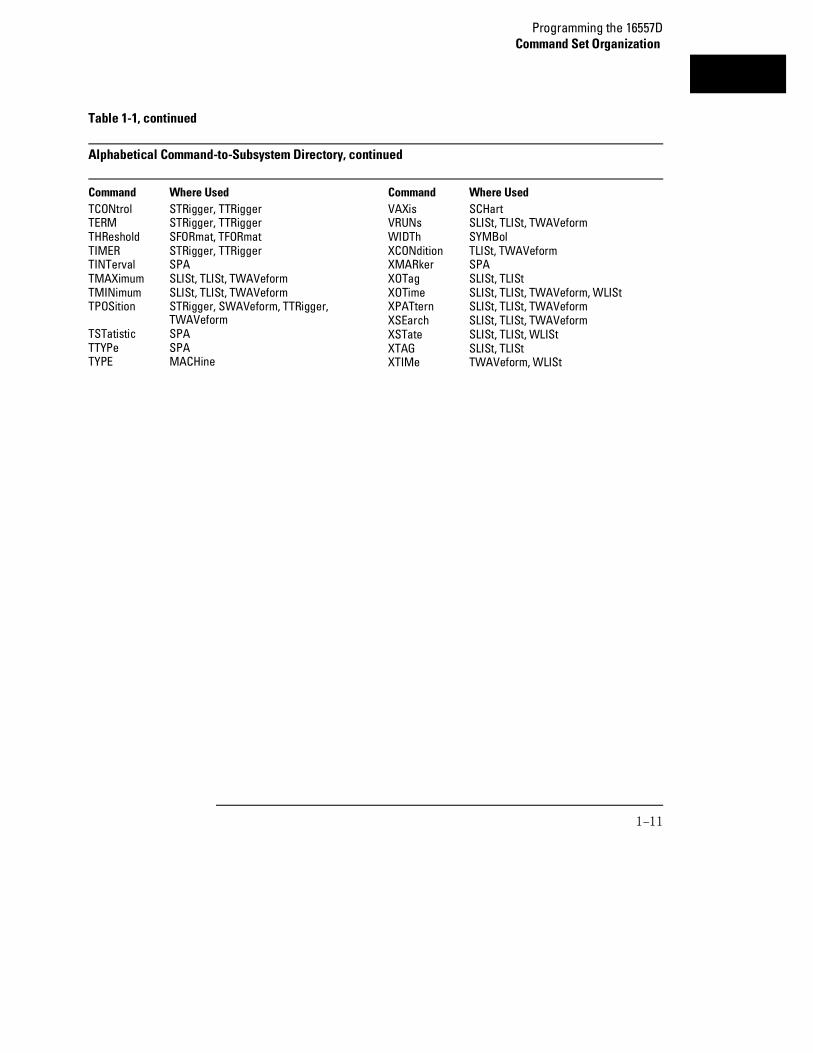
Table 1-1, continued
Alphabetical Command-to-Subsystem Directory, continued
Command Where UsedTCONtrol STRigger, TTRiggerTERM STRigger, TTRiggerTHReshold SFORmat, TFORmatTIMER STRigger, TTRiggerTINTerval SPATMAXimum SLISt, TLISt, TWAVeformTMINimum SLISt, TLISt, TWAVeformTPOSition STRigger, SWAVeform, TTRigger,
TWAVeformTSTatistic SPATTYPe SPATYPE MACHine
Command Where UsedVAXis SCHartVRUNs SLISt, TLISt, TWAVeformWIDTh SYMBolXCONdition TLISt, TWAVeformXMARker SPAXOTag SLISt, TLIStXOTime SLISt, TLISt, TWAVeform, WLIStXPATtern SLISt, TLISt, TWAVeformXSEarch SLISt, TLISt, TWAVeformXSTate SLISt, TLISt, WLIStXTAG SLISt, TLIStXTIMe TWAVeform, WLISt
Programming the 16557DCommand Set Organization
1–11
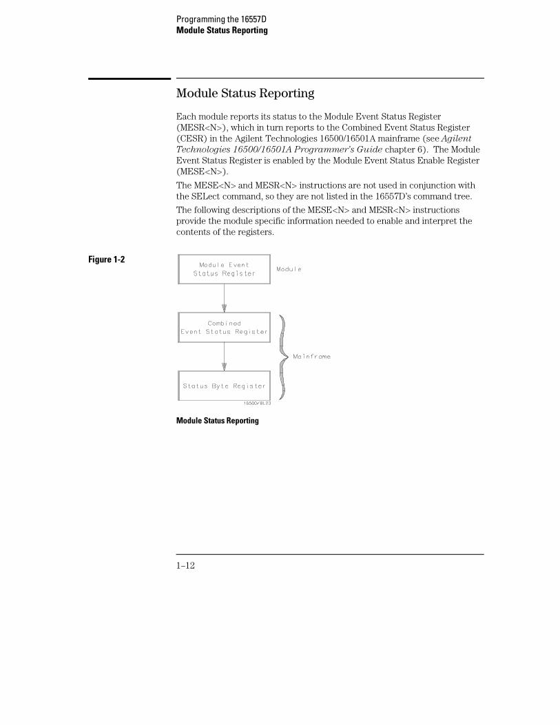
Module Status Reporting
Each module reports its status to the Module Event Status Register(MESR<N>), which in turn reports to the Combined Event Status Register(CESR) in the Agilent Technologies 16500/16501A mainframe (see Agilent
Technologies 16500/16501A Programmer’s Guide chapter 6). The ModuleEvent Status Register is enabled by the Module Event Status Enable Register(MESE<N>).
The MESE<N> and MESR<N> instructions are not used in conjunction withthe SELect command, so they are not listed in the 16557D’s command tree.
The following descriptions of the MESE<N> and MESR<N> instructionsprovide the module specific information needed to enable and interpret thecontents of the registers.
Figure 1-2
Module Status Reporting
Programming the 16557DModule Status Reporting
1–12
MESE<N>
Command :MESE<N> <enable_mask>
The MESE<N> command sets the Module Event Status Enable register bits.The MESE register contains a mask value for the bits enabled in the MESRregister. A one in the MESE will enable the corresponding bit in the MESR, azero will disable the bit.
The first parameter <N> specifies the module. The second parameterspecifies the enable value.
Refer to table 1-2 for information about the Module Event Status register bits,bit weights, and what each bit masks for the module. Complete informationfor status reporting is in chapter 6 of the Agilent Technologies
16500/16501A Programmer’s Guide manual.
<N> {1|2|3|4|5|6|7|8|9|10} number of slot in which the module resides. 1refers to slot A, and so on.
<enable_mask> integer from 0 to 255
Example OUTPUT XXX;":MESE5 1"
Query :MESE<N>?
The MESE query returns the current setting.Returned Format [:MESE<N>]<enable_mask><NL>
Example 10 OUTPUT XXX;":MESE5?" 20 ENTER XXX; Mes 30 PRINT Mes 40 END
Programming the 16557DMESE<N>
1–13
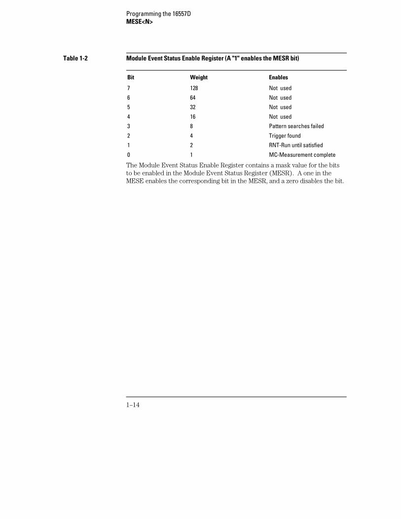
Table 1-2 Module Event Status Enable Register (A "1" enables the MESR bit)
Bit Weight Enables
7 128 Not used
6 64 Not used
5 32 Not used
4 16 Not used
3 8 Pattern searches failed
2 4 Trigger found
1 2 RNT-Run until satisfied
0 1 MC-Measurement complete
The Module Event Status Enable Register contains a mask value for the bitsto be enabled in the Module Event Status Register (MESR). A one in theMESE enables the corresponding bit in the MESR, and a zero disables the bit.
Programming the 16557DMESE<N>
1–14
MESR<N>
Query :MESR<N>?
The MESR<N> query returns the contents of the Module Event Statusregister. When you read the MESR, the value returned is the total bit weightsof all bits that are set at the time the register is read. Reading the registerclears the Module Event Status Register.
Table 1-3 shows each bit in the Module Event Status Register and its bitweight for this module.
The parameter 1 through 10 refers to the module in slot A through Jrespectively.
Returned Format [MESR<N>]<status><NL>
<N> {1|2|3|4|5|6|7|8|9|10} number of slot in which the module resides
<status> integer from 0 to 255
Example 10 OUTPUT XXX;":MESR5?" 20 ENTER XXX; Mer 30 PRINT Mer 40 END
Programming the 16557DMESR<N>
1–15
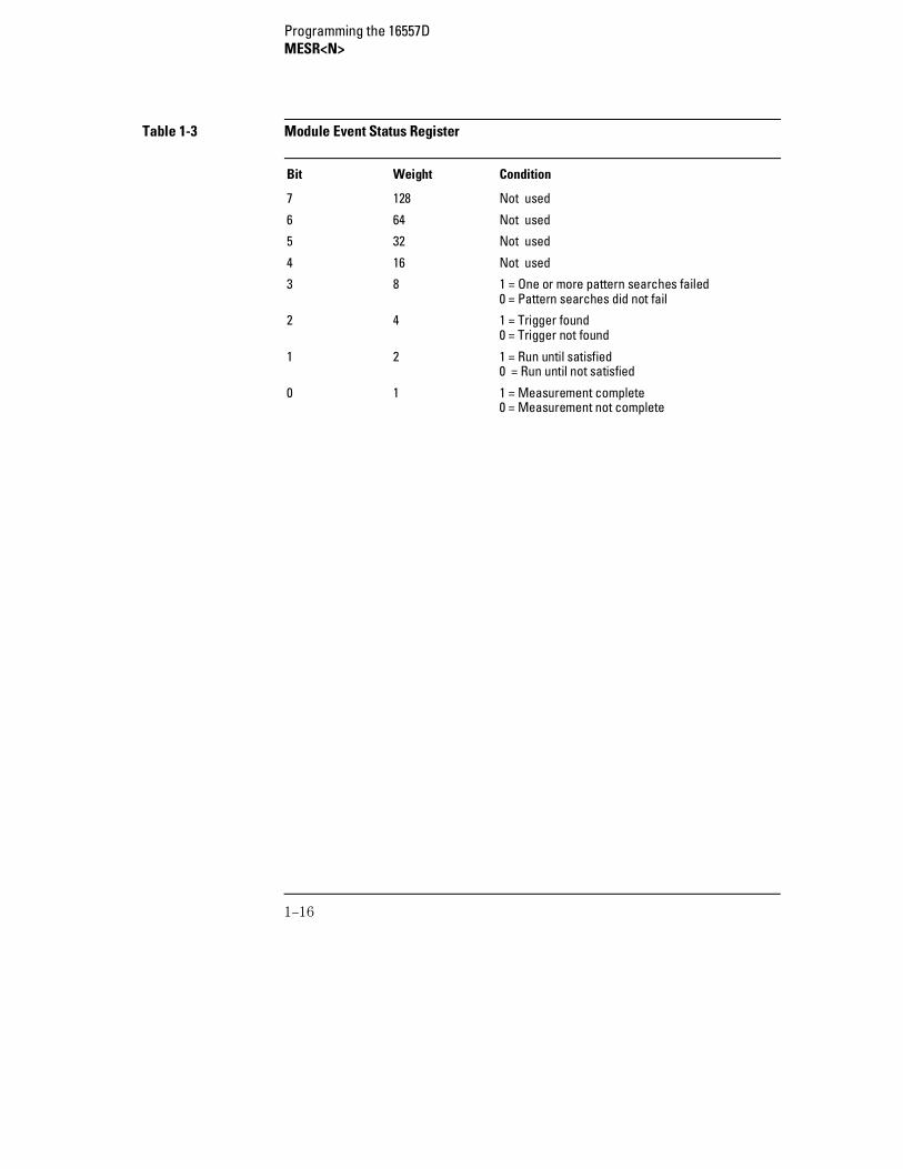
Table 1-3 Module Event Status Register
Bit Weight Condition
7 128 Not used
6 64 Not used
5 32 Not used
4 16 Not used
3 8 1 = One or more pattern searches failed0 = Pattern searches did not fail
2 4 1 = Trigger found0 = Trigger not found
1 2 1 = Run until satisfied0 = Run until not satisfied
0 1 1 = Measurement complete0 = Measurement not complete
Programming the 16557DMESR<N>
1–16
2
Module Level Commands
Introduction
The logic analyzer module level commands access the globalfunctions of the 16557D logic analyzer module. These commands are:
• ARMLine
• DBLock
• MACHine
• SPA
• WLISt
2–2
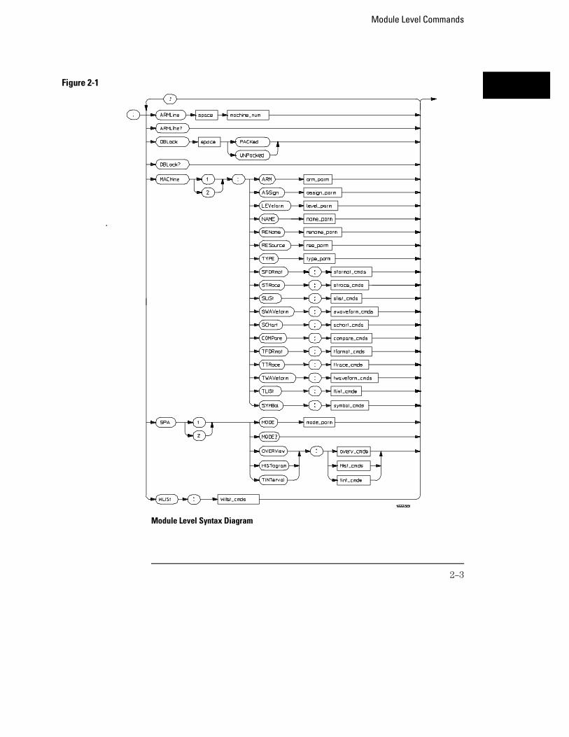
Module Level Syntax Diagram
Figure 2-1
Module Level Commands
2–3
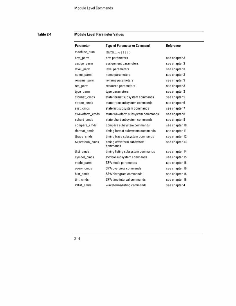
Table 2-1 Module Level Parameter Values
Parameter Type of Parameter or Command Reference
machine_num MACHine{1|2}
arm_parm arm parameters see chapter 3
assign_parm assignment parameters see chapter 3
level_parm level parameters see chapter 3
name_parm name parameters see chapter 3
rename_parm rename parameters see chapter 3
res_parm resource parameters see chapter 3
type_parm type parameters see chapter 3
sformat_cmds state format subsystem commands see chapter 5
strace_cmds state trace subsystem commands see chapter 6
slist_cmds state list subsystem commands see chapter 7
swaveform_cmds state waveform subsystem commands see chapter 8
schart_cmds state chart subsystem commands see chapter 9
compare_cmds compare subsystem commands see chapter 10
tformat_cmds timing format subsystem commands see chapter 11
ttrace_cmds timing trace subsystem commands see chapter 12
twaveform_cmds timing waveform subsystemcommands
see chapter 13
tlist_cmds timing listing subsystem commands see chapter 14
symbol_cmds symbol subsystem commands see chapter 15
mode_parm SPA mode parameters see chapter 16
overv_cmds SPA overview commands see chapter 16
hist_cmds SPA histogram commands see chapter 16
tint_cmds SPA time interval commands see chapter 16
Wlist_cmds waveforms/listing commands see chapter 4
Module Level Commands
2–4
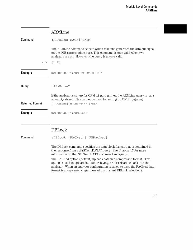
ARMLine
Command :ARMLine MACHine<N>
The ARMLine command selects which machine generates the arm out signalon the IMB (intermodule bus). This command is only valid when twoanalyzers are on. However, the query is always valid.
<N> {1|2}
Example OUTPUT XXX;":ARMLINE MACHINE1"
Query :ARMLine?
If the analyzer is set up for OR’d triggering, then the ARMLine query returnsan empty string. This cannot be used for setting up OR’d triggering.
Returned Format [:ARMLine]{MACHine<N>|}<NL>
Example OUTPUT XXX;":ARMLine?"
DBLock
Command :DBLock {PACKed | UNPacked}
The DBLock command specifies the data block format that is contained inthe response from a :SYSTem:DATA? query. See Chapter 17 for moreinformation on the :SYSTem:DATA command and query.
The PACKed option (default) uploads data in a compressed format. Thisoption is used to upload data for archiving, or for reloading back into theanalyzer. When an analyzer configuration is saved to disk, the PACKed dataformat is always used (regardless of the current DBLock selection).
Module Level CommandsARMLine
2–5
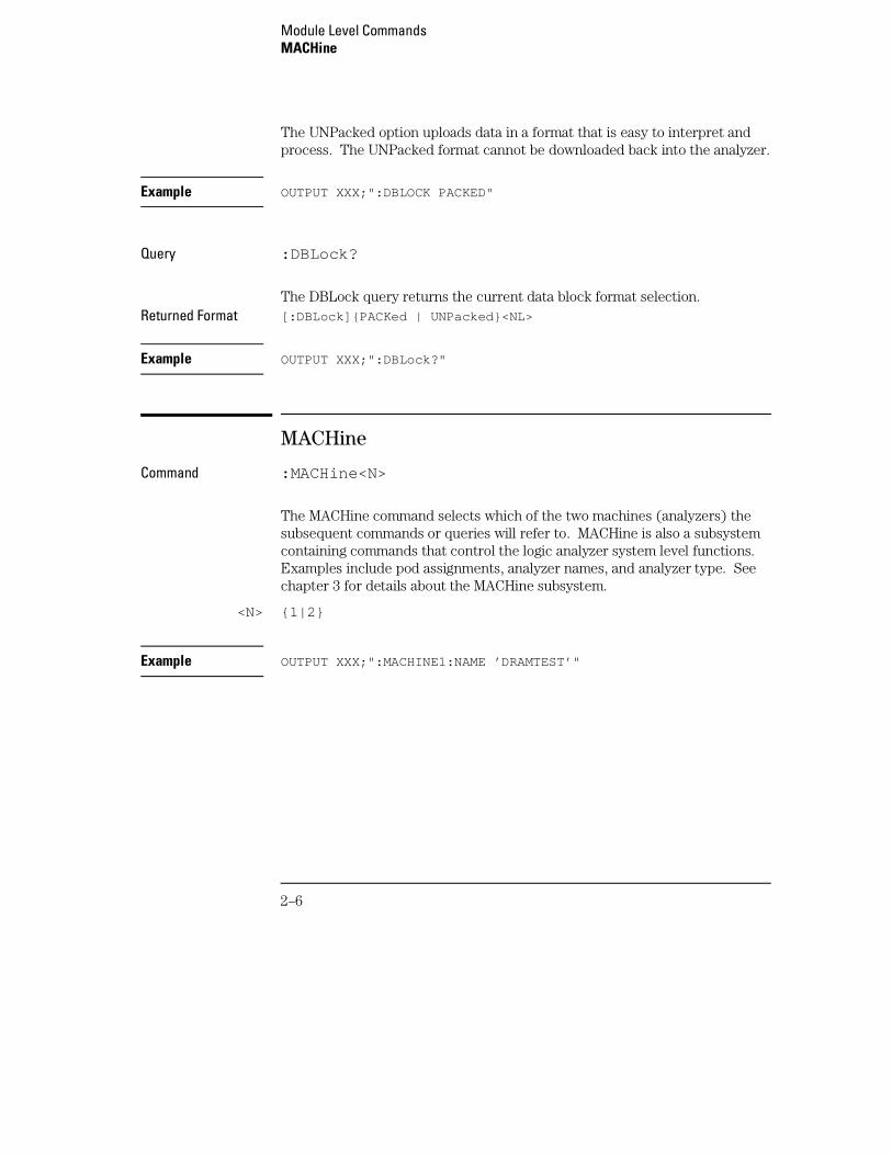
The UNPacked option uploads data in a format that is easy to interpret andprocess. The UNPacked format cannot be downloaded back into the analyzer.
Example OUTPUT XXX;":DBLOCK PACKED"
Query :DBLock?
The DBLock query returns the current data block format selection.Returned Format [:DBLock]{PACKed | UNPacked}<NL>
Example OUTPUT XXX;":DBLock?"
MACHine
Command :MACHine<N>
The MACHine command selects which of the two machines (analyzers) thesubsequent commands or queries will refer to. MACHine is also a subsystemcontaining commands that control the logic analyzer system level functions.Examples include pod assignments, analyzer names, and analyzer type. Seechapter 3 for details about the MACHine subsystem.
<N> {1|2}
Example OUTPUT XXX;":MACHINE1:NAME ’DRAMTEST’"
Module Level CommandsMACHine
2–6
SPA
Command :SPA<N>
The SPA command selects which of the two analyzers the subsequentcommands or queries will refer to. SPA is also a subsystem containingcommands that control the logic analyzer SPA functions. See chapter 16 fordetails about the SPA subsystem.
<N> {1|2}
Example OUTPUT XXX;":SPA1:MODE OVERVIEW"
WLISt
Command :WLISt
The WLISt selector accesses the commands used to place markers and querymarker positions in Timing/State Mixed mode. The WLISt subsystem alsocontains commands that allows you to insert waveforms from othertime-correlated machines and modules. The details of the WLISt subsystemare in chapter 4.
Example OUTPUT XXX;":WLIST:OTIME 40.0E −6"
Module Level CommandsSPA
2–7

2–8
Part 2
3 MACHine Subsystem4 WLISt Subsystem5 SFORmat Subsystem6 STRigger (STRace) Subsystem7 SLISt Subsystem8 SWAVeform Subsystem9 SCHart Subsystem
10 COMPare Subsystem11 TFORmat Subsystem12 TTRigger (TTRace) Subsystem13 TWAVeform Subsystem14 TLISt Subsystem15 SYMBol Subsystem16 SPA Subsystem17 DATA and SETup Commands
Commands

3
MACHine Subsystem
Introduction
The MACHine subsystem contains the commands that control themachine level of operation of the logic analyzer. Some of the functionsare normally found in the Trigger menu. These commands are:
• ARM
• LEVelarm
The functions of three of these commands reside in the State/TimingConfiguration menu. These commands are:
• ASSign
• NAME
• TYPE
Even though the functions of the following commands reside in theFormat menu they are at the machine level of the command tree andare therefore located in the MACHine subsystem. These commandsare:
• REName
• RESource
3–2
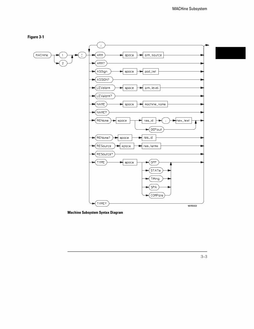
Machine Subsystem Syntax Diagram
Figure 3-1
MACHine Subsystem
3–3
Table 3-1 Machine Subsystem Parameter Values
Parameter Value
arm_source {RUN | INTermodule | MACHine {1|2}}
pod_list {NONE | <pod_num>[, <pod_num>]...}
pod_num integer from 1 to 12
arm_level integer from 1 to 11 representing sequence level
machine_name string of up to 10 alphanumeric characters
res_id {<state_terms>} for state analyzeror{<state_terms>|EDGE{1|2}} for timing analyzer
new_text string of up to 8 alphanumeric characters
state_terms {A|B|C|D|E|F|G|H|I|J|RANGE{1|2}|TIMER{1|2}}
res_terms {<res_id>[,<res_id>]...}
MACHine
Selector :MACHine<N>
The MACHine <N> selector specifies which of the two analyzers (machines)available in the module the commands or queries following will refer to.Because the MACHine<N> command is a root level command, it will normallyappear as the first element of a compound header.
<N> {1|2} (the machine number)
Example OUTPUT XXX; ":MACHINE1:NAME ’TIMING’"
MACHine SubsystemMACHine
3–4
ARM
Command :MACHine{1|2}:ARM <arm_source>
The ARM command specifies the arming source of the specified analyzer(machine). The RUN option disables the arm source. For example, if you donot want to use either the intermodule bus or the other machine to arm thecurrent machine, you specify the RUN option.
If you are using an Agilent Technologies 16500C mainframe, you can set upOR’d Triggering by arming the module from INTermodule when intermoduleis set to Group Run with OR TRIGGER. See the Agilent Technologies
16500C Programmer’s Guide for details.
<arm_source> {RUN|INTermodule|MACHine{1|2}}
Example OUTPUT XXX;":MACHINE1:ARM MACHINE2"
Query :MACHine{1|2}:ARM?
The ARM query returns the source that the current analyzer (machine) willbe armed by.
Returned Format [:MACHine{1|2}:ARM] <arm_source>
Example OUTPUT XXX;":MACHINE1:ARM?"
MACHine SubsystemARM
3–5
ASSign
Command :MACHine{1|2}:ASSign <pod_list>
The ASSign command assigns pods to a particular analyzer (machine). TheASSign command will assign two pods for each pod number you specifybecause pods must be assigned to analyzers in pairs. NONE clears all podsfrom the specified analyzer (machine) and places them in the "unassigned"category.
If you specify a pod number greater than currently available, the logicanalysis system generates an "Argument out of range" error.
<pod_list> {NONE | <pod #>[, <pod #>]...}
<pod#> an integer from 1 to 12
Example This example assigns pod pairs 1/2 and 5/6 to machine 1:
OUTPUT XXX;":MACHINE1:ASSIGN 5, 2, 1"
Query :MACHine{1|2}:ASSign?
The ASSign query returns which pods are assigned to the current analyzer(machine).
Returned Format [:MACHine{1|2}:ASSign] <pod_list><NL>
Example OUTPUT XXX;":MACHINE1:ASSIGN?"
MACHine SubsystemASSign
3–6
LEVelarm
Command :MACHine{1|2}:LEVelarm <arm_level>
The LEVelarm command allows you to specify the sequence level for aspecified machine that will be armed by the Intermodule Bus or the othermachine. This command is only valid if the specified machine is on and thearming source is not set to RUN with the ARM command.
<arm_level> integer from 1 to 11 representing sequence level
Example OUTPUT XXX;":MACHINE1:LEVELARM 2"
Query :MACHine{1|2}:LEVelarm?
The LEVelarm query returns the current sequence level receiving the armingfor a specified machine.
Returned Format [:MACHine{1|2}:LEVelarm] <arm_level><NL>
Example OUTPUT XXX;":MACHINE1:LEVELARM?"
MACHine SubsystemLEVelarm
3–7
NAME
Command :MACHine{1|2}:NAME <machine_name>
The NAME command allows you to assign a name of up to 10 characters to aparticular analyzer (machine) for easier identification. Spaces are validcharacters.
<machine_name> string of up to 10 alphanumeric characters
Example OUTPUT XXX;":MACHINE1:NAME ’DRAM TEST’"
Query :MACHine{1|2}:NAME?
The NAME query returns the current analyzer name as an ASCII string.Returned Format [:MACHine{1|2}:NAME] <machine name><NL>
Example OUTPUT XXX;":MACHINE1:NAME?"
REName
Command :MACHine{1|2}:REName {{<res_id>, <new_text>} |DEFault}
The REName command allows you to assign a specific name of up to eightcharacters to terms A through J, Range 1 and 2, Timer 1 and 2, and Edge 1and 2. The terms do not have to be assigned to the specified machine. TheDEFault option sets all resource term names to the default names assignedwhen turning on the instrument.
MACHine SubsystemNAME
3–8
<res_id> {<state_terms>} for state analyzer{<state_terms>|EDGE{1|2}} for timing analyzer
<new_text> string of up to 8 alphanumeric characters
<state_terms> {A|B|C|D|E|F|G|H|I|J| RANGe1 | RANGe2 | TIMer1 | TIMer2}
Example OUTPUT XXX;":MACHINE1:RENAME A,’DATA’"
Query :MACHine{1|2}:RENAME? <res_id>
The REName query returns the current names for specified terms assignedto the specified analyzer.
Returned Format [:MACHine{1|2}:RENAME] <res_id>,<new_text><NL>
Example OUTPUT XXX;":MACHINE1:RENAME? D"
RESource
Command :MACHine{1|2}:RESource {<res_id>[,<res_id>]...}
The RESource command allows you to assign resource terms A through J,Range 1 and 2, and Timer 1 and 2 to a particular analyzer.
In the timing analyzer only, two additional resource terms are available.These terms are Edge 1 and 2. These terms are always assigned to themachine that is configured as the timing analyzer.
<res_id> <state_terms> for state analyzer {<state_terms>|EDGE{1|2}} for timing analyzer
<state_terms> {A|B|C|D|E|F|G|H|I|J|RANGe1| RANGe2 | TIMer1|TIMer2}
MACHine SubsystemRESource
3–9
Example OUTPUT XXX;":MACHINE1:RESOURCE A,C,RANGE1"
Query :MACHine{1|2}:RESOURCE?
The RESource query returns the current resource terms assigned to thespecified analyzer. If no resource terms are assigned, no <res_id> is returned.
Returned Format [:MACHine{1|2}:RESOURCE] <res_id>[,<res_id>,...]<NL>
Example OUTPUT XXX;":MACHINE1:RESOURCE?"
TYPE
Command :MACHine{1|2}:TYPE <analyzer type>
The TYPE command specifies what type a specified analyzer (machine) willbe. The analyzer types are state or timing. State Compare (COMPare) andSPA are considered to be state analyzers because they use an external clock,but need to specified as COMPare or SPA.
The TYPE command also allows you to turn off a particular machine.
Only one timing analyzer can be specified at a time.
<analyzertype>
{OFF|COMPare|SPA|STATe|TIMing}
Example OUTPUT XXX;":MACHINE1:TYPE STATE"
MACHine SubsystemTYPE
3–10

Query :MACHine{1|2}:TYPE?
The TYPE query returns the current analyzer type for the specified analyzer.Returned Format [:MACHine{1|2}:TYPE] <analyzer type><NL>
Example OUTPUT XXX;":MACHINE1:TYPE?"
MACHine SubsystemTYPE
3–11

3–12
4
WLISt Subsystem
Introduction
The commands in the WLISt (Waveforms/LISting) subsystem controlthe X and O marker placement on the waveforms portion of theTiming/State mixed mode display. The XSTate and OSTate queriesreturn what states the X and O markers are on. Because the markerscan only be placed on the timing waveforms, the queries return whatstate (state acquisition memory location) the marked pattern is storedin.
In order to have mixed mode, one machine must be a state analyzerwith time tagging on (use MACHine<N>:STRigger:TAG TIME ).
• DELay
• INSert
• LINE
• MINus
• OSTate
• OTIMe
• OVERlay
• PLUS
• RANGe
• REMove
• XOTime
• XSTate
• XTIMe
4–2
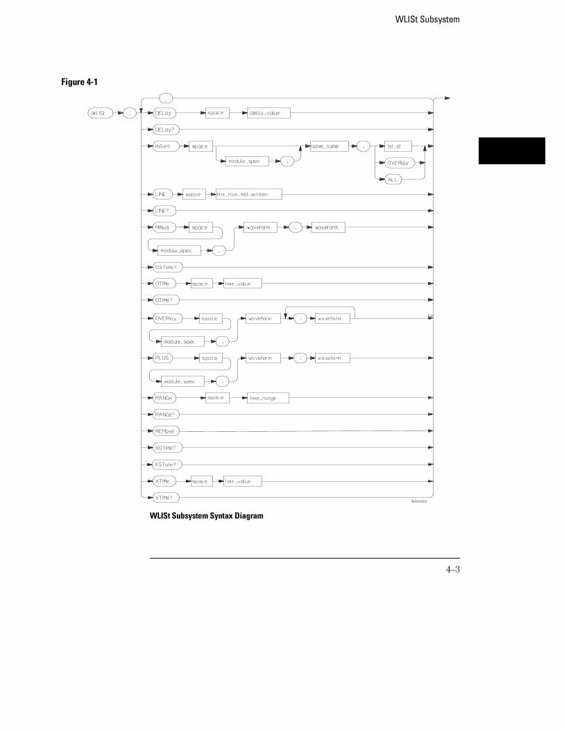
WLISt Subsystem Syntax Diagram
Figure 4-1
WLISt Subsystem
4–3
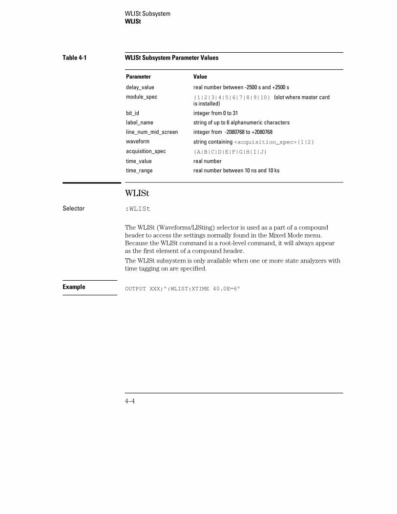
Table 4-1 WLISt Subsystem Parameter Values
Parameter Value
delay_value real number between -2500 s and +2500 s
module_spec {1|2|3|4|5|6|7|8|9|10} (slot where master cardis installed)
bit_id integer from 0 to 31
label_name string of up to 6 alphanumeric characters
line_num_mid_screen integer from -2080768 to +2080768
waveform string containing <acquisition_spec>{1|2}
acquisition_spec {A|B|C|D|E|F|G|H|I|J}
time_value real number
time_range real number between 10 ns and 10 ks
WLISt
Selector :WLISt
The WLISt (Waveforms/LISting) selector is used as a part of a compoundheader to access the settings normally found in the Mixed Mode menu.Because the WLISt command is a root-level command, it will always appearas the first element of a compound header.
The WLISt subsystem is only available when one or more state analyzers withtime tagging on are specified.
Example OUTPUT XXX;":WLIST:XTIME 40.0E −6"
WLISt SubsystemWLISt
4–4
DELay
Command :WLISt:DELay <delay_value>
The DELay command specifies the amount of time between the timingtrigger and the horizontal center of the the timing waveform display. Theallowable values for delay are −2500 s to +2500 s.
<delay_value> real number between −2500 s and +2500 s
Example OUTPUT XXX;":WLIST:DELAY 100E −6"
Query :WLISt:DELay?
The DELay query returns the current time offset (delay) value from thetrigger.
Returned Format [:WLISt:DELay] <delay_value><NL>
Example OUTPUT XXX;":WLIST:DELAY?"
WLISt SubsystemDELay
4–5
INSert
Command :WLISt:INSert [<module_spec>,]<label_name>[,{<bit_id>|OVERlay|ALL}]
The INSert command inserts waveforms in the timing waveform display. Thewaveforms are added from top to bottom up to a maximum of 96 waveforms.Once 96 waveforms are present, each time you insert another waveform, itreplaces the last waveform.
Time-correlated waveforms from the oscilloscope and another logic analyzermodule can also be inserted in the logic analyzer’s timing waveforms display.Oscilloscope waveforms occupy the same display space as three logicanalyzer waveforms. When inserting waveforms from the oscilloscope oranother logic analyzer module, the optional first parameter must be used,which is the module specifier. 1 through 10 corresponds to modules Athrough J. If you do not specify the module, the selected module is assumed.
The second parameter specifies the label name that will be inserted. Theoptional third parameter specifies the label bit number, overlay, or all. If anumber is specified, only the waveform for that bit number is added to thescreen.
If you specify OVERlay, all the bits of the label are displayed as a compositeoverlaid waveform. If you specify ALL, all the bits are displayed sequentially.
If you do not specify the third parameter, ALL is assumed.
<module_spec> {1|2|3|4|5|6|7|8|9|10}
<label_name> string of up to 6 alphanumeric characters
<bit_id> integer from 0 to 31
Example OUTPUT XXX;":WLIST:INSERT 3, ’WAVE’,9"
WLISt SubsystemINSert
4–6
Inserting Oscilloscope Waveforms
Command :WLISt:INSert <module_spec>,<label_name>
This inserts a waveform from an oscilloscope to the timing waveforms display.
<module_spec> {1|2|3|4|5|6|7|8|9|10} slot in which master card is installed
<label_name> string of one alpha and one numeric character, identical to that on theoscilloscope waveform display.
Example OUTPUT XXX;":WLIST:INSERT 3, ’C1’"
LINE
Command :WLISt:LINE <line_num_mid_screen>
The LINE command allows you to scroll the timing analyzer listing vertically.The command specifies the state line number relative to the trigger. Theanalyzer then highlights the specified line at the center of the screen.
<line_num_mid_screen>
integer from -2080768 to +2080768.
Example OUTPUT XXX;":WLIST:LINE 0"
WLISt SubsystemLINE
4–7
Query :WLISt:LINE?
The LINE query returns the line number for the state currently in the datalisting roll box at center screen.
Returned Format [:WLISt:LINE] <line_num_mid_screen><NL>
Example OUTPUT XXX;":WLIST:LINE?"
MINus
Command :WLISt:MINus <module_spec>,<waveform>,<waveform>
The MINus command inserts time-correlated A−B (A minus B) oscilloscopewaveforms on the screen. The first parameter is the module specifier wherethe oscilloscope module resides, where 1 through 10 refers to slots A throughJ. The next two parameters specify which waveforms will be subtracted fromeach other.
MINus only inserts oscilloscope waveforms. It cannot be used with analyzerwaveforms.
<module_spec> {1|2|3|4|5|6|7|8|9|10} (slot where master card is located)
<waveform> string containing <acquisition_spec>{1|2}
<acquisition_spec>
{A|B|C|D|E|F|G|H|I|J} (slot where acquisition card is located)
Example OUTPUT XXX; ":WLIST:MINUS 1,’A1’,’A2’"
WLISt SubsystemMINus
4–8

OSTate
Query :WLISt:OSTate?
The OSTate query returns the state where the O marker is positioned. If datais not valid, the query returns 2147483647.
Returned Format [:WLISt:OSTate] <state_num><NL>
<state_num> integer
Example OUTPUT XXX;":WLIST:OSTATE?"
OTIMe
Command :WLISt:OTIMe <time_value>
The OTIMe command positions the O marker on the timing waveforms in themixed mode display. If the data is not valid, the command performs noaction.
<time_value> real number
Example OUTPUT XXX;":WLIST:OTIME 40.0E −6"
WLISt SubsystemOSTate
4–9
Query :WLISt:OTIMe?
The OTIMe query returns the O marker position in time. If data is not valid,the query returns 9.9E37.
Returned Format [:WLISt:OTIMe] <time_value><NL>
Example OUTPUT XXX;":WLIST:OTIME?"
OVERlay
Command :WLISt:OVERlay <module_number>,<label>[,<label>]...
The OVERlay command overlays two or more oscilloscope waveforms andadds the resultant waveform to the current waveform display. The firstparameter of the command syntax specifies which slot contains theoscilloscope time base card. The next parameters are the labels of thewaveforms that are to be overlaid.
Overlay only inserts oscilloscope waveforms. It cannot be used with analyzerwaveforms.
<module_spec> {1|2|3|4|5|6|7|8|9|10} (slot where master card is located)
<waveform> string containing <acquisition_spec>{1|2}
<acquisition_spec>
{A|B|C|D|E|F|G|H|I|J} (slot where acquisition card is located)
Example OUTPUT XXX;":WLIST:OVERLAY 3, ’C1’,’B1’"
WLISt SubsystemOVERlay
4–10
PLUS
Command :WLISt:PLUS <module_spec>,<waveform>,<waveform>
The PLUS command inserts time-correlated A+B oscilloscope waveforms onthe screen. The first parameter specifies which slot is the oscilloscopemodule. 1 through 10 refers to slots A through J. The next two parametersspecify which waveforms will be added to each other.
PLUS only inserts oscilloscope waveforms. It cannot be used with analyzerwaveforms.
<module_spec> {1|2|3|4|5|6|7|8|9|10} (slot where master card is located)
<waveform> string containing <acquisition_spec>{1|2}
<acquisition_spec>
{A|B|C|D|E|F|G|H|I|J} (slot where acquisition card is located)
Example OUTPUT XXX; ":WLIST:PLUS 1,’A1’,’A2’"
WLISt SubsystemPLUS
4–11
RANGe
Command :WLISt:RANGe <time_value>
The RANGe command specifies the full-screen time in the timing waveformmenu. It is equivalent to ten times the seconds per division setting on thedisplay. The allowable values for RANGe are from 10 ns to 10 ks.
<time_range> real number between 10 ns and 10 ks
Example OUTPUT XXX;":WLIST:RANGE 100E −9"
Query :WLISt:RANGe?
The RANGe query returns the current full-screen time.Returned Format [:WLISt:RANGe] <time_value><NL>
Example OUTPUT XXX;":WLIST:RANGE?"
REMove
Command :WLISt:REMove
The REMove command deletes all waveforms from the display.
Example OUTPUT XXX;":WLIST:REMOVE"
WLISt SubsystemRANGe
4–12
XOTime
Query :WLISt:XOTime?
The XOTime query returns the time from the X marker to the O marker. Ifdata is not valid, the query returns 9.9E37.
Returned Format [:WLISt:XOTime] <time_value><NL>
<time_value> real number
Example OUTPUT XXX;":WLIST:XOTIME?"
XSTate
Query :WLISt:XSTate?
The XSTate query returns the state where the X marker is positioned. If datais not valid, the query returns 2147483647.
Returned Format [:WLISt:XSTate] <state_num><NL>
<state_num> integer
Example OUTPUT XXX;":WLIST:XSTATE?"
WLISt SubsystemXOTime
4–13
XTIMe
Command :WLISt:XTIMe <time_value>
The XTIMe command positions the X marker on the timing waveforms in themixed mode display. If the data is not valid, the command performs noaction.
<time_value> real number
Example OUTPUT XXX;":WLIST:XTIME 40.0E −6"
Query :WLISt:XTIMe?
The XTIMe query returns the X marker position in time. If data is not valid,the query returns 9.9E37.
Returned Format [:WLISt:XTIMe] <time_value><NL>
Example OUTPUT XXX;":WLIST:XTIME?"
WLISt SubsystemXTIMe
4–14
5
SFORmat Subsystem
Introduction
The SFORmat subsystem contains the commands available for theState Format menu in the 16557D logic analyzer module. Thesecommands are:
• CLOCk
• LABel
• MASTer
• MOPQual
• MQUal
• REMove
• SETHold
• SLAVe
• SOPQual
• SQUal
• THReshold
5–2
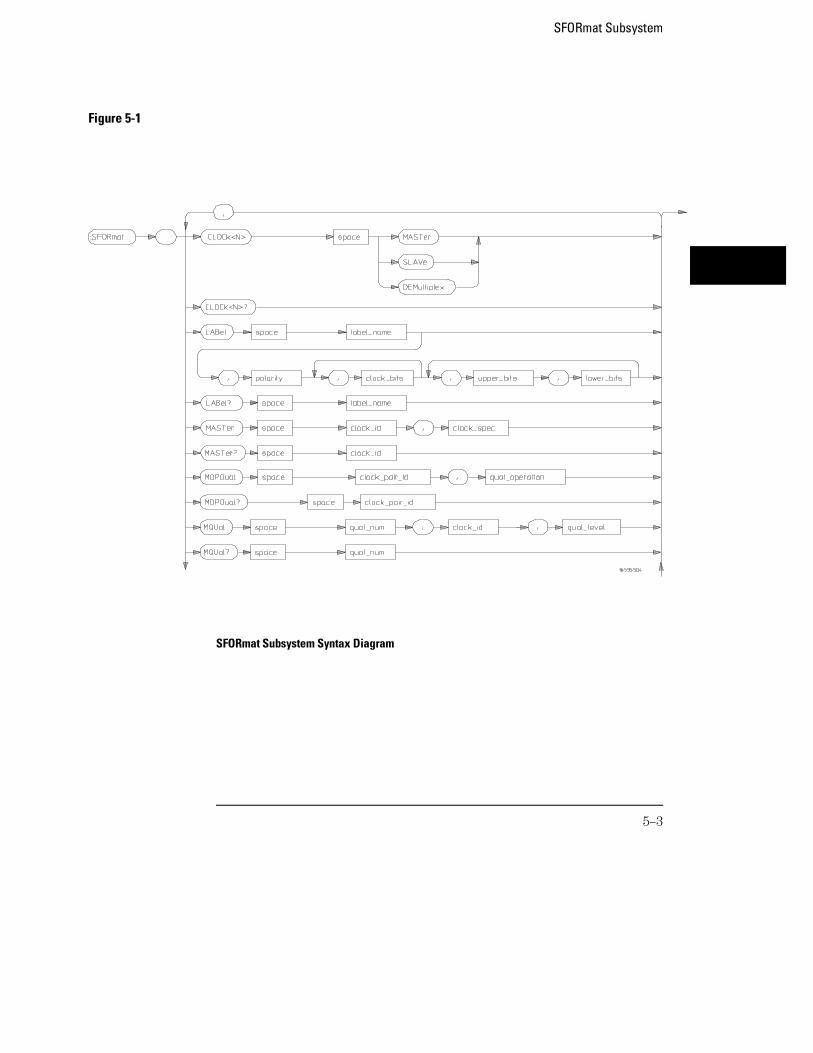
Figure 5-1
SFORmat Subsystem Syntax Diagram
SFORmat Subsystem
5–3
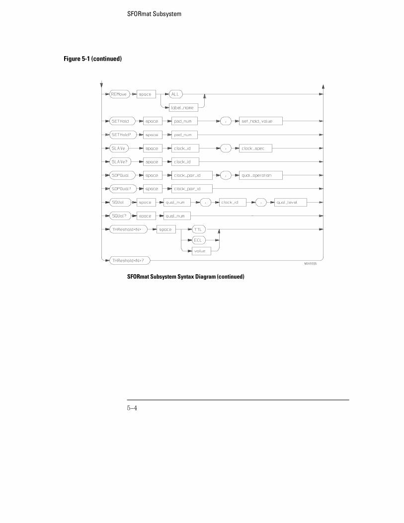
Figure 5-1 (continued)
SFORmat Subsystem Syntax Diagram (continued)
SFORmat Subsystem
5–4
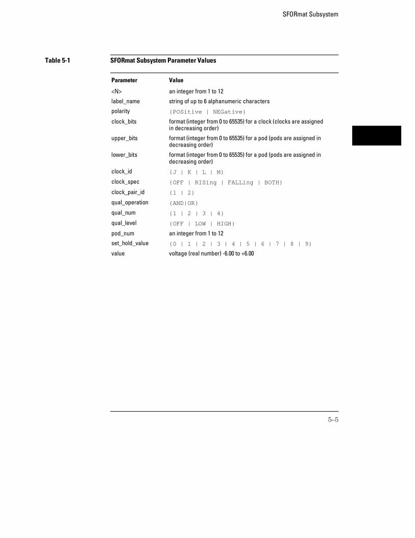
Table 5-1 SFORmat Subsystem Parameter Values
Parameter Value
<N> an integer from 1 to 12
label_name string of up to 6 alphanumeric characters
polarity {POSitive | NEGative}
clock_bits format (integer from 0 to 65535) for a clock (clocks are assignedin decreasing order)
upper_bits format (integer from 0 to 65535) for a pod (pods are assigned indecreasing order)
lower_bits format (integer from 0 to 65535) for a pod (pods are assigned indecreasing order)
clock_id {J | K | L | M}
clock_spec {OFF | RISing | FALLing | BOTH}
clock_pair_id {1 | 2}
qual_operation {AND|OR}
qual_num {1 | 2 | 3 | 4}
qual_level {OFF | LOW | HIGH}
pod_num an integer from 1 to 12
set_hold_value {0 | 1 | 2 | 3 | 4 | 5 | 6 | 7 | 8 | 9}
value voltage (real number) -6.00 to +6.00
SFORmat Subsystem
5–5
SFORmat
Selector :MACHine{1|2}:SFORmat
The SFORmat (State Format) selector is used as a part of a compoundheader to access the settings in the State Format menu. It always follows theMACHine selector because it selects a branch directly below the MACHinelevel in the command tree.
Example OUTPUT XXX;":MACHINE2:SFORMAT:MASTER J, RISING"
CLOCk
Command :MACHine{1|2}:SFORmat:CLOCk<N> <clock_mode>
The CLOCk command selects the clocking mode for a given pod when thepod is assigned to the state analyzer. When the MASTer option is specified,the pod will sample all channels on the master clock. When the SLAVe optionis specified, the pod will sample all channels on the slave clock. When theDEMultiplex option is specified, only one pod of a pod pair can acquire data.The bits of the selected pod will be clocked by the demultiplex master forlabels with bits assigned under the Master pod. The same bits will be clockedby the demultiplex slave for labels with bits assigned under the Slave pod.The master clock always follows the slave clock when both are used.
<N> an integer from 1 to 12
<clock_mode> {MASTer | SLAVe | DEMultiplex}
Example OUTPUT XXX;":MACHINE1:SFORMAT:CLOCK2 MASTER"
SFORmat SubsystemSFORmat
5–6
Query :MACHine{1|2}:SFORmat:CLOCk<N>?
The CLOCk query returns the current clocking mode for a given pod.Returned Format [:MACHine{1|2}:SFORmat:CLOCK<N>] <clock_mode><NL>
Example OUTPUT XXX; ":MACHINE1:SFORMAT:CLOCK2?"
LABel
Command :MACHine{1|2}:SFORmat:LABel <name>[,<polarity>,<clock_bits>, <upper_bits>,<lower_bits>[,<upper_bits>,<lower_bits>]...]
The LABel command allows you to specify polarity and assign channels tonew or existing labels. If the specified label name does not match an existinglabel name, a new label will be created.
The order of the pod-specification parameters is significant. The first onelisted will match the highest-numbered pod assigned to the machine you’reusing. Each pod specification after that is assigned to the next highest-numbered pod. This way the specifications match the left-to-rightdescending order of the pods you see on the Format display. Not includingenough pod specifications results in the lowest numbered pod(s) beingassigned a value of zero (all channels excluded). If you include more podspecifications than there are pods for that machine, the extra ones will beignored. However, an error is reported any time more than 22 podspecifications are listed.
The polarity can be specified at any point after the label name.
Because pods contain 16 channels, the format value for a pod must bebetween 0 and 65535 (216−1). When giving the pod assignment in binary,each bit will correspond to a single channel. A "1" in a bit position means theassociated channel in that pod is assigned to the label. A "0" in a bit positionmeans the associated channel in that pod is excluded from the label. Leadingzeroes may be omitted. For example, assigning #B1111001100 is equivalentto entering "......****..**.." through the touchscreen.
A label can not have a total of more than 32 channels assigned to it.
SFORmat SubsystemLABel
5–7
<name> string of up to 6 alphanumeric characters
<polarity> {POSitive | NEGative}
<clock_bits> format (integer from 0 to 65535) for a clock (clocks are assigned indecreasing order)
<upper_bits><lower_bits>
format (integer from 0 to 65535) for a pod (pods are assigned in decreasingorder)
Example
510 OUTPUT XXX;":MACHINE2:SFORMAT:LABEL ’STAT’, POSITIVE, 0,127,40312"520 OUTPUT XXX;":MACHINE2:SFORMAT:LABEL ’SIG 1’, #B11,#B0000000011111111,
#B0000000000000000 "
Query :MACHine{1|2}:SFORmat:LABel? <name>
The LABel query returns the current specification for the selected (by name)label. If the label does not exist, nothing is returned. The polarity is alwaysreturned as the first parameter. Numbers are always returned in decimalformat. Label names are case-sensitive.
Returned Format [:MACHine{1|2}:SFORmat:LABel] <name>,<polarity>[, <assignment>]...<NL>
Example OUTPUT XXX;":MACHINE2:SFORMAT:LABEL? ’DATA’"
SFORmat SubsystemLABel
5–8
MASTer
Command :MACHine{1|2}:SFORmat:MASTer <clock_id>,<clock_spec>
The MASTer clock command allows you to specify a master clock for a givenmachine. The master clock is used in all clocking modes (Master, Slave, andDemultiplexed). Each command deals with only one clock (J,K,L,M);therefore, a complete clock specification requires four commands, one foreach clock. Edge specifications (RISing, FALLing, or BOTH) are ORed.
At least one clock edge must be specified.
<clock_id> {J|K|L|M}
<clock_spec> {OFF|RISing|FALLing|BOTH}
Example OUTPUT XXX;":MACHINE2:SFORMAT:MASTER J, RISING"
Query :MACHine{1|2}:SFORmat:MASTer? <clock_id>
The MASTer query returns the clock specification for the specified clock.Returned Format [:MACHine{1|2}:SFORmat:MASTer] <clock_id>,<clock_spec><NL>
Example OUTPUT XXX;":MACHINE2:SFORMAT:MASTER? <clock_id>"
SFORmat SubsystemMASTer
5–9
MOPQual
Command :MACHine{1|2}:SFORmat:MOPQual <clock_pair_id>,<qual_operation>
The MOPQual (master operation qualifier) command allows you to specifyeither the AND or the OR operation between master clock qualifier pair 1/2,or between master clock qualifier pair 3/4. For example, you can specify amaster clock operation qualifier 1 AND 2.
<clock_pair_id>
{1|2} where 2 indicates qualifier pair 3/4.
<qual_operation>
{AND|OR}
Example OUTPUT XXX;":MACHINE1:SFORMAT:MOPQUAL 1,AND"
Query :MACHine{1|2}:SFORmat:MOPQual? <clock_pair_id>
The MOPQual query returns the operation qualifier specified for the masterclock.
Returned Format [:MACHine{1|2}:SFORmat:MOPQUal <clock_pair_id>]<qual_operation><NL>
Example OUTPUT XXX;":MACHine1:SFORMAT:MOPQUAL? 1"
SFORmat SubsystemMOPQual
5–10
MQUal
Command :MACHine{1|2}:SFORmat:MQUal <qual_num>,<clock_id>,<qual_level>
The MQUal (master qualifier) command allows you to specify the levelqualifier for the master clock.
<qual_num> {1|2|3|4}
<clock_id> {J|K|L|M}
<qual_level> {OFF|LOW|HIGH}
Example OUTPUT XXX;":MACHINE2:SFORMAT:MQUAL 1,J,LOW"
Query :MACHine{1|2}:SFORmat:MQUal? <qual_num>
The MQUal query returns the qualifier specified for the master clock.Returned Format [:MACHine{1|2}:SFORmat:MQUal] <qual_level><NL>
Example OUTPUT XXX;":MACHINE2:SFORMAT:MQUAL? 1"
SFORmat SubsystemMQUal
5–11
REMove
Command :MACHine{1|2}:SFORmat:REMove {<name>|ALL}
The REMove command allows you to delete all labels or any one label for agiven machine.
<name> string of up to 6 alphanumeric characters
Example OUTPUT XXX;":MACHINE1:SFORMAT:REMOVE ’A’"OUTPUT XXX;":MACHINE2:SFORMAT:REMOVE ALL"
SETHold
Command :MACHine{1|2}:SFORmat:SETHold<pod_num>,<set_hold_value>
The SETHold (setup/hold) command allows you to set the setup and holdspecification for the state analyzer.
Even though the command requires integers to specify the setup and hold,the query returns the current settings in a string. For example, if you sendthe integer 0 for the setup and hold value, the query will return 3.0/0.0 ns asan ASCII string when you have one clock and one edge specified.
SFORmat SubsystemREMove
5–12
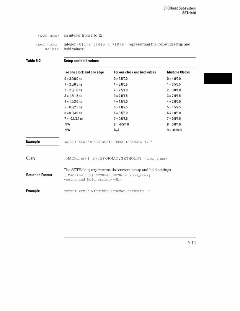
<pod_num> an integer from 1 to 12
<set_hold_value>
integer {0|1|2|3|4|5|6|7|8|9} representing the following setup andhold values:
Table 5-2 Setup and hold values
For one clock and one edge For one clock and both edges Multiple Clocks
0 = 3.0/0.0 ns 0 = 3.5/0.0 0 = 4.0/0.0
1 = 2.5/0.5 ns 1 = 3.0/0.5 1 = 3.5/0.5
2 = 2.0/1.0 ns 2 = 2.5/1.0 2 = 3.0/1.0
3 = 1.5/1.5 ns 3 = 2.0/1.5 3 = 2.5/1.5
4 = 1.0/2.0 ns 4 = 1.5/2.0 4 = 2.0/2.0
5 = 0.5/2.5 ns 5 = 1.0/2.5 5 = 1.5/2.5
6 = 0.0/3.0 ns 6 = 0.5/3.0 6 = 1.0/3.0
7 = -0.5/3.5 ns 7 = 0.0/3.5 7 = 0.5/3.5
N/A 8 = -0.5/4.0 8 = 0.0/4.0
N/A N/A 9 = -0.5/4.5
Example OUTPUT XXX;":MACHINE2:SFORMAT:SETHOLD 1,2"
Query :MACHine{1|2}:SFORMAT:SETHOLD? <pod_num>
The SETHold query returns the current setup and hold settings.Returned Format [:MACHine{1|2}:SFORmat:SETHold <pod_num>]
<setup_and_hold_string><NL>
Example OUTPUT XXX;":MACHINE2:SFORMAT:SETHOLD? 3"
SFORmat SubsystemSETHold
5–13
SLAVe
Command :MACHine{1|2}:SFORmat:SLAVe <clock_id>,<clock_spec>
The SLAVe clock command allows you to specify a slave clock for a givenmachine. The slave clock is only used in the Slave and Demultiplexedclocking modes. Each command deals with only one clock (J,K,L,M);therefore, a complete clock specification requires four commands, one foreach clock. Edge specifications (RISing, FALLing, or BOTH) are ORed.
When slave clock is being used at least one edge must be specified.
<clock_id> {J|K|L|M}
<clock_spec> {OFF|RISing|FALLing|BOTH}
Example OUTPUT XXX;":MACHINE2:SFORMAT:SLAVE J, RISING"
Query :MACHine{1|2}:SFORmat:SLAVe?<clock_id>
The SLAVe query returns the clock specification for the specified clock.Returned Format [:MACHine{1|2}:SFORmat:SLAVe] <clock_id>,<clock_spec><NL>
Example OUTPUT XXX;":MACHINE2:SFORMAT:SLAVE? K"
SFORmat SubsystemSLAVe
5–14
SOPQual
Command :MACHine{1|2}:SFORmat:SOPQual <clock_pair_id>,<qual_operation>
The SOPQual (slave operation qualifier) command allows you to specifyeither the AND or the OR operation between slave clock qualifier pair 1/2, orbetween slave clock qualifier pair 3/4. For example you can specify a slaveclock operation qualifier 1 AND 2.
<clock_pair_id>
{1|2} where 2 specifies qualifier pair 3/4
<qual_operation>
{AND|OR}
Example OUTPUT XXX;":MACHine2:SFORMAT:SOPQUAL 1,AND"
Query :MACHine{1|2}:SFORmat:SOPQual? <clock_pair_id>
The SOPQual query returns the operation qualifier specified for the slaveclock.
Returned Format [:MACHine{1|2}:SFORmat:SOPQual <clock_pair_id>]<qual_operation><NL>
Example OUTPUT XXX;":MACHiNE2:SFORMAT:SOPQUAL? 1"
SFORmat SubsystemSOPQual
5–15
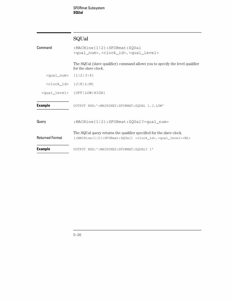
SQUal
Command :MACHine{1|2}:SFORmat:SQUal<qual_num>,<clock_id>,<qual_level>
The SQUal (slave qualifier) command allows you to specify the level qualifierfor the slave clock.
<qual_num> {1|2|3|4}
<clock_id> {J|K|L|M}
<qual_level> {OFF|LOW|HIGH}
Example OUTPUT XXX;":MACHINE2:SFORMAT:SQUAL 1,J,LOW"
Query :MACHine{1|2}:SFORmat:SQUal?<qual_num>
The SQUal query returns the qualifier specified for the slave clock.Returned Format [:MACHine{1|2}:SFORmat:SQUal] <clock_id>,<qual_level><NL>
Example OUTPUT XXX;":MACHINE2:SFORMAT:SQUAL? 1"
SFORmat SubsystemSQUal
5–16
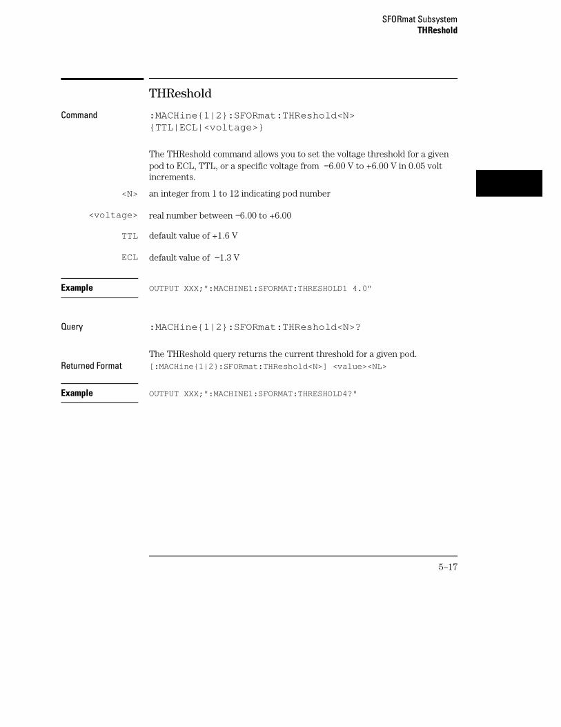
THReshold
Command :MACHine{1|2}:SFORmat:THReshold<N>{TTL|ECL|<voltage>}
The THReshold command allows you to set the voltage threshold for a givenpod to ECL, TTL, or a specific voltage from −6.00 V to +6.00 V in 0.05 voltincrements.
<N> an integer from 1 to 12 indicating pod number
<voltage> real number between −6.00 to +6.00
TTL default value of +1.6 V
ECL default value of −1.3 V
Example OUTPUT XXX;":MACHINE1:SFORMAT:THRESHOLD1 4.0"
Query :MACHine{1|2}:SFORmat:THReshold<N>?
The THReshold query returns the current threshold for a given pod.Returned Format [:MACHine{1|2}:SFORmat:THReshold<N>] <value><NL>
Example OUTPUT XXX;":MACHINE1:SFORMAT:THRESHOLD4?"
SFORmat SubsystemTHReshold
5–17

5–18
6
STRigger (STRace) Subsystem
Introduction
The STRigger subsystem contains the commands available for theState Trigger menu in the 16557D logic analyzer module. The StateTrigger subsystem will also accept the STRace selector as used inprevious Agilent Technologies 16500-Series logic analyzer modules toeliminate the need to rewrite programs containing STRace as theselector keyword. The STRigger subsystem commands are:
• ACQuisition
• BRANch
• CLEar
• FIND
• MLENgth
• RANGe
• SEQuence
• STORe
• TAG
• TAKenbranch
• TCONtrol
• TERM
• TIMER
• TPOSition
6–2
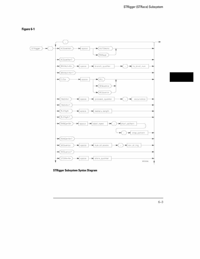
Figure 6-1
STRigger Subsystem Syntax Diagram
STRigger (STRace) Subsystem
6–3
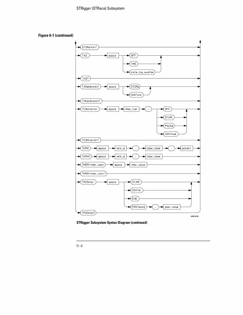
Figure 6-1 (continued)
STRigger Subsystem Syntax Diagram (continued)
STRigger (STRace) Subsystem
6–4
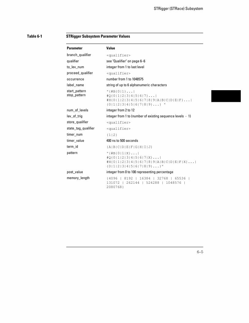
Table 6-1 STRigger Subsystem Parameter Values
Parameter Value
branch_qualifier <qualifier>
qualifier see "Qualifier" on page 6–6
to_lev_num integer from 1 to last level
proceed_qualifier <qualifier>
occurrence number from 1 to 1048575
label_name string of up to 6 alphanumeric characters
start_patternstop_pattern
"{#B{0|1}...|#Q{0|1|2|3|4|5|6|7}...|#H{0|1|2|3|4|5|6|7|8|9|A|B|C|D|E|F}...|{0|1|2|3|4|5|6|7|8|9}...} "
num_of_levels integer from 2 to 12
lev_of_trig integer from 1 to (number of existing sequence levels - 1)
store_qualifier <qualifier>
state_tag_qualifier <qualifier>
timer_num {1|2}
timer_value 400 ns to 500 seconds
term_id {A|B|C|D|E|F|G|H|I|J}
pattern "{#B{0|1|X}...|#Q{0|1|2|3|4|5|6|7|X}...|#H{0|1|2|3|4|5|6|7|8|9|A|B|C|D|E|F|X}...|{0|1|2|3|4|5|6|7|8|9}...}"
post_value integer from 0 to 100 representing percentage
memory_length {4096 | 8192 | 16384 | 32768 | 65536 |131072 | 262144 | 524288 | 1048576 |2080768}
STRigger (STRace) Subsystem
6–5
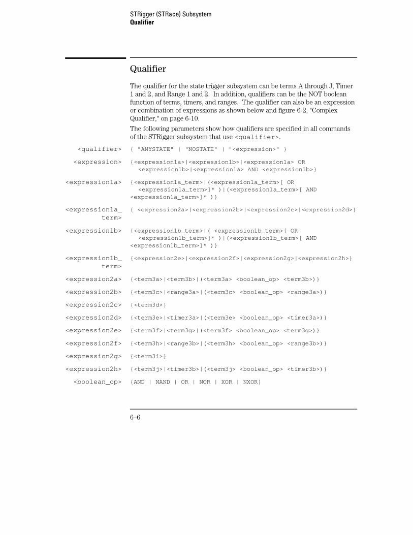
Qualifier
The qualifier for the state trigger subsystem can be terms A through J, Timer1 and 2, and Range 1 and 2. In addition, qualifiers can be the NOT booleanfunction of terms, timers, and ranges. The qualifier can also be an expressionor combination of expressions as shown below and figure 6-2, "ComplexQualifier," on page 6-10.
The following parameters show how qualifiers are specified in all commandsof the STRigger subsystem that use <qualifier> .
<qualifier> { "ANYSTATE" | "NOSTATE" | "<expression>" }
<expression> {<expression1a>|<expression1b>|<expression1a> OR <expression1b>|<expression1a> AND <expression1b>}
<expression1a> {<expression1a_term>|(<expression1a_term>[ OR <expression1a_term>]* )|(<expression1a_term>[ AND<expression1a_term>]* )}
<expression1a_term>
{ <expression2a>|<expression2b>|<expression2c>|<expression2d>}
<expression1b> {<expression1b_term>|( <expression1b_term>[ OR <expression1b_term>]* )|(<expression1b_term>[ AND<expression1b_term>]* )}
<expression1b_term>
{<expression2e>|<expression2f>|<expression2g>|<expression2h>}
<expression2a> {<term3a>|<term3b>|(<term3a> <boolean_op> <term3b>)}
<expression2b> {<term3c>|<range3a>|(<term3c> <boolean_op> <range3a>)}
<expression2c> {<term3d>}
<expression2d> {<term3e>|<timer3a>|(<term3e> <boolean_op> <timer3a>)}
<expression2e> {<term3f>|<term3g>|(<term3f> <boolean_op> <term3g>)}
<expression2f> {<term3h>|<range3b>|(<term3h> <boolean_op> <range3b>)}
<expression2g> {<term3i>}
<expression2h> {<term3j>|<timer3b>|(<term3j> <boolean_op> <timer3b>)}
<boolean_op> {AND | NAND | OR | NOR | XOR | NXOR}
STRigger (STRace) SubsystemQualifier
6–6
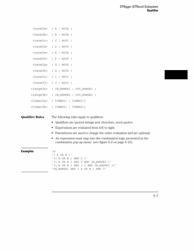
<term3a> { A | NOTA }
<term3b> { B | NOTB }
<term3c> { C | NOTC }
<term3d> { D | NOTD }
<term3e> { E | NOTE }
<term3f> { F | NOTF }
<term3g> { G | NOTG }
<term3h> { H | NOTH }
<term3i> { I | NOTI }
<term3j> { J | NOTJ }
<range3a> { IN_RANGE1 | OUT_RANGE1 }
<range3b> { IN_RANGE2 | OUT_RANGE2 }
<timer3a> { TIMER1< | TIMER1>}
<timer3b> { TIMER2< | TIMER2>}
Qualifier Rules The following rules apply to qualifiers:
• Qualifiers are quoted strings and, therefore, need quotes.
• Expressions are evaluated from left to right.
• Parentheses are used to change the order evaluation and are optional.
• An expression must map into the combination logic presented in thecombination pop-up menu (see figure 6-2 on page 6-10).
Examples ’A’’( A OR B )’’(( A OR B ) AND C )’’(( A OR B ) AND C AND IN_RANGE2 )’’(( A OR B ) AND ( C AND IN_RANGE1 ))’’IN_RANGE1 AND ( A OR B ) AND C’
STRigger (STRace) SubsystemQualifier
6–7
STRigger (STRace)
Selector :MACHine{1|2}:STRigger
The STRigger (STRace) (State Trigger) selector is used as a part of acompound header to access the settings found in the State Trace menu. Italways follows the MACHine selector because it selects a branch directlybelow the MACHine level in the command tree.
Example OUTPUT XXX;":MACHINE1:STRIGGER:TAG TIME"
ACQuisition
Command :MACHine{1|2}:STRigger:ACQuisition{AUTOmatic|MANual}
The ACQuisition command allows you to specify the acquisition mode for theState analyzer.
Example OUTPUT XXX;":MACHINE1:STRIGGER:ACQUISITION AUTOMATIC"
Query :MACHine{1|2}:STRigger:ACQuisition?
The ACQuisition query returns the current acquisition mode.Returned Format [:MACHine{1|2}:STRigger:ACQuisition] {AUTOmatic|MANual}<NL>
Example OUTPUT XXX;":MACHINE1:STRIGGER:ACQUISITION?"
STRigger (STRace) SubsystemSTRigger (STRace)
6–8
BRANch
Command :MACHine{1|2}:STRigger:BRANch<N><branch_qualifier>,<to_level_number>
The BRANch command defines the branch qualifier for a given sequencelevel. When this branch qualifier is matched, it will cause the sequencerto jump to the specified sequence level. The branch qualifier functions likethe "else on" branch of a sequence level.
The terms used by the branch qualifier (A through J) are defined by theTERM command. The meaning of IN_RANGE and OUT_RANGE isdetermined by the RANGE command.
Within the limitations shown by the syntax definitions, complex expressionsmay be formed using the AND and OR operators. Expressions are limited towhat you could manually enter through the State Trigger menu. Regardingparentheses, the syntax definitions on the next page show only the requiredones. Additional parentheses are allowed as long as the meaning of theexpression is not changed. Figure 6-2 shows a complex expression as seen inthe State Trigger menu.
Example The following statements are all correct and have the same meaning. Noticethat the conventional rules for precedence are not followed. The expressionsare evaluated from left to right.
OUTPUT XXX;":MACHINE1:STRIGGER:BRANCH1 ’C AND D OR F OR G’, 1"OUTPUT XXX;":MACHINE1:STRIGGER:BRANCH1 ’((C AND D) OR (F OR G))’, 1"OUTPUT XXX;":MACHINE1:STRIGGER:BRANCH1 ’F OR (C AND D) OR G’,1"
<N> integer from 1 to <number_of_levels>
<to_level_number>
integer from 1 to <number_of_levels>
<number_of_levels>
integer from 2 to the number of existing sequence levels (maximum 12)
<branch_qualifier>
<qualifier> see "Qualifier" on page 6-6
STRigger (STRace) SubsystemBRANch
6–9
Example OUTPUT XXX;":MACHINE1:STRIGGER:BRANCH1 ’ANYSTATE’, 3"OUTPUT XXX;":MACHINE1:STRIGGER:BRANCH2 ’A’, 7"OUTPUT XXX;":MACHINE1:STRIGGER:BRANCH3 ’((A OR B) OR NOTG)’, 1"
Query :MACHine{1|2}:STRigger:BRANch<N>?
The BRANch query returns the current branch qualifier specification for agiven sequence level.
Returned Format [:MACHine{1|2}:STRigger:BRANch<N>]<branch_qualifier>,<to_level_num><NL>
Example OUTPUT XXX;":MACHINE1:STRIGGER:BRANCH3?"
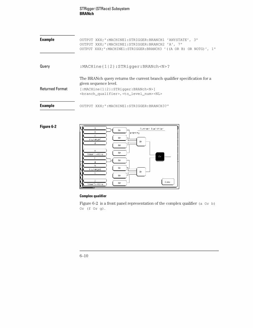
Figure 6-2
Complex qualifier
Figure 6-2 is a front panel representation of the complex qualifier (a Or b)Or (f Or g) .
STRigger (STRace) SubsystemBRANch
6–10
Example The following example would be used to specify the complex qualifier shownin figure 6-2.
OUTPUT XXX;":MACHINE1:STRIGGER:BRANCH1 ’((A OR B) AND (F ORG))’, 2"
Terms A through E, RANGE 1, and TIMER 1 must be grouped togetherand terms F through J, RANGE 2, and TIMER 2 must be grouped together.In the first level, terms from one group may not be mixed with terms from theother. For example, the expression ((A OR IN_RANGE2) AND (C OR G)) isnot allowed because the term C cannot be specified in the F, G, and I group.
In the first level, the operators you can use are AND, NAND, OR, NOR,XOR, NXOR. Either AND or OR may be used at the second level to join the twogroups together. It is acceptable for a group to consist of a single term.Thus, an expression like (B AND G) is legal, since the two operands are bothsimple terms from separate groups.
CLEar
Command :MACHine{1|2}:STRigger:CLEar{All|SEQuence|RESource}
The CLEar command allows you to clear all settings in the State Triggermenu, clear only the Sequence levels, or clear only the resource termpatterns. Cleared settings are replaced with the defaults.
Example OUTPUT XXX;":MACHINE1:STRIGGER:CLEAR RESOURCE"
STRigger (STRace) SubsystemCLEar
6–11
FIND
Command :MACHine{1|2}:STRigger:FIND<N><proceed_qualifier>,<occurrence>
The FIND command defines the proceed qualifier for a given sequence level.The qualifier tells the state analyzer when to proceed to the next sequencelevel. When this proceed qualifier is matched the specified number of times,the sequencer will proceed to the next sequence level. In the sequence levelwhere the trigger is specified, the FIND command specifies the triggerqualifier (see SEQuence command).
The terms A through J are defined by the TERM command. The meaning ofIN_RANGE and OUT_RANGE is determined by the RANGe command.Expressions are limited to what you could manually enter through the StateTrigger menu. Regarding parentheses, the syntax definitions below showonly the required ones. Additional parentheses are allowed as long as themeaning of the expression is not changed. See page 6-9 for a detailedexample.
<N> integer from 1 to (number of existing sequence levels −1)
<occurrence> integer from 1 to 1048575
<proceed_qualifier>
<qualifier> see "Qualifier" on page 6-6
Example OUTPUT XXX;":MACHINE1:STRIGGER:FIND1 ’ANYSTATE’, 1"OUTPUT XXX;":MACHINE1:STRIGGER:FIND3 ’((NOTA AND NOTB) ORG)’, 1"
STRigger (STRace) SubsystemFIND
6–12
Query :MACHine{1|2}:STRigger:FIND4?
The FIND query returns the current proceed qualifier specification for agiven sequence level.
Returned Format [:MACHine{1|2}:STRigger:FIND<N>]<proceed_qualifier>,<occurrence><NL>
Example OUTPUT XXX;":MACHINE1:STRIGGER:FIND<N>?"
MLENgth
Command :MACHine{1|2}:STRigger:MLENgth <memory_length>
The MLENgth command allows you to specify the analyzer memory depth.Valid memory depths range from 4096 states (or samples) through themaximum system memory depth minus 16384 states. Memory depth isaffected by acquisition mode. If the <memory_length> value sent with thecommand is not a legal value, the closest legal setting will be used.
<memory_length> {4096 | 8192 | 16384 | 32768 | 65536 | 131072 | 262144 | 524288 | 1048576 | 2080768}
Example OUTPUT XXX;":MACHINE1:STRIGGER:MLENGTH 262144"
Query :MACHine{1|2}:STRigger:MLENgth?
The MLENgth query returns the current analyzer memory depth selection.Returned Format [:MACHine{1|2}:STRigger:MLENgth] <memory_length><NL>
Example OUTPUT XXX;":MACHINE1:STRIGGER:MLENGTH?"
STRigger (STRace) SubsystemMLENgth
6–13
RANGe
Command :MACHine{1|2}:STRigger:RANGe<N> <label_name>,<start_pattern>,<stop_pattern>
The RANGe command allows you to specify a range recognizer term for thespecified machine. Since a range can only be defined across one label andsince a label must contain 32 or fewer bits, the value of the start pattern orstop pattern will be between (232)−1 and 0.
When these values are expressed in binary, they represent the bit values forthe label at one of the range recognizers’ end points. Don’t cares are notallowed in the end point pattern specifications.
<label_name> string of up to 6 alphanumeric characters
<start_pattern>
<stop_pattern>
"{#B{0|1} . . . |#Q{0|1|2|3|4|5|6|7} . . . |#H{0|1|2|3|4|5|6|7|8|9|A|B|C|D|E|F} . . . |{0|1|2|3|4|5|6|7|8|9} . . . }"
<N> {1 | 2}
Example OUTPUT XXX;":MACHINE1:STRIGGER:RANGE1 ’DATA’, ’127’, ’255’ "OUTPUT XXX;":MACHINE1:STRIGGER:RANGE2 ’ABC’, ’#B00001111’,’#HCF’ "
STRigger (STRace) SubsystemRANGe
6–14
Query :MACHine{1|2}:STRigger:RANGe<N>?
The RANGe query returns the range recognizer end point specifications forthe range.
Returned Format [:MACHine{1|2}:STRigger:RANGe<N>]<label_name>,<start_pattern>,<stop_pattern><NL>
Example OUTPUT XXX;":MACHINE1:STRIGGER:RANGE1?"
SEQuence
Command :MACHine{1|2}:STRigger:SEQuence <num_levels>,<trig_level>
The SEQuence command redefines the state analyzer trigger sequence.First, it deletes the current sequence. Then it inserts the number of levelsspecified, with default settings, and assigns the trigger to be at a specifiedsequence level. The number of levels may be between 2 and 12.
<num_levels> integer from 2 to 12
<trig_level> integer from 1 to (number of existing sequence levels − 1)
Example OUTPUT XXX;":MACHINE1:STRIGGER:SEQUENCE 4,3"
Query :MACHine{1|2}:STRigger:SEQuence?
The SEQuence query returns the current sequence specification.Returned Format [:MACHine{1|2}:STRigger:SEQuence] <num_levels>,
<trig_level><NL>
Example OUTPUT XXX;":MACHINE1:STRIGGER:SEQUENCE?"
STRigger (STRace) SubsystemSEQuence
6–15
STORe
Command :MACHine{1|2}:STRigger:STORe<N> <store_qualifier>
The STORe command defines the store qualifier for a given sequence level.Any data matching the STORe qualifier will be stored in memory as part ofthe current trace data. The qualifier may be a single term or a complexexpression. The terms A through J are defined by the TERM command. Themeaning of IN_RANGE1 and 2 and OUT_RANGE1 and 2 is determined by theRANGe command.
Expressions are limited to what you could manually enter through the StateTrigger menu. Regarding parentheses, the syntax definitions below showonly the required ones. Additional parentheses are allowed as long as themeaning of the expression is not changed.
A detailed example is provided starting on page 6-10.
<N> an integer from 1 to the number of existing sequence levels (maximum 12)
<store_qualifier>
<qualifier> see "Qualifier" on page 6-6
Example OUTPUT XXX;":MACHINE1:STRIGGER:STORE1 ’ANYSTATE’"OUTPUT XXX;":MACHINE1:STRIGGER:STORE2 ’OUT_RANGE1’"OUTPUT XXX;":MACHINE1:STRIGGER:STORE3 ’(NOTC AND NOTD ANDNOTI)’"
Query :MACHine{1|2}:STRigger:STORe<N>?
The STORe query returns the current store qualifier specification for a givensequence level <N>.
Returned Format [:MACHine{1|2}:STRigger:STORe<N>] <store_qualifier><NL>
Example OUTPUT XXX;":MACHINE1:STRIGGER:STORE4?"
STRigger (STRace) SubsystemSTORe
6–16
TAG
Command :MACHine{1|2}:STRigger:TAG{OFF|TIME| <state_tag_qualifier >}
The TAG command selects the type of count tagging (state or time) to beperformed during data acquisition. State tagging is indicated when theparameter is the state tag qualifier, which will be counted in the qualifiedstate mode. The qualifier may be a single term or a complex expression. Theterms A through J are defined by the TERM command. The termsIN_RANGE1 and 2 and OUT_RANGE1 and 2 are defined by the RANGecommand.
Expressions are limited to what you could manually enter through the StateTrigger menu. Regarding parentheses, the syntax definitions below showonly the required ones. Additional parentheses are allowed as long as themeaning of the expression is not changed. A detailed example is providedstarting on page 6-10.
<state_tag_qualifier>
<qualifier> see "Qualifier" on page 6-6
Example OUTPUT XXX;":MACHINE1:STRIGGER:TAG OFF"OUTPUT XXX;":MACHINE1:STRIGGER:TAG TIME"OUTPUT XXX;":MACHINE1:STRIGGER:TAG ’(IN_RANGE OR NOTF)’"OUTPUT XXX;":MACHINE1:STRIGGER:TAG ’((IN_RANGE OR A) AND E)’"
Query :MACHine{1|2} :STRigger:TAG?
The TAG query returns the current count tag specification.Returned Format [:MACHine{1|2}:STRigger:TAG]
{OFF|TIME|<state_tag_qualifier>}<NL>
Example OUTPUT XXX;":MACHINE1:STRIGGER:TAG?"
STRigger (STRace) SubsystemTAG
6–17
TAKenbranch
Command :MACHine{1|2}:STRigger:TAKenbranch {STORe|NOSTore}
The TAKenbranch command allows you to specify whether the state causingthe branch is stored or not stored for the specified machine. The statescausing the branch are defined by the BRANch and FIND commands.
Example OUTPUT XXX;":MACHINE2:STRIGGER:TAKENBRANCH STORE"
Query :MACHine{1|2}:STRigger:TAKenbranch?
The TAKenbranch query returns the current setting.Returned Format [:MACHine{1|2}:STRigger:TAKenbranch] {STORe|NOSTore}<NL>
Example OUTPUT XXX;":MACHINE2:STRIGGER:TAKENBRANCH?
STRigger (STRace) SubsystemTAKenbranch
6–18
TCONtrol
Command :MACHine{1|2}:STRigger:TCONtrol<N> <timer_num>,{OFF|STARt|PAUSe|CONTinue}
The TCONtrol (timer control) command allows you to turn off, start, pause,or continue the timer for the specified level. The time value of the timer isdefined by the TIMER command. There are two timers and they are availablefor either machine but not both machines simultaneously.
<N> integer from 1 to the number of existing sequence levels (maximum 12)
<timer_num> {1|2}
Example OUTPUT XXX;":MACHINE2:STRIGGER:TCONTROL6 1, PAUSE"
Query :MACHine{1|2}:STRigger:TCONTROL<N>? <timer_num>
The TCONtrol query returns the current TCONtrol setting of the specifiedlevel.
Returned Format [:MACHine{1|2}:STRigger:TCONTROL<N> <timer_num>]{OFF|STARt|PAUSe|CONTinue}<NL>
Example OUTPUT XXX;":MACHINE2:STRIGGER:TCONTROL6? 1"
STRigger (STRace) SubsystemTCONtrol
6–19
TERM
Command :MACHine{1|2}:STRigger:TERM <term_id>,<label_name>,<pattern>
The TERM command allows you to specify a pattern recognizer term in thespecified machine. Each command deals with only one label in the giventerm; therefore, a complete specification could require several commands.Since a label can contain 32 or fewer bits, the range of the pattern value willbe between 232 − 1 and 0. When the value of a pattern is expressed in binary,it represents the bit values for the label inside the pattern recognizer term.Because the pattern parameter may contain don’t cares and be representedin several bases, it is handled as a string of characters rather than a number.
The 10 terms (A through J) are always available for either machine but notboth simultaneously.
If you send the TERM command to a machine with a term that has not beenassigned to that machine, an error message "Legal command but settingsconflict" is returned.
<term_id> {A|B|C|D|E|F|G|H|I|J}
<label_name> string of up to 6 alphanumeric characters
<pattern> "{#B{0|1|X} . . . |#Q{0|1|2|3|4|5|6|7|X} . . . |#H{0|1|2|3|4|5|6|7|8|9|A|B|C|D|E|F|X} . . . |{0|1|2|3|4|5|6|7|8|9} . . . }"
Example OUTPUT XXX;":MACHINE1:STRIGGER:TERM A,’DATA’,’255’ "OUTPUT XXX;":MACHINE1:STRIGGER:TERM B,’ABC’,’#BXXXX1101’ "
STRigger (STRace) SubsystemTERM
6–20
Query :MACHine{1|2}:STRigger:TERM? <term_id>,<label_name>
The TERM query returns the specification of the term specified by termidentification and label name.
Returned Format [:MACHine{1|2}:STRAce:TERM]<term_id>,<label_name>,<pattern><NL>
Example OUTPUT XXX;":MACHINE1:STRIGGER:TERM? B,’DATA’ "
TIMER
Command :MACHine{1|2}:STRigger:TIMER{1|2} <time_value >
The TIMER command sets the time value for the specified timer. The limitsof the timer are 400 ns to 500 seconds in 16 ns to 500 µs increments. Theincrement value varies with the time value of the specified timer. There aretwo timers and they are available for either machine but not both machinessimultaneously.
<time_value> real number from 400 ns to 500 seconds in increments which vary from 16 nsto 500 µs.
Example OUTPUT XXX;":MACHINE1:STRIGGER:TIMER1 100E −6"
Query :MACHine{1|2}:STRigger:TIMER{1|2}?
The TIMER query returns the current time value for the specified timer.Returned Format [:MACHine{1|2}:STRigger:TIMER{1|2}] <time_value><NL>
Example OUTPUT XXX;":MACHINE1:STRIGGER:TIMER1?"
STRigger (STRace) SubsystemTIMER
6–21
TPOSition
Command :MACHine{1|2}:STRigger:TPOSition{STARt|CENTer|END| POSTstore,<poststore >}
The TPOSition (trigger position) command allows you to set the trigger atthe start, center, end or at any position in the trace (poststore). Poststore isdefined as 0 to 100 percent with a poststore of 100 percent being the same asstart position and a poststore of 0 percent being the same as an end trace.
<poststore> integer from 0 to 100 representing percentage of poststore.
Example OUTPUT XXX;":MACHINE1:STRIGGER:TPOSITION END"OUTPUT XXX;":MACHINE2:STRIGGER:TPOSITION POSTstore,75"
Query :MACHine{1|2}:STRigger:TPOSition?
The TPOSition query returns the current trigger position setting.Returned Format [:MACHine{1|2}:STRigger:TPOSition] {STARt|CENTer|END|
POSTstore, <poststore >} <NL>
Example OUTPUT XXX;":MACHINE1:STRIGGER:TPOSITION?"
STRigger (STRace) SubsystemTPOSition
6–22
7
SLISt Subsystem
Introduction
The SLISt subsystem contains the commands available for the StateListing menu in the 16557D logic analyzer module. These commandsare:
• COLumn
• CLRPattern
• DATA
• LINE
• MMODe
• OPATtern
• OSEarch
• OSTate
• OTAG
• OVERlay
• REMove
• RUNTil
• TAVerage
• TMAXimum
• TMINimum
• VRUNs
• XOTag
• XOTime
• XPATtern
• XSEarch
• XSTate
• XTAG
7–2
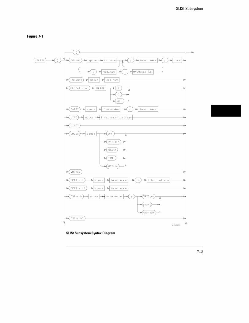
Figure 7-1
SLISt Subsystem Syntax Diagram
SLISt Subsystem
7–3
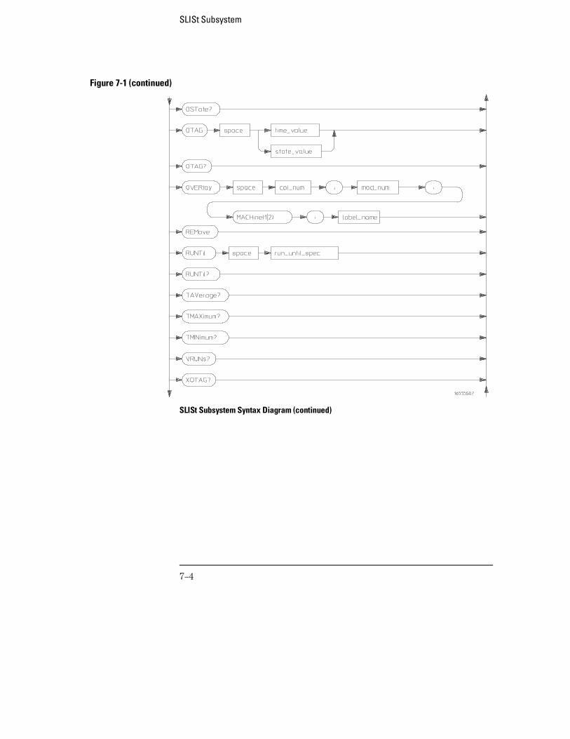
Figure 7-1 (continued)
SLISt Subsystem Syntax Diagram (continued)
SLISt Subsystem
7–4
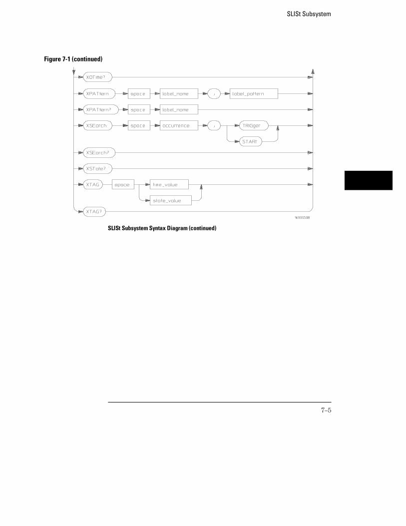
Figure 7-1 (continued)
SLISt Subsystem Syntax Diagram (continued)
SLISt Subsystem
7–5
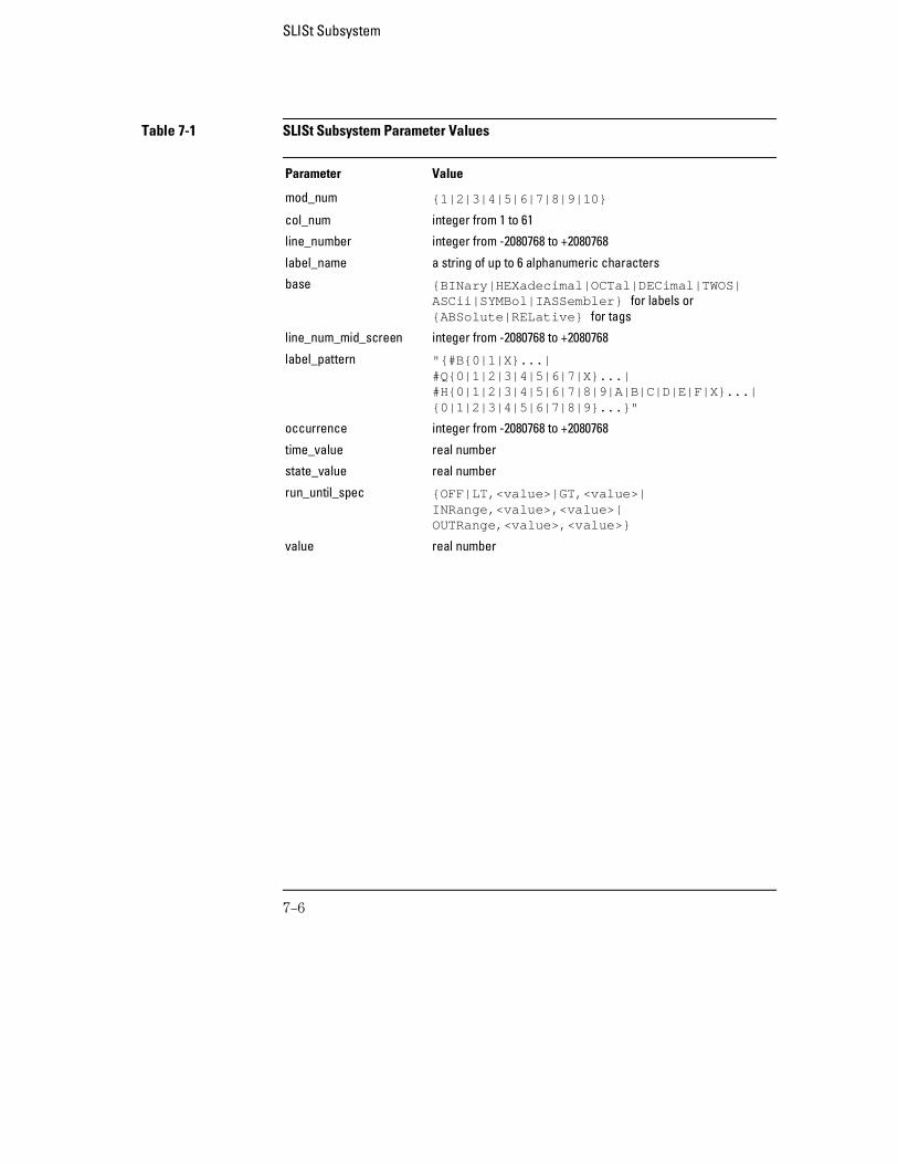
Table 7-1 SLISt Subsystem Parameter Values
Parameter Value
mod_num {1|2|3|4|5|6|7|8|9|10}
col_num integer from 1 to 61
line_number integer from -2080768 to +2080768
label_name a string of up to 6 alphanumeric characters
base {BINary|HEXadecimal|OCTal|DECimal|TWOS|ASCii|SYMBol|IASSembler} for labels or{ABSolute|RELative} for tags
line_num_mid_screen integer from -2080768 to +2080768
label_pattern "{#B{0|1|X}...|#Q{0|1|2|3|4|5|6|7|X}...|#H{0|1|2|3|4|5|6|7|8|9|A|B|C|D|E|F|X}...|{0|1|2|3|4|5|6|7|8|9}...}"
occurrence integer from -2080768 to +2080768
time_value real number
state_value real number
run_until_spec {OFF|LT,<value>|GT,<value>|INRange,<value>,<value>|OUTRange,<value>,<value>}
value real number
SLISt Subsystem
7–6
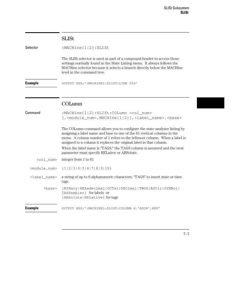
SLISt
Selector :MACHine{1|2}:SLISt
The SLISt selector is used as part of a compound header to access thosesettings normally found in the State Listing menu. It always follows theMACHine selector because it selects a branch directly below the MACHinelevel in the command tree.
Example OUTPUT XXX;":MACHINE1:SLIST:LINE 256"
COLumn
Command :MACHine{1|2}:SLISt:COLumn <col_num>[,<module_num>,MACHine{1|2}],<label_name>,<base>
The COLumn command allows you to configure the state analyzer listing byassigning a label name and base to one of the 61 vertical columns in themenu. A column number of 1 refers to the leftmost column. When a label isassigned to a column it replaces the original label in that column.
When the label name is "TAGS," the TAGS column is assumed and the nextparameter must specify RELative or ABSolute.
<col_num> integer from 1 to 61
<module_num> {1|2|3|4|5|6|7|8|9|10}
<label_name> a string of up to 6 alphanumeric characters; "TAGS" to insert state or timetags.
<base> {BINary|HEXadecimal|OCTal|DECimal|TWOS|ASCii|SYMBol|IASSembler} for labels or{ABSolute|RELative} for tags
Example OUTPUT XXX;":MACHINE1:SLIST:COLUMN 4,’ADDR’,HEX"
SLISt SubsystemSLISt
7–7
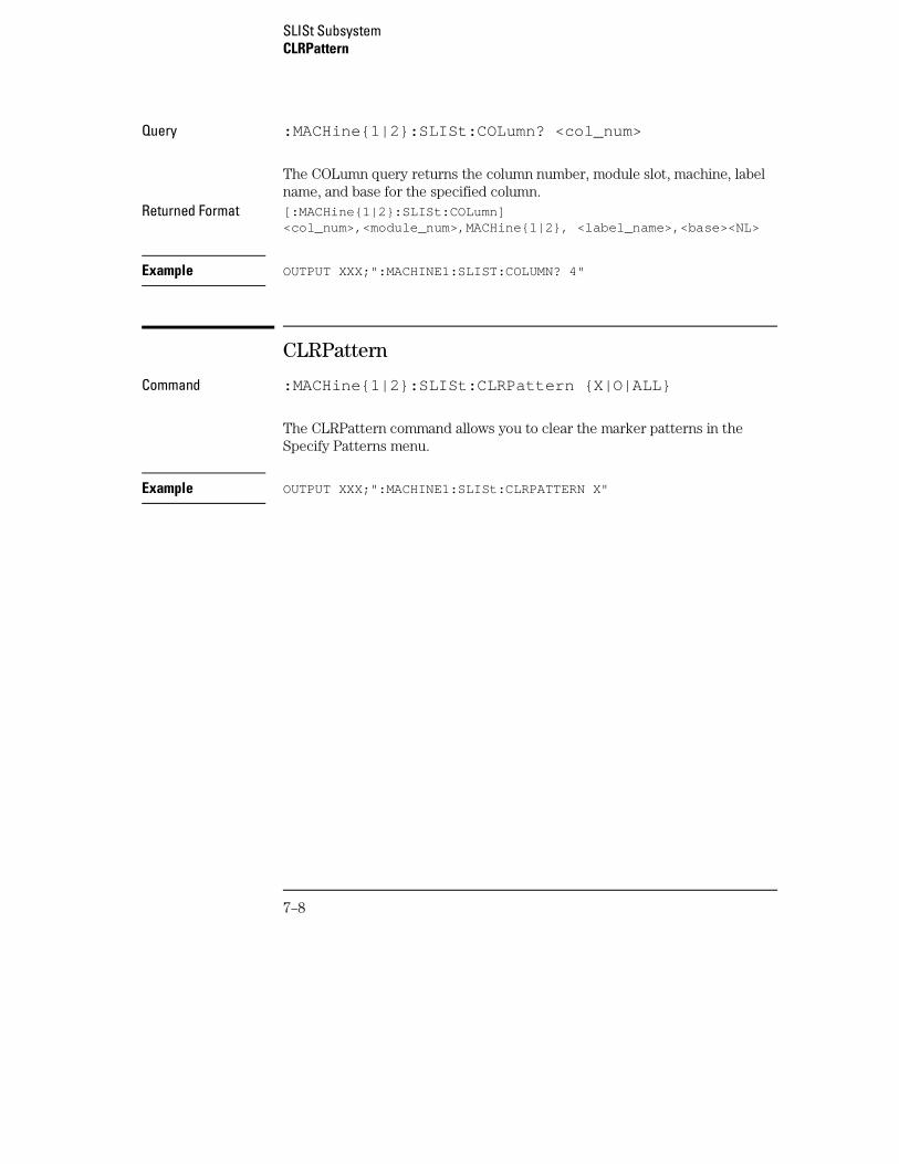
Query :MACHine{1|2}:SLISt:COLumn? <col_num>
The COLumn query returns the column number, module slot, machine, labelname, and base for the specified column.
Returned Format [:MACHine{1|2}:SLISt:COLumn]<col_num>,<module_num>,MACHine{1|2}, <label_name>,<base><NL>
Example OUTPUT XXX;":MACHINE1:SLIST:COLUMN? 4"
CLRPattern
Command :MACHine{1|2}:SLISt:CLRPattern {X|O|ALL}
The CLRPattern command allows you to clear the marker patterns in theSpecify Patterns menu.
Example OUTPUT XXX;":MACHINE1:SLISt:CLRPATTERN X"
SLISt SubsystemCLRPattern
7–8
DATA
Query :MACHine{1|2}:SLISt:DATA? <line_number>,<label_name>
The DATA query returns the value at a specified line number for a givenlabel. The format will be the same as the one shown in the listing display.
Returned Format [:MACHine{1|2}:SLISt:DATA] <line_number>,<label_name>, <pattern_string><NL>
<line_number> integer from -2080768 to +2080768
<label_name> string of up to 6 alphanumeric characters
<pattern_string>
"{#B{0|1|X} . . . |#Q{0|1|2|3|4|5|6|7|X} . . . |#H{0|1|2|3|4|5|6|7|8|9|A|B|C|D|E|F|X} . . . |{0|1|2|3|4|5|6|7|8|9} . . . }"
Example OUTPUT XXX;":MACHINE1:SLIST:DATA? 512, ’RAS’"
LINE
Command :MACHine{1|2}:SLISt:LINE <line_num_mid_screen>
The LINE command allows you to scroll the state analyzer listing vertically.The command specifies the state line number relative to the trigger. Theanalyzer highlights the specified line at the center of the screen.
<line_num_mid_screen>
integer from -2080768 to +2080768
Example OUTPUT XXX;":MACHINE1:SLIST:LINE 0"
SLISt SubsystemDATA
7–9
Query :MACHine{1|2}:SLISt:LINE?
The LINE query returns the line number for the state currently in the box atthe center of the screen.
Returned Format [:MACHine{1|2}:SLISt:LINE] <line_num_mid_screen><NL>
Example OUTPUT XXX;":MACHINE1:SLIST:LINE?"
MMODe
Command :MACHine{1|2}:SLISt:MMODe <marker_mode>
The MMODe command (Marker Mode) selects the mode controlling themarker movement and the display of marker readouts. When PATTern isselected, the markers will be placed on patterns. When STATe is selectedand state tagging is on, the markers move on qualified states countedbetween normally stored states. When TIME is selected and time tagging isenabled, the markers move on time between stored states. When MSTats isselected and time tagging is on, the markers are placed on patterns, but thereadouts will be time statistics.
<marker_mode> {OFF|PATTern|STATe|TIME|MSTats}
Example OUTPUT XXX;":MACHINE1:SLIST:MMODE TIME"
SLISt SubsystemMMODe
7–10
Query :MACHine{1|2}:SLISt:MMODe?
The MMODe query returns the current marker mode selected.Returned Format [:MACHine{1|2}:SLISt:MMODe] <marker_mode><NL>
Example OUTPUT XXX;":MACHINE1:SLIST:MMODE?"
OPATtern
Command :MACHine{1|2}:SLISt:OPATtern<label_name>,<label_pattern>
The OPATtern command allows you to construct a pattern recognizer termfor the O marker which is then used with the OSEarch criteria when movingthe marker on patterns. Because this command deals with only one label at atime, a complete specification could require several invocations.
When the value of a pattern is expressed in binary, it represents the bitvalues for the label inside the pattern recognizer term. In whatever base isused, the value must be between 0 and 232 − 1, since a label may not havemore than 32 bits. Because the <label_pattern> parameter may containdon’t cares, it is handled as a string of characters rather than a number.
<label_name> string of up to 6 alphanumeric characters
<label_pattern> "{#B{0|1|X} . . . |#Q{0|1|2|3|4|5|6|7|X} . . . |#H{0|1|2|3|4|5|6|7|8|9|A|B|C|D|E|F|X} . . . |{0|1|2|3|4|5|6|7|8|9} . . . }"
Example OUTPUT XXX;":MACHINE1:SLIST:OPATTERN ’DATA’,’255’ "OUTPUT XXX;":MACHINE2:SLIST:OPATTERN ’ABC’,’#BXXXX1101’ "
SLISt SubsystemOPATtern
7–11

Query :MACHine{1|2}:SLISt:OPATtern? <label_name>
The OPATtern query returns the pattern specification for a given label name.Returned Format [:MACHine{1|2}:SLISt:OPATtern]
<label_name>,<label_pattern><NL>
Example OUTPUT XXX;":MACHINE1:SLIST:OPATTERN? ’A’"
OSEarch
Command :MACHine{1|2}:SLISt:OSEarch <occurrence>,<origin>
The OSEarch command defines the search criteria for the O marker, which isthen used with associated OPATtern recognizer specification when movingthe markers on patterns. The origin parameter tells the marker to begin asearch with the trigger, the start of data, or with the X marker. The actualoccurrence the marker searches for is determined by the occurrenceparameter of the OSEarch recognizer specification, relative to the origin. Anoccurrence of 0 places the marker on the selected origin. With a negativeoccurrence, the marker searches before the origin. With a positiveoccurrence, the marker searches after the origin.
<occurrence> integer from -2080768 to +2080768
<origin> {TRIGger|STARt|XMARker}
Example OUTPUT XXX;":MACHINE1:SLIST:OSEARCH +10,TRIGGER"
SLISt SubsystemOSEarch
7–12
Query :MACHine{1|2}:SLISt:OSEarch?
The OSEarch query returns the search criteria for the O marker. Returned Format [:MACHine{1|2}:SLISt:OSEarch] <occurrence>,<origin><NL>
Example OUTPUT XXX;":MACHINE1:SLIST:OSEARCH?"
OSTate
Query :MACHine{1|2}:SLISt:OSTate?
The OSTate query returns the line number in the listing where the O markerresides. If data is not valid , the query returns 2147483647.
Returned Format [:MACHine{1|2}:SLISt:OSTate] <state_num><NL>
<state_num> integer from -2080768 to +2080768 or 2147483647
Example OUTPUT XXX;":MACHINE1:SLIST:OSTATE?"
SLISt SubsystemOSTate
7–13
OTAG
Command :MACHine{1|2}:SLISt:OTAG{<time_value>|<state_value>}
The OTAG command specifies the tag value on which the O marker should beplaced. The tag value is time when time tagging is on, or states when statetagging is on. If the data is not valid tagged data, no action is performed.
<time_value> real number
<state_value> real number
Example :OUTPUT XXX;":MACHINE1:SLIST:OTAG 40.0E −6"
Query :MACHine{1|2}:SLISt:OTAG?
The OTAG query returns the O marker position in time when time tagging ison or in states when state tagging is on, regardless of whether the markerwas positioned in time or through a pattern search. If data is not valid, thequery returns 9.9E37 for time tagging, or returns 2147483647 for statetagging.
Returned Format [:MACHine{1|2}:SLISt:OTAG] {<time_value>|<state_value>}<NL>
Example OUTPUT XXX;":MACHINE1:SLIST:OTAG?"
SLISt SubsystemOTAG
7–14
OVERlay
Command :MACHine{1|2}:SLISt:OVERlay <col_num>,<module_num>,MACHine{1|2},<label_name>
The OVERlay command allows you to add time-correlated labels from othermodules or machines to the state listing. The added labels are interleavedwith the column specified. The column must already contain a label.
<col_num> integer from 1 to 61
<Module_num> {1|2|3|4|5|6|7|8|9|10}
<label_name> a string of up to 6 alphanumeric characters
Example OUTPUT XXX;":MACHINE1:SLIST:OVERlay,25,5,MACHINE2,’DATA’"
REMove
Command :MACHine{1|2}:SLISt:REMove
The REMove command removes all labels, except the leftmost label, fromthe listing menu.
Example OUTPUT XXX;":MACHINE1:SLIST:REMOVE"
SLISt SubsystemOVERlay
7–15
RUNTil
Command :MACHine{1|2}:SLISt:RUNTil <run_until_spec>
The RUNTil (run until) command allows you to define a stop condition whenthe trace mode is repetitive. Specifying OFF causes the analyzer to makeruns until either the display’s STOP field is touched or the STOP command isissued.
There are four conditions based on the time between the X and O markers.Using this difference in the condition is effective only when time tags havebeen turned on (see the TAG command in the STRace subsystem). Thesefour conditions are as follows:
• The difference is less than (LT) some value.
• The difference is greater than (GT) some value.
• The difference is inside some range (INRange).
• The difference is outside some range (OUTRange).
End points for the INRange and OUTRange should be at least 8 ns apart sincethis is the minimum time resolution of the time tag counter.
<run_until_spec>
{OFF|LT,<value>|GT,<value>|INRange,<value>,<value>|OUTRange,<value>,<value>}
<value> real number from −9E9 to +9E9
Example OUTPUT XXX;":MACHINE1:SLIST:RUNTIL GT,800.0E −6"
Query :MACHine{1|2}:SLISt:RUNTil?
The RUNTil query returns the current stop criteria.Returned Format [:MACHine{1|2}:SLISt:RUNTil] <run_until_spec><NL>
Example OUTPUT XXX;":MACHINE1:SLIST:RUNTIL?"
SLISt SubsystemRUNTil
7–16
TAVerage
Query :MACHine{1|2}:SLISt:TAVerage?
The TAVerage query returns the value of the average time between the Xand O markers. If the number of valid runs is zero, the query returns 9.9E37.Valid runs are those where the pattern search for both the X and O markerswas successful, resulting in valid time measurements.
Returned Format [:MACHine{1|2}:SLISt:TAVerage] <time_value><NL>
<time_value> real number
Example OUTPUT XXX;":MACHINE1:SLIST:TAVERAGE?"
TMAXimum
Query :MACHine{1|2}:SLISt:TMAXimum?
The TMAXimum query returns the value of the maximum time between the Xand O markers. If data is not valid, the query returns 9.9E37.
Returned Format [:MACHine{1|2}:SLISt:TMAXimum] <time_value><NL>
<time_value> real number
Example OUTPUT XXX;":MACHINE1:SLIST:TMAXIMUM?"
SLISt SubsystemTAVerage
7–17
TMINimum
Query :MACHine{1|2}:SLISt:TMINimum?
The TMINimum query returns the value of the minimum time between the Xand O markers. If data is not valid, the query returns 9.9E37.
Returned Format [:MACHine{1|2}:SLISt:TMINimum] <time_value><NL>
<time_value> real number
Example OUTPUT XXX;":MACHINE1:SLIST:TMINIMUM?"
VRUNs
Query :MACHine{1|2}:SLISt:VRUNs?
The VRUNs query returns the number of valid runs and total number of runsmade. Valid runs are those where the pattern search for both the X and Omarkers was successful, resulting in valid time measurements.
Returned Format [:MACHine{1|2}:SLISt:VRUNs] <valid_runs>,<total_runs><NL>
<valid_runs> zero or positive integer
<total_runs> zero or positive integer
Example OUTPUT XXX;":MACHINE1:SLIST:VRUNS?"
SLISt SubsystemTMINimum
7–18
XOTag
Query :MACHine{1|2}:SLISt:XOTag?
The XOTag query returns the time from the X to O markers when the markermode is time, or number of states from the X to O markers when the markermode is state. If there is no data in the time mode the query returns 9.9E37.If there is no data in the state mode, the query returns 2147483647.
Returned Format [:MACHine{1|2}:SLISt:XOTag] {<XO_time>|<XO_states>}<NL>
<XO_time> real number
<XO_states> integer
Example OUTPUT XXX;":MACHINE1:SLIST:XOTAG?"
XOTime
Query :MACHine{1|2}:SLISt:XOTime?
The XOTime query returns the time from the X to O markers when themarker mode is time, or number of states from the X to O markers when themarker mode is state. If there is no data in the time mode the query returns9.9E37. If there is no data in the state mode, the query returns 2147483647.
Returned Format [:MACHine{1|2}:SLISt:XOTime] {<XO_time>|<XO_states>}<NL>
<XO_time> real number
<XO_states> integer
Example OUTPUT XXX;":MACHINE1:SLIST:XOTIME?"
SLISt SubsystemXOTag
7–19
XPATtern
Command :MACHine{1|2}:SLISt:XPATtern<label_name>,<label_pattern>
The XPATtern command allows you to construct a pattern recognizer termfor the X marker which is then used with the XSEarch criteria when movingthe marker on patterns. Since this command deals with only one label at atime, a complete specification could require several invocations.
When the value of a pattern is expressed in binary, it represents the bitvalues for the label inside the pattern recognizer term. In whatever base isused, the value must be between 0 and 232 − 1, since a label may not havemore than 32 bits. Because the <label_pattern> parameter may containdon’t cares, it is handled as a string of characters rather than a number.
<label_name> string of up to 6 alphanumeric characters
<label_pattern> "{#B{0|1|X} . . . |#Q{0|1|2|3|4|5|6|7|X} . . . |#H{0|1|2|3|4|5|6|7|8|9|A|B|C|D|E|F|X} . . . |{0|1|2|3|4|5|6|7|8|9} . . . }"
Examples OUTPUT XXX;":MACHINE1:SLIST:XPATTERN ’DATA’,’255’ "OUTPUT XXX;":MACHINE1:SLIST:XPATTERN ’ABC’,’#BXXXX1101’ "
Query :MACHine{1|2}:SLISt:XPATtern? <label_name>
The XPATtern query returns the pattern specification for a given label name.Returned Format [:MACHine{1|2}:SLISt:XPATtern]
<label_name>,<label_pattern><NL>
Example OUTPUT XXX;":MACHINE1:SLIST:XPATTERN? ’A’"
SLISt SubsystemXPATtern
7–20
XSEarch
Command :MACHine{1|2}:SLISt:XSEarch <occurrence>,<origin>
The XSEarch command defines the search criteria for the X marker, which isthen with associated XPATtern recognizer specification when moving themarkers on patterns. The origin parameter tells the marker to begin a searchfrom the trigger or from the start of data. The occurrence parameterdetermines which occurrence of the XPATtern recognizer specification,relative to the origin, the marker actually searches for. An occurrence of 0places a marker on the selected origin.
<occurrence> integer from -2080768 to +2080768
<origin> {TRIGger|STARt}
Example OUTPUT XXX;":MACHINE1:SLIST:XSEARCH +10,TRIGGER"
Query :MACHine{1|2}:SLISt:XSEarch?
The XSEarch query returns the search criteria for the X marker. Returned Format [:MACHine{1|2}:SLISt:XSEarch] <occurrence>,<origin><NL>
Example OUTPUT XXX;":MACHINE1:SLIST:XSEARCH?"
SLISt SubsystemXSEarch
7–21
XSTate
Query :MACHine{1|2}:SLISt:XSTate?
The XSTate query returns the line number in the listing where the X markerresides. If data is not valid, the query returns 2147483647.
Returned Format [:MACHine{1|2}:SLISt:XSTate] <state_num><NL>
<state_num> integer from -2080768 to +2080768 or 2147483647
Example OUTPUT XXX;":MACHINE1:SLIST:XSTATE?"
XTAG
Command :MACHine{1|2}:SLISt:XTAG{<time_value>|<state_value>}
The XTAG command specifies the tag value on which the X marker should beplaced. The tag value is time when time tagging is on, and states when statetagging is on. If the data is not valid tagged data, no action is performed.
<time_value> real number
<state_value> integer
Example OUTPUT XXX;":MACHINE1:SLIST:XTAG 40.0E −6"
SLISt SubsystemXSTate
7–22
Query :MACHine{1|2}:SLISt:XTAG?
The XTAG query returns the X marker position in time when time tagging ison or in states when state tagging is on, regardless of whether the markerwas positioned in time or through a pattern search. If data is not valid taggeddata, the query returns 9.9E37 for time tagging, or returns 2147483647 forstate tagging.
Returned Format [:MACHine{1|2}:SLISt:XTAG] {<time_value>|<state_value>}<NL>
Example OUTPUT XXX;":MACHINE1:SLIST:XTAG?"
SLISt SubsystemXTAG
7–23

7–24
8
SWAVeform Subsystem
Introduction
The commands in the State Waveform subsystem allow you toconfigure the display so that you can view state data as waveforms. Upto 96 channels, identified by label name and bit number, can bedisplayed at a time. The 12 commands in this subsystem areanalogous to their counterparts in the Timing Waveform subsystem.In this subsystem the X axis is restricted to representing only samples(states), regardless of whether time tagging is on or off. As a result,the only commands which can be used for scaling are DELay andRANge.
The way to manipulate the X and O markers on the Waveform displayis through the State Listing (SLISt) subsystem. Using the markercommands from the SLISt subsystem will affect the markers on theWaveform display.
The commands in the SWAVeform subsystem are:
• ACCumulate
• ACQuisition
• CENter
• CLRPattern
• CLRStat
• DELay
• INSert
• MLENgth
• RANGe
• REMove
• TAKenbranch
• TPOSition
8–2
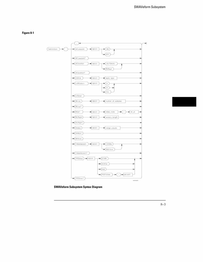
Figure 8-1
SWAVeform Subsystem Syntax Diagram
SWAVeform Subsystem
8–3
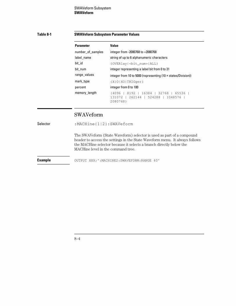
Table 8-1 SWAVeform Subsystem Parameter Values
Parameter Value
number_of_samples integer from -2080768 to +2080768
label_name string of up to 6 alphanumeric characters
bit_id {OVERlay|<bit_num>|ALL}
bit_num integer representing a label bit from 0 to 31
range_values integer from 10 to 5000 (representing (10 × states/Division))
mark_type {X|O|XO|TRIGger}
percent integer from 0 to 100
memory_length {4096 | 8192 | 16384 | 32768 | 65536 |131072 | 262144 | 524288 | 1048576 |2080768}
SWAVeform
Selector :MACHine{1|2}:SWAVeform
The SWAVeform (State Waveform) selector is used as part of a compoundheader to access the settings in the State Waveform menu. It always followsthe MACHine selector because it selects a branch directly below theMACHine level in the command tree.
Example OUTPUT XXX;":MACHINE2:SWAVEFORM:RANGE 40"
SWAVeform SubsystemSWAVeform
8–4
ACCumulate
Command :MACHine{1|2}:SWAVeform:ACCumulate{{ON|1}|{OFF|0}}
The ACCumulate command allows you to control whether the waveformdisplay gets erased between individual runs or whether subsequentwaveforms are allowed to be displayed over the previous waveforms.
Example OUTPUT XXX;":MACHINE1:SWAVEFORM:ACCUMULATE ON"
Query MACHine{1|2}:SWAVeform:ACCumulate?
The ACCumulate query returns the current setting. The query always showsthe setting as the characters, "0" (off) or "1" (on).
Returned Format [MACHine{1|2}:SWAVeform:ACCumulate] {0|1}<NL>
Example OUTPUT XXX;":MACHINE1:SWAVEFORM:ACCUMULATE?"
ACQuisition
Command :MACHine{1|2}:SWAVeform:ACQuisition {AUTOmatic|MANual}
The ACQuisition command allows you to specify the acquisition mode for thestate analyzer. The acquisition modes are automatic and manual.
Example OUTPUT XXX;":MACHINE2:SWAVEFORM:ACQUISITION AUTOMATIC"
SWAVeform SubsystemACCumulate
8–5
Query MACHine{1|2}:SWAVeform:ACQuisition?
The ACQuisition query returns the current acquisition mode.Returned Format [MACHine{1|2}:SWAVeform:ACQuisition] {AUTOmatic|MANual}<NL>
Example OUTPUT XXX;":MACHINE2:SWAVEFORM:ACQUISITION?"
CENTer
Command :MACHine{1|2}:SWAVeform:CENTer <marker_type>
The CENTer command allows you to center the waveform display about thespecified markers. The markers are placed on the waveform in the SLIStsubsystem.
<marker_type> {X|O|XO|TRIGger}
Example OUTPUT XXX;":MACHINE1:SWAVEFORM:CENTER X"
CLRPattern
Command :MACHine{1|2}:SWAVeform:CLRPattern {X|O|ALL}
The CLRPattern command allows you to clear the marker patterns in theselected Specify Patterns menu.
Example OUTPUT XXX;":MACHINE1:SWAVEFORM:CLRPATTERN"
SWAVeform SubsystemCENTer
8–6
CLRStat
Command :MACHine{1|2}:SWAVeform:CLRStat
The CLRStat command allows you to clear the waveform statistics withouthaving to stop and restart the acquisition.
Example OUTPUT XXX;":MACHINE1:SWAVEFORM:CLRSTAT"
DELay
Command :MACHine{1|2}:SWAVeform:DELay <number_of_samples>
The DELay command allows you to specify the number of samples betweenthe State trigger and the horizontal center of the screen for the waveformdisplay.
<number_of_samples>
integer from -2080768 to +2080768
Example OUTPUT XXX;":MACHINE2:SWAVEFORM:DELAY 127"
Query MACHine{1|2}:SWAVeform:DELay?
The DELay query returns the current sample offset value.Returned Format [MACHine{1|2}:SWAVeform:DELay] <number_of_samples><NL>
Example OUTPUT XXX;":MACHINE1:SWAVEFORM:DELAY?"
SWAVeform SubsystemCLRStat
8–7
INSert
Command MACHine{1|2}:SWAVeform:INSert <label_name>,<bit_id>
The INSert command allows you to add waveforms to the state waveformdisplay. Waveforms are added from top to bottom on the screen. When 96waveforms are present, inserting additional waveforms replaces the lastwaveform. Bit numbers are zero-based, so a label with 8 bits is referenced asbits 0 through 7. Specifying OVERlay causes a composite waveform displayof all bits or channels for the specified label.
<label_name> string of up to 6 alphanumeric characters
<bit_id> {OVERlay | <bit_num> | ALL}
<bit_num> integer representing a label bit from 0 to 31
Example OUTPUT XXX;":MACHINE1:SWAVEFORM:INSERT ’WAVE’, 19"OUTPUT XXX;":MACHINE1:SWAVEFORM:INSERT ’ABC’, OVERLAY"OUTPUT XXX;":MACH1:SWAV:INSERT ’POD1’, #B1001"
MLENgth
Command :MACHine{1|2}:SWAVeform:MLENgth <memory_length>
The MLENgth command allows you to specify the analyzer memory depth.Valid memory depths range from 4096 states (or samples) through themaximum system memory depth minus 8192 states. Memory depth isaffected by acquisition mode. If the <memory_length> value sent with thecommand is not a legal value, the closest legal setting will be used.
<memory_length> {4096 | 8192 | 16384 | 32768 | 65536 | 131072 | 262144 | 524288 | 1048576 | 2080768}
SWAVeform SubsystemINSert
8–8
Example OUTPUT XXX;":MACHINE1:SWAVEFORM:MLENGTH 262144"
Query :MACHine{1|2}:SWAVeform:MLENgth?
The MLENgth query returns the current analyzer memory depth selection.Returned Format [:MACHine{1|2}:SWAVeform:MLENgth] <memory_length><NL>
Example OUTPUT XXX;":MACHINE1:SWAVEFORM:MLENGTH?"
RANGe
Command MACHine{1|2}:SWAVeform:RANGe <number_of_samples>
The RANGe command allows you to specify the number of samples acrossthe screen on the State Waveform display. It is equivalent to ten times thestates per division setting (states/Div) on the front panel. A number between10 and 5000 may be entered.
<number_of_samples>
integer from 10 to 5000
Example OUTPUT XXX;":MACHINE2:SWAVEFORM:RANGE 80"
Query MACHine{1|2}:SWAVeform:RANGe?
The RANGe query returns the current range value.Returned Format [MACHine{1|2}:SWAVeform:RANGe] <number_of_samples><NL>
Example OUTPUT XXX;":MACHINE2:SWAVEFORM:RANGE?"
SWAVeform SubsystemRANGe
8–9
REMove
Command :MACHine{1|2}:SWAVeform:REMove
The REMove command clears the waveform display before building a newdisplay.
Example OUTPUT XXX;":MACHINE1:SWAVEFORM:REMOVE"
TAKenbranch
Command MACHine{1|2}:SWAVeform:TAKenbranch {STORe|NOSTore}
The TAKenbranch command allows you to control whether the states thatcause branching are stored or not stored. This command is only availablewhen the acquisition mode is set to manual.
Example OUTPUT XXX;":MACHINE2:SWAVEFORM:TAKENBRANCH STORE"
Query MACHine{1|2}:SWAVeform:TAKenbranch?
The TAKenbranch query returns the current setting.Returned Format [MACHine{1|2}:SWAVeform:TAKenbranch] {STORe|NOSTore}<NL>
Example OUTPUT XXX;":MACHINE2:SWAVEFORM:TAKENBRANCH?"
SWAVeform SubsystemREMove
8–10
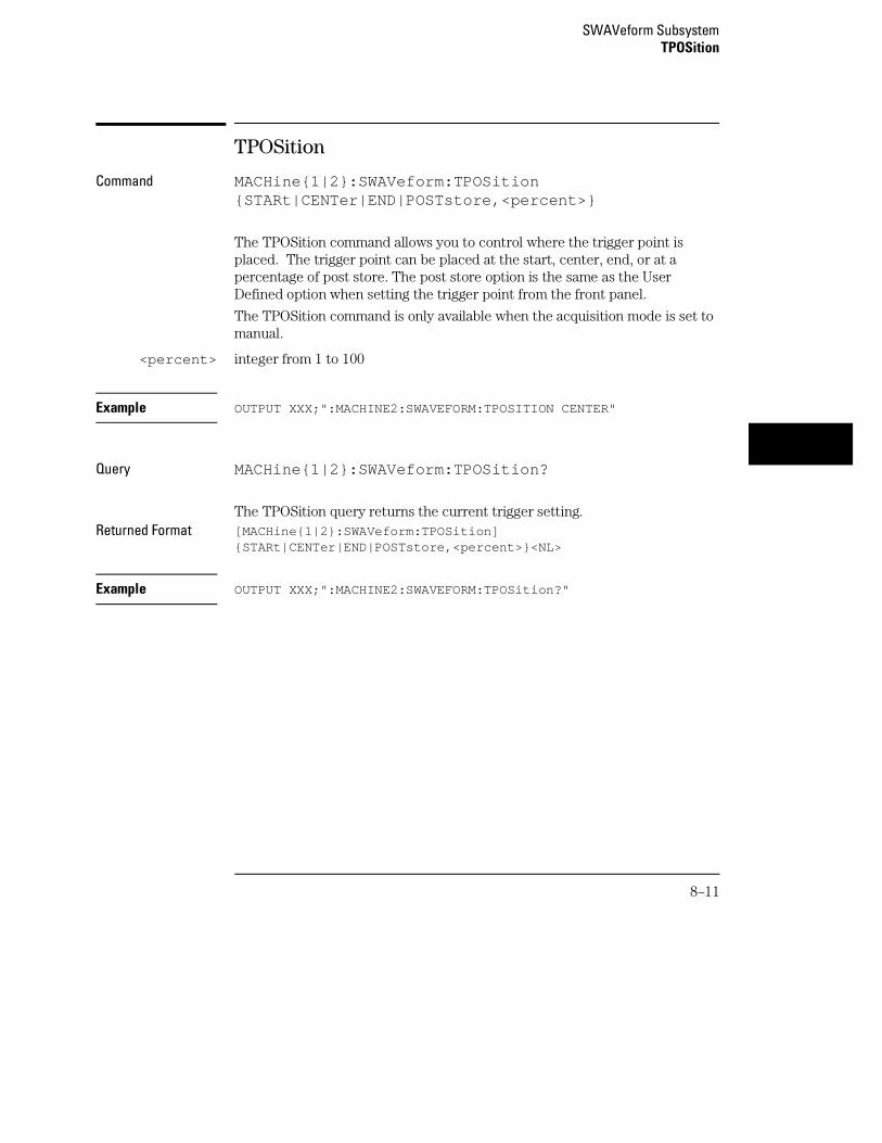
TPOSition
Command MACHine{1|2}:SWAVeform:TPOSition{STARt|CENTer|END|POSTstore,<percent>}
The TPOSition command allows you to control where the trigger point isplaced. The trigger point can be placed at the start, center, end, or at apercentage of post store. The post store option is the same as the UserDefined option when setting the trigger point from the front panel.
The TPOSition command is only available when the acquisition mode is set tomanual.
<percent> integer from 1 to 100
Example OUTPUT XXX;":MACHINE2:SWAVEFORM:TPOSITION CENTER"
Query MACHine{1|2}:SWAVeform:TPOSition?
The TPOSition query returns the current trigger setting.Returned Format [MACHine{1|2}:SWAVeform:TPOSition]
{STARt|CENTer|END|POSTstore,<percent>}<NL>
Example OUTPUT XXX;":MACHINE2:SWAVEFORM:TPOSition?"
SWAVeform SubsystemTPOSition
8–11

8–12
9
SCHart Subsystem
Introduction
The State Chart subsystem provides the commands necessary forprogramming the 16557D’s Chart display. The commands allow youto build charts of label activity, using data normally found in theListing display. The chart’s Y axis is used to show data values for thelabel of your choice. The X axis can be used in two different ways. Inone, the X axis represents states (shown as rows in the State Listingdisplay). In the other, the X axis represents the data values foranother label.
When states are plotted along the X axis, X and O markers areavailable. Because the State Chart display is simply an alternative wayof looking at the data in the State Listing, the X and O markers aremanipulated through the SLISt subsystem. Because the programmingcommands do not force the menus to switch, you can position themarkers in the SLISt subsystem and see the effects in the State Chartdisplay.
The commands in the SCHart subsystem are:
• ACCumulate
• CENTer
• HAXis
• VAXis
9–2
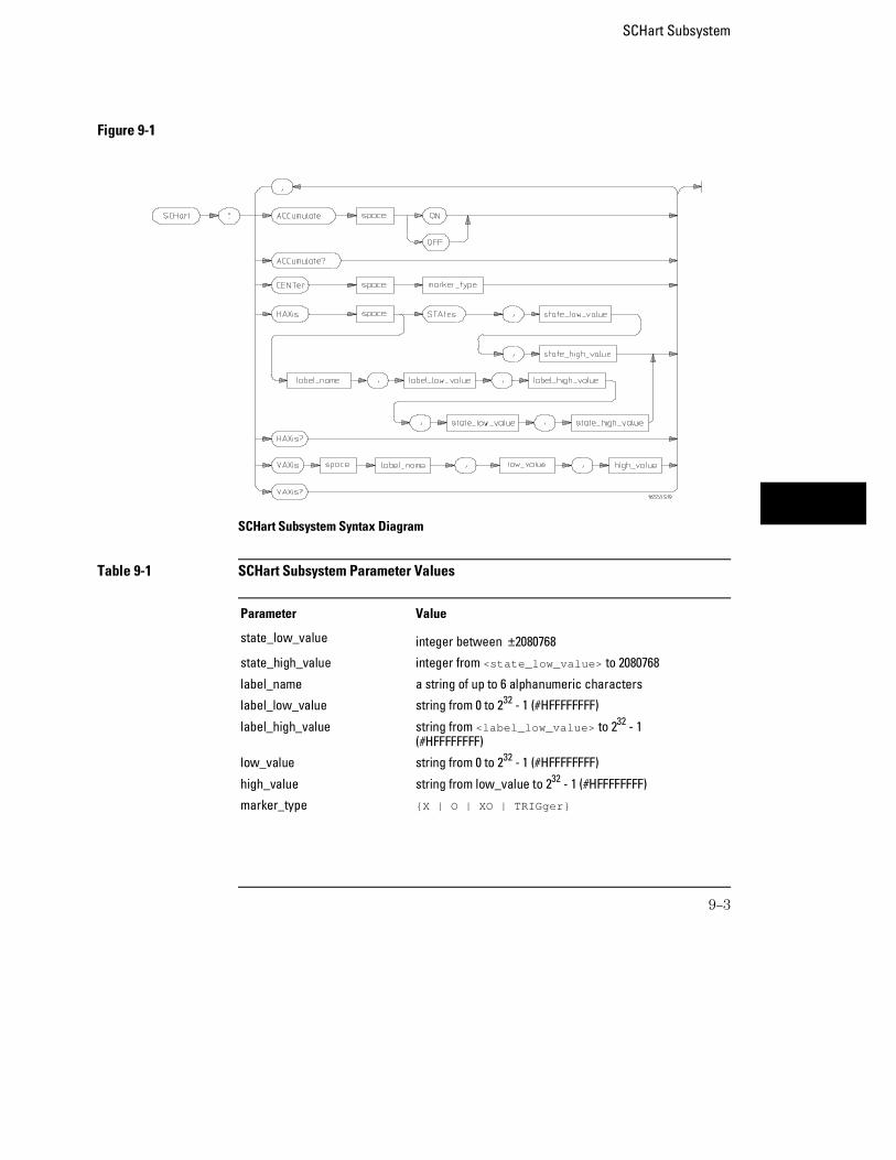
Figure 9-1
SCHart Subsystem Syntax Diagram
Table 9-1 SCHart Subsystem Parameter Values
Parameter Value
state_low_value integer between ±2080768
state_high_value integer from <state_low_value> to 2080768
label_name a string of up to 6 alphanumeric characters
label_low_value string from 0 to 232 - 1 (#HFFFFFFFF)
label_high_value string from <label_low_value> to 232 - 1(#HFFFFFFFF)
low_value string from 0 to 232 - 1 (#HFFFFFFFF)
high_value string from low_value to 232 - 1 (#HFFFFFFFF)
marker_type {X | O | XO | TRIGger}
SCHart Subsystem
9–3
SCHart
Selector :MACHine{1|2}:SCHart
The SCHart selector is used as part of a compound header to access thesettings found in the State Chart menu. It always follows the MACHineselector because it selects a branch below the MACHine level in thecommand tree.
Example OUTPUT XXX;":MACHINE1:SCHART:VAXIS ’A’, ’0’, ’9’"
ACCumulate
Command MACHine{1|2}:SCHart:ACCumulate {{ON|1} | {OFF|0}}
The ACCumulate command controls whether the chart display gets erasedbetween each individual run or whether subsequent waveforms are displayedover the previous waveforms.
Example OUTPUT XXX;":MACHINE1:SCHART:ACCUMULATE OFF"
Query MACHine{1|2}:SCHart:ACCumulate?
The ACCumulate query returns the current setting. The query always showsthe setting as the character "0" (off) or "1" (on).
Returned Format [:MACHine{1|2}:SCHart:ACCumulate] {0|1}<NL>
Example OUTPUT XXX;":MACHINE1:SCHART:ACCUMULATE?"
SCHart SubsystemSCHart
9–4
CENTer
Command MACHine{1|2}:SCHart:CENTer <marker_type>
The CENTer command centers the chart display about the specified markers.The markers are placed in the SLISt subsystem.
<marker_type> {X | O | XO | TRIGger}
Example OUTPUT XXX;":MACHINE1:SCHART:CENTER XO"
HAXis
Command MACHine{1|2}:SCHart:HAXis{STAtes,<state_low_value>,<state_high_value>|<label_name>,<label_low_value>,<label_high_value>, <state_low_value>,<state_high_value>}
The HAXis command allows you to select whether states or a label’s valueswill be plotted on the horizontal axis of the chart. The axis is scaled byspecifying the high and low values. The shortform for STATES is STA. Thisis an intentional deviation from the normal truncation rule.
<state_low_value>
integer from –2080768 to +2080768
<state_high_value>
integer from <state_low_value> to +2080768
<label_name> a string of up to 6 alphanumeric characters
<label_low_value>
string from 0 to 232−1 (#HFFFFFFFF)
<label_high_value>
string from <label_low_value> to 232–1 (#HFFFFFFFF)
SCHart SubsystemCENTer
9–5
Example OUTPUT XXX;":MACHINE1:SCHART:HAXIS STATES, −100, 100"
OUTPUT XXX;":MACHINE1:SCHART:HAXIS ’READ’, ’ −511’, ’511’, 0,300"
Query MACHine{1|2}:SCHart:HAXis?
The HAXis query returns the current horizontal axis label and scaling.Returned Format [:MACHine{1|2}:SCHart:HAXis] {STAtes,<state_low_value>,
<state_high_value>|<label_name>,<label_low_value>,<label_high_value><state_low_value>,<state_high_value>}
Example OUTPUT XXX;":MACHINE1:SCHART:HAXIS?"
VAXis
Command MACHine{1|2}:SCHart:VAXis<label_name>,<low_value>,<high_value>
The VAXis command allows you to choose which label will be plotted on thevertical axis of the chart and scales the vertical axis by specifying the highvalue and low value.
<label_name> a string of up to 6 alphanumeric characters
<low_value> string from 0 to 232–1 (#HFFFFFFFF)
<high_value> string from <low_value> to 232–1 (#HFFFFFFFF)
Example OUTPUT XXX;":MACHINE2:SCHART:VAXIS ’SUM1’, ’0’, ’99’"OUTPUT XXX;":MACHINE1:SCHART:VAXIS ’BUS’, ’#H00FF’, ’#H0500’"
SCHart SubsystemVAXis
9–6

Query MACHine{1|2}:SCHart:VAXis?
The VAXis query returns the current vertical axis label and scaling.Returned Format [:MACHine{1|2}:SCHart:VAXis] <label_name>,<low_value>,
<high_value><NL>
Example OUTPUT XXX;":MACHINE1:SCHART:VAXIS?"
SCHart SubsystemVAXis
9–7

9–8
10
COMPare Subsystem
Introduction
Commands in the state COMPare subsystem provide the ability to do abit-by-bit comparison between the acquired state data listing and acompare data image. The commands are:
• CLEar
• CMASk
• COPY
• DATA
• FIND
• LINE
• MENU
• RANGe
• RUNTil
• SET
10–2
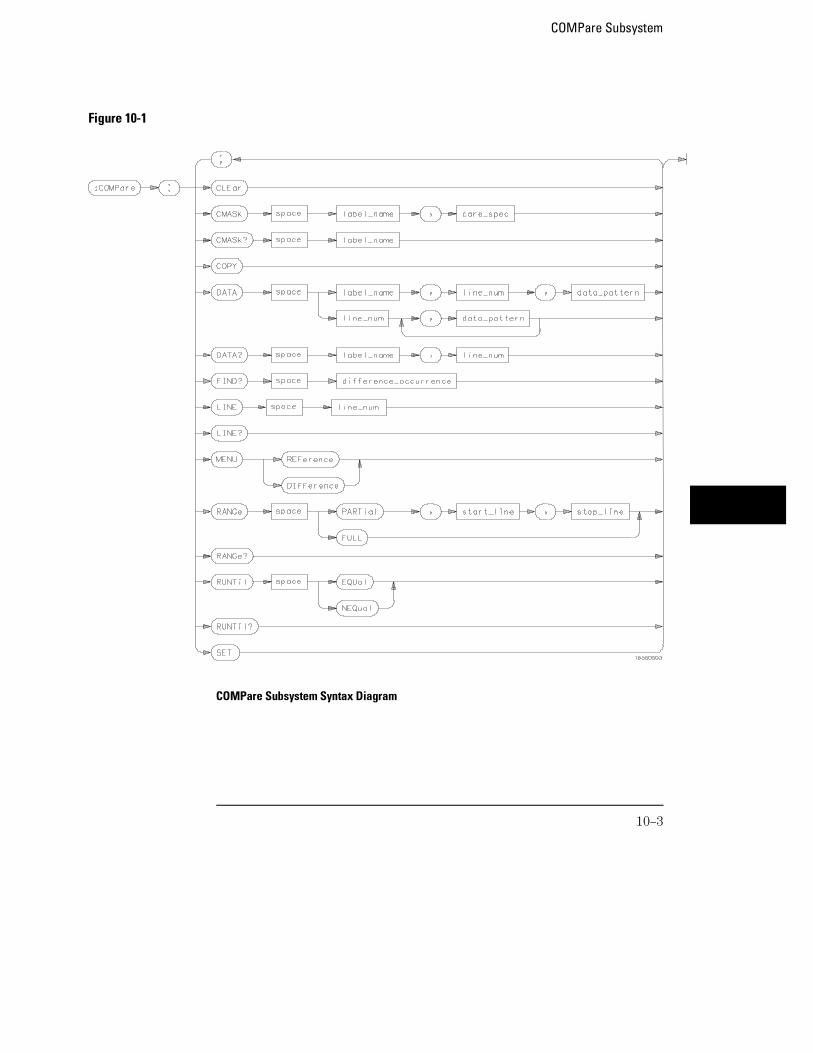
COMPare Subsystem Syntax Diagram
Figure 10-1
COMPare Subsystem
10–3

Table 10-1 COMPare Subsystem Parameter Values
Parameter Value
label_name string of up to 6 characters
care_spec string of characters "{*|.}..."
* care
. don’t care
line_num integer from -507903 to +507903
data_pattern "{#B{0|1|X} ... |#Q{0|1|2|3|4|5|6|7|X} ... |#H{0|1|2|3|4|5|6|7|8|9|A|B|C|D|E|F|X} ... |
{0|1|2|3|4|5|6|7|8|9} ... }"
difference_occurrence integer from 1 to 507903
start_line integer from -507903 to +507903
stop_line integer from <start_line> to +507903
COMPare
Selector :MACHine{1|2}:COMPare
The COMPare selector is used as part of a compound header to access thesettings found in the Compare menu. It always follows the MACHine selectorbecause it selects a branch directly below the MACHine level in the commandtree.
Example OUTPUT XXX;":MACHINE1:COMPARE:FIND? 819"
COMPare SubsystemCOMPare
10–4
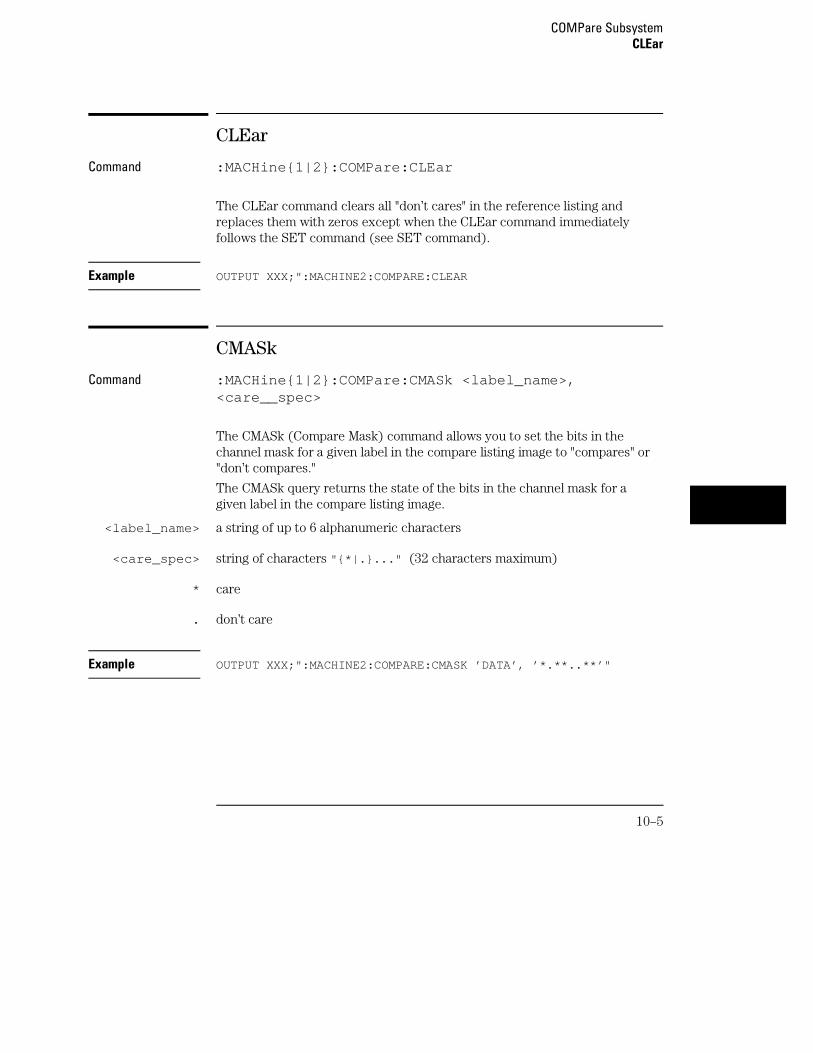
CLEar
Command :MACHine{1|2}:COMPare:CLEar
The CLEar command clears all "don’t cares" in the reference listing andreplaces them with zeros except when the CLEar command immediatelyfollows the SET command (see SET command).
Example OUTPUT XXX;":MACHINE2:COMPARE:CLEAR
CMASk
Command :MACHine{1|2}:COMPare:CMASk <label_name>,<care__spec>
The CMASk (Compare Mask) command allows you to set the bits in thechannel mask for a given label in the compare listing image to "compares" or"don’t compares."
The CMASk query returns the state of the bits in the channel mask for agiven label in the compare listing image.
<label_name> a string of up to 6 alphanumeric characters
<care_spec> string of characters "{*|.}..." (32 characters maximum)
* care
. don’t care
Example OUTPUT XXX;":MACHINE2:COMPARE:CMASK ’DATA’, ’*.**..**’"
COMPare SubsystemCLEar
10–5
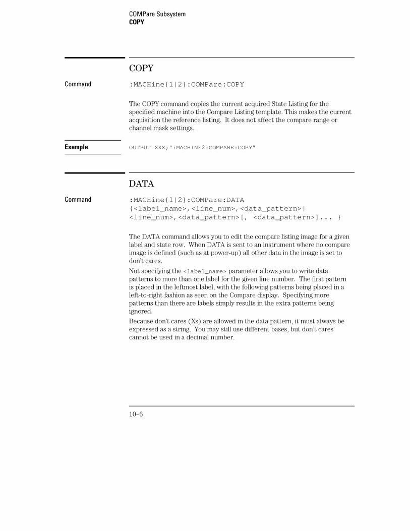
COPY
Command :MACHine{1|2}:COMPare:COPY
The COPY command copies the current acquired State Listing for thespecified machine into the Compare Listing template. This makes the currentacquisition the reference listing. It does not affect the compare range orchannel mask settings.
Example OUTPUT XXX;":MACHINE2:COMPARE:COPY"
DATA
Command :MACHine{1|2}:COMPare:DATA{<label_name>,<line_num>,<data_pattern>|<line_num>,<data_pattern>[, <data_pattern>]... }
The DATA command allows you to edit the compare listing image for a givenlabel and state row. When DATA is sent to an instrument where no compareimage is defined (such as at power-up) all other data in the image is set todon’t cares.
Not specifying the <label_name> parameter allows you to write datapatterns to more than one label for the given line number. The first patternis placed in the leftmost label, with the following patterns being placed in aleft-to-right fashion as seen on the Compare display. Specifying morepatterns than there are labels simply results in the extra patterns beingignored.
Because don’t cares (Xs) are allowed in the data pattern, it must always beexpressed as a string. You may still use different bases, but don’t carescannot be used in a decimal number.
COMPare SubsystemCOPY
10–6
<label_name> a string of up to 6 alphanumeric characters
<line_num> integer from –507903 to +507903
<data_pattern> "{#B{0|1|X} . . . |#Q{0|1|2|3|4|5|6|7|X} . . . |#H{0|1|2|3|4|5|6|7|8|9|A|B|C|D|E|F|X} . . . |{0|1|2|3|4|5|6|7|8|9} . . . }"
Example OUTPUT XXX;":MACHINE2:COMPARE:DATA ’CLOCK’, 42, ’#B011X101X’"OUTPUT XXX;":MACHINE2:COMPARE:DATA ’OUT3’, 0, ’#HFF40’"OUTPUT XXX;":MACH1:COMP:DATA 129,’#BXX00’,’#B1101’,’#B10XX’"
OUTPUT XXX;":MACH1:COMP:DATA −511,’4’,’64’,’16’,’256’,’8’,’6’"
Query :MACHine{1|2}:COMPare:DATA? <label_name>,<line_num>
The DATA query returns the value of the compare listing image for a givenlabel and state row.
Returned Format [:MACHine{1|2}:COMPare:DATA] <label_name>,<line_num>,<data_pattern><NL>
Example
10 DIM Label$[6], Response$[80]15 PRINT "This program shows the values for a signal’s Compare listing"20 INPUT "Enter signal label: ", Label$25 OUTPUT XXX;":SYSTEM:HEADER OFF" !Turn headers off (from responses)30 OUTPUT XXX;":MACHINE2:COMPARE:RANGE?"35 ENTER XXX; First, Last !Read in the range’s end-points40 PRINT "LINE #", "VALUE of "; Label$45 FOR State = First TO Last !Print compare value for each state50 OUTPUT XXX;":MACH2:COMPARE:DATA? ’" Label$ "’," VAL$(State)55 ENTER XXX; Response$60 PRINT State, Response$65 NEXT State70 END
COMPare SubsystemDATA
10–7
FIND
Query :MACHine{1|2}:COMPare:FIND? <diff_occurrence>
The FIND query is used to get the line number of a specified differenceoccurrence (first, second, third, etc.) within the current compare range, asdictated by the RANGe command. A difference is counted for each linewhere at least one of the current labels has a discrepancy between itsacquired state data listing (difference listing) and its compare data image(reference listing).
Invoking the FIND query updates both the Listing and Compare displays sothat the line number returned is in the center of the screen.
If <diff_occurrence> is greater than the number of differences, the queryreturns the last difference and the associated line number.
Returned Format [:MACHine{1|2}:COMPare:FIND] <difference_occurrence>,<line_number><NL>
<diff_occurrence>
integer from 1 to 507903.
<line_number> integer from –507903 to +507903.
Example OUTPUT XXX;":MACHINE2:COMPARE:FIND? 26"
COMPare SubsystemFIND
10–8
LINE
Command :MACHine{1|2}:COMPare:LINE <line_num>
The LINE command allows you to center the compare listing display about aspecified line number. The Listing menu also changes so that the specifiedline is displayed midscreen.
<line_num> integer from –507903 to +507903.
Example OUTPUT XXX;":MACHINE2:COMPARE:LINE –511"
Query :MACHine{1|2}:COMPare:LINE?
The LINE query returns the current line number specified.Returned Format [:MACHine{1|2}:COMPare:LINE] <line_num>}<NL>
Example OUTPUT XXX;":MACHINE4:COMPARE:LINE?"
MENU
Command :MACHine{1|2}:COMPare:MENU {REFerence|DIFFerence}
The MENU command allows you to display the reference or the differencelistings in the Compare menu.
Example OUTPUT XXX;":MACHINE2:COMPARE:MENU REFERENCE"
COMPare SubsystemLINE
10–9
RANGe
Command :MACHine{1|2}:COMPare:RANGe {FULL |PARTial,<start_line>,<stop_line>}
The RANGe command allows you to define the boundaries for thecomparison. The range entered must be a subset of the lines in theacquisition memory.
<start_line> integer from –507904 to +507904
<stop_line> integer from <start_line> to +507904
Example OUTPUT XXX;":MACHINE1:COMPARE:RANGE PARTIAL, –511, 512"OUTPUT XXX;":MACHINE2:COMPARE:RANGE FULL"
Query :MACHine{1|2}:COMPare:RANGe?
The RANGe query returns the current boundaries for the comparison.Returned Format [:MACHine{1|2}:COMPare:RANGe] {FULL|PARTial,<start_line>,
<stop_line>}<NL>
Example 10 DIM String$[100]20 OUTPUT 707;":SELECT 2"30 OUTPUT 707;":MACHINE1:COMPARE:RANGE?"40 ENTER 707;String$50 PRINT "RANGE IS ";String$60 END
COMPare SubsystemRANGe
10–10
RUNTil
Command :MACHine{1|2}:COMPare:RUNTil {OFF | LT,<value> |GT,<value> | INRange,<value>,<value> |OUTRange,<value>,<value> | EQUal | NEQual}
The RUNTil (run until) command allows you to define a stop condition whenthe trace mode is repetitive. Specifying OFF causes the analyzer to makeruns until either the display’s STOP field is touched or the STOP command isissued.
There are four conditions based on the time between the X and O markers.Using this difference in the condition is effective only when time tags havebeen turned on (see the TAG command in the STRigger subsystem). Thesefour conditions are as follows:
• The difference is less than (LT) some value.
• The difference is greater than (GT) some value.
• The difference is inside some range (INRange).
• The difference is outside some range (OUTRange).
End points for the INRange and OUTRange should be at least 8 ns apart sincethis is the minimum time resolution of the time tag counter.
There are two conditions which are based on a comparison of the acquiredstate data and the reference listing. You can run until one of the followingconditions is true:
• Every channel of every label has the same value (EQUal).
• Any channel of any label has a different value (NEQual).
<value> real number from −9E9 to +9E9
Example OUTPUT XXX;":MACHINE2:COMPARE:RUNTIL EQUAL"
COMPare SubsystemRUNTil
10–11
Query :MACHine{1|2}:COMPare:RUNTil?
The RUNTil query returns the current stop criteria for the comparison whenrunning in repetitive trace mode.
Returned Format [:MACHine{1|2}:COMPare:RUNTil] {OFF| LT,<value>|GT,<value>|INRange,<value>,<value>|OUTRange,<value>,<value>|EQUal|NEQual}<NL>
Example OUTPUT XXX;":MACHINE2:COMPARE:RUNTIL?"
SET
Command :MACHine{1|2}:COMPare:SET
The SET command sets every state in the reference listing to "don’t cares." Ifyou send the SET command by mistake you can immediately send the CLEarcommand to restore the previous data. This is the only time the CLEarcommand will not replace "don’t cares" with zeros.
Example OUTPUT XXX;":MACHINE2:COMPARE:SET"
COMPare SubsystemSET
10–12
11
TFORmat Subsystem
Introduction
The TFORmat subsystem contains the commands available for theTiming Format menu in the 16557D logic analyzer module. Thesecommands are:
• ACQMode
• LABel
• REMove
• THReshold
11–2
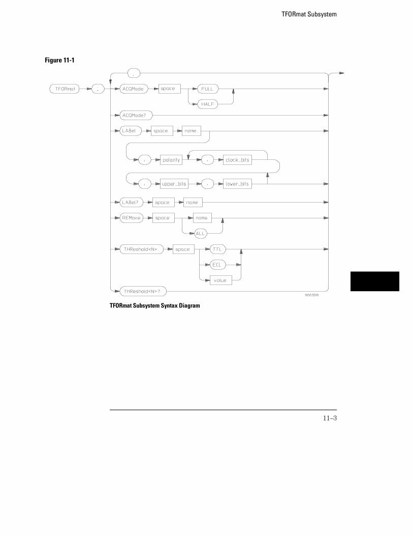
TFORmat Subsystem Syntax Diagram
Figure 11-1
TFORmat Subsystem
11–3
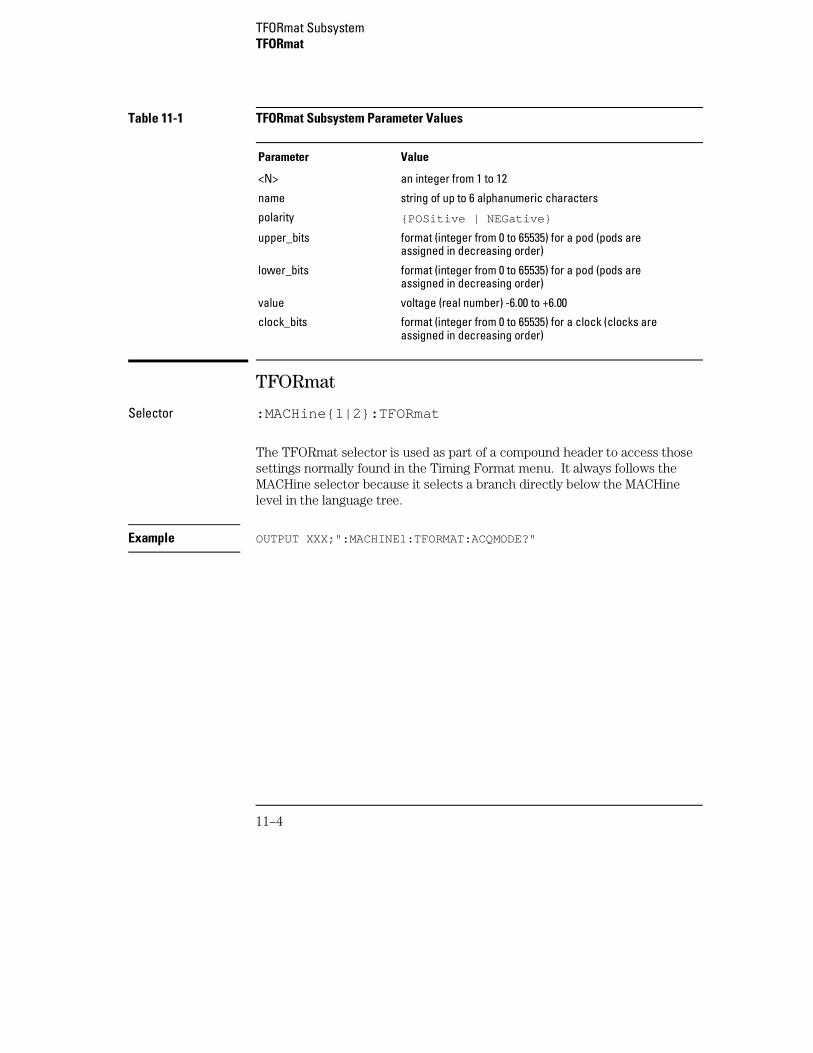
Table 11-1 TFORmat Subsystem Parameter Values
Parameter Value
<N> an integer from 1 to 12
name string of up to 6 alphanumeric characters
polarity {POSitive | NEGative}
upper_bits format (integer from 0 to 65535) for a pod (pods areassigned in decreasing order)
lower_bits format (integer from 0 to 65535) for a pod (pods areassigned in decreasing order)
value voltage (real number) -6.00 to +6.00
clock_bits format (integer from 0 to 65535) for a clock (clocks areassigned in decreasing order)
TFORmat
Selector :MACHine{1|2}:TFORmat
The TFORmat selector is used as part of a compound header to access thosesettings normally found in the Timing Format menu. It always follows theMACHine selector because it selects a branch directly below the MACHinelevel in the language tree.
Example OUTPUT XXX;":MACHINE1:TFORMAT:ACQMODE?"
TFORmat SubsystemTFORmat
11–4
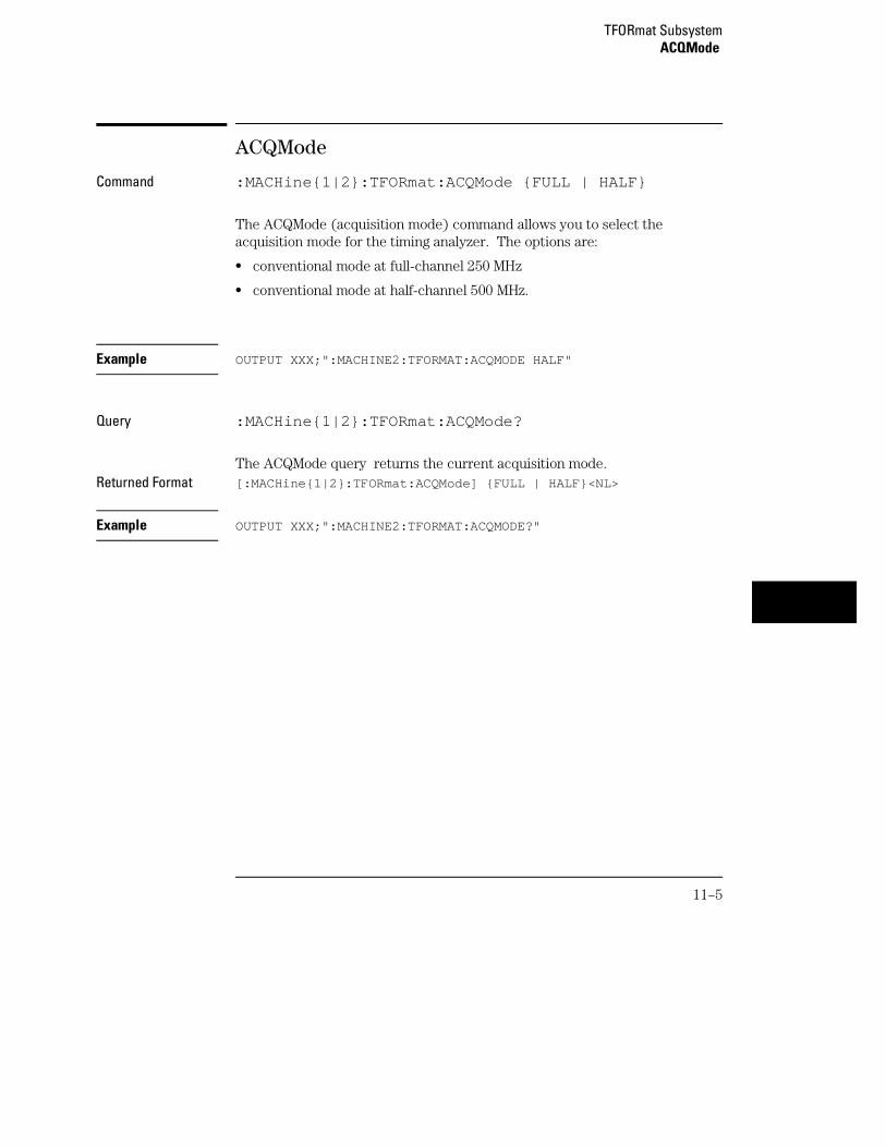
ACQMode
Command :MACHine{1|2}:TFORmat:ACQMode {FULL | HALF}
The ACQMode (acquisition mode) command allows you to select theacquisition mode for the timing analyzer. The options are:
• conventional mode at full-channel 250 MHz
• conventional mode at half-channel 500 MHz.
Example OUTPUT XXX;":MACHINE2:TFORMAT:ACQMODE HALF"
Query :MACHine{1|2}:TFORmat:ACQMode?
The ACQMode query returns the current acquisition mode.Returned Format [:MACHine{1|2}:TFORmat:ACQMode] {FULL | HALF}<NL>
Example OUTPUT XXX;":MACHINE2:TFORMAT:ACQMODE?"
TFORmat SubsystemACQMode
11–5
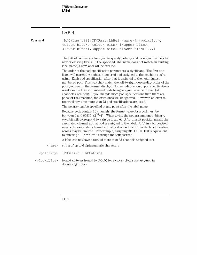
LABel
Command :MACHine{1|2}:TFORmat:LABel <name>[,<polarity>,<clock_bits>,[<clock_bits>,]<upper_bits>,<lower_bits>[,<upper_bits>,<lower_bits>]...]
The LABel command allows you to specify polarity and to assign channels tonew or existing labels. If the specified label name does not match an existinglabel name, a new label will be created.
The order of the pod-specification parameters is significant. The first onelisted will match the highest numbered pod assigned to the machine you’reusing. Each pod specification after that is assigned to the next highestnumbered pod. This way they match the left-to-right descending order of thepods you see on the Format display. Not including enough pod specificationsresults in the lowest numbered pods being assigned a value of zero (allchannels excluded). If you include more pod specifications than there arepods for that machine, the extra ones will be ignored. However, an error isreported any time more than 22 pod specifications are listed.
The polarity can be specified at any point after the label name.
Because pods contain 16 channels, the format value for a pod must bebetween 0 and 65535 (216−1). When giving the pod assignment in binary,each bit will correspond to a single channel. A "1" in a bit position means theassociated channel in that pod is assigned to the label. A "0" in a bit positionmeans the associated channel in that pod is excluded from the label. Leadingzeroes may be omitted. For example, assigning #B1111001100 is equivalentto entering "......****..**.." through the touchscreen.
A label can not have a total of more than 32 channels assigned to it.
<name> string of up to 6 alphanumeric characters
<polarity> {POSitive | NEGative}
<clock_bits> format (integer from 0 to 65535) for a clock (clocks are assigned indecreasing order)
TFORmat SubsystemLABel
11–6
<upper_bits> format (integer from 0 to 65535) for a pod (pods are assigned in decreasingorder)
<lower_bits> format (integer from 0 to 65535) for a pod (pods are assigned in decreasingorder)
Example OUTPUT XXX;":MACHINE2:TFORMAT:LABEL ’STAT’,POSITIVE,0,127,40312"OUTPUT XXX;":MACHINE2:TFORMAT:LABEL ’SIG 1’, #B11,#B0000000011111111,#B0000000000000000 "
Query :MACHine{1|2}:TFORmat:LABel? <name>
The LABel query returns the current specification for the selected (by name)label. If the label does not exist, nothing is returned. Numbers are alwaysreturned in decimal format.
Returned Format [:MACHine{1|2}:TFORmat:LABel] <name>,<polarity>[,<assignment>]...<NL>
<assignment> format (integer from 0 to 65535) for a pod (pods are assigned in decreasingorder)
Example OUTPUT XXX;":MACHINE2:TFORMAT:LABEL? ’DATA’"
REMove
Command :MACHine{1|2}:TFORmat:REMove {<name>|ALL}
The REMove command allows you to delete all labels or any one labelspecified by name for a given machine.
<name> string of up to 6 alphanumeric characters
Example OUTPUT XXX;":MACHINE1:TFORMAT:REMOVE ’A’"
TFORmat SubsystemREMove
11–7
THReshold
Command :MACHine{1|2}:TFORmat:THReshold<N>{TTL|ECL|<value>}
The THReshold command allows you to set the voltage threshold for a givenpod to ECL, TTL, or a specific voltage from −6.00 V to +6.00 V in 0.05 voltincrements.
<N> pod number (integer from 1 to 12)
<value> voltage (real number) −6.00 to +6.00
TTL default value of +1.6 V
ECL default value of −1.3 V
Example OUTPUT XXX;":MACHINE1:TFORMAT:THRESHOLD1 4.0"
Query :MACHine{1|2}:TFORmat:THReshold<N>?
The THReshold query returns the current threshold for a given pod.Returned Format [:MACHine{1|2}:TFORmat:THReshold<N>] <value><NL>
Example OUTPUT XXX;":MACHINE1:TFORMAT:THRESHOLD2?"
TFORmat SubsystemTHReshold
11–8

12
TTRigger (TTRace) Subsystem
Introduction
The TTRigger subsystem contains the commands available for theTiming Trigger menu in the 16557D logic analyzer module. TheTiming Trigger subsystem will also accept the TTRace selector asused in previous Agilent Technologies 16500-series logic analyzermodules to eliminate the need to rewrite programs containing TTRaceas the selector keyword. The TTRigger subsystem commands are:
• ACQuisition
• BRANch
• CLEar
• EDGE
• FIND
• MLENgth
• RANGe
• SEQuence
• SPERiod
• TCONtrol
• TERM
• TIMER
• TPOSition
12–2
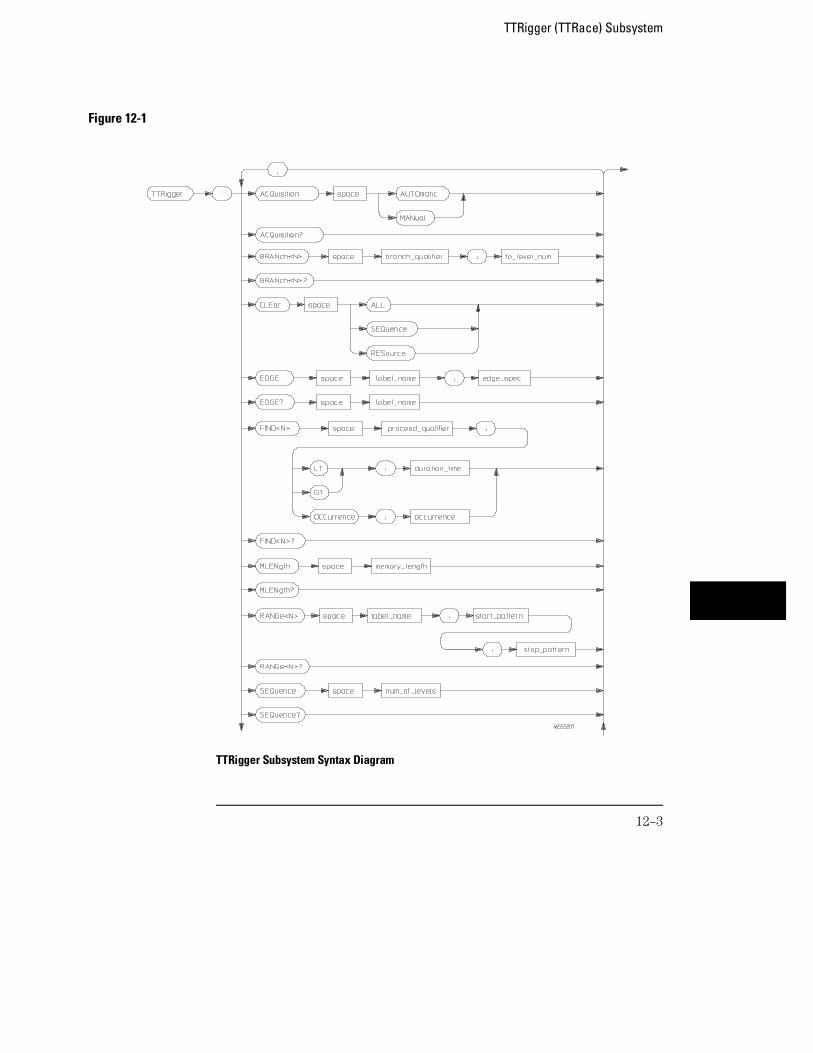
Figure 12-1
TTRigger Subsystem Syntax Diagram
TTRigger (TTRace) Subsystem
12–3
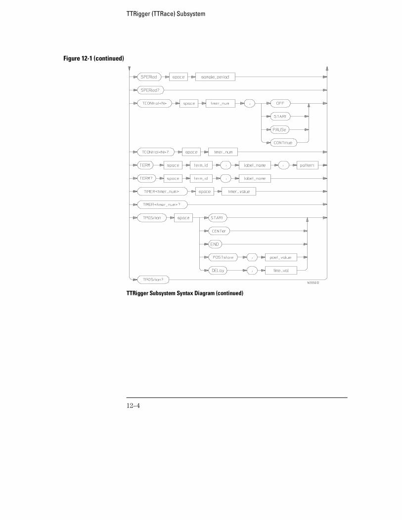
Figure 12-1 (continued)
TTRigger Subsystem Syntax Diagram (continued)
TTRigger (TTRace) Subsystem
12–4
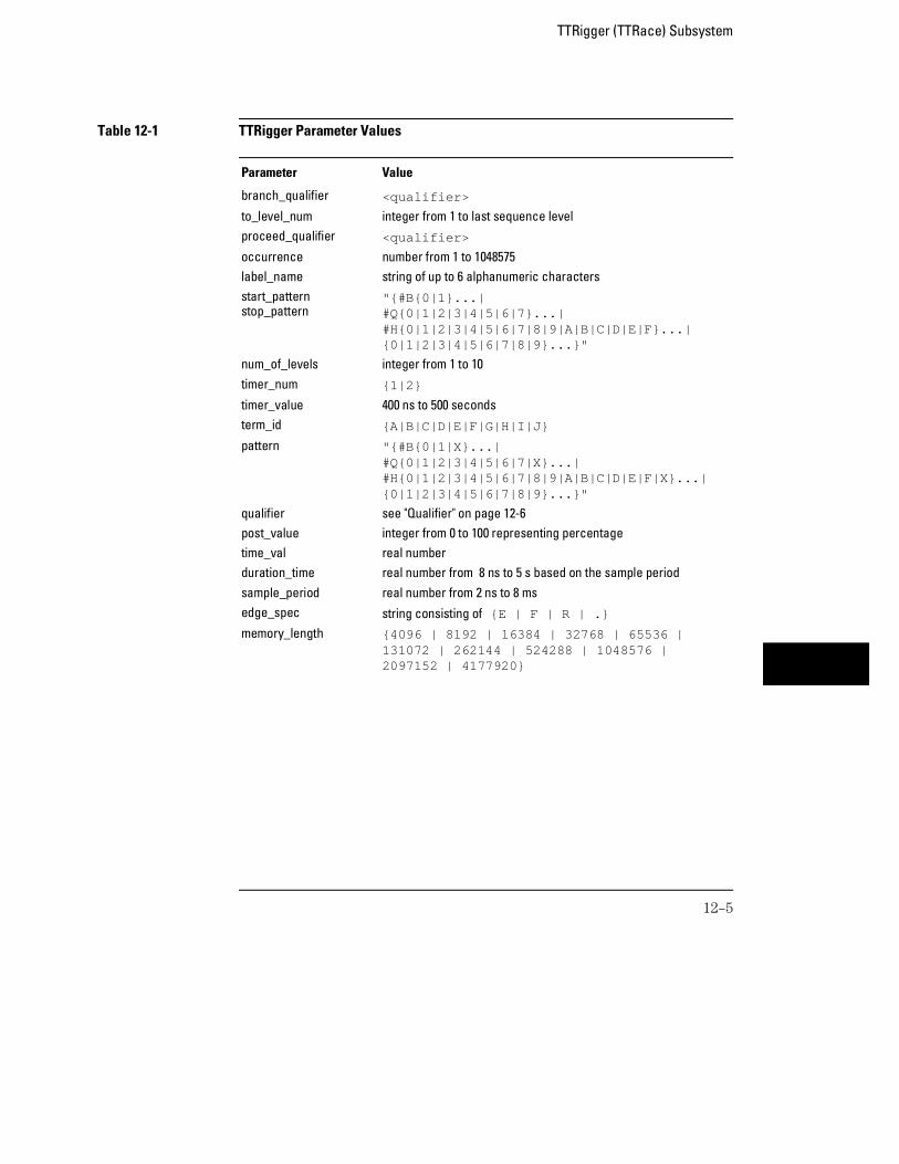
Table 12-1 TTRigger Parameter Values
Parameter Value
branch_qualifier <qualifier>
to_level_num integer from 1 to last sequence levelproceed_qualifier <qualifier>
occurrence number from 1 to 1048575 label_name string of up to 6 alphanumeric charactersstart_patternstop_pattern
"{#B{0|1}...|#Q{0|1|2|3|4|5|6|7}...|#H{0|1|2|3|4|5|6|7|8|9|A|B|C|D|E|F}...|{0|1|2|3|4|5|6|7|8|9}...}"
num_of_levels integer from 1 to 10timer_num {1|2}
timer_value 400 ns to 500 secondsterm_id {A|B|C|D|E|F|G|H|I|J}
pattern "{#B{0|1|X}...|#Q{0|1|2|3|4|5|6|7|X}...|#H{0|1|2|3|4|5|6|7|8|9|A|B|C|D|E|F|X}...|{0|1|2|3|4|5|6|7|8|9}...}"
qualifier see "Qualifier" on page 12-6post_value integer from 0 to 100 representing percentagetime_val real numberduration_time real number from 8 ns to 5 s based on the sample periodsample_period real number from 2 ns to 8 msedge_spec string consisting of {E | F | R | .}
memory_length {4096 | 8192 | 16384 | 32768 | 65536 |131072 | 262144 | 524288 | 1048576 |2097152 | 4177920}
TTRigger (TTRace) Subsystem
12–5
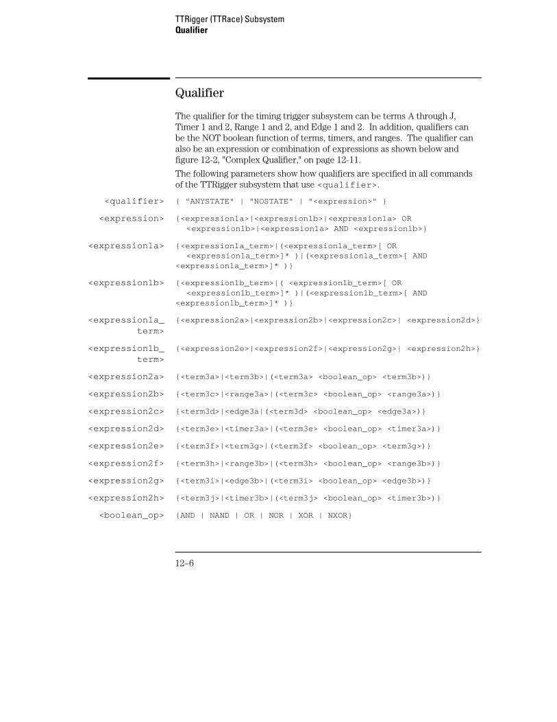
Qualifier
The qualifier for the timing trigger subsystem can be terms A through J,Timer 1 and 2, Range 1 and 2, and Edge 1 and 2. In addition, qualifiers canbe the NOT boolean function of terms, timers, and ranges. The qualifier canalso be an expression or combination of expressions as shown below andfigure 12-2, "Complex Qualifier," on page 12-11.
The following parameters show how qualifiers are specified in all commandsof the TTRigger subsystem that use <qualifier> .
<qualifier> { "ANYSTATE" | "NOSTATE" | "<expression>" }
<expression> {<expression1a>|<expression1b>|<expression1a> OR <expression1b>|<expression1a> AND <expression1b>}
<expression1a> {<expression1a_term>|(<expression1a_term>[ OR <expression1a_term>]* )|(<expression1a_term>[ AND<expression1a_term>]* )}
<expression1b> {<expression1b_term>|( <expression1b_term>[ OR <expression1b_term>]* )|(<expression1b_term>[ AND<expression1b_term>]* )}
<expression1a_term>
{<expression2a>|<expression2b>|<expression2c>| <expression2d>}
<expression1b_term>
{<expression2e>|<expression2f>|<expression2g>| <expression2h>}
<expression2a> {<term3a>|<term3b>|(<term3a> <boolean_op> <term3b>)}
<expression2b> {<term3c>|<range3a>|(<term3c> <boolean_op> <range3a>)}
<expression2c> {<term3d>|<edge3a|(<term3d> <boolean_op> <edge3a>)}
<expression2d> {<term3e>|<timer3a>|(<term3e> <boolean_op> <timer3a>)}
<expression2e> {<term3f>|<term3g>|(<term3f> <boolean_op> <term3g>)}
<expression2f> {<term3h>|<range3b>|(<term3h> <boolean_op> <range3b>)}
<expression2g> {<term3i>|<edge3b>|(<term3i> <boolean_op> <edge3b>)}
<expression2h> {<term3j>|<timer3b>|(<term3j> <boolean_op> <timer3b>)}
<boolean_op> {AND | NAND | OR | NOR | XOR | NXOR}
TTRigger (TTRace) SubsystemQualifier
12–6
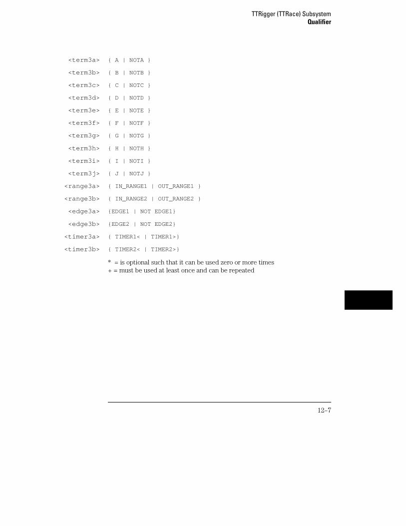
<term3a> { A | NOTA }
<term3b> { B | NOTB }
<term3c> { C | NOTC }
<term3d> { D | NOTD }
<term3e> { E | NOTE }
<term3f> { F | NOTF }
<term3g> { G | NOTG }
<term3h> { H | NOTH }
<term3i> { I | NOTI }
<term3j> { J | NOTJ }
<range3a> { IN_RANGE1 | OUT_RANGE1 }
<range3b> { IN_RANGE2 | OUT_RANGE2 }
<edge3a> {EDGE1 | NOT EDGE1}
<edge3b> {EDGE2 | NOT EDGE2}
<timer3a> { TIMER1< | TIMER1>}
<timer3b> { TIMER2< | TIMER2>}
* = is optional such that it can be used zero or more times+ = must be used at least once and can be repeated
TTRigger (TTRace) SubsystemQualifier
12–7
Qualifier Rules
The following rules apply to qualifiers:
• Qualifiers are quoted strings and, therefore, need quotes.
• Expressions are evaluated from left to right.
• Parentheses are used to change the order evaluation and, therefore, areoptional.
• An expression must map into the combination logic presented in thecombination pop-up menu within the TTRigger menu.
Examples ’A’’( A OR B )’’(( A OR B ) AND C )’’(( A OR B ) AND C AND IN_RANGE2 )’’(( A OR B ) AND ( C AND IN_RANGE1 ))’’IN_RANGE1 AND ( A OR B ) AND C’
TTRigger (TTRace)
Selector :MACHine{1|2}:TTRigger
The TTRigger (TTRace) (Timing Trigger) selector is used as a part of acompound header to access the settings found in the Timing Trigger menu.It always follows the MACHine selector because it selects a branch directlybelow the MACHine level in the command tree.
Example OUTPUT XXX;":MACHINE1:TTRIGGER:TAG TIME"
TTRigger (TTRace) SubsystemTTRigger (TTRace)
12–8
ACQuisition
Command :MACHine{1|2}:TTRigger:ACQuisition{AUTOmatic|MANual}
The ACQuisition command allows you to specify the acquisition mode for thetiming analyzer.
Example OUTPUT XXX;":MACHINE1:TTRIGGER:ACQUISITION AUTOMATIC"
Query :MACHine{1|2}:TTRigger:ACQuisition?
The ACQuisition query returns the current acquisition mode specified.Returned Format [:MACHine{1|2}:TTRigger:ACQuisition] {AUTOmatic|MANual}<NL>
Example OUTPUT XXX;":MACHINE1:TTRIGGER:ACQUISITION?"
BRANch
Command :MACHine{1|2}:TTRigger:BRANch<N><branch_qualifier>,<to_level_number>
The BRANch command defines the branch qualifier for a given sequencelevel. When this branch qualifier is matched, it will cause the sequencerto jump to the specified sequence level. BRANch functions like the "else on"branch of the front-panel sequence level.
The terms used by the branch qualifier (A through J) are defined by theTERM command. The meaning of IN_RANGE and OUT_RANGE isdetermined by the RANGe command. The edge terms are defined by theEDGE command.
TTRigger (TTRace) SubsystemACQuisition
12–9
Within the limitations shown by the syntax definitions, complex expressionsmay be formed using the AND and OR operators. Expressions are limited towhat you could manually enter through the Timing Trigger menu. Regardingparentheses, the syntax definitions on the next page show only the requiredones. Additional parentheses are allowed as long as the meaning of theexpression is not changed. Figure 12-2, on page 12-11, shows a complexexpression as seen in the Timing Trigger menu.
Example The following statements are all correct and have the same meaning. Noticethat the conventional rules for precedence are not followed. The expressionsare evaluated from left to right.OUTPUT XXX;":MACHINE1:TTRIGGER:BRANCH1 ’C AND D OR F OR G’, 1"OUTPUT XXX;":MACHINE1:TTRIGGER:BRANCH1 ’((C AND D) OR (F ORG))’, 1"OUTPUT XXX;":MACHINE1:TTRIGGER:BRANCH1 ’F OR (C AND D) ORG’,1"
<N> integer from 1 to <number_of_levels>
<to_level_number>
integer from 1 to <number_of_levels>
<number_of_levels>
integer from 1 to the number of existing sequence levels (maximum 10)
<branch_qualifier>
<qualifier> see "Qualifier" on page 12-6
Example OUTPUT XXX;":MACHINE1:TTRIGGER:BRANCH1 ’ANYSTATE’, 3"OUTPUT XXX;":MACHINE2:TTRIGGER:BRANCH2 ’A’, 7"OUTPUT XXX;":MACHINE1:TTRIGGER:BRANCH3 ’((A OR B) OR NOTG)’,1"
TTRigger (TTRace) SubsystemBRANch
12–10
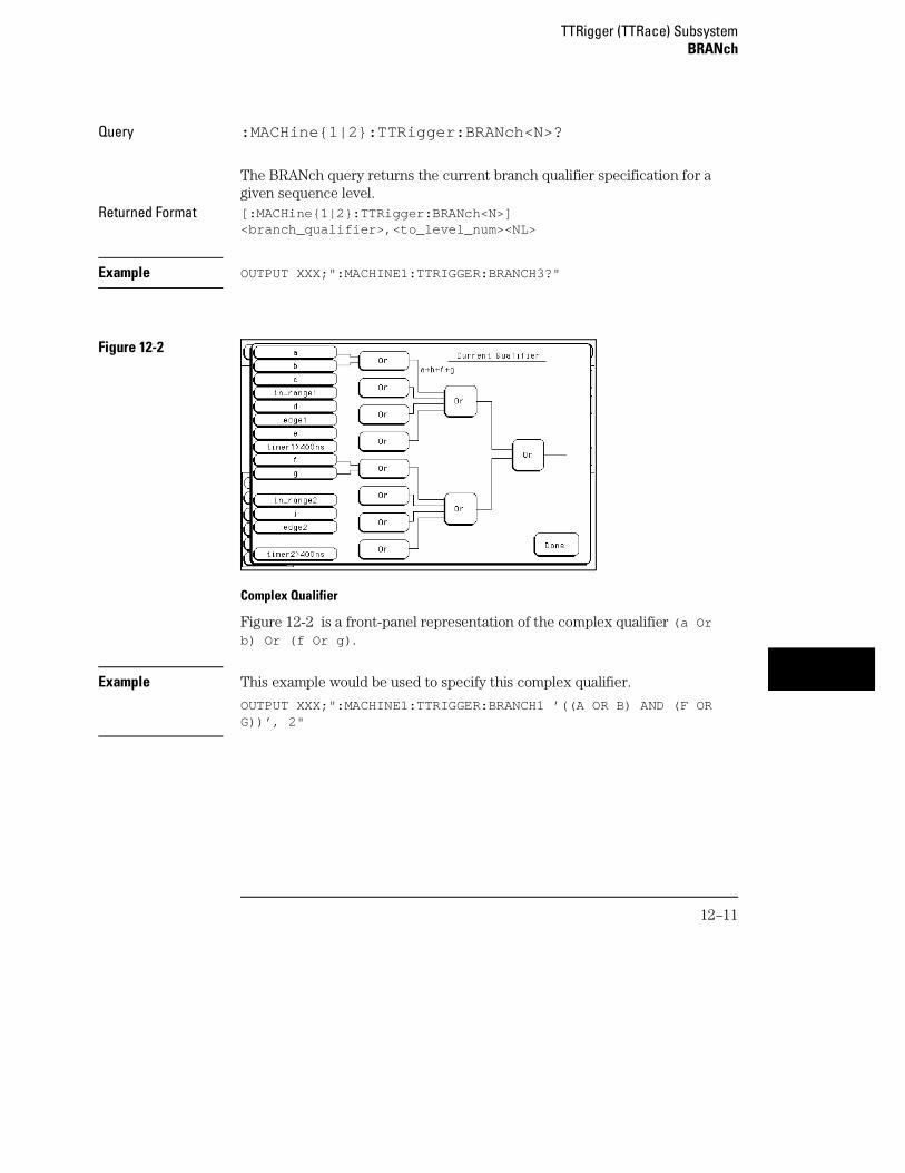
Query :MACHine{1|2}:TTRigger:BRANch<N>?
The BRANch query returns the current branch qualifier specification for agiven sequence level.
Returned Format [:MACHine{1|2}:TTRigger:BRANch<N>]<branch_qualifier>,<to_level_num><NL>
Example OUTPUT XXX;":MACHINE1:TTRIGGER:BRANCH3?"
Figure 12-2
Complex Qualifier
Figure 12-2 is a front-panel representation of the complex qualifier (a Orb) Or (f Or g) .
Example This example would be used to specify this complex qualifier.
OUTPUT XXX;":MACHINE1:TTRIGGER:BRANCH1 ’((A OR B) AND (F ORG))’, 2"
TTRigger (TTRace) SubsystemBRANch
12–11
Terms A through E, RANGE 1, EDGE1, and TIMER 1 must be grouped togetherand terms F through J, RANGE 2, EDGE2, and TIMER 2 must be groupedtogether. In the first level, terms from one group may not be mixed with termsfrom the other. For example, the expression ((A OR IN_RANGE2) AND (COR G)) is not allowed because the term C cannot be specified in the F throughJ group.
In the first level, the operators you can use are AND, NAND, OR, NOR,XOR, NXOR. Either AND or OR may be used at the second level to join thetwo groups together. It is acceptable for a group to consist of a single term.Thus, an expression like (B AND G) is legal since the two operands are bothsimple terms from separate groups.
CLEar
Command :MACHine{1|2}:TTRigger:CLEar{All|SEQuence|RESource}
The CLEar command allows you to clear all settings in the Timing Triggermenu, clear only the sequence levels, or clear only the resource termpatterns. Cleared values are set to their defaults.
Example OUTPUT XXX;":MACHINE1:TTRIGGER:CLEAR RESOURCE"
TTRigger (TTRace) SubsystemCLEar
12–12
EDGE
Command :MACHine{1|2}:TTRigger:EDGE<N> <label_name>,<edge_spec>
The EDGE command allows you to define edge specifications for a givenlabel. Edge specifications can be R (rising), F (falling), E (either), or "."(don’t care). Edges are sent in the same string with the rightmost stringcharacter specifying what the rightmost bit will be.
The <edge_spec> string length must match the exact number of bits assignedto the specified label. If the string length does not match the number of bits, the"Parameter string invalid" message is displayed.
<N> {1|2}
<label_name> string of up to 6 alphanumeric characters
<edge_spec> string consisting of {R|F|E|.} [to total number of bits]
Example For 8 bits assigned:
OUTPUT XXX;":MACHINE1:TTRIGGER:EDGE1 ’DATA’, ’....F..E’"
For 16 bits assigned:OUTPUT XXX;":MACHINE1:TTRIGGER:EDGE1 ’DATA’,’....EEE.....F..R’"
TTRigger (TTRace) SubsystemEDGE
12–13
Query :MACHine{1|2}:TTRigger:EDGE<N>? <label_name>
The EDGE query returns the current specification for the given label.Returned Format [:MACHine{1|2}:TTRigger:EDGE<N>] <label_name>,<edge_spec><NL>
Example OUTPUT XXX;":MACHINE1:TTRIGGER:EDGE1? ’DATA’"
FIND
Command :MACHine{1|2}:TTRigger:FIND<N> <time_qualifier>,<condition_mode>
The FIND command defines the qualifier for a given sequence level. Thequalifier tells the timing analyzer when to proceed to the next sequence level.When this proceed qualifier is matched for either the specified time oroccurrence, the sequencer will proceed to the next sequence level. In thesequence level where the trigger is specified, the FIND command specifiesthe trigger qualifier (see SEQuence command).
The terms A through J are defined by the TERM command. The meaning ofIN_RANGE and OUT_RANGE is determined by the RANGe command. Theedge terms are defined by the EDGE command. Expressions are limited towhat you could manually enter through the Timing Trigger menu. Regardingparentheses, the syntax definitions below show only the required ones.Additional parentheses are allowed as long as the meaning of the expressionis not changed. See figure 12-2 on page 12-11 for a detailed example.
<N> integer from 1 to the number of existing sequence levels (maximum 10)
<time_qualifier>
<qualifier> see "Qualifier" on page 12-6
<condition_mode>
{{GT|LT}, <duration_time>|OCCurrence, <occurrence>}
GT greater than
LT less than
TTRigger (TTRace) SubsystemFIND
12–14
<duration_time>
real number from 8 ns to 5.00 seconds depending on sample period
<occurrence> integer from 1 to 1048575
Example OUTPUT XXX;":MACHINE1:TTRIGGER:FIND1 ’ANYSTATE’, GT, 10E −6"OUTPUT XXX;":MACHINE1:TTRIGGER:FIND3 ’((NOTA AND NOTB) ORG)’, OCCURRENCE, 10"
Query :MACHine{1|2}:TTRigger:FIND4?
The FIND query returns the current time qualifier specification for a givensequence level.
Returned Format [:MACHine{1|2}:TTRigger:FIND<N>]<time_qualifier>,<condition_mode><NL>
Example OUTPUT XXX;":MACHINE1:TTRIGGER:FIND<N>?"
TTRigger (TTRace) SubsystemFIND
12–15
MLENgth
Command :MACHine{1|2}:TTRigger:MLENgth <memory_length>
The MLENgth command allows you to specify the analyzer memory depth.Valid memory depths range from 4096 samples through the maximum systemmemory depth minus 16384 samples. Memory depth is affected byacquisition mode. If the <memory_depth> value sent with the command isnot a legal value, the closest legal setting will be used.
<memory_length> {4096 | 8192 | 16384 | 32768 | 65536 | 131072 | 262144 |524288 | 1048576 | 2080768 | 2097152 | 4177920}
Example OUTPUT XXX;":MACHINE1:TTRIGGER:MLENGTH 262144"
Query :MACHine{1|2}:TTRigger:MLENgth?
The MLENgth query returns the current analyzer memory depth selection.Returned Format [:MACHine{1|2}:TTRigger:MLENgth] <memory_length><NL>
Example OUTPUT XXX;":MACHINE1:TTRIGGER:MLENGTH?"
TTRigger (TTRace) SubsystemMLENgth
12–16
RANGe
Command :MACHine{1|2}:TTRigger:RANGe<N> <label_name>,<start_pattern>,<stop_pattern>
The RANGe command allows you to specify a range recognizer term for thespecified machine. Since a range can only be defined across one label and,since a label must contain 32 or fewer bits, the value of the start pattern orstop pattern will be between 232−1 and 0.
When these values are expressed in binary, they represent the bit values forthe label at one of the range recognizers’ end points. Don’t cares are notallowed in the end point pattern specifications.
<label_name> string of up to 6 alphanumeric characters
<N> {1|2}
<start_pattern><stop_pattern>
"{#B{0|1} . . . |#Q{0|1|2|3|4|5|6|7} . . . |#H{0|1|2|3|4|5|6|7|8|9|A|B|C|D|E|F} . . . |{0|1|2|3|4|5|6|7|8|9} . . . }"
Example OUTPUT XXX;":MACHINE1:TTRIGGER:RANGE1 ’DATA’, ’127’, ’255’ "OUTPUT XXX;":MACHINE1:TTRIGGER:RANGE2 ’ABC’, ’#B00001111’,’#HCF’ "
Query :MACHine{1|2}:TTRigger:RANGe<N>?
The RANGe query returns the range recognizer end point specifications forthe range.
Returned Format [:MACHine{1|2}:TTRiger:RANGe<N>] <label_name>,<start_pattern>,<stop_pattern><NL>
Example OUTPUT XXX;":MACHINE1:TTRIGGER:RANGE1?"
TTRigger (TTRace) SubsystemRANGe
12–17
SEQuence
Command :MACHine{1|2}:TTRigger:SEQuence <number_of_levels>
The SEQuence command defines the timing analyzer trigger sequence. Firstit deletes the current sequence, then it inserts the number of levels specified,with default settings. The number of levels can be between 1 and 10 whenthe analyzer is armed by the RUN key.
In timing analyzers, the trigger is always the last level.
<number_of_levels>
integer from 1 to 10
Example OUTPUT XXX;":MACHINE1:TTRIGGER:SEQUENCE 4"
Query :MACHine{1|2}:TTRigger:SEQuence?
The SEQuence query returns the current sequence specification.Returned Format [:MACHine{1|2}:TTRigger:SEQuence] <number_of_levels>,
<level_of_trigger><NL>
Example OUTPUT XXX;":MACHINE1:TTRIGGER:SEQUENCE?"
TTRigger (TTRace) SubsystemSEQuence
12–18
SPERiod
Command :MACHine{1|2}:TTRigger:SPERiod <sample_period>
The SPERiod command allows you to set the sample period of the timinganalyzer.
<sample_period> real number from 2 ns to 8 ms
Example OUTPUT XXX;":MACHINE1:TTRIGGER:SPERIOD 50E −9"
Query :MACHine{1|2}:TTRigger:SPERiod?
The SPERiod query returns the current sample period.Returned Format [:MACHine{1|2}:TTRigger:SPERiod] <sample_period><NL>
Example OUTPUT XXX;":MACHINE1:TTRIGGER:SPERIOD?"
TTRigger (TTRace) SubsystemSPERiod
12–19
TCONtrol
Command :MACHine{1|2}:TTRigger:TCONtrol<N> <timer_num>,{OFF|STARt|PAUSe|CONTinue}
The TCONtrol (timer control) command allows you to turn off, start, pause,or continue the timer for the specified level. The time value of the timer isdefined by the TIMER command.
<N> integer from 1 to the number of existing sequence levels (maximum 10)
<timer_num> {1|2}
Example OUTPUT XXX;":MACHINE2:TTRIGGER:TCONTROL6 1, PAUSE"
Query :MACHine{1|2}:TTRigger:TCONTROL<N>? <timer_num>
The TCONtrol query returns the current TCONtrol setting of the specifiedlevel.
Returned Format [:MACHine{1|2}:TTRigger:TCONTROL<N> <timer_num>]{OFF|STARt|PAUSe|CONTinue}<NL>
Example OUTPUT XXX;":MACHINE2:TTRIGGER:TCONTROL6? 1"
TTRigger (TTRace) SubsystemTCONtrol
12–20
TERM
Command :MACHine{1|2}:TTRigger:TERM <term_id>,<label_name>,<pattern>
The TERM command allows you to a specify a pattern recognizer term in thespecified machine. Each command deals with only one label in the giventerm; therefore, a complete specification could require several commands.Since a label can contain 32 or fewer bits, the range of the pattern value willbe between 232 − 1 and 0. When the value of a pattern is expressed in binary,it represents the bit values for the label inside the pattern recognizer term.Since the pattern parameter may contain don’t cares and be represented inseveral bases, it is handled as a string of characters rather than a number.
The 10 terms (A through J) are available to either machine but not bothsimultaneously. If you send the TERM command to a machine with a termthat has not been assigned to that machine, an error message "Legalcommand but settings conflict" is returned.
<term_id> {A|B|C|D|E|F|G|H|I|J}
<label_name> string of up to 6 alphanumeric characters
<pattern> "{#B{0|1|X} . . . |#Q{0|1|2|3|4|5|6|7|X} . . . |#H{0|1|2|3|4|5|6|7|8|9|A|B|C|D|E|F|X} . . . |{0|1|2|3|4|5|6|7|8|9} . . . }"
Example OUTPUT XXX;":MACHINE1:TTRIGGER:TERM A,’DATA’,’255’ "OUTPUT XXX;":MACHINE1:TTRIGGER:TERM B,’ABC’,’#BXXXX1101’ "
TTRigger (TTRace) SubsystemTERM
12–21
Query :MACHine{1|2}:TTRigger:TERM?<term_id>,<label_name>
The TERM query returns the specification of the term indicated by termidentification and label name.
Returned Format [:MACHine{1|2}:TTRigger:TERM]<term_id>,<label_name>,<pattern><NL>
Example OUTPUT XXX;":MACHINE1:TTRIGGER:TERM? B,’DATA’ "
TIMER
Command :MACHine{1|2}:TTRigger:TIMER{1|2} <time_value >
The TIMER command sets the time value for the specified timer. The limitsof the timer are 400 ns to 500 seconds in 16 ns to 500 µs increments. Theincrement value varies with the time value of the specified timer.
<time_value> real number from 400 ns to 500 seconds in increments which vary from 16 nsto 500 µs.
Example OUTPUT XXX;":MACHINE1:TTRIGGER:TIMER1 100E −6"
Query :MACHine{1|2}:TTRigger:TIMER{1|2}?
The TIMER query returns the current time value for the specified timer.Returned Format [:MACHine{1|2}:TTRigger:TIMER{1|2}] <time_value><NL>
Example OUTPUT XXX;":MACHINE1:TTRIGGER:TIMER1?"
TTRigger (TTRace) SubsystemTIMER
12–22
TPOSition
Command :MACHine{1|2}:TTRigger:TPOSition{STARt|CENTer|END|DELay, <time_val>|POSTstore,<poststore>}
The TPOSition (trigger position) command allows you to set the trigger atthe start, center, end or at any position in the trace (poststore). Poststore isdefined as 0 to 100 percent with a poststore of 100 percent being the same asstart position and a poststore of 0 percent being the same as an end trace.
The DELay mode can be used to set the time between the trigger point andthe start of the trace, causing the trace to begin after the trigger point.
<time_val> real number from either (2 × sample period) or 16 ns, whichever is greater, to(1040384 × sample period).
<poststore> integer from 0 to 100 representing percentage of poststore.
Example OUTPUT XXX;":MACHINE1:TTRIGGER:TPOSITION END"OUTPUT XXX;":MACHINE1:TTRIGGER:TPOSITION POSTstore,75"
Query :MACHine{1|2}:TTRigger:TPOSition?
The TPOSition query returns the current trigger position setting.Returned Format [:MACHine{1|2}:TTRigger:TPOSition] {STARt|CENTer|END|DELay,
<time_val>|POSTstore, <poststore >} <NL>
Example OUTPUT XXX;":MACHINE1:TTRIGGER:TPOSITION?"
TTRigger (TTRace) SubsystemTPOSition
12–23

12–24
13
TWAVeform Subsystem
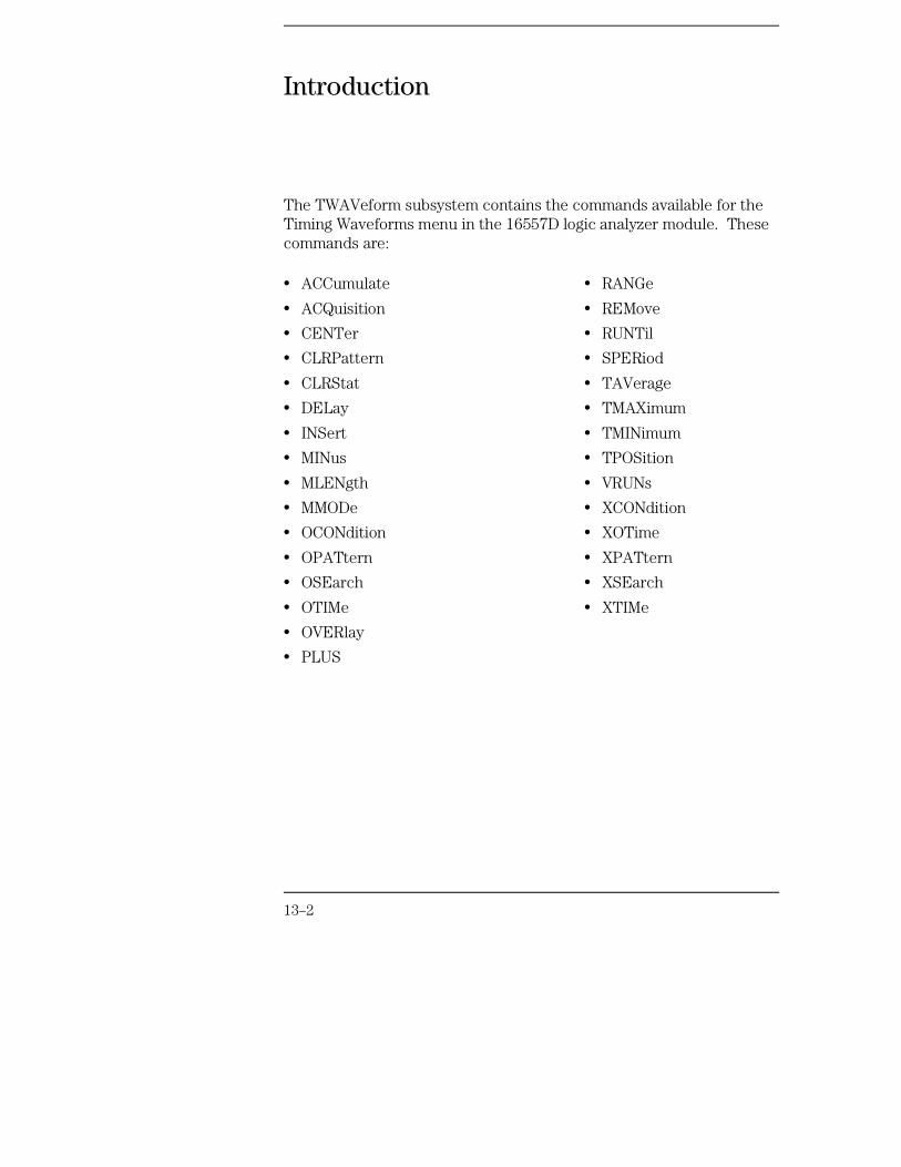
Introduction
The TWAVeform subsystem contains the commands available for theTiming Waveforms menu in the 16557D logic analyzer module. Thesecommands are:
• ACCumulate
• ACQuisition
• CENTer
• CLRPattern
• CLRStat
• DELay
• INSert
• MINus
• MLENgth
• MMODe
• OCONdition
• OPATtern
• OSEarch
• OTIMe
• OVERlay
• PLUS
• RANGe
• REMove
• RUNTil
• SPERiod
• TAVerage
• TMAXimum
• TMINimum
• TPOSition
• VRUNs
• XCONdition
• XOTime
• XPATtern
• XSEarch
• XTIMe
13–2
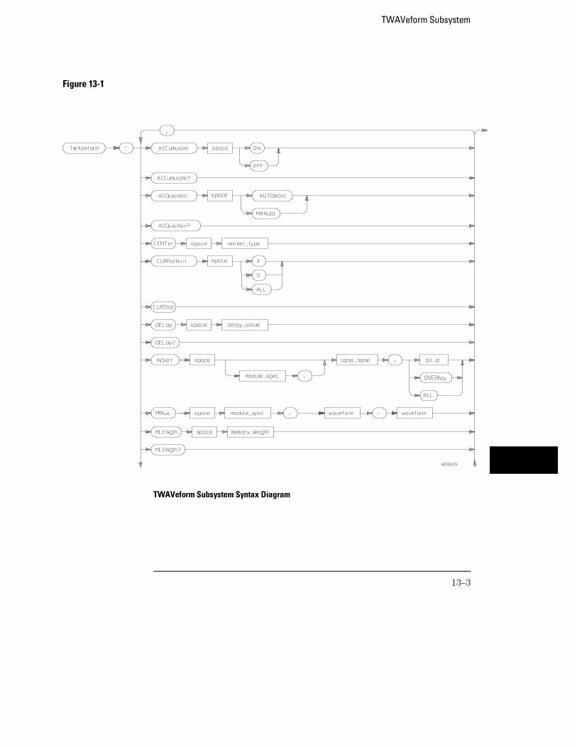
Figure 13-1
TWAVeform Subsystem Syntax Diagram
TWAVeform Subsystem
13–3
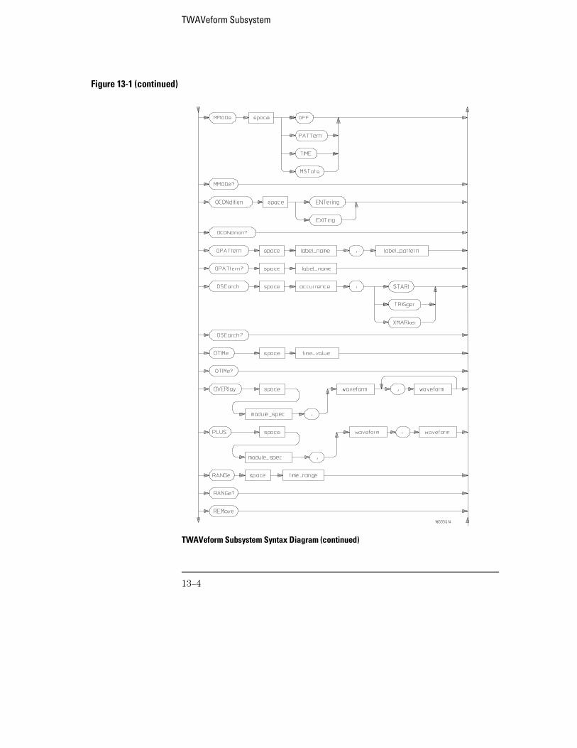
Figure 13-1 (continued)
TWAVeform Subsystem Syntax Diagram (continued)
TWAVeform Subsystem
13–4
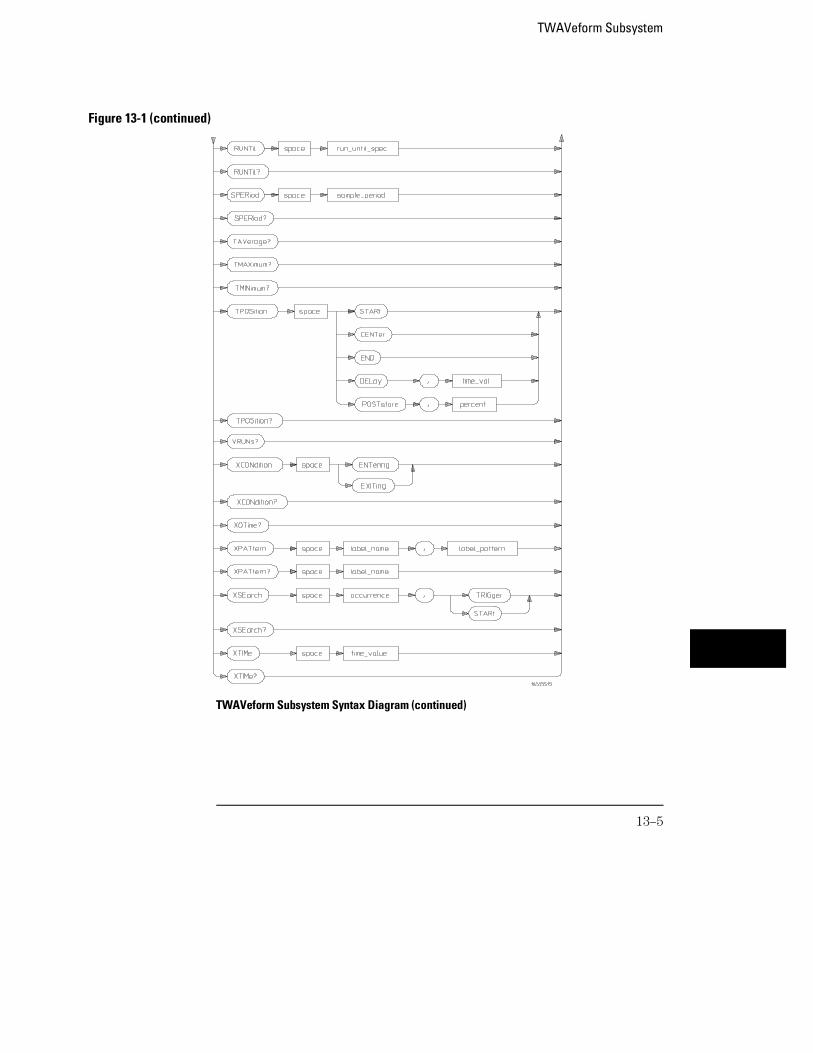
Figure 13-1 (continued)
TWAVeform Subsystem Syntax Diagram (continued)
TWAVeform Subsystem
13–5
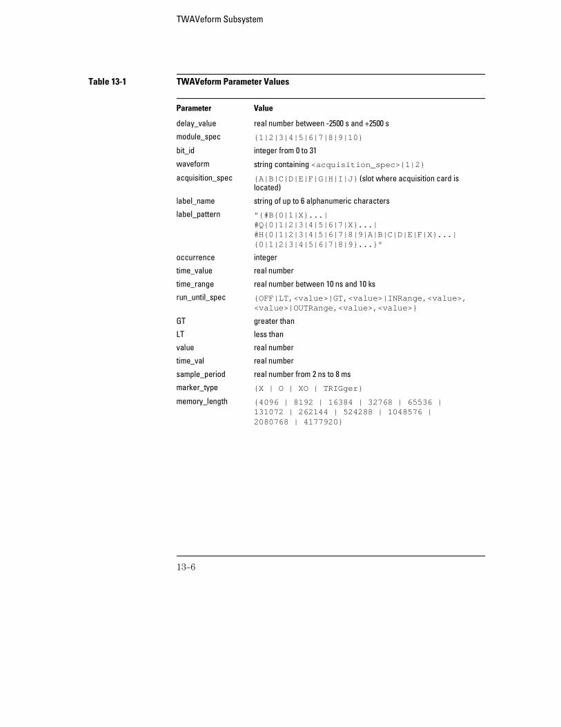
Table 13-1 TWAVeform Parameter Values
Parameter Value
delay_value real number between -2500 s and +2500 s
module_spec {1|2|3|4|5|6|7|8|9|10}
bit_id integer from 0 to 31
waveform string containing <acquisition_spec>{1|2}
acquisition_spec {A|B|C|D|E|F|G|H|I|J} (slot where acquisition card islocated)
label_name string of up to 6 alphanumeric characters
label_pattern "{#B{0|1|X}...|#Q{0|1|2|3|4|5|6|7|X}...|#H{0|1|2|3|4|5|6|7|8|9|A|B|C|D|E|F|X}...|{0|1|2|3|4|5|6|7|8|9}...}"
occurrence integer
time_value real number
time_range real number between 10 ns and 10 ks
run_until_spec {OFF|LT,<value>|GT,<value>|INRange,<value>,<value>|OUTRange,<value>,<value>}
GT greater than
LT less than
value real number
time_val real number
sample_period real number from 2 ns to 8 ms
marker_type {X | O | XO | TRIGger}
memory_length {4096 | 8192 | 16384 | 32768 | 65536 |131072 | 262144 | 524288 | 1048576 |2080768 | 4177920}
TWAVeform Subsystem
13–6
TWAVeform
Selector :MACHine{1|2}:TWAVeform
The TWAVeform selector is used as part of a compound header to access thesettings found in the Timing Waveforms menu. It always follows theMACHine selector because it selects a branch below the MACHine level in thecommand tree.
Example OUTPUT XXX;":MACHINE1:TWAVEFORM:DELAY 100E−9"
ACCumulate
Command :MACHine{1|2}:TWAVeform:ACCumulate <setting>
The ACCumulate command allows you to control whether the waveformdisplay gets erased between each individual run or whether subsequentwaveforms are allowed to be displayed over the previous ones.
<setting> {0|OFF} or {1|ON}
Example OUTPUT XXX;":MACHINE1:TWAVEFORM:ACCUMULATE ON"
TWAVeform SubsystemTWAVeform
13–7
Query :MACHine{1|2}:TWAVeform:ACCumulate?
The ACCumulate query returns the current setting. The query always showsthe setting as the characters, "0" (off) or "1" (on).
Returned Format [:MACHine{1|2}:TWAVeform:ACCumulate] {0|1}<NL>
Example OUTPUT XXX;":MACHINE1:TWAVEFORM:ACCUMULATE?"
ACQuisition
Command :MACHine{1|2}:TWAVeform:ACQuisition{AUTOmatic|MANual}
The ACQuisition command allows you to specify the acquisition mode for thetiming analyzer. The acquisition modes are automatic and manual.
Query MACHine{1|2}:TWAVeform:ACQuisition?
The ACQuisition query returns the current acquisition mode.Returned Format [MACHine{1|2}:TWAVeform:ACQuisition] {AUTOmatic|MANual}<NL>
Example OUTPUT XXX;":MACHINE2:TWAVEFORM:ACQUISITION?"
TWAVeform SubsystemACQuisition
13–8
CENTer
Command :MACHine{1|2}:TWAVeform:CENTer <marker_type>
The CENTer command allows you to center the waveform display about thespecified markers.
<marker_type> {X|O|XO|TRIGger}
Example OUTPUT XXX;":MACHINE1:TWAVEFORM:CENTER X"
CLRPattern
Command :MACHine{1|2}:TWAVeform:CLRPattern {X|O|ALL}
The CLRPattern command allows you to clear the patterns in the selectedSpecify Patterns menu.
Example OUTPUT XXX;":MACHINE1:TWAVEFORM:CLRPATTERN ALL"
CLRStat
Command :MACHine{1|2}:TWAVeform:CLRStat
The CLRStat command allows you to clear the waveform statistics withouthaving to stop and restart the acquisition.
Example OUTPUT XXX;":MACHINE1:TWAVEFORM:CLRSTAT"
TWAVeform SubsystemCENTer
13–9
DELay
Command :MACHine{1|2}:TWAVeform:DELay <delay_value>
The DELay command specifies the amount of time between the timingtrigger and the horizontal center of the the timing waveform display. Theallowable values for delay are −2500 s to +2500 s.
<delay_value> real number between −2500 s and +2500 s
Example OUTPUT XXX;":MACHINE1:TWAVEFORM:DELAY 100E−6"
Query :MACHine{1|2}:TWAVeform:DELay?
The DELay query returns the current time offset (delay) value from thetrigger.
Returned Format [:MACHine{1|2}:TWAVeform:DELay] <time_value><NL>
Example OUTPUT XXX;":MACHINE1:TWAVEFORM:DELAY?"
TWAVeform SubsystemDELay
13–10
INSert
Command :MACHine{1|2}:TWAVeform:INSert [<module_spec>,]<label_name>[,{<bit_id>|OVERlay|ALL}]
The INSert command inserts waveforms in the timing waveform display. Thewaveforms are added from top to bottom up to 96 waveforms. Once 96waveforms are present, each time you insert another waveform, it replacesthe last waveform.
Time-correlated waveforms from an oscilloscope or another logic analyzermodule can also be inserted in the logic analyzer’s timing waveforms display.Oscilloscope waveforms occupy the same display space as three logicanalyzer waveforms. When inserting waveforms from an oscilloscope oranother logic analyzer module, the optional module specifier must be used.1 through 10 corresponds to modules A through J. If you do not specify themodule, the selected module is assumed.
The second parameter specifies the label name that will be inserted. Theoptional third parameter specifies the label bit number, overlay, or all. If anumber is specified, only the waveform for that bit number is added to thescreen.
If you specify OVERlay, all the bits of the label are displayed as a compositeoverlaid waveform. If you specify ALL, all the bits are displayed sequentially.If you do not specify the third parameter, ALL is assumed.
<module_spec> {1|2|3|4|5|6|7|8|9|10}
<label_name> string of up to 6 alphanumeric characters
<bit_id> integer from 0 to 31
Example OUTPUT XXX;":MACHINE1:TWAVEFORM:INSERT 3, ’WAVE’,9"
TWAVeform SubsystemINSert
13–11
Inserting Oscilloscope Waveforms
Command :MACHine{1|2}:TWAVeform:INSert <module_spec>,<label_name>
This inserts a waveform from an oscilloscope to the timing waveforms display.
<module_spec> {1|2|3|4|5|6|7|8|9|10} slot in which the oscilloscope master card isinstalled
<label_name> string of one alpha and one numeric character
Example OUTPUT XXX;":MACHINE1:TWAVEFORM:INSERT 3, ’C1’"
MLENgth
Command :MACHine{1|2}:TWAVeform:MLENgth <memory_length>
The MLENgth command allows you to specify the analyzer memory depth.Valid memory depths range from 4096 samples through the maximum systemmemory depth minus 16384 samples. Memory depth is affected byacquisition mode. If the <memory_depth> value sent with the command isnot a legal value, the closest legal setting will be used.
<memory_length> {4096 | 8192 | 16384 | 32768 | 65536 | 131072 | 262144 | 524288 | 1048576 | 2080768 | 2088960 | 4177920}
Example OUTPUT XXX;":MACHINE1:TWAVEFORM:MLENGTH 262144"
TWAVeform SubsystemMLENgth
13–12

Query :MACHine{1|2}:TWAVeform:MLENgth?
The MLENgth query returns the current analyzer memory depth selection.Returned Format [:MACHine{1|2}:TWAVeform:MLENgth] <memory_length><NL>
Example OUTPUT XXX;":MACHINE1:TWAVEFORM:MLENGTH?"
MINus
Command :MACHine{1|2}:TWAVeform:MINus<module_spec>,<waveform>,<waveform>
The MINus command inserts time-correlated A−B (A minus B) oscilloscopewaveforms on the display. The first parameter specifies where theoscilloscope master card resides, where 1 through 10 refers to slots Athrough J. The next two parameters specify which waveforms will besubtracted from each other.
MINus is only available for oscilloscope waveforms.
<module_spec> {1|2|3|4|5|6|7|8|9|10}
<waveform> string containing <acquisition_spec>{1|2}
<acquisition_spec>
{A|B|C|D|E|F|G|H|I|J} (slot where acquisition card is located)
Example OUTPUT XXX; ":MACHINE1:TWAVEFORM:MINUS 1,’A1’,’A2’"
TWAVeform SubsystemMINus
13–13
MMODe
Command :MACHine{1|2}:TWAVeform:MMODe{OFF|PATTern|TIME|MSTats}
The MMODe (Marker Mode) command selects the mode controlling markermovement and the display of the marker readouts. When PATTern isselected, the markers will be placed on patterns. When TIME is selected, themarkers move on time. In MSTats, the markers are placed on patterns, butthe readouts will be time statistics.
Example OUTPUT XXX; ":MACHINE1:TWAVEFORM:MMODE TIME"
Query :MACHine{1|2}:TWAVeform:MMODe?
The MMODe query returns the current marker mode.Returned Format [:MACHine{1|2}:TWAVeform:MMODe] <marker_mode><NL>
<marker_mode> {OFF|PATTern|TIME|MSTats}
Example OUTPUT XXX;":MACHINE1:TWAVEFORM:MMODE?"
TWAVeform SubsystemMMODe
13–14
OCONdition
Command :MACHine{1|2}:TWAVeform:OCONdition{ENTering|EXITing}
The OCONdition command specifies where the O marker is placed. TheO marker can be placed on the entry or exit point of the OPATtern when inthe PATTern marker mode.
Example OUTPUT XXX; ":MACHINE1:TWAVEFORM:OCONDITION ENTERING"
Query :MACHine{1|2}:TWAVeform:OCONdition?
The OCONdition query returns the current setting.Returned Format [:MACHine{1|2}:TWAVeform:OCONdition] {ENTering|EXITing}<NL>
Example OUTPUT XXX;":MACHINE1:TWAVEFORM:OCONDITION?"
TWAVeform SubsystemOCONdition
13–15
OPATtern
Command :MACHine{1|2}:TWAVeform:OPATtern <label_name>,<label_pattern>
The OPATtern command allows you to construct a pattern recognizer termfor the O marker which is then used with the OSEarch criteria andOCONdition when moving the marker on patterns. Since this command dealswith only one label at a time, a complete specification could require severalinvocations.
When the value of a pattern is expressed in binary, it represents the bitvalues for the label inside the pattern recognizer term. In whatever base isused, the value must be between 0 and 232 − 1, since a label may not havemore than 32 bits. Because the <label_pattern> parameter may containdon’t cares, it is handled as a string of characters rather than a number.
<label_name> string of up to 6 alphanumeric characters
<label_pattern> "{#B{0|1|X} . . . |#Q{0|1|2|3|4|5|6|7|X} . . . |#H{0|1|2|3|4|5|6|7|8|9|A|B|C|D|E|F|X} . . . |{0|1|2|3|4|5|6|7|8|9} . . . }"
Example OUTPUT XXX; ":MACHINE1:TWAVEFORM:OPATTERN ’A’,’511’"
Query :MACHine{1|2}:TWAVeform:OPATtern? <label_name>
The OPATtern query, in pattern marker mode, returns the patternspecification for a given label name. In the time marker mode, the queryreturns the pattern under the O marker for a given label. If the O marker isnot placed on valid data, don’t cares (X) are returned.
Returned Format [:MACHine{1|2}:TWAVeform:OPATtern]<label_name>,<label_pattern><NL>
Example OUTPUT XXX;":MACHINE1:TWAVEFORM:OPATTERN? ’A’"
TWAVeform SubsystemOPATtern
13–16
OSEarch
Command :MACHine{1|2}:TWAVeform:OSEarch <occurrence>,<origin>
The OSEarch command defines the search criteria for the O marker which isthen used with the associated OPATtern specification and the OCONditionwhen moving markers on patterns. The origin parameter tells the marker tobegin a search from the start of the acquisition, the trigger, or the X marker.The actual occurrence the marker searches for is determined by theoccurrence parameter of the OSEArch specification, relative to the origin.An occurrence of 0 places a marker on the selected origin. With a negativeoccurrence, the marker searches before the origin. With a positiveoccurrence, the marker searches after the origin.
<origin> {STARt|TRIGger|XMARker}
<occurrence> integer from –4177920 to +4177920
Example OUTPUT XXX; ":MACHINE1:TWAVEFORM:OSEARCH +10,TRIGGER"
Query :MACHine{1|2}:TWAVeform:OSEarch?
The OSEarch query returns the search criteria for the O marker.Returned Format [:MACHine{1|2}:TWAVeform:OSEarch] <occurrence>,<origin><NL>
Example OUTPUT XXX;":MACHINE1:TWAVEFORM:OSEARCH?"
TWAVeform SubsystemOSEarch
13–17
OTIMe
Command :MACHine{1|2}:TWAVeform:OTIMe <time_value>
The OTIMe command positions the O marker in time when the marker modeis TIME. If data is not valid, the command performs no action.
<time_value> real number −2.5 ks to +2.5 ks
Example OUTPUT XXX; ":MACHINE1:TWAVEFORM:OTIME 30.0E −6"
Query :MACHine{1|2}:TWAVeform:OTIMe?
The OTIMe query returns the O marker position in time. If data is not valid,the query returns 9.9E37.
Returned Format [:MACHine{1|2}:TWAVeform:OTIMe] <time_value><NL>
Example OUTPUT XXX;":MACHINE1:TWAVEFORM:OTIME?"
OVERlay
Command :MACHine{1|2}:TWAVeform:OVERlay <module_number>,<label>,<label>[,<label>]...
The OVERlay command overlays two or more oscilloscope waveforms andadds the resultant waveform to the current waveforms display. The firstparameter of the command specifies which slot contains the oscilloscopemaster card. The next parameters are the labels of the waveforms that are tobe overlaid.
The OVERlay command only works on oscilloscopes. To overlay analyzerwaveforms, use the INSert command with OVERlay option.
TWAVeform SubsystemOTIMe
13–18
<module_spec> {1|2|3|4|5|6|7|8|9|10}
<waveform> string containing <acquisition_spec>{1|2}
<acquisition_spec>
{A|B|C|D|E|F|G|H|I|J} (slot where acquisition card is located)
Example OUTPUT XXX;":MACHINE1:TWAVEFORM:OVERLAY 3, ’C1’,’C2’"
PLUS
Command :MACHine{1|2}:TWAVeform:PLUS<module_spec>,<waveform>,<waveform>
The PLUS command inserts time-correlated A+B oscilloscope waveforms onthe screen. The first parameter specifies the slot where the oscilloscopemodule resides. 1 through 10 refers to slots A through J. The next twoparameters specify which waveforms will be added to each other.
PLUS is only available for oscilloscope waveforms.
<module_spec> {1|2|3|4|5|6|7|8|9|10}
<waveform> string containing <acquisition_spec>{1|2}
<acquisition_spec>
{A|B|C|D|E|F|G|H|I|J} (slot where acquisition card is located)
Example OUTPUT XXX; ":MACHINE1:TWAVEFORM:PLUS 1,’A1’,’A2’"
TWAVeform SubsystemPLUS
13–19
RANGe
Command :MACHine{1|2}:TWAVeform:RANGe <time_value>
The RANGe command specifies the full-screen time in the timing waveformmenu. It is equivalent to ten times the sec/Div setting on the display. Theallowable values for RANGe are from 10 ns to 10 ks.
<time_range> real number between 10 ns and 10 ks
Example OUTPUT XXX;":MACHINE1:TWAVEFORM:RANGE 100E−9"
Query :MACHine{1|2}:TWAVeform:RANGe?
The RANGe query returns the current full-screen time.Returned Format [:MACHine{1|2}:TWAVeform:RANGe] <time_value><NL>
Example OUTPUT XXX;":MACHINE1:TWAVEFORM:RANGE?"
REMove
Command :MACHine{1|2}:TWAVeform:REMove
The REMove command deletes all waveforms from the display.
Example OUTPUT XXX;":MACHINE1:TWAVEFORM:REMOVE"
TWAVeform SubsystemRANGe
13–20
RUNTil
Command :MACHine{1|2}:TWAVeform:RUNTil <run_until_spec>
The RUNTil (run until) command defines stop criteria based on the timebetween the X and O markers when the trace mode is in repetitive. WhenOFF is selected, the analyzer will run until either the STOP touch screen fieldis touched, or, the STOP command is sent. Run until time between X and Omarker options are:
• Less Than (LT) a specified time value.
• Greater Than (GT) a specified time value.
• In range (INRange) between two time values.
• Out of range (OUTRange) between two time values.
End points for INRange and OUTRange should be at least 2 ns apart sincethis is the minimum time at which data is sampled.
This command affects the timing analyzer only, and has no relation to theRUNTil commands in the SLISt and COMPare subsystems.
<run_until_spec>
{OFF | LT,<value> | GT,<value> | INRange,<value>,<value>| OUTRange,<value>,<value>}
<value> real number
Example OUTPUT XXX;":MACHINE1:TWAVEFORM:RUNTIL GT, 800.0E −6"OUTPUT XXX;":MACHINE1:TWAVEFORM:RUNTIL INRANGE, 4.5, 5.5"
Query :MACHine{1|2}:TWAVeform:RUNTil?
The RUNTil query returns the current stop criteria.Returned Format [:MACHine{1|2}:TWAVeform:RUNTil] <run_until_spec><NL>
Example OUTPUT XXX;":MACHINE1:TWAVEFORM:RUNTIL?"
TWAVeform SubsystemRUNTil
13–21
SPERiod
Command :MACHine{1|2}:TWAVeform:SPERiod <sample_period>
The SPERiod command allows you to set the sample period of the timinganalyzer.
<sample_period> real number from 2 ns to 8 ms
Example OUTPUT XXX;":MACHINE1:TWAVEFORM:SPERIOD 50E−9"
Query :MACHine{1|2}:TWAVeform:SPERiod?
The SPERiod query returns the current sample period.Returned Format [:MACHine{1|2}:TWAVeform:SPERiod] <sample_period><NL>
Example OUTPUT XXX;":MACHINE1:TWAVEFORM:SPERIOD?"
TWAVeform SubsystemSPERiod
13–22

TAVerage
Query :MACHine{1|2}:TWAVeform:TAVerage?
The TAVerage query returns the value of the average time between theX and O markers. If there is no valid data, the query returns 9.9E37.
Returned Format [:MACHine{1|2}:TWAVeform:TAVerage] <time_value><NL>
<time_value> real number
Example OUTPUT XXX;":MACHINE1:TWAVEFORM:TAVERAGE?"
TMAXimum
Query :MACHine{1|2}:TWAVeform:TMAXimum?
The TMAXimum query returns the value of the maximum time between the Xand O markers. If there is no valid data, the query returns 9.9E37.
Returned Format [:MACHine{1|2}:TWAVeform:TMAXimum] <time_value><NL>
<time_value> real number
Example OUTPUT XXX;":MACHINE1:TWAVEFORM:TMAXIMUM?"
TWAVeform SubsystemTAVerage
13–23
TMINimum
Query :MACHine{1|2}:TWAVeform:TMINimum?
The TMINimum query returns the value of the minimum time between the Xand O markers. If there is no valid data, the query returns 9.9E37.
Returned Format [:MACHine{1|2}:TWAVeform:TMINimum] <time_value><NL>
<time_value> real number
Example OUTPUT XXX;":MACHINE1:TWAVEFORM:TMINIMUM?"
TPOSition
Command MACHine{1|2}:TWAVeform:TPOSition{STARt |CENTer | END | DELay, <time_val> |POSTstore, <percent>}
The TPOSition command allows you to control where the trigger point isplaced in the acquisition. The trigger point can be placed at the start, center,end, at a percentage of post store, or at a value specified by delay. The poststore option is the same as the User Defined option when setting the triggerpoint from the front panel.
The TPOSition command is only available when the acquisition mode is set tomanual.
<time_val> real number that varies by sample period
<percent> integer from 1 to 100
Example OUTPUT XXX;":MACHINE2:TWAVEFORM:TPOSITION CENTER"
TWAVeform SubsystemTMINimum
13–24
Query MACHine{1|2}:TWAVeform:TPOSition?
The TPOSition query returns the current trigger setting.Returned Format [MACHine{1|2}:TWAVeform:TPOSition] {STARt|CENTer|END|DELay,
<time_val>| POSTstore,<percent>}<NL>
Example OUTPUT XXX;":MACHINE2:TWAVEFORM:TPOSition?"
VRUNs
Query :MACHine{1|2}:TWAVeform:VRUNs?
The VRUNs query returns the number of valid runs and total number of runsmade. Valid runs are those where the pattern search for both the X and Omarkers was successful resulting in valid time measurements.
Returned Format [:MACHine{1|2}:TWAVeform:VRUNs] <valid_runs>,<total_runs><NL>
<valid_runs> zero or positive integer
<total_runs> zero or positive integer
Example OUTPUT XXX;":MACHINE1:TWAVEFORM:VRUNS?"
TWAVeform SubsystemVRUNs
13–25
XCONdition
Command :MACHine{1|2}:TWAVeform:XCONdition{ENTering | EXITing}
The XCONdition command specifies where the X marker is placed. The Xmarker can be placed on the entry or exit point of the XPATtern when in thePATTern marker mode.
Example OUTPUT XXX; ":MACHINE1:TWAVEFORM:XCONDITION ENTERING"
Query :MACHine{1|2}:TWAVeform:XCONdition?
The XCONdition query returns the current setting.Returned Format [:MACHine{1|2}:TWAVeform:XCONdition] {ENTering|EXITing}<NL>
Example OUTPUT XXX;":MACHINE1:TWAVEFORM:XCONDITION?"
XOTime
Query :MACHine{1|2}:TWAVeform:XOTime?
The XOTime query returns the time from the X marker to the O marker. Ifdata is not valid, the query returns 9.9E37.
Returned Format [:MACHine{1|2}:TWAVeform:XOTime] <time_value><NL>
<time_value> real number
Example OUTPUT XXX;":MACHINE1:TWAVEFORM:XOTIME?"
TWAVeform SubsystemXCONdition
13–26
XPATtern
Command :MACHine{1|2}:TWAVeform:XPATtern<label_name>,<label_pattern>
The XPATtern command allows you to construct a pattern for the X markerwhich is then used with the XSEarch criteria and XCONdition when movingthe marker on patterns. Since this command deals with only one label at atime, a complete specification could require several iterations.
When the value of a pattern is expressed in binary, it represents the bitvalues for the label inside the pattern. In whatever base is used, the valuemust be between 0 and 232 − 1, since a label may not have more than 32 bits.Because the <label_pattern> parameter may contain don’t cares, it ishandled as a string of characters rather than a number.
<label_name> string of up to 6 alphanumeric characters
<label_pattern> "{#B{0|1|X} . . . |#Q{0|1|2|3|4|5|6|7|X} . . . |#H{0|1|2|3|4|5|6|7|8|9|A|B|C|D|E|F|X} . . . |{0|1|2|3|4|5|6|7|8|9} . . . }"
Example OUTPUT XXX; ":MACHINE1:TWAVEFORM:XPATTERN ’A’,’511’"
Query :MACHine{1|2}:TWAVeform:XPATtern? <label_name>
The XPATtern query, in pattern marker mode, returns the patternspecification for a given label name. In the time marker mode, the queryreturns the pattern under the X marker for a given label. If the X marker isnot placed on valid data, don’t cares (X) are returned.
Returned Format [:MACHine{1|2}:TWAVeform:XPATtern]<label_name>,<label_pattern><NL>
Example OUTPUT XXX;":MACHINE1:TWAVEFORM:XPATTERN? ’A’"
TWAVeform SubsystemXPATtern
13–27
XSEarch
Command :MACHine{1|2}:TWAVeform:XSEarch<occurrence>,<origin>
The XSEarch command defines the search criteria for the X marker. Thecriteria are then used with the associated XPATtern specification and theXCONdition when moving markers on patterns. The origin parameter tellsthe marker to begin a search from the trigger or start. The occurrenceparameter determines which occurrence of the XPATtern recognizerspecification, relative to the origin, the marker actually searches for. Anoccurrence of 0 places a marker on the origin.
<origin> {TRIGger|STARt}
<occurrence> integer from from –4177920 to +4177920
Example OUTPUT XXX; ":MACHINE1:TWAVEFORM:XSEARCH,+10,TRIGGER"
Query :MACHine{1|2}:TWAVeform:XSEarch?<occurrence>, <origin>
The XSEarch query returns the search criteria for the X marker.Returned Format [:MACHine{1|2}:TWAVeform:XSEarch] <occurrence>,<origin><NL>
Example OUTPUT XXX;":MACHINE1:TWAVEFORM:XSEARCH?"
TWAVeform SubsystemXSEarch
13–28
XTIMe
Command :MACHine{1|2}:TWAVeform:XTIMe <time_value>
The XTIMe command positions the X marker in time when the marker modeis time. If data is not valid, the command performs no action.
<time_value> real number from −2.5 ks to +2.5 ks
Example OUTPUT XXX; ":MACHINE1:TWAVEFORM:XTIME 40.0E −6"
Query :MACHine{1|2}:TWAVeform:XTIMe?
The XTIMe query returns the X marker position in time. If data is not valid,the query returns 9.9E37.
Returned Format [:MACHine{1|2}:TWAVeform:XTIMe] <time_value><NL>
Example OUTPUT XXX;":MACHINE1:TWAVEFORM:XTIME?"
TWAVeform SubsystemXTIMe
13–29

13–30
14
TLISt Subsystem
Introduction
The TLISt subsystem contains the commands available for the TimingListing menu in the 16557D logic analyzer module and is the same asthe SLISt subsystem (except for the OCONdition and XCONditioncommands). The TLISt subsystem commands are:
• COLumn
• CLRPattern
• DATA
• LINE
• MMODe
• OCONdition
• OPATtern
• OSEarch
• OSTate
• OTAG
• REMove
• RUNTil
• TAVerage
• TMAXimum
• TMINimum
• VRUNs
• XCONdition
• XOTag
• XOTime
• XPATtern
• XSEarch
• XSTate
• XTAG
14–2
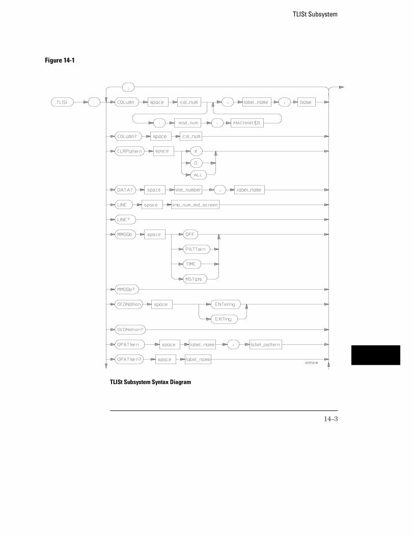
Figure 14-1
TLISt Subsystem Syntax Diagram
TLISt Subsystem
14–3
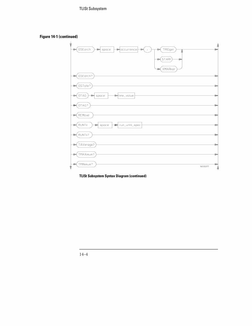
Figure 14-1 (continued)
TLISt Subsystem Syntax Diagram (continued)
TLISt Subsystem
14–4
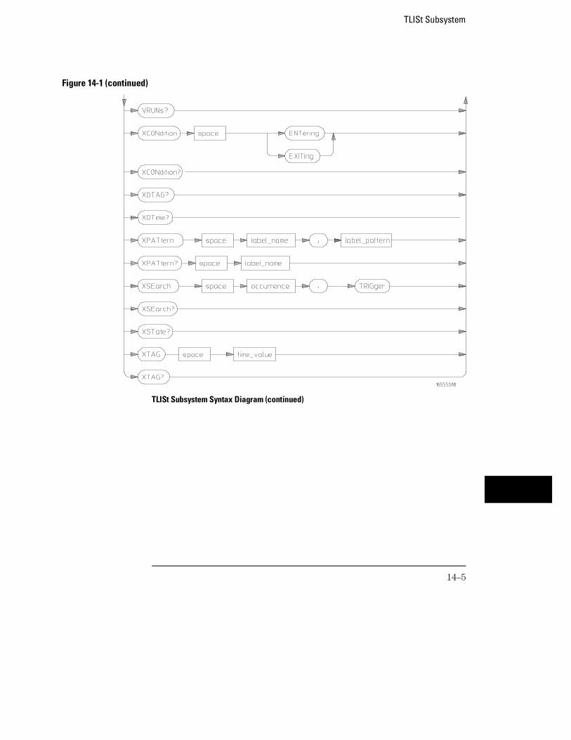
Figure 14-1 (continued)
TLISt Subsystem Syntax Diagram (continued)
TLISt Subsystem
14–5
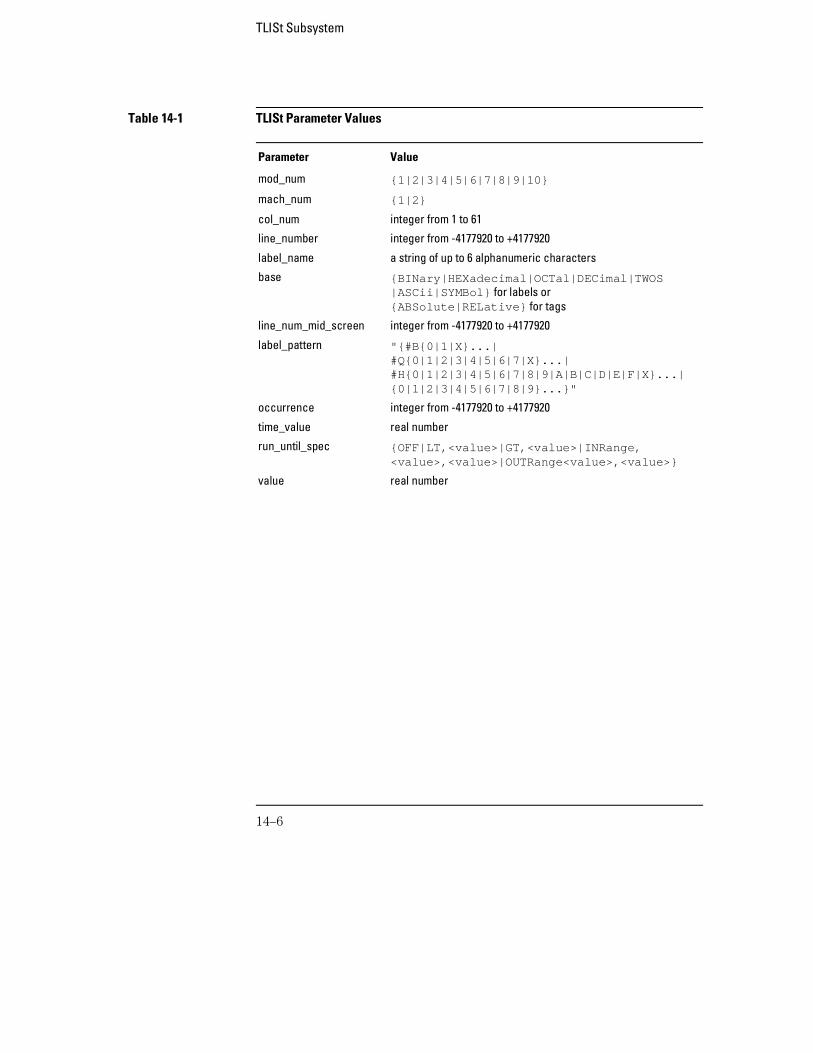
Table 14-1 TLISt Parameter Values
Parameter Value
mod_num {1|2|3|4|5|6|7|8|9|10}
mach_num {1|2}
col_num integer from 1 to 61
line_number integer from -4177920 to +4177920
label_name a string of up to 6 alphanumeric characters
base {BINary|HEXadecimal|OCTal|DECimal|TWOS|ASCii|SYMBol} for labels or{ABSolute|RELative} for tags
line_num_mid_screen integer from -4177920 to +4177920
label_pattern "{#B{0|1|X}...|#Q{0|1|2|3|4|5|6|7|X}...|#H{0|1|2|3|4|5|6|7|8|9|A|B|C|D|E|F|X}...|{0|1|2|3|4|5|6|7|8|9}...}"
occurrence integer from -4177920 to +4177920
time_value real number
run_until_spec {OFF|LT,<value>|GT,<value>|INRange,<value>,<value>|OUTRange<value>,<value>}
value real number
TLISt Subsystem
14–6
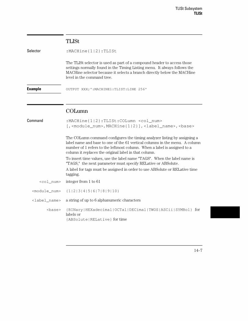
TLISt
Selector :MACHine{1|2}:TLISt
The TLISt selector is used as part of a compound header to access thosesettings normally found in the Timing Listing menu. It always follows theMACHine selector because it selects a branch directly below the MACHinelevel in the command tree.
Example OUTPUT XXX;":MACHINE1:TLIST:LINE 256"
COLumn
Command :MACHine{1|2}:TLISt:COLumn <col_num>[,<module_num>,MACHine{1|2}],<label_name>,<base>
The COLumn command configures the timing analyzer listing by assigning alabel name and base to one of the 61 vertical columns in the menu. A columnnumber of 1 refers to the leftmost column. When a label is assigned to acolumn it replaces the original label in that column.
To insert time values, use the label name "TAGS". When the label name is"TAGS," the next parameter must specify RELative or ABSolute.
A label for tags must be assigned in order to use ABSolute or RELative timetagging.
<col_num> integer from 1 to 61
<module_num> {1|2|3|4|5|6|7|8|9|10}
<label_name> a string of up to 6 alphanumeric characters
<base> {BINary|HEXadecimal|OCTal|DECimal|TWOS|ASCii|SYMBol} forlabels or {ABSolute|RELative} for time
TLISt SubsystemTLISt
14–7
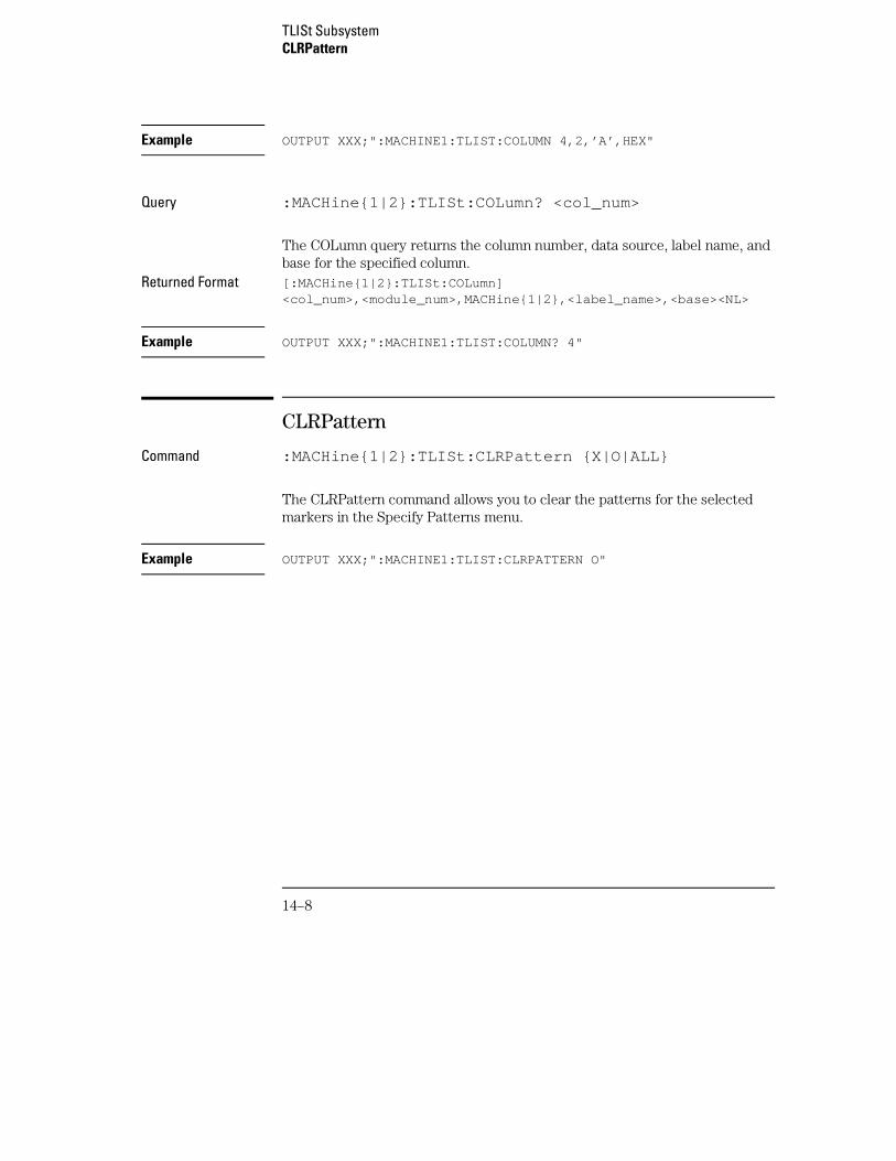
Example OUTPUT XXX;":MACHINE1:TLIST:COLUMN 4,2,’A’,HEX"
Query :MACHine{1|2}:TLISt:COLumn? <col_num>
The COLumn query returns the column number, data source, label name, andbase for the specified column.
Returned Format [:MACHine{1|2}:TLISt:COLumn]<col_num>,<module_num>,MACHine{1|2},<label_name>,<base><NL>
Example OUTPUT XXX;":MACHINE1:TLIST:COLUMN? 4"
CLRPattern
Command :MACHine{1|2}:TLISt:CLRPattern {X|O|ALL}
The CLRPattern command allows you to clear the patterns for the selectedmarkers in the Specify Patterns menu.
Example OUTPUT XXX;":MACHINE1:TLIST:CLRPATTERN O"
TLISt SubsystemCLRPattern
14–8
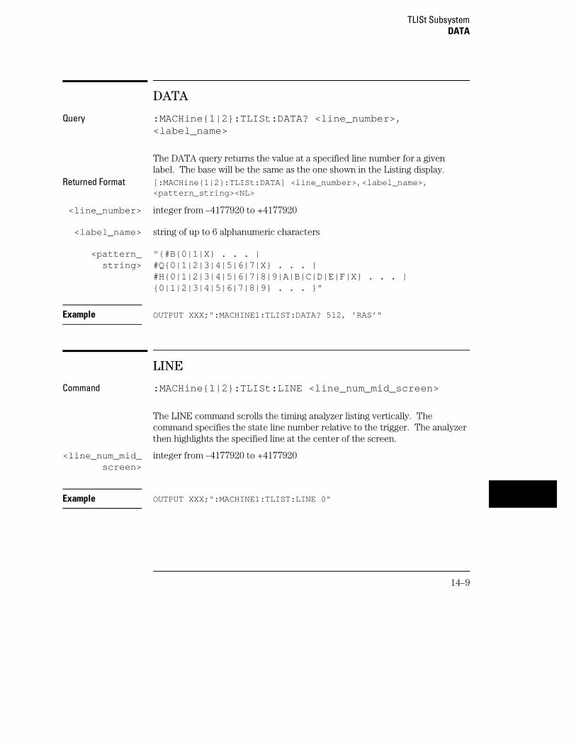
DATA
Query :MACHine{1|2}:TLISt:DATA? <line_number>,<label_name>
The DATA query returns the value at a specified line number for a givenlabel. The base will be the same as the one shown in the Listing display.
Returned Format [:MACHine{1|2}:TLISt:DATA] <line_number>,<label_name>,<pattern_string><NL>
<line_number> integer from –4177920 to +4177920
<label_name> string of up to 6 alphanumeric characters
<pattern_string>
"{#B{0|1|X} . . . |#Q{0|1|2|3|4|5|6|7|X} . . . |#H{0|1|2|3|4|5|6|7|8|9|A|B|C|D|E|F|X} . . . |{0|1|2|3|4|5|6|7|8|9} . . . }"
Example OUTPUT XXX;":MACHINE1:TLIST:DATA? 512, ’RAS’"
LINE
Command :MACHine{1|2}:TLISt:LINE <line_num_mid_screen>
The LINE command scrolls the timing analyzer listing vertically. Thecommand specifies the state line number relative to the trigger. The analyzerthen highlights the specified line at the center of the screen.
<line_num_mid_screen>
integer from –4177920 to +4177920
Example OUTPUT XXX;":MACHINE1:TLIST:LINE 0"
TLISt SubsystemDATA
14–9
Query :MACHine{1|2}:TLISt:LINE?
The LINE query returns the line number for the state currently in the dataroll box at the center of the screen.
Returned Format [:MACHine{1|2}:TLISt:LINE] <line_num_mid_screen><NL>
Example OUTPUT XXX;":MACHINE1:TLIST:LINE?"
MMODe
Command :MACHine{1|2}:TLISt:MMODe <marker_mode>
The MMODe command (Marker Mode) selects the mode controlling themarker movement and the display of marker readouts. When PATTern isselected, the markers will be placed on patterns. When TIME is selected themarkers move on time between stored states. When MSTats is selected themarkers are placed on patterns, but the readouts will be time statistics.
<marker_mode> {OFF|PATTern|TIME|MSTats}
Example OUTPUT XXX;":MACHINE1:TLIST:MMODE TIME"
Query :MACHine{1|2}:TLISt:MMODe?
The MMODe query returns the current marker mode selected.Returned Format [:MACHine{1|2}:TLISt:MMODe] <marker_mode><NL>
Example OUTPUT XXX;":MACHINE1:TLIST:MMODE?"
TLISt SubsystemMMODe
14–10
OCONdition
Command :MACHine{1|2}:TLISt:OCONdition {ENTering|EXITing}
The OCONdition command specifies where the O marker is placed. TheO marker can be placed on the entry or exit point of the OPATtern when inthe PATTern marker mode.
Example OUTPUT XXX; ":MACHINE1:TLIST:OCONDITION ENTERING"
Query :MACHine{1|2}:TLISt:OCONdition?
The OCONdition query returns the current setting.Returned Format [:MACHine{1|2}:TLISt:OCONdition] {ENTering|EXITing}<NL>
Example OUTPUT XXX;":MACHINE1:TLIST:OCONDITION?"
TLISt SubsystemOCONdition
14–11
OPATtern
Command :MACHine{1|2}:TLISt:OPATtern <label_name>,<label_pattern>
The OPATtern command allows you to construct a pattern for the O markerwhich is then used with the OSEarch criteria when moving the marker onpatterns. Since this command deals with only one label at a time, a completespecification could require several iterations.
When the value of a pattern is expressed in binary, it represents the bitvalues for the label inside the pattern recognizer term. In whatever base isused, the value must be between 0 and 232 − 1, since a label may not havemore than 32 bits. Because the <label_pattern> parameter may containdon’t cares, it is handled as a string of characters rather than a number.
<label_name> string of up to 6 alphanumeric characters
<label_pattern> "{#B{0|1|X} . . . |#Q{0|1|2|3|4|5|6|7|X} . . . |#H{0|1|2|3|4|5|6|7|8|9|A|B|C|D|E|F|X} . . . |{0|1|2|3|4|5|6|7|8|9} . . . }"
Example OUTPUT XXX;":MACHINE1:TLIST:OPATTERN ’DATA’,’255’ "OUTPUT XXX;":MACHINE1:TLIST:OPATTERN ’ABC’,’#BXXXX1101’ "
Query :MACHine{1|2}:TLISt:OPATtern? <label_name>
The OPATtern query returns the pattern specification for a given label name.Returned Format [:MACHine{1|2}:TLISt:OPATtern] <label_name>,
<label_pattern><NL>
Example OUTPUT XXX;":MACHINE1:TLIST:OPATTERN? ’A’"
TLISt SubsystemOPATtern
14–12
OSEarch
Command :MACHine{1|2}:TLISt:OSEarch <occurrence>,<origin>
The OSEarch command defines the search criteria for the O marker, which isthen used with associated OPATtern recognizer specification when movingthe markers on patterns. The origin parameter tells the marker to begin asearch from the trigger, the start of data, or the X marker. The actualoccurrence the marker searches for is determined by the occurrenceparameter, relative to the origin. An occurrence of 0 places the marker onthe selected origin. With a negative occurrence, the marker searches beforethe origin. With a positive occurrence, the marker searches after the origin.
<occurrence> integer from –4177920 to +4177920
<origin> {TRIGger|STARt|XMARker}
Example OUTPUT XXX;":MACHINE1:TLIST:OSEARCH +10,TRIGGER"
Query :MACHine{1|2}:TLISt:OSEarch?
The OSEarch query returns the search criteria for the O marker. Returned Format [:MACHine{1|2}:TLISt:OSEarch] <occurrence>,<origin><NL>
Example OUTPUT XXX;":MACHINE1:TLIST:OSEARCH?"
TLISt SubsystemOSEarch
14–13
OSTate
Query :MACHine{1|2}:TLISt:OSTate?
The OSTate query returns the line number in the listing where the O markerresides. If data is not valid, the query returns 2147483647.
Returned Format [:MACHine{1|2}:TLISt:OSTate] <state_num><NL>
<state_num> 2147483647 or integer from –4177920 to +4177920
Example OUTPUT XXX;":MACHINE1:TLIST:OSTATE?"
OTAG
Command :MACHine{1|2}:TLISt:OTAG <time_value>
The OTAG command specifies the tag value on which the O marker should beplaced. The tag value is always time for the timing analyzer. If the data isnot valid tagged data, no action is performed.
<time_value> real number
Example :OUTPUT XXX;":MACHINE1:TLIST:OTAG 40.0E −6"
TLISt SubsystemOSTate
14–14
Query :MACHine{1|2}:TLISt:OTAG?
The OTAG query returns the O marker position in time regardless of whetherthe marker was positioned in time or through a pattern search. If data is notvalid, the query returns 9.9E37.
Returned Format [:MACHine{1|2}:TLISt:OTAG] <time_value><NL>
Example OUTPUT XXX;":MACHINE1:TLIST:OTAG?"
REMove
Command :MACHine{1|2}:TLISt:REMove
The REMove command removes all labels, except the leftmost label, from thelisting menu.
Example OUTPUT XXX;":MACHINE1:TLIST:REMOVE"
TLISt SubsystemREMove
14–15
RUNTil
Command :MACHine{1|2}:TLISt:RUNTil <run_until_spec>
The RUNTil (run until) command allows you to define a stop condition whenthe run mode is repetitive. Specifying OFF causes the analyzer to make runsuntil either the display’s STOP field is touched or the STOP command isissued.
There are four conditions based on the time between the X and O markers.These four conditions are as follows:
• The difference is less than (LT) some value.
• The difference is greater than (GT) some value.
• The difference is inside some range (INRange).
• The difference is outside some range (OUTRange).
End points for INRange and OUTRange should be at least 2 ns apart sincethis is the minimum time between samples.
<run_until_spec>
{OFF|LT,<value>|GT,<value>|INRange,<value>,<value>|OUTRange,<value>,<value>}
<value> real number from −9E9 to +9E9
Example OUTPUT XXX;":MACHINE1:TLIST:RUNTIL GT,800.0E −6"
Query :MACHine{1|2}:TLISt:RUNTil?
The RUNTil query returns the current stop criteria.Returned Format [:MACHine{1|2}:TLISt:RUNTil] <run_until_spec><NL>
Example OUTPUT XXX;":MACHINE1:TLIST:RUNTIL?"
TLISt SubsystemRUNTil
14–16
TAVerage
Query :MACHine{1|2}:TLISt:TAVerage?
The TAVerage query returns the value of the average time between the Xand O markers. If the number of valid runs is zero, the query returns 9.9E37.Valid runs are those where the pattern search for both the X and O markerswas successful, resulting in valid time measurements.
Returned Format [:MACHine{1|2}:TLISt:TAVerage] <time_value><NL>
<time_value> real number
Example OUTPUT XXX;":MACHINE1:TLIST:TAVERAGE?"
TMAXimum
Query :MACHine{1|2}:TLISt:TMAXimum?
The TMAXimum query returns the value of the maximum time between the Xand O markers. If data is not valid, the query returns 9.9E37.
Returned Format [:MACHine{1|2}:TLISt:TMAXimum] <time_value><NL>
<time_value> real number
Example OUTPUT XXX;":MACHINE1:TLIST:TMAXIMUM?"
TLISt SubsystemTAVerage
14–17

TMINimum
Query :MACHine{1|2}:TLISt:TMINimum?
The TMINimum query returns the value of the minimum time between the Xand O markers. If data is not valid, the query returns 9.9E37.
Returned Format [:MACHine{1|2}:TLISt:TMINimum] <time_value><NL>
<time_value> real number
Example OUTPUT XXX;":MACHINE1:TLIST:TMINIMUM?"
VRUNs
Query :MACHine{1|2}:TLISt:VRUNs?
The VRUNs query returns the number of valid runs and total number of runsmade. Valid runs are those where the pattern search for both the X andO markers was successful resulting in valid time measurements.
Returned Format [:MACHine{1|2}:TLISt:VRUNs] <valid_runs>,<total_runs><NL>
<valid_runs> zero or positive integer
<total_runs> zero or positive integer
Example OUTPUT XXX;":MACHINE1:TLIST:VRUNS?"
TLISt SubsystemTMINimum
14–18
XCONdition
Command :MACHine{1|2}:TLISt:XCONdition {ENTering|EXITing}
The XCONdition command specifies where the X marker is placed. TheX marker can be placed on the entry or exit point of the XPATtern when inthe PATTern marker mode.
Example OUTPUT XXX; ":MACHINE1:TLIST:XCONDITION ENTERING"
Query :MACHine{1|2}:TLISt:XCONdition?
The XCONdition query returns the current setting.Returned Format [:MACHine{1|2}:TLISt:XCONdition] {ENTering|EXITing}<NL>
Example OUTPUT XXX;":MACHINE1:TLIST:XCONDITION?"
XOTag
Query :MACHine{1|2}:TLISt:XOTag?
The XOTag query returns the time from the X to the O marker. If there is nodata the query returns 9.9E37.
Returned Format [:MACHine{1|2}:TLISt:XOTag] <XO_time><NL>
<XO_time> real number
Example OUTPUT XXX;":MACHINE1:TLIST:XOTAG?"
TLISt SubsystemXCONdition
14–19
XOTime
Query :MACHine{1|2}:TLISt:XOTime?
The XOTime query returns the time from the X to O markers. If there is nodata the query returns 9.9E37.
Returned Format [:MACHine{1|2}:TLISt:XOTime] <XO_time><NL>
<XO_time> real number
Example OUTPUT XXX;":MACHINE1:TLIST:XOTIME?"
XPATtern
Command :MACHine{1|2}:TLISt:XPATtern <label_name>,<label_pattern>
The XPATtern command allows you to construct a pattern for the X markerwhich is then used with the XSEarch criteria when moving the marker onpatterns. Since this command deals with only one label at a time, a completespecification could require several iterations.
When the value of a pattern is expressed in binary, it represents the bitvalues for the label inside the pattern recognizer term. In whatever base isused, the value must be between 0 and 232 − 1, since a label may not havemore than 32 bits. Because the <label_pattern> parameter may containdon’t cares, it is handled as a string of characters rather than a number.
<label_name> string of up to 6 alphanumeric characters
<label_pattern> "{#B{0|1|X} . . . |#Q{0|1|2|3|4|5|6|7|X} . . . |#H{0|1|2|3|4|5|6|7|8|9|A|B|C|D|E|F|X} . . . |{0|1|2|3|4|5|6|7|8|9} . . . }"
TLISt SubsystemXOTime
14–20
Example OUTPUT XXX;":MACHINE1:TLIST:XPATTERN ’DATA’,’255’ "OUTPUT XXX;":MACHINE1:TLIST:XPATTERN ’ABC’,’#BXXXX1101’ "
Query :MACHine{1|2}:TLISt:XPATtern? <label_name>
The XPATtern query returns the pattern specification for a given label name.Returned Format [:MACHine{1|2}:TLISt:XPATtern] <label_name>,
<label_pattern><NL>
Example OUTPUT XXX;":MACHINE1:TLIST:XPATTERN? ’A’"
XSEarch
Command :MACHine{1|2}:TLISt:XSEarch <occurrence>,<origin>
The XSEarch command defines the search criteria for the X marker, which isthen used with the associated XPATtern specification when moving themarkers on patterns. The origin parameter tells the marker to begin a searchfrom the trigger or the start of data. The occurrence parameter determineswhich occurrence of the X pattern, relative to the origin, the marker actuallysearches for. An occurrence of 0 places a marker on the selected origin.
<occurrence> integer from –4177920 to +4177920
<origin> {TRIGger|STARt}
Example OUTPUT XXX;":MACHINE1:TLIST:XSEARCH +10,TRIGGER"
TLISt SubsystemXSEarch
14–21
Query :MACHine{1|2}:TLISt:XSEarch?
The XSEarch query returns the search criteria for the X marker. Returned Format [:MACHine{1|2}:TLISt:XSEarch] <occurrence>,<origin><NL>
Example OUTPUT XXX;":MACHINE1:TLIST:XSEARCH?"
XSTate
Query :MACHine{1|2}:TLISt:XSTate?
The XSTate query returns the line number in the listing where the X markerresides. If data is not valid, the query returns 2147483647.
Returned Format [:MACHine{1|2}:TLISt:XSTate] <state_num><NL>
<state_num> 2147483647 or integer from –4177920 to +4177920.
Example OUTPUT XXX;":MACHINE1:TLIST:XSTATE?"
TLISt SubsystemXSTate
14–22
XTAG
Command :MACHine{1|2}:TLISt:XTAG <time_value>
The XTAG command specifies the tag value on which the X marker should beplaced. The tag value is always time for the timing analyzer. If the data isnot valid tagged data, no action is performed.
<time_value> real number
Example OUTPUT XXX;":MACHINE1:TLIST:XTAG 40.0E −6"
Query :MACHine{1|2}:TLISt:XTAG?
The XTAG query returns the X marker position in time regardless of whetherthe marker was positioned in time or through a pattern search. If data is notvalid tagged data, the query returns 9.9E37.
Returned Format [:MACHine{1|2}:TLISt:XTAG] <time_value><NL>
Example OUTPUT XXX;":MACHINE1:TLIST:XTAG?"
TLISt SubsystemXTAG
14–23

14–24
15
SYMBol Subsystem
Introduction
The SYMBol subsystem contains the commands that allow you todefine symbols on the controller and download them to the 16557Dlogic analyzer module. The commands in this subsystem are:
• BASE
• PATTern
• RANGe
• REMove
• WIDTh
15–2
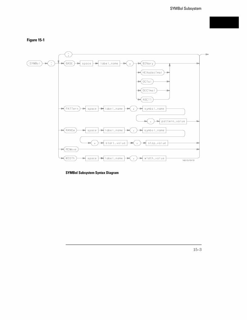
SYMBol Subsystem Syntax Diagram
Figure 15-1
SYMBol Subsystem
15–3
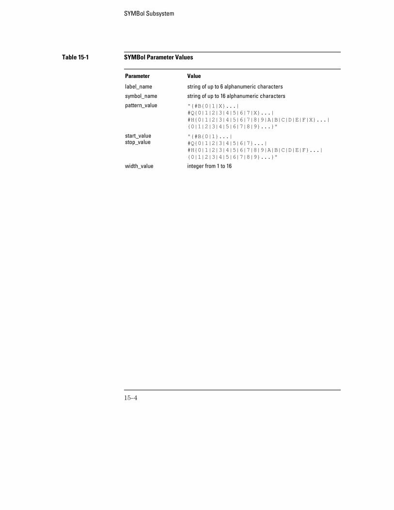
Table 15-1 SYMBol Parameter Values
Parameter Value
label_name string of up to 6 alphanumeric characters
symbol_name string of up to 16 alphanumeric characters
pattern_value "{#B{0|1|X}...| #Q{0|1|2|3|4|5|6|7|X}...|#H{0|1|2|3|4|5|6|7|8|9|A|B|C|D|E|F|X}...| {0|1|2|3|4|5|6|7|8|9}...}"
start_valuestop_value
"{#B{0|1}...|#Q{0|1|2|3|4|5|6|7}...|#H{0|1|2|3|4|5|6|7|8|9|A|B|C|D|E|F}...|{0|1|2|3|4|5|6|7|8|9}...}"
width_value integer from 1 to 16
SYMBol Subsystem
15–4
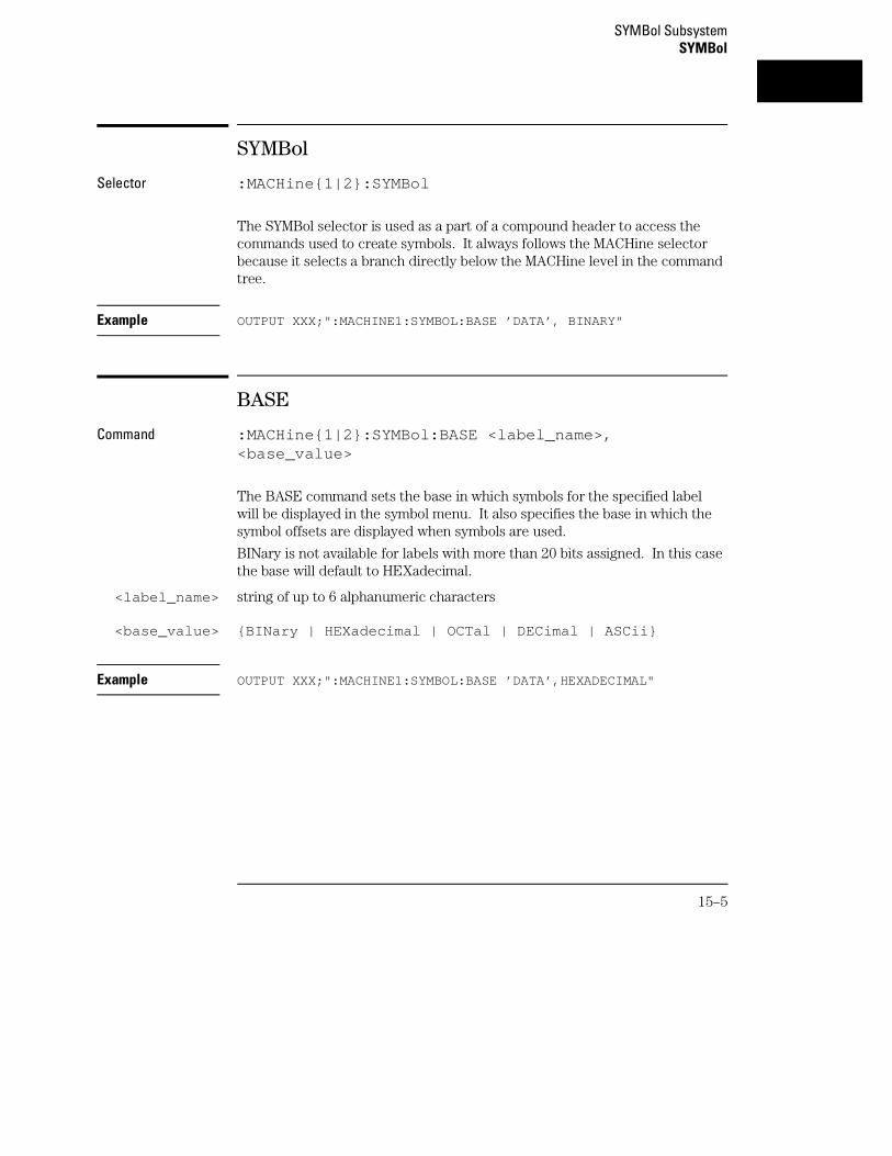
SYMBol
Selector :MACHine{1|2}:SYMBol
The SYMBol selector is used as a part of a compound header to access thecommands used to create symbols. It always follows the MACHine selectorbecause it selects a branch directly below the MACHine level in the commandtree.
Example OUTPUT XXX;":MACHINE1:SYMBOL:BASE ’DATA’, BINARY"
BASE
Command :MACHine{1|2}:SYMBol:BASE <label_name>,<base_value>
The BASE command sets the base in which symbols for the specified labelwill be displayed in the symbol menu. It also specifies the base in which thesymbol offsets are displayed when symbols are used.
BINary is not available for labels with more than 20 bits assigned. In this casethe base will default to HEXadecimal.
<label_name> string of up to 6 alphanumeric characters
<base_value> {BINary | HEXadecimal | OCTal | DECimal | ASCii}
Example OUTPUT XXX;":MACHINE1:SYMBOL:BASE ’DATA’,HEXADECIMAL"
SYMBol SubsystemSYMBol
15–5
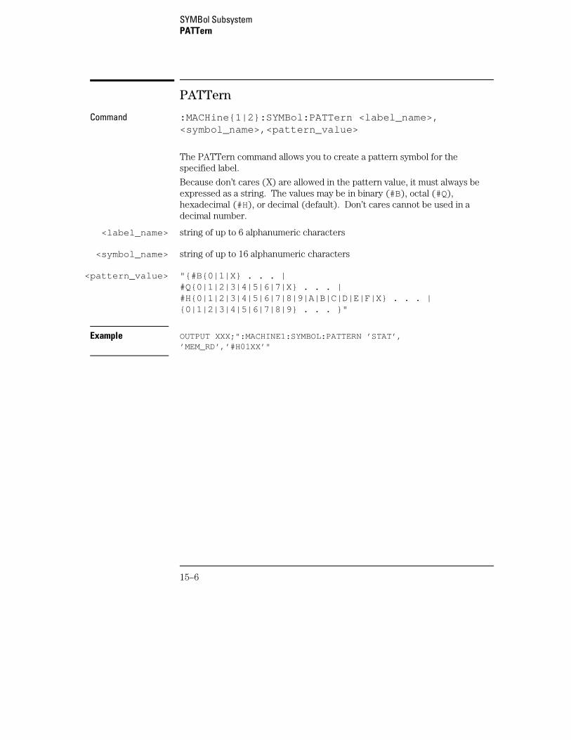
PATTern
Command :MACHine{1|2}:SYMBol:PATTern <label_name>,<symbol_name>,<pattern_value>
The PATTern command allows you to create a pattern symbol for thespecified label.
Because don’t cares (X) are allowed in the pattern value, it must always beexpressed as a string. The values may be in binary (#B), octal (#Q),hexadecimal (#H), or decimal (default). Don’t cares cannot be used in adecimal number.
<label_name> string of up to 6 alphanumeric characters
<symbol_name> string of up to 16 alphanumeric characters
<pattern_value> "{#B{0|1|X} . . . |#Q{0|1|2|3|4|5|6|7|X} . . . |#H{0|1|2|3|4|5|6|7|8|9|A|B|C|D|E|F|X} . . . |{0|1|2|3|4|5|6|7|8|9} . . . }"
Example OUTPUT XXX;":MACHINE1:SYMBOL:PATTERN ’STAT’,’MEM_RD’,’#H01XX’"
SYMBol SubsystemPATTern
15–6
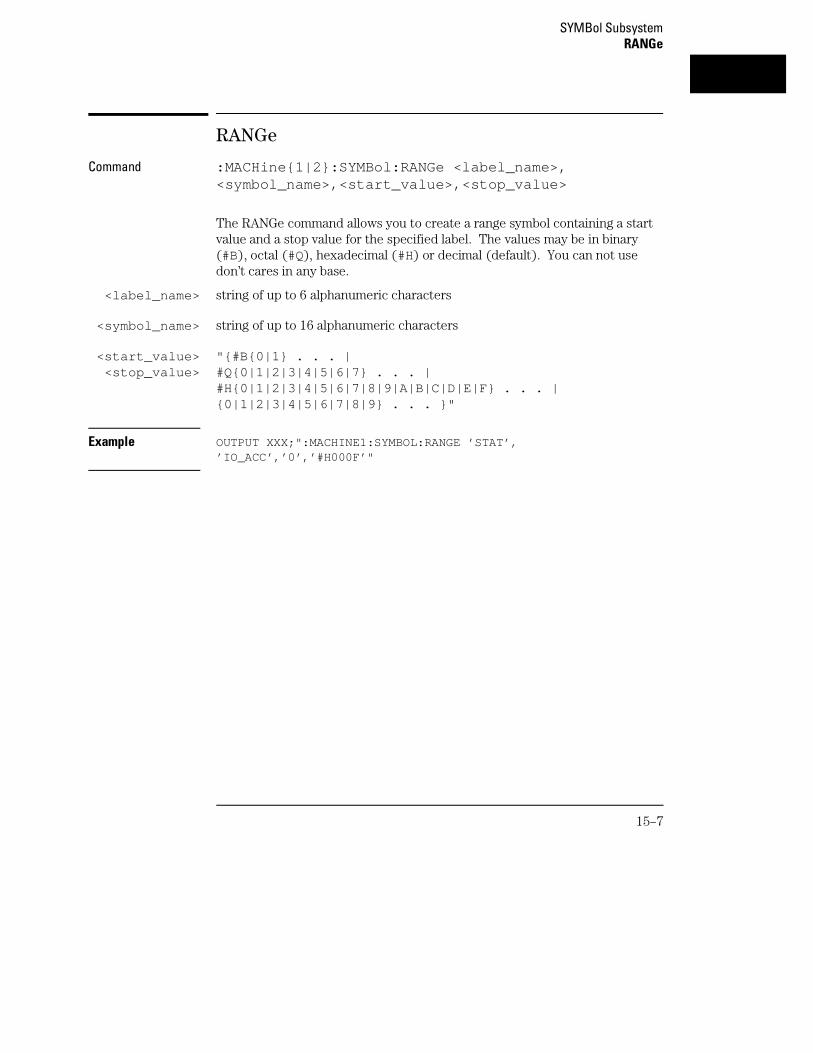
RANGe
Command :MACHine{1|2}:SYMBol:RANGe <label_name>,<symbol_name>,<start_value>,<stop_value>
The RANGe command allows you to create a range symbol containing a startvalue and a stop value for the specified label. The values may be in binary(#B), octal (#Q), hexadecimal (#H) or decimal (default). You can not usedon’t cares in any base.
<label_name> string of up to 6 alphanumeric characters
<symbol_name> string of up to 16 alphanumeric characters
<start_value><stop_value>
"{#B{0|1} . . . |#Q{0|1|2|3|4|5|6|7} . . . |#H{0|1|2|3|4|5|6|7|8|9|A|B|C|D|E|F} . . . |{0|1|2|3|4|5|6|7|8|9} . . . }"
Example OUTPUT XXX;":MACHINE1:SYMBOL:RANGE ’STAT’,’IO_ACC’,’0’,’#H000F’"
SYMBol SubsystemRANGe
15–7
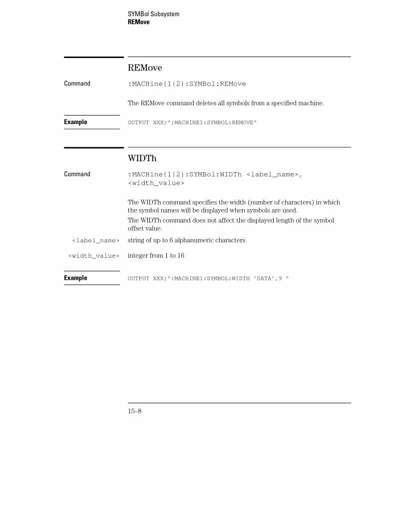
REMove
Command :MACHine{1|2}:SYMBol:REMove
The REMove command deletes all symbols from a specified machine.
Example OUTPUT XXX;":MACHINE1:SYMBOL:REMOVE"
WIDTh
Command :MACHine{1|2}:SYMBol:WIDTh <label_name>,<width_value>
The WIDTh command specifies the width (number of characters) in whichthe symbol names will be displayed when symbols are used.
The WIDTh command does not affect the displayed length of the symboloffset value.
<label_name> string of up to 6 alphanumeric characters
<width_value> integer from 1 to 16
Example OUTPUT XXX;":MACHINE1:SYMBOL:WIDTH ’DATA’,9 "
SYMBol SubsystemREMove
15–8
16
SPA Subsystem
Introduction
This chapter provides you with information for programming theSystem Performance Analysis (SPA) features on the 16557D logicanalyzer module.
SPA commands have subsystems, indicated by the outdented items inthe list. Indented commands must be prefaced with the outdentedcommand above it unless MODE was previously used to set the mode.The SPA commands are:
• OVERView • TINTerval
• BUCKet • AUTorange
• HIGH • QUALifier
• LABel • TINTerval
• LOW • TSTatistic
• MLENgth • MODE
• OMARker
• OVSTatistic
• XMARker
• HISTogram
• HISTatistic
• LABel
• OTHer
• QUALifier
• RANGe
• TTYPe
16–2
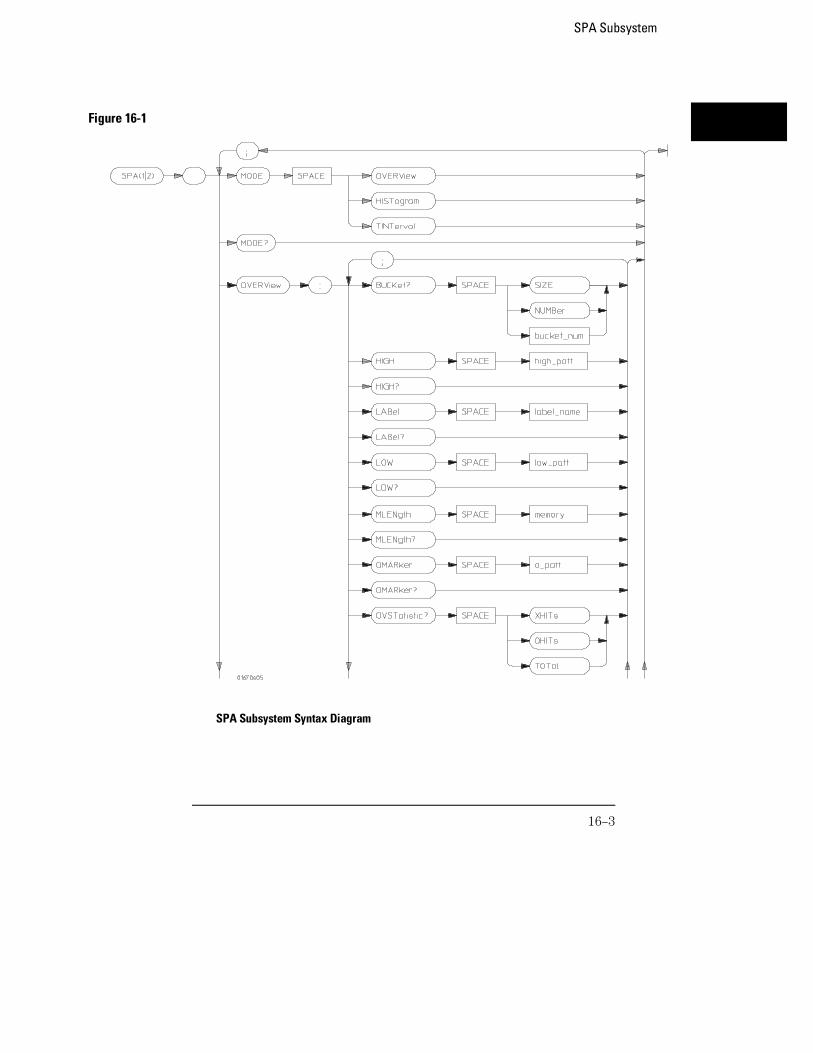
Figure 16-1
SPA Subsystem Syntax Diagram
SPA Subsystem
16–3
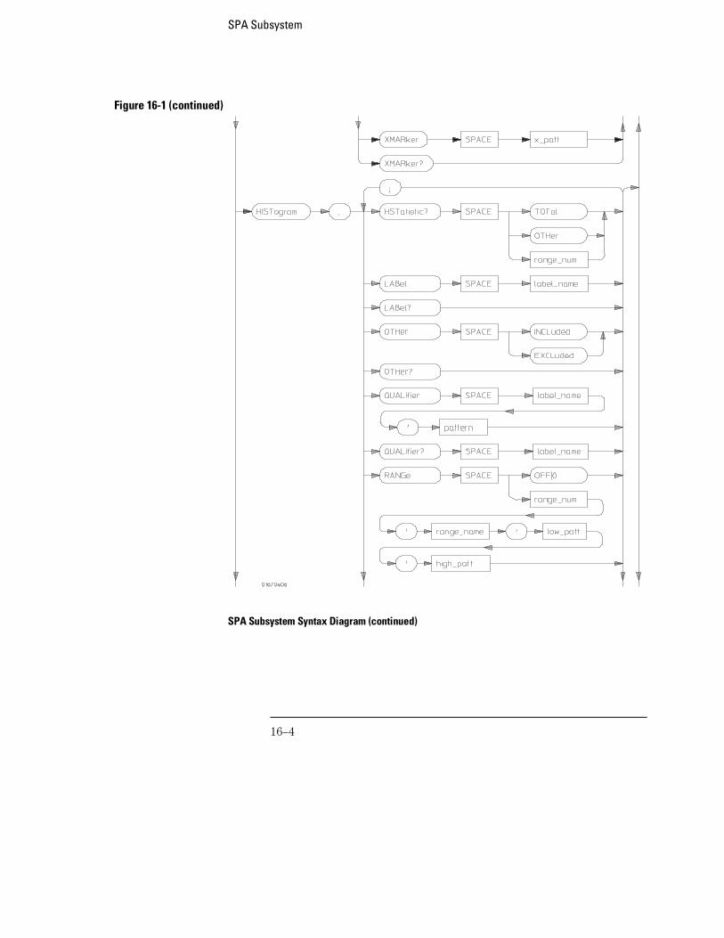
Figure 16-1 (continued)
SPA Subsystem Syntax Diagram (continued)
SPA Subsystem
16–4
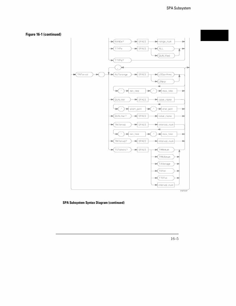
Figure 16-1 (continued)
SPA Subsystem Syntax Diagram (continued)
SPA Subsystem
16–5
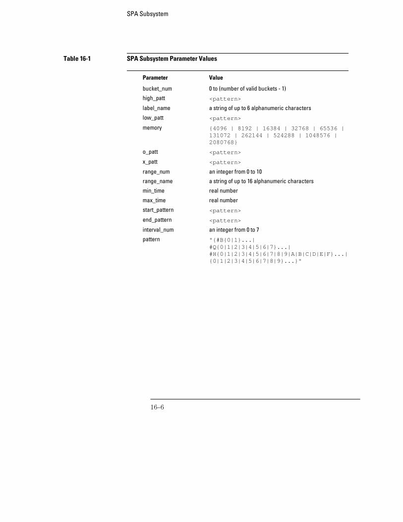
Table 16-1 SPA Subsystem Parameter Values
Parameter Value
bucket_num 0 to (number of valid buckets - 1)
high_patt <pattern>
label_name a string of up to 6 alphanumeric characters
low_patt <pattern>
memory {4096 | 8192 | 16384 | 32768 | 65536 |131072 | 262144 | 524288 | 1048576 |2080768}
o_patt <pattern>
x_patt <pattern>
range_num an integer from 0 to 10
range_name a string of up to 16 alphanumeric characters
min_time real number
max_time real number
start_pattern <pattern>
end_pattern <pattern>
interval_num an integer from 0 to 7
pattern "{#B{0|1}...|#Q{0|1|2|3|4|5|6|7}...|#H{0|1|2|3|4|5|6|7|8|9|A|B|C|D|E|F}...|{0|1|2|3|4|5|6|7|8|9}...}"
SPA Subsystem
16–6
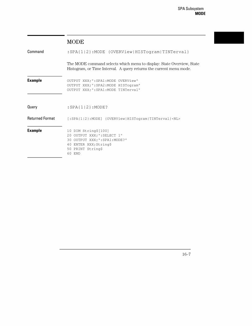
MODE
Command :SPA{1|2}:MODE {OVERView|HISTogram|TINTerval}
The MODE command selects which menu to display: State Overview, StateHistogram, or Time Interval. A query returns the current menu mode.
Example OUTPUT XXX;":SPA1:MODE OVERView"OUTPUT XXX;":SPA2:MODE HISTogram"OUTPUT XXX;":SPA1:MODE TINTerval"
Query :SPA{1|2}:MODE?
Returned Format [:SPA{1|2}:MODE] {OVERView|HISTogram|TINTerval}<NL>
Example 10 DIM String$[100]20 OUTPUT XXX;":SELECT 1"30 OUTPUT XXX;":SPA1:MODE?"40 ENTER XXX;String$50 PRINT String$60 END
SPA Subsystem MODE
16–7
OVERView:BUCKet
Query :SPA{1|2}:OVERView:BUCKet?{SIZE|NUMBer|<bucket_num>}
The OVERView:BUCKet query returns data relating to the State Overviewmeasurement. You specify SIZE for width of each bucket, NUMBer fornumber of buckets, or <bucket_num> for the number of hits in the specifiedbucket number
Returned Format [:SPA{1|2}:OVERView:BUCKet] {SIZE|NUMBer|<bucket_num>},<number><NL>
<bucket_num> 0 to (number of valid buckets – 1)
<number> integer number
Example 10 DIM String$[100]20 OUTPUT XXX;":SELECT 1"30 OUTPUT XXX;":SPA2:OVERView:BUCKet? 23"40 ENTER XXX;String$50 PRINT String$60 END
SPA SubsystemOVERView:BUCKet
16–8
OVERView:HIGH
Command :SPA{1|2}:OVERView:HIGH <high_pattern>
The OVERView:HIGH command sets the upper boundary of the StateOverview measurement. A query returns the current setting of the upperboundary.
Setting the upper boundary defaults the data accumulators, statisticcounters, and the number of buckets and their size.
<high_pattern> "{#B{0|1}...|#Q{0|1|2|3|4|5|6|7}...|#H{0|1|2|3|4|5|6|7|8|9|A|B|C|D|E|F}.. .|{0|1|2|3|4|5|6|7|8|9}...}"
Example OUTPUT XXX;":SPA1:OVERView:HIGH ’23394’"OUTPUT XXX;":SPA2:OVERView:HIGH ’#Q4371’"
Query :SPA{1|2}:OVERView:HIGH?
Returned Format [:SPA{1|2}:OVERView:HIGH] <high_pattern><NL>
Example 10 DIM String$[100]20 OUTPUT XXX;":SELECT 1"30 OUTPUT XXX;":SPA1:OVERView:HIGH?"40 ENTER XXX;String$50 PRINT String$60 END
SPA Subsystem OVERView:HIGH
16–9
OVERView:LABel
Command :SPA{1|2}:OVERView:LABel <label_name>
The OVERView:LABel command selects a new label for collecting the SPAmeasurements. A query returns the name of the currently selected label.
Selecting a new label defaults the State Overview data accumulators, statisticcounters, and the number of buckets and their size.
<label_name> string of up to 6 alphanumeric characters
Example OUTPUT XXX;":SPA2:OVERView:LABel ’A’"
Query :SPA{1|2}:OVERView:LABel?
Returned Format: [:SPA{1|2}:OVERView:LABel] <label_name><NL>
Example 10 DIM String$[100]20 OUTPUT XXX;":SELECT 1"30 OUTPUT XXX;":SPA2:OVERView:LABel?"40 ENTER XXX;String$50 PRINT String$60 END
SPA SubsystemOVERView:LABel
16–10

OVERView:LOW
Command :SPA{1|2}:OVERView:LOW <low_pattern>
The OVERView:LOW command sets the lower boundary of the StateOverview measurement. A query returns the current setting of the lowerboundary.
Setting the lower boundary defaults the data accumulators, statistic counters,and the number of buckets and their size.
<low_pattern> "{#B{0|1}...|#Q{0|1|2|3|4|5|6|7}...|#H{0|1|2|3|4|5|6|7|8|9|A|B|C|D|E|F}...|{0|1|2|3|4|5|6|7|8|9}...}"
Example OUTPUT XXX;":SPA2:OVERView:LOW ’23394’"OUTPUT XXX;":SPA1:OVERView:LOW ’#Q4371’"
Query :SPA{1|2}:OVERView:LOW?
Returned Format [:SPA{1|2}:OVERView:LOW] <low_pattern><NL>
Example 10 DIM String$[100]20 OUTPUT XXX;":SELECT 1"30 OUTPUT XXX;":SPA1:OVERView:LOW?"40 ENTER XXX;String$50 PRINT String$60 END
SPA Subsystem OVERView:LOW
16–11
OVERView:MLENgth
Command :SPA{1|2}:OVERView:MLENgth <memory_length>
The MLENgth command specifies the memory depth. Valid memory depthsrange from 4096 states (or samples) through the maximum system memorydepth minus 16384 states. Memory depth is affected by acquisition mode. Ifthe <memory_length> value sent with the command is not a legal value, theclosest legal setting will be used.
<memory_length> {4096 | 8192 | 16384 | 32768 | 65536 | 131072 | 262144 | 524288 | 1048576 | 2080768}
Example OUTPUT XXX;":SPA1:OVERVIEW:MLENGTH 262144"
Query :SPA{1|2}:OVERView:MLENgth?
The MLENgth query returns the current analyzer memory depth selection.Returned Format [:SPA{1|2}:OVERView:MLENgth] <memory_length><NL>
Example OUTPUT XXX;":SPA1:OVERVIEW:MLENGTH?"
SPA SubsystemOVERView:MLENgth
16–12

OVERView:OMARker
Command :SPA{1|2}:OVERView:OMARker <o_pattern>
The OVERView:OMARker command sends the O marker to the lowerboundary of the bucket where the specified pattern is located. A request toplace the marker outside the defined boundary forces the marker to theappropriate end bucket. A query returns the pattern associated with thelower end of the bucket where the marker is placed.
<o_pattern> "{#B{0|1}...|#Q{0|1|2|3|4|5|6|7}...|#H{0|1|2|3|4|5|6|7|8|9|A|B|C|D|E|F}...|{0|1|2|3|4|5|6|7|8|9}...}"
Example OUTPUT XXX;":SPA2:OVERView:OMARker ’#H3C31’"
Query :SPA{1|2}:OVERView:OMARker?
Returned Format [:SPA{1|2}:OVERView:OMARker] <o_pattern><NL>
Example 10 DIM String$[100]20 OUTPUT XXX;":SELECT 1"30 OUTPUT XXX;":SPA1:OVERView:OMARker?"40 ENTER XXX;String$50 PRINT String$60 END
SPA Subsystem OVERView:OMARker
16–13
OVERView:OVSTatistic
Query :SPA{1|2}:OVERView:OVSTatistic?{XHITs|OHITs|TOTal}
The OVERView:OVSTatistic query returns the number of hits associated withthe requested statistic or returns the number of hits in the specified bucket.XHITs requests the number of hits in the bucket where the X marker islocated. OHITs requests the number of hits in the bucket where theO marker is located. TOTal requests the total number of hits.
Returned Format [:SPA{1|2}:OVERView:OVSTatistic] {XHITs|OHITs|TOTal},<number_hits><NL>
<number_hits> integer number
Example 10 DIM String$[100]20 OUTPUT XXX;":SELECT 1"30 OUTPUT XXX;":SPA2:OVERView:OVSTatistic? OHITs"40 ENTER XXX;String$50 PRINT String$60 END
SPA SubsystemOVERView:OVSTatistic
16–14
OVERView:XMARker
Command :SPA{1|2}:OVERView:XMARker <x_pattern>
The OVERView:XMARker command sends the X marker to the lowerboundary of the bucket where the specified pattern is located. A request toplace the marker outside the defined boundary forces the marker to theappropriate end bucket. A query returns the pattern associated with thelower end of the bucket where the marker is placed.
<x_pattern> "{#B{0|1}...|#Q{0|1|2|3|4|5|6|7}...|#H{0|1|2|3|4|5|6|7|8|9|A|B|C|D|E|F}...|{0|1|2|3|4|5|6|7|8|9}...}"
Example OUTPUT XXX;":SPA2:OVERView:XMARker ’#H3C31’"
Query :SPA{1|2}:OVERView:XMARker?
Returned Format [:SPA{1|2}:OVERView:XMARker] <x_pattern><NL>
Example 10 DIM String$[100]20 OUTPUT XXX;":SELECT 1"30 OUTPUT XXX;":SPA2:OVERView:XMARker?"40 ENTER XXX;String$50 PRINT String$60 END
SPA Subsystem OVERView:XMARker
16–15
HISTogram:HSTatistic
Query :SPA{1|2}:HISTogram:HSTatistic?{TOTal|OTHer|<range_number>}
The HISTogram:HSTatistic query returns the total number of samples orreturns the number of samples in the specified range. Specify TOTal for thetotal number of samples, OTHer for the number of hits in "other" range, or<range_number> for the number of hits in that range.
Depending on whether the "other" range is on or off, the statistic TOTalincludes or excludes the number of hits in the "other" range.
Returned Format [:SPA{1|2}:HISTogram:HSTatistic] {TOTal|OTHer|<range_number>},<number_hits><NL>
<range_number> 0 to 10
<number_hits> integer number
Example 10 DIM String$[100]20 OUTPUT XXX;":SELECT 1"30 OUTPUT XXX;":SPA1:HISTogram:HSTatistic? 7"40 ENTER XXX;String$50 PRINT String$60 END
SPA SubsystemHISTogram:HSTatistic
16–16
HISTogram:LABel
Command :SPA{1|2}:HISTogram:LABel <label_name>
The HISTogram:LABel command selects a new label for collecting SPAmeasurements. A query returns the name of the currently selected label.
Selecting a new label defaults the State Histogram range names, bucket sizes,and hit accumulators.
<label_name> string of up to 6 alphanumeric characters
Example OUTPUT XXX;":SPA2:HISTogram:LABel ’A’"
Query :SPA{1|2}:HISTogram:LABel?
Returned Format [:SPA{1|2}:HISTogram:LABel] <label_name><NL>
Example 10 DIM String$[100]20 OUTPUT XXX;":SELECT 1"30 OUTPUT XXX;":SPA2:HISTogram:LABel?"40 ENTER XXX;String$50 PRINT String$60 END
SPA Subsystem HISTogram:LABel
16–17
HISTogram:OTHer
Command :SPA{1|2}:HISTogram:OTHer {INCLuded|EXCLuded}
The HISTogram:OTHer command selects including or excluding the "other"histogram bucket. A query returns data indicating whether the "other"bucket is currently included or excluded.
Example OUTPUT XXX;":SPA2:HISTogram:OTHer INCLuded"OUTPUT XXX;":SPA1:HISTogram:OTHer EXCLuded"
Query :SPA{1|2}:HISTogram:OTHer?
Returned Format [:SPA{1|2}:HISTogram:OTHer] {INCLuded|EXCLuded}<NL>
Example 10 DIM String$[100]20 OUTPUT XXX;":SELECT 1"30 OUTPUT XXX;":SPA2:HISTogram:OTHer?"40 ENTER XXX;String$50 PRINT String$60 END
SPA SubsystemHISTogram:OTHer
16–18
HISTogram:QUALifier
Command :SPA{1|2}:HISTogram:QUALifier <label_name>,<pattern>
The HISTogram:QUALifier command sets the pattern associated with thespecified label. The pattern is a condition for triggering and storing themeasurement. A query of a label returns the current pattern setting for thatlabel.
<label_name> string of up to 6 alphanumeric characters
<pattern> "{#B{0|1}...|#Q{0|1|2|3|4|5|6|7}...|#H{0|1|2|3|4|5|6|7|8|9|A|B|C|D|E|F}...|{0|1|2|3|4|5|6|7|8|9}...}"
Example OUTPUT XXX;":SPA2:HISTogram:QUALifier ’A’,’255’"
Query :SPA{1|2}:HISTogram:QUALifier? <label_name>
Returned Format [:SPA{1|2}:HISTogram:QUALifier] <label_name>,<pattern><NL>
Example 10 DIM String$[100]20 OUTPUT XXX;":SELECT 1"30 OUTPUT XXX;":SPA1:HISTogram:QUALifier? ’A’"40 ENTER XXX;String$50 PRINT String$60 END
SPA Subsystem HISTogram:QUALifier
16–19
HISTogram:RANGe
Command :SPA{1|2}:HISTogram:RANGe {OFF | <range_num>,<range_name>,<low_patt>,<high_patt>}
The HISTogram:RANGe command turns off all ranges or defines the rangename, low boundary, and high boundary of the specified range. Defining aspecified range turns on that range. For the specified range, a query returnsthe name, low boundary, high boundary, and whether the range is on or off.
<range_num> 0 to 10
<range_name> string of up to 16 alphanumeric characters
<low_patt><high_patt>
"{#B{0|1}...|#Q{0|1|2|3|4|5|6|7}...|#H{0|1|2|3|4|5|6|7|8|9|A|B|C|D|E|F}...|{0|1|2|3|4|5|6|7|8|9}...}"
Example OUTPUT XXX;":SPA1:HISTogram:RANGe OFF"OUTPUT XXX;":SPA2:HISTogram:RANGe 5,’A’,’255’,’512’"OUTPUT XXX;":SPA1:HISTogram:RANGe 8,’DATA’,’#B0100110’,’#H9F’"
Query :SPA{1|2}:HISTogram:RANGe? <range_num>
Returned Format [:SPA{1|2}:HISTogram:RANGe] <range_number>,<range_name>,<low_pattern>,<high_pattern>,<range_onoff><NL>
<range_onoff> {ON|OFF}
Example 10 DIM String$[100]20 OUTPUT XXX;":SELECT 1"30 OUTPUT XXX;":SPA1:HISTogram:RANGe? 4"40 ENTER XXX;String$50 PRINT String$60 END
SPA SubsystemHISTogram:RANGe
16–20
HISTogram:TTYPe
Command :SPA{1|2}:HISTogram:TTYPe {ALL|QUALified}
The HISTogram:TTYPe command sets the trigger to trigger on anystate or onqualified state. A query returns the current trace type setting.
Example OUTPUT XXX;":SPA2:HISTogram:TTYPe ALL"
Query :SPA{1|2}:HISTogram:TTYPe?
Returned Format [:SPA{1|2}:HISTogram:TTYPe] {ALL|QUALified}<NL>
Example 10 DIM String$[100]20 OUTPUT XXX;":SELECT 1"30 OUTPUT XXX;":SPA1:HISTogram:TTYPe?"40 ENTER XXX;String$50 PRINT String$60 END
SPA Subsystem HISTogram:TTYPe
16–21
TINTerval:AUTorange
Command :SPA{1|2}:TINTerval:AUTorange{LOGarithmic|LINear},<min_time>,<max_time>
The TINTerval:AUTorange command automatically sets the Time Intervalranges in a logarithmic or linear distribution over the specified range of time.When the AUTorange command is executed, the data accumulators andstatistic counters are reset.
<min_time> real number
<max_time> real number
Example
OUTPUT XXX;":SPA2:TINTerval:AUTorange LINear,4.0E-3,55.6E+2"OUTPUT XXX;":SPA1:TINTerval:AUTorange LOGarithmic,3.3E+1,8.6E+2"
SPA SubsystemTINTerval:AUTorange
16–22
TINTerval:QUALifier
Command :SPA{1|2}:TINTerval:QUALifier <label_name>,<start_pattern>,<end_pattern>
The TINTerval:QUALifier command defines the start and stop patterns for aspecified label. The start and stop patterns determine the time windows forcollecting data. A query returns the currently defined start and stop patternsfor a given label.
<label_name> string of up to 6 alphanumeric characters
<start_pattern> "{#B{0|1}...|#Q{0|1|2|3|4|5|6|7}...|#H{0|1|2|3|4|5|6|7|8|9|A|B|C|D|E|F}...|{0|1|2|3|4|5|6|7|8|9}...}"
<end_pattern> "{#B{0|1}...|#Q{0|1|2|3|4|5|6|7}...|#H{0|1|2|3|4|5|6|7|8|9|A|B|C|D|E|F}...|{0|1|2|3|4|5|6|7|8|9}...}"
Example OUTPUT XXX;":SPA1:TINTerval:QUALifier ’A’,’#Q231’,’#Q455’"OUTPUT XXX;":SPA2:TINTerval:QUALifier ’DATA’,’#H3A’,’255’"
Query :SPA{1|2}:TINTerval:QUALifier? <label_name>
Returned Format [:SPA{1|2}:TINTerval:QUALifier] <label_name>,<start_pattern>,<end_pattern><NL>
Example 10 DIM String$[100]20 OUTPUT XXX;":SELECT 1"30 OUTPUT XXX;":SPA1:TINTerval:QUALifier? ’A’"40 ENTER XXX;String$50 PRINT String$60 END
SPA Subsystem TINTerval:QUALifier
16–23
TINTerval:TINTerval
Command :SPA{1|2}:TINTerval:TINTerval<interval_number>,<min_time>,<max_time>
The TINTerval:TINTerval command specifies the minimum and maximumtime limits for the given interval. A query returns these limits for a specifiedinterval.
<interval_number>
0 to 7
<min_time> real number
<max_time> real number
Example OUTPUT XXX;":SPA2:TINTerval:TINTerval 4,1.0E-3,47.0E5"OUTPUT XXX;":SPA1:TINTerval:TINTerval 3,6.8E-7,4.90E2"
Query :SPA{1|2}:TINTerval:TINTerval? <interval_number>
Returned Format [:SPA{1|2}:TINTerval:TINTerval] <interval_number>,<min_time>,<max_time><NL>
Example 10 DIM String$[100]20 OUTPUT XXX;":SELECT 1"30 OUTPUT XXX;":SPA2:TINTerval:TINTerval? 6"40 ENTER XXX;String$50 PRINT String$60 END
SPA SubsystemTINTerval:TINTerval
16–24
TINTerval:TSTatistic
Query :SPA{1|2}:TINTerval:TSTatistic? {TMINimum|TMAXimum|TAVerage|TOTal|TTOTal|<interval_number>}
The TINTerval:TSTatistic query returns either the time or the number ofsamples associated with the requested statistic. The statistics you canrequest are:
• TMINimum - overall minimum interval time
• TMAXimum - overall maximum interval time
• TAVerage - overall average interval time
• TOTal - total number of samples
• TTOTal - overall total time of all interval samples
• <interval_number> - number of hits in given interval
If TMINimum, TMAXaximum, TAVErage, or TTOTal are not currently valid,the real value 9.9E37 is returned.
Returned Format [:SPA{1|2}:TINTerval:TSTatistic] { { {TMINimum | TMAXimum |TAVerage | TTOTal } <time_number>} | { {TOTal |<interval_number>}, <number_hits>} }<NL>
<interval_number>
0 to 7
<number_hits> integer number
<time_number> real number
Example 10 DIM String$[100]20 OUTPUT XXX;":SELECT 1"30 OUTPUT XXX;":SPA1:TINTerval:TSTatistic? 3"40 ENTER XXX;String$50 PRINT String$60 END
SPA Subsystem TINTerval:TSTatistic
16–25

16–26
17
DATA and SETup Commands
Introduction
The DATA and SETup commands are SYSTem commands that allowyou to send and receive block data between the 16557D and acontroller. Use the DATA instruction to transfer acquired timing andstate data, and the SETup instruction to transfer instrumentconfiguration data. This is useful for:
• Re-loading to the logic analyzer
• Processing data later
• Processing data in the controller
This chapter explains how to use these commands.
The format and length of block data depends on the instruction beingused, the configuration of the instrument, and the amount of acquireddata. The length of the data block can be as big as 121 Mbytes in afive-card configuration.
The SYSTem:DATA section describes each part of the block data as itappears when used by the DATA instruction when DBLock is set toUNPacked. The beginning byte number, the length in bytes, and ashort description is given for each part of the block data. This isintended to be used primarily for processing of data in the controller.
This description is for data downloaded in UNPacked format. Data sent to acontroller with the DBLock mode set to PACKed can be reloaded into theanalyzer. It is highly configuration dependent, and so is not documented forpost-processing. Data sent to a controller with the DBLock mode set toUNPacked cannot be reloaded into the analyzer.
17–2
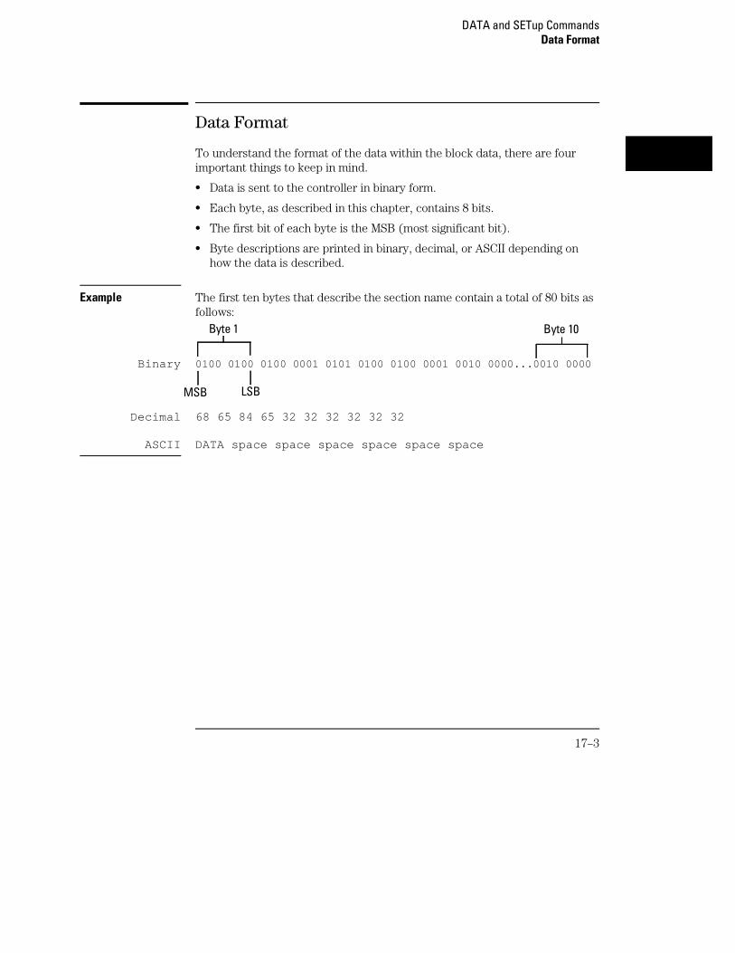
Data Format
To understand the format of the data within the block data, there are fourimportant things to keep in mind.
• Data is sent to the controller in binary form.
• Each byte, as described in this chapter, contains 8 bits.
• The first bit of each byte is the MSB (most significant bit).
• Byte descriptions are printed in binary, decimal, or ASCII depending onhow the data is described.
Example The first ten bytes that describe the section name contain a total of 80 bits asfollows:
Binary 0100 0100 0100 0001 0101 0100 0100 0001 0010 0000...0010 0000
Decimal 68 65 84 65 32 32 32 32 32 32
ASCII DATA space space space space space space
Byte 10Byte 1
MSB LSB
DATA and SETup CommandsData Format
17–3
SYSTem:DATA
Command :SYSTem:DATA <block data>
The SYSTem:DATA command transmits the acquisition memory data fromthe controller to the 16557D logic analyzer.
The block data consists of a variable number of bytes containing informationcaptured by the acquisition chips. Since no parameter checking isperformed, out-of-range values could cause instrument lockup; therefore,care should be taken when transferring the data string into the 16557D.
The <block data> parameter can be broken down into a <block lengthspecifier> and a variable number of <section> s.
The <block length specifier> always takes the form #8DDDDDDDD. EachD represents a digit (ASCII characters "0" through "9"). The value of the eightdigits represents the total length of the block (all sections). For example, ifthe total length of the block is 14522 bytes, the block length specifier wouldbe "#800014522 ".
Each <section> consists of a <section header> and <section data> .The <section data> format varies for each section and may be any length.For the DATA instruction, there is only one <section> , which is composedof a data preamble followed by the acquisition data. This section has avariable number of bytes depending on configuration and amount of acquireddata.
Example OUTPUT XXX;":SYSTEM:DATA" <block data>
Do not load UNPacked data into the instrument; it may cause the AgilentTechnologies 16500 to lock up. If this happens, cycle power. Only data saved inPACKed mode can be reloaded back into a logic analyzer.
DATA and SETup CommandsSYSTem:DATA
17–4
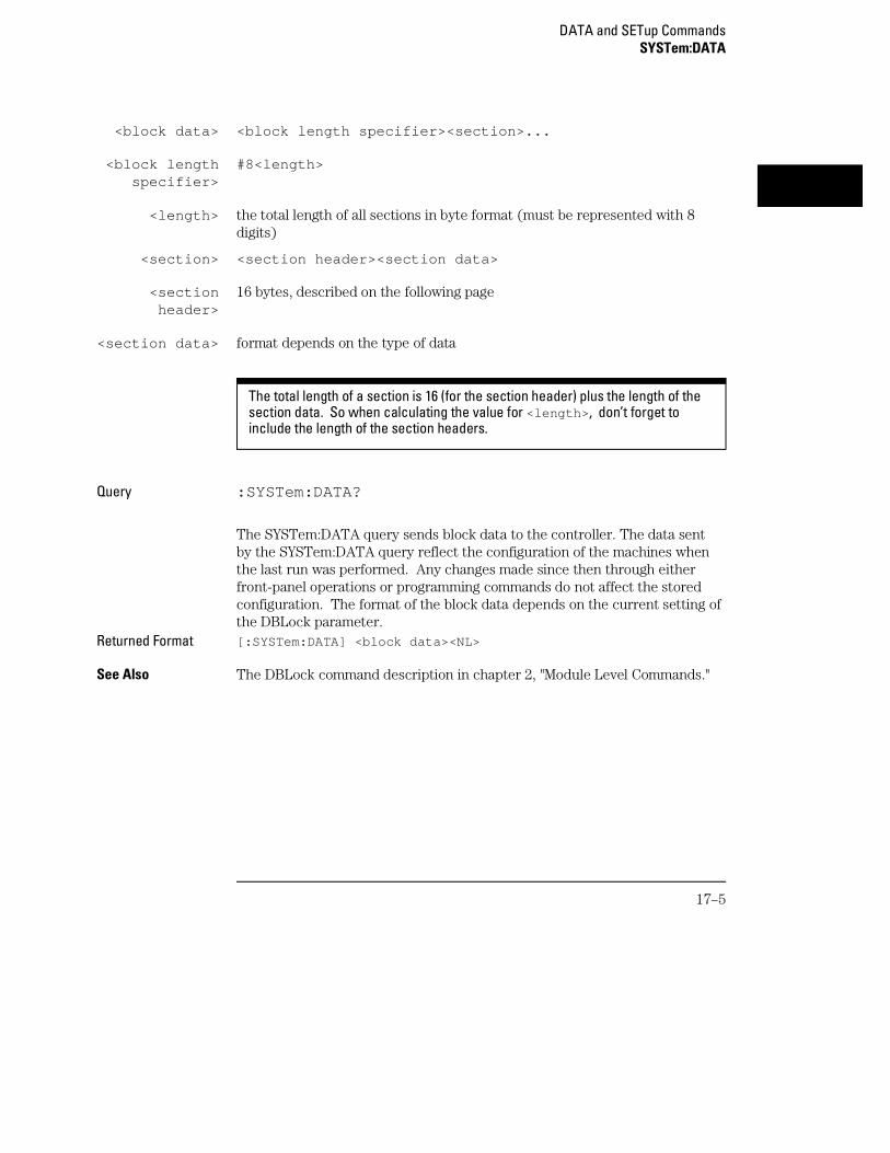
<block data> <block length specifier><section>...
<block lengthspecifier>
#8<length>
<length> the total length of all sections in byte format (must be represented with 8digits)
<section> <section header><section data>
<sectionheader>
16 bytes, described on the following page
<section data> format depends on the type of data
The total length of a section is 16 (for the section header) plus the length of thesection data. So when calculating the value for <length> , don’t forget toinclude the length of the section headers.
Query :SYSTem:DATA?
The SYSTem:DATA query sends block data to the controller. The data sentby the SYSTem:DATA query reflect the configuration of the machines whenthe last run was performed. Any changes made since then through eitherfront-panel operations or programming commands do not affect the storedconfiguration. The format of the block data depends on the current setting ofthe DBLock parameter.
Returned Format [:SYSTem:DATA] <block data><NL>
See Also The DBLock command description in chapter 2, "Module Level Commands."
DATA and SETup CommandsSYSTem:DATA
17–5
Section Header Description
Because block data may contain multiple sections, this description numbersbytes beginning at the section header. The initial 10 bytes of the block lengthspecifier and any other sections are not included in the numbering.
The section header uses bytes 1 through 16 (this manual begins counting at1; there is no byte 0). The 16 bytes of the section header are as follows:
Byte Position
1 10 bytes - Section name ("DATA space space space space spacespace" in ASCII for the DATA instruction).
11 1 byte - Reserved
12 1 byte - Module ID (34 decimal for the 16557D master card, and 35 forexpander cards)
13 4 bytes - Length of block in bytes that when converted to decimal, specifiesthe number of bytes contained in the data block.
Section Data
For the SYSTem:DATA query when DBLock mode is UNPacked, the<section data> parameter consists of two parts: the data preamble and theacquisition data. These are described in the following two sections.
When DBLock mode is set to PACKed, the format is highly configurationdependent. Because of the complexity and because it may be changedwithout notice, it is not described here.
Use UNPacked format for data you wish to post-process, and PACKed datafor measurements you may want to load back into the analyzer module later.
DATA and SETup CommandsSection Header Description
17–6
Data Preamble Description
The UNPacked block data is organized as 574 bytes of preamble information,followed by a variable number of bytes of data. The preamble givesinformation for each analyzer describing the amount and type of datacaptured, where the trace point occurred in the data, which pods areassigned to which analyzer, and other information.
The preamble (bytes 17 through 590) consists of the following 574 bytes:
Byte Position
17 4 bytes - Instrument ID (always 16500 decimal)
21 4 bytes - Revision Code
25 4 bytes - number of pod pairs used in last acquisition
29 4 bytes - Analyzer ID (1 for 16557D)
The values stored in the preamble represent the captured data stored in thisstructure and not the current analyzer configuration. For example, the modeof the data (bytes 33 and 103) may be STATE with tagging, while the currentsetup of the analyzer is TIMING.
The next 70 bytes are for Analyzer 1 Data Information.
33 4 bytes - Analyzer 1 data mode, one of the following decimal values:−1 = off0 = State data, no tags1 = State data with tags2 = State data with tags10 = conventional timing data on all channels13 = conventional timing data on half channels
State data includes data acquired by State Compare and SPA machine types.There is no change in the data format.
DATA and SETup CommandsData Preamble Description
17–7
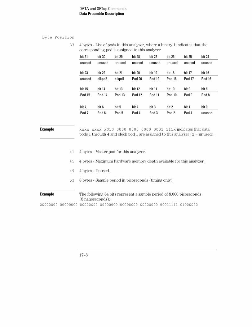
Byte Position
37 4 bytes - List of pods in this analyzer, where a binary 1 indicates that thecorresponding pod is assigned to this analyzer
bit 31 bit 30 bit 29 bit 28 bit 27 bit 26 bit 25 bit 24
unused unused unused unused unused unused unused unused
bit 23 bit 22 bit 21 bit 20 bit 19 bit 18 bit 17 bit 16
unused clkpd2 clkpd1 Pod 20 Pod 19 Pod 18 Pod 17 Pod 16
bit 15 bit 14 bit 13 bit 12 bit 11 bit 10 bit 9 bit 8
Pod 15 Pod 14 Pod 13 Pod 12 Pod 11 Pod 10 Pod 9 Pod 8
bit 7 bit 6 bit 5 bit 4 bit 3 bit 2 bit 1 bit 0
Pod 7 Pod 6 Pod 5 Pod 4 Pod 3 Pod 2 Pod 1 unused
Example xxxx xxxx x010 0000 0000 0000 0001 111x indicates that datapods 1 through 4 and clock pod 1 are assigned to this analyzer (x = unused).
41 4 bytes - Master pod for this analyzer.
45 4 bytes - Maximum hardware memory depth available for this analyzer.
49 4 bytes - Unused.
53 8 bytes - Sample period in picoseconds (timing only).
Example The following 64 bits represent a sample period of 8,000 picoseconds(8 nanoseconds):
00000000 00000000 00000000 00000000 00000000 00000000 00011111 01000000
DATA and SETup CommandsData Preamble Description
17–8
Byte Position
61 4 bytes - Tag type for state mode in one of the following decimal values:0 = off1 = time tags2 = state tags
65 8 bytes - Trigger offset. The time offset (in picoseconds) from when thisanalyzer is triggered and when this analyzer provides an output trigger to theIMB or port out. The value for one analyzer is always zero and the value forthe other analyzer is the time between the triggers of the two analyzers.
73 30 bytes - Unused
103 70 bytes - The next 70 bytes are for Analyzer 2 Data Information. They areorganized in the same manner as Analyzer 1 above, but they occupy bytes103 through 172.
173 88 bytes - Number of valid rows of data (starting at byte 591) for each pod.
The 26 bytes of this group are organized as follows:
Bytes 173 through 180 Unused
Bytes 181 through 184 contain the number of valid rows of data forpod 4 (most significant pod) of the highest slot expansion card in afive-card module.
Bytes 185 through 188 contain the number of valid rows of data forpod 3 of the highest slot expansion card in a five-card module.
Bytes 189 through 192 contain the number of valid rows of data forpod 2 of the highest slot expansion card in a five-card module.
Bytes 193 through 196 contain the number of valid rows of data forpod 1 (least significant pod) of the highest slot expansion card in afive-card module.
Bytes 197 through 200 contain the number of valid rows of data forpod 4 (most significant pod) of either the highest slot expansion card in afour-card module, or a middle card expansion card in a five-card module.
Bytes 201 through 204 contain the number of valid rows of data forpod 3 of either the highest slot expansion card in a four-card module, ora middle card expansion card in a five-card module.
DATA and SETup CommandsData Preamble Description
17–9
Byte Position Bytes 205 through 208 contain the number of valid rows of data forpod 2 of either the highest slot expansion card in a four-card module, ora middle card expansion card in a five-card module.
Bytes 209 through 212 contain the number of valid rows of data forpod 1 (least significant pod) of either the highest slot expansion card in afour-card module, or a middle slot expansion card in a five-card module.
Bytes 213 through 216 contain the number of valid rows of data forpod 4 (most significant pod) of either the highest slot expansion card in athree-card module, or a middle slot expansion card in a four- or five-cardmodule.
Bytes 217 through 220 contain the number of valid rows of data forpod 3 of either the highest slot expansion card in a three-card module, ora middle expansion card in a four- or five-card module.
Bytes 221 through 224 contain the number of valid rows of data forpod 2 of either the highest slot expansion card in a three-card module, ora middle card expansion card in a four- or five-card module.
Bytes 225 through 228 contain the number of valid rows of data forpod 1 (least significant pod) of either the highest expansion card in athree-card module, or a middle expansion card in a four- or five-cardmodule.
Bytes 229 through 232 contain the number of valid rows of data forpod 4 (most significant pod) of either the expansion card in a two-cardmodule, or a middle expansion card in a three-, four-, or five-card module.
Bytes 233 through 236 contain the number of valid rows of data forpod 3 of either the expansion card in a two-card module, or a middleexpansion card in a three-, four-, or five-card module.
Bytes 237 through 240 contain the number of valid rows of data forpod 2 of either the expansion card in a two-card module, or a middleexpansion card in a three-, four-, or five-card module.
Bytes 241 through 244 contain the number of valid rows of data forpod 1 (least significant pod) of either the expansion card in a two-cardmodule, or a middle expansion card in a three-, four-, or five-card module.
Bytes 245 through 248 contain the number of valid rows of data forpod 4 (least significant pod) of the master card.
DATA and SETup CommandsData Preamble Description
17–10
Byte Position Bytes 249 through 252 contain the number of valid rows of data forpod 3 of the master card.
Bytes 253 through 256 contain the number of valid rows of data forpod 2 of the master card.
Bytes 257 through 260 contain the number of valid rows of data forpod 1 (least significant pod) of the master card.
261 88 bytes - The trigger point location for each pod. This byte group isorganized in the same way as the data rows (starting at byte 173 above).These numbers are base-zero numbers which start from the first samplestored for a specific pod. Bytes 345-348 contain the trigger location for pod 1.
Example If bytes 341 and 344 contain the value 101008, the data in row 101008 forthat pod is the trigger. There are 101008 rows of pre-trigger data as shownbelow.
row 0row 1
.row 101007row 101008 – trigger pointrow 101009
349 234 bytes - Unused
583 2 bytes - Real Time Clock (RTC) year at time of acquisition. Year value isequal to the year minus 1990.
585 2 bytes - RTC month (1 = January . . . 12 = December ) at time of acquisition.
586 1 byte - RTC day of the month at time of acquisition.
587 1 byte - RTC day of the week at time of acquisition.
588 1 byte - RTC hour (0 through 23) at time of acquisition.
589 1 byte - RTC minutes at time of acquisition.
590 1 byte - RTC seconds at time of acquisition.
DATA and SETup CommandsData Preamble Description
17–11
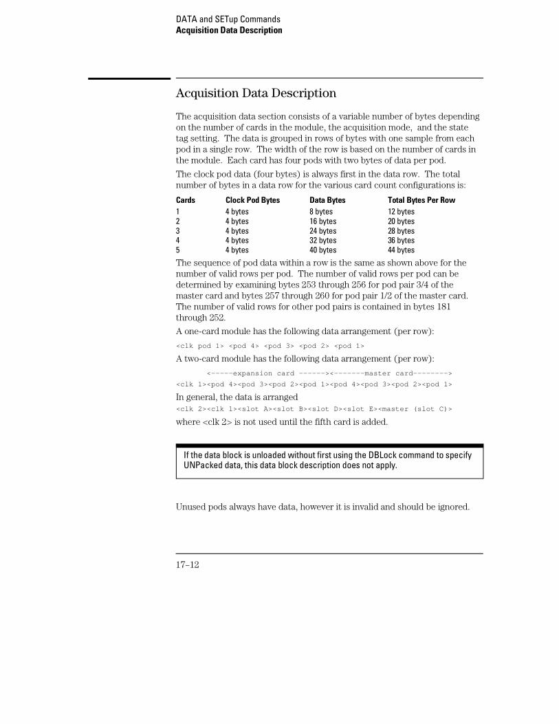
Acquisition Data Description
The acquisition data section consists of a variable number of bytes dependingon the number of cards in the module, the acquisition mode, and the statetag setting. The data is grouped in rows of bytes with one sample from eachpod in a single row. The width of the row is based on the number of cards inthe module. Each card has four pods with two bytes of data per pod.
The clock pod data (four bytes) is always first in the data row. The totalnumber of bytes in a data row for the various card count configurations is:
Cards Clock Pod Bytes Data Bytes Total Bytes Per Row1 4 bytes 8 bytes 12 bytes2 4 bytes 16 bytes 20 bytes3 4 bytes 24 bytes 28 bytes4 4 bytes 32 bytes 36 bytes 5 4 bytes 40 bytes 44 bytes
The sequence of pod data within a row is the same as shown above for thenumber of valid rows per pod. The number of valid rows per pod can bedetermined by examining bytes 253 through 256 for pod pair 3/4 of themaster card and bytes 257 through 260 for pod pair 1/2 of the master card.The number of valid rows for other pod pairs is contained in bytes 181through 252.
A one-card module has the following data arrangement (per row):
<clk pod 1> <pod 4> <pod 3> <pod 2> <pod 1>
A two-card module has the following data arrangement (per row):
<-----expansion card ------><-------master card-------->
<clk 1><pod 4><pod 3><pod 2><pod 1><pod 4><pod 3><pod 2><pod 1>
In general, the data is arranged<clk 2><clk 1><slot A><slot B><slot D><slot E><master (slot C)>
where <clk 2> is not used until the fifth card is added.
If the data block is unloaded without first using the DBLock command to specifyUNPacked data, this data block description does not apply.
Unused pods always have data, however it is invalid and should be ignored.
DATA and SETup CommandsAcquisition Data Description
17–12
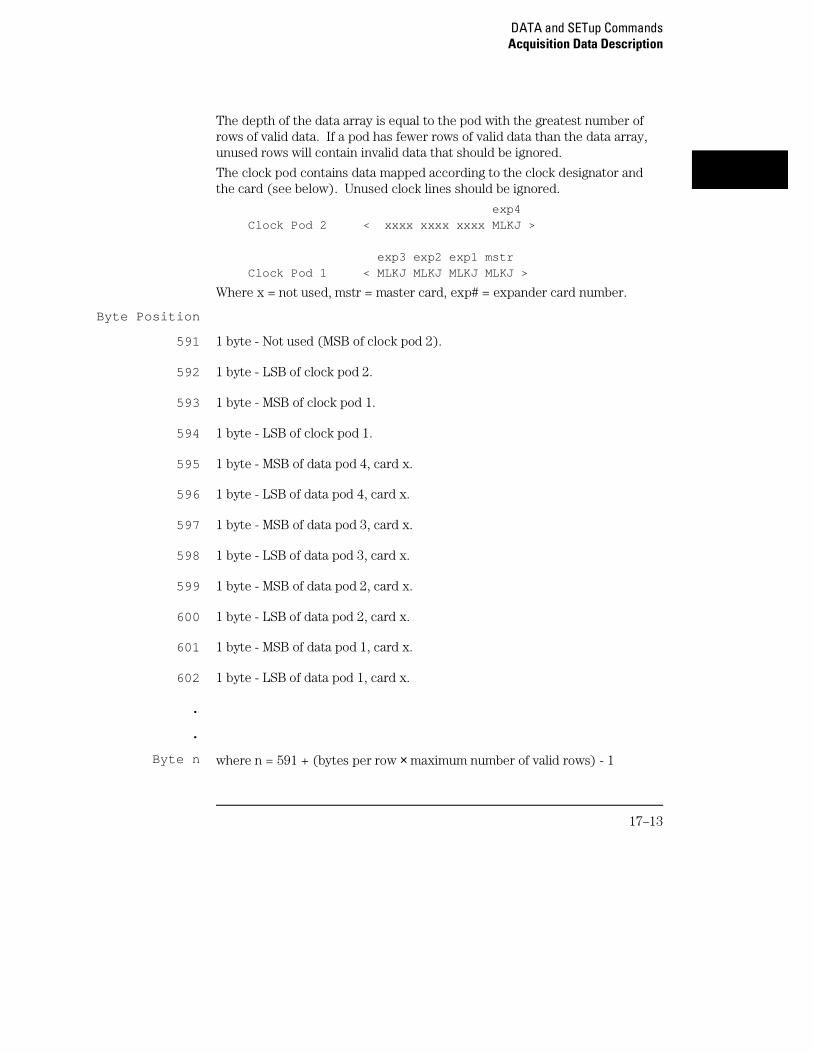
The depth of the data array is equal to the pod with the greatest number ofrows of valid data. If a pod has fewer rows of valid data than the data array,unused rows will contain invalid data that should be ignored.
The clock pod contains data mapped according to the clock designator andthe card (see below). Unused clock lines should be ignored.
exp4Clock Pod 2 < xxxx xxxx xxxx MLKJ >
exp3 exp2 exp1 mstrClock Pod 1 < MLKJ MLKJ MLKJ MLKJ >
Where x = not used, mstr = master card, exp# = expander card number.
Byte Position
591 1 byte - Not used (MSB of clock pod 2).
592 1 byte - LSB of clock pod 2.
593 1 byte - MSB of clock pod 1.
594 1 byte - LSB of clock pod 1.
595 1 byte - MSB of data pod 4, card x.
596 1 byte - LSB of data pod 4, card x.
597 1 byte - MSB of data pod 3, card x.
598 1 byte - LSB of data pod 3, card x.
599 1 byte - MSB of data pod 2, card x.
600 1 byte - LSB of data pod 2, card x.
601 1 byte - MSB of data pod 1, card x.
602 1 byte - LSB of data pod 1, card x.
.
.
Byte n where n = 591 + (bytes per row × maximum number of valid rows) - 1
DATA and SETup CommandsAcquisition Data Description
17–13
Example A three-card configuration with 516096 valid rows
First data byte = byte 591
Last data byte = 14,451,278 [591 + (28 × 516096) - 1]
Time Tag Data Description
If tags are enabled for one or both analyzers, the tag data follows theacquisition data. The first byte of the tag data is determined as follows:
591 + (bytes per row × maximum number of valid rows)
Each row of the tag data array consists of one (single analyzer with state ortime tags) or two (both analyzers with tags) eight-byte tag values per row.When both analyzers have state tags enabled, the first tag value in a rowbelongs to Machine 1 and the second tag value belongs to Machine 2.
If the tag value is a time tag, the number is an integer representing time inpicoseconds. If the tag value is a state tag, the number is an integer statecount.
The total size of the tag array is 8 or 16 bytes per row times the greatestnumber of valid rows.
SYSTem:SETup
Command :SYStem:SETup <block data>
The SYStem:SETup command configures the logic analyzer module asdefined by the block data sent by the controller. It is not affected by DBLock.
There are three data sections which are always returned. The strings whichare included in the section header are:
"CONFIG ""DISPLAY1 ""BIG_ATTRIB"
DATA and SETup CommandsTime Tag Data Description
17–14
Additionally, the following sections may also be included, depending on whatis available:
"SYMBOLS A ""SYMBOLS B ""INVASM A ""INVASM B "
<block data> <block length specifier><section>...
<block lengthspecifier>
#8<length>
<length> the total length of all sections in byte format (must be represented with 8digits)
<section> <section header><section data>
<sectionheader>
16 bytes in the following format:10 bytes for the section name1 byte reserved1 byte for the module ID code (34 for the 16557D logic analyzer)4 bytes for the length of the section data in bytes
<section data> format depends on the type of data. The total length of a section is 16 (forthe section header) plus the length of the section data. So when calculatingthe value for <length> , don’t forget to include the length of the sectionheaders. The format of the setup block is not affected by the DBLockcommand setting.
Example OUTPUT XXX;"SETUP" <block data>
Query :SYStem:SETup?
The SYStem:SETup query returns a block of data that contains the currentconfiguration to the controller.
Returned Format [:SYStem:SETup] <block data><NL>
DATA and SETup CommandsSYSTem:SETup
17–15

17–16
Part 3
18 Programming Examples
Programming Examples

18
Programming Examples
Introduction
This chapter contains short, usable, and tested programs that coverthe most asked for examples. The examples are written in HP BASIC6.0.
• Making a timing analyzer measurement
• Making a state analyzer measurement
• Making a state compare analyzer measurement
• Transferring logic analyzer configuration between the logic analyzerand the controller
• Checking for measurement completion
• Sending queries to the logic analyzer
18–2
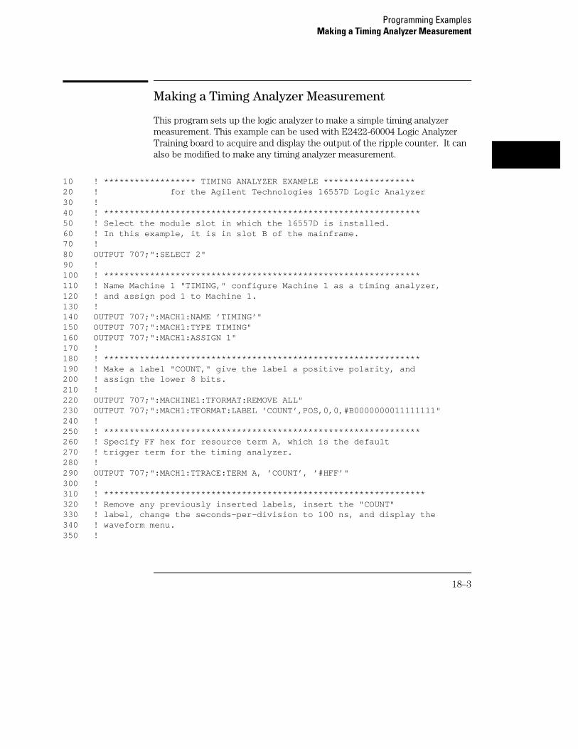
Making a Timing Analyzer Measurement
This program sets up the logic analyzer to make a simple timing analyzermeasurement. This example can be used with E2422-60004 Logic AnalyzerTraining board to acquire and display the output of the ripple counter. It canalso be modified to make any timing analyzer measurement.
10 ! ****************** TIMING ANALYZER EXAMPLE ******************20 ! for the Agilent Technologies 16557D Logic Analyzer30 !40 ! **************************************************************50 ! Select the module slot in which the 16557D is installed. 60 ! In this example, it is in slot B of the mainframe.70 !80 OUTPUT 707;":SELECT 2"90 !100 ! **************************************************************110 ! Name Machine 1 "TIMING," configure Machine 1 as a timing analyzer,120 ! and assign pod 1 to Machine 1.130 !140 OUTPUT 707;":MACH1:NAME ’TIMING’"150 OUTPUT 707;":MACH1:TYPE TIMING"160 OUTPUT 707;":MACH1:ASSIGN 1"170 !180 ! **************************************************************190 ! Make a label "COUNT," give the label a positive polarity, and200 ! assign the lower 8 bits.210 !220 OUTPUT 707;":MACHINE1:TFORMAT:REMOVE ALL"230 OUTPUT 707;":MACH1:TFORMAT:LABEL ’COUNT’,POS,0,0,#B0000000011111111"240 !250 ! **************************************************************260 ! Specify FF hex for resource term A, which is the default 270 ! trigger term for the timing analyzer.280 !290 OUTPUT 707;":MACH1:TTRACE:TERM A, ’COUNT’, ’#HFF’"300 !310 ! ***************************************************************320 ! Remove any previously inserted labels, insert the "COUNT"330 ! label, change the seconds-per-division to 100 ns, and display the340 ! waveform menu.350 !
Programming ExamplesMaking a Timing Analyzer Measurement
18–3
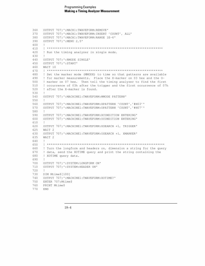
360 OUTPUT 707;":MACH1:TWAVEFORM:REMOVE"370 OUTPUT 707;":MACH1:TWAVEFORM:INSERT ’COUNT’, ALL"380 OUTPUT 707;":MACH1:TWAVEFORM:RANGE 1E-6"390 OUTPUT 707;":MENU 2,5"400 !410 ! ****************************************************************420 ! Run the timing analyzer in single mode.430 !440 OUTPUT 707;":RMODE SINGLE"450 OUTPUT 707;":START"460 WAIT 10470 ! ****************************************************************480 ! Set the marker mode (MMODE) to time so that patterns are available490 ! for marker measurements. Place the X-marker on 03 hex and the O-500 ! marker on 07 hex. Then tell the timing analyzer to find the first510 ! occurrence of 03h after the trigger and the first occurrence of 07h520 ! after the X-marker is found.530 !540 OUTPUT 707;":MACHINE1:TWAVEFORM:MMODE PATTERN"550 !560 OUTPUT 707;":MACHINE1:TWAVEFORM:XPATTERN ’COUNT’,’#H03’"570 OUTPUT 707;":MACHINE1:TWAVEFORM:OPATTERN ’COUNT’,’#H07’"580 !590 OUTPUT 707;":MACHINE1:TWAVEFORM:XCONDITION ENTERING"600 OUTPUT 707;":MACHINE1:TWAVEFORM:OCONDITION ENTERING"610 !620 OUTPUT 707;":MACHINE1:TWAVEFORM:XSEARCH +1, TRIGGER"625 WAIT 2630 OUTPUT 707;":MACHINE1:TWAVEFORM:OSEARCH +1, XMARKER"635 WAIT 2640 !650 ! *****************************************************************660 ! Turn the longform and headers on, dimension a string for the query670 ! data, send the XOTIME query and print the string containing the680 ! XOTIME query data.690 !700 OUTPUT 707;":SYSTEM:LONGFORM ON"710 OUTPUT 707;":SYSTEM:HEADER ON"720 !730 DIM Mtime$[100]740 OUTPUT 707;":MACHINE1:TWAVEFORM:XOTIME?"750 ENTER 707;Mtime$760 PRINT Mtime$770 END
Programming ExamplesMaking a Timing Analyzer Measurement
18–4
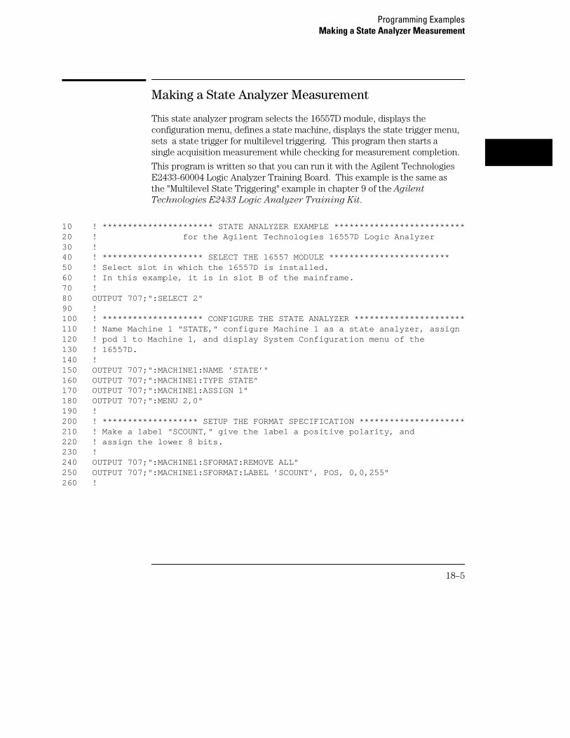
Making a State Analyzer Measurement
This state analyzer program selects the 16557D module, displays theconfiguration menu, defines a state machine, displays the state trigger menu,sets a state trigger for multilevel triggering. This program then starts asingle acquisition measurement while checking for measurement completion.
This program is written so that you can run it with the Agilent TechnologiesE2433-60004 Logic Analyzer Training Board. This example is the same asthe "Multilevel State Triggering" example in chapter 9 of the Agilent
Technologies E2433 Logic Analyzer Training Kit.
10 ! ********************** STATE ANALYZER EXAMPLE **************************20 ! for the Agilent Technologies 16557D Logic Analyzer30 !40 ! ******************** SELECT THE 16557 MODULE ************************50 ! Select slot in which the 16557D is installed. 60 ! In this example, it is in slot B of the mainframe.70 !80 OUTPUT 707;":SELECT 2"90 !100 ! ******************** CONFIGURE THE STATE ANALYZER **********************110 ! Name Machine 1 "STATE," configure Machine 1 as a state analyzer, assign120 ! pod 1 to Machine 1, and display System Configuration menu of the130 ! 16557D.140 !150 OUTPUT 707;":MACHINE1:NAME ’STATE’"160 OUTPUT 707;":MACHINE1:TYPE STATE"170 OUTPUT 707;":MACHINE1:ASSIGN 1"180 OUTPUT 707;":MENU 2,0"190 !200 ! ******************* SETUP THE FORMAT SPECIFICATION *********************210 ! Make a label "SCOUNT," give the label a positive polarity, and220 ! assign the lower 8 bits.230 !240 OUTPUT 707;":MACHINE1:SFORMAT:REMOVE ALL"250 OUTPUT 707;":MACHINE1:SFORMAT:LABEL ’SCOUNT’, POS, 0,0,255"260 !
Programming ExamplesMaking a State Analyzer Measurement
18–5
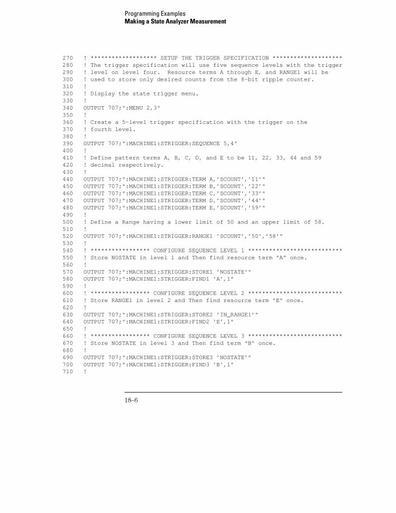
270 ! ******************* SETUP THE TRIGGER SPECIFICATION ********************280 ! The trigger specification will use five sequence levels with the trigger290 ! level on level four. Resource terms A through E, and RANGE1 will be300 ! used to store only desired counts from the 8-bit ripple counter.310 !320 ! Display the state trigger menu.330 !340 OUTPUT 707;":MENU 2,3"350 !360 ! Create a 5-level trigger specification with the trigger on the370 ! fourth level.380 !390 OUTPUT 707;":MACHINE1:STRIGGER:SEQUENCE 5,4"400 !410 ! Define pattern terms A, B, C, D, and E to be 11, 22, 33, 44 and 59420 ! decimal respectively.430 !440 OUTPUT 707;":MACHINE1:STRIGGER:TERM A,’SCOUNT’,’11’"450 OUTPUT 707;":MACHINE1:STRIGGER:TERM B,’SCOUNT’,’22’"460 OUTPUT 707;":MACHINE1:STRIGGER:TERM C,’SCOUNT’,’33’"470 OUTPUT 707;":MACHINE1:STRIGGER:TERM D,’SCOUNT’,’44’"480 OUTPUT 707;":MACHINE1:STRIGGER:TERM E,’SCOUNT’,’59’"490 !500 ! Define a Range having a lower limit of 50 and an upper limit of 58.510 !520 OUTPUT 707;":MACHINE1:STRIGGER:RANGE1 ’SCOUNT’,’50’,’58’"530 !540 ! ***************** CONFIGURE SEQUENCE LEVEL 1 ***************************550 ! Store NOSTATE in level 1 and Then find resource term "A" once.560 !570 OUTPUT 707;":MACHINE1:STRIGGER:STORE1 ’NOSTATE’"580 OUTPUT 707;":MACHINE1:STRIGGER:FIND1 ’A’,1"590 !600 ! ***************** CONFIGURE SEQUENCE LEVEL 2 ***************************610 ! Store RANGE1 in level 2 and Then find resource term "E" once.620 !630 OUTPUT 707;":MACHINE1:STRIGGER:STORE2 ’IN_RANGE1’"640 OUTPUT 707;":MACHINE1:STRIGGER:FIND2 ’E’,1"650 !660 ! ***************** CONFIGURE SEQUENCE LEVEL 3 ***************************670 ! Store NOSTATE in level 3 and Then find term "B" once.680 !690 OUTPUT 707;":MACHINE1:STRIGGER:STORE3 ’NOSTATE’"700 OUTPUT 707;":MACHINE1:STRIGGER:FIND3 ’B’,1"710 !
Programming ExamplesMaking a State Analyzer Measurement
18–6
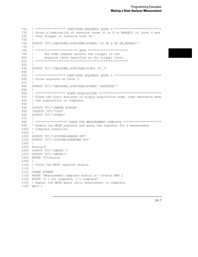
720 ! ***************** CONFIGURE SEQUENCE LEVEL 4 ***************************730 ! Store a combination of resource terms (C or D or RANGE1) in level 4 and740 ! Then Trigger on resource term "E."750 !760 OUTPUT 707;":MACHINE1:STRIGGER:STORE4 ’(C OR D OR IN_RANGE1)’"770 !780 ! ************************ NOTE ***********************790 ! The FIND command selects the trigger in the800 ! sequence level specified as the trigger level.810 ! *****************************************************820 !830 OUTPUT 707;":MACHINE1:STRIGGER:FIND4 ’E’,1"840 !850 ! ***************** CONFIGURE SEQUENCE LEVEL 5 ***************************860 ! Store anystate on level 5870 !880 OUTPUT 707;":MACHINE1:STRIGGER:STORE5 ’ANYSTATE’"890 !900 ! ***************** START ACQUISITION ************************************910 ! Place the logic analyzer in single acquisition mode, then determine when920 ! the acquisition is complete.930 !940 OUTPUT 707;":RMODE SINGLE"950 !OUTPUT 707;"*CLS"960 OUTPUT 707;":START"970 !980 ! ****************** CHECK FOR MEASUREMENT COMPLETE **********************990 ! Enable the MESR register and query the register for a measurement1000 ! complete condition.1010 !1020 OUTPUT 707;":SYSTEM:HEADER OFF"1030 OUTPUT 707;":SYSTEM:LONGFORM OFF"1040 !1050 Status=01060 OUTPUT 707;":MESE2 1"1070 OUTPUT 707;":MESR2?"1080 ENTER 707;Status1090 !1100 ! Print the MESR register status.1110 !1120 CLEAR SCREEN1130 PRINT "Measurement complete status is ";Status AND 11140 PRINT "0 = not complete, 1 = complete"1150 ! Repeat the MESR query until measurement is complete.1160 WAIT 1
Programming ExamplesMaking a State Analyzer Measurement
18–7
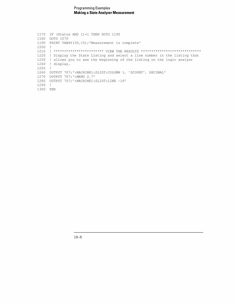
1170 IF (Status AND 1)=1 THEN GOTO 11901180 GOTO 10701190 PRINT TABXY(30,15);"Measurement is complete"1200 !1210 ! ************************ VIEW THE RESULTS *****************************1220 ! Display the State Listing and select a line number in the listing that1230 ! allows you to see the beginning of the listing on the logic analyer1240 ! display.1250 !1260 OUTPUT 707;":MACHINE1:SLIST:COLUMN 1, ’SCOUNT’, DECIMAL"1270 OUTPUT 707;":MENU 2,7"1280 OUTPUT 707;":MACHINE1:SLIST:LINE -16"1290 !1300 END
Programming ExamplesMaking a State Analyzer Measurement
18–8
Making a State Compare Analyzer Measurement
This program example acquires a state listing, copies the listing to thecompare listing, acquires another state listing, and compares both listings tofind differences.
This program is written so that you can run it with the Agilent TechnologiesE2433-60004 Logic Analyzer Training Board. This example is the same asthe "State Compare" example in chapter 3 of the Agilent Technologies
E2433 Logic Analyzer Training Kit.
10 ! *********** STATE COMPARE EXAMPLE ********************************20 ! for the Agilent Technologies 16557D Logic Analyzer30 !40 !50 !***************** SELECT THE 16557D MODULE *********************60 ! Select the slot in which the module is installed. 70 ! In this example, it is in slot B of the mainframe.80 !90 OUTPUT 707;":SELECT 2"100 !110 !************** CONFIGURE THE STATE ANALYZER ***********************120 ! Name Machine 1 "STATE," configure Machine 1 as a compare state 130 ! analyzer, and assign pod 1 to Machine 1.140 !150 OUTPUT 707;":MACHINE1:NAME ’STATE’"160 OUTPUT 707;":MACHINE1:TYPE COMPARE"170 OUTPUT 707;":MACHINE1:ASSIGN 1"180 !190 ! ******************************************************************200 ! Remove all labels previously set up, make a label "SCOUNT," specify210 ! positive logic, and assign the lower 8 bits of pod 1 to the label.220 !230 OUTPUT 707;":MACHINE1:SFORMAT:REMOVE ALL"240 OUTPUT 707;":MACHINE1:SFORMAT:LABEL ’SCOUNT’, POS, 0,0,255"250 !260 ! ******************************************************************270 ! Make the "J" clock the Master clock and specify the falling edge.280 !290 OUTPUT 707;":MACHINE1:SFORMAT:MASTER J, FALLING"300 !
Programming ExamplesMaking a State Compare Analyzer Measurement
18–9
310 ! ******************************************************************320 ! Specify two sequence levels, the trigger sequence level, specify330 ! FF hex for the "a" term which will be the trigger term, and store340 ! no states until the trigger is found.350 !360 OUTPUT 707;":MACHINE1:STRIGGER:SEQUENCE 2,1"370 OUTPUT 707;":MACHINE1:STRIGGER:TERM A,’SCOUNT’,’#HFF’"380 OUTPUT 707;":MACHINE1:STRIGGER:STORE1 ’NOSTATE’"390 OUTPUT 707;":MENU 2,3"400 !410 ! ******************************************************************420 ! Change the displayed menu to the state listing and start the state430 ! analyzer in repetitive mode.440 !450 OUTPUT 707;":MENU 2,7"460 OUTPUT 707;":RMODE REPETITIVE"470 OUTPUT 707;":START"480 !490 ! ******************************************************************500 ! The logic analyzer is now running in the repetitive mode510 ! and will remain in repetitive until the STOP command is sent.520 !530 PRINT "The logic analyzer is now running in the repetitive mode"540 PRINT "and will remain in repetitive until the STOP command is sent."550 PRINT 560 PRINT "Press CONTINUE"570 PAUSE580 !590 !***********************************************************************600 ! Stop the acquisition and copy the acquired data to the compare reference610 ! listing.620 !630 OUTPUT 707;":STOP"640 OUTPUT 707;":MENU 2,10"650 OUTPUT 707;":MACHINE1:COMPARE:MENU REFERENCE"660 OUTPUT 707;":MACHINE1:COMPARE:COPY"670 !680 ! The logic analyzer acquisition is now stopped, the Compare menu690 ! is displayed, and the data is now in the compare reference700 ! listing.710 !
Programming ExamplesMaking a State Compare Analyzer Measurement
18–10
720 !***********************************************************************730 ! Display line 4090 of the compare listing and start the analyzer740 ! in a repetitive mode.750 !760 OUTPUT 707;":MACHINE1:COMPARE:LINE 4090"770 OUTPUT 707;":START"780 !790 ! Line 4090 of the listing is now displayed at center screen.810 ! In this example, the states are stable. However, in some820 ! cases, the end points of the listing may vary thus causing830 ! a false failure in compare. To eliminate this problem, a840 ! partial compare can be specified to provide predictable end850 ! points of the data.860 !870 PRINT "Press CONTINUE to send the STOP command."880 PAUSE890 OUTPUT 707;":STOP"900 !910 !************************************************************************920 ! The end points of the compare can be fixed to prevent false failures.930 ! In addition, you can use partial compare to compare only sections940 ! of the state listing you are interested in comparing.950 !960 OUTPUT 707;":MACHINE1:COMPARE:RANGE PARTIAL, 0, 508"970 !980 ! The compare range is now from line 0 to +508990 !1000 !************************************************************************1010 ! Change the Glitch jumper settings on the training board so that the1020 ! data changes, reacquire the data and compare which states are different.1030 PRINT "Change the glitch jumper settings on the training board so that "1040 PRINT "the data changes, reacquire the data and compare which states are "1041 PRINT "different."1050 !1060 PRINT "Press CONTINUE when you have finished changing the jumper."1070 !1080 PAUSE1090 !
Programming ExamplesMaking a State Compare Analyzer Measurement
18–11
1100 !************************************************************************1110 ! Start the logic analyzer to acquire new data and then stop it to compare1120 ! the data. When the acquisition is stopped, the Compare Listing Menuwill1130 ! be displayed.1140 !1150 OUTPUT 707;":START"1155 WAIT 21160 OUTPUT 707;":STOP"1170 OUTPUT 707;":MENU 2,10"1180 !1190 !************************************************************************1200 ! Dimension strings in which the compare find query (COMPARE:FIND?)1210 ! enters the line numbers and error numbers.1220 !1230 DIM Line$[20]1240 DIM Error$[4]1250 DIM Comma$[1]1260 !1270 ! ***********************************************************************1280 ! Display the Difference listing.1290 !1300 OUTPUT 707;":MACHINE1:COMPARE:MENU DIFFERENCE"1310 !1320 ! ************************************************************************1330 ! Loop to query all 508 possible errors.1340 !1350 FOR Error=1 TO 5081360 !1370 ! Read the compare differences1380 !1390 OUTPUT 707;":MACHINE1:COMPARE:FIND? " & VAL$(Error)1400 !1410 ! ************************************************************************1420 ! Format the Error$ string data for display on the controller screen.1430 !1440 IF Error>99 THEN GOTO 15801450 IF Error>9 THEN GOTO 15501460 !1470 ENTER 707 USING "#,1A";Error$1480 ENTER 707 USING "#,1A";Comma$1490 ENTER 707 USING "K";Line$1500 Error_return=IVAL(Error$,10)1510 IF Error_return=0 THEN GOTO 18201520 !
Programming ExamplesMaking a State Compare Analyzer Measurement
18–12
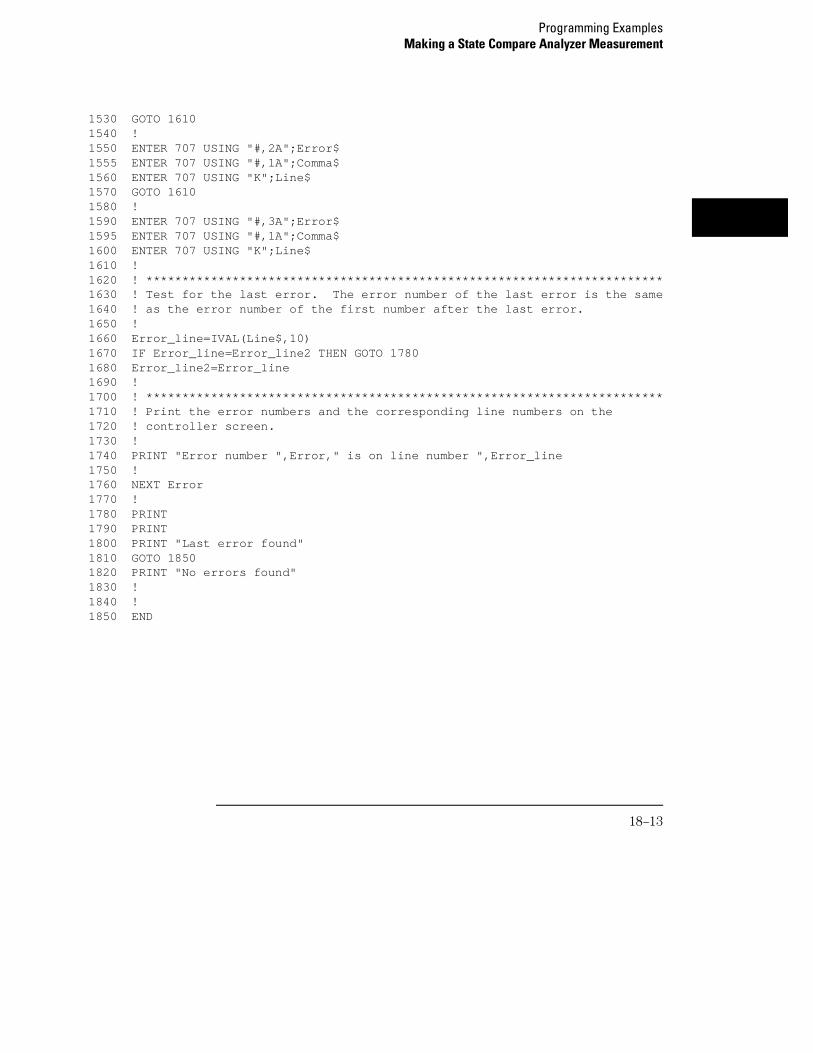
1530 GOTO 16101540 !1550 ENTER 707 USING "#,2A";Error$1555 ENTER 707 USING "#,1A";Comma$1560 ENTER 707 USING "K";Line$1570 GOTO 16101580 !1590 ENTER 707 USING "#,3A";Error$1595 ENTER 707 USING "#,1A";Comma$1600 ENTER 707 USING "K";Line$1610 !1620 ! ************************************************************************1630 ! Test for the last error. The error number of the last error is the same1640 ! as the error number of the first number after the last error.1650 !1660 Error_line=IVAL(Line$,10)1670 IF Error_line=Error_line2 THEN GOTO 17801680 Error_line2=Error_line1690 !1700 ! ************************************************************************1710 ! Print the error numbers and the corresponding line numbers on the1720 ! controller screen.1730 !1740 PRINT "Error number ",Error," is on line number ",Error_line1750 !1760 NEXT Error1770 !1780 PRINT 1790 PRINT 1800 PRINT "Last error found"1810 GOTO 18501820 PRINT "No errors found"1830 !1840 !1850 END
Programming ExamplesMaking a State Compare Analyzer Measurement
18–13
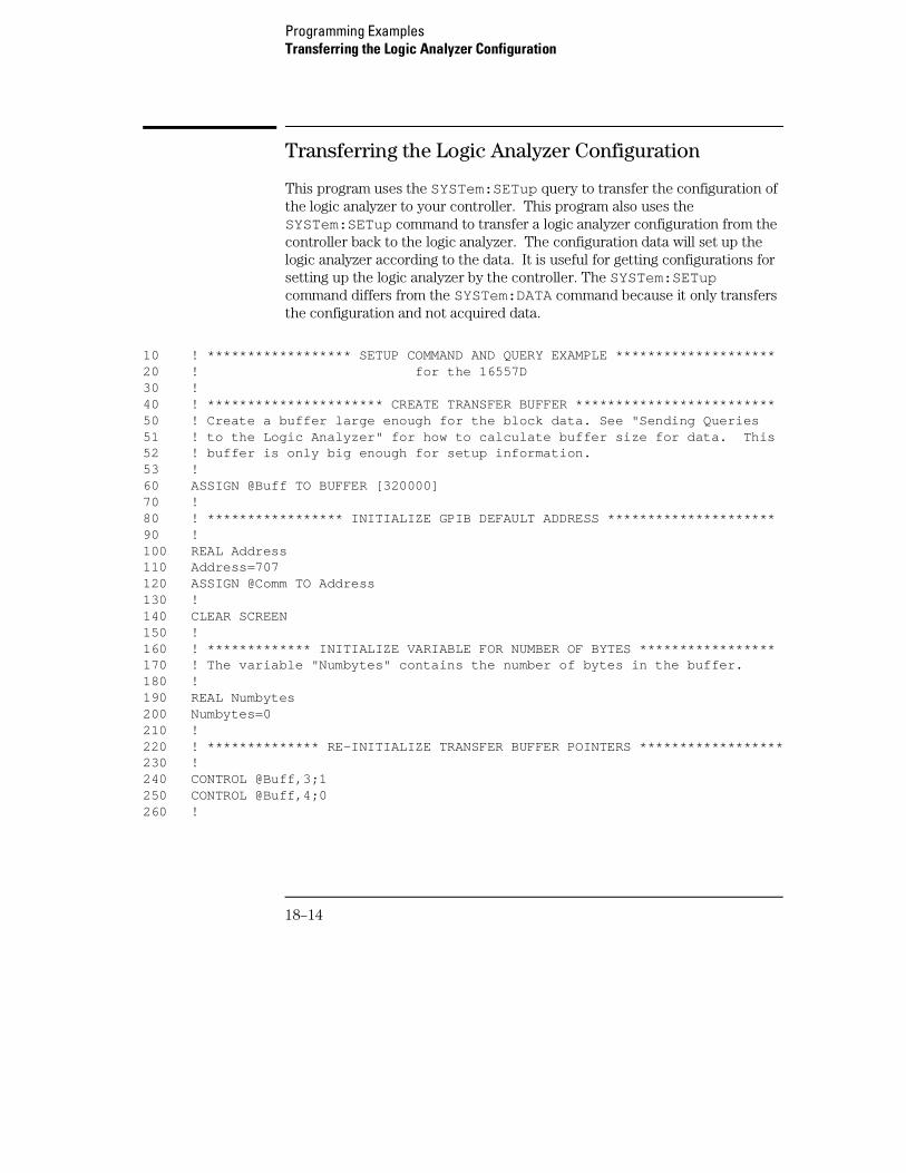
Transferring the Logic Analyzer Configuration
This program uses the SYSTem:SETup query to transfer the configuration ofthe logic analyzer to your controller. This program also uses theSYSTem:SETup command to transfer a logic analyzer configuration from thecontroller back to the logic analyzer. The configuration data will set up thelogic analyzer according to the data. It is useful for getting configurations forsetting up the logic analyzer by the controller. The SYSTem:SETupcommand differs from the SYSTem:DATA command because it only transfersthe configuration and not acquired data.
10 ! ****************** SETUP COMMAND AND QUERY EXAMPLE ********************20 ! for the 16557D30 !40 ! ********************** CREATE TRANSFER BUFFER *************************50 ! Create a buffer large enough for the block data. See "Sending Queries51 ! to the Logic Analyzer" for how to calculate buffer size for data. This52 ! buffer is only big enough for setup information.53 !60 ASSIGN @Buff TO BUFFER [320000]70 !80 ! ***************** INITIALIZE GPIB DEFAULT ADDRESS *********************90 !100 REAL Address110 Address=707120 ASSIGN @Comm TO Address130 !140 CLEAR SCREEN150 !160 ! ************* INITIALIZE VARIABLE FOR NUMBER OF BYTES *****************170 ! The variable "Numbytes" contains the number of bytes in the buffer.180 !190 REAL Numbytes200 Numbytes=0210 !220 ! ************** RE-INITIALIZE TRANSFER BUFFER POINTERS ******************230 !240 CONTROL @Buff,3;1250 CONTROL @Buff,4;0260 !
Programming ExamplesTransferring the Logic Analyzer Configuration
18–14
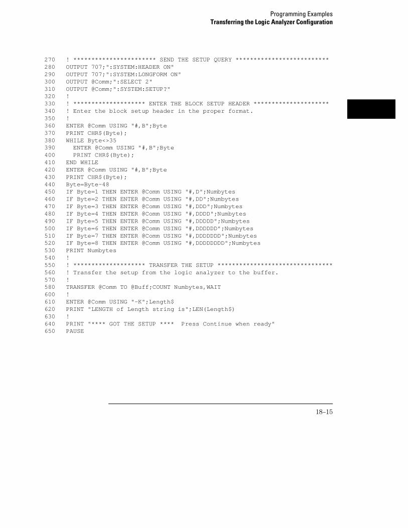
270 ! *********************** SEND THE SETUP QUERY **************************280 OUTPUT 707;":SYSTEM:HEADER ON"290 OUTPUT 707;":SYSTEM:LONGFORM ON"300 OUTPUT @Comm;":SELECT 2"310 OUTPUT @Comm;":SYSTEM:SETUP?"320 !330 ! ******************** ENTER THE BLOCK SETUP HEADER *********************340 ! Enter the block setup header in the proper format.350 !360 ENTER @Comm USING "#,B";Byte370 PRINT CHR$(Byte);380 WHILE Byte<>35390 ENTER @Comm USING "#,B";Byte400 PRINT CHR$(Byte);410 END WHILE420 ENTER @Comm USING "#,B";Byte430 PRINT CHR$(Byte);440 Byte=Byte-48450 IF Byte=1 THEN ENTER @Comm USING "#,D";Numbytes460 IF Byte=2 THEN ENTER @Comm USING "#,DD";Numbytes470 IF Byte=3 THEN ENTER @Comm USING "#,DDD";Numbytes480 IF Byte=4 THEN ENTER @Comm USING "#,DDDD";Numbytes490 IF Byte=5 THEN ENTER @Comm USING "#,DDDDD";Numbytes500 IF Byte=6 THEN ENTER @Comm USING "#,DDDDDD";Numbytes510 IF Byte=7 THEN ENTER @Comm USING "#,DDDDDDD";Numbytes520 IF Byte=8 THEN ENTER @Comm USING "#,DDDDDDDD";Numbytes530 PRINT Numbytes540 !550 ! ******************** TRANSFER THE SETUP ********************************560 ! Transfer the setup from the logic analyzer to the buffer.570 !580 TRANSFER @Comm TO @Buff;COUNT Numbytes,WAIT600 !610 ENTER @Comm USING "-K";Length$620 PRINT "LENGTH of Length string is";LEN(Length$)630 !640 PRINT "**** GOT THE SETUP **** Press Continue when ready"650 PAUSE
Programming ExamplesTransferring the Logic Analyzer Configuration
18–15
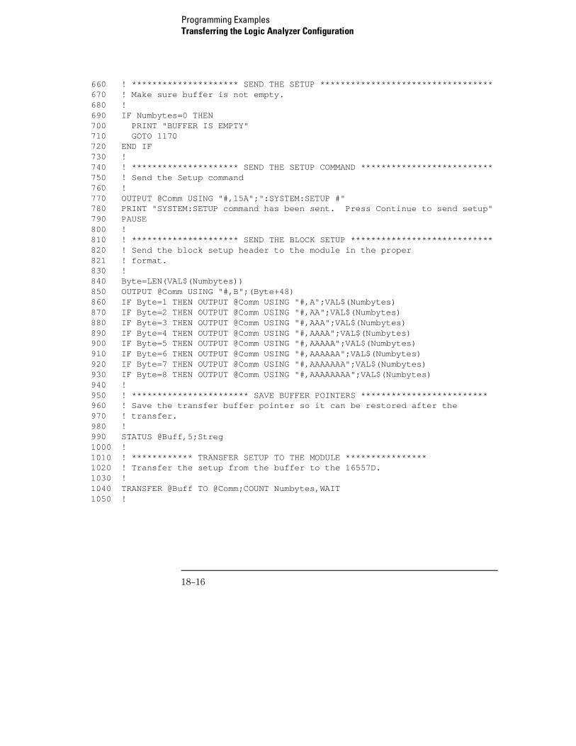
660 ! ********************* SEND THE SETUP **********************************670 ! Make sure buffer is not empty.680 !690 IF Numbytes=0 THEN 700 PRINT "BUFFER IS EMPTY"710 GOTO 1170720 END IF730 !740 ! ********************* SEND THE SETUP COMMAND **************************750 ! Send the Setup command760 !770 OUTPUT @Comm USING "#,15A";":SYSTEM:SETUP #"780 PRINT "SYSTEM:SETUP command has been sent. Press Continue to send setup"790 PAUSE800 !810 ! ********************* SEND THE BLOCK SETUP ****************************820 ! Send the block setup header to the module in the proper 821 ! format.830 !840 Byte=LEN(VAL$(Numbytes))850 OUTPUT @Comm USING "#,B";(Byte+48)860 IF Byte=1 THEN OUTPUT @Comm USING "#,A";VAL$(Numbytes)870 IF Byte=2 THEN OUTPUT @Comm USING "#,AA";VAL$(Numbytes)880 IF Byte=3 THEN OUTPUT @Comm USING "#,AAA";VAL$(Numbytes)890 IF Byte=4 THEN OUTPUT @Comm USING "#,AAAA";VAL$(Numbytes)900 IF Byte=5 THEN OUTPUT @Comm USING "#,AAAAA";VAL$(Numbytes)910 IF Byte=6 THEN OUTPUT @Comm USING "#,AAAAAA";VAL$(Numbytes)920 IF Byte=7 THEN OUTPUT @Comm USING "#,AAAAAAA";VAL$(Numbytes)930 IF Byte=8 THEN OUTPUT @Comm USING "#,AAAAAAAA";VAL$(Numbytes)940 !950 ! *********************** SAVE BUFFER POINTERS *************************960 ! Save the transfer buffer pointer so it can be restored after the970 ! transfer.980 !990 STATUS @Buff,5;Streg1000 !1010 ! ************ TRANSFER SETUP TO THE MODULE ****************1020 ! Transfer the setup from the buffer to the 16557D.1030 !1040 TRANSFER @Buff TO @Comm;COUNT Numbytes,WAIT1050 !
Programming ExamplesTransferring the Logic Analyzer Configuration
18–16
1060 ! ********************** RESTORE BUFFER POINTERS ***********************1070 ! Restore the transfer buffer pointer1080 !1090 CONTROL @Buff,5;Streg1100 !1110 ! ******************** SEND TERMINATING LINE FEED **********************1120 ! Send the terminating linefeed to properly terminate the setup string.1130 !1140 OUTPUT @Comm;""1150 !1160 PRINT "**** SENT THE SETUP **** Program complete."1170 END
Programming ExamplesTransferring the Logic Analyzer Configuration
18–17
Checking for Measurement Completion
This program can be appended to or inserted into another program when youneed to know when a measurement is complete. If it is at the end of aprogram it will tell you when measurement is complete. If you insert it into aprogram, it will halt the program until the current measurement is complete.In this example, the module installed in slot B is being checked formeasurement complete.
This program is also in the state analyzer example program in "Making a StateAnalyzer Measurement" on page 18-5. It is included in the state analyzerexample program to show how it can be used in a program to halt theprogram until measurement is complete.
420 ! ****************** CHECK FOR MEASUREMENT COMPLETE **********************430 ! Enable the MESR register and query the register for a measurement440 ! complete condition.450 !460 OUTPUT 707;":SYSTEM:HEADER OFF"470 OUTPUT 707;":SYSTEM:LONGFORM OFF"480 !490 Status=0500 OUTPUT 707;":MESE2 1" ! Enables register for slot B510 OUTPUT 707;":MESR2?" ! Queries register for slot B520 ENTER 707;Status530 !540 ! Print the MESR register status.550 !560 CLEAR SCREEN570 PRINT "Measurement complete status is ";Status AND 1580 PRINT "0 = not complete, 1 = complete"590 ! Repeat the MESR query until measurement is complete.600 WAIT 1610 IF (Status AND 1)=1 THEN GOTO 630620 GOTO 510630 PRINT TABXY(30,15);"Measurement is complete"640 !650 END
Programming ExamplesChecking for Measurement Completion
18–18
Sending Queries to the Logic Analyzer
This program example contains the steps required to send a query to thelogic analyzer. Sending the query alone only puts the requested informationin an output buffer of the logic analyzer. You must follow the query with anENTER statement to transfer the query response to the controller. When thequery response is sent to the logic analyzer, the query is properly terminatedin the logic analyzer. If you send the query but fail to send an ENTERstatement, the logic analyzer will display the error message "QueryInterrupted" when it receives the next command from the controller, and thequery response is lost.
10 ! ****************** DATA COMMAND AND QUERY EXAMPLE ********************20 ! for the 16557D30 !40 ! ********************* CREATE TRANSFER BUFFER *************************50 !53 ! NOTE WELL! The data from the 16557D may be up to 121 Mbytes long!54 ! You may estimate the size of the buffer needed for UNPACKED data using55 ! the following formula. UNPACKED DATA CANNOT BE RELOADED.56 !57 ! LET Cards = Number of 16557 cards in your module.58 ! LET Samples = Memory Length (see Acquisition Control in Trigger Menu)59 ! LET BufferSize = (12 * Samples * Cards) + 100060 !61 ! For example, a 1-card module with a full memory length of 208076862 ! requires (12 * 2080768) + 1000 = 24,970,216 bytes.63 !64 ! You may have to enlarge the workspace of your Basic environment65 ! to accomodate this buffer.66 ASSIGN @Buff TO BUFFER [3700000] !Can handle up to 300K memory depth70 !80 ! **************** INITIALIZE GPIB DEFAULT ADDRESS *********************90 !100 REAL Address110 Address=707120 ASSIGN @Comm TO Address130 !140 CLEAR SCREEN
Programming ExamplesSending Queries to the Logic Analyzer
18–19
150 !160 ! ************* INITIALIZE VARIABLE FOR NUMBER OF BYTES *****************170 ! The variable "Numbytes" contains the number of bytes in the buffer.180 !190 REAL Numbytes200 Numbytes=0210 !220 ! ************** RE-INITIALIZE TRANSFER BUFFER POINTERS ******************230 !240 CONTROL @Buff,3;1250 CONTROL @Buff,4;0260 !270 ! *********************** SEND THE DATA QUERY **************************280 OUTPUT 707;":SYSTEM:HEADER ON"290 OUTPUT 707;":SYSTEM:LONGFORM ON"300 OUTPUT @Comm;"SELECT 2"305 OUTPUT @Comm;"DBLOCK UNPACKED"310 OUTPUT @Comm;":SYSTEM:DATA?"320 !330 ! ******************** ENTER THE BLOCK DATA HEADER *********************340 ! Enter the block data header in the proper format.350 !360 ENTER @Comm USING "#,B";Byte370 PRINT CHR$(Byte);380 WHILE Byte<>35390 ENTER @Comm USING "#,B";Byte400 PRINT CHR$(Byte);410 END WHILE420 ENTER @Comm USING "#,B";Byte430 PRINT CHR$(Byte);440 Byte=Byte-48450 IF Byte=1 THEN ENTER @Comm USING "#,D";Numbytes460 IF Byte=2 THEN ENTER @Comm USING "#,DD";Numbytes470 IF Byte=3 THEN ENTER @Comm USING "#,DDD";Numbytes480 IF Byte=4 THEN ENTER @Comm USING "#,DDDD";Numbytes490 IF Byte=5 THEN ENTER @Comm USING "#,DDDDD";Numbytes500 IF Byte=6 THEN ENTER @Comm USING "#,DDDDDD";Numbytes510 IF Byte=7 THEN ENTER @Comm USING "#,DDDDDDD";Numbytes520 IF Byte=8 THEN ENTER @Comm USING "#,DDDDDDDD";Numbytes530 Str1$=DVAL$(Numbytes,10)531 ! DVAL$ returns an 11 character string532 PRINT Str1$[12-Byte]540 !
Programming ExamplesSending Queries to the Logic Analyzer
18–20
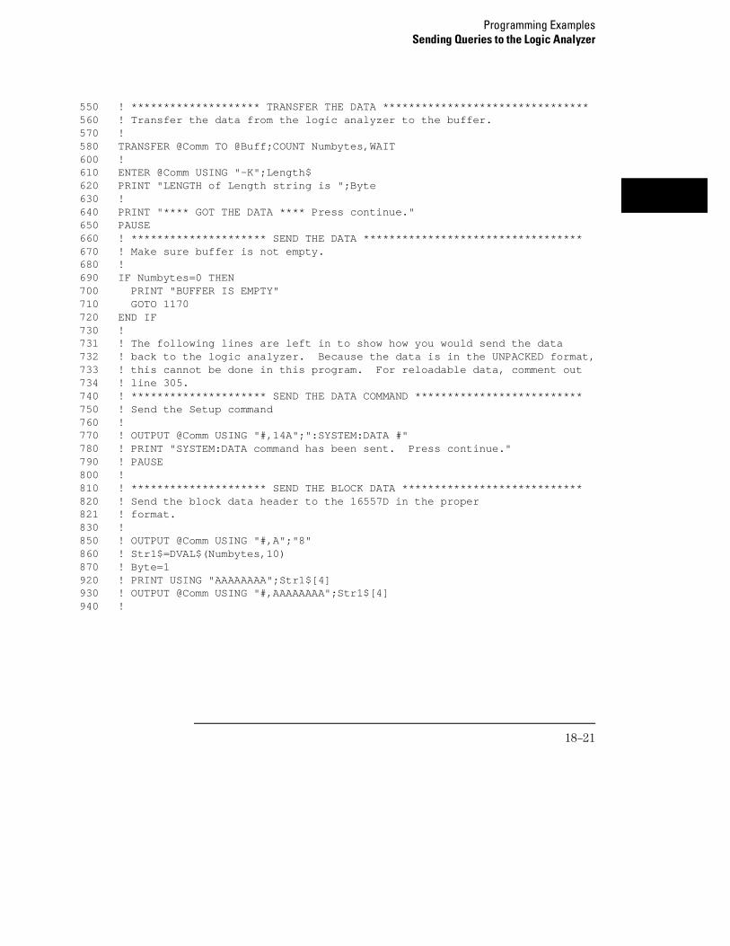
550 ! ******************** TRANSFER THE DATA ********************************560 ! Transfer the data from the logic analyzer to the buffer.570 !580 TRANSFER @Comm TO @Buff;COUNT Numbytes,WAIT600 !610 ENTER @Comm USING "-K";Length$620 PRINT "LENGTH of Length string is ";Byte630 !640 PRINT "**** GOT THE DATA **** Press continue."650 PAUSE660 ! ********************* SEND THE DATA **********************************670 ! Make sure buffer is not empty.680 !690 IF Numbytes=0 THEN700 PRINT "BUFFER IS EMPTY"710 GOTO 1170720 END IF730 ! 731 ! The following lines are left in to show how you would send the data732 ! back to the logic analyzer. Because the data is in the UNPACKED format,733 ! this cannot be done in this program. For reloadable data, comment out734 ! line 305.740 ! ********************* SEND THE DATA COMMAND **************************750 ! Send the Setup command760 !770 ! OUTPUT @Comm USING "#,14A";":SYSTEM:DATA #"780 ! PRINT "SYSTEM:DATA command has been sent. Press continue."790 ! PAUSE800 !810 ! ********************* SEND THE BLOCK DATA ****************************820 ! Send the block data header to the 16557D in the proper 821 ! format.830 !850 ! OUTPUT @Comm USING "#,A";"8"860 ! Str1$=DVAL$(Numbytes,10)870 ! Byte=1920 ! PRINT USING "AAAAAAAA";Str1$[4]930 ! OUTPUT @Comm USING "#,AAAAAAAA";Str1$[4]940 !
Programming ExamplesSending Queries to the Logic Analyzer
18–21
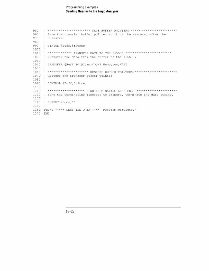
950 ! *********************** SAVE BUFFER POINTERS *************************960 ! Save the transfer buffer pointer so it can be restored after the970 ! transfer.980 !990 ! STATUS @Buff,5;Streg1000 !1010 ! ************* TRANSFER DATA TO THE 16557D *************************1020 ! Transfer the data from the buffer to the 16557D.1030 !1040 ! TRANSFER @Buff TO @Comm;COUNT Numbytes,WAIT1050 !1060 ! ********************** RESTORE BUFFER POINTERS ***********************1070 ! Restore the transfer buffer pointer1080 !1090 ! CONTROL @Buff,5;Streg1100 !1110 ! ******************** SEND TERMINATING LINE FEED **********************1120 ! Send the terminating linefeed to properly terminate the data string.1130 !1140 ! OUTPUT @Comm;""1150 !1160 PRINT "**** SENT THE DATA **** Program complete."1170 END
Programming ExamplesSending Queries to the Logic Analyzer
18–22
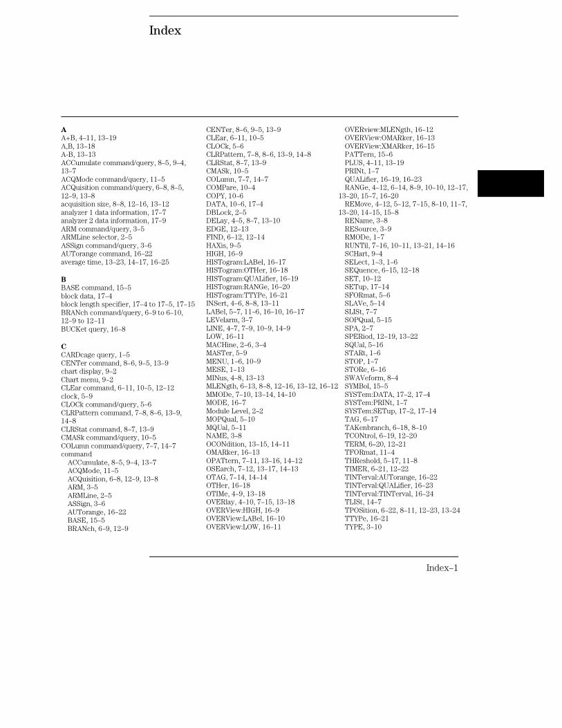
Index
A
A+B, 4–11, 13–19A,B, 13–18A-B, 13–13ACCumulate command/query, 8–5, 9–4,13–7ACQMode command/query, 11–5ACQuisition command/query, 6–8, 8–5,12–9, 13–8acquisition size, 8–8, 12–16, 13–12analyzer 1 data information, 17–7analyzer 2 data information, 17–9ARM command/query, 3–5ARMLine selector, 2–5ASSign command/query, 3–6AUTorange command, 16–22average time, 13–23, 14–17, 16–25
B
BASE command, 15–5block data, 17–4block length specifier, 17–4 to 17–5, 17–15BRANch command/query, 6–9 to 6–10,12–9 to 12–11BUCKet query, 16–8
C
CARDcage query, 1–5CENTer command, 8–6, 9–5, 13–9chart display, 9–2Chart menu, 9–2CLEar command, 6–11, 10–5, 12–12clock, 5–9CLOCk command/query, 5–6CLRPattern command, 7–8, 8–6, 13–9,14–8CLRStat command, 8–7, 13–9CMASk command/query, 10–5COLumn command/query, 7–7, 14–7command
ACCumulate, 8–5, 9–4, 13–7ACQMode, 11–5ACQuisition, 6–8, 12–9, 13–8ARM, 3–5ARMLine, 2–5ASSign, 3–6AUTorange, 16–22BASE, 15–5BRANch, 6–9, 12–9
CENTer, 8–6, 9–5, 13–9CLEar, 6–11, 10–5CLOCk, 5–6CLRPattern, 7–8, 8–6, 13–9, 14–8CLRStat, 8–7, 13–9CMASk, 10–5COLumn, 7–7, 14–7COMPare, 10–4COPY, 10–6DATA, 10–6, 17–4DBLock, 2–5DELay, 4–5, 8–7, 13–10EDGE, 12–13FIND, 6–12, 12–14HAXis, 9–5HIGH, 16–9HISTogram:LABel, 16–17HISTogram:OTHer, 16–18HISTogram:QUALifier, 16–19HISTogram:RANGe, 16–20HISTogram:TTYPe, 16–21INSert, 4–6, 8–8, 13–11LABel, 5–7, 11–6, 16–10, 16–17LEVelarm, 3–7LINE, 4–7, 7–9, 10–9, 14–9LOW, 16–11MACHine, 2–6, 3–4MASTer, 5–9MENU, 1–6, 10–9MESE, 1–13MINus, 4–8, 13–13MLENgth, 6–13, 8–8, 12–16, 13–12, 16–12MMODe, 7–10, 13–14, 14–10MODE, 16–7Module Level, 2–2MOPQual, 5–10MQUal, 5–11NAME, 3–8OCONdition, 13–15, 14–11OMARker, 16–13OPATtern, 7–11, 13–16, 14–12OSEarch, 7–12, 13–17, 14–13OTAG, 7–14, 14–14OTHer, 16–18OTIMe, 4–9, 13–18OVERlay, 4–10, 7–15, 13–18OVERView:HIGH, 16–9OVERView:LABel, 16–10OVERView:LOW, 16–11
OVERview:MLENgth, 16–12OVERView:OMARker, 16–13OVERView:XMARker, 16–15PATTern, 15–6PLUS, 4–11, 13–19PRINt, 1–7QUALifier, 16–19, 16–23RANGe, 4–12, 6–14, 8–9, 10–10, 12–17,
13–20, 15–7, 16–20REMove, 4–12, 5–12, 7–15, 8–10, 11–7,
13–20, 14–15, 15–8REName, 3–8RESource, 3–9RMODe, 1–7RUNTil, 7–16, 10–11, 13–21, 14–16SCHart, 9–4SELect, 1–3, 1–6SEQuence, 6–15, 12–18SET, 10–12SETup, 17–14SFORmat, 5–6SLAVe, 5–14SLISt, 7–7SOPQual, 5–15SPA, 2–7SPERiod, 12–19, 13–22SQUal, 5–16STARt, 1–6STOP, 1–7STORe, 6–16SWAVeform, 8–4SYMBol, 15–5SYSTem:DATA, 17–2, 17–4SYSTem:PRINt, 1–7SYSTem:SETup, 17–2, 17–14TAG, 6–17TAKenbranch, 6–18, 8–10TCONtrol, 6–19, 12–20TERM, 6–20, 12–21TFORmat, 11–4THReshold, 5–17, 11–8TIMER, 6–21, 12–22TINTerval:AUTorange, 16–22TINTerval:QUALifier, 16–23TINTerval:TINTerval, 16–24TLISt, 14–7TPOSition, 6–22, 8–11, 12–23, 13–24TTYPe, 16–21TYPE, 3–10
Index–1
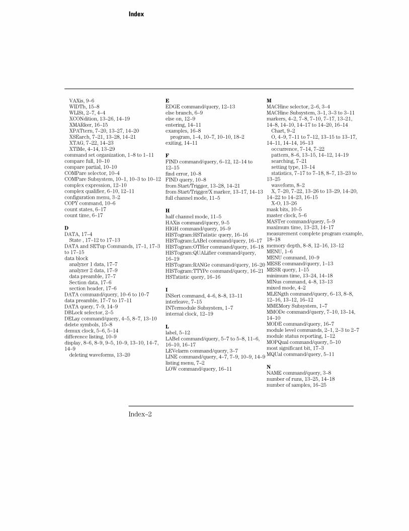
VAXis, 9–6WIDTh, 15–8WLISt, 2–7, 4–4XCONdition, 13–26, 14–19XMARker, 16–15XPATtern, 7–20, 13–27, 14–20XSEarch, 7–21, 13–28, 14–21XTAG, 7–22, 14–23XTIMe, 4–14, 13–29
command set organization, 1–8 to 1–11compare full, 10–10compare partial, 10–10COMPare selector, 10–4COMPare Subsystem, 10–1, 10–3 to 10–12complex expression, 12–10complex qualifier, 6–10, 12–11configuration menu, 3–2COPY command, 10–6count states, 6–17count time, 6–17
D
DATA, 17–4State , 17–12 to 17–13
DATA and SETup Commands, 17–1, 17–3to 17–15data block
analyzer 1 data, 17–7analyzer 2 data, 17–9data preamble, 17–7Section data, 17–6section header, 17–6
DATA command/query, 10–6 to 10–7data preamble, 17–7 to 17–11DATA query, 7–9, 14–9DBLock selector, 2–5DELay command/query, 4–5, 8–7, 13–10delete symbols, 15–8demux clock, 5–6, 5–14difference listing, 10–9display, 8–6, 8–9, 9–5, 10–9, 13–10, 14–7,14–9
deleting waveforms, 13–20
E
EDGE command/query, 12–13else branch, 6–9else on, 12–9entering, 14–11examples, 16–8
program, 1–4, 10–7, 10–10, 18–2exiting, 14–11
F
FIND command/query, 6–12, 12–14 to12–15find error, 10–8FIND query, 10–8from Start/Trigger, 13–28, 14–21from Start/Trigger/X marker, 13–17, 14–13full channel mode, 11–5
H
half channel mode, 11–5HAXis command/query, 9–5HIGH command/query, 16–9HISTogram:HSTatistic query, 16–16HISTogram:LABel command/query, 16–17HISTogram:OTHer command/query, 16–18HISTogram:QUALifier command/query,16–19HISTogram:RANGe command/query, 16–20HISTogram:TTYPe command/query, 16–21HSTatistic query, 16–16
I
INSert command, 4–6, 8–8, 13–11interleave, 7–15INTermodule Subsystem, 1–7internal clock, 12–19
L
label, 5–12LABel command/query, 5–7 to 5–8, 11–6,16–10, 16–17LEVelarm command/query, 3–7LINE command/query, 4–7, 7–9, 10–9, 14–9listing menu, 7–2LOW command/query, 16–11
M
MACHine selector, 2–6, 3–4MACHine Subsystem, 3–1, 3–3 to 3–11markers, 4–2, 7–8, 7–10, 7–17, 13–21,14–8, 14–10, 14–17 to 14–20, 16–14
Chart, 9–2O, 4–9, 7–11 to 7–12, 13–15 to 13–17,
14–11, 14–14, 16–13occurrence, 7–14, 7–22pattern, 8–6, 13–15, 14–12, 14–19searching, 7–21setting type, 13–14statistics, 7–17 to 7–18, 8–7, 13–23 to
13–25waveform, 8–2X, 7–20, 7–22, 13–26 to 13–29, 14–20,
14–22 to 14–23, 16–15X-O, 13–26
mask bits, 10–5master clock, 5–6MASTer command/query, 5–9maximum time, 13–23, 14–17measurement complete program example,18–18memory depth, 8–8, 12–16, 13–12MENU, 1–6MENU command, 10–9MESE command/query, 1–13MESR query, 1–15minimum time, 13–24, 14–18MINus command, 4–8, 13–13mixed mode, 4–2MLENgth command/query, 6–13, 8–8,12–16, 13–12, 16–12MMEMory Subsystem, 1–7MMODe command/query, 7–10, 13–14,14–10MODE command/query, 16–7module level commands, 2–1, 2–3 to 2–7module status reporting, 1–12MOPQual command/query, 5–10most significant bit, 17–3MQUal command/query, 5–11
N
NAME command/query, 3–8number of runs, 13–25, 14–18number of samples, 16–25
Index
Index–2
O
OCONdition command/query, 13–15, 14–11offset, 4–5OMARker command/query, 16–13OPATtern command/query, 7–11, 13–16,14–12OR’d trigger, 3–5OSEarch command/query, 7–12, 13–17,14–13OSTate query, 4–9, 7–13, 14–14OTAG command/query, 7–14, 14–14OTHer command/query, 16–18OTIMe command/query, 4–9, 13–18OVERlay command/query, 4–10, 7–15,13–18OVERView:BUCKet query, 16–8OVERView:HIGH command/query, 16–9OVERView:LABel command/query, 16–10OVERView:LOW command/query, 16–11OVERview:MLENgth command/query,16–12OVERView:OMARker command/query,16–13OVERView:OVSTatistic query, 16–14OVERView:XMARker command/query,16–15OVSTatistic query, 16–14
P
PATTern command, 15–6pattern markers, 7–8, 7–10 to 7–11, 8–6,13–14, 13–26 to 13–27, 14–10 to 14–12PLUS command, 4–11, 13–19pod clock, 5–7poststore, 8–11preamble description, 17–7prestore, 8–11program example
checking for measurement complete, 18–18sending queries to the logic analyzer, 18–19state analyzer, 18–5state compare, 18–9SYSTem:SETup command, 18–14SYSTem:SETup query, 18–14timing analyzer, 18–3
transferring configuration to analyzer,18–14
transferring configuration to thecontroller, 18–14
Q
QUALifier command/query, 16–19, 16–23Query
ACCumulate, 8–5, 9–4, 13–8ACQMode, 11–5ACQuisition, 6–8, 12–9, 13–8ARM, 3–5ASSign, 3–6BRANch, 6–10, 12–11BUCKet, 16–8CARDcage, 1–5CLOCk, 5–7CMASk, 10–5COLumn, 7–8, 14–8DATA, 7–9, 10–7, 14–9, 17–5DELay, 4–5, 8–7, 13–10EDGE, 12–14ERRor, 1–7FIND, 6–13, 10–8, 12–15HAXis, 9–6HIGH, 16–9HISTogram:HSTatistic, 16–16HISTogram:LABel, 16–17HISTogram:OTHer, 16–18HISTogram:QUALifier, 16–19HISTogram:RANGe, 16–20HISTogram:TTYPe, 16–21HSTatistic, 16–16LABel, 5–8, 11–7, 16–10, 16–17LEVelarm, 3–7LINE, 4–8, 7–10, 10–9, 14–10LOW, 16–11MASTer, 5–9MENU, 1–6MESE, 1–13MESR, 1–15MLENgth, 6–13, 8–9, 12–16, 13–13, 16–12MMODe, 7–11, 13–14, 14–10MODE, 16–7MOPQual, 5–10MQUal, 5–11NAME, 3–8OCONdition, 13–15, 14–11
OMARker, 16–13OPATtern, 7–12, 13–16, 14–12OSEarch, 7–13, 13–17, 14–13OSTate, 4–9, 7–13, 14–14OTAG, 7–14, 14–15OTHer, 16–18OTIMe, 4–10, 13–18OVERView:BUCKet, 16–8OVERView:HIGH, 16–9OVERView:LABel, 16–10OVERView:LOW, 16–11OVERview:MLENgth, 16–12OVERView:OMARker, 16–13OVERView:OVSTatistic, 16–14OVERView:XMARker, 16–15OVSTatistic, 16–14PRINt, 1–7QUALifier, 16–19, 16–23RANGe, 4–12, 6–15, 8–9, 10–10, 12–17,
13–20, 16–20REName, 3–9RESource, 3–10RMODe, 1–7RUNTil, 7–16, 10–12, 13–21, 14–16SEQuence, 6–15, 12–18SETup, 17–15SLAVe, 5–14SOPQual, 5–15SPERiod, 12–19, 13–22SQUal, 5–16STORe, 6–16SYSTem:DATA, 17–5SYSTem:ERRor, 1–7SYSTem:PRINt, 1–7SYStem:SETup, 17–15TAG, 6–17TAKenbranch, 6–18, 8–10TAVerage, 7–17, 13–23, 14–17TCONtrol, 6–19, 12–20TERM, 6–21, 12–22THReshold, 5–17, 11–8TIMER, 6–21, 12–22TINTerval:QUALifier, 16–23TINTerval:TINTerval, 16–24TINTerval:TSTatistic, 16–25TMAXimum, 7–17, 13–23, 14–17TMINimum, 7–18, 13–24, 14–18TPOSition, 6–22, 8–11, 12–23, 13–25
Index
Index–3
TSTatistic, 16–25TTYPe, 16–21TYPE, 3–11VAXis, 9–7VRUNs, 7–18, 13–25, 14–18XCONdition, 13–26, 14–19XMARker, 16–15XOTag, 7–19, 14–19XOTime, 4–13, 7–19, 13–26, 14–20XPATtern, 7–20, 13–27, 14–21XSEarch, 7–21, 13–28, 14–22XSTate, 4–13, 7–22, 14–22XTAG, 7–23, 14–23XTIMe, 4–14, 13–29
query program example, 18–19
R
RANGe command/query, 4–12, 6–14, 8–9,10–10, 12–17, 13–20, 15–7, 16–20reference listing, 10–6, 10–9REMove command, 4–12, 5–12, 7–15,8–10, 11–7, 13–20, 14–15, 15–8REName command/query, 3–8RESource command/query, 3–9RMODe, 1–7RUNTil command/query, 7–16, 10–11,13–21, 14–16
S
s/Div, 4–12sample period, 13–22sample rate, 12–19SCHart selector, 9–4SCHart Subsystem, 9–1, 9–3 to 9–7scroll listing, 14–9search, 7–12, 7–21searching, 14–13sec/Div, 13–20section data, 17–6section data format, 17–4section header, 17–6SELect command, 1–3, 1–6SEQuence command/query, 6–15, 12–18SET command, 10–12SETup, 17–14SFORmat selector, 5–6SFORmat Subsystem, 5–1, 5–3 to 5–17slave clock, 5–6
SLAVe command/query, 5–14SLISt selector, 7–7SLISt Subsystem, 7–1, 7–3 to 7–23SOPQual command/query, 5–15SPA selector, 2–7specify patterns, 13–9, 14–8, 14–12, 14–19SPERiod command/query, 12–19, 13–22SQUal command/query, 5–16STARt, 1–6state analyzer
program example, 18–5state markers, 7–10states/Div, 8–9statistics, 7–10, 13–23 to 13–25, 16–14,16–16, 16–22, 16–25statistics markers, 7–18, 8–7, 13–14,14–10, 14–17 to 14–18STOP, 1–7stop measurement, 7–16, 10–11, 13–21,14–16STORe command/query, 6–16STRace selector, 6–8STRigger selector, 6–8STRigger/STRace Subsystem, 6–1, 6–3 to6–22Subsystem
COMPare, 10–2MACHine, 3–2SCHart, 9–2SFORmat, 5–1, 5–3 to 5–17SLISt, 7–1, 7–3 to 7–23STRigger/STRace, 6–1, 6–3 to 6–22SWAVeform, 8–2SYMBol, 15–1, 15–3 to 15–8TFORmat, 11–1, 11–3 to 11–8TLISt, 14–1, 14–3 to 14–23TTRigger/TTRace, 12–1, 12–3 to 12–23TWAVeform, 13–1, 13–3 to 13–29WLISt, 4–1, 4–3 to 4–14
SWAVeform selector, 8–4SWAVeform Subsystem, 8–1, 8–3 to 8–11SYMBol selector, 15–5SYMBol Subsystem, 15–1, 15–3 to 15–8syntax diagram
COMPare Subsystem, 10–3MACHine Subsystem, 3–3SCHart Subsystem, 9–3SFORmat Subsystem, 5–3
SLISt Subsystem, 7–3STRigger Subsystem, 6–3 to 6–4SWAVeform Subsystem, 8–3SYMBol Subsystem, 15–3TFORmat Subsystem, 11–3TLISt Subsystem, 14–3TTRigger Subsystem, 12–3TWAVeform Subsystem, 13–3 to 13–4WLISt Subsystem, 4–3
SYSTem:DATA, 17–4 to 17–5SYSTem:ERRor, 1–7SYSTem:PRINt, 1–7SYStem:SETup, 17–14 to 17–15SYSTem:SETup program example, 18–14
T
TAG command/query, 6–17TAKenbranch command/query, 6–18, 8–10TAVerage query, 7–17, 13–23, 14–17TCONtrol command/query, 6–19, 12–20TERM command/query, 6–20, 12–21TFORmat selector, 11–4TFORmat Subsystem, 11–1, 11–3 to 11–8THReshold command/query, 5–17, 11–8time markers, 7–10, 13–14, 13–18, 13–26,13–29, 14–10time tag data description, 17–14time tags, 14–7timer, 6–19, 6–21, 12–20TIMER command/query, 6–21, 12–22timing analyzer
program example, 18–3TINTerval:AUTorange command, 16–22TINTerval:QUALifier command/query,16–23TINTerval:TINTerval command/query,16–24TINTerval:TSTatistic query, 16–25TLISt selector, 14–7TLISt Subsystem, 14–1, 14–3 to 14–23TMAXimum query, 7–17, 13–23, 14–17TMINimum query, 7–18, 13–24, 14–18TPOSition command/query, 6–22, 8–11,12–23, 13–24trace size, 8–8, 12–16trigger, 8–11, 12–14
SPA, 16–21trigger position, 13–24
Index
Index–4
TSTatistic query, 16–25TTRace selector, 12–8TTRigger selector, 12–8TTRigger/TTRace Subsystem, 12–1, 12–3to 12–23TTYPe command/query, 16–21TWAVeform selector, 13–7TWAVeform Subsystem, 13–1, 13–3 to13–29TYPE command/query, 3–10 to 3–11
V
VAXis command/query, 9–6 to 9–7vertical scroll, 4–7VRUNs query, 7–18, 13–25, 14–18
W
WIDTh command, 15–8WLISt selector, 2–7, 4–4WLISt Subsystem, 4–1, 4–3 to 4–14
X
X entering, 14–19X exiting, 14–19XCONdition command/query, 13–26, 14–19XMARker command/query, 16–15XOTag query, 7–19, 14–19XOTime query, 4–13, 7–19, 13–26, 14–20XPATtern command/query, 7–20, 13–27,14–20XSEarch command/query, 7–21, 13–28,14–21XSTate query, 4–13, 7–22, 14–22XTAG command/query, 7–22 to 7–23,14–23XTIMe command/query, 4–14, 13–29
Index
Index–5

Index
Index–6
© Copyright AgilentTechnologies 1998-2000All Rights Reserved.
Reproduction, adaptation, ortranslation without priorwritten permission isprohibited, except as allowedunder the copyright laws.
Restricted Rights Legend.
Use, duplication or disclosureby the U.S. Government issubject to restrictions as setforth in subparagraph (c) (1)(ii) of the Rights in TechnicalData and Computer Softwareclause at DFARS252.227-7013 for DODagencies, and subparagraphs(c) (1) and (c) (2) of theCommercial ComputerSoftware Restricted Rightsclause at FAR 52.227-19 forother agencies.Agilent Technologies3000 Hanover StreetPalo Alto, California 94304U.S.A.
Document Warranty
The information contained inthis document is subject tochange without notice.Agilent Technologies
makes no warranty of any
kind with regard to this
material, including, but
not limited to, the implied
warranties of
merchantability or fitness
for a particular purpose.
Agilent Technologies shall notbe liable for errors containedherein or for damages inconnection with thefurnishing, performance, oruse of this material.
Safety
This apparatus has beendesigned and tested inaccordance with IECPublication 1010, SafetyRequirements for MeasuringApparatus, and has beensupplied in a safe condition.This is a Safety Class Iinstrument (provided withterminal for protectiveearthing). Before applyingpower, verify that the correctsafety precautions are taken(see the following warnings).In addition, note the externalmarkings on the instrumentthat are described under"Safety Symbols."
Warning
• Before turning on theinstrument, you must connectthe protective earth terminalof the instrument to theprotective conductor of the(mains) power cord. Themains plug shall only beinserted in a socket outletprovided with a protectiveearth contact. You must notnegate the protective actionby using an extension cord(power cable) without aprotective conductor(grounding). Grounding oneconductor of a two-conductoroutlet is not sufficientprotection.
• Only fuses with therequired rated current,voltage, and specified type(normal blow, time delay,etc.) should be used. Do notuse repaired fuses orshort-circuited fuseholders.To do so could cause a shockor fire hazard.
• Service instructions are fortrained service personnel. Toavoid dangerous electricshock, do not perform anyservice unless qualified to doso. Do not attempt internalservice or adjustment unlessanother person, capable ofrendering first aid andresuscitation, is present.
• If you energize thisinstrument by an autotransformer (for voltagereduction), make sure thecommon terminal isconnected to the earthterminal of the power source.
• Whenever it is likely thatthe ground protection isimpaired, you must make theinstrument inoperative andsecure it against anyunintended operation.
• Do not operate theinstrument in the presence offlammable gasses or fumes.Operation of any electricalinstrument in such anenvironment constitutes adefinite safety hazard.
• Do not install substituteparts or perform anyunauthorized modification tothe instrument.
• Capacitors inside theinstrument may retain acharge even if the instrumentis disconnected from itssource of supply.
• Use caution when exposingor handling the CRT.Handling or replacing theCRT shall be done only byqualified maintenancepersonnel.
Safety Symbols
Instruction manual symbol:the product is marked withthis symbol when it isnecessary for you to refer tothe instruction manual inorder to protect againstdamage to the product.
Hazardous voltage symbol.
Earth terminal symbol: Usedto indicate a circuit commonconnected to groundedchassis.
W A R N I N G
The Warning sign denotes ahazard. It calls attention to aprocedure, practice, or thelike, which, if not correctlyperformed or adhered to,could result in personalinjury. Do not proceedbeyond a Warning sign untilthe indicated conditions arefully understood and met.
C A U T I O N
The Caution sign denotes ahazard. It calls attention toan operating procedure,practice, or the like, which, ifnot correctly performed oradhered to, could result indamage to or destruction ofpart or all of the product. Donot proceed beyond aCaution symbol until theindicated conditions are fullyunderstood or met.
Agilent TechnologiesP.O. Box 21971900 Garden of the Gods RoadColorado Springs, CO 80901
Product Warranty
This Agilent Technologiesproduct has a warrantyagainst defects in materialand workmanship for a periodof one year from date ofshipment. During thewarranty period, AgilentTechnologies will, at itsoption, either repair orreplace products that proveto be defective.For warranty service orrepair, this product must bereturned to a service facilitydesignated by AgilentTechnologies.For products returned toAgilent Technologies forwarranty service, the Buyershall prepay shipping chargesto Agilent Technologies andAgilent Technologies shallpay shipping charges toreturn the product to theBuyer. However, the Buyershall pay all shipping charges,duties, and taxes for productsreturned to AgilentTechnologies from anothercountry.Agilent Technologieswarrants that its software andfirmware designated byAgilent Technologies for usewith an instrument willexecute its programminginstructions when properlyinstalled on that instrument.Agilent Technologies doesnot warrant that theoperation of the instrumentsoftware, or firmware will beuninterrupted or error free.
Limitation of Warranty
The foregoing warranty shallnot apply to defects resultingfrom improper or inadequatemaintenance by the Buyer,Buyer-supplied software orinterfacing, unauthorizedmodification or misuse,operation outside of theenvironmental specificationsfor the product, or impropersite preparation ormaintenance.
No other warranty is
expressed or implied.
Agilent Technologies
specifically disclaims the
implied warranties of
merchantability or fitness
for a particular purpose.
Exclusive Remedies
The remedies providedherein are the buyer’s soleand exclusive remedies.Agilent Technologies shallnot be liable for any direct,indirect, special, incidental,or consequential damages,whether based on contract,tort, or any other legal theory.
Assistance
Product maintenanceagreements and othercustomer assistanceagreements are available forAgilent Technologiesproducts.For any assistance, contactyour nearest AgilentTechnologies Sales Office.
Certification
Agilent Technologies certifiesthat this product met itspublished specifications atthe time of shipment from thefactory. Agilent Technologiesfurther certifies that itscalibration measurements aretraceable to the United StatesNational Institute ofStandards and Technology, tothe extent allowed by theInstitute’s calibration facility,and to the calibrationfacilities of otherInternational StandardsOrganization members.
About this edition
This is the Agilent
Technologies 16557D
State/Timing Logic
Analyzer Programmer’s
Guide.
Publication number16557-97005, January 2000Printed in USA.
Print history is as follows:16557-97001, April 199816557-97005, January 2000
New editions are completerevisions of the manual. Manyproduct updates do notrequire manual changes; and,conversely, manualcorrections may be donewithout accompanyingproduct changes. Therefore,do not expect a one-to-onecorrespondence betweenproduct updates and manualupdates.