Embed Size (px)
Citation preview

Agilent U8903B Audio Analyzer
User’s Guide
Agilent Technologies

II U8903B User’s Guide
Notices© Agilent Technologies, Inc. 2014
No part of this manual may be reproduced in any form or by any means (including elec-tronic storage and retrieval or translation into a foreign language) without prior agree-ment and written consent from Agilent Technologies, Inc. as governed by United States and international copyright laws.
Manual Part NumberU8903-90045
EditionFirst Edition, June 4, 2014
Agilent Technologies, Inc. 5301, Stevens Creek Blvd. Santa Clara, CA 95051 USA
WarrantyThe material contained in this document is provided “as is,” and is subject to change, without notice, in future editions. Further, to the maximum extent permitted by the applicable law, Agilent disclaims all war-ranties, either express or implied, with regard to this manual and any information contained herein, including but not limited to the implied warranties of merchantabil-ity and fitness for a particular purpose. Agilent shall not be liable for errors or for incidental or consequential damages in connection with the furnishing, use, or performance of this document or of any information contained herein. Should Agi-lent and the user have a separate written agreement with warranty terms covering the material in this document that conflict with these terms, the warranty terms in the separate agreement shall control.
Technology Licenses The hardware and or software described in this document are furnished under a license and may be used or copied only in accor-dance with the terms of such license.
Restricted Rights LegendU.S. Government Restricted Rights. Soft-ware and technical data rights granted to the federal government include only those rights customarily provided to end user cus-tomers. Agilent provides this customary commercial license in Software and techni-cal data pursuant to FAR 12.211 (Technical Data) and 12.212 (Computer Software) and, for the Department of Defense, DFARS 252.227-7015 (Technical Data - Commercial Items) and DFARS 227.7202-3 (Rights in Commercial Computer Software or Com-puter Software Documentation).
Safety Notices
CAUTION
A CAUTION notice denotes a haz-ard. It calls attention to an operat-ing procedure, practice, or the likes of that, if not correctly performed or adhered to, could result in dam-age to the product or loss of impor-tant data. Do not proceed beyond a CAUTION notice until the indicated conditions are fully understood and met.
WARNING
A WARNING notice denotes a hazard. It calls attention to an operating procedure, practice, or the likes of that, if not correctly performed or adhered to, could result in personal injury or death. Do not proceed beyond a WARN-ING notice until the indicated conditions are fully understood and met.

Safety Symbols
The following symbols on the instrument and in the documentation indicate precautions which must be taken to maintain safe operation of the instrument.
Direct current (DC) Off (supply)
Alternating current (AC) On (supply)
Caution, risk of electric shockCaution, risk of danger (refer to this manual for specific Warning or Caution information)
Earth (ground) terminalEquipment protected throughout by doubleinsulation or reinforced insulation
Frame or chassis terminal Protective conductor terminal
U8903B User’s Guide III

Safety Considerations
Read the information below before using this instrument.
The following general safety precautions must be observed during all phases of operation, service, and repair of this instrument. Failure to comply with these precautions or with specific warnings elsewhere in this manual violates safety standards for design, manufacture, and intended use of the instrument. Agilent Technologies assumes no liability for the customer’s failure to comply with these requirements.
WARNING • Do not use the device if it is damaged. Before you use the device, inspect the casing. Look for cracks or missing plastic. Do not operate the device around explosive gas, vapor, or dust.
• Always use the device with the cables provided.
• Observe all markings on the device before establishing any connection.
• Turn off the device and application system power before connecting to the I/O terminals.
• When servicing the device, use only the specified replacement parts.
• Do not operate the device with the cover removed or loosened.
• Use only the power adapter provided by the manufacturer to avoid any unexpected hazards.
• This equipment is under measurement category as below: DO NOT CONNECT THE CABLE TO MAINS
Maximum working voltage: 200 Vp for altitude up to 3000 m Maximum transient voltage: 1210 V
• Do not measure more than the rated voltage (as marked on the device).
CAUTION • If the device is used in a manner not specified by the manufacturer, the device protection may be impaired.
• Always use dry cloth to clean the device. Do not use ethyl alcohol or any other volatile liquid to clean the device.
• Do not permit any blockage of the ventilation holes of the device.
IV U8903B User’s Guide
Environmental Conditions
This instrument is designed for indoor use and in an area with low condensation. The table below shows the general environmental requirements for this instrument.
Regulatory Information
The U8903B complies with the following safety and Electromagnetic Compatibility (EMC) compliances:
Safety compliance
• IEC 61010-1:2010/EN 61010-1:2010
• Canada: CAN/CSA-C22.2 No. 61010-1-12
• USA: ANSI/UL Std. No. 61010-1 (3rd Edition)
EMC compliance
• IEC 61326-1:2005/EN61326-1:2006
• Canada: ICES-001:2004
• Australia/New Zealand: AS/NZS CISPR11:2004
Environmental condition Requirement
Temperature
Operating condition• 0 °C to 55 °C Storage condition• –40 °C to 70 °C
Humidity
Operating condition• 20% to 80% RH (non-condensing)Storage condition• Up to 95% RH at 40 °C (non-condensing)
Altitude Up to 3000 m
Pollution degree 2
Installation category II
Measurement category I (refer to “Measurement Category" on page 333)
U8903B User’s Guide V
Regulatory Markings
The CE mark is a registered trademarkof the European Community. This CEmark shows that the product complieswith all the relevant European LegalDirectives.
The C-tick mark is a registered trademark of the Spectrum Management Agency of Australia. This signifies compliance withthe Australia EMC Frameworkregulations under the terms of the Radio Communication Act of 1992.
ICES/NMB-001 indicates that this ISM device complies with the Canadian ICES-001.Cet appareil ISM est conforme a la norme NMB-001 du Canada.
This instrument complies with the WEEE Directive (2002/96/EC) marking requirement. This affixed product label indicates that you must not discard this electrical or electronic product in domestic household waste.
The CSA mark is a registered trademark of the Canadian Standards Association.
This symbol indicates the time period during which no hazardous or toxic substance elements are expected to leak or deteriorate during normal use. Forty years is the expected useful life of the product.
VI U8903B User’s Guide
Waste Electrical and Electronic Equipment (WEEE) Directive 2002/96/EC
This instrument complies with the WEEE Directive (2002/96/EC) marking requirement. This affixed product label indicates that you must not discard this electrical or electronic product in domestic household waste.
Product Category:
With reference to the equipment types in the WEEE directive Annex 1, this instrument is classified as a “Monitoring and Control Instrument” product.
The affixed product label is as shown below.
Do not dispose in domestic household waste.
To return this unwanted instrument, contact your nearest Agilent Service Center, or visit
www.agilent.com/environment/product
for more information.
U8903B User’s Guide VII

Declaration of Conformity (DoC)
The Declaration of Conformity (DoC) for this instrument is available on the Agilent Web site. You can search the DoC by its product model or description at the Web address below.
http://regulations.corporate.agilent.com/DoC/search.htm
NOTE If you are unable to search for the respective DoC, contact your local Agilent representative.
VIII U8903B User’s Guide

Table of Contents
1 Getting Started
Introduction 2
LXI Standard 1.4 Compliant Audio Analyzer 2
Installation and Configuration 3
Initial inspection 3Ventilation 3Rack mounting 3
Standard Shipped Items 4
Optional Accessories 4
U8903B Options 5
Product at a Glance 6
Front panel 6Rear panel 8LCD display 10
Getting Started 12
Power on the U8903B 12Preset the U8903B 12Access the help mode 13Update the U8903B 14Perform self-test 16Add or remove U8903B options 17
2 Operation and Features
Test Capabilities 20
U8903B Block Diagram 21
Analog audio interface 21
Navigation and DATA ENTRY panels 23
U8903B User’s Guide IX
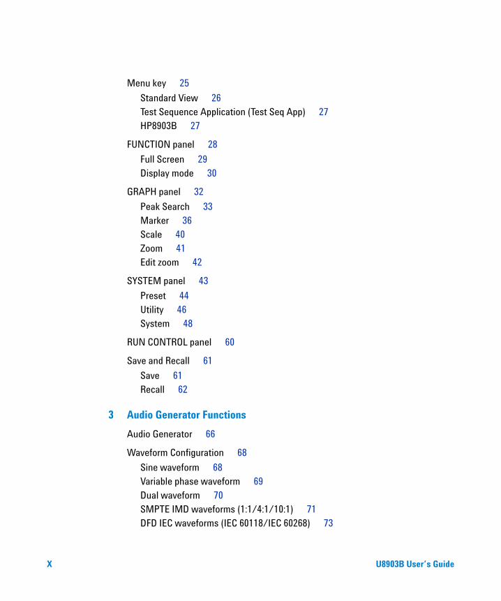
Menu key 25
Standard View 26Test Sequence Application (Test Seq App) 27HP8903B 27
FUNCTION panel 28
Full Screen 29Display mode 30
GRAPH panel 32
Peak Search 33Marker 36Scale 40Zoom 41Edit zoom 42
SYSTEM panel 43
Preset 44Utility 46System 48
RUN CONTROL panel 60
Save and Recall 61
Save 61Recall 62
3 Audio Generator Functions
Audio Generator 66
Waveform Configuration 68
Sine waveform 68Variable phase waveform 69Dual waveform 70SMPTE IMD waveforms (1:1/4:1/10:1) 71DFD IEC waveforms (IEC 60118/IEC 60268) 73
X U8903B User’s Guide

Gaussian noise 75Rectangular noise 76Pink noise 77Square waveform 78DC signal 79Arbitrary waveform 80Multitone waveform 82Dual-Tone Multi-Frequency (DTMF) 86
Output Configuration 90
References 92
4 Audio Analyzer Measurement Functions
Audio Analyzer 94
Functions 96
Measurement Functions 97
Frequency measurement 97AC voltage level measurement 99DC voltage level measurement 102THD+N ratio and THD+N level measurements 104SINAD measurement 109THD ratio and THD level measurements 111SMPTE IMD measurements 117DFD measurements 119SNR measurement 121SNR (fast mode) measurement 123
Phase measurement 125
Crosstalk measurement 127
Filters Configuration 129
Notch Filter 132
Measurement Configuration 133
U8903B User’s Guide XI

Input Configuration 135
Wave File 137
Statistics 139
5 Graph Analysis
Graph Analysis 142
Graph Settings 144
Axis Settings 147
Trace Settings 149
Memory 151Math 152Persistence 153
Display Options 154
Graph 154Data table 155Marker table 156Statistics 157Harmonics 158Signal analysis 161
Measurement Settings 162
Measurement 1/Measurement 2 163
6 Sweep Function
Sweep Parameter 166
Points settings 168Sweep channels 170
Plot View 171
Axis settings 172Plot settings 173
XII U8903B User’s Guide

Edit Points 175
7 Test Sequence Application
Test Sequence Application 179
Project 181
Properties 182
Test Sequence 183
IO Configuration 184
Settings 185Properties 190
Sub-steps 191
Prompt sub-step settings 193Send SCPI sub-step settings 195
Measurements 197
Properties 199AC level 201Frequency 206Phase 210SNR 214THD+N 221DC level 226Crosstalk 230SMPTE IMD 234DFD IMD 239Multitone analyzer 243Stepped frequency sweep 247SMPTE frequency sweep 252DFD frequency sweep 256Stepped level sweep 261SMPTE level sweep 267DFD level sweep 271
U8903B User’s Guide XIII
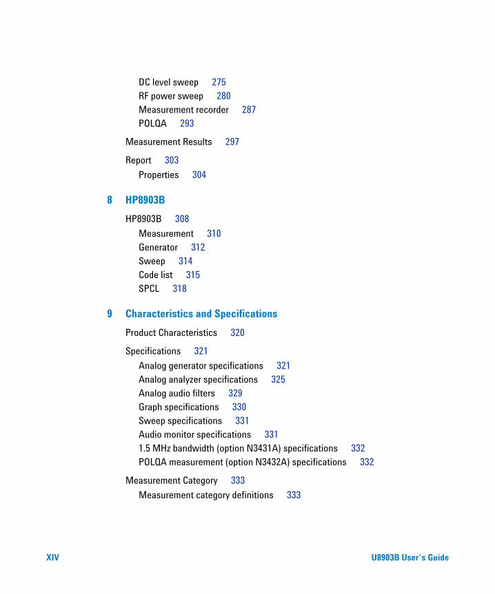
DC level sweep 275RF power sweep 280Measurement recorder 287POLQA 293
Measurement Results 297
Report 303
Properties 304
8 HP8903B
HP8903B 308
Measurement 310Generator 312Sweep 314Code list 315SPCL 318
9 Characteristics and Specifications
Product Characteristics 320
Specifications 321
Analog generator specifications 321Analog analyzer specifications 325Analog audio filters 329Graph specifications 330Sweep specifications 331Audio monitor specifications 3311.5 MHz bandwidth (option N3431A) specifications 332POLQA measurement (option N3432A) specifications 332
Measurement Category 333
Measurement category definitions 333
XIV U8903B User’s Guide

A Appendixes
Appendix A: FUNCTION panel 336
Appendix B: Graph Panel Menu Tree 337
Appendix C: System Panel Menu Tree 339
Appendix D: Analog Generator Menu Tree 344
Appendix E: Analog Analyzer Menu Tree 349
Appendix F: Graph Analysis Menu Tree 362
Appendix G: Sweep Function Menu Tree 367
Appendix H: Save Menu Tree 370
Appendix I: Recall Menu Tree 371
Appendix J: Test Sequence Menu Tree 372
Measurement settings 383Measurement results 426
Appendix K: HP8903B Menu Tree 430
Appendix L: Units of the Measurement Function Returned Values 432
Analog analyzer 432
Appendix M: Arbitrary File Format 435
Appendix N: User-defined Filter File Format 438
Appendix O: U8903B Default Settings 441
Analog generator 441Analog analyzer 442Sweep 446HP8903B 447System 448
U8903B User’s Guide XV

THIS PAGE HAS BEEN INTENTIONALLY LEFT BLANK.
XVI U8903B User’s Guide

List of Figures
Figure 1-1 U8903B front panel 6Figure 1-2 U8903B rear panel 8Figure 1-3 U8903B LCD display 10Figure 1-4 Help mode 13Figure 1-5 System > Update menu page 14Figure 1-6 Recall menu page 15Figure 1-7 System > Service > Self-Test menu page 16Figure 1-8 System > Service > Options menu page 17Figure 1-9 Recall menu page 18Figure 2-1 U8903B analog generator block diagram 21Figure 2-2 U8903B analog analyzer block diagram 22Figure 2-3 Navigation and DATA ENTRY panels 23Figure 2-4 U8903B mode selection 25Figure 2-5 Full screen graph display 29Figure 2-6 4-panel view 30Figure 2-7 10-panel view 30Figure 2-8 Graph analysis mode 2-panel view 31Figure 2-9 Peak Search menu page 33Figure 2-10 Peak Search > Threshold menu page 35Figure 2-11 Marker menu page 1 36Figure 2-12 Marker > Marker - menu page 38Figure 2-13 Marker > Harmonics menu page 39Figure 2-14 Scale menu page 40Figure 2-15 Magnified graph display 41Figure 2-16 Magnified graph display 42Figure 2-17 Preset menu page 44Figure 2-18 Utility menu page (generator and analyzer mode) 46Figure 2-19 Utility menu page (graph analysis mode) 47Figure 2-20 System menu page 1 48Figure 2-21 System > Error Info menu page (Error) 49Figure 2-22 System > I/O menu page 50Figure 2-23 System > I/O > Lan Settings menu page 1 51Figure 2-24 System > Service menu page 52Figure 2-25 System > Settings menu page 1 53Figure 2-26 System > HP8903B Config menu page 55
U8903B User’s Guide XVII

Figure 2-27 System > Fan & Temperature menu page 57Figure 2-28 System > Aux Output menu page 58Figure 2-29 System > Board Info menu page 59Figure 2-30 RUN CONTROL panel 60Figure 2-31 Save menu page 61Figure 2-32 Recall menu page 62Figure 3-1 Analog Generator menu page 66Figure 3-2 Analog Generator > Waveform Config menu page (sine waveform) 68Figure 3-3 Analog Generator > Waveform Config menu page (variable phase
waveform) 69Figure 3-4 Analog Generator > Waveform Config menu page (dual waveform) 70Figure 3-5 Analog Generator > Waveform Config menu page (SMPTE 1:1
waveform) 71Figure 3-6 Analog Generator > Waveform Config menu page (IEC 60118
waveform) 73Figure 3-7 Analog Generator > Waveform Config menu page (IEC 60268
waveform) 74Figure 3-8 Analog Generator > Waveform Config menu page (Gaussian noise) 75Figure 3-9 Analog Generator > Waveform Config menu page (Rectangular noise)
76Figure 3-10 Analog Generator > Waveform Config menu page (Pink noise) 77Figure 3-11 Analog Generator > Waveform Config menu page (square waveform)
78Figure 3-12 Analog Generator > Waveform Config menu page (DC signal) 79Figure 3-13 Analog Generator > Waveform Config menu page (arbitrary waveform)
80Figure 3-14 Analog Generator > Waveform Config menu page 1 (multitone
waveform) 82Figure 3-15 Analog Generator > Waveform Config > Custom menu page 1
(multitone waveform) 84Figure 3-16 Analog Generator > Waveform Config menu page 1 (DTMF) 86Figure 3-17 Dial menu page 88Figure 3-18 Analog Generator > Output Config menu page 90Figure 3-19 Analog Generator > References menu page 92Figure 4-1 Analog Analyzer menu page 94Figure 4-2 Analog Analyzer > Functions menu page 96Figure 4-3 Analog Analyzer > Functions > Frequency menu page 1 97Figure 4-4 Analog Analyzer > Functions > AC Voltage menu page 1 99
XVIII U8903B User’s Guide
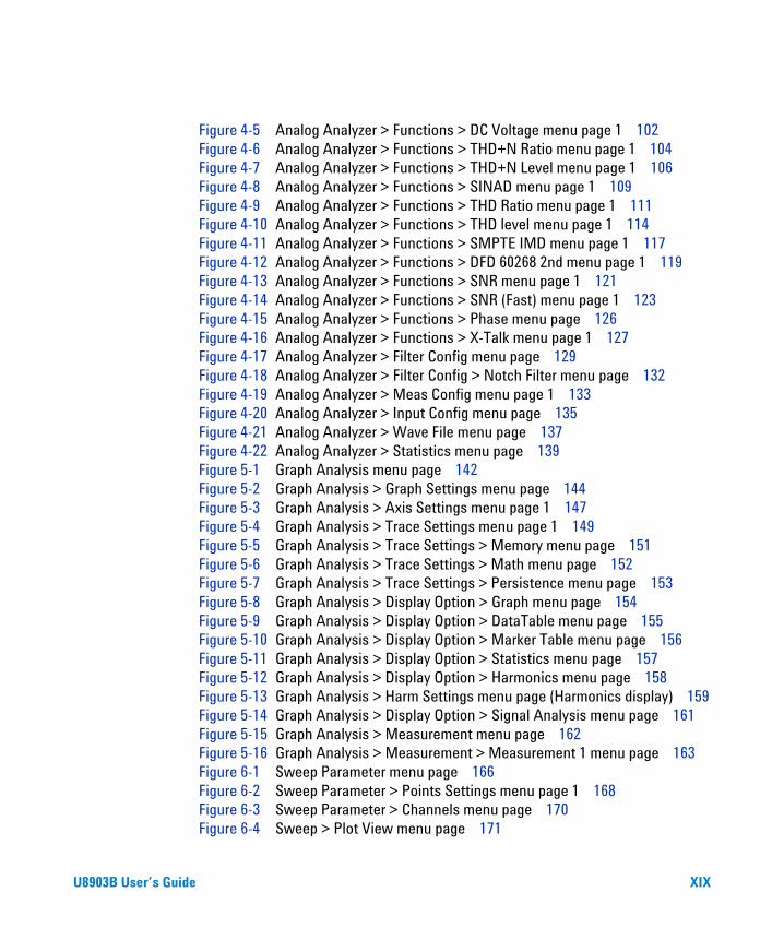
Figure 4-5 Analog Analyzer > Functions > DC Voltage menu page 1 102Figure 4-6 Analog Analyzer > Functions > THD+N Ratio menu page 1 104Figure 4-7 Analog Analyzer > Functions > THD+N Level menu page 1 106Figure 4-8 Analog Analyzer > Functions > SINAD menu page 1 109Figure 4-9 Analog Analyzer > Functions > THD Ratio menu page 1 111Figure 4-10 Analog Analyzer > Functions > THD level menu page 1 114Figure 4-11 Analog Analyzer > Functions > SMPTE IMD menu page 1 117Figure 4-12 Analog Analyzer > Functions > DFD 60268 2nd menu page 1 119Figure 4-13 Analog Analyzer > Functions > SNR menu page 1 121Figure 4-14 Analog Analyzer > Functions > SNR (Fast) menu page 1 123Figure 4-15 Analog Analyzer > Functions > Phase menu page 126Figure 4-16 Analog Analyzer > Functions > X-Talk menu page 1 127Figure 4-17 Analog Analyzer > Filter Config menu page 129Figure 4-18 Analog Analyzer > Filter Config > Notch Filter menu page 132Figure 4-19 Analog Analyzer > Meas Config menu page 1 133Figure 4-20 Analog Analyzer > Input Config menu page 135Figure 4-21 Analog Analyzer > Wave File menu page 137Figure 4-22 Analog Analyzer > Statistics menu page 139Figure 5-1 Graph Analysis menu page 142Figure 5-2 Graph Analysis > Graph Settings menu page 144Figure 5-3 Graph Analysis > Axis Settings menu page 1 147Figure 5-4 Graph Analysis > Trace Settings menu page 1 149Figure 5-5 Graph Analysis > Trace Settings > Memory menu page 151Figure 5-6 Graph Analysis > Trace Settings > Math menu page 152Figure 5-7 Graph Analysis > Trace Settings > Persistence menu page 153Figure 5-8 Graph Analysis > Display Option > Graph menu page 154Figure 5-9 Graph Analysis > Display Option > DataTable menu page 155Figure 5-10 Graph Analysis > Display Option > Marker Table menu page 156Figure 5-11 Graph Analysis > Display Option > Statistics menu page 157Figure 5-12 Graph Analysis > Display Option > Harmonics menu page 158Figure 5-13 Graph Analysis > Harm Settings menu page (Harmonics display) 159Figure 5-14 Graph Analysis > Display Option > Signal Analysis menu page 161Figure 5-15 Graph Analysis > Measurement menu page 162Figure 5-16 Graph Analysis > Measurement > Measurement 1 menu page 163Figure 6-1 Sweep Parameter menu page 166Figure 6-2 Sweep Parameter > Points Settings menu page 1 168Figure 6-3 Sweep Parameter > Channels menu page 170Figure 6-4 Sweep > Plot View menu page 171
U8903B User’s Guide XIX

Figure 6-5 Sweep > Plot View > Axis Settings menu page 172Figure 6-6 Sweep > Plot View > Plot Settings menu page 173Figure 6-7 Sweep > Edit Points menu page 1 175Figure 7-1 TSA > Project menu page 179Figure 7-2 Test Application menu page 180Figure 7-3 TSA > Project menu page 181Figure 7-4 TSA > Project > Properties menu page 182Figure 7-5 TSA > Project > Test menu page 183Figure 7-6 TSA > Project > Test > IO Configuration menu page 184Figure 7-7 TSA > Project > Test > IO Configuration > Output Configuration menu
page 185Figure 7-8 TSA > Project > Test > IO Configuration > Input Configuration menu
page 187Figure 7-9 Test > IO Configuration > Properties menu page 190Figure 7-10 Delay sub-step menu page 191Figure 7-11 Prompt sub-step settings menu page 193Figure 7-12 Send SCPI sub-step settings menu page 195Figure 7-13 TSA > Project > Test > AC Level menu page 197Figure 7-14 TSA > Project > Test > AC Level > Properties menu page 199Figure 7-15 TSA > Project > Test > AC Level > Settings > Signal Generation menu
page 201Figure 7-16 TSA > Project > Test > AC Level > Settings > Signal Analysis menu
page 203Figure 7-17 Frequency > Signal Generation settings menu page 206Figure 7-18 Frequency > Signal Analysis settings menu page 208Figure 7-19 Phase > Signal Generation settings menu page 210Figure 7-20 Phase > Signal Analysis settings menu page 212Figure 7-21 SNR > Signal Generation settings menu page 215Figure 7-22 SNR > Signal Analysis settings menu page 217Figure 7-23 THD+N > Signal Generation settings menu page 221Figure 7-24 THD+N > Signal Analysis settings menu page 223Figure 7-25 DC Level > Signal Generation settings menu page 226Figure 7-26 DC Level > Signal Analysis settings menu page 228Figure 7-27 Crosstalk > Signal Generation settings menu page 230Figure 7-28 Crosstalk > Signal Analysis settings menu page 232Figure 7-29 SMPTE IMD > Signal Generation settings menu page 235Figure 7-30 SMPTE IMD > Signal Analysis settings menu page 236Figure 7-31 DFD IMD > Signal Generation settings menu page 239
XX U8903B User’s Guide
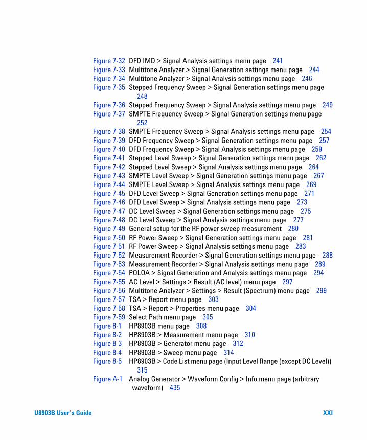
Figure 7-32 DFD IMD > Signal Analysis settings menu page 241Figure 7-33 Multitone Analyzer > Signal Generation settings menu page 244Figure 7-34 Multitone Analyzer > Signal Analysis settings menu page 246Figure 7-35 Stepped Frequency Sweep > Signal Generation settings menu page
248Figure 7-36 Stepped Frequency Sweep > Signal Analysis settings menu page 249Figure 7-37 SMPTE Frequency Sweep > Signal Generation settings menu page
252Figure 7-38 SMPTE Frequency Sweep > Signal Analysis settings menu page 254Figure 7-39 DFD Frequency Sweep > Signal Generation settings menu page 257Figure 7-40 DFD Frequency Sweep > Signal Analysis settings menu page 259Figure 7-41 Stepped Level Sweep > Signal Generation settings menu page 262Figure 7-42 Stepped Level Sweep > Signal Analysis settings menu page 264Figure 7-43 SMPTE Level Sweep > Signal Generation settings menu page 267Figure 7-44 SMPTE Level Sweep > Signal Analysis settings menu page 269Figure 7-45 DFD Level Sweep > Signal Generation settings menu page 271Figure 7-46 DFD Level Sweep > Signal Analysis settings menu page 273Figure 7-47 DC Level Sweep > Signal Generation settings menu page 275Figure 7-48 DC Level Sweep > Signal Analysis settings menu page 277Figure 7-49 General setup for the RF power sweep measurement 280Figure 7-50 RF Power Sweep > Signal Generation settings menu page 281Figure 7-51 RF Power Sweep > Signal Analysis settings menu page 283Figure 7-52 Measurement Recorder > Signal Generation settings menu page 288Figure 7-53 Measurement Recorder > Signal Analysis settings menu page 289Figure 7-54 POLQA > Signal Generation and Analysis settings menu page 294Figure 7-55 AC Level > Settings > Result (AC level) menu page 297Figure 7-56 Multitone Analyzer > Settings > Result (Spectrum) menu page 299Figure 7-57 TSA > Report menu page 303Figure 7-58 TSA > Report > Properties menu page 304Figure 7-59 Select Path menu page 305Figure 8-1 HP8903B menu page 308Figure 8-2 HP8903B > Measurement menu page 310Figure 8-3 HP8903B > Generator menu page 312Figure 8-4 HP8903B > Sweep menu page 314Figure 8-5 HP8903B > Code List menu page (Input Level Range (except DC Level))
315Figure A-1 Analog Generator > Waveform Config > Info menu page (arbitrary
waveform) 435
U8903B User’s Guide XXI

THIS PAGE HAS BEEN INTENTIONALLY LEFT BLANK.
XXII U8903B User’s Guide

List of Tables
Table 1-1 U8903B options 5Table 1-2 U8903B front panel description 6Table 1-3 U8903B rear panel description 8Table 1-4 U8903B LCD display description 11Table 1-5 System > Update menu page 14Table 1-6 System > Service > Self-Test menu page 16Table 1-7 System > Service > Options menu page 17Table 2-1 Navigation and DATA ENTRY panels description 23Table 2-2 U8903B modes description 25Table 2-3 FUNCTION panel description 28Table 2-4 GRAPH panel description 32Table 2-5 Save menu description 33Table 2-6 Peak Search > Threshold menu description 35Table 2-7 Marker menu description 36Table 2-8 Marker > Marker - menu description 38Table 2-9 Marker > Harmonics menu description 39Table 2-10 Save menu description 40Table 2-11 SYSTEM panel description 43Table 2-12 Preset menu description 45Table 2-13 Utility menu description (generator and analyzer mode) 46Table 2-14 Utility menu description (graph analysis mode) 47Table 2-15 Error Info menu description 49Table 2-16 Utility menu description (generator and analyzer mode) 50Table 2-17 System > I/O > LAN Settings menu description 51Table 2-18 System > Service menu description 53Table 2-19 System > Settings menu description 54Table 2-20 System > HP8903B Config menu description 56Table 2-21 System > Aux Output menu description 58Table 2-22 Navigation and DATA ENTRY panels description 60Table 2-23 Save menu description 61Table 2-24 Save menu description 62Table 3-1 Analog Generator menu description 67Table 3-2 Analog Generator > Waveform Config menu description (sine
waveform) 68
U8903B User’s Guide XXIII

Table 3-3 Analog Generator > Waveform Config menu description (variable phase waveform) 69
Table 3-4 Analog Generator > Waveform Config menu description (variable phase waveform) 70
Table 3-5 Analog Generator > Waveform Config menu description (SMPTE IMD waveforms) 72
Table 3-6 Analog Generator > Waveform Config menu description (IEC 60118 waveform) 73
Table 3-7 Analog Generator > Waveform Config menu description (IEC 60268 waveform) 74
Table 3-8 Analog Generator > Waveform Config menu description (Gaussian noise) 75
Table 3-9 Analog Generator > Waveform Config menu description (Rectangular noise) 76
Table 3-10 Analog Generator > Waveform Config menu description (Pink noise) 77
Table 3-11 Analog Generator > Waveform Config menu description (square waveform) 78
Table 3-12 Analog Generator > Waveform Config menu description (DC signal) 79Table 3-13 Analog Generator > Waveform Config menu description (arbitrary
waveform) 81Table 3-14 Analog Generator > Waveform Config menu description (multitone
waveform) 82Table 3-15 Analog Generator > Waveform Config > Custom menu description
(multitone waveform) 84Table 3-16 Analog Generator > Waveform Config menu description (DTMF) 87Table 3-17 Dial menu page description 88Table 3-18 DTMF tone mapping 89Table 3-19 Analog Generator > Output Config menu description 90Table 3-20 Analog Generator > References menu description 92Table 4-1 Analog Analyzer menu description 95Table 4-2 Analog Analyzer > Functions menu description 96Table 4-3 Analog Analyzer > Functions > Frequency menu description 98Table 4-4 Analog Analyzer > Functions > AC Voltage menu description 100Table 4-5 Analog Analyzer > Functions > DC Voltage menu description 102Table 4-6 Analog Analyzer > Functions > THD+N Ratio menu description 105Table 4-7 Analog Analyzer > Functions > THD+N Level menu description 106Table 4-8 Analog Analyzer > Functions > SINAD menu description 109
XXIV U8903B User’s Guide

Table 4-9 Analog Analyzer > Functions > THD Ratio menu description 112Table 4-10 Analog Analyzer > Functions > THD Level menu description 114Table 4-11 Analog Analyzer > Functions > SMPTE IMD menu description 118Table 4-12 Analog Analyzer > Functions > DFD measurements menu
description 119Table 4-13 Analog Analyzer > Functions > SNR menu description 122Table 4-14 Analog Analyzer > Functions > SNR (Fast) menu description 124Table 4-15 Analog Analyzer > Functions > Phase menu description 126Table 4-16 Analog Analyzer > Functions > X-Talk menu description 128Table 4-17 Analog Analyzer > Filter Config menu description 130Table 4-18 Analog Analyzer > Filter Config > Notch Filter menu description 132Table 4-19 Analog Analyzer > Meas Config menu description 133Table 4-20 Analog Analyzer > Input Config menu description 135Table 4-21 Analog Analyzer > Wave File menu description 137Table 4-22 Analog Analyzer > Statistics menu description 139Table 5-1 Graph Analysis menu description 143Table 5-2 Graph Analysis > Graph Settings menu description 145Table 5-3 Graph Analysis > Axis Settings menu description 147Table 5-4 Graph Analysis > Trace Settings menu description 149Table 5-5 Graph Analysis > Trace Settings > Memory menu description 151Table 5-6 Graph Analysis > Trace Settings > Math menu description 152Table 5-7 Graph Analysis > Trace Settings > Persistence menu description 153Table 5-8 Graph Analysis > Harm Settings menu description (Harmonics
display) 159Table 5-9 Graph Analysis > Measurement menu description 162Table 5-10 Graph Analysis > Measurement > Measurement 1/Measurement 2
menu description 163Table 6-1 Sweep Parameter menu description 167Table 6-2 Sweep Parameter > Points Settings menu description 168Table 6-3 Sweep Parameter > Channels menu description 170Table 6-4 Sweep > Plot View menu description 171Table 6-5 Sweep > Plot View > Axis Settings menu description 172Table 6-6 Sweep > Plot View > Plot Settings menu description 173Table 6-7 Sweep > Edit Points menu description 175Table 7-1 Test Application menu description 180Table 7-2 TSA > Project menu description 181Table 7-3 TSA > Project > Properties menu description 182Table 7-4 TSA > Project > Test menu description 183
U8903B User’s Guide XXV

Table 7-5 TSA > Project > Test > IO Configuration menu description 184Table 7-6 TSA > Project > Test > IO Configuration > Output Configuration menu
description 186Table 7-7 TSA > Project > Test > IO Configuration > Input Configuration menu
description 188Table 7-8 TSA > Project > Test > IO Configuration > Properties menu
description 190Table 7-9 Sub-step menu description 191Table 7-10 Prompt sub-step settings menu description 193Table 7-11 Send SCPI sub-step settings menu description 195Table 7-12 TSA > Project > Test > Measurement menu description 197Table 7-13 TSA > Project > Test > Measurement > Properties menu
description 199Table 7-14 TSA > Project > Test > AC Level > Settings > Signal Generation menu
description 202Table 7-15 TSA > Project > Test > AC Level > Settings > Signal Analysis menu
description 203Table 7-16 Frequency > Signal Generation settings menu description 207Table 7-17 Frequency > Signal Analysis settings menu description 208Table 7-18 Phase > Signal Generation settings menu description 211Table 7-19 Phase > Signal Analysis settings menu description 212Table 7-20 SNR > Signal Generation settings menu description 215Table 7-21 SNR > Signal Analysis settings menu description 217Table 7-22 THD+N > Signal Generation settings menu description 222Table 7-23 THD+N > Signal Analysis settings menu description 223Table 7-24 DC Level > Signal Generation settings menu description 227Table 7-25 DC Level > Signal Analysis settings menu description 228Table 7-26 Crosstalk > Signal Generation settings menu description 231Table 7-27 Crosstalk > Signal Analysis settings menu description 232Table 7-28 SMPTE IMD > Signal Generation settings menu description 235Table 7-29 SMPTE IMD > Signal Analysis settings menu description 237Table 7-30 DFD IMD > Signal Generation settings menu description 240Table 7-31 DFD IMD > Signal Analysis settings menu description 241Table 7-32 Multitone Analyzer > Signal Generation settings menu description 244Table 7-33 Multitone Analyzer > Signal Analysis settings menu description 246Table 7-34 Stepped Frequency Sweep > Signal Generation settings menu
description 248
XXVI U8903B User’s Guide

Table 7-35 Stepped Frequency Sweep > Signal Analysis settings menu description 250
Table 7-36 SMPTE Frequency Sweep > Signal Generation settings menu description 253
Table 7-37 SMPTE Frequency Sweep > Signal Analysis settings menu description 254
Table 7-38 DFD Frequency Sweep > Signal Generation settings menu description 257
Table 7-39 DFD Frequency Sweep > Signal Analysis settings menu description 259
Table 7-40 Stepped Level Sweep > Signal Generation settings menu description 262
Table 7-41 Stepped Level Sweep > Signal Analysis settings menu description 264Table 7-42 SMPTE Level Sweep > Signal Generation settings menu
description 268Table 7-43 SMPTE Level Sweep > Signal Analysis settings menu description 269Table 7-44 DFD Level Sweep > Signal Generation settings menu description 272Table 7-45 DFD Level Sweep > Signal Analysis settings menu description 273Table 7-46 DC Level Sweep > Signal Generation settings menu description 276Table 7-47 DC Level Sweep > Signal Analysis settings menu description 277Table 7-48 RF Power Sweep > Signal Generation settings menu description 282Table 7-49 RF Power Sweep > Signal Analysis settings menu description 284Table 7-50 Measurement Recorder > Signal Generation settings menu
description 288Table 7-51 Measurement Recorder > Signal Analysis settings menu
description 289Table 7-52 POLQA > Signal Generation and Analysis settings menu
description 294Table 7-53 TSA > Project > Test > Measurement > Settings > Result (bar chart)
menu description 297Table 7-54 TSA > Project > Test > Measurement > Settings > Result (graph) menu
description 299Table 7-55 TSA > Report menu description 303Table 7-56 TSA > Report > Properties menu description 304Table 8-1 U8903B LCD display description 309Table 8-2 HP8903B > Measurement menu description 310Table 8-3 HP8903B unit charts 311Table 8-4 HP8903B > Generator menu description 312
U8903B User’s Guide XXVII

Table 8-5 HP8903B > Sweep menu description 315Table 8-6 HP8903B special function code list description 316Table 9-1 Measurement category definitions 333Table A-1 FUNCTION panel description 336Table A-2 GRAPH panel menu tree description 337Table A-3 SYSTEM panel menu tree description 339Table A-4 Analog generator menu tree description 344Table A-5 Analog analyzer menu tree description 349Table A-6 Graph analysis menu tree description 362Table A-7 Sweep function menu tree description 367Table A-8 Save menu tree description 370Table A-9 Recall menu tree description 371Table A-10 Test sequence menu tree description 372Table A-11 Measurement settings > AC Level menu tree description 383Table A-12 Measurement settings > Frequency menu tree description 384Table A-13 Measurement settings > Phase menu tree description 386Table A-14 Measurement settings > SNR menu tree description 387Table A-15 Measurement settings > THD+N menu tree description 389Table A-16 Measurement settings > DC Level menu tree description 392Table A-17 Measurement settings > Crosstalk menu tree description 393Table A-18 Measurement settings > SMPTE IMD menu tree description 394Table A-19 Measurement settings > DFD IMD menu tree description 395Table A-20 Measurement settings > Multitone Analyzer menu tree
description 397Table A-21 Measurement settings > Stepped Frequency Sweep menu tree
description 399Table A-22 Measurement settings > SMPTE Frequency Sweep menu tree
description 402Table A-23 Measurement settings > DFD Frequency Sweep menu tree
description 404Table A-24 Measurement settings > Stepped Level Sweep menu tree
description 406Table A-25 Measurement settings > SMPTE Level Sweep menu tree
description 409Table A-26 Measurement settings > DFD Level Sweep menu tree description 411Table A-27 Measurement settings > DC Level Sweep menu tree description 413Table A-28 Measurement settings > RF Power Sweep menu tree description 416
XXVIII U8903B User’s Guide
Table A-29 Measurement settings > Measurement Recorder menu tree description 420
Table A-30 Measurement settings > POLQA menu tree description 423Table A-31 Measurement Results > Bar chart menu tree description 426Table A-32 Measurement results > Graph menu tree description 427Table A-33 HP8903B menu tree description 430Table A-34 Analog analyer units of the meaurement function returned values 432Table A-35 Unit conversion formula 433Table A-36 Allowable range for arbitrary file parameters 436Table A-37 Analog generator default settings 441Table A-38 Analog analyzer default settings 442Table A-39 Sweep default settings 446Table A-40 HP8903B default settings 447Table A-41 System default settings 448
U8903B User’s Guide XXIX

THIS PAGE HAS BEEN INTENTIONALLY LEFT BLANK.
XXX U8903B User’s Guide

U8903B Audio AnalyzerUser’s Guide
1Getting Started
Introduction 2
LXI Standard 1.4 Compliant Audio Analyzer 2
Installation and Configuration 3Initial inspection 3Ventilation 3Rack mounting 3
Standard Shipped Items 4
Optional Accessories 4
U8903B Options 5
Product at a Glance 6Front panel 6Rear panel 8LCD display 10
Getting Started 12Power on the U8903B 12Preset the U8903B 12Access the help mode 13Update the U8903B 14Perform self-test 16Add or remove U8903B options 17
This chapter teaches you how to set up the U8903B for the first time. A summary of all the features of the U8903B is also given.
1Agilent Technologies
1 Getting Started Introduction
Introduction
The U8903B is a digital signal processing (DSP)- based audio measurement system with a frequency measurement range of 10 Hz to 96 kHz or 1.5 MHz depending on the installed option. The U8903B basic configuration has two channels of analog audio generator and two channels of analog audio analyzer.
The standard option for the U8903B audio analyzer is Option STD. The U8903B can be further expanded with additional analog analyzer channels. Refer to “U8903B Options” on page 5 for more information on the available U8903B options.
The U8903B is capable of performing a wide range of audio parameter measurements on both analog audio and digital audio interfaces. Up to four measurement functions can be performed simultaneously on the analog audio. The U8903B also supports industrial standard instrument connectivity such as GPIB, USB, and LAN. In addition, the U8903B is equipped with frequency, phase, time, and FFT graph analysis, as well as sweep capability for frequency and amplitude.
The U8903B also allows you to create test sequences. Refer to Chapter 7, “Test Sequence Application” for more information.
To search for firmware updates for the U8903B, go to the Agilent U8903B firmware update Web site at www.agilent.com/find/audioanalyzer_firmware.
LXI Standard 1.4 Compliant Audio Analyzer
The U8903B audio analyzer is a LAN eXtension for Instrumentation (LXI) Standard 1.4 compliant (Standard Core) instrument, developed using LXI Technology. LXI is an instrument standard for devices that use the Ethernet (LAN) as their primary communication interface.
Hence, it is an easy- to- use instrument especially with the usage of an integrated Web browser that provides a convenient way to configure the instrument’s functionality.
2 U8903B User’s Guide

Getting Started 1 Installation and Configuration
Installation and Configuration
Initial inspection
When you receive your U8903B, inspect the unit for any obvious damage such as broken terminals or cracks, dents, and scratches on the chassis that may occur during shipment. If any damage is found, notify the nearest Agilent Sales Office immediately.
Keep the original packaging in case the U8903B has to be returned to Agilent in the future. If you return the U8903B for service, attach a tag identifying the owner and model number. Also, include a brief description of the problem.
Ventilation
The U8903B can operate within the temperature range of 0 °C to 55 °C. The U8903B is cooled by drawing air through the sides and bottom at the front of the U8903B, and exhausting it through the ventilation holes on the sides and top at the rear of the U8903B. The U8903B must be installed in a location that allows sufficient space at the top, sides, and rear for adequate air circulation.
Rack mounting
The U8903B can be mounted in a standard 19- inch rack. Rackmount kits are available as Option 908. Support rails are also required for rack mounting. These are normally supplied with the rack and are not included with the rackmount options.
If you are installing an instrument on top of the U8903B, ensure that the instrument does not obstruct the ventilation holes at the top of the U8903B. If required, use a filler panel above the U8903B to ensure adequate space for air circulation.
U8903B User’s Guide 3

1 Getting Started Standard Shipped Items
Standard Shipped Items
Verify that you have received the following items. If anything is missing or damaged, please contact the nearest Agilent Sales Office.
• U8903B Audio Analyzer
• Power cord
• LAN cable
• USB cable
• Agilent U8903B Audio Analyzer Quick Start Guide
• Agilent U8903B Audio Analyzer Product Reference CD- ROM
• Certificate of Calibration
Optional Accessories
The following accessories are available for purchase separately.
• Male BNC to male BNC cable (1.2 m)
• Male BNC to male RCA cable (2 m)
• Male XLR to female XLR cable (2 m)
• Male XLR to male BNC cable (0.26 m)
• Female XLR to male BNC cable (0.26 m)
• BNC accessory kit
• Rackmount kit
• Digital serial interface cable
4 U8903B User’s Guide

Getting Started 1 U8903B Options
U8903B Options
Table 1-1 U8903B options
Option Description
U8903B-STD• 2 channels (analog generator)• 2 channels (analog analyzer)
U8903B-AN4• 2 channels (analog generator)• 4 channels (analog analyzer)
U8903B-AN8• 2 channels (analog generator)• 8 channels (analog analyzer)
U8903B-AUX• 2 monitor outputs• 1 auxiliary output
N3431ASoftware option to increase the bandwidth to 1.5 MHz (fixed perpetual license).
This is only available for channel 1 and channel 2 analog analyzer.
N3432ASoftware option to include Perceptual Objective Listening Quality Analysis (POLQA) measurement (fixed perpetual license).
U8903B User’s Guide 5

1 Getting Started Product at a Glance
Product at a Glance
Front panel
Figure 1-1 U8903B front panel
SYSTEM
Local
System
Utility
Preset
Help
Macro
L o c k / U n l o c k
GRAPH
PeakSearch
Marker
Scale
Zoom
Edi t Zoom
FUNCTION
Interface GeneratorAnalyzer
SweepGraph
FullScreen
Display
ShortcutShortcut1 2
Menu
RUN CONTROL
OnOff Stop All
Enter
DATA ENTRY
1 2 3
4 5 6
7 8 9
0
ABC DEF
GHI JKL MNO
PQRS TUV WXYZ
Bk Sp ESC Shift
�� U8 903BAudio Analyzer
ANALYZERCHANNEL 1 CHANNEL 2
200 VpkMax
200 VpkMax
GENERATORCHANNEL 1 CHANNEL 2
1 2 3 4 5 6 7 8
9101112
Table 1-2 U8903B front panel description
Item Description
1 LCD display
Provides information on the current function including status indicators, settings, and error messages.
Refer to “LCD display” on page 10 for more information.
2 Softkeys 1 to 7Activates the functions displayed on the LCD display next to the respective soft keys.
3 Navigation and DATA ENTRY panelsThe navigation and DATA ENTRY panels consist of the arrow keys, Enter key, knob, and data entry keys. Refer to “Navigation and DATA ENTRY panels” on page 23 for more information.
6 U8903B User’s Guide

Getting Started 1 Product at a Glance
4 Menu key
Displays the available U8903B mode of operation.
• Standard View• Test Seq App• HP8903B
5 FUNCTION panel Enables access to the U8903B main functions.
6 Run control panel
Press On/Off to turn on or off signal generation or measurements for the selected generator or analyzer channel respectively.
Press On/Off to start or stop the graph generation.
Press On/Off to start or stop the sweep.
Press On/Off to start or stop the test sequence.
Press Stop All to stop all generator and test sequence operations.
Refer to “RUN CONTROL panel” on page 60 for more information.
7 GRAPH panelEnables access to the U8903B commonly used graph functions. Refer to “GRAPH panel” on page 32 for more information.
8 SYSTEM panelEnables access to the U8903B system functions. Refer to “SYSTEM panel” on page 43 for more information.
9 Headphone jackThe headphone jack can be operated in stereo or mono mode. Refer to “Input Configuration” on page 135 for more information.
10 USB port Allows an external USB flash storage to be connected to the U8903B.
11 Analog analyzer inputReceives analog audio signal using a female XLR input connector for balanced signal and a female BNC input connector for unbalanced signal. The input connectors are available for each channel.
12 Analog generator outputOutputs analog audio signal using a male XLR output connector for balanced signal and a female BNC output connector for unbalanced signal. The output connectors are available for each channel.
13 Power key Turns on or off the U8903B.
Table 1-2 U8903B front panel description (continued)
Item Description
U8903B User’s Guide 7

1 Getting Started Product at a Glance
Rear panel
Figure 1-2 U8903B rear panel
1 2 3 4 5 6
78911 10
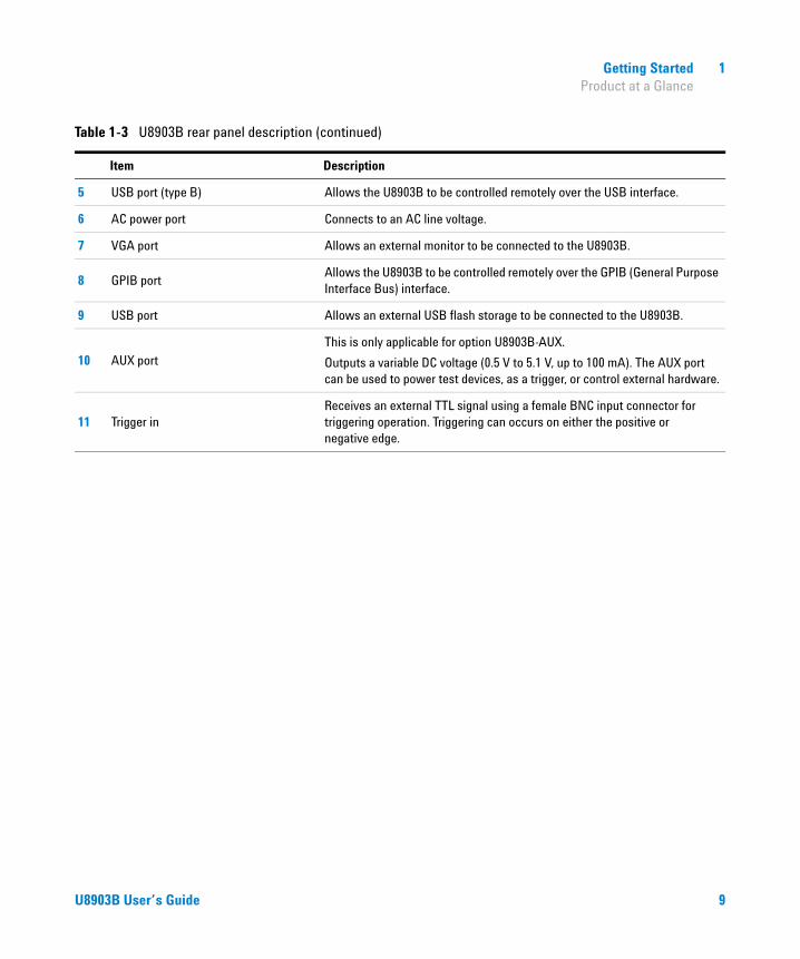
Table 1-3 U8903B rear panel description
Item Description
1 Monitor 1
This is only applicable for option U8903B-AUX.
Outputs a scaled signal of the analog analyzer channels 1, 3, 5, and 7 input signals. The scaled signal can then be connected to an external amplifier or other measurement instruments.
2 Monitor 2
This is only applicable for option U8903B-AUX.
Outputs a scaled signal of the analog analyzer channels 2, 4, 6, and 8 input signals. The scaled signal can then be connected to an external amplifier or other measurement instruments.
3 Analog analyzer input (channels 3 to 8)
This is only applicable for options U8903B-AN4 and U8903B-AN6.
Receives analog audio signal using a female XLR input connector for balanced input and a female BNC input connector for unbalanced input. There are up to 6 analog input channels available. The input connectors are available for each channel.
4 LAN port Allows the U8903B to be controlled remotely over the LAN interface.
8 U8903B User’s Guide
Getting Started 1 Product at a Glance
5 USB port (type B) Allows the U8903B to be controlled remotely over the USB interface.
6 AC power port Connects to an AC line voltage.
7 VGA port Allows an external monitor to be connected to the U8903B.
8 GPIB portAllows the U8903B to be controlled remotely over the GPIB (General Purpose Interface Bus) interface.
9 USB port Allows an external USB flash storage to be connected to the U8903B.
10 AUX port
This is only applicable for option U8903B-AUX.
Outputs a variable DC voltage (0.5 V to 5.1 V, up to 100 mA). The AUX port can be used to power test devices, as a trigger, or control external hardware.
11 Trigger inReceives an external TTL signal using a female BNC input connector for triggering operation. Triggering can occurs on either the positive or negative edge.
Table 1-3 U8903B rear panel description (continued)
Item Description
U8903B User’s Guide 9
1 Getting Started Product at a Glance
LCD display
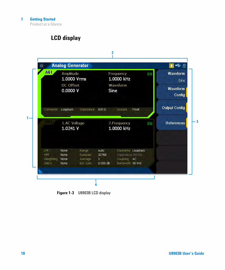
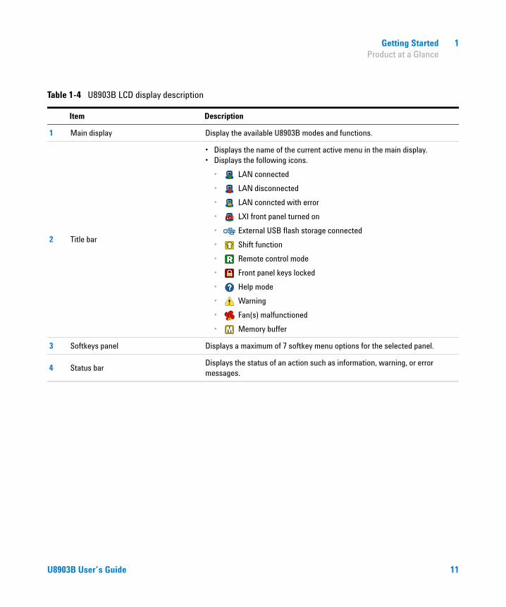
Figure 1-3 U8903B LCD display
2
31
4
10 U8903B User’s Guide
Getting Started 1 Product at a Glance
Table 1-4 U8903B LCD display description
Item Description
1 Main display Display the available U8903B modes and functions.
2 Title bar
• Displays the name of the current active menu in the main display.• Displays the following icons.
• LAN connected
• LAN disconnected
• LAN conncted with error
• LXI front panel turned on
• External USB flash storage connected
• Shift function
• Remote control mode
• Front panel keys locked
• Help mode
• Warning
• Fan(s) malfunctioned
• Memory buffer
3 Softkeys panel Displays a maximum of 7 softkey menu options for the selected panel.
4 Status barDisplays the status of an action such as information, warning, or error messages.
U8903B User’s Guide 11
1 Getting Started Getting Started
Getting Started
Power on the U8903B
Connect one end of the power cord to the U8903B rear panel AC power inlet and the other end to an AC voltage source. The U8903B will automatically adjust to the correct line voltage in the range of 100 VAC to 240 VAC.
Preset the U8903B
A preset will set the U8903B to a default state. It does not affect the I/O configuration, calibration data, system configurations (time, date, model number, and serial number), and license information. Refer to “Appendix O: U8903B Default Settings” on page 441 for more information.
To preset the U8903B, you can perform either one of the following steps.
• Send the *RST, SYSTem:PRESet or SYSTem:RESet[:MODE] SCPI commands from the PC via the USB, GPIB, or LAN interface.
• Press on the SYSTEM panel.Preset
NOTE For more information on preset, refer to “SYSTEM panel” on page 43.
12 U8903B User’s Guide

Getting Started 1 Getting Started
Access the help mode
The U8903B help mode provides you quick access to the operating information by displaying the description of all the front panel keys and current softkeys.
To activate or deactivate the U8903B help mode, press on the
DATA ENTRY panel and on the SYSTEM panel.
An example of a help mode is shown in Figure 1- 4. The help mode icon will appear at the top- right of the title bar. Refer to Figure 1- 4 for more information on the help mode icon. Press the front panel keys or the current menu page softkeys to display the respective information.
Figure 1-4 Help mode
Shift
Utility
Help
NOTE When the U8903B help mode is activated, the front panel keys will not execute their normal functions when pressed.
U8903B User’s Guide 13
1 Getting Started Getting Started
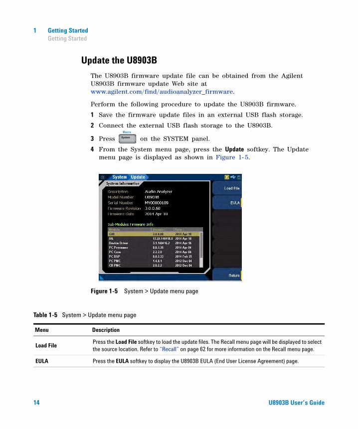
Update the U8903B
The U8903B firmware update file can be obtained from the Agilent U8903B firmware update Web site at www.agilent.com/find/audioanalyzer_firmware.
Perform the following procedure to update the U8903B firmware.
1 Save the firmware update files in an external USB flash storage.
2 Connect the external USB flash storage to the U8903B.
3 Press on the SYSTEM panel.
4 From the System menu page, press the Update softkey. The Update menu page is displayed as shown in Figure 1- 5.
Figure 1-5 System > Update menu page
System
Macro
Table 1-5 System > Update menu page
Menu Description
Load FilePress the Load File softkey to load the update files. The Recall menu page will be displayed to select the source location. Refer to “Recall” on page 62 for more information on the Recall menu page.
EULA Press the EULA softkey to display the U8903B EULA (End User License Agreement) page.
14 U8903B User’s Guide

Getting Started 1 Getting Started
5 Press the Load File softkey and the recall menu page is displayed to enable you to select the source location.
6 Select the firmware file to be updated, and press the Recall softkey as shown in Figure 1- 6. Refer to “Recall” on page 62 for more information on the Recall menu page.
Figure 1-6 Recall menu page
NOTE The System menu page is only available in the Standard mode. Refer to “Menu key” on page 25 for more information on the U8903B available modes.
CAUTION The firmware update process may take 20 minutes to 40 minutes to complete.
DO NOT power off the U8903B.
U8903B User’s Guide 15
1 Getting Started Getting Started
Perform self-test
Perform the following procedure to run the U8903B self- test.
1 Press on the SYSTEM panel.
2 From the System menu page, press the Service softkey.
3 From the Service menu page, press the Self-Test softkey. The Self- Test menu page is displayed as shown in Figure 1- 7.
4 Press the Customize Test softkey to select the desired tests.
5 Press the Run Test softkey to run the slected tests.
Figure 1-7 System > Service > Self-Test menu page
System
Macro
Table 1-6 System > Service > Self-Test menu page
Menu Description
Customize TestPress the Customize softkey to select or deselect the desired tests.
• LAN Test• Card Self Test
Run Test Press the Run Test softkey to run the selected tests.
Clear ResultPress the Clear Result softkey to clear the previous self-test results. The self-test results are saved in the system memory.
16 U8903B User’s Guide

Getting Started 1 Getting Started
Add or remove U8903B options
Perform the following procedure to add U8903B options.
1 Press on the SYSTEM panel.
2 From the System menu page, press the Service softkey.
3 From the Service menu page, press the Options softkey. The Options menu page is displayed as shown in Figure 1- 8.
Figure 1-8 System > Service > Options menu page
NOTE The System menu page is only available in the Standard mode. Refer to “Menu key” on page 25 for more information on the U8903B available modes.
System
Macro
Table 1-7 System > Service > Options menu page
Menu Description
Add OptionPress the Add Option softkey to load the U8903B option file. The Recall menu page will be displayed to select the source location.
Remove Option Press the Remove Option softkey to remove the selected U8903B option.
U8903B User’s Guide 17

1 Getting Started Getting Started
4 Press the Add option softkey and the Recall menu page is displayed to enable you to select the U8903B option file.
5 Select the U8903B option file to be loaded, and press the Recall softkey as shown in Figure 1- 6.
Figure 1-9 Recall menu page
Perform the following procedure to remove U8903B options.
1 Select the U8903B option to be removed from the list.
2 Press the Remove option softkey to remove the U8903B option as shown in Figure 1- 8.
NOTE Restart the U8903B after adding a new U8903B option file.
NOTE The System menu page is only available in the Standard mode. Refer to “Menu key” on page 25 for more information on the U8903B available modes.
18 U8903B User’s Guide
U8903B Audio AnalyzerUser’s Guide
2Operation and Features
Test Capabilities 20
U8903B Block Diagram 21Analog audio interface 21
Navigation and DATA ENTRY panels 23
Menu key 25Standard View 26Test Sequence Application (Test Seq App) 27HP8903B 27
FUNCTION panel 28Full Screen 29Display mode 30
GRAPH panel 32Peak Search 33Marker 36Scale 40Zoom 41Edit zoom 42
SYSTEM panel 43Preset 44Utility 46System 48
RUN CONTROL panel 60
Save and Recall 61Save 61Recall 62
This chapter describes the test capabilities, key features, and the front panel operation of the U8903B.
19Agilent Technologies

2 Operation and Features Test Capabilities
Test Capabilities
The U8903B is capable of testing a broad range of audio- related devices and components for research and development, manufacturing, and quality assurance applications. Examples of the products that can be tested are listed follows.
• Multichannel home theater systems
• Audio amplifiers, as a complete product or at the component level
• Portable audio playback devices such as MP3 players
• Speakers (require third party accessories such as microphones and power amplifiers)
• PC audio cards
• Audio components
The U8903B performs the following two basic functions.
• Audio signal generation
• Audio signal analysis
The U8903B basic configuration has two channels of analog generator and two channels of analog analyzer which enables the U8903B to test devices with stereo capability.
20 U8903B User’s Guide

Operation and Features 2 U8903B Block Diagram
U8903B Block Diagram
Analog audio interface
A simplified U8903B block diagram is shown as follows.
Figure 2-1 U8903B analog generator block diagram
Signal generation
The Digital Signal Processing (DSP) generates all the required waveforms, except for square wave, digitally. The digital waveform data is streamed realtime into the 24- bit Digital- to- Analog Converter (DAC) where it is converted to voltage and sent to the output conditioning block to be amplified or attenuated to the required amplitude. Finally, the waveform is routed through either the balanced (XLR) or unbalanced (BNC) output signal connectors to the Unit- Under- Test (UUT). The output can also be fully floating or have the output grounded to the instrument ground. There is also a loopback facility where the analog generator can be connected onto the systems internal analog bus and routed to the analog analyzer.
GENERATOR
DAC FILTER RANGING
ISOLATED GROUND
LOOPBACK
BNC
XLR
U8903B User’s Guide 21
2 Operation and Features U8903B Block Diagram
Figure 2-2 U8903B analog analyzer block diagram
Measurement
An audio signal can enter the analog analyzer through either the balanced (XLR) or unbalanced (BNC) input signal connector. There is also a loopback facility where the analog generator can be connected onto the systems internal analog bus and routed to the analog analyzer.
From the input connector, the signal passes through the AC/DC coupling circuit. If AC coupling is selected, the DC component is blocked and only the AC component of the signal passes through. However, if DC coupling is selected, the entire signal passes through.
The attenuators, buffer, gain, and Common Mode Rejection (CMR) conditions the signal to as close to the full scale of the Analog- to- Digital converter (ADC) as possible, optimizing the measurement dynamic range.
There are two separate ADCs in the analog analyzer. The low bandwidth ADC is designed for best performance in the audio bandwidth and beyond. The high bandwidth ADC is designed to give high resolution measurements up to 1.5 MHz.
The default input impedance is 100 kΩ for unbalanced signals or 200 kΩ for balanced signals. Terminations of 600 Ω or 300 Ω can also be applied. The 600 Ω termination can tolerate up to 1.5 W and the 300 Ω termination can tolerate up to 3 W.
ANALYZER
ADCFILTERRANGING
LOOPBACK
BNC
XLR
600 Ω 300 Ω 200 kΩTermination
AC/DC Coupling
100 kΩ
22 U8903B User’s Guide

Operation and Features 2 Navigation and DATA ENTRY panels
Navigation and DATA ENTRY panels
The navigation and DATA ENTRY panels are used to navigate and set or modify the parameter values.
Figure 2-3 Navigation and DATA ENTRY panels
Enter
DATA ENTRY
1 2 3
4 5 6
7 8 9
0
ABC DEF
GHI JKL MNO
PQRS TUV WXYZ
Bk Sp ESC Shift
2
1
3
4
5
678
Table 2-1 Navigation and DATA ENTRY panels description
Item Description
1 KnobRotate the knob to increase or decrease a numeric value, change a highlighted digit or character, or step through lists or items in a row.
2 Arrow keys
Use the arrow keys to highlight or navigate the editable items on the LCD display for editing.
In HP8903B mode, press the up and down arrow keys to increment/decrement the frequency and amplitude values.
U8903B User’s Guide 23

2 Operation and Features Navigation and DATA ENTRY panels
3 Enter key Press to confirm an entry.
4 Numeric keys
Use the numeric keys to enter alphanumeric data by using the number keys and decimal point, or select the channel number.
In DTMF single mode, press to generate the ‘*’ DTMF tone.
5 Numeric sign key
Press to specify a positive or negative value. For a negative value, press to enter the negative sign before a numeric value.
In DTMF single mode, press to generate the ‘#’ DTMF tone.
6 Shift key
Press prior to pressing a shifted function key. The shifted functions are printed in Blue on top of the front panel keys. Refer to “GRAPH panel” on page 32 and “SYSTEM panel” on page 43 for more information.
7 Escape key Press to cancel a selected action.
8 Back space key Press to delete the character to the left of the cursor.
Table 2-1 Navigation and DATA ENTRY panels description
Item Description
Enter
Shift
ESC
Bk Sp
24 U8903B User’s Guide

Operation and Features 2 Menu key
Menu key
Press to display the list of available U8903B main modes of operation. Select the desired mode from the drop- down list as shown in Figure 2- 4.
Figure 2-4 U8903B mode selection
The U8903B modes are listed as follows.
Menu
Table 2-2 U8903B modes description
Mode Description
Standard View The Standard View mode is the default mode for the U8903B. Refer to “Standard View” on page 26 for more information.
Test Seq App Refer to “Test Sequence Application (Test Seq App)” on page 27 for more information.
HP8903B Refer to “HP8903B” on page 27 for more information.
U8903B User’s Guide 25
2 Operation and Features Menu key
Standard View
Press and select Standard View to access the standard view menu page. In the standard view, you can perform signal analysis, graph analysis, sweep function, and system configurations. The Standard View mode is the default mode for the U8903B.
Signal analysis
Press on the FUNCTION panel to switch between audio generator or audio analyzer mode. Refer to Chapter 3, “Audio Generator Functions” and Chapter 4, “Audio Analyzer Measurement Functions” for more information on the respective configurations.
Graph analysis
Press on the FUNCTION panel to access the graph analysis mode. Refer to Chapter 5, “Graph Analysis” for more information on the graph analysis mode configurations.
Sweep function
Press on the FUNCTION panel to access the U8903B sweep parameter and the configurations. Refer to Chapter 6, “Sweep Function” for more information on the sweep configurations.
System configurations
Press on the SYSTEM panel to access the U8903B system configurations. You can view the error messages, configure I/O settings, update the U8903B, self- tests, configure the U8903B settings, configure the HP8903B mode settings, and others. Refer to “System” on page 48 for more information on the system configurations.
Menu
GeneratorAnalyzer
Graph
Sweep
System
Macro
26 U8903B User’s Guide

Operation and Features 2 Menu key
Test Sequence Application (Test Seq App)
Press and select Test Seq App to access the test sequence application mode. The test sequence application mode allows you to perform a series of automated measurements. Refer to Chapter 7, “Test Sequence Application” for more information.
HP8903B
Press and select HP8903B to access the HP8903B mode. The HP8903B mode emulates the HP8903B audio analyzer behavior. Refer to Chapter 8, “HP8903B” for more information.
Sweep
Menu
U8903B User’s Guide 27

2 Operation and Features FUNCTION panel
FUNCTION panelThe FUNCTION panel provides quick access to the U8903B main functions.
Table 2-3 FUNCTION panel description
FUNCTION panel Key Description
Interface Reserved for future expansion.
Generator|Analyzer
Press to switch between the generator or analyzer mode.
Refer to Chapter 3, “Audio Generator Functions” and Chapter 4, “Audio Analyzer Measurement Functions” for more information.
GraphPress to access the graph analysis mode.
Refer to Chapter 5, “Graph Analysis” for more information.
Sweep
Press to access the sweep function mode.
Refer to Chapter 6, “Sweep Function” for more information.
Full Screen
Press to maximize the graph view to the full display size.
This function is only applicable in the graph analysis mode. Refer to “Full Screen” on page 29 for more information.
Display
Press to switch among the 2-panel view, 4-panel view, or 10-panel view in the analyzer and generator mode.
Press to switch between the single panel view and 2-panel view in the graph analysis mode.
Refer to “Display mode” on page 30 for more information.
Shortcut 1Customizable shortcut key. Refer to Table 2-19 for more information.
Shortcut 2Customizable shortcut key. Refer to Table 2-19 for more information.
FUNCTION
Interface GeneratorAnalyzer
SweepGraph
FullScreen
Display
ShortcutShortcut1 2
GeneratorAnalyzer
Graph
Sweep
FullScreen
Display
Display
28 U8903B User’s Guide

Operation and Features 2 FUNCTION panel
Full Screen
The full screen graph display is displayed as shown in Figure 2- 5. To exit from the full screen graph display, press .
Figure 2-5 Full screen graph display
NOTE The full screen function is only available in the graph analysis mode.
FullScreen
U8903B User’s Guide 29

2 Operation and Features FUNCTION panel
Display mode
The U8903B allows you to display up to ten panels on the main display in the analyzer and generator mode.
Figure 2-6 4-panel view
Figure 2-7 10-panel view
30 U8903B User’s Guide

Operation and Features 2 FUNCTION panel
The U8903B allows you to display up to two panels on the main display in the graph analysis mode.
Figure 2-8 Graph analysis mode 2-panel view
U8903B User’s Guide 31
2 Operation and Features GRAPH panel
GRAPH panel
The graph panel provides quick access to the commonly used graph functions. Refer to Chapter 5, “Graph Analysis” for more information on the graph analysis mode.
NOTE Some keys have a shifted function printed above the keys. Press on the DATA ENTRY panel before pressing the desired key with the shifted function.
Shift
Table 2-4 GRAPH panel description
GRAPH panel Key Description
Peak Search
Press to display the peak search menu page, and place the selected marker on the trace point at the maximum Y-axis value for the marker trace. Refer to “Peak Search” on page 33 for more information.
Marker
Press to access the marker softkeys that select the current and reference markers and turns them on and off.
You may also move the markers, display the marker measurement data, and display the section of the graph based on the selected marker position.
Refer to “Marker” on page 36 for more information.
Print (Shift + Marker)
Press and to print the current display to a file. Refer to “Save” on page 61 for more information.
Scale
Press to perform autoscaling to automatically scale the display according to the signal, or to autoscale the X-axis or Y-axis. Refer to “Scale” on page 40 for more information.
ZoomPress to magnify a section of the graph. Refer to “Zoom” on page 41 for more information.
Edit Zoom (Shift + Zoom)
Press and to configure the section of the graph to be magnified. Refer to “Edit zoom” on page 42 for more information.
GRAPH
PeakSearch
Marker
Scale
Zoom
Edi t Zoom
PeakSearch
Marker
Shift Marker
Scale
Zoom
Edi t Zoom
Shift Zoom
Edi t Zoom
32 U8903B User’s Guide

Operation and Features 2 GRAPH panel
Peak Search
The Peak Search menu page allows you to define a specific threshold to determine which signals can be considered peaks, excluding the unwanted signals from the search. A peak can only qualify as a peak if there is a rising slope before the point and falling slope after the point. A minimum can only qualify as a minimum if there is a falling slope before the point and rising slope after the point.
Figure 2-9 Peak Search menu page
NOTE The Peak Search menu page is only available in the graph analysis mode.
Table 2-5 Save menu description
Menu Description
Max PeakPress the Max Peak softkey to search and move the active marker to the highest peak which is higher than the peak threshold value. If the active maker is off, the marker will be turned on before performing the maximum peak operation.
Next PeakPress the Next Peak softkey to search and move the active marker to the next peak which is higher than the peak threshold value. If the active maker is off, the marker will be turned on before performing the next peak operation.
U8903B User’s Guide 33
2 Operation and Features GRAPH panel
Prev PeakPress the Prev Peak softkey to search and move the active marker to the previous peak which is higher than the peak threshold value. If the active maker is off, the marker will be turned on before performing the previous peak operation.
Next MinPress the Next Min softkey to search and move the active marker to the previous peak which is lower than the minimum threshold value. If the active maker is off, the marker will be turned on before performing the next minimum operation.
Prev MinPress the Prev Min softkey to search and move the active marker to the next peak which is lower than the minimum threshold value. If the active maker is off, the marker will be turned on before performing the previous minimum operation.
ThresholdPress the Threshold softkey to configure the peak search setting. Refer to “Threshold” on page 35 for more information.
Table 2-5 Save menu description (continued)
Menu Description
34 U8903B User’s Guide

Operation and Features 2 GRAPH panel
Threshold
Figure 2-10 Peak Search > Threshold menu page
Table 2-6 Peak Search > Threshold menu description
Menu Description
Line Visible
Press the Line Visible softkey to enable or disable the threshold line in the graph. The threshold line helps to determine the peak and minimum threshold.
• Peak threshold (green line)• Minimum threshold (orange line)
Peak ThresPress the Peak Thres softkey to set the peak threshold value. A peak has to be higher than the peak threshold value in order to be taken into consideration when a peak search is performed.
Min ThresPress the Min Thres softkey to set the minimum threshold value. A minimum has to be lower than the minimum threshold value in order to be taken into consideration when a minimum search is performed.
U8903B User’s Guide 35
2 Operation and Features GRAPH panel
Marker
The Marker menu page allows you to place a marker on the graph. A marker can be placed on a trace to allow the value of the trace at the marker point to be determined precisely. A total of up to 8 markers can be placed in the graph. You can also press the numeric keys (1 to 8) once to switch among the active markers, and press the numeric keys (1 to 8) twice to toggle the state of the selected marker.
Figure 2-11 Marker menu page 1
NOTE The Marker menu page is only available in the graph analysis mode.
Table 2-7 Marker menu description
Menu Description
Active MarkerPress the Active Marker softkey to select the active marker number. The active marker is displayed in green, and the other markers are displayed in white. The active marker reference marker is displayed in red.
State Press the State softkey to enable or disable the active marker.
Trace Press the Trace softkey to select the trace number for the active marker.
36 U8903B User’s Guide

Operation and Features 2 GRAPH panel
Ref Mkr
Press the Ref Mkr softkey to select the reference marker number. The reference marker has to be specified to perform the delta marker calculations in the marker table.
• OFF• M1 to M8
Movement
Press the Movement softkey to select the marker movement type.
• Single The active marker will move depending on the speed and direction of the knob being turned.
• Pair The active marker will move with the reference marker.
• Bin The active marker will move to the next/previous bin or pixel regardless of the speed of the knob.
• Peak The active marker will move from peak to peak. This behavior is affected by the peak threshold settings.
• Harmonic The active marker will move from harmonic to harmonic. This setting is only useful if the display option is changed to Harmonics.
Function
Press the Function softkey to select the marker function type.
• None No marker function type is specified.
• Slope The slope of the current marker. The beginning point and end point taken into account for the calculation is from the previous and subsequent point of the marker.
• PSD The total power contained in each of the frequency bins in the band, and then dividing the result by the “effective bandwidth”.
Marker ->Press the Marker -> softkey to perform automatic adjustment of the graph left and right values in reference to the current marker location. Refer to “Marker ->” on page 38 for more information.
HarmonicsPress the Harmonics softkey to place the markers on the harmonic values. Refer to “Harmonics” on page 39 for more information.
Rdg at Mkr
Press the Rdg at Mkr softkey to enable or disable the readings at the marker.
You can choose to have the active marker readings to be at the top left corner of the graph, or at the marker location itself. When marker table is enabled, the marker readings at the marker location are automatically hidden.
Table 2-7 Marker menu description (continued)
Menu Description
U8903B User’s Guide 37

2 Operation and Features GRAPH panel
Marker ->
The Marker - > menu page allows you to perform automatic adjustment of the graph left and right values in reference to the current marker location.
Figure 2-12 Marker > Marker - menu page
Table 2-8 Marker > Marker - menu description
Menu Description
-> StartPress the -> Start softkey to set the left value of the graph to the current marker location. The span is retained so the right value of the graph may be changed.
-> StopPress the -> Stop softkey to set the right value of the graph to the current marker location. The span is retained so the left value of the graph may be changed.
-> CenterPress the -> Center softkey to set the center value of the graph to the current marker location. The span is retained so the left and right values of the graph may be changed.
-> DeltaPress the -> Delta softkey to set the left and right values of the graph to the current marker and the reference marker location.
Move to 3 dB Press the Move to 3 dB softkey to place the marker on the nearest –3 dB value data point.
Move to 6 dB Press the Move to 6 dB softkey to place the marker on the nearest –6 dB value data point.
38 U8903B User’s Guide

Operation and Features 2 GRAPH panel
Harmonics
The Harmonics menu page allows you to place the markers on the harmonic values. The graph display option have to be in harmonic display view. All the markers will be used and placed in the selected trace.
Figure 2-13 Marker > Harmonics menu page
Table 2-9 Marker > Harmonics menu description
Menu Description
Trace Press the Trace softkey to set the trace number to place the marker.
Enabled Press the Enabled softkey to show or hide the markers.
U8903B User’s Guide 39

2 Operation and Features GRAPH panel
Scale
The Scale menu page allows you to perform autoscaling to automatically scale the display according to the signal, or to autoscale the X- axis or Y- axis.
Figure 2-14 Scale menu page
NOTE The Scale menu page is only available in the graph analysis mode.
Table 2-10 Save menu description
Menu Description
AutoScale Press the AutoScale softkey to perform autoscaling on the X-axis and Y-axis.
AutoScale XPress the AutoScale X softkey to perform autoscaling on the X-axis by searching for the most optimum scale (left and right values) for the X-axis based on the data being displayed in the graph.
AutoScale YPress the AutoScale Y softkey to perform autoscaling on the Y-axis by searching for the most optimum scale (top and bottom values) for the Y-axis based on the data being displayed in the graph.
40 U8903B User’s Guide

Operation and Features 2 GRAPH panel
Zoom
The U8903B screen is split into two windows in the zoom view. The top window is a normal graph window, and the bottom window displays a magnified representation of the traces in the top window. The data in the bottom window will be more detailed due to the screen resolution difference between both windows. The magnified region is indicated by the region surrounded by the red border in the top window.
The magnified graph display is displayed as shown in Figure 2- 15.
Figure 2-15 Magnified graph display
NOTE The zoom view is only available in the graph analysis mode.
U8903B User’s Guide 41
2 Operation and Features GRAPH panel
Edit zoom
To display the edit zoom mode in the zoom view, press on the
DATA ENTRY panel and on the GRAPH panel. Press the up or
down arrow key to modify the stepping value and use the left and right
arrow keys to move the red border region in the top window. To resize the
red border region in the top window, rotate the knob.
The edit zoom mode is displayed as shown in Figure 2- 16.
Figure 2-16 Magnified graph display
To exit the edit zoom mode, press on the DATA ENTRY panel and
on the GRAPH panel.
To exit the zoom view, press on the GRAPH panel.
Shift
Zoom
Edi t Zoom
Shift
Zoom
Edi t Zoom
Zoom
Edi t Zoom
42 U8903B User’s Guide
Operation and Features 2 SYSTEM panel
SYSTEM panel
The system panel provides access to some useful system functions.
NOTE Some keys have a shifted function printed above the keys. Press on the DATA ENTRY panel before pressing the desired key with the shifted function.
Shift
Table 2-11 SYSTEM panel description
SYSTEM panel Key Description
PresetPress to display the Preset menu page. Refer to “Preset” on page 44 for more information.
UtilityPress to display the Utility menu page. Refer to “Utility” on page 46 for more information.
Help (Shift + Utility)
Press and to display the help mode page. Refer to “Access the help mode” on page 13 for more information.
SystemPress to display the System menu page. Refer to “System” on page 48 for more information.
Macro (Shift + System)
Reserved for future expansion.
Local
Press to switch from remote control mode to local mode. The front panel keys are locked in the remote mode. Refer to Table 1-4 for more information on the remote control icon.
Lock/Unlock
Press to lock or unlock the front panel keys in the local mode. A dialog box will pop-up for confirmation. Refer to Table 1-4 for more information on the front panel keys locked icon.
SYSTEM
Local
System
Utility
Preset
Help
Macro
L o c k / U n l o c k
Preset
Utility
Help
Shift Utility
Help
System
Macro
Local
L o c k / U n l o c k
Local
L o c k / U n l o c k
U8903B User’s Guide 43

2 Operation and Features SYSTEM panel
Preset
A preset will set the U8903B to a default state. It does not affect the I/O configuration, calibration data, system configurations (time, date, model number, and serial number), and license information.
Figure 2-17 Preset menu page
NOTE The Preset menu page is only available in the Standard View mode. Refer to “Menu key” on page 25 for more information.
44 U8903B User’s Guide

Operation and Features 2 SYSTEM panel
Table 2-12 Preset menu description
Menu Description
(Current mode)
Press the (Current mode) softkey to reset the current mode to its default settings. For example, resetting the analog generator will only reset all the generator settings while other modes settings remain unchanged.
• Analog Analyzer Resetting the analog analyzer will also reset the analog generator loopback connector.
• Analog Generator Resetting the analog generator will not reset the analog generator loopback connector.
• Graph Analysis
ModePress the Mode softkey to reset all modes to the default settings without deleting the user-defined files. All running operations such as auto query, sweep, and test sequence will be aborted.
To Factory Settings
Press the To Factory Settings softkey to reset the U8903B to the factory default settings, delete all the files saved in the internal flash memory (for example, state file, arbitrary waveform, test sequence project files, and so on), and reset the GUI state to the Standard View mode. If the HP8903B mode is turned on, the GUI state will remain at the HP8903B mode.
U8903B User’s Guide 45

2 Operation and Features SYSTEM panel
Utility
The Utility menu page allows you to save the U8903B state to a file, or recall the U8903B state from a file.
For the generator and analyzer mode, the Utility menu page is displayed as shown in Figure 2- 18.
Figure 2-18 Utility menu page (generator and analyzer mode)
NOTE The Utility menu page is only available in the Standard View mode. Refer to “Menu key” on page 25 for more information.
Table 2-13 Utility menu description (generator and analyzer mode)
Menu Description
Save Channel (x)
(x) = current channel number
Press the Save Channel (x) softkey to save the current channel state to a file. Refer to “Save” on page 61 for more information on the Save menu page.
Save (x)
(x) = current mode
Press the Save (x) softkey to save the current mode state to a file. Refer to “Save” on page 61 for more information on the Save menu page.
46 U8903B User’s Guide

Operation and Features 2 SYSTEM panel
For the graph analysis mode, the Utility menu page is displayed as shown in Figure 2- 19.
Figure 2-19 Utility menu page (graph analysis mode)
RecallPress the Recall softkey to recall a saved U8903B state from a file. Refer to “Recall” on page 62 for more information on the Recall menu page.
Copy To Press the Copy to softkey to copy the current channel state to other channel(s).
Copy From Press the Copy From softkey to copy other channel state to the current channel.
Table 2-13 Utility menu description (generator and analyzer mode) (continued)
Menu Description
Table 2-14 Utility menu description (graph analysis mode)
Menu Description
Save GraphPress the Save Graph softkey to save the current graph state to a file. Refer to “Save” on page 61 for more information on the Save menu page.
Save Channels Settings
Press the Save Channels Settings softkey to save the current channel graph state or all channels graph state to a file. Refer to “Save” on page 61 for more information on the Save menu page.
U8903B User’s Guide 47

2 Operation and Features SYSTEM panel
System
The System menu page allows you to view error messages, configure I/O settings, update the U8903B, perform self- tests, configure the U8903B settings, configure the HP8903B mode settings, and others.
Figure 2-20 System menu page 1
Save TracesPress the Save Traces softkey to save the current trace state, all traces state, axis settings state, all traces and axis settings states, or the current trace data to a file. Refer to “Save” on page 61 for more information on the Save menu page.
RecallPress the Recall softkey to load a trace from a CSV file into the active trace. Refer to “Recall” on page 62 for more information on the Recall menu page.
Copy To Press the Copy To softkey to copy the current channel graph state to other channel(s).
Copy Graph From Press the Copy Graph From softkey to copy other channel graph state to the current channel.
Table 2-14 Utility menu description (graph analysis mode) (continued)
Menu Description
NOTE The System menu page is only available in the Standard View mode. Refer to “Menu key” on page 25 for more information.
48 U8903B User’s Guide
Operation and Features 2 SYSTEM panel
Error Info
Press the Error Info softkey to display the Error Info menu page. The error messages will be listed in the error log viewing panel. The error messages are displayed in decending order where the latest error message is displayed at the top most of the list.
Figure 2-21 System > Error Info menu page (Error)
Table 2-15 Error Info menu description
Menu Description
Load File
Press the Load File softkey to select the log file to be loaded in the error log viewing panel. The latest log file name is EventLog_CE.xml. The older log files are named as EventLog_CE.<yyyyMMdd>_n.xml, where yyyy = year, MM = month, dd = day, and n = version. The U8903B will keep the log files up to seven days.
U8903B User’s Guide 49

2 Operation and Features SYSTEM panel
I/O
Press the I/O softkey to display the I/O menu page.
Figure 2-22 System > I/O menu page
Table 2-16 Utility menu description (generator and analyzer mode)
Menu Description
LAN SettingsPress the LAN Settings softkey to configure the LAN settings. Refer to Table 2-17 for more information.
GPIB Press the GPIB softkey to set the desired GPIB address.
FTP Press the FTP softkey to enable or disable the FTP control.
50 U8903B User’s Guide
Operation and Features 2 SYSTEM panel
In the LAN Settings menu page, you can reset the LAN, change the hostname, and switch between automatic or manual configuration mode as shown in Figure 2- 23.
Figure 2-23 System > I/O > Lan Settings menu page 1
Table 2-17 System > I/O > LAN Settings menu description
Menu Description
Reset Press the Reset softkey to reset the LAN settings.
Hostname Press the Hostname softkey to set the LAN hostname.
Config ModePress the Config Mode to select the LAN configuration mode.
• Auto• Manual
IP AddressPress the IP Address softkey to set the LAN IP address.
This setting is only available when the LAN configuration mode is set to Manual.
Subnet maskPress the Subnet mask softkey to set the LAN subnet mask address.
This setting is only available when the LAN configuration mode is set to Manual.
GatewayPress the Gateway softkey to set the LAN gateway address.
This setting is only available when the LAN configuration mode is set to Manual.
U8903B User’s Guide 51

2 Operation and Features SYSTEM panel
Update
Refer to “Update the U8903B” on page 14.
Service
Press the Service softkey to display the Service menu page.
Figure 2-24 System > Service menu page
DNS 1Press the DNS 1 softkey to set the LAN DNS 1 address.
This setting is only available when the LAN configuration mode is set to Manual.
DNS 2Press the DNS 2 softkey to set the LAN DNS 2 address.
This setting is only available when the LAN configuration mode is set to Manual.
Table 2-17 System > I/O > LAN Settings menu description (continued)
Menu Description
52 U8903B User’s Guide

Operation and Features 2 SYSTEM panel
Settings
Press the Settings softkey to display the Settings menu page.
Figure 2-25 System > Settings menu page 1
Table 2-18 System > Service menu description
Menu Description
Self-TestPress the Self-Test softkey to perform self-test. Refer to “Perform self-test” on page 16 for more information.
Diagnostics Press the Diagnostics softkey to perform the front panel or display diagnostics test.
Secure ErasePress the Secure Erase softkey to securely erase all the files saved in the internal flash memory (for example, state file, arbitrary waveform, test sequence project files, and so on), It does not affect the U8903B settings and license information.
OptionsPress the Options softkey to display the installed U8903B options. You may also add or remove the U8903B options from the Options menu page. Refer to “Add or remove U8903B options” on page 17 for more information.
U8903B User’s Guide 53

2 Operation and Features SYSTEM panel
Table 2-19 System > Settings menu description
Menu Description
Date Press the Date softkey to edit the date in dd/mm/yyyy format.
Time Press the Time softkey to edit the current time in 24-hour format.
Brightness Press the Brightness softkey to adjust the LCD display brightness value.
Key Sound Press the Key Sound softkey to enable or disable the front panel key sound.
Help Language
Press the Help Language softkey to select the U8903B help language.
• English (US)• Simp. Chinese• Japanese
Power Up State
Press the Power Up State softkey to select the power up state.
• Last The U8903B will start up with the last saved settings.
• Default The U8903B will start up with the factory default settings.
Shortcut 1
Press the Shortcut 1 softkey to select a specific function to map the shortcut 1 key.
• Error List Display the last 30 errors, warnings, or messages logged.
• Auto-Scale Automatically scale the graph display.
Shortcut 2
Press the Shortcut 2 softkey to select a specific function to map the shortcut 2 key.
• Error List Display the last 30 errors, warnings, or messages logged.
• Auto-Scale Automatically scale the graph display.
54 U8903B User’s Guide

Operation and Features 2 SYSTEM panel
HP8903B Config
Press the HP8903B Config softkey to display the HP8903B Config menu page.
Figure 2-26 System > HP8903B Config menu page
NOTE • The HP8903B configuration settings will not be affected by any reset operation.
• Refer to Chapter 8, “HP8903B” for more information on the HP8903B mode.
U8903B User’s Guide 55
2 Operation and Features SYSTEM panel
Table 2-20 System > HP8903B Config menu description
Menu Description
Active ChannelPress the Active Channel softkey to select the HP8903B active channel.
• 1• 2
Left Filter
Press the Left Filter softkey to select the left filter type. The left filter represents the filter on the left side of the HP8903B front panel. The HP8903B filter may be different according to the model and the purchased HP8903B option. The default left filter is None.
• None• A-Weighting• CCIR 1k wtd• CCIR 2k wtd• C-Message• CCITT• 400 Hz
Right Filter
Press the Right Filter softkey to select the right filter type. The right filter represents the filter on the right side of the HP8903B front panel. The HP8903B filter may be different according to the model and the purchased HP8903B option. The default right filter is None.
• None• A-Weighting• CCIR 1k wtd• CCIR 2k wtd• C-Message• CCITT• 400 Hz
Default Filter
Press the Default Filter softkey to select the default filter for the HP8903B mode. The default filter is 80 kHz.
• None• 30 kHz• 80 kHz
56 U8903B User’s Guide

Operation and Features 2 SYSTEM panel
Fan & Temperature
Press the Fan & Temperature softkey to display the temperatures of the available cards and the speed of the three 80 mm fans in the U8903B. This menu page is for service usage only. Refer to the U8903B Service Guide for more information.
Figure 2-27 System > Fan & Temperature menu page
U8903B User’s Guide 57
2 Operation and Features SYSTEM panel
Aux Output
Press the Aux Output softkey to display the Aux Output menu page.
Figure 2-28 System > Aux Output menu page
Table 2-21 System > Aux Output menu description
Menu Description
Audio Monitor Press the Audio Monitor softkey to enable or disable the aux audio monitor.
Audio OutputPress the Audio Output softkey to select the aux audio output type.
• Speaker• Phone
Audio ModePress the Audio Mode softkey to select the aux audio mode type.
• Stereo• Mono
Volume Press the Volume softkey to select the aux audio volume.
DC Output Press the DC Output softkey to set the aux DC output value.
58 U8903B User’s Guide

Operation and Features 2 SYSTEM panel
Board Info
Press the Board Info softkey to display the U8903B available cards information.
Figure 2-29 System > Board Info menu page
U8903B User’s Guide 59
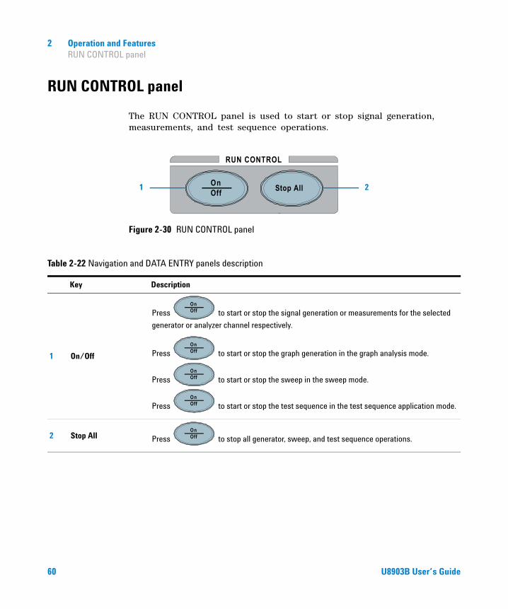
2 Operation and Features RUN CONTROL panel
RUN CONTROL panel
The RUN CONTROL panel is used to start or stop signal generation, measurements, and test sequence operations.
Figure 2-30 RUN CONTROL panel
RUN CONTROL
OnOff Stop All1 2
Table 2-22 Navigation and DATA ENTRY panels description
Key Description
1 On/Off
Press to start or stop the signal generation or measurements for the selected
generator or analyzer channel respectively.
Press to start or stop the graph generation in the graph analysis mode.
Press to start or stop the sweep in the sweep mode.
Press to start or stop the test sequence in the test sequence application mode.
2 Stop All Press to stop all generator, sweep, and test sequence operations.
OnOff
OnOff
OnOff
OnOff
OnOff
60 U8903B User’s Guide

Operation and Features 2 Save and Recall
Save and Recall
SaveThe Save menu page allows you to save the U8903B state, graph analysis trace settings, sweep function points, or screen capture of the current display into a file.
Figure 2-31 Save menu page
Table 2-23 Save menu description
Menu Description
Save Press the Save softkey to save the specific function to a file.
TypePress the Type softkey to select the file type to be displayed on the current directory and to be saved into.
Rename Press the Rename softkey to rename the selected file in the current directory.
Copy or Move Press the Copy or Move softkey to copy or move the marked files to the selected folder.
Delete Press the Delete softkey to delete the selected file in the current directory.
New Folder Press the New Folder softkey to create a new folder in the current directory.
U8903B User’s Guide 61

2 Operation and Features Save and Recall
Select the ‘...’ item at the list and press to move up a level from
the current folder or to another directory. Use the arrow keys to navigate
through the files or select the desired folder or file.
Recall
The Recall menu page allows you to recall the U8903B state, graph analysis trace settings, or sweep function points from a file.
Figure 2-32 Recall menu page
Enter
Table 2-24 Save menu description
Menu Description
Recall Press the Recall softkey to recall the selected file.
Type Press the Type softkey to select the file type to be displayed on the current directory.
Rename Press the Rename softkey to rename the selected file in the current directory.
Copy or Move Press the Copy or Move softkey to copy or move the marked files to the selected folder.
62 U8903B User’s Guide

Operation and Features 2 Save and Recall
Select the ‘...’ item at the list and press to move up a level from
the current folder or to another directory. Use the arrow keys to navigate
through the files or select the desired folder or file.
Delete Press the Delete softkey to delete the selected file in the current directory.
New Folder Press the New Folder softkey to create a new folder in the current directory.
Table 2-24 Save menu description (continued)
Menu Description
Enter
U8903B User’s Guide 63

2 Operation and Features Save and Recall
THIS PAGE HAS BEEN INTENTIONALLY LEFT BLANK.
64 U8903B User’s Guide
U8903B Audio AnalyzerUser’s Guide
3Audio Generator Functions
Audio Generator 66
Waveform Configuration 68Sine waveform 68Variable phase waveform 69Dual waveform 70SMPTE IMD waveforms (1:1/4:1/10:1) 71DFD IEC waveforms (IEC 60118/IEC 60268) 73Gaussian noise 75Rectangular noise 76Pink noise 77Square waveform 78DC signal 79Multitone waveform 82Arbitrary waveform 80Dual-Tone Multi-Frequency (DTMF) 86
Output Configuration 90
References 92
This chapter describes the U8903B audio generator functions and configurations.
65Agilent Technologies

3 Audio Generator Functions Audio Generator
Audio Generator
Press on the FUNCTION panel to switch between audio generator or audio analyzer mode. The Analog Generator menu page is displayed as shown in Figure 3- 1.
Press or on the DATA ENTRY panel to switch to channel 1 or channel 2 respectively and start configuring the active channel.
Press on the RUN CONTROL panel to start or stop the signal generation for the selected generator channel.
Figure 3-1 Analog Generator menu page
GeneratorAnalyzer
1 2 ABC
OnOff
66 U8903B User’s Guide

Audio Generator Functions 3 Audio Generator
Table 3-1 Analog Generator menu description
Menu Description
WaveformPress the Waveform softkey to display the list of available analog generator waveform types. Select the desired waveform from the drop-down list.
Waveform ConfigPress the Waveform Config softkey to set the current active waveform configuration such as frequency, amplitude, and others. Refer to “Waveform Configuration” on page 68 for more information.
Output ConfigPress the Output Config softkey to set the output configurations such as the connector type, impedance, and others. Refer to “Output Configuration” on page 90 for more information.
ReferencesPress the References softkey to configure the output references settings that are used in the unit conversion. Refer to “References” on page 92 for more information.
U8903B User’s Guide 67
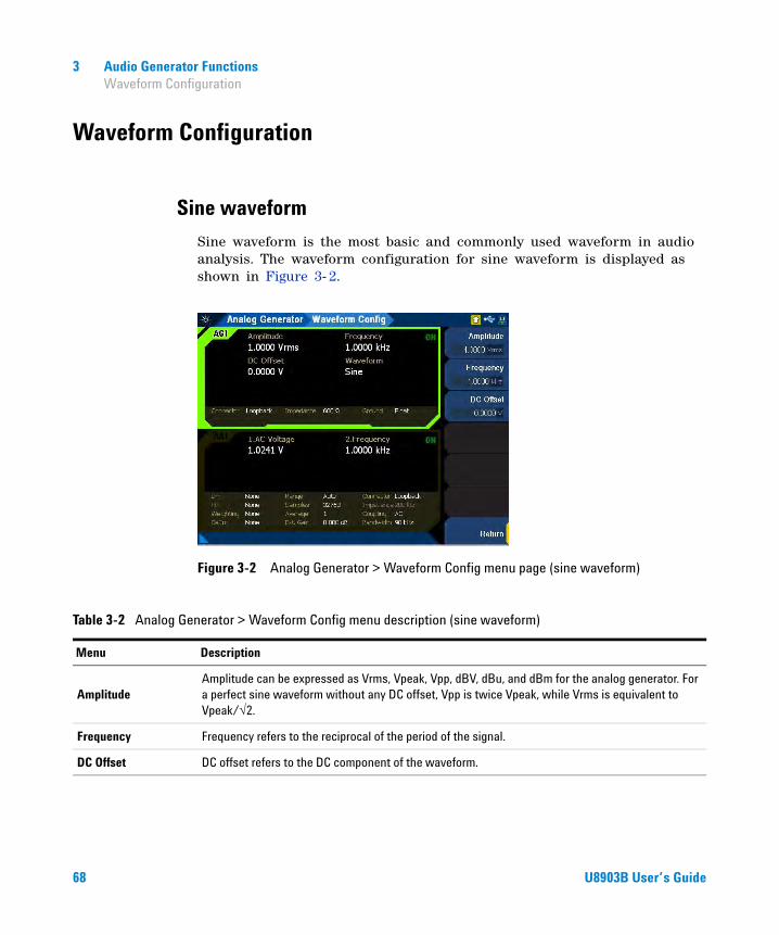
3 Audio Generator Functions Waveform Configuration
Waveform Configuration
Sine waveform
Sine waveform is the most basic and commonly used waveform in audio analysis. The waveform configuration for sine waveform is displayed as shown in Figure 3- 2.
Figure 3-2 Analog Generator > Waveform Config menu page (sine waveform)
Table 3-2 Analog Generator > Waveform Config menu description (sine waveform)
Menu Description
AmplitudeAmplitude can be expressed as Vrms, Vpeak, Vpp, dBV, dBu, and dBm for the analog generator. For a perfect sine waveform without any DC offset, Vpp is twice Vpeak, while Vrms is equivalent to Vpeak/√2.
Frequency Frequency refers to the reciprocal of the period of the signal.
DC Offset DC offset refers to the DC component of the waveform.
68 U8903B User’s Guide

Audio Generator Functions 3 Waveform Configuration
Variable phase waveform
Variable phase waveform outputs a sine waveform on all channels. The waveforms on all channels share the same frequency; however their phase and amplitude can differ. Variable phase waveforms are useful for measuring the phase difference or timing skew between the channels of a multiple channel audio system. Variable phase waveform outputs a sine waveform at the selected frequency at both channel outputs with the channel 2 output phase varies from –180° to +179.99°, relative to the channel 1 output. The waveform configuration for variable phase waveform is displayed as shown in Figure 3- 3.
Figure 3-3 Analog Generator > Waveform Config menu page (variable phase waveform)
Table 3-3 Analog Generator > Waveform Config menu description (variable phase waveform)
Menu Description
AmplitudeAmplitude can be expressed as Vrms, Vpeak, Vpp, dBV, dBu, and dBm for analog generator. For a perfect sine waveform without any DC offset, Vpp is twice Vpeak, while Vrms is equivalent to Vpeak/√2.
Frequency Frequency refers to the reciprocal of the period of the signal.
Phase -> 1
Phase -> 1 refers to the phase of the channel 2 sine waveform with reference to channel 1. A positive value will cause the channel 1 output to lead the channel 2 output. A negative value will cause the channel 2 output to lag the channel 1 output.
This is only available when the analog generator is in channel 2.
U8903B User’s Guide 69

3 Audio Generator Functions Waveform Configuration
Dual waveform
Dual waveform allows you to generate a composite waveform that is the summation of two independent sine waveforms. Dual sine waveforms are useful in testing the intermodulation distortion characteristics of an audio system. The waveform configuration for dual waveform is displayed as shown in Figure 3- 4.
Figure 3-4 Analog Generator > Waveform Config menu page (dual waveform)
Table 3-4 Analog Generator > Waveform Config menu description (variable phase waveform)
Menu Description
Amplitude Amplitude refers to the amplitude of the composite signal.
Frequency Frequency refers to the frequency for the first sine component.
Frequency 2 Frequency 2 refers to the frequency for the second sine component.
DC Offset DC offset refers to the DC component of the waveform.
Ratio Ratio refers to the amplitude ratio of the second sine component over the first sine component.
70 U8903B User’s Guide

Audio Generator Functions 3 Waveform Configuration
SMPTE IMD waveforms (1:1/4:1/10:1)
SMPTE IMD is a signal which is the linear combination of two sine waveforms. The SMPTE IMD waveforms conform to the SMPTE standard RP120- 1983 for testing intermodulation distortion. For SMPTE IMD 1:1, the lower frequency sine wave is linearly combined in 1:1 amplitude ratio with the upper frequency sine wave. For SMPTE IMD 4:1, the lower frequency sine wave is linearly combined in 4:1 amplitude ratio with the upper frequency sine wave. For SMPTE IMD 10:1, the lower frequency sine wave is linearly combined in 10:1 amplitude ratio with the upper frequency sine wave. The waveform configuration for SMPTE 1:1 waveform is displayed as shown in Figure 3- 5.
Figure 3-5 Analog Generator > Waveform Config menu page (SMPTE 1:1 waveform)
U8903B User’s Guide 71

3 Audio Generator Functions Waveform Configuration
Table 3-5 Analog Generator > Waveform Config menu description (SMPTE IMD waveforms)
Menu Description
Amplitude Amplitude refers to the amplitude of the composite signal.
Lower FreqLower Freq refers to the lower frequency of the waveform. The lower and upper frequencies are differentiated by the amplitude ratio between the frequencies.
Upper FreqUpper Freq refers to the upper frequency of the waveform. The lower and upper frequencies are differentiated by the amplitude ratio between the frequencies.
DC Offset DC offset refers to the DC component of the waveform.
72 U8903B User’s Guide
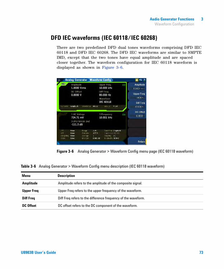
Audio Generator Functions 3 Waveform Configuration
DFD IEC waveforms (IEC 60118/IEC 60268)
There are two predefined DFD dual tones waveforms comprising DFD IEC 60118 and DFD IEC 60268. The DFD IEC waveforms are similar to SMPTE IMD, except that the two tones have equal amplitude and are spaced closer together. The waveform configuration for IEC 60118 waveform is displayed as shown in Figure 3- 6.
Figure 3-6 Analog Generator > Waveform Config menu page (IEC 60118 waveform)
Table 3-6 Analog Generator > Waveform Config menu description (IEC 60118 waveform)
Menu Description
Amplitude Amplitude refers to the amplitude of the composite signal.
Upper Freq Upper Freq refers to the upper frequency of the waveform.
Diff Freq Diff Freq refers to the difference frequency of the waveform.
DC Offset DC offset refers to the DC component of the waveform.
U8903B User’s Guide 73
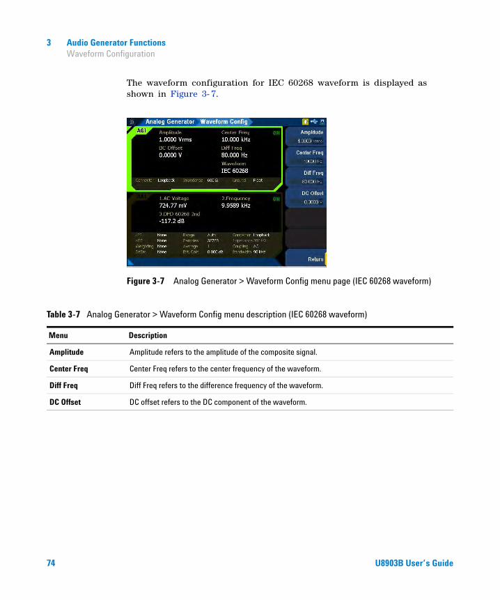
3 Audio Generator Functions Waveform Configuration
The waveform configuration for IEC 60268 waveform is displayed as shown in Figure 3- 7.
Figure 3-7 Analog Generator > Waveform Config menu page (IEC 60268 waveform)
Table 3-7 Analog Generator > Waveform Config menu description (IEC 60268 waveform)
Menu Description
Amplitude Amplitude refers to the amplitude of the composite signal.
Center Freq Center Freq refers to the center frequency of the waveform.
Diff Freq Diff Freq refers to the difference frequency of the waveform.
DC Offset DC offset refers to the DC component of the waveform.
74 U8903B User’s Guide

Audio Generator Functions 3 Waveform Configuration
Gaussian noise
Gaussian noise is a random noise signal where the frequency components have a Gaussian distribution centered on a predetermined frequency value. The waveform configuration for Gaussian noise is displayed as shown in Figure 3- 8.
Figure 3-8 Analog Generator > Waveform Config menu page (Gaussian noise)
Table 3-8 Analog Generator > Waveform Config menu description (Gaussian noise)
Menu Description
Amplitude Amplitude refers to the amplitude of the composite signal.
DC Offset DC offset refers to the DC component of the waveform.
U8903B User’s Guide 75

3 Audio Generator Functions Waveform Configuration
Rectangular noise
Rectangular noise is a noise signal based on Rectangular distribution. The waveform configuration for Rectangular noise is displayed as shown in Figure 3- 9.
Figure 3-9 Analog Generator > Waveform Config menu page (Rectangular noise)
Table 3-9 Analog Generator > Waveform Config menu description (Rectangular noise)
Menu Description
Amplitude Amplitude refers to the amplitude of the composite signal.
DC Offset DC offset refers to the DC component of the waveform.
76 U8903B User’s Guide

Audio Generator Functions 3 Waveform Configuration
Pink noise
Pink noise is a noise signal that contains an equal sound pressure level in each octave band where the energy decreases as frequency increases. The waveform configuration for pink noise is displayed as shown in Figure 3- 10.
Figure 3-10 Analog Generator > Waveform Config menu page (Pink noise)
Table 3-10 Analog Generator > Waveform Config menu description (Pink noise)
Menu Description
Amplitude Amplitude refers to the amplitude of the composite signal.
DC Offset DC offset refers to the DC component of the waveform.
U8903B User’s Guide 77

3 Audio Generator Functions Waveform Configuration
Square waveform
Square waveform is a waveform that ideally alternates regularly and instantaneously between two levels. The waveform configuration for square waveform is displayed as shown in Figure 3- 11.
Figure 3-11 Analog Generator > Waveform Config menu page (square waveform)
Table 3-11 Analog Generator > Waveform Config menu description (square waveform)
Menu Description
Amplitude Amplitude refers to the amplitude of the composite signal.
Frequency Frequency refers to the frequency of the square waveform.
78 U8903B User’s Guide

Audio Generator Functions 3 Waveform Configuration
DC signal
DC signal output is used when a low current DC supply is required. For example, biasing amplifiers or other similar circuitry. The waveform configuration for DC signal is displayed as shown in Figure 3- 12.
Figure 3-12 Analog Generator > Waveform Config menu page (DC signal)
Table 3-12 Analog Generator > Waveform Config menu description (DC signal)
Menu Description
Voltage Voltage refers to the amplitude of the composite signal.
U8903B User’s Guide 79

3 Audio Generator Functions Waveform Configuration
Arbitrary waveform
You can load a properly formatted waveform file into the U8903B as a sequence of waveform samples, with a maximum length of 32768 points. The samples are outputted at a fixed sampling rate of 192 kHz from the generator, in a continuous sequence. The waveform files must be in the .arb or .wav file type. For .wav file type, mono or stereo audio with 8, 16, or 24 bits per sample are supported. The waveform configuration for arbitrary waveform is displayed as shown in Figure 3- 13. Refer to “Appendix M: Arbitrary File Format” on page 435 for more information on the arbitrary waveform file format.
Figure 3-13 Analog Generator > Waveform Config menu page (arbitrary waveform)
80 U8903B User’s Guide
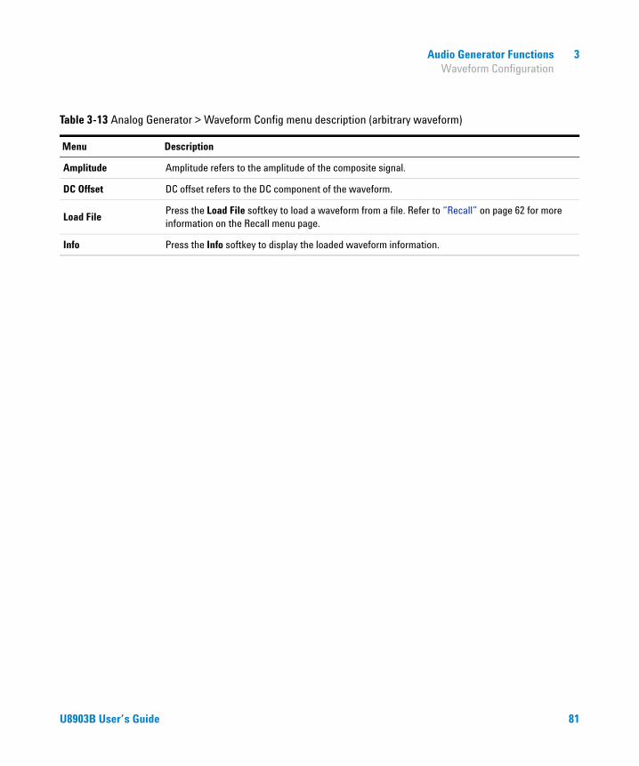
Audio Generator Functions 3 Waveform Configuration
Table 3-13 Analog Generator > Waveform Config menu description (arbitrary waveform)
Menu Description
Amplitude Amplitude refers to the amplitude of the composite signal.
DC Offset DC offset refers to the DC component of the waveform.
Load FilePress the Load File softkey to load a waveform from a file. Refer to “Recall” on page 62 for more information on the Recall menu page.
Info Press the Info softkey to display the loaded waveform information.
U8903B User’s Guide 81
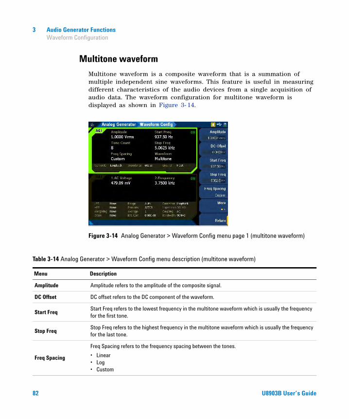
3 Audio Generator Functions Waveform Configuration
Multitone waveform
Multitone waveform is a composite waveform that is a summation of multiple independent sine waveforms. This feature is useful in measuring different characteristics of the audio devices from a single acquisition of audio data. The waveform configuration for multitone waveform is displayed as shown in Figure 3- 14.
Figure 3-14 Analog Generator > Waveform Config menu page 1 (multitone waveform)
Table 3-14 Analog Generator > Waveform Config menu description (multitone waveform)
Menu Description
Amplitude Amplitude refers to the amplitude of the composite signal.
DC Offset DC offset refers to the DC component of the waveform.
Start FreqStart Freq refers to the lowest frequency in the multitone waveform which is usually the frequency for the first tone.
Stop FreqStop Freq refers to the highest frequency in the multitone waveform which is usually the frequency for the last tone.
Freq Spacing
Freq Spacing refers to the frequency spacing between the tones.
• Linear• Log• Custom
82 U8903B User’s Guide

Audio Generator Functions 3 Waveform Configuration
Tone CountTones refer to the number of signal frequency components. The maximum number of tones that can be generated is 60.
Length
Length refers to the waveform length that determines the number of samples used to create one iteration of the multitone waveform. Longer waveform length provides higher frequency resolution but will take more time to generate and process.
• 1024• 2048• 4096• 8192• 16384• 32768• 65536
CustomPress the Custom softkey to access the custom multitone menu page. You can set the frequency, amplitude, phase, and optimize the crest factor for each tone. Refer to “Custom multitone” on page 84 for more information on the custom multitone menu page.
Table 3-14 Analog Generator > Waveform Config menu description (multitone waveform)
Menu Description
U8903B User’s Guide 83

3 Audio Generator Functions Waveform Configuration
Custom multitone
The custom multitone waveform configuration is displayed as shown in Figure 3- 15.
Figure 3-15 Analog Generator > Waveform Config > Custom menu page 1 (multitone waveform)
Table 3-15 Analog Generator > Waveform Config > Custom menu description (multitone waveform)
Menu Description
ApplyPress the Apply softkey to apply the current setting on the selected tone for the custom multitone waveform.
Optimize Press the Optimize softkey to optimize the crest factor for the custom multitone waveform.
Frequency Press the Frequency softkey to set the frequency value for the custom multitone waveform.
Amplitude Press the Amplitude softkey to set the amplitude value for the custom multitone waveform.
Phase Press the Phase softkey to set the phase value for the custom multitone waveform.
Add AbovePress the Add Above softkey to add the tone above the selected tone for the custom multitone waveform.
Add BelowPress the Add Below softkey to add the tone below the selected tone for the custom multitone waveform.
84 U8903B User’s Guide
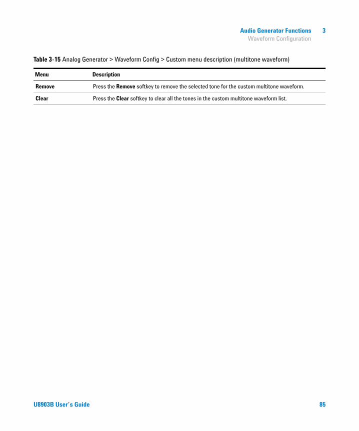
Audio Generator Functions 3 Waveform Configuration
Remove Press the Remove softkey to remove the selected tone for the custom multitone waveform.
Clear Press the Clear softkey to clear all the tones in the custom multitone waveform list.
Table 3-15 Analog Generator > Waveform Config > Custom menu description (multitone waveform)
Menu Description
U8903B User’s Guide 85

3 Audio Generator Functions Waveform Configuration
Dual-Tone Multi-Frequency (DTMF)
Dual- Tone Multi- Frequency (DTMF), also known as touch- tone, is a system of signal tones used in telecommunications. Applications include voice mail, help desks, telephone banking, and others.
There are 12 DTMF signals where each of the signal is made up of two tones from the following selection:
• 697 Hz
• 770 Hz
• 852 Hz
• 941 Hz
• 1209 Hz
• 1336 Hz
• 1477Hz
The tones are divided into two groups (low and high), and each DTMF signal uses one from each group. This prevents any harmonics from being misinterpreted as part of the signal. The waveform configuration for DTMF is displayed as shown in Figure 3- 16.
Figure 3-16 Analog Generator > Waveform Config menu page 1 (DTMF)
86 U8903B User’s Guide
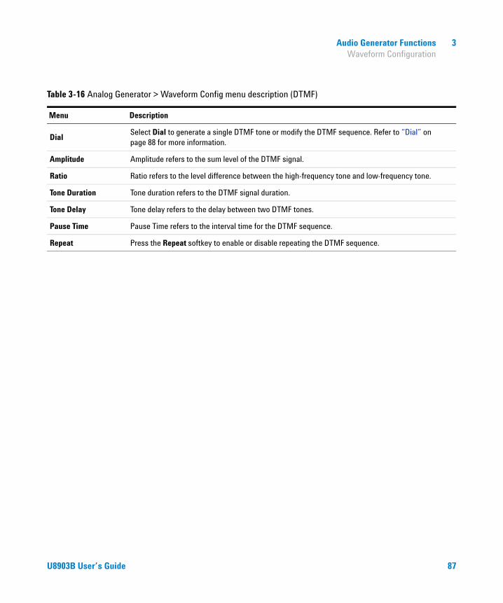
Audio Generator Functions 3 Waveform Configuration
Table 3-16 Analog Generator > Waveform Config menu description (DTMF)
Menu Description
DialSelect Dial to generate a single DTMF tone or modify the DTMF sequence. Refer to “Dial” on page 88 for more information.
Amplitude Amplitude refers to the sum level of the DTMF signal.
Ratio Ratio refers to the level difference between the high-frequency tone and low-frequency tone.
Tone Duration Tone duration refers to the DTMF signal duration.
Tone Delay Tone delay refers to the delay between two DTMF tones.
Pause Time Pause Time refers to the interval time for the DTMF sequence.
Repeat Press the Repeat softkey to enable or disable repeating the DTMF sequence.
U8903B User’s Guide 87
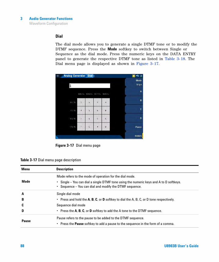
3 Audio Generator Functions Waveform Configuration
Dial
The dial mode allows you to generate a single DTMF tone or to modify the DTMF sequence. Press the Mode softkey to switch between Single or Sequence as the dial mode. Press the numeric keys on the DATA ENTRY panel to generate the respective DTMF tone as listed in Table 3- 18. The Dial menu page is displayed as shown in Figure 3- 17.
Figure 3-17 Dial menu page
Table 3-17 Dial menu page description
Menu Description
ModeMode refers to the mode of operation for the dial mode.
• Single – You can dial a single DTMF tone using the numeric keys and A to D softkeys.• Sequence – You can dial and modify the DTMF sequence.
A
B
C
D
Single dial mode
• Press and hold the A, B, C, or D softkey to dial the A, B, C, or D tone respectively.
Sequence dial mode
• Press the A, B, C, or D softkey to add the A tone to the DTMF sequence.
PausePause refers to the pause to be added to the DTMF sequence.
• Press the Pause softkey to add a pause to the sequence in the form of a comma.
88 U8903B User’s Guide
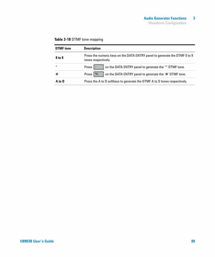
Audio Generator Functions 3 Waveform Configuration
Table 3-18 DTMF tone mapping
DTMF tone Description
0 to 9Press the numeric keys on the DATA ENTRY panel to generate the DTMF 0 to 9 tones respectively.
* Press on the DATA ENTRY panel to generate the ‘*’ DTMF tone.
# Press on the DATA ENTRY panel to generate the ‘#’ DTMF tone.
A to D Press the A to D softkeys to generate the DTMF A to D tones respectively.
U8903B User’s Guide 89

3 Audio Generator Functions Output Configuration
Output Configuration
The output configuration for the analog generator is displayed as shown in Figure 3- 18.
Figure 3-18 Analog Generator > Output Config menu page
Table 3-19 Analog Generator > Output Config menu description
Menu Description
Connector
Press the Connector softkey to select the output connector type.
• Bal Balanced mode outputs a pair of differential signals which are equal in amplitude but 180 degrees out of phase on the XLR positive and negative pins.
• UnBal Unbalanced mode outputs a signal referenced to ground on the BNC output connector.
• Com Common mode outputs a pair of equal amplitude and in-phase signals on the XLR positive and negative pins. The common mode test signal is applied to both pins 2 and 3 or the XLR connector, while pin 1 is connected to the return signal.
• IEC60268 The common mode test signal is applied to both pins 2 and 3 or the XLR connector, while pin 1 is connected to the return signal. An additional 10 Ω output series resistance is added to pin 2 or 3.
90 U8903B User’s Guide

Audio Generator Functions 3 Output Configuration
Impedance
Press the Impedance softkey to select the output impedance value.
For Bal, Com, and IEC60268
• 600 Ω• 100 Ω• 40 ΩFor UnBal
• 600 Ω• 50 Ω• 20 Ω
IEC60268 10 Ω
Press the IEC60268 10 Ω softkey to select the additional 10 Ω output series resistance for pin 2 or 3 of the XLR connector in the common IEC60268 configuration. This setting is only available when the output connector type is set to IEC60268.
• Pin2 Additional 10 Ω is added to pin 2.
• Pin3 Additional 10 Ω is added to pin 3.
Ground
Press the Ground softkey to select the grounding type.
• Float In the floating grounding type, the signal return line (XLR pin 1 for balanced output or BNC return for unbalanced output) is not grounded to the chassis earth and is “floating”.
• Ground In the ground grounding type, the signal return line (XLR pin 1 for balanced output or BNC return for unbalanced output) is connected to the chassis earth.
Max VoltagePress the Max Voltage softkey to set the maximum voltage. The maximum voltage value set will limit the maximum amplitude output from the generator and prevent any excessive high voltage values from damaging the device under test (DUT).
Table 3-19 Analog Generator > Output Config menu description (continued)
Menu Description
U8903B User’s Guide 91

3 Audio Generator Functions References
References
The output references for analog generator is displayed as shown in Figure 3- 19.
Figure 3-19 Analog Generator > References menu page
Table 3-20 Analog Generator > References menu description
Menu Description
Ref. ImpPress the Ref. Imp softkey to set the reference impedance for the unit conversion of dBm measurements.
92 U8903B User’s Guide

U8903B Audio AnalyzerUser’s Guide
4Audio Analyzer Measurement Functions
Audio Analyzer 94
Functions 96
Measurement Functions 97Frequency measurement 97AC voltage level measurement 99DC voltage level measurement 102THD+N ratio and THD+N level measurements 104SINAD measurement 109THD ratio and THD level measurements 111SMPTE IMD measurements 117DFD measurements 119SNR measurement 121SNR (fast mode) measurement 123
Phase measurement 125
Crosstalk measurement 127
Filters Configuration 129Notch Filter 132
Measurement Configuration 133
Input Configuration 135
Wave File 137
Statistics 139
This chapter describes the U8903B audio analyzer measurement functions and configurations.
93Agilent Technologies

4 Audio Analyzer Measurement Functions Audio Analyzer
Audio Analyzer
Press on the FUNCTION panel to switch between audio generator or audio analyzer mode. The Analog Analyzer menu page is displayed as shown in Figure 4- 1.
Press or on the DATA ENTRY panel to switch to channel 1 or channel 2 respectively and start configuring the active channel.
The U8903B can also be expanded with additional analog analyzer channels. Refer to “U8903B Options” on page 5 for more information.
Press on the RUN CONTROL panel to start or stop the measurements for the selected analyzer channel.
Figure 4-1 Analog Analyzer menu page
GeneratorAnalyzer
1 2 ABC
OnOff
94 U8903B User’s Guide
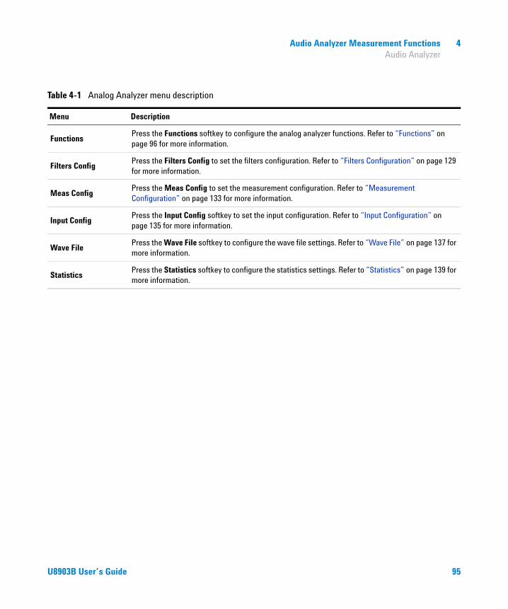
Audio Analyzer Measurement Functions 4 Audio Analyzer
Table 4-1 Analog Analyzer menu description
Menu Description
FunctionsPress the Functions softkey to configure the analog analyzer functions. Refer to “Functions” on page 96 for more information.
Filters ConfigPress the Filters Config to set the filters configuration. Refer to “Filters Configuration” on page 129 for more information.
Meas ConfigPress the Meas Config to set the measurement configuration. Refer to “Measurement Configuration” on page 133 for more information.
Input ConfigPress the Input Config softkey to set the input configuration. Refer to “Input Configuration” on page 135 for more information.
Wave FilePress the Wave File softkey to configure the wave file settings. Refer to “Wave File” on page 137 for more information.
StatisticsPress the Statistics softkey to configure the statistics settings. Refer to “Statistics” on page 139 for more information.
U8903B User’s Guide 95

4 Audio Analyzer Measurement Functions Functions
Functions
The U8903B supports up to four functions to be measured in one single query. The function configuration for analog analyzer is displayed as shown in Figure 4- 2.
Figure 4-2 Analog Analyzer > Functions menu page
Table 4-2 Analog Analyzer > Functions menu description
Menu Description
Multi-Chn
Press the Multi-Chn softkey to select the multichannel measurement mode.
• Off The measurement functions are set independently across all channels.
• Phase Refer to “Phase measurement” on page 125 for the configuration.
• X-Talk Refer to “Crosstalk measurement” on page 127 for the configuration.
Function No. Press the Function No. softkey to select the active function number to configure the settings.
Meas. Func.
Press the Meas. Func. softkey to display the list of available analog analyzer measurement function types. Select the desired measurement function from the drop-down list. Refer to “Measurement Functions” on page 97 for the respective measurement functions settings.
This setting is only available when the multichannel mode is set to Off.
96 U8903B User’s Guide

Audio Analyzer Measurement Functions 4 Measurement Functions
Measurement Functions
Frequency measurement
Frequency is a common and basic measurement function which is expressed in hertz (Hz). The U8903B uses software algorithm to detect the period of a repetitive waveform and the frequency is computed from the reciprocal of the period.
To obtain better accuracy and resolution, autoranging should be enabled. For low- frequency signals, set a larger sample size to obtain better and more stable readings. Input filters can also be activated to remove unwanted high- frequency noise from the measured signal, allowing more stable readings.
The settings for frequency measurement are displayed as shown in Figure 4- 3.
Figure 4-3 Analog Analyzer > Functions > Frequency menu page 1
U8903B User’s Guide 97

4 Audio Analyzer Measurement Functions Measurement Functions
Table 4-3 Analog Analyzer > Functions > Frequency menu description
Menu Description
UnitPress the Unit softkey to select the measurement unit.
• Hz• ΔHz
Format
Press the Format softkey to select the format of the returned measurement reading.
• Off Selecting Off will return the measurement reading without any formating (raw value).
• Delta Selecting Delta will return the measurement result by deducting the reference frequency from the measured frequency.
Set result as ref. fromPress the Set result as ref. from softkey to store the measurement result from the selected channel as the reference frequency.
Ref. Freq Press the Ref. Freq softkey to set the reference frequency.
98 U8903B User’s Guide
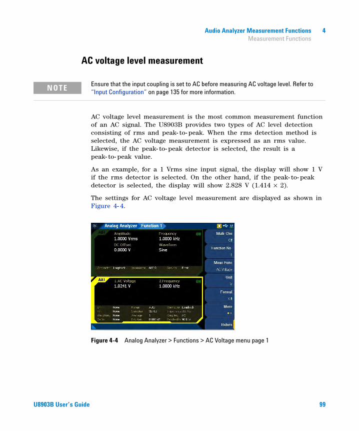
Audio Analyzer Measurement Functions 4 Measurement Functions
AC voltage level measurement
AC voltage level measurement is the most common measurement function of an AC signal. The U8903B provides two types of AC level detection consisting of rms and peak- to- peak. When the rms detection method is selected, the AC voltage measurement is expressed as an rms value. Likewise, if the peak- to- peak detector is selected, the result is a peak- to- peak value.
As an example, for a 1 Vrms sine input signal, the display will show 1 V if the rms detector is selected. On the other hand, if the peak- to- peak detector is selected, the display will show 2.828 V (1.414 × 2).
The settings for AC voltage level measurement are displayed as shown in Figure 4- 4.
Figure 4-4 Analog Analyzer > Functions > AC Voltage menu page 1
NOTE Ensure that the input coupling is set to AC before measuring AC voltage level. Refer to “Input Configuration” on page 135 for more information.
U8903B User’s Guide 99
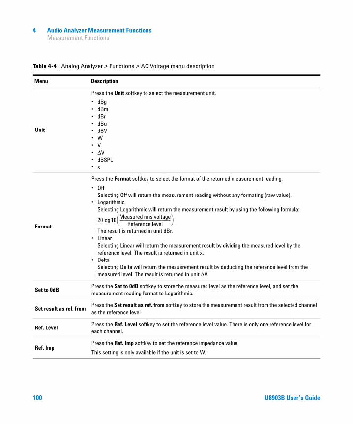
4 Audio Analyzer Measurement Functions Measurement Functions
Table 4-4 Analog Analyzer > Functions > AC Voltage menu description
Menu Description
Unit
Press the Unit softkey to select the measurement unit.
• dBg• dBm• dBr• dBu• dBV• W• V• ΔV• dBSPL• x
Format
Press the Format softkey to select the format of the returned measurement reading.
• Off Selecting Off will return the measurement reading without any formating (raw value).
• Logarithmic Selecting Logarithmic will return the measurement result by using the following formula:
The result is returned in unit dBr.
• Linear Selecting Linear will return the measurement result by dividing the measured level by the reference level. The result is returned in unit x.
• Delta Selecting Delta will return the meausrement result by deducting the reference level from the measured level. The result is returned in unit ΔV.
Set to 0dBPress the Set to 0dB softkey to store the measured level as the reference level, and set the measurement reading format to Logarithmic.
Set result as ref. fromPress the Set result as ref. from softkey to store the measurement result from the selected channel as the reference level.
Ref. LevelPress the Ref. Level softkey to set the reference level value. There is only one reference level for each channel.
Ref. ImpPress the Ref. Imp softkey to set the reference impedance value.
This setting is only available if the unit is set to W.
20 10Measured rms voltage
Reference level-----------------------------------------------------------⎝ ⎠⎛ ⎞log
100 U8903B User’s Guide

Audio Analyzer Measurement Functions 4 Measurement Functions
Cal SPLPress the Cal SPL softkey to set the calibration level value.
This setting is only available when the unit is set to dBSPL.
DetectorPress the Detector softkey to select the AC level detection type.
• RMS• Pk-Pk
Table 4-4 Analog Analyzer > Functions > AC Voltage menu description (continued)
Menu Description
U8903B User’s Guide 101

4 Audio Analyzer Measurement Functions Measurement Functions
DC voltage level measurement
DC voltage levels are often encountered in audio equipment although they are not part of the audio signal. For example, bias voltages and outputs from AC- to- DC converters. DC voltage is expressed in volts (V). The input coupling must be set to DC for DC voltage level measurement. The settings for DC voltage level measurement are displayed as shown in Figure 4- 5.
Figure 4-5 Analog Analyzer > Functions > DC Voltage menu page 1
NOTE Ensure that the input coupling is set to DC before measuring DC voltage level. Refer to “Input Configuration” on page 135 for more information.
Table 4-5 Analog Analyzer > Functions > DC Voltage menu description
Menu Description
Unit
Press the Unit softkey to select the measurement unit.
• V• ΔV• x
102 U8903B User’s Guide

Audio Analyzer Measurement Functions 4 Measurement Functions
Format
Press the Format softkey to select the format of the returned measurement reading.
• Off Selecting Off will return the measurement reading without any formating (raw value).
• Linear Selecting Linear will return the measurement result by dividing the measured level by the reference level. The result is returned in unit x.
• Delta Selecting Delta will return the meausrement result by deducting the reference level from the measured level. The result is returned in unit ΔV.
Set result as ref. fromPress the Set result as ref. from softkey to store the measurement result from the selected channel as the reference level.
Ref. LevelPress the Ref. Level softkey to set the reference level value. There is only one reference level for each channel.
Table 4-5 Analog Analyzer > Functions > DC Voltage menu description (continued)
Menu Description
U8903B User’s Guide 103

4 Audio Analyzer Measurement Functions Measurement Functions
THD+N ratio and THD+N level measurements
Harmonic distortion on a spectrally pure signal is created by nonlinearities in the circuit through which it passes. The nonlinearities can arise in the transfer characteristics of an active device or by running the active device into saturation or cutoff. In most cases, distortion can be reduced by decreasing the signal level, applying filtering, or adding negative feedback.
According to Fourier mathematics, the nonlinear terms in the circuit transfer function give rise to harmonics of the signal. Therefore, the THD+N function provides a quantitative measurement of the quality of an audio signal or in other words, the purity of a signal.
The THD+N ratio is defined as the ratio of the square root of the sum of the squares of all the signal harmonics components and noise amplitude, relative to the total signal amplitude. The THD+N ratio can be computed as follows.
The settings for THD+N ratio measurement are displayed as shown in Figure 4- 6.
Figure 4-6 Analog Analyzer > Functions > THD+N Ratio menu page 1
THD+N ratio 20 Log10rms value of noise and distortion
rms value of signal, noise, and distortion-----------------------------------------------------------------------------------------------------------⎝ ⎠⎛ ⎞=
104 U8903B User’s Guide

Audio Analyzer Measurement Functions 4 Measurement Functions
Table 4-6 Analog Analyzer > Functions > THD+N Ratio menu description
Menu Description
Unit
Press the Unit softkey to select the measurement unit.
• dB• ΔdB• %• x
Format
Press the Format softkey to select the format of the returned measurement reading.
• Off Selecting Off will return the measurement reading without any formating (raw value).
• Linear Selecting Linear will return the measurement result by dividing the measured ratio by the reference ratio. The result is returned in unit x.
• Delta Selecting Delta will return the measurement result by deducting the reference ratio from the measured ratio. The result will be returned in unit ΔdB.
Set to 0dBPress the Set to 0dB softkey to store the measured ratio as the reference ratio, and set the measurement reading format to Delta.
Set result as ref. fromPress the Set result as ref. from softkey to store the measurement result from the selected channel as the reference ratio.
Ref. Ratio Press the Ref. Ratio softkey to set the reference ratio value.
Freq Lock
Press the Freq Lock softkey to select the searching method for the fundamental frequency.
• Auto Selecting Auto will allow the U8903B to search for the fundamental frequency automatically.
• Gen Lock Selecting Gen Lock will allow the U8903B to search for the fundamental frequency based on the generator frequency value of the respective generator channel. You can select the generator channel by setting the Src Channel in the Meas. Config. menu page. This Gen Lock method is only useful if you use the internal audio generator.
• Custom If you have a known input signal, you can define the fundamental frequency value by setting the searching method to Custom and setting the frequency value in Fund Freq.
Fund FreqPress the Fund Freq softkey to set the fundamental frequency value. This setting is only available when Freq Lock is set to Custom.
U8903B User’s Guide 105

4 Audio Analyzer Measurement Functions Measurement Functions
THD+N level is defined as the square root of the sum of the squares of all the signal harmonics components and noise amplitude, and it is expressed in Vrms. The THD+N level can be computed as follows.
The settings for THD+N level measurement are displayed as shown in Figure 4- 7.
Figure 4-7 Analog Analyzer > Functions > THD+N Level menu page 1
THD+N Level rms value of noise and distortion=
Table 4-7 Analog Analyzer > Functions > THD+N Level menu description
Menu Description
Unit
Press the Unit softkey to select the measurement unit.
• dBg• dBm• dBr• dBu• dBV• W• V• ΔV• dBSPL• x
106 U8903B User’s Guide

Audio Analyzer Measurement Functions 4 Measurement Functions
Format
Press the Format softkey to select the format of the returned measurement reading.
• Off Selecting Off will return the measurement reading without any formating (raw value).
• Logarithmic Selecting Logarithmic will return the measurement result by using the following formula:
The result is returned in unit dBr.
• Linear Selecting Linear will return the measurement result by dividing the measured level by the reference level. The result is returned in unit x.
• Delta Selecting Delta will return the meausrement result by deducting the reference level from the measured level. The result is returned in unit ΔV.
Set to 0dBPress the Set to 0dB softkey to store the measured level as the reference level, and set the measurement reading format to Logarithmic.
Set result as ref. fromPress the Set result as ref. from softkey to store the measurement result from the selected channel as the reference level.
Ref. LevelPress the Ref. Level softkey to set the reference level value. There is only one reference level for each channel.
Ref. ImpPress the Ref. Imp softkey to set the reference impedance value.
This setting is only available if the unit is set to W.
Cal SPLPress the Cal SPL softkey to set the calibration level value.
This setting is only available when the unit is set to dBSPL.
Table 4-7 Analog Analyzer > Functions > THD+N Level menu description (continued)
Menu Description
20 10Measured rms voltage
Reference level-----------------------------------------------------------⎝ ⎠⎛ ⎞log
U8903B User’s Guide 107

4 Audio Analyzer Measurement Functions Measurement Functions
Freq Lock
Press the Freq Lock softkey to select the searching method for the fundamental frequency.
• Auto Selecting Auto will allow the U8903B to search for the fundamental frequency automatically.
• Gen Lock Selecting Gen Lock will allow the U8903B to search for the fundamental frequency based on the generator frequency value of the respective generator channel. You can select the generator channel by setting the Src Channel in the Meas. Config. menu page. This Gen Lock method is only useful if you use the internal audio generator.
• Custom If you have a known input signal, you can define the fundamental frequency value by setting the searching method to Custom and setting the frequency value in Fund Freq.
Fund FreqPress the Fund Freq softkey to set the fundamental frequency value. This setting is only available when Freq Lock is set to Custom.
Table 4-7 Analog Analyzer > Functions > THD+N Level menu description (continued)
Menu Description
108 U8903B User’s Guide
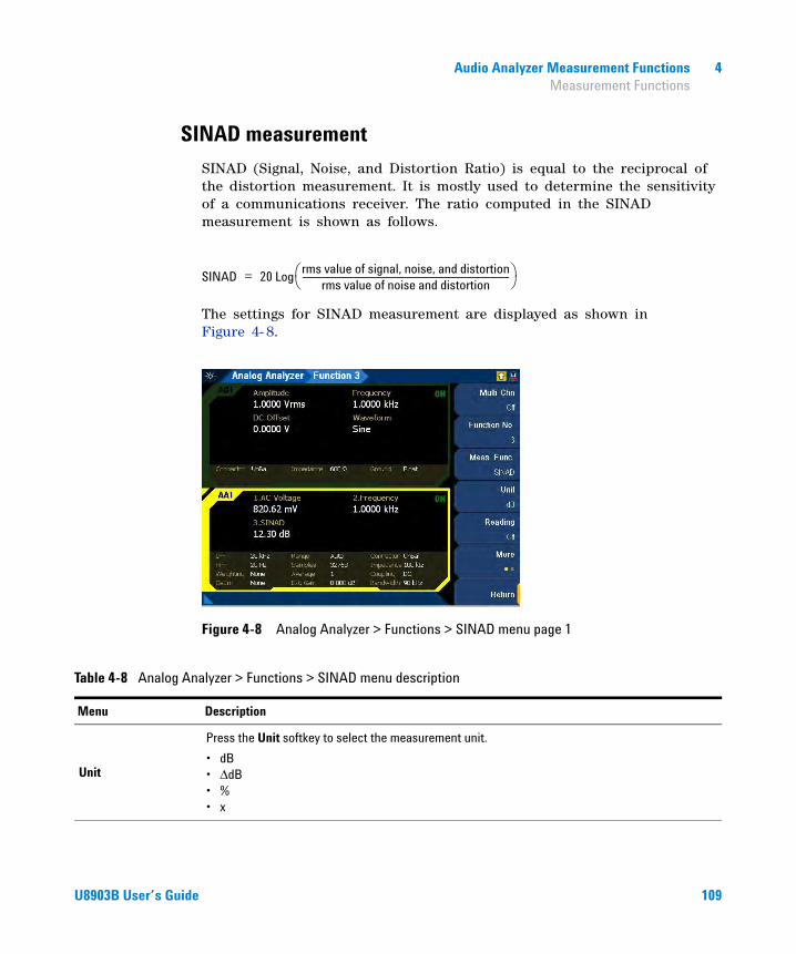
Audio Analyzer Measurement Functions 4 Measurement Functions
SINAD measurement
SINAD (Signal, Noise, and Distortion Ratio) is equal to the reciprocal of the distortion measurement. It is mostly used to determine the sensitivity of a communications receiver. The ratio computed in the SINAD measurement is shown as follows.
The settings for SINAD measurement are displayed as shown in Figure 4- 8.
Figure 4-8 Analog Analyzer > Functions > SINAD menu page 1
SINAD 20 Logrms value of signal, noise, and distortion
rms value of noise and distortion-----------------------------------------------------------------------------------------------------------⎝ ⎠⎛ ⎞=
Table 4-8 Analog Analyzer > Functions > SINAD menu description
Menu Description
Unit
Press the Unit softkey to select the measurement unit.
• dB• ΔdB• %• x
U8903B User’s Guide 109
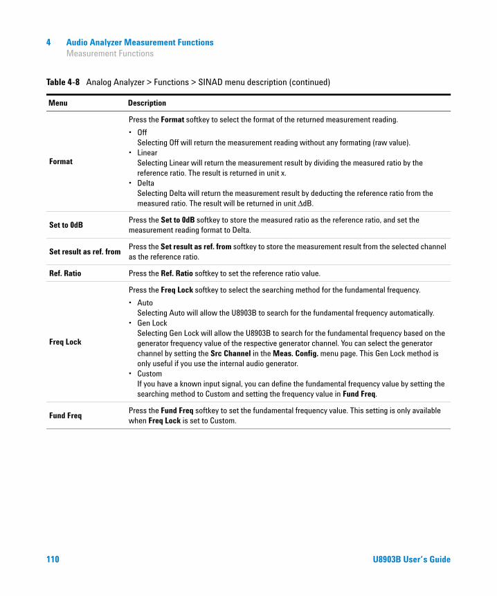
4 Audio Analyzer Measurement Functions Measurement Functions
Format
Press the Format softkey to select the format of the returned measurement reading.
• Off Selecting Off will return the measurement reading without any formating (raw value).
• Linear Selecting Linear will return the measurement result by dividing the measured ratio by the reference ratio. The result is returned in unit x.
• Delta Selecting Delta will return the measurement result by deducting the reference ratio from the measured ratio. The result will be returned in unit ΔdB.
Set to 0dBPress the Set to 0dB softkey to store the measured ratio as the reference ratio, and set the measurement reading format to Delta.
Set result as ref. fromPress the Set result as ref. from softkey to store the measurement result from the selected channel as the reference ratio.
Ref. Ratio Press the Ref. Ratio softkey to set the reference ratio value.
Freq Lock
Press the Freq Lock softkey to select the searching method for the fundamental frequency.
• Auto Selecting Auto will allow the U8903B to search for the fundamental frequency automatically.
• Gen Lock Selecting Gen Lock will allow the U8903B to search for the fundamental frequency based on the generator frequency value of the respective generator channel. You can select the generator channel by setting the Src Channel in the Meas. Config. menu page. This Gen Lock method is only useful if you use the internal audio generator.
• Custom If you have a known input signal, you can define the fundamental frequency value by setting the searching method to Custom and setting the frequency value in Fund Freq.
Fund FreqPress the Fund Freq softkey to set the fundamental frequency value. This setting is only available when Freq Lock is set to Custom.
Table 4-8 Analog Analyzer > Functions > SINAD menu description (continued)
Menu Description
110 U8903B User’s Guide
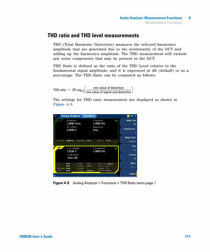
Audio Analyzer Measurement Functions 4 Measurement Functions
THD ratio and THD level measurements
THD (Total Harmonic Distortion) measures the selected harmonics amplitude that are generated due to the nonlinearity of the DUT and adding up the harmonics amplitude. The THD measurement will exclude any noise components that may be present in the DUT.
THD Ratio is defined as the ratio of the THD Level relative to the fundamental signal amplitude, and it is expressed in dB (default) or as a percentage. The THD Ratio can be computed as follows.
The settings for THD ratio measurement are displayed as shown in Figure 4- 9.
Figure 4-9 Analog Analyzer > Functions > THD Ratio menu page 1
THD ratio 20 Log10rms value of distortion
rms value of signal and distortion----------------------------------------------------------------------------------------⎝ ⎠⎛ ⎞=
U8903B User’s Guide 111

4 Audio Analyzer Measurement Functions Measurement Functions
Table 4-9 Analog Analyzer > Functions > THD Ratio menu description
Menu Description
Unit
Press the Unit softkey to select the measurement unit.
• dB• ΔdB• %• x
Format
Press the Format softkey to select the format of the returned measurement reading.
• Off Selecting Off will return the measurement reading without any formating (raw value).
• Delta Selecting Delta will return the measurement result by deducting the reference ratio from the measured ratio. The result will be returned in unit ΔdB.
• Linear Selecting Linear will return the measurement result by dividing the measured ratio by the reference ratio. The result is returned in unit x.
Set to 0dBPress the Set to 0dB softkey to store the measured ratio as the reference ratio, and set the measurement reading format to Delta.
Set result as ref. fromPress the Set result as ref. from softkey to store the measurement result from the selected channel as the reference ratio.
Ref. Ratio Press the Ref. Ratio softkey to set the reference ratio value.
Even Harmonic
Press the Even Harmonic softkey to display the even harmonics order selection. Press the Enter key on the navigation panel to select the desired even harmonics order, and press the Even Harmonic softkey again to confirm the selection.
• ALL• 2• 4• 6• 8
Odd Harmonic
Press the Odd Harmonic softkey to display the odd harmonics order selection. Press the Enter key on the navigation panel to select the desired odd harmonics order, and press the Odd Harmonic softkey again to confirm the selection.
• ALL• 3• 5• 7• 9
112 U8903B User’s Guide
Audio Analyzer Measurement Functions 4 Measurement Functions
Freq Lock
Press the Freq Lock softkey to select the searching method for the fundamental frequency.
• Auto Selecting Auto will allow the U8903B to search for the fundamental frequency automatically.
• Gen Lock Selecting Gen Lock will allow the U8903B to search for the fundamental frequency based on the generator frequency value of the respective generator channel. You can select the generator channel by setting the Src Channel in the Meas. Config. menu page. This Gen Lock method is only useful if you use the internal audio generator.
• Custom If you have a known input signal, you can define the fundamental frequency value by setting the searching method to Custom and setting the frequency value in Fund Freq.
Fund FreqPress the Fund Freq softkey to set the fundamental frequency value. This setting is only available when Freq Lock is set to Custom.
Table 4-9 Analog Analyzer > Functions > THD Ratio menu description (continued)
Menu Description
U8903B User’s Guide 113
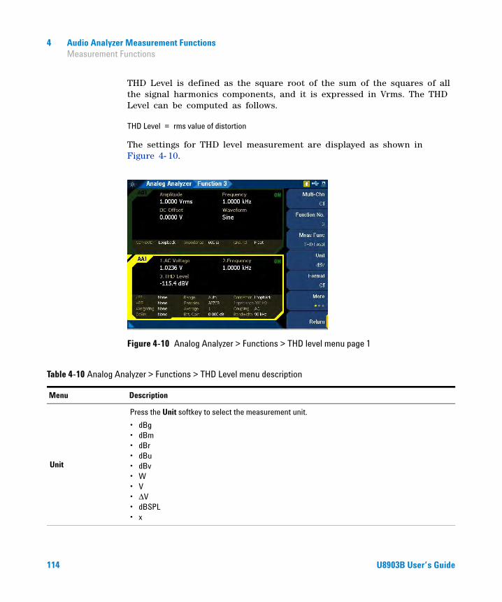
4 Audio Analyzer Measurement Functions Measurement Functions
THD Level is defined as the square root of the sum of the squares of all the signal harmonics components, and it is expressed in Vrms. The THD Level can be computed as follows.
The settings for THD level measurement are displayed as shown in Figure 4- 10.
Figure 4-10 Analog Analyzer > Functions > THD level menu page 1
THD Level rms value of distortion=
Table 4-10 Analog Analyzer > Functions > THD Level menu description
Menu Description
Unit
Press the Unit softkey to select the measurement unit.
• dBg• dBm• dBr• dBu• dBv• W• V• ΔV• dBSPL• x
114 U8903B User’s Guide

Audio Analyzer Measurement Functions 4 Measurement Functions
Format
Press the Format softkey to select the format of the returned measurement reading.
• Off Selecting Off will return the measurement reading without any formating (raw value).
• Logarithmic Selecting Logarithmic will return the measurement result by using the following formula:
The result is returned in unit dBr.
• Linear Selecting Linear will return the measurement result by dividing the measured level by the reference level. The result is returned in unit x.
• Delta Selecting Delta will return the meausrement result by deducting the reference level from the measured level. The result is returned in unit ΔV.
Set to 0dBPress the Set to 0dB softkey to store the measured level as the reference level, and set the measurement reading format to Logarithmic.
Set result as ref. fromPress the Set result as ref. from softkey to store the measurement result from the selected channel as the reference level.
Ref. LevelPress the Ref. Level softkey to set the reference level value. There is only one reference level for each channel.
Ref. ImpPress the Ref. Imp softkey to set the reference impedance value.
This setting is only available if the unit is set to W.
Cal SPLPress the Cal SPL softkey to set the calibration level value.
This setting is only available when the unit is set to dBSPL.
Even Harmonic
Press the Even Harmonic softkey to select the even harmonics.
• ALL• 2• 4• 6• 8
Table 4-10 Analog Analyzer > Functions > THD Level menu description (continued)
Menu Description
20 10Measured rms voltage
Reference level-----------------------------------------------------------⎝ ⎠⎛ ⎞log
U8903B User’s Guide 115
4 Audio Analyzer Measurement Functions Measurement Functions
Odd Harmonic
Press the Odd Harmonic softkey to select the odd harmonics.
• ALL• 3• 5• 7• 9
Freq Lock
Press the Freq Lock softkey to select the searching method for the fundamental frequency.
• Auto Selecting Auto will allow the U8903B to search for the fundamental frequency automatically.
• Gen Lock Selecting Gen Lock will allow the U8903B to search for the fundamental frequency based on the generator frequency value of the respective generator channel. You can select the generator channel by setting the Src Channel in the Meas. Config. menu page. This Gen Lock method is only useful if you use the internal audio generator.
• Custom If you have a known input signal, you can define the fundamental frequency value by setting the searching method to Custom and setting the frequency value in Fund Freq.
Fund FreqPress the Fund Freq softkey to set the fundamental frequency value. This setting is only available when Freq Lock is set to Custom.
Table 4-10 Analog Analyzer > Functions > THD Level menu description (continued)
Menu Description
116 U8903B User’s Guide
Audio Analyzer Measurement Functions 4 Measurement Functions
SMPTE IMD measurements
The SMPTE IMD function provides a measure of the second and third order intermodulation distortion introduced by the DUT by injecting two pure tones (tone 1 and tone 2, where tone 1 is at a much lower frequency than tone 2, for example, 60 Hz and 7 kHz respectively) into the DUT. SMPTE IMD is expressed in dB (default) or as a percentage.
If tone 1 = f1 and tone 2 = f2, the following harmonics are considered.
• f2 – f1
• f2 + f1
• f2 – 2f1
• f2 + 2f1
The SMPTE IMD value is computed as the ratio of the sum of the intermodulation harmonics amplitude to the upper frequency tone amplitude. Refer to “Dual waveform” on page 70 for more information on generating dual tones for this measurement.
The settings for SMPTE IMD measurement are displayed as shown in Figure 4- 11.
Figure 4-11 Analog Analyzer > Functions > SMPTE IMD menu page 1
U8903B User’s Guide 117

4 Audio Analyzer Measurement Functions Measurement Functions
Table 4-11 Analog Analyzer > Functions > SMPTE IMD menu description
Menu Description
Unit
Press the Unit softkey to select the measurement unit.
• dB• ΔdB• %• x
Format
Press the Format softkey to select the format of the returned measurement reading.
• Off Selecting Off will return the measurement reading without any formating (raw value).
• Delta Selecting Delta will return the measurement result by deducting the reference ratio from the measured ratio. The result will be returned in unit ΔdB.
• Linear Selecting Linear will return the measurement result by dividing the measured ratio by the reference ratio. The result is returned in unit x.
Set to 0dBPress the Set to 0dB softkey to store the measured ratio as the reference ratio, and set the measurement reading format to Delta.
Set result as ref. fromPress the Set result as ref. from softkey to store the measurement result from the selected channel as the reference ratio.
Ref. Ratio Press the Ref. Ratio softkey to set the reference ratio.
Freq Lock
Press the Freq Lock softkey to select the searching method for the upper and lower frequencies.
• Gen Lock Selecting Gen Lock will allow the U8903B to search for the upper and lower frequencies of the input signal based on the upper and lower frequencies of the respective generator channel. You can select the generator channel by setting the Src Channel in the Meas. Config. menu page. This Gen Lock method is only useful if you use the internal audio generator.
• Custom If you have a known input signal, you can define the upper and lower frequency values by setting the searching method to Custom and setting the frequency value in Upper Freq and Lower Freq.
Upper FreqPress the Upper Freq softkey to set the upper frequency value. This setting is only available when Freq Lock is set to Custom.
Lower FreqPress the Lower Freq softkey to set the lower frequency value. This setting is only available when Freq Lock is set to Custom.
118 U8903B User’s Guide

Audio Analyzer Measurement Functions 4 Measurement Functions
DFD measurements
The DFD measurement is similar to SMPTE IMD, except that the two tones in the stimulus signal are of equal amplitude and are spaced closer to each other (typically 19 kHz and 20 kHz). This measurement also allows you to select either the second or third order intermodulation distortion. The available DFD measurements are DFD 60268 2nd, DFD 60268 3rd, DFD 60118 2nd, or DFD 60118 3rd.
The settings for DFD measurements are displayed as shown in Figure 4- 12.
Figure 4-12 Analog Analyzer > Functions > DFD 60268 2nd menu page 1
Table 4-12 Analog Analyzer > Functions > DFD measurements menu description
Menu Description
Unit
Press the Unit softkey to select the measurement unit.
• dB• ΔdB• %• x
U8903B User’s Guide 119

4 Audio Analyzer Measurement Functions Measurement Functions
Format
Press the Format softkey to select the format of the returned measurement reading.
• Off Selecting Off will return the measurement reading without any formating (raw value).
• Delta Selecting Delta will return the measurement result by deducting the reference ratio from the measured ratio. The result will be returned in unit ΔdB.
• Linear Selecting Linear will return the measurement result by dividing the measured ratio by the reference ratio. The result is returned in unit x.
Set to 0dBPress the Set to 0dB softkey to store the measured ratio as the reference ratio, and set the measurement reading format to Delta.
Set result as ref. fromPress the Set result as ref. from softkey to store the measurement result from the selected channel as the reference ratio.
Ref. Ratio Press the Ref. Ratio softkey to set the reference ratio.
Table 4-12 Analog Analyzer > Functions > DFD measurements menu description (continued)
Menu Description
120 U8903B User’s Guide

Audio Analyzer Measurement Functions 4 Measurement Functions
SNR measurement
SNR is defined as the ratio of the signal amplitude to noise amplitude. The U8903B implementation of the SNR measurement is a closed loop configuration in which both the generator and the analyzer are used in the test setup. For example, channel 1 of the analog generator and analog analyer must be used together for this measurement.
SNR is further defined by the measurement bandwidth. The measurement bandwidth is specified by the filter selected for the audio analyzer. The SNR measurement is accomplished by an internal routine that alternatively switches the U8903B generator output on and off. When the U8903B output is in the off state, the U8903B output will be terminated at the DUT input.
The SNR result can be expressed in dB (default) or as a percentage. The SNR can be computed as follows.
The settings for SNR measurement are displayed as shown in Figure 4- 13.
Figure 4-13 Analog Analyzer > Functions > SNR menu page 1
SNR 20 Log10rms value of signalrms value of noise--------------------------------------------------⎝ ⎠⎛ ⎞=
U8903B User’s Guide 121

4 Audio Analyzer Measurement Functions Measurement Functions
Table 4-13 Analog Analyzer > Functions > SNR menu description
Menu Description
Unit
Press the Unit softkey to select the measurement unit.
• dB• ΔdB• %• x
Format
Press the Format softkey to select the format of the returned measurement reading.
• Off Selecting Off will return the measurement reading without any formating (raw value).
• Delta Selecting Delta will return the measurement result by deducting the reference ratio from the measured ratio. The result will be returned in unit ΔdB.
• Linear Selecting Linear will return the measurement result by dividing the measured ratio by the reference ratio. The result is returned in unit x.
Set to 0dBPress the Set to 0dB softkey to store the measured ratio as the reference ratio, and set the measurement reading format to Delta.
Set result as ref. fromPress the Set result as ref. from softkey to store the measurement result from the selected channel as the reference ratio.
Ref. Ratio Press the Ref. Ratio softkey to set the reference ratio.
SNR Delay Press the SNR Delay softkey to set the SNR delay.
122 U8903B User’s Guide

Audio Analyzer Measurement Functions 4 Measurement Functions
SNR (fast mode) measurement
SNR (fast mode) measurement is used to measure the ratio of signal amplitude over noise amplitude. The SNR (fast mode) measurement is a frequency domain calculation. This method is significantly faster than the standard SNR measurement, but it is not suitable for measuring very high SNR. The noise measurement is made by notching out the fundamental and harmonics from the frequency spectrum.
You can set the number of harmonics that will be removed in the computation. For example, if the harmonics count is 1, the fundamental frequency will only be notched. If the harmonics count is 3, the fundamental frequency and the first and second harmonics will be notched for the calculation.
The SNR (fast mode) can be computed as follows.
The settings for SNR (fast mode) measurement are displayed as shown in Figure 4- 14.
Figure 4-14 Analog Analyzer > Functions > SNR (Fast) menu page 1
SNR 20 Log10rms value of signalrms value of noise--------------------------------------------------⎝ ⎠⎛ ⎞=
U8903B User’s Guide 123

4 Audio Analyzer Measurement Functions Measurement Functions
Table 4-14 Analog Analyzer > Functions > SNR (Fast) menu description
Menu Description
Unit
Press the Unit softkey to select the measurement unit.
• dB• ΔdB• %• x
Format
Press the Format softkey to select the format of the returned measurement reading.
• Off Selecting Off will return the measurement reading without any formating (raw value).
• Delta Selecting Delta will return the measurement result by deducting the reference ratio from the measured ratio. The result will be returned in unit ΔdB.
• Linear Selecting Linear will return the measurement result by dividing the measured ratio by the reference ratio. The result is returned in unit x.
Set to 0dBPress the Set to 0dB softkey to store the measured level or ratio as the reference value, and set the reading to refer to the stored reference value.
Set result as ref. fromPress the Set result as ref. from softkey to store the measurement result from the selected channel as the reference ratio.
Ref. Ratio Press the Ref. Ratio softkey to set the reference ratio.
Freq Lock
Press the Freq Lock softkey to select the searching method for the fundamental frequency.
• Auto Selecting Auto will allow the U8903B to search for the fundamental frequency automatically.
• Gen Lock Selecting Gen Lock will allow the U8903B to search for the fundamental frequency based on the generator frequency value of the respective generator channel. You can select the generator channel by setting the Src Channel in the Meas. Config. menu page. This Gen Lock method is only useful if you use the internal audio generator.
• Custom If you have a known input signal, you can define the fundamental frequency value by setting the searching method to Custom and setting the frequency value in Fund Freq.
Fund FreqPress the Fund Freq softkey to set the fundamental frequency value. This setting is only available when Freq Lock is set to Custom.
Harmonics Press the Harmonics softkey to set the number of harmonics order to be removed.
124 U8903B User’s Guide

Audio Analyzer Measurement Functions 4 Phase measurement
Phase measurement
Phase measurements are used to describe the positive or negative time offset in a periodic waveform cycle (such as a sine waveform), measured from a reference waveform. The reference is usually the same signal at a different point in the system, or a related signal in a different channel of the system. Phase is expressed in degrees (°).
Phase shift varies with frequency, and therefore, it is common to make phase measurements at several frequencies or to plot the phase response of a frequency sweep.
There are generally two types of phase measurements as follows.
• interchannel phase delay
• device phase response
To make an interchannel phase measurement, the signal level must be specified. Phase measurements are generally not level- sensitive, as long as the signal is well above the noise and below distortion.
For example, to test the interchannel phase delay of a stereo system, we inject a 1 Vrms, 1 kHz sine waveform using the same analog generator channel. The output of one channel is connected to the analog analyzer channel 1 while the other is connected to channel 2. Set the analog analyzer to measure phase. If channel 1 is set as the reference channel, the channel 2 result is the interchannel phase delay.
A phase response measurement compares the phase of the output signal of a DUT to the phase of the signal at its input. For example, a simple way to make this measurement is to use the analog analyzer channel 1 to measure the input, and the analog analyzer channel 2 to measure the output.
The U8903B always uses channel 1 of the analog generator as the reference channel, while the selected analog analyzer channel becomes the reference channel for interchannel phase measurements.
The settings for phase measurement are displayed as shown in Figure 4- 15.
U8903B User’s Guide 125

4 Audio Analyzer Measurement Functions Phase measurement
Figure 4-15 Analog Analyzer > Functions > Phase menu page
NOTE Auto range will be disabled for phase measurement. Refer to “Measurement Configuration” on page 133 to set the input voltage range.
Table 4-15 Analog Analyzer > Functions > Phase menu description
Menu Description
Ref. Channel Press the Ref. Channel softkey to set the reference channel number.
Freq Lock
Press the Freq Lock softkey to select the searching method for the fundamental frequency.
• Auto Selecting Auto will allow the U8903B to search for the fundamental frequency automatically.
• Gen Lock Selecting Gen Lock will allow the U8903B to search for the fundamental frequency based on the generator frequency value of the respective generator channel. You can select the generator channel by setting the Src Channel in the Meas. Config. menu page. This Gen Lock method is only useful if you use the internal audio generator.
• Custom If you have a known input signal, you can define the fundamental frequency value by setting the searching method to Custom and setting the frequency value in Fund Freq.
Fund FreqPress the Fund Freq softkey to set the fundamental frequency value. This setting is only available when Freq Lock is set to Custom.
126 U8903B User’s Guide

Audio Analyzer Measurement Functions 4 Crosstalk measurement
Crosstalk measurement
In audio systems with more than one channel, it is common for a signal in one channel to appear at the output of another channel at a reduced level. Crosstalk refers to this signal leakage across channels and it is expressed in dB (default) or as a percentage.
Crosstalk is a measurement of the ratio of the signal amplitude in an unused channel relative to that of a channel driven with a signal. The unused channels should be grounded, or set to an appropriate bias point. Crosstalk is largely due to capacitive coupling between the channel conductors in the device and generally varies with frequency. Crosstalk can be computed as follows.
The settings for crosstalk measurement are displayed as shown in Figure 4- 16.
Figure 4-16 Analog Analyzer > Functions > X-Talk menu page 1
Crosstalk 20 Log10rms value of signal measured
rms value of signal driven-----------------------------------------------------------------------------⎝ ⎠⎛ ⎞=
U8903B User’s Guide 127

4 Audio Analyzer Measurement Functions Crosstalk measurement
Table 4-16 Analog Analyzer > Functions > X-Talk menu description
Menu Description
Ref. Channel Press the Ref. Channel softkey to set the driven channel.
Unit
Press the Unit softkey to select the measurement unit.
• dB• ΔdB• %• x
Format
Press the Format softkey to select the format of the returned measurement reading.
• Off Selecting Off will return the measurement reading without any formating (raw value).
• Delta Selecting Delta will return the measurement result by deducting the reference ratio from the measured ratio. The result will be returned in unit ΔdB.
• Linear Selecting Linear will return the measurement result by dividing the measured ratio by the reference ratio. The result is returned in unit x.
Set to 0dBPress the Set to 0dB softkey to store the measured level or ratio as the reference value, and set the reading to refer to the stored reference value.
Set result as ref. fromPress the Set result as ref. from softkey to store the measurement result from the selected channel as the reference ratio.
Ref. Ratio Press the Ref. Ratio softkey to set the reference ratio.
Freq Lock
Press the Freq Lock softkey to select the searching method for the fundamental frequency.
• Auto Selecting Auto will allow the U8903B to search for the fundamental frequency automatically.
• Gen Lock Selecting Gen Lock will allow the U8903B to search for the fundamental frequency based on the generator frequency value of the respective generator channel. You can select the generator channel by setting the Src Channel in the Meas. Config. menu page. This Gen Lock method is only useful if you use the internal audio generator.
• Custom If you have a known input signal, you can define the fundamental frequency value by setting the searching method to Custom and setting the frequency value in Fund Freq.
Fund FreqPress the Fund Freq softkey to set the fundamental frequency value. This setting is only available when Freq Lock is set to Custom.
128 U8903B User’s Guide

Audio Analyzer Measurement Functions 4 Filters Configuration
Filters Configuration
Filters are used to bandwidth limit the input signals before applying a measurement function. The filter configuration for analog analyzer is displayed as shown in Figure 4- 17.
Figure 4-17 Analog Analyzer > Filter Config menu page
U8903B User’s Guide 129

4 Audio Analyzer Measurement Functions Filters Configuration
Table 4-17 Analog Analyzer > Filter Config menu description
Menu Description
Clear Filters Press the Clear Filters softkey to clear all the filter settings.
LPF
Press the LPF softkey to select the low-pass filter.
• None• 2 kHz• 3 kHz• 5 kHz• 8 kHz• 10 kHz• 15 kHz• 20 kHz• 22 kHz• 30 kHz• 40 kHz• 50 kHz• 80 kHz• Custom (Refer to “Appendix N: User-defined Filter File Format” on page 438 for more
information.)
HPF
Press the HPF softkey to select the high-pass filter.
• None• 15 Hz• 20 Hz• 22 Hz• 30 Hz• 50 Hz• 70 Hz• 100 Hz• 200 Hz• 300 Hz• 400 Hz• Custom (Refer to “Appendix N: User-defined Filter File Format” on page 438 for more
information.)
130 U8903B User’s Guide

Audio Analyzer Measurement Functions 4 Filters Configuration
Weighting
Press the Weighting softkey to select the weighting filter.
• None• A• CCIR 1k• CCIR 2k• CCITT• C-Message• Custom
(Refer to “Appendix N: User-defined Filter File Format” on page 438 for more information.)
Deemphasis
Press the Deemphasis softkey to select the de-emphasis value.
• None• 50 μs• 75 μs• Custom
Notch FilterPress the Notch Filter softkey to configure the notch filter settings. Refer to “Notch Filter” on page 132 for more information.
Table 4-17 Analog Analyzer > Filter Config menu description (continued)
Menu Description
U8903B User’s Guide 131

4 Audio Analyzer Measurement Functions Filters Configuration
Notch Filter
Notch filter is used to remove the unwanted frequency component in the input signal. This setting is only applicable for THD+N and SINAD measurements.
Figure 4-18 Analog Analyzer > Filter Config > Notch Filter menu page
Table 4-18 Analog Analyzer > Filter Config > Notch Filter menu description
Menu Description
State Press the State softkey to enable or disable the notch filter.
Center FreqPress the Center Freq softkey to set the frequency of the component to be removed from the input signal.
Bandwidth Press the Bandwidth softkey to set the bandwidth of the signal component to be removed.
132 U8903B User’s Guide
Audio Analyzer Measurement Functions 4 Measurement Configuration
Measurement Configuration
The measurement configuration for analog analyzer is displayed as shown in Figure 4- 19.
Figure 4-19 Analog Analyzer > Meas Config menu page 1
Table 4-19 Analog Analyzer > Meas Config menu description
Menu Description
Auto Range Press the Auto Range softkey to enable or disable auto range.
Range
Press the Range softkey to select the input voltage range. This setting is only available when the auto range is disabled.
• 140 V• 100 V• 32 V• 10 V• 3.2 V• 1 V• 320 mV
U8903B User’s Guide 133
4 Audio Analyzer Measurement Functions Measurement Configuration
Sample Size
Press the Sample Size softkey to select the number of samples to be acquired for the measurement.
• 2048• 4096• 8192• 16384• 32768• 65536• 131072• 262144• 524288• 1M• 2M
Average PointsPress the Average Points to set the number of measurement readings to be used for the moving average calculation. This is useful for noisy signal. Applying the average points will smooth out the fluctuations introduced by the noise that caused the inconsistencies in the measurement reading.
Src Channel
Press the Src Channel to select the internal generator channel as the reference channel used in the following situations.
• For the result calculation in unit dBg.• For the frequencies searching algorithm when the frequency lock is set to Gen Lock.
Trigger Source
Press the Trigger Source softkey to select the trigger source.
• Free Run• External
Select External if you require a specific edge from an external source as the trigger before starting a measurement.
Trigger Edge
Press the Trigger Edge softkey to select the trigger edge type. This setting is only available when Trigger Source is not set to Free Run.
• Rising• Falling
Table 4-19 Analog Analyzer > Meas Config menu description (continued)
Menu Description
134 U8903B User’s Guide

Audio Analyzer Measurement Functions 4 Input Configuration
Input Configuration
The input configuration for analog analyzer is displayed as shown in Figure 4- 20.
Figure 4-20 Analog Analyzer > Input Config menu page
Table 4-20 Analog Analyzer > Input Config menu description
Menu Description
Connector
Press the Connector softkey to select the input connector type.
• UnBal Unbalanced connector type routes the signal from the BNC input connector. The signal in the inner conductor of the coaxial connector is referenced to the ground for measurement.
• Bal Balanced connector type routes the signal from the XLR input connectors in the front panel to the analog analyzer. The signals on the positive and negative pins of the XLR connector enter a differential amplifier where they are subtracted before passing on to the detector.
• Loopback Loopback connector type routes the signal from the generator to the analyzer internally. The generator channel 1 signal will be routed to the analyzer odd channels (1, 3, 5, and 7), and the generator channel 2 signal will be routed to the analyzer even channels (2, 4, 6, and 8). For example, if you select Loopback in any of the analyzer odd channels, the output connector type of the generator channel 1 will automatically be set to Loopback.
U8903B User’s Guide 135
4 Audio Analyzer Measurement Functions Input Configuration
Impedance
Press the Impedance softkey to select the input impedance value. This setting is only available when Connector is set to UnBal or Bal.
• 100 kΩ (for UnBal)• 200 kΩ (for Bal)• 600 Ω• 300 Ω
Coupling
Press the Coupling softkey to select the input coupling type.
• DC DC coupling allows both the AC and DC analog input signals to pass through to the analog analyzer and to be measured down to 0 Hz. This setting should be selected when making DC voltage measurements.
• AC AC coupling blocks the DC component of the analog input signal by switching a capacitor in series to the input path. This setting should be selected when you need to measure only the AC component of a signal. For example, use AC coupling when you are making an rms or peak-to-peak voltage measurement.
Bandwidth
Press the Bandwidth softkey to select the input bandwidth value. This setting is only available with Option N3431A. Refer to “U8903B Options” on page 5 for more information.
• 90 kHz (This is the default setting with sampling rate of 192 kHz)
• 1.5 MHz
Ext. Gain
Press the Ext. Gain softkey to set the input external gain value.
The external gain can be set in the range of –60 dB to 60 dB. The default external gain is 0 dB. External gain is used to correct the effects of any external gain or loss that may be part of a measurement setup.
For example, if an amplifier is part of a measurement setup, the external gain value is used to remove the effects of its gain. However, if an external attenuator is used in a high voltage measurement, the external gain value is used to correct the loss. The external gain value can be set in unit dB or x.
Table 4-20 Analog Analyzer > Input Config menu description (continued)
Menu Description
136 U8903B User’s Guide

Audio Analyzer Measurement Functions 4 Wave File
Wave File
The U8903B allows you to record and save the input measurement signal into a wave file. The recorded wave file can be used as a test signal. The wave file settings for analog analyzer is displayed as shown in Figure 4- 21.
Figure 4-21 Analog Analyzer > Wave File menu page
Table 4-21 Analog Analyzer > Wave File menu description
Menu Description
Channel
Press the Channel softkey to select the wave file channel type.
• Left Selecting Left will record analog analyzer channel 1 signal into a mono wave file.
• Right Selecting Right will record analog analyzer channel 2 signal into a mono wave file.
• Stereo Selecting Stereo will record both analog analyzer channel 1 and channel 2 signals into a stereo wave file.
Bits/Sample
Press the Bits/Sample softkey to select the wave file number of bits per sample.
• 8• 16• 24
U8903B User’s Guide 137
4 Audio Analyzer Measurement Functions Wave File
Duration Press the Duration softkey to set the recording duration of the wave file.
Record Press the Record softkey to start recording and save the measurement into a wave file.
Table 4-21 Analog Analyzer > Wave File menu description (continued)
Menu Description
138 U8903B User’s Guide

Audio Analyzer Measurement Functions 4 Statistics
Statistics
The statistics settings for analog analyzer is displayed as shown in Figure 4- 22.
Figure 4-22 Analog Analyzer > Statistics menu page
Table 4-22 Analog Analyzer > Statistics menu description
Menu Description
Show Stats Press the Show Stats softkey to enable or disable the statistics calculation.
No. of Reading Press the No. of Reading softkey to set the number of readings used for the statistics calculation.
U8903B User’s Guide 139

4 Audio Analyzer Measurement Functions Statistics
Stat 1 Stat 2 Stat 3
Press the respective softkeys to select the statistics calculation type. The U8903B allows you to display three types of statistics data.
• Min The minimum value obtained in the measurement.
• Max The maximum value obtained in the measurement.
• Average The calculated average value on the number of measurement readings captured.
• Std Dev The calculated standard deviation value on the number of measurement readings captured.
• ΔMinMax The difference between the maximum value and minimum value.
The number of measurement readings is the value set in No. Of Readings.
Clear Press the Clear softkey to reset the statistics results of the current analog analyzer.
Table 4-22 Analog Analyzer > Statistics menu description (continued)
Menu Description
140 U8903B User’s Guide

U8903B Audio AnalyzerUser’s Guide
5Graph Analysis
Graph Analysis 142
Graph Settings 144
Axis Settings 147
Trace Settings 149Memory 151Math 152Persistence 153
Display Options 154Graph 154Data table 155Marker table 156Statistics 157Harmonics 158Signal analysis 161
Measurement Settings 162Measurement 1/Measurement 2 163
This chapter describes the U8903B graph analysis configurations.
141Agilent Technologies

5 Graph Analysis Graph Analysis
Graph Analysis
The U8903B graph analysis mode displays a 2- dimensional graph of the signal. Press on the FUNCTION panel to access the graph analysis mode. The Graph Analysis menu page is displayed as shown in Figure 5- 1.
Press on the RUN CONTROL panel to start or stop the graph analysis.
Refer to “GRAPH panel” on page 32 for quick access to the commonly used graph functions.
Figure 5-1 Graph Analysis menu page
NOTE • The U8903B graph analysis mode is only available in the Standard View mode. Refer to “Menu key” on page 25 for more information.
• When the graph analysis mode is activated, all filters will be turned off.
Graph
OnOff
142 U8903B User’s Guide

Graph Analysis 5 Graph Analysis
Table 5-1 Graph Analysis menu description
Menu Description
Analysis Type
Press the Analysis Type softkey to select graph analysis mode to be plotted on the current graph panel.
• Frequency Frequency domain
• Phase Phase magnitude
• Time Time domain
• PSD The total power contained in each of the frequency bins in the band, and then dividing the result by the “effective bandwidth”.
Graph SettingsPress the Graph Settings softkey to configure the graph settings. Refer to “Graph Settings” on page 144 for more information.
Axis SettingsPress the Axis Settings softkey to configure the axis settings. Refer to “Axis Settings” on page 147 for more information.
Trace SettingsPress the Trace Settings softkey to configure the trace settings. Refer to “Trace Settings” on page 149 for more information.
Display Option
Press the Display Option softkey to select the graph analysis display option. Refer to “Display Options” on page 154 for more information.
• Graph• Data Table• Marker Table• Statistics• Harmonics• Signal Analysis
Running ModePress the Running Mode softkey to select the graph analysis running mode.
• Continuous• Single
MeasurementPress the Measurement softkey to configure the graph analysis measurement settings. Refer to “Measurement Settings” on page 162 for more information.
U8903B User’s Guide 143
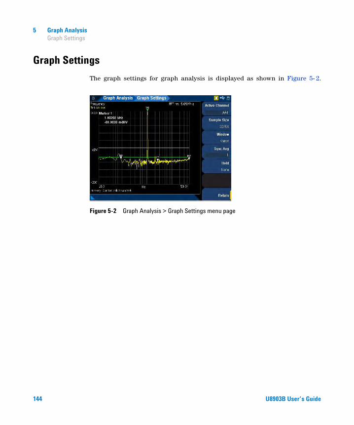
5 Graph Analysis Graph Settings
Graph Settings
The graph settings for graph analysis is displayed as shown in Figure 5- 2.
Figure 5-2 Graph Analysis > Graph Settings menu page
144 U8903B User’s Guide
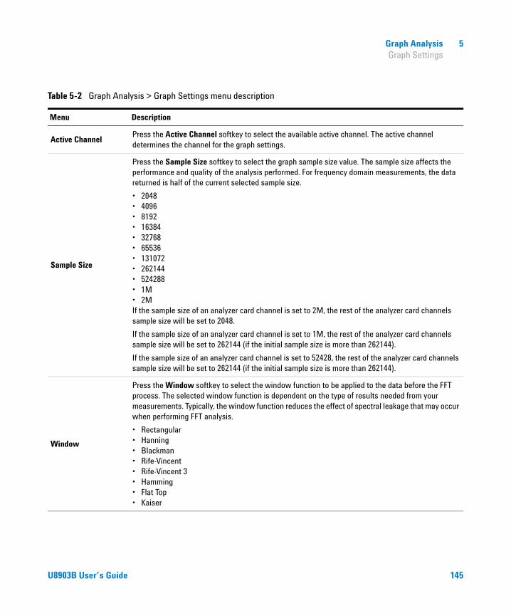
Graph Analysis 5 Graph Settings
Table 5-2 Graph Analysis > Graph Settings menu description
Menu Description
Active ChannelPress the Active Channel softkey to select the available active channel. The active channel determines the channel for the graph settings.
Sample Size
Press the Sample Size softkey to select the graph sample size value. The sample size affects the performance and quality of the analysis performed. For frequency domain measurements, the data returned is half of the current selected sample size.
• 2048• 4096• 8192• 16384• 32768• 65536• 131072• 262144• 524288• 1M• 2MIf the sample size of an analyzer card channel is set to 2M, the rest of the analyzer card channels sample size will be set to 2048.
If the sample size of an analyzer card channel is set to 1M, the rest of the analyzer card channels sample size will be set to 262144 (if the initial sample size is more than 262144).
If the sample size of an analyzer card channel is set to 52428, the rest of the analyzer card channels sample size will be set to 262144 (if the initial sample size is more than 262144).
Window
Press the Window softkey to select the window function to be applied to the data before the FFT process. The selected window function is dependent on the type of results needed from your measurements. Typically, the window function reduces the effect of spectral leakage that may occur when performing FFT analysis.
• Rectangular• Hanning• Blackman• Rife-Vincent• Rife-Vincent 3• Hamming• Flat Top• Kaiser
U8903B User’s Guide 145

5 Graph Analysis Graph Settings
Sync AvgPress the Sync Avg softkey to set the number of samples to be acquired and averaged before the FFT process is performed.
Hold
Press the Hold softkey to select the type of hold to be performed after the FFT process.
• None If None is selected, the latest data will always be displayed.
• Average The Average hold will average both the current and previous data.
• Min The Min hold will compare the current data with the previous data and retains whichever value that is lower.
• Max The Max hold will compare the current data with the previous data and retain whichever value that is higher.
Table 5-2 Graph Analysis > Graph Settings menu description (continued)
Menu Description
146 U8903B User’s Guide

Graph Analysis 5 Axis Settings
Axis Settings
The axis settings for graph analysis is displayed as shown in Figure 5- 3.
Figure 5-3 Graph Analysis > Axis Settings menu page 1
Table 5-3 Graph Analysis > Axis Settings menu description
Menu Description
AxisPress the Axis softkey to select the active axis to be configured.
• Primary• Secondary
EnabledPress the Enabled softkey to enable or disable the axis settings. This setting is only available when the axis type is secondary. If the axis type is primary, this setting is always set to On.
LeftPress the Left softkey to set the left axis limit value. If the value entered is more than the right value, the right value will automatically be set to a value of (Left + 10).
RightPress the Right softkey to set the right axis limit value. If the value entered is more than the left value, the left value will automatically be set to a value of (Right – 10).
Span Press the Span softkey to set the total X-axis span or total range to be monitored in the graph.
Center Press the Center softkey to set the X-axis center point in the graph.
U8903B User’s Guide 147

5 Graph Analysis Axis Settings
TopPress the Top softkey to set the top axis limit value. If the value entered is less than the bottom value, the bottom value will automatically be set to a value of (Top – 10).
BottomPress the Bottom softkey to set the bottom axis limit value. If the value entered is more than the top value, the top value will automatically be set to a value of (Bottom + 10).
X-Scale
Press the X-Scale softkey to select the X-axis scale type. The left and right values must be more than 0 in order to use the log scale.
• Linear• Log
Y-Scale
Press the Y-Scale softkey to select the Y-axis scale type. The bottom and top values must be more than 0 in order to use the log scale.
• Linear• Log
Table 5-3 Graph Analysis > Axis Settings menu description (continued)
Menu Description
148 U8903B User’s Guide
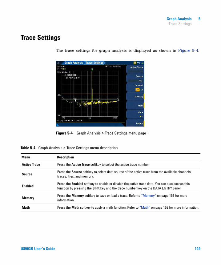
Graph Analysis 5 Trace Settings
Trace Settings
The trace settings for graph analysis is displayed as shown in Figure 5- 4.
Figure 5-4 Graph Analysis > Trace Settings menu page 1
Table 5-4 Graph Analysis > Trace Settings menu description
Menu Description
Active Trace Press the Active Trace softkey to select the active trace number.
SourcePress the Source softkey to select data source of the active trace from the available channels, traces, files, and memory.
EnabledPress the Enabled softkey to enable or disable the active trace data. You can also access this function by pressing the Shift key and the trace number key on the DATA ENTRY panel.
MemoryPress the Memory softkey to save or load a trace. Refer to “Memory” on page 151 for more information.
Math Press the Math softkey to apply a math function. Refer to “Math” on page 152 for more information.
U8903B User’s Guide 149

5 Graph Analysis Trace Settings
Unit
Press the Unit softkey to select the trace unit type.
• V• dBV• dBu• W• dBm• dBSPL
PersistencePress the Persistence softkey to configure the persistence settings. Refer to “Persistence” on page 153 for more information.
Axis
Press the Axis softkey to attach the active trace to the primary or secondary axis. The display of the active trace will reflect on the selected axis.
• Primary• Secondary
Color
Press the Color softkey to select the color of the active trace.
• Yellow• Cyan• White• Pink• Green• Orange• Red• Purple
Table 5-4 Graph Analysis > Trace Settings menu description (continued)
Menu Description
150 U8903B User’s Guide

Graph Analysis 5 Trace Settings
Memory
Figure 5-5 Graph Analysis > Trace Settings > Memory menu page
Table 5-5 Graph Analysis > Trace Settings > Memory menu description
Menu Description
Save To MemoryPress the Save To Memory softkey to save the active trace to the memory buffer[1]. The trace in the memory buffer can be loaded into any other traces. The memory buffer icon will be displayed at the top of the display when there is a trace saved in the memory buffer as shown inTable 1-4.
Load From MemoryPress the Load From Memory softkey to load a trace from the memory buffer into the active trace. An error will be displayed if this softkey is pressed when there is no trace in the memory buffer.
Clear Memory Press the Clear Memory softkey to clear the trace from the memory buffer.
[1] Files saved in the internal volatile memory will be erased after power cycle or reset (refer to “Preset” on page 44).
U8903B User’s Guide 151

5 Graph Analysis Trace Settings
Math
Figure 5-6 Graph Analysis > Trace Settings > Math menu page
Table 5-6 Graph Analysis > Trace Settings > Math menu description
Menu Description
Apply MathPress the Apply Math softkey to apply the corresponding math function to the trace data or turn off the math function.
Function
Press the Function softkey to select the math function to be applied on the active trace.
• None• f(Source) + x• f(Source) - x• f(Source) * x• f(Source) / x
Variable Press the Variable softkey to set the x value in the selected math function.
152 U8903B User’s Guide

Graph Analysis 5 Trace Settings
Persistence
Figure 5-7 Graph Analysis > Trace Settings > Persistence menu page
Table 5-7 Graph Analysis > Trace Settings > Persistence menu description
Menu Description
Persist
Press the Persist softkey to enable or disable persistence on the active trace. Persistence allows you to view the previous sets of trace data in the graph before they are removed. The previous trace data will be displayed in a lighter shade color of the active trace to distinguish between the previous and updated trace data.
Persist Count
Press the Persist Count softkey to set the number of previous sets of trace data to be displayed in the graph before they are removed. For example, a value of 5 indicates that up to a total of 5 previous sets of trace data will be displayed in the graph before they are removed.
This setting is only available when persistence is enabled.
U8903B User’s Guide 153
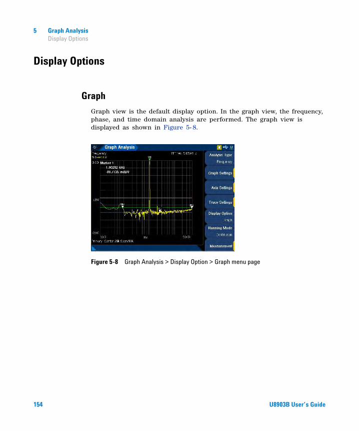
5 Graph Analysis Display Options
Display Options
Graph
Graph view is the default display option. In the graph view, the frequency, phase, and time domain analysis are performed. The graph view is displayed as shown in Figure 5- 8.
Figure 5-8 Graph Analysis > Display Option > Graph menu page
154 U8903B User’s Guide

Graph Analysis 5 Display Options
Data table
In the data table view, you can observe the individual data points in a table format with up to a maximum of four different traces without scrolling. The data table view is displayed as shown in Figure 5- 9. Press the up or down arrow keys to scroll up or down the data points in the table.
Figure 5-9 Graph Analysis > Display Option > DataTable menu page
U8903B User’s Guide 155

5 Graph Analysis Display Options
Marker table
In the marker table view, you can observe the marker and cross- marker calculation information in a table format. The delta marker readings are also listed in the table. The marker table view is displayed as shown in Figure 5- 10.
Figure 5-10 Graph Analysis > Display Option > Marker Table menu page
156 U8903B User’s Guide

Graph Analysis 5 Display Options
Statistics
In the statistics view, the typical statistics calculations are listed down. The available statistics functions are minimum, maximum, standard deviation, and average. The statistics view is displayed as shown in Figure 5- 11.
Figure 5-11 Graph Analysis > Display Option > Statistics menu page
U8903B User’s Guide 157

5 Graph Analysis Display Options
Harmonics
In the harmonics view, you can view and perform harmonic analysis. Information such as the fundamental frequency amplitude and the respective harmonics can be observed in a bar chart. You can also observe the THD information for the individual channels. The harmonics display is displayed as shown in Figure 5- 12.
Figure 5-12 Graph Analysis > Display Option > Harmonics menu page
Press the Harm Settings softkey to configure the harmonics settings. This setting is only available when the graph analysis display option is Harmonics.
158 U8903B User’s Guide

Graph Analysis 5 Display Options
Figure 5-13 Graph Analysis > Harm Settings menu page (Harmonics display)
Table 5-8 Graph Analysis > Harm Settings menu description (Harmonics display)
Menu Description
Active Channel Press the Active Channel softkey to select the active channel.
Odd Harmonics
Press the Odd Harmonics softkey to select the odd harmonics.
• ALL• 3• 5• 7• 9
Even Harmonics
Press the Even Harmonics to select the even harmonics.
• ALL• 2• 4• 6• 8
U8903B User’s Guide 159

5 Graph Analysis Display Options
DisplayPress the Display softkey to select the type of harmonic analysis data to be displayed.
• Harmonics• THD
THD unitPress the THD unit softkey to select the unit for THD measurements.
• dB• %
Table 5-8 Graph Analysis > Harm Settings menu description (continued)(Harmonics display)
Menu Description
160 U8903B User’s Guide

Graph Analysis 5 Display Options
Signal analysis
In the signal analysis view, you can view the analyzer and generator channel information. The signal analysis display is displayed as shown in Figure 5- 14.
Figure 5-14 Graph Analysis > Display Option > Signal Analysis menu page
U8903B User’s Guide 161

5 Graph Analysis Measurement Settings
Measurement Settings
The U8903B allows you to observe up to two measurements running simultaneously in the graph analysis mode. The measurements will be displayed at the bottom of the graph. The measurement settings for graph analysis is displayed as shown in Figure 5- 15.
Figure 5-15 Graph Analysis > Measurement menu page
Table 5-9 Graph Analysis > Measurement menu description
Menu Description
EnabledPress the Enabled softkey to enable or disable the measurements in the graph. If measurement is not required, disable the measurements for better performance.
Measurement 1Press the Measurement 1 softkey to configure the measurement 1 parameters. Refer to “Measurement 1/Measurement 2” on page 163 for more information.
Measurement 2Press the Measurement 2 softkey to configure the measurement 2 parameters. Refer to “Measurement 1/Measurement 2” on page 163 for more information.
162 U8903B User’s Guide
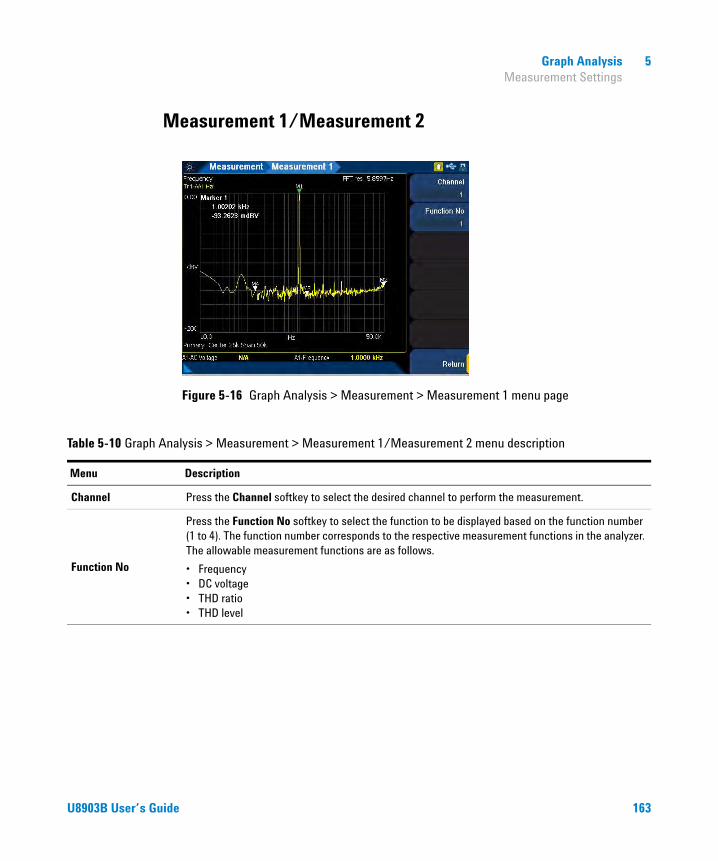
Graph Analysis 5 Measurement Settings
Measurement 1/Measurement 2
Figure 5-16 Graph Analysis > Measurement > Measurement 1 menu page
Table 5-10 Graph Analysis > Measurement > Measurement 1/Measurement 2 menu description
Menu Description
Channel Press the Channel softkey to select the desired channel to perform the measurement.
Function No
Press the Function No softkey to select the function to be displayed based on the function number (1 to 4). The function number corresponds to the respective measurement functions in the analyzer. The allowable measurement functions are as follows.
• Frequency• DC voltage• THD ratio• THD level
U8903B User’s Guide 163

5 Graph Analysis Measurement Settings
THIS PAGE HAS BEEN INTENTIONALLY LEFT BLANK.
164 U8903B User’s Guide

U8903B Audio AnalyzerUser’s Guide
6Sweep Function
Sweep Parameter 166Points settings 168Sweep channels 170
Plot View 171Axis settings 172Plot settings 173
Edit Points 175
This chapter describes the U8903B sweep parameter and the configurations.
165Agilent Technologies

6 Sweep Function Sweep Parameter
Sweep Parameter
The U8903B sweep mode allows you to perform sweeps and to display the results in a plot view. Press on the FUNCTION panel to access the sweep mode. The Sweep Parameter menu page is the default page and is displayed as shown in Figure 6- 1. There are three main panels on the Sweep Parameter menu page. The top panel displays the current sweep settings and the bottom panels display the analog generator and analog analyzer settings respectively. Use the arrow keys to navigate among the panels.
Press on the RUN CONTROL panel to start or stop the sweep in the sweep mode.
Figure 6-1 Sweep Parameter menu page
NOTE The U8903B sweep mode is only available in the Standard View mode. Refer to “Menu key” on page 25 for more information.
Sweep
OnOff
166 U8903B User’s Guide
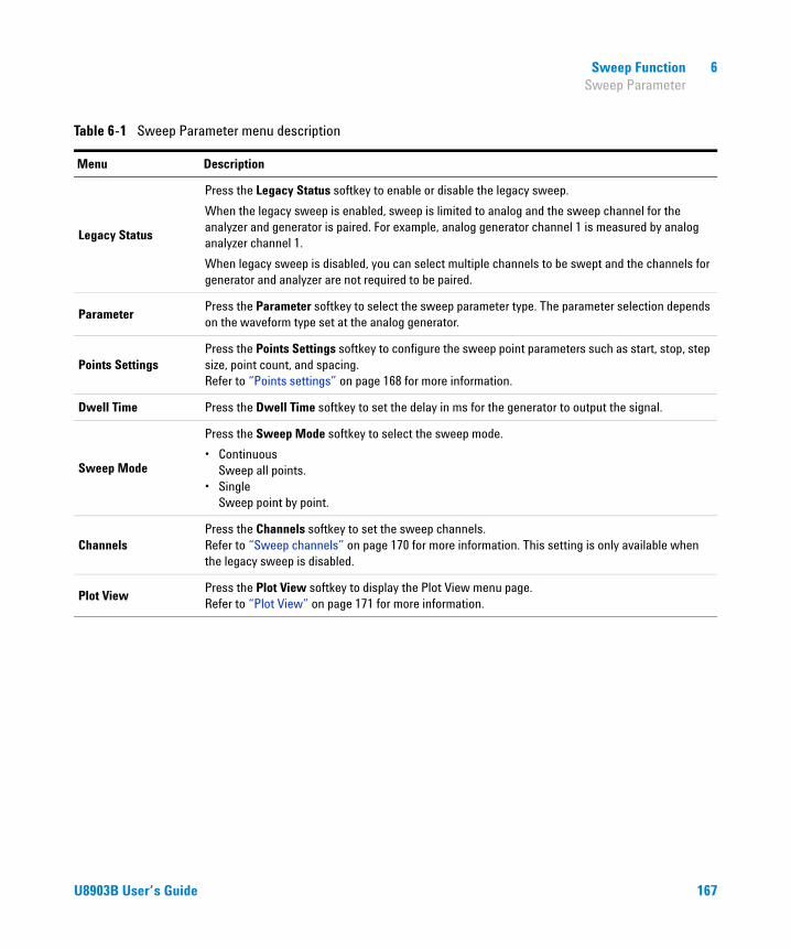
Sweep Function 6 Sweep Parameter
Table 6-1 Sweep Parameter menu description
Menu Description
Legacy Status
Press the Legacy Status softkey to enable or disable the legacy sweep.
When the legacy sweep is enabled, sweep is limited to analog and the sweep channel for the analyzer and generator is paired. For example, analog generator channel 1 is measured by analog analyzer channel 1.
When legacy sweep is disabled, you can select multiple channels to be swept and the channels for generator and analyzer are not required to be paired.
ParameterPress the Parameter softkey to select the sweep parameter type. The parameter selection depends on the waveform type set at the analog generator.
Points SettingsPress the Points Settings softkey to configure the sweep point parameters such as start, stop, step size, point count, and spacing. Refer to “Points settings” on page 168 for more information.
Dwell Time Press the Dwell Time softkey to set the delay in ms for the generator to output the signal.
Sweep Mode
Press the Sweep Mode softkey to select the sweep mode.
• Continuous Sweep all points.
• Single Sweep point by point.
ChannelsPress the Channels softkey to set the sweep channels. Refer to “Sweep channels” on page 170 for more information. This setting is only available when the legacy sweep is disabled.
Plot ViewPress the Plot View softkey to display the Plot View menu page. Refer to “Plot View” on page 171 for more information.
U8903B User’s Guide 167

6 Sweep Function Sweep Parameter
Points settings
Figure 6-2 Sweep Parameter > Points Settings menu page 1
Table 6-2 Sweep Parameter > Points Settings menu description
Menu Description
Spacing
Press the Spacing softkey to select the spacing type.
• Log – Geometric series
• Linear – Arithmetic series
• Custom – Arbitrary spacing
Step size 10
10StopStart------------⎝ ⎠⎛ ⎞log
Points 1–( )--------------------------
=
Step sizeStart Stop–( )Points 1–( )
-------------------------------------=
168 U8903B User’s Guide

Sweep Function 6 Sweep Parameter
Unit
Press the Unit softkey to select the sweep unit. This setting is only available when the sweep parameter is amplitude.
• Vrms• dBV• Vp• Vpp• dBm• dBu• dBSPL
StartPress the Start softkey to set the sweep start value. This setting is only available when the sweep spacing is Log or Linear.
StopPress the Stop softkey to set the sweep stop value. This setting is only available when the sweep spacing is Log or Linear.
StepPress the Step softkey to set the sweep step value. Adjusting the sweep step value will change the sweep points value. This setting is only available when the sweep spacing is Log or Linear.
PointsPress the Points softkey to set the sweep points value. Adjusting the sweep points value will change the sweep step value. This setting is only available when the sweep spacing is Log or Linear.
Edit PointsPress the Edit Points softkey to configure the sweep points. Refer to “Edit Points” on page 175 for more information. If the sweep points are changed, the sweep spacing mode will be set to Custom.
Table 6-2 Sweep Parameter > Points Settings menu description (continued)
Menu Description
U8903B User’s Guide 169

6 Sweep Function Sweep Parameter
Sweep channels
Figure 6-3 Sweep Parameter > Channels menu page
NOTE This setting is only available when the legacy sweep is disabled.
Table 6-3 Sweep Parameter > Channels menu description
Menu Description
Source Press the Source softkey to select the source channel(s).
MeasurePress the Measure softkey to select the measure channel(s). The available selection depends on the number of installed analog analyzer cards.
170 U8903B User’s Guide

Sweep Function 6 Plot View
Plot View
The sweep plot view menu page is displayed as shown in Figure 6- 4.
Press on the RUN CONTROL panel to start or stop the sweep in the sweep mode.
Figure 6-4 Sweep > Plot View menu page
OnOff
Table 6-4 Sweep > Plot View menu description
Menu Description
Axis SettingsPress the Axis Settings softkey to configure the sweep axis settings. Refer to “Axis settings” on page 172 for more information.
Plot SettingsPress the Plot Settings softkey to configure the sweep trace settings. Refer to “Plot settings” on page 173 for more information.
Edit PointsPress the Edit Points softkey to configure the sweep points. Refer to “Edit Points” on page 175 for more information.
Save PtsPress the Save Pts softkey to save the sweep points to a file. Refer to “Save” on page 61 for the Save menu page.
U8903B User’s Guide 171
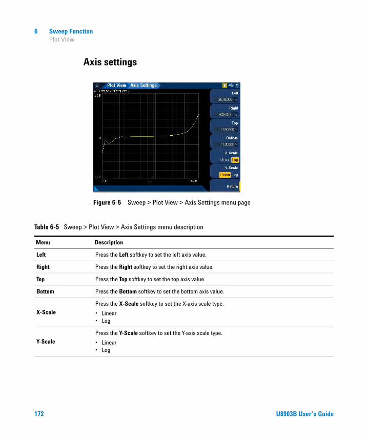
6 Sweep Function Plot View
Axis settings
Figure 6-5 Sweep > Plot View > Axis Settings menu page
Table 6-5 Sweep > Plot View > Axis Settings menu description
Menu Description
Left Press the Left softkey to set the left axis value.
Right Press the Right softkey to set the right axis value.
Top Press the Top softkey to set the top axis value.
Bottom Press the Bottom softkey to set the bottom axis value.
X-ScalePress the X-Scale softkey to set the X-axis scale type.
• Linear• Log
Y-ScalePress the Y-Scale softkey to set the Y-axis scale type.
• Linear• Log
172 U8903B User’s Guide

Sweep Function 6 Plot View
Plot settings
Figure 6-6 Sweep > Plot View > Plot Settings menu page
Table 6-6 Sweep > Plot View > Plot Settings menu description
Menu Description
Data ChannelPress the Data Channel softkey to select the trace data channel number to be plotted. This setting is only available when the measured channels are more than one channel.
Y Data
Press the Y Data softkey to select the Y-axis trace data source.
• S: <sweep parameter>• F1: <measurement function 1>• F2: <measurement function 2>• F3: <measurement function 3>• F4: <measurement function 4>
U8903B User’s Guide 173
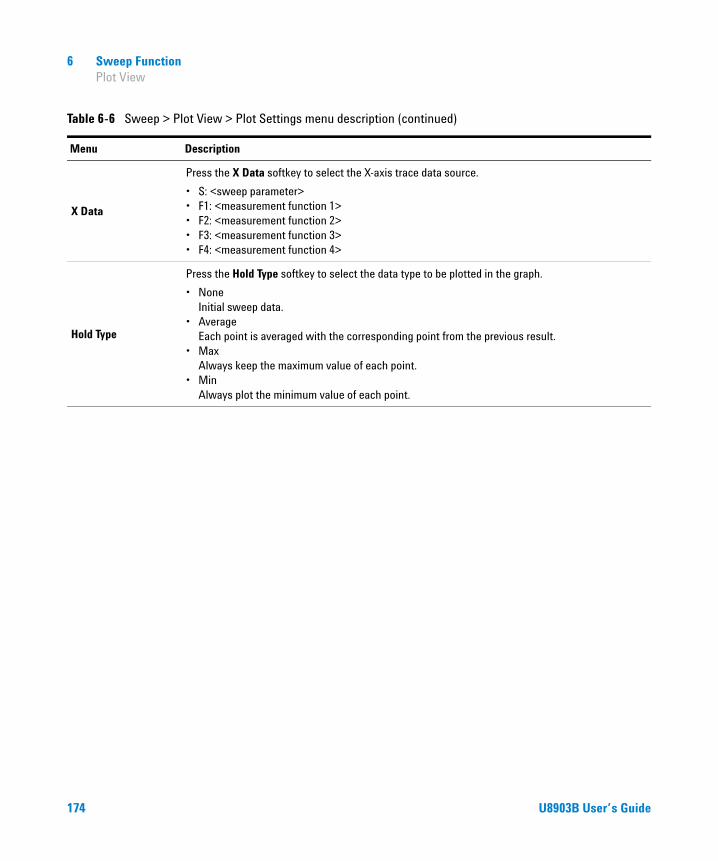
6 Sweep Function Plot View
X Data
Press the X Data softkey to select the X-axis trace data source.
• S: <sweep parameter>• F1: <measurement function 1>• F2: <measurement function 2>• F3: <measurement function 3>• F4: <measurement function 4>
Hold Type
Press the Hold Type softkey to select the data type to be plotted in the graph.
• None Initial sweep data.
• Average Each point is averaged with the corresponding point from the previous result.
• Max Always keep the maximum value of each point.
• Min Always plot the minimum value of each point.
Table 6-6 Sweep > Plot View > Plot Settings menu description (continued)
Menu Description
174 U8903B User’s Guide

Sweep Function 6 Edit Points
Edit Points
Figure 6-7 Sweep > Edit Points menu page 1
Table 6-7 Sweep > Edit Points menu description
Menu Description
Data ChannelPress the Data Channel softkey to select the trace data channel number to be plotted. This setting is only available when the measured channels are more than one channel.
Goto PointPress the Goto Point softkey to set the sweep point number to go to. The sweep point number will be highlighted. You can also use the arrow keys to select the desired sweep point.
Point Value Press the Point Value softkey to set the currently selected sweep point value.
Add Point Press the Add Point softkey to add a sweep point.
Remove Point Press the Remove Point softkey to remove the selected sweep point.
Load PointsPress the Load Points softkey to load the sweep points from a file. Refer to “Recall” on page 62 for the Recall menu page.
Save PointsPress the Save Points softkey to save the sweep points to a file. Refer to “Save” on page 61 for the Save menu page.
NOTE If the sweep points are changed, the sweep spacing mode will be set to Custom. Refer to Table 6-2 for more information.
U8903B User’s Guide 175

6 Sweep Function Edit Points
THIS PAGE HAS BEEN INTENTIONALLY LEFT BLANK.
176 U8903B User’s Guide

U8903B Audio AnalyzerUser’s Guide
7Test Sequence Application
Test Sequence Application 179
Project 181
Test Sequence 183
IO Configuration 184Settings 185Properties 190
Sub-steps 191Prompt sub-step settings 193Send SCPI sub-step settings 195
Measurements 197Properties 199AC level 201Frequency 206Phase 210SNR 214THD+N 221DC level 226Crosstalk 230SMPTE IMD 234DFD IMD 239Multitone analyzer 243Stepped frequency sweep 247SMPTE frequency sweep 252DFD frequency sweep 256Stepped level sweep 261SMPTE level sweep 267DFD level sweep 271DC level sweep 275RF power sweep 280Measurement recorder 287
177Agilent Technologies
7 Test Sequence Application
POLQA 293
Measurement Results 297
Report 303Properties 304
This chapter describes the various configurations for the U8903B test sequence application.
178 U8903B User’s Guide

Test Sequence Application 7 Test Sequence Application
Test Sequence Application
The U8903B test sequence application (Test Seq App) mode allows you to create a series of automated measurements on a DUT. You can customize the order in which the measurements are performed, edit the pass or fail limits, add sub steps, and create a detailed report of the measurements.
There are two main tabs in the test sequence application mode — Project tab and Report tab.
The Project tab allows you to add up to 20 test sequence and configure the measurements in each test sequence. The Report tab allows you to display all the measurements results and generate a report.
Use the left and right arrow keys to switch between the Project tab or Report tab. Refer to “Project” on page 181 and “Report” on page 303 for more information.
An example of the Project tab menu page is as shown in Figure 7- 1.
Figure 7-1 TSA > Project menu page
U8903B User’s Guide 179

7 Test Sequence Application Test Sequence Application
Press to start or stop the test sequence. The Test Application menu page will be displayed as shown in Figure 7- 2.
Figure 7-2 Test Application menu page
OnOff
Table 7-1 Test Application menu description
Menu Description
Start Test App Press the Start Test App softkey to start the test application project.
Start Test App From Here
Press the Start Test App From Here softkey to start the test application from the selected test or measurement tab.
This setting is only available when the On/Off key is pressed with the test or measurement tab selected.
Start Selected Measurement
Press the Start Selected Measurement softkey to start the test for the selected measurement.
This setting is only available when the On/Off key is pressed with the measurement tab selected.
180 U8903B User’s Guide

Test Sequence Application 7 Project
Project
The TSA > Project menu page is displayed as shown in Figure 7- 3.
Figure 7-3 TSA > Project menu page
Press the up or down arrow key to select the test sequence, IO configuration, or measurements tabs. The respective menu page will be displayed. Refer to “Test Sequence” on page 183, “IO Configuration” on page 184, and “Measurements” on page 197 for more information.
Table 7-2 TSA > Project menu description
Menu Description
New Project Press the New Project softkey to create a new project.
Open ProjectPress the Open Project softkey to load a project from a file. Refer to “Recall” on page 62 for more information on the Recall menu page.
Save ProjectPress the Save Project softkey to save the project to a file. Refer to “Save” on page 61 for more information on the Save menu page.
PropertiesPress the Properties softkey to configure the project properties. Refer to “Properties” on page 182 for more information on the Properties menu page.
U8903B User’s Guide 181
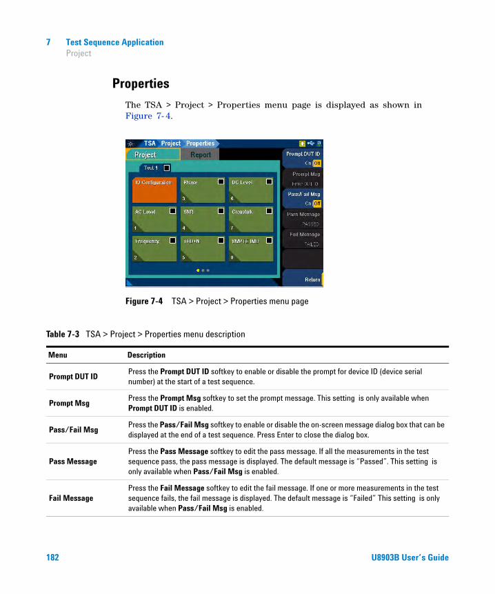
7 Test Sequence Application Project
Properties
The TSA > Project > Properties menu page is displayed as shown in Figure 7- 4.
Figure 7-4 TSA > Project > Properties menu page
Table 7-3 TSA > Project > Properties menu description
Menu Description
Prompt DUT IDPress the Prompt DUT ID softkey to enable or disable the prompt for device ID (device serial number) at the start of a test sequence.
Prompt MsgPress the Prompt Msg softkey to set the prompt message. This setting is only available when Prompt DUT ID is enabled.
Pass/Fail MsgPress the Pass/Fail Msg softkey to enable or disable the on-screen message dialog box that can be displayed at the end of a test sequence. Press Enter to close the dialog box.
Pass MessagePress the Pass Message softkey to edit the pass message. If all the measurements in the test sequence pass, the pass message is displayed. The default message is “Passed”. This setting is only available when Pass/Fail Msg is enabled.
Fail MessagePress the Fail Message softkey to edit the fail message. If one or more measurements in the test sequence fails, the fail message is displayed. The default message is “Failed” This setting is only available when Pass/Fail Msg is enabled.
182 U8903B User’s Guide

Test Sequence Application 7 Test Sequence
Test Sequence
The TSA > Project > Test menu page is displayed as shown in Figure 7- 5.
Figure 7-5 TSA > Project > Test menu page
Table 7-4 TSA > Project > Test menu description
Menu Description
StatusPress the Status softkey to enable or disable the selected test sequence. The check boxes for the test and all the measurements in the test will be selected when enabled.
Add Test Sequence
Press the Add Test Sequence softkey to add a test sequence.
• New Add a new test sequence.
• Saved Load a saved test sequence file. Refer to “Recall” on page 62 for more information on the Recall menu page.
Delete Test Sequence Press the Delete Test Sequence softkey to delete the selected test sequence.
SavePress the Save softkey to save the test sequence to a file. Refer to “Save” on page 61 for more information on the Save menu page.
EditPress the Edit softkey to move or copy the selected test sequence, or paste a copied test sequence after the selected test sequence.
Properties Press the Properties softkey to set the test sequence name.
U8903B User’s Guide 183

7 Test Sequence Application IO Configuration
IO Configuration
The IO Configuration tab allows you to configure the output and input settings. There will be one IO Configuration tab in each test sequence. The settings configured in the IO configuration will be applied to all the measurements in the test sequence. The TSA > Project > Test > IO Configuration menu page is displayed as shown in Figure 7- 6.
Figure 7-6 TSA > Project > Test > IO Configuration menu page
Table 7-5 TSA > Project > Test > IO Configuration menu description
Menu Description
Add MeasurementPress the Add Measurement softkey to add measurements to the selected test sequence. Refer to “Measurements” on page 197 for more information.
EditPress the Edit softkey to paste a copied measurement after the IO configuration. The IO Configuration cannot be moved or copied.
SettingsPress the Settings softkey to configure the IO settings. Refer to “Settings” on page 185 for more information.
PropertiesPress the Properties softkey to configure the IO configuration properties. Refer to “Properties” on page 190 for more information.
184 U8903B User’s Guide
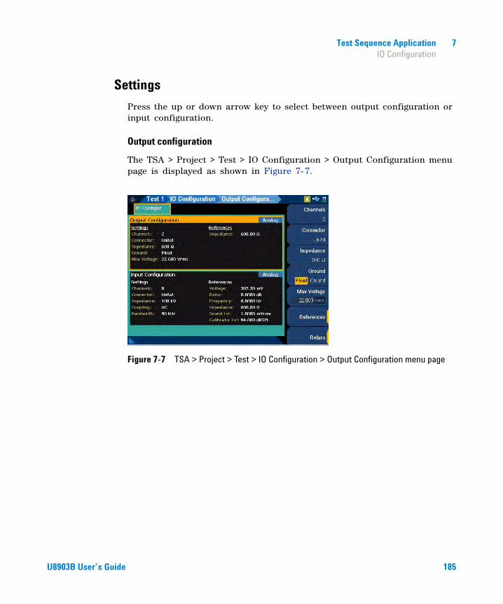
Test Sequence Application 7 IO Configuration
Settings
Press the up or down arrow key to select between output configuration or input configuration.
Output configuration
The TSA > Project > Test > IO Configuration > Output Configuration menu page is displayed as shown in Figure 7- 7.
Figure 7-7 TSA > Project > Test > IO Configuration > Output Configuration menu page
U8903B User’s Guide 185
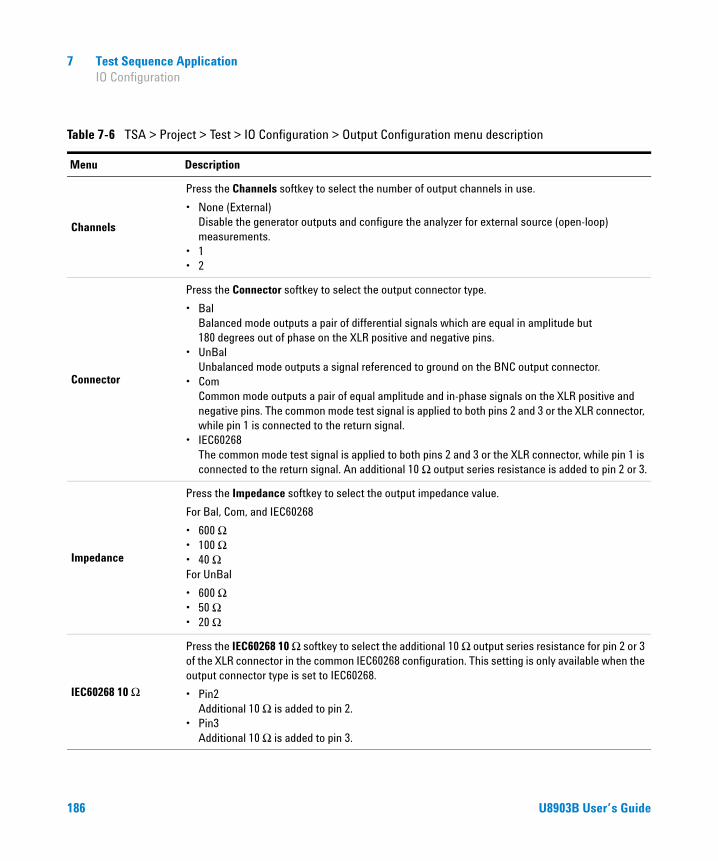
7 Test Sequence Application IO Configuration
Table 7-6 TSA > Project > Test > IO Configuration > Output Configuration menu description
Menu Description
Channels
Press the Channels softkey to select the number of output channels in use.
• None (External) Disable the generator outputs and configure the analyzer for external source (open-loop) measurements.
• 1• 2
Connector
Press the Connector softkey to select the output connector type.
• Bal Balanced mode outputs a pair of differential signals which are equal in amplitude but 180 degrees out of phase on the XLR positive and negative pins.
• UnBal Unbalanced mode outputs a signal referenced to ground on the BNC output connector.
• Com Common mode outputs a pair of equal amplitude and in-phase signals on the XLR positive and negative pins. The common mode test signal is applied to both pins 2 and 3 or the XLR connector, while pin 1 is connected to the return signal.
• IEC60268 The common mode test signal is applied to both pins 2 and 3 or the XLR connector, while pin 1 is connected to the return signal. An additional 10 Ω output series resistance is added to pin 2 or 3.
Impedance
Press the Impedance softkey to select the output impedance value.
For Bal, Com, and IEC60268
• 600 Ω• 100 Ω• 40 ΩFor UnBal
• 600 Ω• 50 Ω• 20 Ω
IEC60268 10 Ω
Press the IEC60268 10 Ω softkey to select the additional 10 Ω output series resistance for pin 2 or 3 of the XLR connector in the common IEC60268 configuration. This setting is only available when the output connector type is set to IEC60268.
• Pin2 Additional 10 Ω is added to pin 2.
• Pin3 Additional 10 Ω is added to pin 3.
186 U8903B User’s Guide

Test Sequence Application 7 IO Configuration
Input configuration
The TSA > Project > Test > IO Configuration > Input Configuration menu page is displayed as shown in Figure 7- 8.
Figure 7-8 TSA > Project > Test > IO Configuration > Input Configuration menu page
Ground
Press the Ground softkey to select the grounding type.
• Float In the floating grounding type, the signal return line (XLR pin 1 for balanced output or BNC return for unbalanced output) is not grounded to the chassis earth and is “floating”.
• Ground In the ground grounding type, the signal return line (XLR pin 1 for balanced output or BNC return for unbalanced output) is connected to the chassis earth.
Max VoltagePress the Max Voltage softkey to set the maximum voltage. The maximum voltage value set will limit the maximum amplitude output from the generator and prevent any excessive high voltage values from damaging the DUT.
ReferencePress the Reference softkey to set the output references for generator.
• Impedance Set the reference impedance for the unit conversion of dBm measurements.
Table 7-6 TSA > Project > Test > IO Configuration > Output Configuration menu description (continued)
Menu Description
U8903B User’s Guide 187

7 Test Sequence Application IO Configuration
Table 7-7 TSA > Project > Test > IO Configuration > Input Configuration menu description
Menu Description
Channels Press the Channels softkey to select the number of input channels in use.
Connector
Press the Connector softkey to select the input connector type.
• UnBal Unbalanced connector type routes the signal from the BNC input connector. The signal in the inner conductor of the coaxial connector is referenced to the ground for measurement.
• Bal Balanced connector type routes the signal from the XLR input connectors in the front panel to the analog analyzer. The signals on the positive and negative pins of the XLR connector enter a differential amplifier where they are subtracted before passing on to the detector.
• Loopback Loopback connector type routes the signal from the generator to the analyzer internally. The generator channel 1 signal will be routed to the analyzer odd channels (1, 3, 5, and 7), and the generator channel 2 signal will be routed to the analyzer even channels (2, 4, 6, and 8). For example, if you select Loopback in any of the analyzer odd channels, the output connector type of the generator channel 1 will automatically be set to Loopback.
Impedance
Press the Impedance softkey to select the input impedance value. This setting is only available when Connector is set to UnBal or Bal.
• 100 kΩ (for Unbalanced)• 200 kΩ (for Balanced)• 600 Ω• 300 Ω
Coupling
Press the Coupling softkey to select the input coupling type.
• DC DC coupling allows both the AC and DC analog input signals to pass through to the analog analyzer and to be measured down to 0 Hz. This setting should be selected when making DC voltage measurements.
• AC AC coupling blocks the DC component of the analog input signal by switching a capacitor in series to the input path. This setting should be selected when you need to measure only the AC component of a signal. For example, use AC coupling when you are making an rms or peak-to-peak voltage measurement.
188 U8903B User’s Guide

Test Sequence Application 7 IO Configuration
Bandwidth
Press the Bandwidth softkey to select the input bandwidth value.
• 90 kHz (This is the default setting with sampling rate of 192 kHz)
• 1.5 MHz This setting is only available with Option N3431A. Refer to “U8903B Options” on page 5 for more information.
Reference
Press the Reference softkey to set the input references for analyzer.
• Voltage• Ratio• Frequency• Impedance• Sound level• Calibrator level
Table 7-7 TSA > Project > Test > IO Configuration > Input Configuration menu description (continued)
Menu Description
U8903B User’s Guide 189
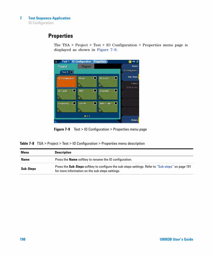
7 Test Sequence Application IO Configuration
Properties
The TSA > Project > Test > IO Configuration > Properties menu page is displayed as shown in Figure 7- 9.
Figure 7-9 Test > IO Configuration > Properties menu page
Table 7-8 TSA > Project > Test > IO Configuration > Properties menu description
Menu Description
Name Press the Name softkey to rename the IO configuration.
Sub-StepsPress the Sub-Steps softkey to configure the sub-steps settings. Refer to “Sub-steps” on page 191 for more information on the sub-steps settings.
190 U8903B User’s Guide
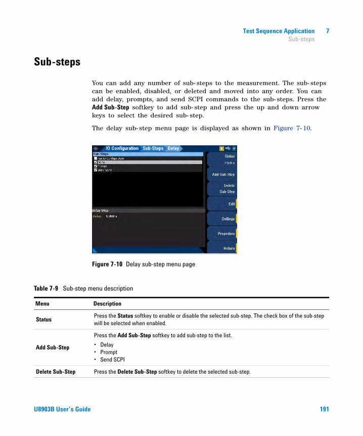
Test Sequence Application 7 Sub-steps
Sub-steps
You can add any number of sub- steps to the measurement. The sub- steps can be enabled, disabled, or deleted and moved into any order. You can add delay, prompts, and send SCPI commands to the sub- steps. Press the Add Sub-Step softkey to add sub- step and press the up and down arrow keys to select the desired sub- step.
The delay sub- step menu page is displayed as shown in Figure 7- 10.
Figure 7-10 Delay sub-step menu page
Table 7-9 Sub-step menu description
Menu Description
StatusPress the Status softkey to enable or disable the selected sub-step. The check box of the sub-step will be selected when enabled.
Add Sub-Step
Press the Add Sub-Step softkey to add sub-step to the list.
• Delay• Prompt• Send SCPI
Delete Sub-Step Press the Delete Sub-Step softkey to delete the selected sub-step.
U8903B User’s Guide 191
7 Test Sequence Application Sub-steps
EditPress the Edit softkey to move or copy the selected sub-step, or paste a copied sub-step after the selected sub-step.
Settings
Press the Settings softkey to configure the sub-step settings.
• Delay Set the delay time in seconds. Minimum: 0 s Maximum: 3600 s (1 hour)
• Prompt Refer to “Prompt sub-step settings” on page 193 for more information.
• Send SCPI Refer to “Send SCPI sub-step settings” on page 195 for more information.
Properties Press the Properties softkey to rename the sub-step.
Table 7-9 Sub-step menu description (continued)
Menu Description
192 U8903B User’s Guide

Test Sequence Application 7 Sub-steps
Prompt sub-step settings
The prompt sub- step inserts a prompt message with reply option to the measurement. This provides you the information and opportunity to interact with the sequence. Press OK to close the prompt window and continue the test sequence. The prompt sub- step settings menu page is displayed as shown in Figure 7- 11.
Figure 7-11 Prompt sub-step settings menu page
Table 7-10 Prompt sub-step settings menu description
Menu Description
Message Press the Message softkey to set the prompt message at the lower half of the main display.
Prompt Icon
Press the Prompt Icon softkey to select the prompt icon to be displayed.
• None• Hand• Question• Exclamation• Asterisk
U8903B User’s Guide 193
7 Test Sequence Application Sub-steps
Dialog Settings
Press the Dialog Settings softkey to add additional settings to the prompt window.
• Timeout When selected, the timeout value sets the maximum prompt window display time, in seconds. If the timeout is reached, the current measurement fails. When unselected, the prompt window will remain open until user closes it.
• Cancel When selected, a Cancel button will be added to the prompt window. Press the Cancel button to close the prompt window and stop the test sequence.
Timeout
Press the Timeout softkey to set the prompt timeout value in seconds. This setting is only available if Timeout is selected in the dialog settings.
Minimum: 1 s Maximum: 3600 s (1 hour)
Table 7-10 Prompt sub-step settings menu description (continued)
Menu Description
194 U8903B User’s Guide
Test Sequence Application 7 Sub-steps
Send SCPI sub-step settings
The send SCPI sub- step can be inserted into any measurement in the test sequence to issue SCPI command(s) to a connected external instrument and to pause for a specified delay time after the command(s) is issued. This sub- step is useful for setting up an external instrument connected through a USB/GPIB interface before a measurement is performed. The send SCPI sub- step settings menu page is displayed as shown in Figure 7- 12.
Figure 7-12 Send SCPI sub-step settings menu page
Table 7-11 Send SCPI sub-step settings menu description
Menu Description
GPIB Address Press the GPIB Address softkey to select the desired GPIB address.
SCPI Commands
Press the SCPI Commands softkey to configure the SCPI commands.
• Edit Set the SCPI commands at the lower half of the main display.
• Import Load the SCPI commands from a file. Refer to “Recall” on page 62 for more information on the Recall menu page.
U8903B User’s Guide 195
7 Test Sequence Application Sub-steps
Progress MsgPress the Progress Msg softkey to set the optional text message that will be displayed on a dialog box for the time length set in Delay.
Delay
Press the Delay softkey to set the delay time length after the SCPI command(s) is issued. The SCPI command(s) may start an external event that takes some time to complete. An optional delay time can be set to wait for completion. The next sub-step in the test sequence will not be executed until the delay time has passed.
Table 7-11 Send SCPI sub-step settings menu description (continued)
Menu Description
196 U8903B User’s Guide

Test Sequence Application 7 Measurements
Measurements
The U8903B allows up to 20 results in a single measurement. You can move a selected measurement within the same test sequence. An example of the measurement menu page is displayed as shown in Figure 7- 13.
Figure 7-13 TSA > Project > Test > AC Level menu page
Table 7-12 TSA > Project > Test > Measurement menu description
Menu Description
StatusPress the Status softkey to enable or disable the selected measurement. The check box for the measurement will be selected when enabled.
Add Measurement Press the Add Measurement softkey to add measurements.
Delete Measurement Press the Delete Measurement softkey to delete the selected measurement.
EditPress the Edit softkey to move or copy the selected measurement, or paste a copied measurement after the selected measurement.
U8903B User’s Guide 197

7 Test Sequence Application Measurements
Settings
Press the Settings softkey to configure the selected measurement. Refer to the respective measurement settings for more information.
• AC level• Frequency• Phase• SNR• THD+N• DC level• Crosstalk• SMPTE IMD• DFD IMD• Multitone analyzer• Stepped frequency sweep• SMPTE frequency sweep• DFD frequency sweep• Stepped level sweep• SMPTE level sweep• DFD level sweep• DC level sweep• RF power sweep• Measurement recorder• POLQA
PropertiesPress the Properties softkey to configure the measurement properties. Refer to “Properties” on page 199 for more information.
Table 7-12 TSA > Project > Test > Measurement menu description (continued)
Menu Description
198 U8903B User’s Guide

Test Sequence Application 7 Measurements
Properties
An example of the measurement properties menu page is displayed as shown in Figure 7- 14.
Figure 7-14 TSA > Project > Test > AC Level > Properties menu page
Table 7-13 TSA > Project > Test > Measurement > Properties menu description
Menu Description
Name Press the Name softkey to rename the selected measurement.
Sub-StepsPress the Sub-Steps softkey to configure the sub-steps settings. Refer to “Sub-steps” on page 191 for more information on the sub-steps settings.
U8903B User’s Guide 199

7 Test Sequence Application Measurements
Failure Handling
Press the Failure Handling softkey to select the failure handling type for the selected measurement. When a measurement exceeded its preset limit or faced failure due to improper configuration (for example, calling for a file that does not exist or sending a SCPI sub-step to an unconnected devices), you can direct the application to the following:
• Cancel Seq. Stop the test sequence.
• Allow Retry Display a prompt window with Abort, Retry, and Ignore commands. Abort will immediately stop the test sequence. Retry will rerun the selected measurements. Ignore will flag the measurement as failed and continue with the test sequence.
• Continue Seq. Flag the measurement as failed and continue with the test sequence.
Table 7-13 TSA > Project > Test > Measurement > Properties menu description (continued)
Menu Description
200 U8903B User’s Guide

Test Sequence Application 7 Measurements
AC level
AC level measurement provides a single value measurement of the output level from each DUT channel, as measured at each of the analyzer input. The AC level measurement settings allows you to configure the signal generation and signal analysis settings. The result for the AC level measurement for all the selected channels are displayed in a bar chart (AC Level and Gain). The gain result is not available if None is selected for the output configuration channels. Refer to “Measurement Results” on page 297 for more information on the respective result menu page.
Use the arrow keys to navigate through the respective tabs and to display the menu page.
Signal generation
The AC level signal generation settings menu page is displayed as shown in Figure 7- 15.
Figure 7-15 TSA > Project > Test > AC Level > Settings > Signal Generation menu page
NOTE The signal generation is disabled if None is selected for the output configuration channel.
U8903B User’s Guide 201

7 Test Sequence Application Measurements
Table 7-14 TSA > Project > Test > AC Level > Settings > Signal Generation menu description
Menu Description
Waveform
Press the Waveform softkey to select the waveform type.
• Sine• Variable Phase• Square• Arbitrary
Output Press the Output softkey to select the output channel.
Waveform Config
Press the Waveform Config softkey to set the waveform configuration. The available settings depend on the waveform type.
• Track 1st Ch If Track 1st Ch is enabled, the generator channel 1 waveform configuration settings will be copied to the other channels and the waveform configuration settings for the other channels cannot be edited. Any changes made to channel 1 waveform configuration settings will be reproduced in the other channels waveform configuration settings. Disable the Track 1st Ch to set the individual channels.
• Frequency Set the frequency value.
• Amplitude Set the amplitude value.
• DC Offset Set the DC offset value.
• Phase->1st Ch Set the phase value. This setting is only available when channel 2 is selected.
202 U8903B User’s Guide

Test Sequence Application 7 Measurements
Signal analysis
The AC level signal analysis settings menu page is displayed as shown in Figure 7- 16.
Figure 7-16 TSA > Project > Test > AC Level > Settings > Signal Analysis menu page
Table 7-15 TSA > Project > Test > AC Level > Settings > Signal Analysis menu description
Menu Description
Detector
Press the Detector softkey to select the AC level detector type.
• RMS AC level measurement is expressed in an rms value.
• Pk-Pk AC level measurement is expressed in a Vpp value.
U8903B User’s Guide 203
7 Test Sequence Application Measurements
LPF
Press the LPF softkey to select the low-pass filter.
• None• 2 kHz• 3 kHz• 5 kHz• 8 kHz• 10 kHz• 15 kHz• 20 kHz• 22 kHz• 30 kHz• 40 kHz• 50 kHz• 80 kHz• Custom
Sample Size
Press the Sample Size softkey to select the number of samples to be acquired for the measurement.
• 2048• 4096• 8192• 16384• 32768• 65536• 131072• 262144• 524288• 1M• 2M
Table 7-15 TSA > Project > Test > AC Level > Settings > Signal Analysis menu description (continued)
Menu Description
204 U8903B User’s Guide

Test Sequence Application 7 Measurements
Input Range
Press the Input Range softkey to configure the input range settings.
• Auto Range Enable or disable the auto input range. If auto range is enabled, each analog channel input range is determined automatically, based on the level of the input signal. If the input signal level changes beyond the ranging threshold, auto range will cause the input ranging circuits to move up or down for a proper ranging. If auto range is disabled, you can set a fixed input voltage range for each analog input channel.
• Track 1st Ch If Track 1st Ch is enabled, all the other channels will be set to follow the channel 1 range setting. Any changes made to channel 1 range setting will be reproduced in the other channels. Disable the Track 1st Ch to set the individual channels.
• Voltage Range Set the input voltage range.
Table 7-15 TSA > Project > Test > AC Level > Settings > Signal Analysis menu description (continued)
Menu Description
U8903B User’s Guide 205

7 Test Sequence Application Measurements
Frequency
Frequency measurement provides a single value frequency measurement of the strongest component in the output signal of each DUT channel. The frequency measurement settings allows you to configure the signal generation settings and signal analysis settings.
The result for the frequency measurement for all the selected channels are displayed in a bar chart (Frequency). Refer to “Measurement Results” on page 297 for more information on the respective result menu page. Use the arrow keys to navigate through the respective tabs and to display the menu page.
Signal generation
The frequency signal generation settings menu page is displayed as shown in Figure 7- 17.
Figure 7-17 Frequency > Signal Generation settings menu page
NOTE The signal generation is disabled if None is selected for the output configuration channel.
206 U8903B User’s Guide

Test Sequence Application 7 Measurements
Table 7-16 Frequency > Signal Generation settings menu description
Menu Description
Waveform
Press the Waveform softkey to select the waveform type.
• Sine• Variable Phase• Square• Arbitrary
Output Press the Output softkey to select the output channel.
Waveform Config
Press the Waveform Config softkey to set the waveform configuration. The available settings depend on the waveform type.
• Track 1st Ch If Track 1st Ch is enabled, the generator channel 1 waveform configuration settings will be copied to the other channels and the waveform configuration settings for the other channels cannot be edited. Any changes made to channel 1 waveform configuration settings will be reproduced in the other channels waveform configuration settings. Disable the Track 1st Ch to set the individual channels.
• Frequency Set the frequency value.
• Amplitude Set the amplitude value.
• DC Offset Set the DC offset value.
• Phase->1st Ch Set the phase value. This setting is only available when channel 2 is selected.
U8903B User’s Guide 207

7 Test Sequence Application Measurements
Signal analysis
The frequency signal analysis settings menu page is displayed as shown in Figure 7- 18.
Figure 7-18 Frequency > Signal Analysis settings menu page
Table 7-17 Frequency > Signal Analysis settings menu description
Menu Description
Sample Size
Press the Sample Size softkey to select the number of samples to be acquired for the measurement.
• 2048• 4096• 8192• 16384• 32768• 65536• 131072• 262144• 524288• 1M• 2M
208 U8903B User’s Guide
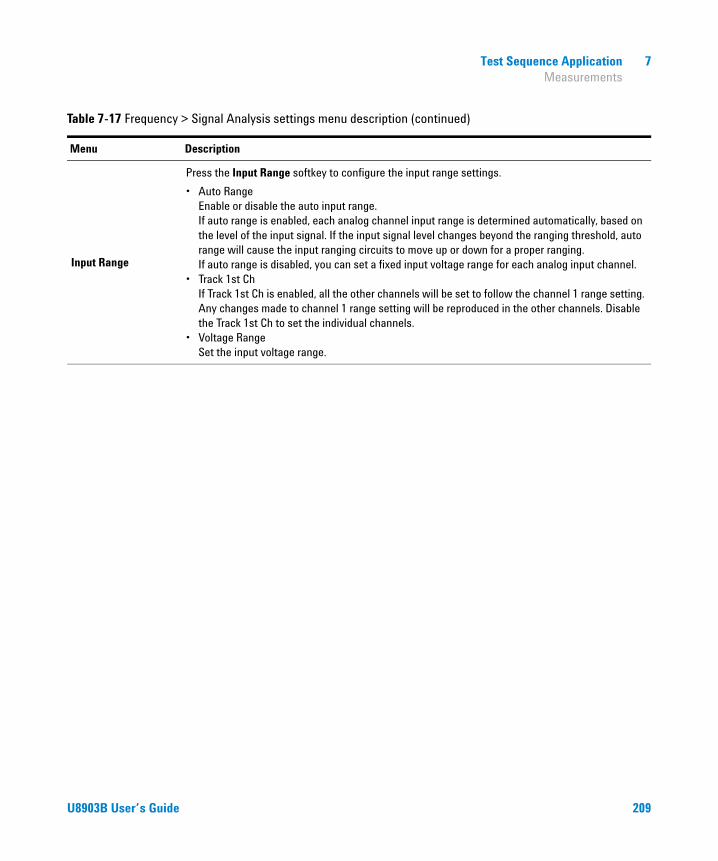
Test Sequence Application 7 Measurements
Input Range
Press the Input Range softkey to configure the input range settings.
• Auto Range Enable or disable the auto input range. If auto range is enabled, each analog channel input range is determined automatically, based on the level of the input signal. If the input signal level changes beyond the ranging threshold, auto range will cause the input ranging circuits to move up or down for a proper ranging. If auto range is disabled, you can set a fixed input voltage range for each analog input channel.
• Track 1st Ch If Track 1st Ch is enabled, all the other channels will be set to follow the channel 1 range setting. Any changes made to channel 1 range setting will be reproduced in the other channels. Disable the Track 1st Ch to set the individual channels.
• Voltage Range Set the input voltage range.
Table 7-17 Frequency > Signal Analysis settings menu description (continued)
Menu Description
U8903B User’s Guide 209
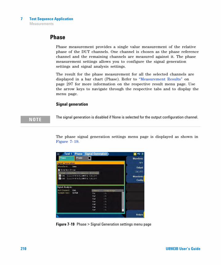
7 Test Sequence Application Measurements
Phase
Phase measurement provides a single value measurement of the relative phase of the DUT channels. One channel is chosen as the phase reference channel and the remaining channels are measured against it. The phase measurement settings allows you to configure the signal generation settings and signal analysis settings.
The result for the phase measurement for all the selected channels are displayed in a bar chart (Phase). Refer to “Measurement Results” on page 297 for more information on the respective result menu page. Use the arrow keys to navigate through the respective tabs and to display the menu page.
Signal generation
The phase signal generation settings menu page is displayed as shown in Figure 7- 19.
Figure 7-19 Phase > Signal Generation settings menu page
NOTE The signal generation is disabled if None is selected for the output configuration channel.
210 U8903B User’s Guide
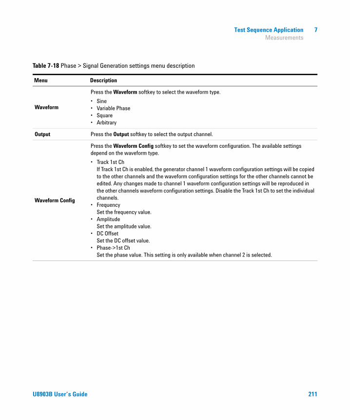
Test Sequence Application 7 Measurements
Table 7-18 Phase > Signal Generation settings menu description
Menu Description
Waveform
Press the Waveform softkey to select the waveform type.
• Sine• Variable Phase• Square• Arbitrary
Output Press the Output softkey to select the output channel.
Waveform Config
Press the Waveform Config softkey to set the waveform configuration. The available settings depend on the waveform type.
• Track 1st Ch If Track 1st Ch is enabled, the generator channel 1 waveform configuration settings will be copied to the other channels and the waveform configuration settings for the other channels cannot be edited. Any changes made to channel 1 waveform configuration settings will be reproduced in the other channels waveform configuration settings. Disable the Track 1st Ch to set the individual channels.
• Frequency Set the frequency value.
• Amplitude Set the amplitude value.
• DC Offset Set the DC offset value.
• Phase->1st Ch Set the phase value. This setting is only available when channel 2 is selected.
U8903B User’s Guide 211

7 Test Sequence Application Measurements
Signal analysis
The phase signal analysis settings menu page is displayed as shown in Figure 7- 20.
Figure 7-20 Phase > Signal Analysis settings menu page
Table 7-19 Phase > Signal Analysis settings menu description
Menu Description
Ref ChannelPress the Ref Channel softkey to set the reference channel number. The phase of each channel is measured against the reference channel. The phase result for the reference channel should always be displayed zero.
212 U8903B User’s Guide
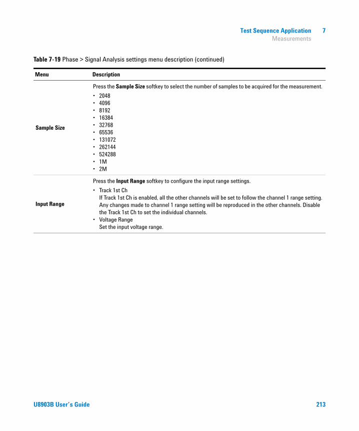
Test Sequence Application 7 Measurements
Sample Size
Press the Sample Size softkey to select the number of samples to be acquired for the measurement.
• 2048• 4096• 8192• 16384• 32768• 65536• 131072• 262144• 524288• 1M• 2M
Input Range
Press the Input Range softkey to configure the input range settings.
• Track 1st Ch If Track 1st Ch is enabled, all the other channels will be set to follow the channel 1 range setting. Any changes made to channel 1 range setting will be reproduced in the other channels. Disable the Track 1st Ch to set the individual channels.
• Voltage Range Set the input voltage range.
Table 7-19 Phase > Signal Analysis settings menu description (continued)
Menu Description
U8903B User’s Guide 213
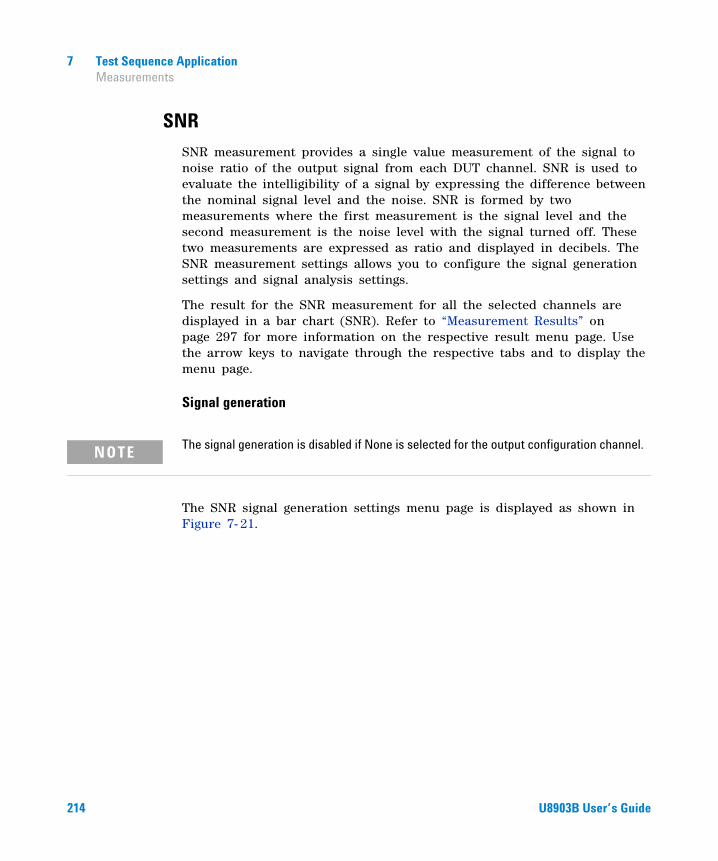
7 Test Sequence Application Measurements
SNR
SNR measurement provides a single value measurement of the signal to noise ratio of the output signal from each DUT channel. SNR is used to evaluate the intelligibility of a signal by expressing the difference between the nominal signal level and the noise. SNR is formed by two measurements where the first measurement is the signal level and the second measurement is the noise level with the signal turned off. These two measurements are expressed as ratio and displayed in decibels. The SNR measurement settings allows you to configure the signal generation settings and signal analysis settings.
The result for the SNR measurement for all the selected channels are displayed in a bar chart (SNR). Refer to “Measurement Results” on page 297 for more information on the respective result menu page. Use the arrow keys to navigate through the respective tabs and to display the menu page.
Signal generation
The SNR signal generation settings menu page is displayed as shown in Figure 7- 21.
NOTE The signal generation is disabled if None is selected for the output configuration channel.
214 U8903B User’s Guide

Test Sequence Application 7 Measurements
Figure 7-21 SNR > Signal Generation settings menu page
Table 7-20 SNR > Signal Generation settings menu description
Menu Description
Waveform
Press the Waveform softkey to select the waveform type.
• Sine• Variable phase• Square• Arbitrary
Output Press the Output softkey to select the output channel.
U8903B User’s Guide 215

7 Test Sequence Application Measurements
Waveform Config
Press the Waveform Config softkey to set the waveform configuration. The available settings depend on the waveform type.
• Track 1st Ch If Track 1st Ch is enabled, the generator channel 1 waveform configuration settings will be copied to the other channels and the waveform configuration settings for the other channels cannot be edited. Any changes made to channel 1 waveform configuration settings will be reproduced in the other channels waveform configuration settings. Disable the Track 1st Ch to set the individual channels.
• Frequency Set the frequency value.
• Amplitude Set the amplitude value.
• DC Offset Set the DC offset value.
• Phase->1st Ch Set the phase value. This setting is only available when channel 2 is selected.
Table 7-20 SNR > Signal Generation settings menu description (continued)
Menu Description
216 U8903B User’s Guide
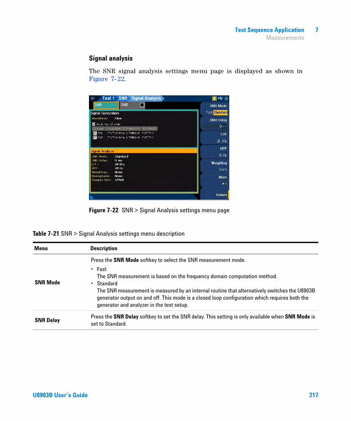
Test Sequence Application 7 Measurements
Signal analysis
The SNR signal analysis settings menu page is displayed as shown in Figure 7- 22.
Figure 7-22 SNR > Signal Analysis settings menu page
Table 7-21 SNR > Signal Analysis settings menu description
Menu Description
SNR Mode
Press the SNR Mode softkey to select the SNR measurement mode.
• Fast The SNR measurement is based on the frequency domain computation method.
• Standard The SNR measurement is measured by an internal routine that alternatively switches the U8903B generator output on and off. This mode is a closed loop configuration which requires both the generator and analyzer in the test setup.
SNR DelayPress the SNR Delay softkey to set the SNR delay. This setting is only available when SNR Mode is set to Standard.
U8903B User’s Guide 217
7 Test Sequence Application Measurements
Freq Lock
Press the Freq Lock softkey to select the searching method for the fundamental frequency. This setting is only available when SNR Mode is set to Fast.
• Auto Selecting Auto will allow the U8903B to search for the fundamental frequency automatically.
• Gen Lock Selecting Gen Lock will allow the U8903B to search for the fundamental frequency based on the generator frequency value of the respective generator channel. This Gen Lock method is only useful if you use the internal audio generator.
• Custom If you have a known input signal, you can define the fundamental frequency value by setting the searching method to Custom and setting the frequency value in Fund Freq.
Fund FreqPress the Fund Freq softkey to set the fundamental frequency value. This setting is only available when SNR Mode is set to Fast and Freq Lock is set to Custom.
Harmonic CntPress the Harmonic Cnt softkey to set the number of harmonic order to be removed. This setting is ony available when SNR Mode is set to Fast.
LPF
Press the Filtering softkey to select the low-pass filter.
• None• 2 kHz• 3 kHz• 5 kHz• 8 kHz• 10 kHz• 15 kHz• 20 kHz• 22 kHz• 30 kHz• 40 kHz• 50 kHz• 80 kHz• Custom
Table 7-21 SNR > Signal Analysis settings menu description (continued)
Menu Description
218 U8903B User’s Guide

Test Sequence Application 7 Measurements
HPF
Press the HPF softkey to select the high-pass filter.
• None• 15 Hz• 20 Hz• 22 Hz• 30 Hz• 50 Hz• 70 Hz• 100 Hz• 200 Hz• 300 Hz• 400 Hz• Custom
Weighting
Press the Weighting softkey to select the weighting filter.
• None• A• CCIR 1k• CCIR 2k• CCITT• C-Message• Custom
Deemphasis
Press the Deemphasis softkey to select the de-emphasis filter.
• None• 50 μs• 75 μs• Custom
Sample Size
Press the Sample Size softkey to select the number of samples to be acquired for the measurement.
• 2048• 4096• 8192• 16384• 32768• 65536• 131072• 262144• 524288• 1M• 2M
Table 7-21 SNR > Signal Analysis settings menu description (continued)
Menu Description
U8903B User’s Guide 219

7 Test Sequence Application Measurements
Input Range
Press the Input Range softkey to configure the input range settings.
• Auto Range Enable or disable the auto input range. If auto range is enabled, each analog channel input range is determined automatically, based on the level of the input signal. If the input signal level changes beyond the ranging threshold, auto range will cause the input ranging circuits to move up or down for a proper ranging. If auto range is disabled, you can set a fixed input voltage range for each analog input channel.
• Track 1st Ch If Track 1st Ch is enabled, all the other channels will be set to follow the channel 1 range setting. Any changes made to channel 1 range setting will be reproduced in the other channels. Disable the Track 1st Ch to set the individual channels.
• Voltage Range Set the input voltage range.
Table 7-21 SNR > Signal Analysis settings menu description (continued)
Menu Description
220 U8903B User’s Guide

Test Sequence Application 7 Measurements
THD+N
THD+N measurement provides a single value measurement of the THD+N (Total Harmonic Distortion with Noise) in the output signal from each DUT channel, as measured at each of the analyzer input. The THD+N measurement settings allows you to configure the signal generation settings and signal analysis settings.
The result for the THD+N measurement for all the selected channels are displayed in a bar chart (SINAD, THD Level, THD Ratio, THD+N Level, and THD+N Ratio). Refer to “Measurement Results” on page 297 for more information on the respective result menu page. Use the arrow keys to navigate through the respective tabs and to display the menu page.
Signal generation
The THD+N signal generation settings menu page is displayed as shown in Figure 7- 23.
Figure 7-23 THD+N > Signal Generation settings menu page
NOTE The signal generation is disabled if None is selected for the output configuration channel.
U8903B User’s Guide 221

7 Test Sequence Application Measurements
Table 7-22 THD+N > Signal Generation settings menu description
Menu Description
Waveform
Press the Waveform softkey to select the waveform type.
• Sine• Variable phase• Square• Arbitrary
Output Press the Output softkey to select the output channel.
Waveform Config
Press the Waveform Config softkey to set the waveform configuration. The available settings depend on the waveform type.
• Track 1st Ch If Track 1st Ch is enabled, the generator channel 1 waveform configuration settings will be copied to the other channels and the waveform configuration settings for the other channels cannot be edited. Any changes made to channel 1 waveform configuration settings will be reproduced in the other channels waveform configuration settings. Disable the Track 1st Ch to set the individual channels.
• Frequency Set the frequency value.
• Amplitude Set the amplitude value.
• DC Offset Set the DC offset value.
• Phase->1st Ch Set the phase value. This setting is only available when channel 2 is selected.
222 U8903B User’s Guide
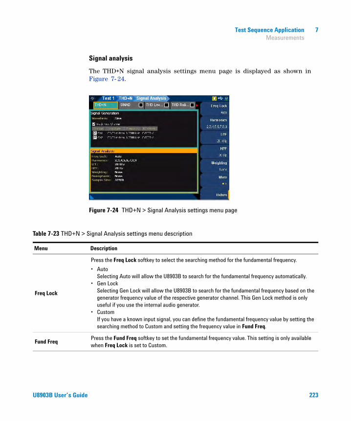
Test Sequence Application 7 Measurements
Signal analysis
The THD+N signal analysis settings menu page is displayed as shown in Figure 7- 24.
Figure 7-24 THD+N > Signal Analysis settings menu page
Table 7-23 THD+N > Signal Analysis settings menu description
Menu Description
Freq Lock
Press the Freq Lock softkey to select the searching method for the fundamental frequency.
• Auto Selecting Auto will allow the U8903B to search for the fundamental frequency automatically.
• Gen Lock Selecting Gen Lock will allow the U8903B to search for the fundamental frequency based on the generator frequency value of the respective generator channel. This Gen Lock method is only useful if you use the internal audio generator.
• Custom If you have a known input signal, you can define the fundamental frequency value by setting the searching method to Custom and setting the frequency value in Fund Freq.
Fund FreqPress the Fund Freq softkey to set the fundamental frequency value. This setting is only available when Freq Lock is set to Custom.
U8903B User’s Guide 223

7 Test Sequence Application Measurements
Harmonics
Press the Harmonics softkey to select the harmonics count to be used in the THD ratio and THD level results.
• All• 2 to 9
LPF
Press the LPF softkey to select the low-pass filter.
• None• 2 kHz• 3 kHz• 5 kHz• 8 kHz• 10 kHz• 15 kHz• 20 kHz• 22 kHz• 30 kHz• 40 kHz• 50 kHz• 80 kHz• Custom
HPF
Press the HPF softkey to select the high-pass filter.
• None• 15 Hz• 20 Hz• 22 Hz• 30 Hz• 50 Hz• 70 Hz• 100 Hz• 200 Hz• 300 Hz• 400 Hz• Custom
Table 7-23 THD+N > Signal Analysis settings menu description (continued)
Menu Description
224 U8903B User’s Guide

Test Sequence Application 7 Measurements
Weighting
Press the Weighting softkey to select the weighting filter.
• None• A• CCIR 1k• CCIR 2k• CCITT• C-Message• Custom
Deemphasis
Press the Deemphasis softkey to select the de-emphasis filter.
• None• 50 μs• 75 μs• Custom
Sample Size
Press the Sample Size softkey to select the number of samples to be acquired for the measurement.
• 2048• 4096• 8192• 16384• 32768• 65536• 131072• 262144• 524288• 1M• 2M
Input Range
Press the Input Range softkey to configure the input range settings.
• Auto Range Enable or disable the auto input range. If auto range is enabled, each analog channel input range is determined automatically, based on the level of the input signal. If the input signal level changes beyond the ranging threshold, auto range will cause the input ranging circuits to move up or down for a proper ranging. If auto range is disabled, you can set a fixed input voltage range for each analog input channel.
• Track 1st Ch If Track 1st Ch is enabled, all the other channels will be set to follow the channel 1 range setting. Any changes made to channel 1 range setting will be reproduced in the other channels. Disable the Track 1st Ch to set the individual channels.
• Voltage Range Set the input voltage range.
Table 7-23 THD+N > Signal Analysis settings menu description (continued)
Menu Description
U8903B User’s Guide 225
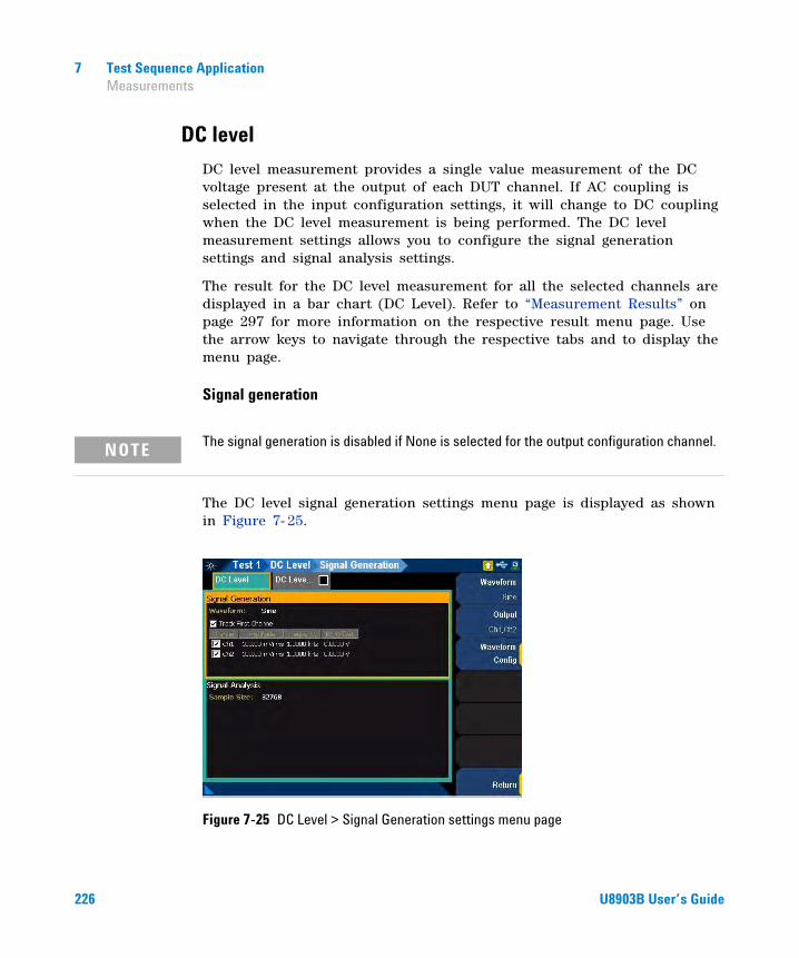
7 Test Sequence Application Measurements
DC level
DC level measurement provides a single value measurement of the DC voltage present at the output of each DUT channel. If AC coupling is selected in the input configuration settings, it will change to DC coupling when the DC level measurement is being performed. The DC level measurement settings allows you to configure the signal generation settings and signal analysis settings.
The result for the DC level measurement for all the selected channels are displayed in a bar chart (DC Level). Refer to “Measurement Results” on page 297 for more information on the respective result menu page. Use the arrow keys to navigate through the respective tabs and to display the menu page.
Signal generation
The DC level signal generation settings menu page is displayed as shown in Figure 7- 25.
Figure 7-25 DC Level > Signal Generation settings menu page
NOTE The signal generation is disabled if None is selected for the output configuration channel.
226 U8903B User’s Guide

Test Sequence Application 7 Measurements
Table 7-24 DC Level > Signal Generation settings menu description
Menu Description
WaveformPress the Waveform softkey to select the waveform type.
• Sine• Arbitrary
Output Press the Output softkey to select the output channel.
Waveform Config
Press the Waveform Config softkey to set the waveform configuration. The available settings depend on the waveform type.
• Track 1st Ch If Track 1st Ch is enabled, the generator channel 1 waveform configuration settings will be copied to the other channels and the waveform configuration settings for the other channels cannot be edited. Any changes made to channel 1 waveform configuration settings will be reproduced in the other channels waveform configuration settings. Disable the Track 1st Ch to set the individual channels.
• Frequency Set the frequency value.
• Amplitude Set the amplitude value.
• DC Offset Set the DC offset value.
U8903B User’s Guide 227
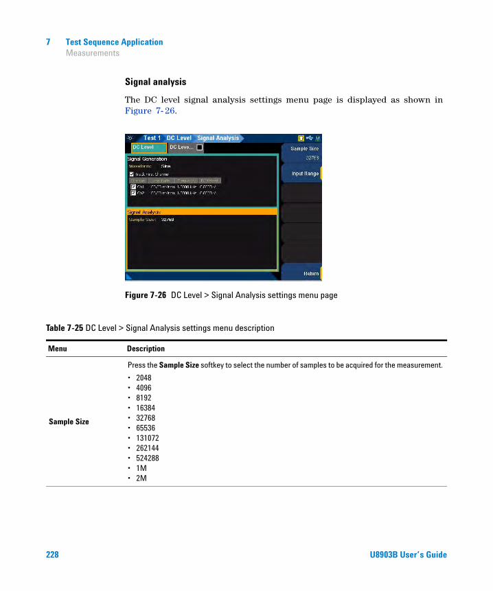
7 Test Sequence Application Measurements
Signal analysis
The DC level signal analysis settings menu page is displayed as shown in Figure 7- 26.
Figure 7-26 DC Level > Signal Analysis settings menu page
Table 7-25 DC Level > Signal Analysis settings menu description
Menu Description
Sample Size
Press the Sample Size softkey to select the number of samples to be acquired for the measurement.
• 2048• 4096• 8192• 16384• 32768• 65536• 131072• 262144• 524288• 1M• 2M
228 U8903B User’s Guide

Test Sequence Application 7 Measurements
Input Range
Press the Input Range softkey to configure the input range settings.
• Auto Range Enable or disable the auto input range. If auto range is enabled, each analog channel input range is determined automatically, based on the level of the input signal. If the input signal level changes beyond the ranging threshold, auto range will cause the input ranging circuits to move up or down for a proper ranging. If auto range is disabled, you can set a fixed input voltage range for each analog input channel.
• Track 1st Ch If Track 1st Ch is enabled, all the other channels will be set to follow the channel 1 range setting. Any changes made to channel 1 range setting will be reproduced in the other channels. Disable the Track 1st Ch to set the individual channels.
• Voltage Range Set the input voltage range.
Table 7-25 DC Level > Signal Analysis settings menu description (continued)
Menu Description
U8903B User’s Guide 229

7 Test Sequence Application Measurements
Crosstalk
Crosstalk is the unwanted leakage or bleed of a signal from one or more channels to other channels in a DUT. Crosstalk measurement provides the measurement of the crosstalk into the unstimulated DUT channel(s) when one channel is stimulated.
The generator will output the test signal to the DUT on the selected driven channel. The crosstalk in each of the remaining channels is then measured. The crosstalk measurement settings allows you to configure the signal generation settings and signal analysis settings.
The crosstalk measured in each channels are displayed in a bar chart (Crosstalk). Refer to “Measurement Results” on page 297 for more information on the respective result menu page. Use the arrow keys to navigate through the respective tabs and to display the menu page.
Signal generation
The crosstalk signal generation settings menu page is displayed as shown in Figure 7- 27.
Figure 7-27 Crosstalk > Signal Generation settings menu page
NOTE The signal generation is disabled if None is selected for the output configuration channel.
230 U8903B User’s Guide

Test Sequence Application 7 Measurements
Table 7-26 Crosstalk > Signal Generation settings menu description
Menu Description
WaveformPress the Waveform softkey to select the waveform type.
• Sine• Arbitrary
Output Press the Output softkey to select the output channel.
Waveform Config
Press the Waveform Config softkey to set the waveform configuration. The available settings depend on the waveform type.
• Track 1st Ch If Track 1st Ch is enabled, the generator channel 1 waveform configuration settings will be copied to the other channels and the waveform configuration settings for the other channels cannot be edited. Any changes made to channel 1 waveform configuration settings will be reproduced in the other channels waveform configuration settings. Disable the Track 1st Ch to set the individual channels.
• Frequency Set the frequency value.
• Amplitude Set the amplitude value.
• DC Offset Set the DC offset value.
U8903B User’s Guide 231

7 Test Sequence Application Measurements
Signal analysis
The crosstalk signal analysis settings menu page is displayed as shown in Figure 7- 28.
Figure 7-28 Crosstalk > Signal Analysis settings menu page
Table 7-27 Crosstalk > Signal Analysis settings menu description
Menu Description
Driven Ch Press the Driver Ch softkey to select the driven channel number from the generator.
Freq Lock
Press the Freq Lock softkey to select the searching method for the fundamental frequency.
• Auto Selecting Auto will allow the U8903B to search for the fundamental frequency automatically.
• Gen Lock Selecting Gen Lock will allow the U8903B to use the driven channel frequency value. You can select the generator channel by setting the Driven Ch. This Gen Lock method is only useful if you use the internal audio generator.
• Custom If you have a known input signal, you can define the fundamental frequency value by setting the searching method to Custom and setting the frequency value in Fund Freq.
Fund FreqPress the Fund Freq softkey to set the fundamental frequency value. This setting is only available when Freq Lock is set to Custom.
232 U8903B User’s Guide
Test Sequence Application 7 Measurements
Sample Size
Press the Sample Size softkey to select the number of samples to be acquired for the measurement.
• 2048• 4096• 8192• 16384• 32768• 65536• 131072• 262144• 524288• 1M• 2M
Input Range
Press the Input Range softkey to configure the input range settings.
• Auto Range Enable or disable the auto input range. If auto range is enabled, each analog channel input range is determined automatically, based on the level of the input signal. If the input signal level changes beyond the ranging threshold, auto range will cause the input ranging circuits to move up or down for a proper ranging. If auto range is disabled, you can set a fixed input voltage range for each analog input channel.
• Track 1st Ch If Track 1st Ch is enabled, all the other channels will be set to follow the channel 1 range setting. Any changes made to channel 1 range setting will be reproduced in the other channels. Disable the Track 1st Ch to set the individual channels.
• Voltage Range Set the input voltage range.
Table 7-27 Crosstalk > Signal Analysis settings menu description (continued)
Menu Description
U8903B User’s Guide 233

7 Test Sequence Application Measurements
SMPTE IMD
SMPTE IMD measurement provides a single value measurement of the IMD ratio in the output signal from each DUT channel using the SMPTE method. The SMPTE IMD measurement settings allows you to configure the signal generation settings and signal analysis settings.
The result for the SMPTE ratio measurement for all the selected channels are displayed in a bar chart (SMPTE Ratio). Refer to “Measurement Results” on page 297 for more information on the respective result menu page. Use the arrow keys to navigate through the respective tabs and to display the menu page.
Signal generation
The SMPTE IMD signal generation settings menu page is displayed as shown in Figure 7- 29.
NOTE This measurement requires a closed loop configuration in which both the generator and the analyzer are used in the test setup. If None is selected for the output configuration channel, this measurement is unavailable.
NOTE The signal generation is disabled if None is selected for the output configuration channel.
234 U8903B User’s Guide

Test Sequence Application 7 Measurements
Figure 7-29 SMPTE IMD > Signal Generation settings menu page
Table 7-28 SMPTE IMD > Signal Generation settings menu description
Menu Description
Waveform
Press the Waveform softkey to select the waveform type.
• SMPTE 1:1• SMPTE 4:1• SMPTE 10:1
Output Press the Output softkey to select the output channel.
U8903B User’s Guide 235

7 Test Sequence Application Measurements
Signal analysis
The SMPTE IMD signal analysis settings menu page is displayed as shown in Figure 7- 30.
Figure 7-30 SMPTE IMD > Signal Analysis settings menu page
Waveform Config
Press the Waveform Config softkey to set the waveform configuration. The available settings depend on the waveform type.
• Track 1st Ch If Track 1st Ch is enabled, the generator channel 1 waveform configuration settings will be copied to the other channels and the waveform configuration settings for the other channels cannot be edited. Any changes made to channel 1 waveform configuration settings will be reproduced in the other channels waveform configuration settings. Disable the Track 1st Ch to set the individual channels.
• Upper Freq Set the upper frequency value.
• Lower Freq Set the lower frequency value.
• Amplitude Set the amplitude value.
• DC Offset Set the DC offset value.
Table 7-28 SMPTE IMD > Signal Generation settings menu description (continued)
Menu Description
236 U8903B User’s Guide
Test Sequence Application 7 Measurements
Table 7-29 SMPTE IMD > Signal Analysis settings menu description
Menu Description
Freq Lock
Press the Freq Lock softkey to select the searching method for the upper and lower frequencies.
• Gen Lock Selecting Gen Lock will allow the U8903B to search for the upper and lower frequencies of the input signal based on the upper and lower frequencies of the respective generator channel. This Gen Lock method is only useful if you use the internal audio generator.
• Custom If you have a known input signal, you can define the upper and lower frequency values by setting the searching method to Custom and setting the frequency value in Upper Freq and Lower Freq.
Upper FreqPress the Upper Freq softkey to set the upper fundamental frequency value. This setting is only available when Freq Lock is set to Custom.
Lower FreqPress the Lower Freq softkey to set the lower fundamental frequency value. This setting is only available when Freq Lock is set to Custom.
Sample Size
Press the Sample Size softkey to select the number of samples to be acquired for the measurement.
• 2048• 4096• 8192• 16384• 32768• 65536• 131072• 262144• 524288• 1M• 2M
U8903B User’s Guide 237

7 Test Sequence Application Measurements
Input Range
Press the Input Range softkey to configure the input range settings.
• Auto Range Enable or disable the auto input range. If auto range is enabled, each analog channel input range is determined automatically, based on the level of the input signal. If the input signal level changes beyond the ranging threshold, auto range will cause the input ranging circuits to move up or down for a proper ranging. If auto range is disabled, you can set a fixed input voltage range for each analog input channel.
• Track 1st Ch If Track 1st Ch is enabled, all the other channels will be set to follow the channel 1 range setting. Any changes made to channel 1 range setting will be reproduced in the other channels. Disable the Track 1st Ch to set the individual channels.
• Voltage Range Set the input voltage range.
Table 7-29 SMPTE IMD > Signal Analysis settings menu description (continued)
Menu Description
238 U8903B User’s Guide

Test Sequence Application 7 Measurements
DFD IMD
DFD IMD measurement provides a single value measurement of the IMD ratio in the output signal from each DUT channel using the DFD method. The DFD measurement settings allows you to configure the signal generation settings and signal analysis settings.
The result for the DFD ratio measurement for all the selected channels are displayed in a bar chart (DFD Ratio). Refer to “Measurement Results” on page 297 for more information on the respective result menu page. Use the arrow keys to navigate through the respective tabs and to display the menu page.
Signal generation
The DFD IMD signal generation settings menu page is displayed as shown in Figure 7- 31.
Figure 7-31 DFD IMD > Signal Generation settings menu page
NOTE The signal generation is disabled if None is selected for the output configuration channel.
U8903B User’s Guide 239
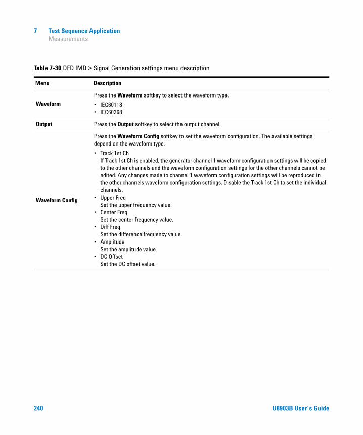
7 Test Sequence Application Measurements
Table 7-30 DFD IMD > Signal Generation settings menu description
Menu Description
WaveformPress the Waveform softkey to select the waveform type.
• IEC60118• IEC60268
Output Press the Output softkey to select the output channel.
Waveform Config
Press the Waveform Config softkey to set the waveform configuration. The available settings depend on the waveform type.
• Track 1st Ch If Track 1st Ch is enabled, the generator channel 1 waveform configuration settings will be copied to the other channels and the waveform configuration settings for the other channels cannot be edited. Any changes made to channel 1 waveform configuration settings will be reproduced in the other channels waveform configuration settings. Disable the Track 1st Ch to set the individual channels.
• Upper Freq Set the upper frequency value.
• Center Freq Set the center frequency value.
• Diff Freq Set the difference frequency value.
• Amplitude Set the amplitude value.
• DC Offset Set the DC offset value.
240 U8903B User’s Guide
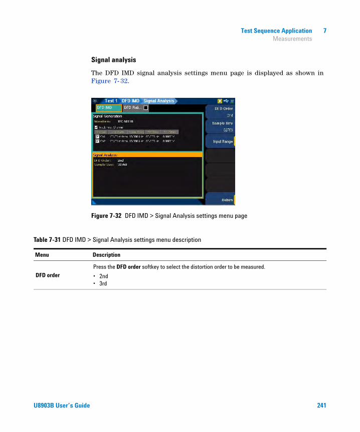
Test Sequence Application 7 Measurements
Signal analysis
The DFD IMD signal analysis settings menu page is displayed as shown in Figure 7- 32.
Figure 7-32 DFD IMD > Signal Analysis settings menu page
Table 7-31 DFD IMD > Signal Analysis settings menu description
Menu Description
DFD orderPress the DFD order softkey to select the distortion order to be measured.
• 2nd• 3rd
U8903B User’s Guide 241
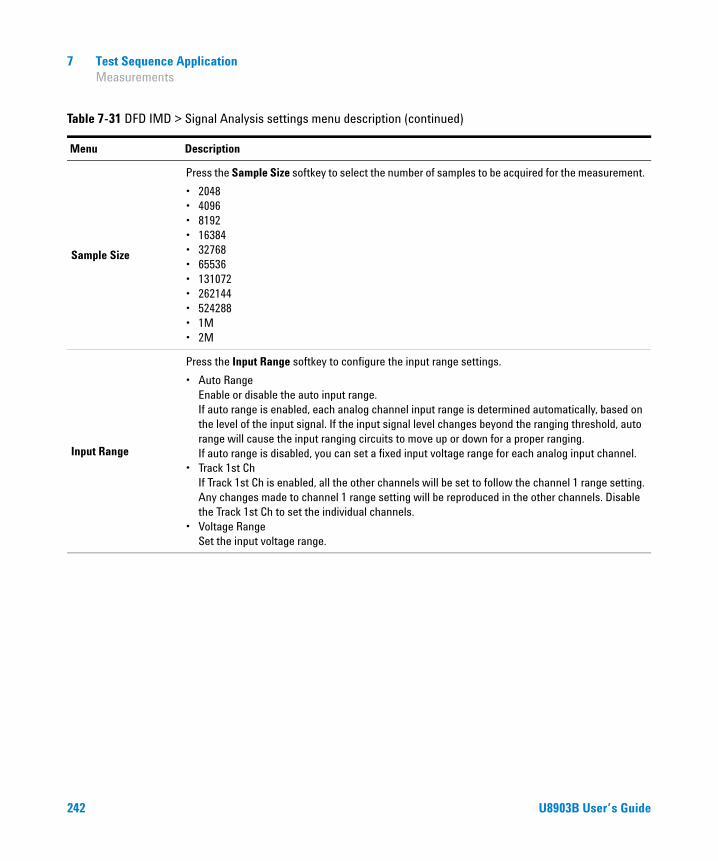
7 Test Sequence Application Measurements
Sample Size
Press the Sample Size softkey to select the number of samples to be acquired for the measurement.
• 2048• 4096• 8192• 16384• 32768• 65536• 131072• 262144• 524288• 1M• 2M
Input Range
Press the Input Range softkey to configure the input range settings.
• Auto Range Enable or disable the auto input range. If auto range is enabled, each analog channel input range is determined automatically, based on the level of the input signal. If the input signal level changes beyond the ranging threshold, auto range will cause the input ranging circuits to move up or down for a proper ranging. If auto range is disabled, you can set a fixed input voltage range for each analog input channel.
• Track 1st Ch If Track 1st Ch is enabled, all the other channels will be set to follow the channel 1 range setting. Any changes made to channel 1 range setting will be reproduced in the other channels. Disable the Track 1st Ch to set the individual channels.
• Voltage Range Set the input voltage range.
Table 7-31 DFD IMD > Signal Analysis settings menu description (continued)
Menu Description
242 U8903B User’s Guide
Test Sequence Application 7 Measurements
Multitone analyzer
Multitone analyzer measurement uses the FFT analysis with a multitone stimulus waveform. The multitone stimulus signal is the combination of two or more sine waveforms. The multitone signal is applied to the DUT, and the DUT output is acquired for measurement. You can create a multitone from the Tones Config menu page in the signal generation settings.
The result for the multitone analyzer measurement for all the selected channels are displayed in a graph (Spectrum, Waveform, Level, and Gain) and in a bar chart (Max Tone Level, Min Tone Level, TD+N Level, TD+N Ratio, and Tone Level). Refer to “Measurement Results” on page 297 for more information on the respective result menu page. Use the arrow keys to navigate through the respective tabs and to display the menu page.
Signal generation
The multitone analyzer signal generation settings menu page is displayed as shown in Figure 7- 33.
NOTE This measurement requires a closed loop configuration in which both the generator and the analyzer are used in the test setup. If None is selected for the output configuration channel, this measurement is unavailable.
NOTE The signal generation is disabled if None is selected for the output configuration channel.
U8903B User’s Guide 243
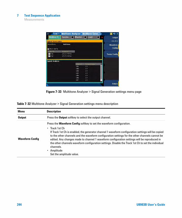
7 Test Sequence Application Measurements
Figure 7-33 Multitone Analyzer > Signal Generation settings menu page
Table 7-32 Multitone Analyzer > Signal Generation settings menu description
Menu Description
Output Press the Output softkey to select the output channel.
Waveform Config
Press the Waveform Config softkey to set the waveform configuration.
• Track 1st Ch If Track 1st Ch is enabled, the generator channel 1 waveform configuration settings will be copied to the other channels and the waveform configuration settings for the other channels cannot be edited. Any changes made to channel 1 waveform configuration settings will be reproduced in the other channels waveform configuration settings. Disable the Track 1st Ch to set the individual channels.
• Amplitude Set the amplitude value.
244 U8903B User’s Guide
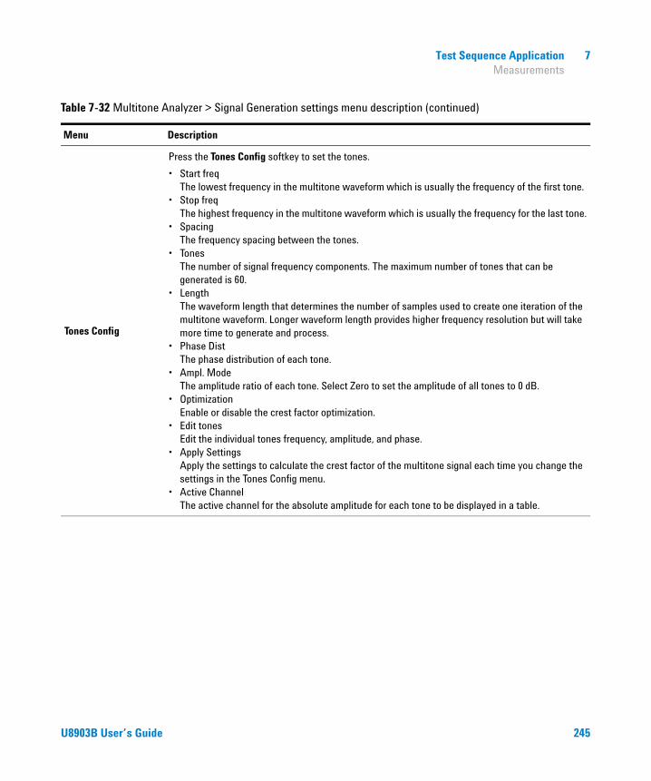
Test Sequence Application 7 Measurements
Tones Config
Press the Tones Config softkey to set the tones.
• Start freq The lowest frequency in the multitone waveform which is usually the frequency of the first tone.
• Stop freq The highest frequency in the multitone waveform which is usually the frequency for the last tone.
• Spacing The frequency spacing between the tones.
• Tones The number of signal frequency components. The maximum number of tones that can be generated is 60.
• Length The waveform length that determines the number of samples used to create one iteration of the multitone waveform. Longer waveform length provides higher frequency resolution but will take more time to generate and process.
• Phase Dist The phase distribution of each tone.
• Ampl. Mode The amplitude ratio of each tone. Select Zero to set the amplitude of all tones to 0 dB.
• Optimization Enable or disable the crest factor optimization.
• Edit tones Edit the individual tones frequency, amplitude, and phase.
• Apply Settings Apply the settings to calculate the crest factor of the multitone signal each time you change the settings in the Tones Config menu.
• Active Channel The active channel for the absolute amplitude for each tone to be displayed in a table.
Table 7-32 Multitone Analyzer > Signal Generation settings menu description (continued)
Menu Description
U8903B User’s Guide 245

7 Test Sequence Application Measurements
Signal analysis
The multitone analyzer signal analysis settings menu page is displayed as shown in Figure 7- 28.
Figure 7-34 Multitone Analyzer > Signal Analysis settings menu page
Table 7-33 Multitone Analyzer > Signal Analysis settings menu description
Menu Description
Input Range
Press the Input Range softkey to configure the input range settings.
• Track 1st Ch If Track 1st Ch is enabled, all the other channels will be set to follow the channel 1 range setting. Any changes made to channel 1 range setting will be reproduced in the other channels. Disable the Track 1st Ch to set the individual channels.
• Voltage Range Set the input voltage range.
246 U8903B User’s Guide

Test Sequence Application 7 Measurements
Stepped frequency sweep
Stepped sweep is an audio testing method where one parameter is swept across a range of values while one or more other parameters are measured. The stepped frequency sweep measurement provides a sine wave stimulus signal that is moved across a range of frequencies in a specified number of points. The DUT output is acquired by the analyzer and the results are displayed on an X-Y graph, with the generator frequency on the X- axis and the measured results from the DUT on the Y- axis (AC Level, Gain, Phase, THD Ratio, THD Level, THD+N Ratio, THD+N Level, and SINAD).
Refer to “Measurement Results” on page 297 for more information on the respective result menu page. Auto ranging is not supported for the phase result. Use the arrow keys to navigate through the respective tabs and to display the menu page.
Signal generation
The stepped frequency sweep signal generation settings menu page is displayed as shown in Figure 7- 35.
NOTE This measurement requires a closed loop configuration in which both the generator and the analyzer are used in the test setup. If None is selected for the output configuration channel, this measurement is unavailable.
NOTE The signal generation is disabled if None is selected for the output configuration channel.
U8903B User’s Guide 247
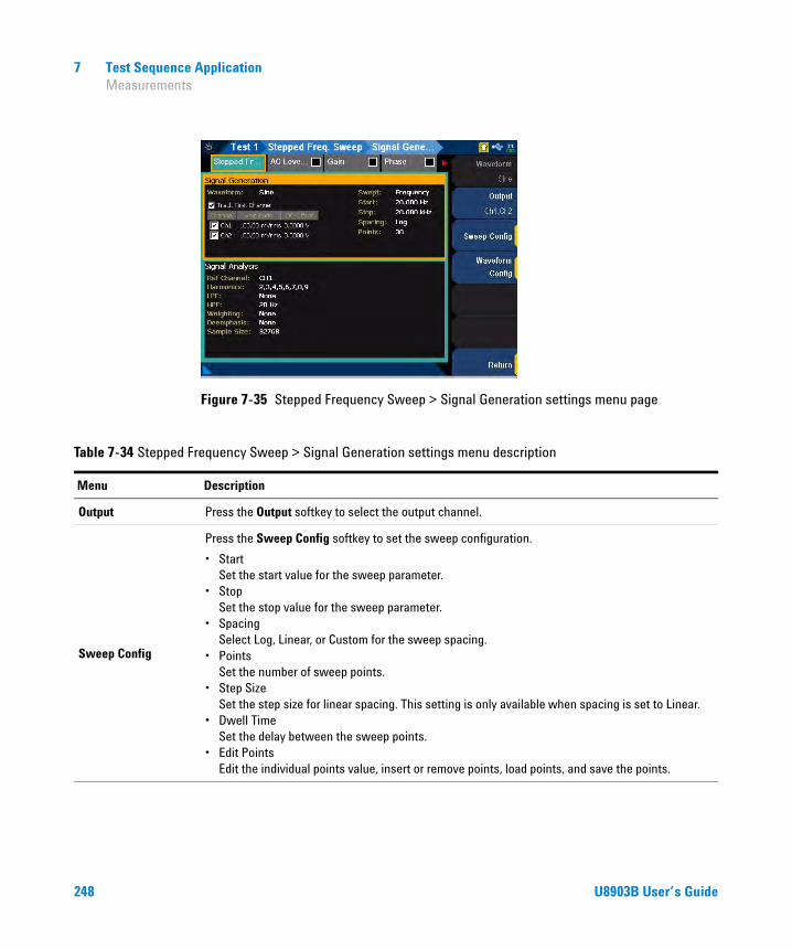
7 Test Sequence Application Measurements
Figure 7-35 Stepped Frequency Sweep > Signal Generation settings menu page
Table 7-34 Stepped Frequency Sweep > Signal Generation settings menu description
Menu Description
Output Press the Output softkey to select the output channel.
Sweep Config
Press the Sweep Config softkey to set the sweep configuration.
• Start Set the start value for the sweep parameter.
• Stop Set the stop value for the sweep parameter.
• Spacing Select Log, Linear, or Custom for the sweep spacing.
• Points Set the number of sweep points.
• Step Size Set the step size for linear spacing. This setting is only available when spacing is set to Linear.
• Dwell Time Set the delay between the sweep points.
• Edit Points Edit the individual points value, insert or remove points, load points, and save the points.
248 U8903B User’s Guide

Test Sequence Application 7 Measurements
Signal analysis
The stepped frequency sweep signal analysis settings menu page is displayed as shown in Figure 7- 36.
Figure 7-36 Stepped Frequency Sweep > Signal Analysis settings menu page
Waveform Config
Press the Waveform Config softkey to set the waveform configuration.
• Track 1st Ch If Track 1st Ch is enabled, the generator channel 1 waveform configuration settings will be copied to the other channels and the waveform configuration settings for the other channels cannot be edited. Any changes made to channel 1 waveform configuration settings will be reproduced in the other channels waveform configuration settings. Disable the Track 1st Ch to set the individual channels.
• Amplitude Set the amplitude value.
• DC Offset Set the DC offset value.
Table 7-34 Stepped Frequency Sweep > Signal Generation settings menu description (continued)
Menu Description
U8903B User’s Guide 249
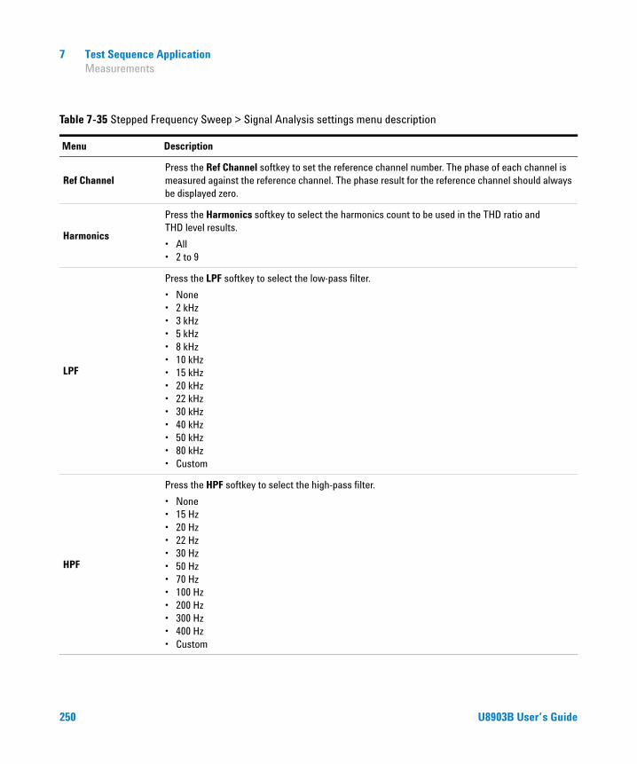
7 Test Sequence Application Measurements
Table 7-35 Stepped Frequency Sweep > Signal Analysis settings menu description
Menu Description
Ref ChannelPress the Ref Channel softkey to set the reference channel number. The phase of each channel is measured against the reference channel. The phase result for the reference channel should always be displayed zero.
Harmonics
Press the Harmonics softkey to select the harmonics count to be used in the THD ratio and THD level results.
• All• 2 to 9
LPF
Press the LPF softkey to select the low-pass filter.
• None• 2 kHz• 3 kHz• 5 kHz• 8 kHz• 10 kHz• 15 kHz• 20 kHz• 22 kHz• 30 kHz• 40 kHz• 50 kHz• 80 kHz• Custom
HPF
Press the HPF softkey to select the high-pass filter.
• None• 15 Hz• 20 Hz• 22 Hz• 30 Hz• 50 Hz• 70 Hz• 100 Hz• 200 Hz• 300 Hz• 400 Hz• Custom
250 U8903B User’s Guide

Test Sequence Application 7 Measurements
Weighting
Press the Weighting softkey to select the weighting filter.
• None• A• CCIR 1k• CCIR 2k• CCITT• C-Message• Custom
Deemphasis
Press the Deemphasis softkey to select the de-emphasis filter.
• None• 50 μs• 75 μs• Custom
Sample Size
Press the Sample Size softkey to select the number of samples to be acquired for the measurement.
• 2048• 4096• 8192• 16384• 32768• 65536• 131072• 262144• 524288• 1M• 2M
Input Range
Press the Input Range softkey to configure the input range settings.
• Auto Range Enable or disable the auto input range. If auto range is enabled, each analog channel input range is determined automatically, based on the level of the input signal. If the input signal level changes beyond the ranging threshold, auto range will cause the input ranging circuits to move up or down for a proper ranging. If auto range is disabled, you can set a fixed input voltage range for each analog input channel.
• Track 1st Ch If Track 1st Ch is enabled, all the other channels will be set to follow the channel 1 range setting. Any changes made to channel 1 range setting will be reproduced in the other channels. Disable the Track 1st Ch to set the individual channels.
• Voltage Range Set the input voltage range.
Table 7-35 Stepped Frequency Sweep > Signal Analysis settings menu description (continued)
Menu Description
U8903B User’s Guide 251

7 Test Sequence Application Measurements
SMPTE frequency sweep
SMPTE frequency sweep measurement will hold one of the two tones at a fixed frequency while the other is swept through a range of frequencies. The results are displayed on an X-Y graph, with the swept frequency on the X- axis and the measured SMPTE ratio on the Y- axis.
Refer to “Measurement Results” on page 297 for more information on the respective result menu page. Use the arrow keys to navigate through the respective tabs and to display the menu page.
Signal generation
The SMPTE frequency sweep signal generation settings menu page is displayed as shown in Figure 7- 37.
Figure 7-37 SMPTE Frequency Sweep > Signal Generation settings menu page
NOTE This measurement requires a closed loop configuration in which both the generator and the analyzer are used in the test setup. If None is selected for the output configuration channel, this measurement is unavailable.
NOTE The signal generation is disabled if None is selected for the output configuration channel.
252 U8903B User’s Guide
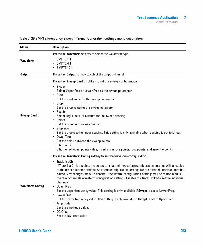
Test Sequence Application 7 Measurements
Table 7-36 SMPTE Frequency Sweep > Signal Generation settings menu description
Menu Description
Waveform
Press the Waveform softkey to select the waveform type.
• SMPTE 1:1• SMPTE 4:1• SMPTE 10:1
Output Press the Output softkey to select the output channel.
Sweep Config
Press the Sweep Config softkey to set the sweep configuration.
• Swept Select Upper Freq or Lower Freq as the sweep parameter.
• Start Set the start value for the sweep parameter.
• Stop Set the stop value for the sweep parameter.
• Spacing Select Log, Linear, or Custom for the sweep spacing.
• Points Set the number of sweep points.
• Step Size Set the step size for linear spacing. This setting is only available when spacing is set to Linear.
• Dwell Time Set the delay between the sweep points.
• Edit Points Edit the individual points value, insert or remove points, load points, and save the points.
Waveform Config
Press the Waveform Config softkey to set the waveform configuration.
• Track 1st Ch If Track 1st Ch is enabled, the generator channel 1 waveform configuration settings will be copied to the other channels and the waveform configuration settings for the other channels cannot be edited. Any changes made to channel 1 waveform configuration settings will be reproduced in the other channels waveform configuration settings. Disable the Track 1st Ch to set the individual channels.
• Upper Freq Set the upper frequency value. This setting is only available if Swept is set to Lower Freq.
• Lower Freq Set the lower frequency value. This setting is only available if Swept is set to Upper Freq.
• Amplitude Set the amplitude value.
• DC Offset Set the DC offset value.
U8903B User’s Guide 253

7 Test Sequence Application Measurements
Signal analysis
The SMPTE frequency sweep signal analysis settings menu page is displayed as shown in Figure 7- 38.
Figure 7-38 SMPTE Frequency Sweep > Signal Analysis settings menu page
Table 7-37 SMPTE Frequency Sweep > Signal Analysis settings menu description
Menu Description
Sample Size
Press the Sample Size softkey to select the number of samples to be acquired for the measurement.
• 2048• 4096• 8192• 16384• 32768• 65536• 131072• 262144• 524288• 1M• 2M
254 U8903B User’s Guide

Test Sequence Application 7 Measurements
Input Range
Press the Input Range softkey to configure the input range settings.
• Auto Range Enable or disable the auto input range. If auto range is enabled, each analog channel input range is determined automatically, based on the level of the input signal. If the input signal level changes beyond the ranging threshold, auto range will cause the input ranging circuits to move up or down for a proper ranging. If auto range is disabled, you can set a fixed input voltage range for each analog input channel.
• Track 1st Ch If Track 1st Ch is enabled, all the other channels will be set to follow the channel 1 range setting. Any changes made to channel 1 range setting will be reproduced in the other channels. Disable the Track 1st Ch to set the individual channels.
• Voltage Range Set the input voltage range.
Table 7-37 SMPTE Frequency Sweep > Signal Analysis settings menu description (continued)
Menu Description
U8903B User’s Guide 255
7 Test Sequence Application Measurements
DFD frequency sweep
DFD frequency sweep measurement will hold one of the two frequencies (IEC60118 upper or difference frequency and IEC60268 center or difference frequency) at a fixed frequency while the other is swept through a range of frequencies. The results are displayed on an X-Y graph, with the swept frequency on the X- axis and the measured DFD ratio on the Y- axis.
Refer to “Measurement Results” on page 297 for more information on the respective result menu page. Use the arrow keys to navigate through the respective tabs and to display the menu page.
Signal generation
The DFD frequency sweep signal generation settings menu page is displayed as shown in Figure 7- 39.
NOTE This measurement requires a closed loop configuration in which both the generator and the analyzer are used in the test setup. If None is selected for the output configuration channel, this measurement is unavailable.
NOTE The signal generation is disabled if None is selected for the output configuration channel.
256 U8903B User’s Guide

Test Sequence Application 7 Measurements
Figure 7-39 DFD Frequency Sweep > Signal Generation settings menu page
Table 7-38 DFD Frequency Sweep > Signal Generation settings menu description
Menu Description
WaveformPress the Waveform softkey to select the waveform type.
• IEC60118• IEC60268
Output Press the Output softkey to select the output channel.
U8903B User’s Guide 257

7 Test Sequence Application Measurements
Sweep Config
Press the Sweep Config softkey to set the sweep configuration.
• Swept Select Upper Freq or Diff Freq as the sweep parameter.
• Start Set the start value for the sweep parameter.
• Stop Set the stop value for the sweep parameter.
• Spacing Select Log, Linear, or Custom for the sweep spacing.
• Points Set the number of sweep points.
• Step Size Set the step size for linear spacing. This setting is only available when spacing is set to Linear.
• Dwell Time Set the delay between the sweep points.
• Edit Points Edit the individual points value, insert or remove points, load points, and save the points.
Waveform Config
Press the Waveform Config softkey to set the waveform configuration.
• Track 1st Ch If Track 1st Ch is enabled, the generator channel 1 waveform configuration settings will be copied to the other channels and the waveform configuration settings for the other channels cannot be edited. Any changes made to channel 1 waveform configuration settings will be reproduced in the other channels waveform configuration settings. Disable the Track 1st Ch to set the individual channels.
• Upper Freq Set the upper frequency value. This setting is only available if Swept is set to Diff Freq.
• Diff Freq Set the difference frequency value. This setting is only available if Swept is set to Upper Freq.
• Amplitude Set the amplitude value.
• DC Offset Set the DC offset value.
Table 7-38 DFD Frequency Sweep > Signal Generation settings menu description (continued)
Menu Description
258 U8903B User’s Guide

Test Sequence Application 7 Measurements
Signal analysis
The DFD frequency sweep signal analysis settings menu page is displayed as shown in Figure 7- 40.
Figure 7-40 DFD Frequency Sweep > Signal Analysis settings menu page
Table 7-39 DFD Frequency Sweep > Signal Analysis settings menu description
Menu Description
DFD orderPress the DFD order softkey to select the distortion product order to be measured.
• 2nd• 3rd
Sample Size
Press the Sample Size softkey to select the number of samples to be acquired for the measurement.
• 2048• 4096• 8192• 16384• 32768• 65536• 131072• 262144• 524288• 1M• 2M
U8903B User’s Guide 259

7 Test Sequence Application Measurements
Input Range
Press the Input Range softkey to configure the input range settings.
• Auto Range Enable or disable the auto input range. If auto range is enabled, each analog channel input range is determined automatically, based on the level of the input signal. If the input signal level changes beyond the ranging threshold, auto range will cause the input ranging circuits to move up or down for a proper ranging. If auto range is disabled, you can set a fixed input voltage range for each analog input channel.
• Track 1st Ch If Track 1st Ch is enabled, all the other channels will be set to follow the channel 1 range setting. Any changes made to channel 1 range setting will be reproduced in the other channels. Disable the Track 1st Ch to set the individual channels.
• Voltage Range Set the input voltage range.
Table 7-39 DFD Frequency Sweep > Signal Analysis settings menu description (continued)
Menu Description
260 U8903B User’s Guide

Test Sequence Application 7 Measurements
Stepped level sweep
Stepped sweep is an audio testing method where one parameter is swept across a range of values while one or more other parameters are measured. The stepped level sweep measurement provides a sine wave stimulus signal that is moved across a range of levels in a specified number of points. The DUT output is acquired by the analyzer and the results are displayed on an X-Y graph, with the generator level on the X- axis and the measured results from the DUT on the Y- axis (AC Level, Gain, THD Ratio, THD Level, THD Ratio Vs Measured Amplitude, THD Level Vs Measured Amplitude, THD+N ratio, THD+N Level, THD+N Ratio Vs Measured Amplitude, THD+N Level Vs Measured Amplitude, and SINAD).
Refer to “Measurement Results” on page 297 for more information on the respective result menu page. Use the arrow keys to navigate through the respective tabs and to display the menu page.
Signal generation
The stepped level sweep signal generation settings menu page is displayed as shown in Figure 7- 41.
NOTE This measurement requires a closed loop configuration in which both the generator and the analyzer are used in the test setup. If None is selected for the output configuration channel, this measurement is unavailable.
NOTE The signal generation is disabled if None is selected for the output configuration channel.
U8903B User’s Guide 261
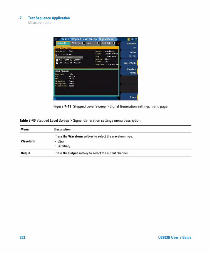
7 Test Sequence Application Measurements
Figure 7-41 Stepped Level Sweep > Signal Generation settings menu page
Table 7-40 Stepped Level Sweep > Signal Generation settings menu description
Menu Description
WaveformPress the Waveform softkey to select the waveform type.
• Sine• Arbitrary
Output Press the Output softkey to select the output channel.
262 U8903B User’s Guide

Test Sequence Application 7 Measurements
Sweep Config
Press the Sweep Config softkey to set the sweep configuration.
• Start Set the start value for the sweep parameter.
• Stop Set the stop value for the sweep parameter.
• Spacing Select Log, Linear, or Custom for the sweep spacing.
• Points Set the number of sweep points.
• Step Size Set the step size for linear spacing. This setting is only available when spacing is set to Linear.
• Dwell Time Set the delay between the sweep points.
• Edit Points Edit the individual points value, insert or remove points, load points, and save the points.
Waveform Config
Press the Waveform Config softkey to set the waveform configuration.
• Track 1st Ch If Track 1st Ch is enabled, the generator channel 1 waveform configuration settings will be copied to the other channels and the waveform configuration settings for the other channels cannot be edited. Any changes made to channel 1 waveform configuration settings will be reproduced in the other channels waveform configuration settings. Disable the Track 1st Ch to set the individual channels.
• Frequency Set the frequency value.
• DC Offset Set the DC offset value.
Table 7-40 Stepped Level Sweep > Signal Generation settings menu description (continued)
Menu Description
U8903B User’s Guide 263

7 Test Sequence Application Measurements
Signal analysis
The stepped level sweep signal analysis settings menu page is displayed as shown in Figure 7- 42.
Figure 7-42 Stepped Level Sweep > Signal Analysis settings menu page
Table 7-41 Stepped Level Sweep > Signal Analysis settings menu description
Menu Description
Freq Lock
Press the Freq Lock softkey to select the searching method for the fundamental frequency.
• Auto Selecting Auto will allow the U8903B to search for the fundamental frequency automatically.
• Gen Lock Selecting Gen Lock will allow the U8903B to search for the fundamental frequency based on the generator frequency value of the respective generator channel. This Gen Lock method is only useful if you use the internal audio generator.
• Custom If you have a known input signal, you can define the fundamental frequency value by setting the searching method to Custom and setting the frequency value in Fund Freq.
Fund FreqPress the Fund Freq softkey to set the fundamental frequency value. This setting is only available when Freq Lock is set to Custom.
264 U8903B User’s Guide

Test Sequence Application 7 Measurements
LPF
Press the LPF softkey to select the low-pass filter.
• None• 2 kHz• 3 kHz• 5 kHz• 8 kHz• 10 kHz• 15 kHz• 20 kHz• 22 kHz• 30 kHz• 40 kHz• 50 kHz• 80 kHz• Custom
HPF
Press the HPF softkey to select the high-pass filter.
• None• 15 Hz• 20 Hz• 22 Hz• 30 Hz• 50 Hz• 70 Hz• 100 Hz• 200 Hz• 300 Hz• 400 Hz• Custom
Weighting
Press the Weighting softkey to select the weighting filter.
• None• A• CCIR 1k• CCIR 2k• CCITT• C-Message• Custom
Table 7-41 Stepped Level Sweep > Signal Analysis settings menu description (continued)
Menu Description
U8903B User’s Guide 265

7 Test Sequence Application Measurements
Deemphasis
Press the Deemphasis softkey to select the de-emphasis filter.
• None• 50 μs• 75 μs• Custom
Sample Size
Press the Sample Size softkey to select the number of samples to be acquired for the measurement.
• 2048• 4096• 8192• 16384• 32768• 65536• 131072• 262144• 524288• 1M• 2M
Input Range
Press the Input Range softkey to configure the input range settings.
• Auto Range Enable or disable the auto input range. If auto range is enabled, each analog channel input range is determined automatically, based on the level of the input signal. If the input signal level changes beyond the ranging threshold, auto range will cause the input ranging circuits to move up or down for a proper ranging. If auto range is disabled, you can set a fixed input voltage range for each analog input channel.
• Track 1st Ch If Track 1st Ch is enabled, all the other channels will be set to follow the channel 1 range setting. Any changes made to channel 1 range setting will be reproduced in the other channels. Disable the Track 1st Ch to set the individual channels.
• Voltage Range Set the input voltage range.
Table 7-41 Stepped Level Sweep > Signal Analysis settings menu description (continued)
Menu Description
266 U8903B User’s Guide

Test Sequence Application 7 Measurements
SMPTE level sweep
SMPTE level sweep measurement will add two tones of different frequencies into a stimulus signal to sweep through a range of levels. The results are displayed on an X-Y graph, with the swept generator level or measured DUT level on the X- axis and the measured SMPTE ratio on the Y- axis.
Refer to “Measurement Results” on page 297 for more information on the respective result menu page. Use the arrow keys to navigate through the respective tabs and to display the menu page.
Signal generation
The SMPTE level sweep signal generation settings menu page is displayed as shown in Figure 7- 43.
Figure 7-43 SMPTE Level Sweep > Signal Generation settings menu page
NOTE This measurement requires a closed loop configuration in which both the generator and the analyzer are used in the test setup. If None is selected for the output configuration channel, this measurement is unavailable.
NOTE The signal generation is disabled if None is selected for the output configuration channel.
U8903B User’s Guide 267

7 Test Sequence Application Measurements
Table 7-42 SMPTE Level Sweep > Signal Generation settings menu description
Menu Description
Waveform
Press the Waveform softkey to select the waveform type.
• SMPTE 1:1• SMPTE 4:1• SMPTE 10:1
Output Press the Output softkey to select the output channel.
Sweep Config
Press the Sweep Config softkey to set the sweep configuration.
• Start Set the start value for the sweep parameter.
• Stop Set the stop value for the sweep parameter.
• Spacing Select Log, Linear, or Custom for the sweep spacing.
• Points Set the number of sweep points.
• Step Size Set the step size for linear spacing. This setting is only available when spacing is set to Linear.
• Dwell Time Set the delay between the sweep points.
• Edit Points Edit the individual points value, insert or remove points, load points, and save the points.
Waveform Config
Press the Waveform Config softkey to set the waveform configuration.
• Track 1st Ch If Track 1st Ch is enabled, the generator channel 1 waveform configuration settings will be copied to the other channels and the waveform configuration settings for the other channels cannot be edited. Any changes made to channel 1 waveform configuration settings will be reproduced in the other channels waveform configuration settings. Disable the Track 1st Ch to set the individual channels.
• Upper Freq Set the upper frequency value.
• Lower Freq Set the lower frequency value.
• DC Offset Set the DC offset value.
268 U8903B User’s Guide

Test Sequence Application 7 Measurements
Signal analysis
The SMPTE level sweep signal analysis settings menu page is displayed as shown in Figure 7- 44.
Figure 7-44 SMPTE Level Sweep > Signal Analysis settings menu page
Table 7-43 SMPTE Level Sweep > Signal Analysis settings menu description
Menu Description
Freq Lock
Press the Freq Lock softkey to select the searching method for the upper and lower frequencies.
• Gen Lock Selecting Gen Lock will allow the U8903B to search for the upper and lower frequencies of the input signal based on the upper and lower frequencies of the respective generator channel. This Gen Lock method is only useful if you use the internal audio generator.
• Custom If you have a known input signal, you can define the upper and lower frequency values by setting the searching method to Custom and setting the frequency value in Upper Freq and Lower Freq.
Upper FreqPress the Upper Freq softkey to set the upper fundamental frequency value. This setting is only available when Freq Lock is set to Custom.
Lower FreqPress the Lower Freq softkey to set the lower fundamental frequency value. This setting is only available when Freq Lock is set to Custom.
U8903B User’s Guide 269

7 Test Sequence Application Measurements
Sample Size
Press the Sample Size softkey to select the number of samples to be acquired for the measurement.
• 2048• 4096• 8192• 16384• 32768• 65536• 131072• 262144• 524288• 1M• 2M
Input Range
Press the Input Range softkey to configure the input range settings.
• Auto Range Enable or disable the auto input range. If auto range is enabled, each analog channel input range is determined automatically, based on the level of the input signal. If the input signal level changes beyond the ranging threshold, auto range will cause the input ranging circuits to move up or down for a proper ranging. If auto range is disabled, you can set a fixed input voltage range for each analog input channel.
• Track 1st Ch If Track 1st Ch is enabled, all the other channels will be set to follow the channel 1 range setting. Any changes made to channel 1 range setting will be reproduced in the other channels. Disable the Track 1st Ch to set the individual channels.
• Voltage Range Set the input voltage range.
Table 7-43 SMPTE Level Sweep > Signal Analysis settings menu description (continued)
Menu Description
270 U8903B User’s Guide
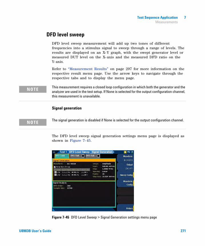
Test Sequence Application 7 Measurements
DFD level sweep
DFD level sweep measurement will add up two tones of different frequencies into a stimulus signal to sweep through a range of levels. The results are displayed on an X-Y graph, with the swept generator level or measured DUT level on the X- axis and the measured DFD ratio on the Y- axis.
Refer to “Measurement Results” on page 297 for more information on the respective result menu page. Use the arrow keys to navigate through the respective tabs and to display the menu page.
Signal generation
The DFD level sweep signal generation settings menu page is displayed as shown in Figure 7- 45.
Figure 7-45 DFD Level Sweep > Signal Generation settings menu page
NOTE This measurement requires a closed loop configuration in which both the generator and the analyzer are used in the test setup. If None is selected for the output configuration channel, this measurement is unavailable.
NOTE The signal generation is disabled if None is selected for the output configuration channel.
U8903B User’s Guide 271

7 Test Sequence Application Measurements
Table 7-44 DFD Level Sweep > Signal Generation settings menu description
Menu Description
WaveformPress the Waveform softkey to select the waveform type.
• IEC60118• IEC60268
Output Press the Output softkey to select the output channel.
Sweep Config
Press the Sweep Config softkey to set the sweep configuration.
• Start Set the start value for the sweep parameter.
• Stop Set the stop value for the sweep parameter.
• Spacing Select Log, Linear, or Custom for the sweep spacing.
• Points Set the number of sweep points.
• Step Size Set the step size for linear spacing. This setting is only available when spacing is set to Linear.
• Dwell Time Set the delay between the sweep points.
• Edit Points Edit the individual points value, insert or remove points, load points, and save the points.
Waveform Config
Press the Waveform Config softkey to set the waveform configuration.
• Track 1st Ch If Track 1st Ch is enabled, the generator channel 1 waveform configuration settings will be copied to the other channels and the waveform configuration settings for the other channels cannot be edited. Any changes made to channel 1 waveform configuration settings will be reproduced in the other channels waveform configuration settings. Disable the Track 1st Ch to set the individual channels.
• Upper Freq Set the upper frequency value.
• Diff Freq Set the difference frequency value.
• DC Offset Set the DC offset value.
272 U8903B User’s Guide

Test Sequence Application 7 Measurements
Signal analysis
The DFD level sweep signal analysis settings menu page is displayed as shown in Figure 7- 46.
Figure 7-46 DFD Level Sweep > Signal Analysis settings menu page
Table 7-45 DFD Level Sweep > Signal Analysis settings menu description
Menu Description
DFD orderPress the DFD order softkey to select the distortion product order to be measured.
• 2nd• 3rd
Sample Size
Press the Sample Size softkey to select the number of samples to be acquired for the measurement.
• 2048• 4096• 8192• 16384• 32768• 65536• 131072• 262144• 524288• 1M• 2M
U8903B User’s Guide 273

7 Test Sequence Application Measurements
Input Range
Press the Input Range softkey to configure the input range settings.
• Auto Range Enable or disable the auto input range. If auto range is enabled, each analog channel input range is determined automatically, based on the level of the input signal. If the input signal level changes beyond the ranging threshold, auto range will cause the input ranging circuits to move up or down for a proper ranging. If auto range is disabled, you can set a fixed input voltage range for each analog input channel.
• Track 1st Ch If Track 1st Ch is enabled, all the other channels will be set to follow the channel 1 range setting. Any changes made to channel 1 range setting will be reproduced in the other channels. Disable the Track 1st Ch to set the individual channels.
• Voltage Range Set the input voltage range.
Table 7-45 DFD Level Sweep > Signal Analysis settings menu description (continued)
Menu Description
274 U8903B User’s Guide

Test Sequence Application 7 Measurements
DC level sweep
DC level sweep measurement sweeps a DC signal across a range of values in a series of points and the DUT output is acquired by the analyzer. The results are displayed on an X-Y graph, with the generator DC level on the X- axis and the measured result on the Y- axis. If AC coupling is selected in the input configuration settings, it will temporary be set to DC coupling while the DC level sweep measurement is performed.
Refer to “Measurement Results” on page 297 for more information on the respective result menu page. Use the arrow keys to navigate through the respective tabs and to display the menu page.
Signal generation
The DC level sweep signal generation settings menu page is displayed as shown in Figure 7- 47.
Figure 7-47 DC Level Sweep > Signal Generation settings menu page
NOTE This measurement requires a closed loop configuration in which both the generator and the analyzer are used in the test setup. If None is selected for the output configuration channel, this measurement is unavailable.
NOTE The signal generation is disabled if None is selected for the output configuration channel.
U8903B User’s Guide 275

7 Test Sequence Application Measurements
Table 7-46 DC Level Sweep > Signal Generation settings menu description
Menu Description
Output Press the Output softkey to select the output channel.
Sweep Config
Press the Sweep Config softkey to set the sweep configuration.
• Start Set the start value for the sweep parameter.
• Stop Set the stop value for the sweep parameter.
• Spacing Select Log, Linear, or Custom for the sweep spacing.
• Points Set the number of sweep points.
• Step Size Set the step size for linear spacing. This setting is only available when spacing is set to Linear.
• Dwell Time Set the delay between the sweep points.
• Edit Points Edit the individual points value, insert or remove points, load points, and save the points.
276 U8903B User’s Guide

Test Sequence Application 7 Measurements
Signal analysis
The DC level sweep signal analysis settings menu page is displayed as shown in Figure 7- 48.
Figure 7-48 DC Level Sweep > Signal Analysis settings menu page
Table 7-47 DC Level Sweep > Signal Analysis settings menu description
Menu Description
LPF
Press the LPF softkey to select the low-pass filter.
• None• 2 kHz• 3 kHz• 5 kHz• 8 kHz• 10 kHz• 15 kHz• 20 kHz• 22 kHz• 30 kHz• 40 kHz• 50 kHz• 80 kHz• Custom
U8903B User’s Guide 277

7 Test Sequence Application Measurements
HPF
Press the HPF softkey to select the high-pass filter.
• None• 15 Hz• 20 Hz• 22 Hz• 30 Hz• 50 Hz• 70 Hz• 100 Hz• 200 Hz• 300 Hz• 400 Hz• Custom
Weighting
Press the Weighting softkey to select the weighting filter.
• None• A• CCIR 1k• CCIR 2k• CCITT• C-Message• Custom
Deemphasis
Press the Deemphasis softkey to select the de-emphasis filter.
• None• 50 μs• 75 μs• Custom
Sample Size
Press the Sample Size softkey to select the number of samples to be acquired for the measurement.
• 2048• 4096• 8192• 16384• 32768• 65536• 131072• 262144• 524288• 1M• 2M
Table 7-47 DC Level Sweep > Signal Analysis settings menu description (continued)
Menu Description
278 U8903B User’s Guide

Test Sequence Application 7 Measurements
Input Range
Press the Input Range softkey to configure the input range settings.
• Auto Range Enable or disable the auto input range. If auto range is enabled, each analog channel input range is determined automatically, based on the level of the input signal. If the input signal level changes beyond the ranging threshold, auto range will cause the input ranging circuits to move up or down for a proper ranging. If auto range is disabled, you can set a fixed input voltage range for each analog input channel.
• Track 1st Ch If Track 1st Ch is enabled, all the other channels will be set to follow the channel 1 range setting. Any changes made to channel 1 range setting will be reproduced in the other channels. Disable the Track 1st Ch to set the individual channels.
• Voltage Range Set the input voltage range.
Table 7-47 DC Level Sweep > Signal Analysis settings menu description (continued)
Menu Description
U8903B User’s Guide 279

7 Test Sequence Application Measurements
RF power sweep
RF power measurement uses an external RF (radio frequency) signal generator to create a RF stimulus signal that is moved across a range of powers in a specified number of points. The DUT output which is in analog audio is acquired by the analyzer and processed for display.
The RF power sweep measurement is typically used for characterizing radio sensitivity by measuring SINAD. SINAD is an audio quality value that is used to specify the RF sensitivity of radio receivers. A higher SINAD value indicates higher quality audio.
Figure 7- 49 shows a general setup for the RF power sweep measurement. A signal generator provides its own modulation and the U8903B controls the signal generator through Agilent 82357B USB/GPIB interface. A receiver such as a two- way radio is connected to the U8903B either by a direct connection or through an acoustic coupler.
Figure 7-49 General setup for the RF power sweep measurement
Set the audio output level of the receiver as required and the signal generator settings to the desired value. The U8903B will automatically adjust the RF power output from the signal generator so that the targeted SINAD is produced at the receiver output. The targeted SINAD value is generally 12 dB for a communications receiver and 23 dB (mono) or 26 dB (stereo) for a broadcast receiver such as a car radio or Hi- Fi tuner.
280 U8903B User’s Guide

Test Sequence Application 7 Measurements
The results are displayed on an X-Y graph, with the RF power parameter on the X- axis and the measured SINAD results on the Y- axis. Refer to “Measurement Results” on page 297 for more information on the respective result menu page. Use the arrow keys to navigate through the respective tabs and to display the menu page.
Signal generation
The RF power sweep signal generation settings menu page is displayed as shown in Figure 7- 50.
Figure 7-50 RF Power Sweep > Signal Generation settings menu page
U8903B User’s Guide 281

7 Test Sequence Application Measurements
Table 7-48 RF Power Sweep > Signal Generation settings menu description
Menu Description
Ext. InstrumentPress the Ext. Instrument softkey to set the signal generator model.
• Agilent E4438C• Other
GPIB address Press the GPIB address softkey to set the GPIB address for the connected signal generator.
Start Power Press the Start Power softkey to set the sweep start RF power.
Stop Power Press the Stop Power softkey to set the sweep stop RF power.
Coarse Step
Press the Coarse Step softkey to set the coarse step size.
The RF power sweep measurement will sweep using the coarse step size first to minimize the time taken. By default, the coarse step is set to 5 dB. The coarse step value cannot be less than the fine step value.
Fine Step
Press the Fine Step softkey to set the fine step size.
The fine step size is used after the first sweep to improve the accuracy of the targeted SINAD measured. By default, the fine step is set to 0.2 dB. The fine step value cannot be more than the coarse step value.
Dwell Time Press the Dwell Time softkey to set the delay between each measured SINAD in seconds.
Init InstrumentPress the Init Instrument softkey to enable or disable the U8903B to send SCPI commands to initialize the connected signal generator.
FM FrequencyPress the FM Frequency softkey to set the RF signal output frequency. This setting is only available if Ext. Instrument is set to Agilent E4438C and the Init Instrument is enabled.
FM DeviationPress the FM Deviation softkey to set the RF signal frequency modulation deviation. This setting is only available if Ext. Instrument is set to Agilent E4438C and the Init Instrument is enabled.
FM RatePress the FM Rate softkey to set the RF signal internal frequency modulation rate. This setting is only available if Ext. Instrument is set to Agilent E4438C and the Init Instrument is enabled.
282 U8903B User’s Guide

Test Sequence Application 7 Measurements
Signal analysis
The RF power sweep signal analysis settings menu page is displayed as shown in Figure 7- 51.
Figure 7-51 RF Power Sweep > Signal Analysis settings menu page
Init SCPIPress the Init SCPI softkey to set the SCPI commands that initialize the connected signal generator. You can set the SCPI command directly or load from a file. This setting is only available if Ext. Instrument is set to Other and the Init Instrument is enabled.
Output Power SCPI
Press the Output Power SCPI softkey to edit the SCPI command that adjusts the RF power of the connected signal generator. The command must be in the following pattern.
Cmds <val>
Cmds is the SCPI command and <val> is the value that will be filled up by the measurement to perform sweep. For example, :POW <val>DBM. This setting is only available if Ext. Instrument is set to Other.
Table 7-48 RF Power Sweep > Signal Generation settings menu description (continued)
Menu Description
U8903B User’s Guide 283

7 Test Sequence Application Measurements
Table 7-49 RF Power Sweep > Signal Analysis settings menu description
Menu Description
Meas Channel Press the Meas Channel softkey to set the measured channel number.
Target SINAD Press the Target SINAD softkey to set the target SINAD value measured from the Meas Channel.
Freq Lock
Press the Freq Lock softkey to select the searching method for the fundamental frequency.
• Auto Selecting Auto will allow the U8903B to search for the fundamental frequency automatically.
• Custom If you have a known input signal, you can define the fundamental frequency value by setting the searching method to Custom and setting the frequency value in Fund Freq.
Fund FreqPress the Fund Freq softkey to set the fundamental frequency value. This setting is only available when Freq Lock is set to Custom.
LPF
Press the LPF softkey to select the low-pass filter.
• None• 2 kHz• 3 kHz• 5 kHz• 8 kHz• 10 kHz• 15 kHz• 20 kHz• 22 kHz• 30 kHz• 40 kHz• 50 kHz• 80 kHz• Custom
284 U8903B User’s Guide

Test Sequence Application 7 Measurements
HPF
Press the HPF softkey to select the high-pass filter.
• None• 15 Hz• 20 Hz• 22 Hz• 30 Hz• 50 Hz• 70 Hz• 100 Hz• 200 Hz• 300 Hz• 400 Hz• Custom
Weighting
Press the Weighting softkey to select the weighting filter.
• None• A• CCIR 1k• CCIR 2k• CCITT• C-Message• Custom
Deemphasis
Press the Deemphasis softkey to select the de-emphasis filter.
• None• 50 μs• 75 μs• Custom
Average PointsPress the Average Points softkey to set the number of measurement readings to be used for the average calculation. This is useful for noisy signals. Applying the average points will smooth out the fluctuations introduced by the noise that causes the inconsistencies in the measurement reading.
Table 7-49 RF Power Sweep > Signal Analysis settings menu description (continued)
Menu Description
U8903B User’s Guide 285
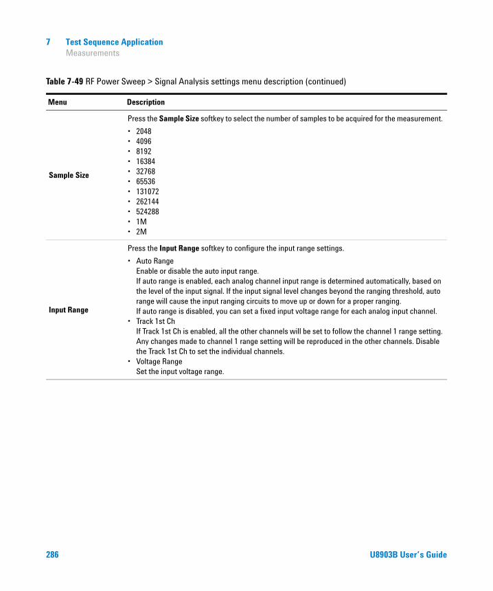
7 Test Sequence Application Measurements
Sample Size
Press the Sample Size softkey to select the number of samples to be acquired for the measurement.
• 2048• 4096• 8192• 16384• 32768• 65536• 131072• 262144• 524288• 1M• 2M
Input Range
Press the Input Range softkey to configure the input range settings.
• Auto Range Enable or disable the auto input range. If auto range is enabled, each analog channel input range is determined automatically, based on the level of the input signal. If the input signal level changes beyond the ranging threshold, auto range will cause the input ranging circuits to move up or down for a proper ranging. If auto range is disabled, you can set a fixed input voltage range for each analog input channel.
• Track 1st Ch If Track 1st Ch is enabled, all the other channels will be set to follow the channel 1 range setting. Any changes made to channel 1 range setting will be reproduced in the other channels. Disable the Track 1st Ch to set the individual channels.
• Voltage Range Set the input voltage range.
Table 7-49 RF Power Sweep > Signal Analysis settings menu description (continued)
Menu Description
286 U8903B User’s Guide
Test Sequence Application 7 Measurements
Measurement recorder
Measurement recorder is a tool that provides a record of a number of measurements versus elapsed time. It is useful to monitor the output of a DUT over an extended period of time. The measurement recorder does not require a specific test signal. It can be used with any audio signal within the input range of the analyzer or with no signal.
The reading rate of the measurement recorder is dependent on the channel count, sample size, and result type. A reading is obtained at the beginning of the measurement and throughout the duration set until the elapsed time.
The results are displayed on an X-Y graph, with the time parameter on the X- axis and the measured results on the Y- axis (AC Level, Gain, Phase, THD+N Ratio, THD+N Level, DC Level, Frequency, and SINAD). Refer to “Measurement Results” on page 297 for more information on the respective result menu page. Use the arrow keys to navigate through the respective tabs and to display the menu page.
Signal generation
The measurement recorder signal generation settings menu page is displayed as shown in Figure 7- 52.
NOTE • Auto ranging is not supported for the phase result.
• DC level result is not available if AC coupling is selected in the output configuration settings.
NOTE The signal generation is disabled if None is selected for the output configuration channel.
U8903B User’s Guide 287

7 Test Sequence Application Measurements
Figure 7-52 Measurement Recorder > Signal Generation settings menu page
Table 7-50 Measurement Recorder > Signal Generation settings menu description
Menu Description
Waveform
Press the Waveform softkey to select the waveform type.
• Sine• Variable Phase• Square• Arbitrary
Output Press the Output softkey to select the output channel.
Waveform Config
Press the Waveform Config softkey to set the waveform configuration.
• Track 1st Ch If Track 1st Ch is enabled, the generator channel 1 waveform configuration settings will be copied to the other channels and the waveform configuration settings for the other channels cannot be edited. Any changes made to channel 1 waveform configuration settings will be reproduced in the other channels waveform configuration settings. Disable the Track 1st Ch to set the individual channels.
• Frequency Set the frequency value.
• Amplitude Set the amplitude value.
• DC Offset Set the DC offset value.
288 U8903B User’s Guide
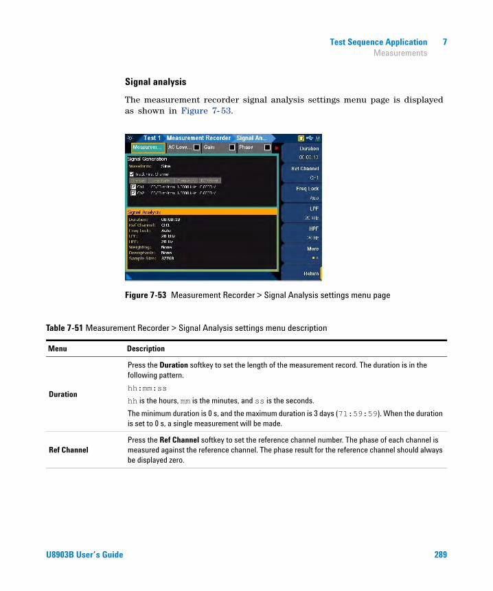
Test Sequence Application 7 Measurements
Signal analysis
The measurement recorder signal analysis settings menu page is displayed as shown in Figure 7- 53.
Figure 7-53 Measurement Recorder > Signal Analysis settings menu page
Table 7-51 Measurement Recorder > Signal Analysis settings menu description
Menu Description
Duration
Press the Duration softkey to set the length of the measurement record. The duration is in the following pattern.
hh:mm:ss
hh is the hours, mm is the minutes, and ss is the seconds.
The minimum duration is 0 s, and the maximum duration is 3 days (71:59:59). When the duration is set to 0 s, a single measurement will be made.
Ref ChannelPress the Ref Channel softkey to set the reference channel number. The phase of each channel is measured against the reference channel. The phase result for the reference channel should always be displayed zero.
U8903B User’s Guide 289
7 Test Sequence Application Measurements
Freq Lock
Press the Freq Lock softkey to select the searching method for the fundamental frequency.
• Auto Selecting Auto will allow the U8903B to search for the fundamental frequency automatically.
• Gen Lock Selecting Gen Lock will allow the U8903B to search for the fundamental frequency based on the generator frequency value of the respective generator channel. This Gen Lock method is only useful if you use the internal audio generator.
• Custom If you have a known input signal, you can define the fundamental frequency value by setting the searching method to Custom and setting the frequency value in Fund Freq.
Fund FreqPress the Fund Freq softkey to set the fundamental frequency value. This setting is only available when Freq Lock is set to Custom.
LPF
Press the LPF softkey to select the low-pass filter.
• None• 2 kHz• 3 kHz• 5 kHz• 8 kHz• 10 kHz• 15 kHz• 20 kHz• 22 kHz• 30 kHz• 40 kHz• 50 kHz• 80 kHz• Custom
Table 7-51 Measurement Recorder > Signal Analysis settings menu description (continued)
Menu Description
290 U8903B User’s Guide

Test Sequence Application 7 Measurements
HPF
Press the HPF softkey to select the high-pass filter.
• None• 15 Hz• 20 Hz• 22 Hz• 30 Hz• 50 Hz• 70 Hz• 100 Hz• 200 Hz• 300 Hz• 400 Hz• Custom
Weighting
Press the Weighting softkey to select the weighting filter.
• None• A• CCIR 1k• CCIR 2k• CCITT• C-Message• Custom
Deemphasis
Press the Deemphasis softkey to select the de-emphasis filter.
• None• 50 μs• 75 μs• Custom
Sample Size
Press the Sample Size softkey to select the number of samples to be acquired for the measurement.
• 2048• 4096• 8192• 16384• 32768• 65536• 131072• 262144• 524288• 1M• 2M
Table 7-51 Measurement Recorder > Signal Analysis settings menu description (continued)
Menu Description
U8903B User’s Guide 291
7 Test Sequence Application Measurements
Input Range
Press the Input Range softkey to configure the input range settings.
• Auto Range Enable or disable the auto input range. If auto range is enabled, each analog channel input range is determined automatically, based on the level of the input signal. If the input signal level changes beyond the ranging threshold, auto range will cause the input ranging circuits to move up or down for a proper ranging. If auto range is disabled, you can set a fixed input voltage range for each analog input channel.
• Track 1st Ch If Track 1st Ch is enabled, all the other channels will be set to follow the channel 1 range setting. Any changes made to channel 1 range setting will be reproduced in the other channels. Disable the Track 1st Ch to set the individual channels.
• Voltage Range Set the input voltage range.
Table 7-51 Measurement Recorder > Signal Analysis settings menu description (continued)
Menu Description
292 U8903B User’s Guide

Test Sequence Application 7 Measurements
POLQA
Perceptual Objective Listening Quality Assessment (POLQA) is the next generation voice quality testing technology for fixed, mobile, and IP- based networks. POLQA was standardized by the ITU- T (International Telecommunication Union) as the new Recommendation P.863 and can be applied for voice quality analysis of high definition voice, 3G, and 4G/LTE networks. POLQA is licensed by OPTICOM GmbH.
POLQA provides significantly improved benchmark accuracy for 3G and strong support for testing of most recent technologies such as Unified Communications, Next Gen Networks, and 4G/LTE compared to PESQ/P8.862 that was originally released in the year 2001.
POLQA measurement working model is to predict speech quality by analysing digital speech signal. The objectives measures should be as close as possible to the subjective quality scores as if it would be obtained from subjective listening tests. Typically, POLQA measurement uses real speech as a test stimulus to assess the quality and performance of telephony networks. POLQA measurement is the successor to PESQ/P8.862 measurement.
NOTE POLQA measurement is only available with N3432A. Refer to “U8903B Options” on page 5 for more information.
NOTE Perceptual Objective Listening Quality Analysis (POLQA) according to ITU-T Recommendation P. 863 included in this product is protected by copyright and by European, US and other International patents and patent applications and is provided under license from OPTICOM Dipl.-Ing. M. Keyhl GmbH, Erlangen, Germany, 2011 - www.opticom.de.
POLQA® is a registered trademark of OPTICOM GmbH. Used by permission.
© 2011 by the POLQA Coalition of OPTICOM GmbH, Germany - SwissQual AG, Switzerland - KPN, The Netherlands - TNO, The Netherlands.
Copying, modifying, translating, reverse engineering or decompiling the POLQA Software is prohibited. Acknowledgement of the rights in the POLQA software shall not be removed from the POLQA software or any installation of it.
For further information please refer to www.polqa.info.
U8903B User’s Guide 293

7 Test Sequence Application Measurements
The result for the POLQA measurement for all the selected channels are displayed in a graph (Surface) and in a bar chart (MOS- LQO, Levels, and Delay). Refer to “Measurement Results” on page 297 for more information on the respective result menu page. Use the arrow keys to navigate through the respective tabs and to display the menu page.
Signal generation and analysis
The POLQA signal generation and analysis settings menu page is displayed as shown in Figure 7- 54.
Figure 7-54 POLQA > Signal Generation and Analysis settings menu page
Table 7-52 POLQA > Signal Generation and Analysis settings menu description
Menu Description
Analysis Mode
Press the Analysis Mode sotkey to select the POLQA analysis mode.
• Basic Load the reference and degraded wave files, and perform analysis automatically.
• Advanced Perform wave file playback and recording, and analysis automatically.
Playback File PathPress the Playback File Path softkey to select the playback wave file source to be used. Refer to “Recall” on page 62 for more information on the Recall menu page. This setting is only available when Analysis Mode is set to Basic.
294 U8903B User’s Guide

Test Sequence Application 7 Measurements
Degraded File PathPress the Degraded File Path softkey to select the degraded wave file source to be used. Refer to “Recall” on page 62 for more information on the Recall menu page. This setting is only available when Analysis Mode is set to Basic.
Reference Source
Press the Reference Source sotkey to set the reference source configuration. This setting is only available when Analysis Mode is set to Advanced.
• Source Select file or a generator channel as the reference source.
• Playback File Path Select the playback wave file source to be used. This setting is only available when Source is set to File.
• Playback Ch Select the generator channel to play the reference file or waveform.
• Recording Ch Select the playback file or an analyzer channel as the reference file.
• Rec Duration Set the recording duration used to record from an analyzer channel. This setting is only available when Recording Ch is set to analyzer channel.
• Delay Set the delay in seconds before a recording is performed after the generator is turned on. This setting is only available when Recording Ch is set to analyzer channel.
• Save to File Enable or disable automatically save the reference file. This setting is only available when Recording Ch is set to an analyzer channel.
• Save File Path Set the location to save the reference file. This setting is only available when Save to File is enabled.
Table 7-52 POLQA > Signal Generation and Analysis settings menu description (continued)
Menu Description
U8903B User’s Guide 295
7 Test Sequence Application Measurements
Degraded Source
Press the Degraded Source sotkey to set the degraded source configuration. This setting is only available when Analysis Mode is set to Advanced.
• Source Select file or an analyzer channel as the degraded source.
• Save to File Enable or disable automatically save the degraded wave file. This setting is only available when Source is set to an analyzer channel.
• Degraded File Path Select the degraded wave file source to be used. This setting is only available when Source is set to File.
• Rec Duration Set the recording duration used to record the degraded wave file. This setting is only available when Source is set to an analyzer channel.
• Delay Set the delay in seconds before a recording is performed after the generator is turned on. This setting is only available when Source is set to an analyzer channel.
POLQA Config
Press the POLQA Config sotkey to set the POLQA measurement configuration.
• Bandwidth Select the analysis bandwidth.• SWB
Super wideband sample rate: 48 kHz• NB
Narrow band sample rate: 8 kHz, 16 kHz, 48 kHz• Auto Lvl Align
Enable or disable the automatic level alignment.• Auto Fs
Enable or disable the resampling of the input signals to a suitable sample rate. The sample rates for all narrow band mode and super wideband input files will be resampled to 8 kHz and 48 kHz respectively.
Show/Hide POLQA License
Press the Show/Hide POLQA License softkey to show or hide the POLQA license information.
Table 7-52 POLQA > Signal Generation and Analysis settings menu description (continued)
Menu Description
296 U8903B User’s Guide

Test Sequence Application 7 Measurement Results
Measurement Results
The test sequence application allows you to display the measurement results in a bar chart or graph.
Bar chart
An example of the bar chart result menu page is displayed as shown in Figure 7- 55.
Figure 7-55 AC Level > Settings > Result (AC level) menu page
Table 7-53 TSA > Project > Test > Measurement > Settings > Result (bar chart) menu description
Menu Description
Status Press the Status softkey to enable or disable the selected result tab.
Add Result Press the Add Result softkey to add a new result tab to the measurement.
Delete Result Press the Delete Result softkey to delete the selected result tab from the measurement.
Save DataPress the Save Data softkey to save the selected result data to a CSV file format in the internal storage or external USB flash storage. Refer to “Save” on page 61 for the Save menu page.
U8903B User’s Guide 297

7 Test Sequence Application Measurement Results
Edit Limits
Press the Edit Limits softkey to configure the limits settings.
• Track 1st If Track 1st trace is enabled, the channel 1 limits settings will be copied to the other channels and the limits settings for the other channels cannot be edited. Any changes made to the channel 1 limits settings will be reproduced in the other channels limits settings. Disable the Track 1st trace to set the individual channels limits.
• Lower Limit Enable or disable the lower limit.
• Upper Limit Enable or disable the upper limit.
• Lower Limit Set the lower limit value.
• Upper Limit Set the upper limit value.
Graph Properties
Press the Graph Properties softkey to set the graph properties.
• Title Edit the bar chart title.
• X-axis• Auto Scale
Enable or disable the X-axis autoscale.• Unit
Select the X-axis unit type.• Left
Set the X-axis left edge value. This setting is only available when Auto Scale is disabled.• Right
Set the X-axis right edge value. This setting is only available when Auto Scale is disabled.
Table 7-53 TSA > Project > Test > Measurement > Settings > Result (bar chart) menu description (continued)
Menu Description
298 U8903B User’s Guide

Test Sequence Application 7 Measurement Results
Graph
An example of the graph result menu page is displayed as shown in Figure 7- 56.
Figure 7-56 Multitone Analyzer > Settings > Result (Spectrum) menu page
Table 7-54 TSA > Project > Test > Measurement > Settings > Result (graph) menu description
Menu Description
Status Press the Status softkey to enable or disable the selected result tab.
Add Result Press the Add Result softkey to add a new result tab to the measurement.
Delete Result Press the Delete Result softkey to delete the selected result tab from the measurement.
Save DataPress the Save Data softkey to save the selected result data to a CSV file format in the internal storage or external USB flash storage. Refer to “Save” on page 61 for the Save menu page.
U8903B User’s Guide 299

7 Test Sequence Application Measurement Results
Edit Limits
Press the Edit Limits softkey to configure the limits settings.
• Trace Select the trace channel number or the trace type (POLQA measurement)
• Limit Type Select Upper or Lower as the limit type.
• Track 1st If Track 1st trace is enabled, the channel 1 limits settings will be copied to the other channels and the limits settings for the other channels cannot be edited. Any changes made to the channel 1 limits settings will be reproduced in the other channels limits settings. Disable the Track 1st trace to set the individual channels limits.
• Limit Enable or disable the limit.
• Points• Point No
Set the point number.• X
Set the X-axis value for the selected point number.• Y
Set the Y-axis value for the selected point number.• Add Point
Add a limit point.• Remove Point
Remove the selected limit point.• Clear Points
Clear all the limit points.• Load Points
Load limit points from a file. Refer to “Recall” on page 62 for the Recall menu page.• Save Points
Save the selected limit points to a file. Refer to “Save” on page 61 for the Save menu page.
Table 7-54 TSA > Project > Test > Measurement > Settings > Result (graph) menu description (continued)
Menu Description
300 U8903B User’s Guide

Test Sequence Application 7 Measurement Results
Graph Properties
Press the Graph Properties softkey to set the graph properties.
• Title Edit the graph title.
• X-axis• Auto Scale
Enable or disable the X-axis autoscale.• Spacing
Select Linear or Log for the spacing.• Unit
Select the X-axis unit type.• Left
Set the X-axis left edge value. This setting is only available when Auto Scale is disabled.• Right
Set the X-axis right edge value. This setting is only available when Auto Scale is disabled.• Center
Set the X-axis center value. This setting is only available when Auto Scale is disabled.• Span
Set the X-axis span value. This setting is only available when Auto Scale is disabled.• Y-axis
• Auto Scale Enable or disable the Y-axis autoscale.
• Spacing Select Linear or Log for the spacing.
• Unit Select the Y-axis unit type.
• Top Set the Y-axis top value. This setting is only available when Auto Scale is disabled.
• Bottom Set the Y-axis bottom value. This setting is only available when Auto Scale is disabled.
• Traces• Trace
Select the analyzer trace channel.• State
Enable or disable the trace.• Color
Set the trace color.
Table 7-54 TSA > Project > Test > Measurement > Settings > Result (graph) menu description (continued)
Menu Description
U8903B User’s Guide 301

7 Test Sequence Application Measurement Results
Graph Properties
(This is only applicable for POLQA measurement MOS-LQO and Delay results)
Press the Graph Properties softkey to set the graph properties.
• Title Set the bar chart title.
• Auto Scale Enable or disable autoscale.
• Left Set the X-axis left edge value. This setting is only available when Auto Scale is disabled.
• Right Set the X-axis right edge value. This setting is only available when Auto Scale is disabled.
• Top Set the Y-axis top edge value. This setting is only available when Auto Scale is disabled.
• Bottom Set the Y-axis bottom edge value. This setting is only available when Auto Scale is disabled.
Table 7-54 TSA > Project > Test > Measurement > Settings > Result (graph) menu description (continued)
Menu Description
302 U8903B User’s Guide

Test Sequence Application 7 Report
Report
The U8903B allows you to generate a report of the test sequence results. The TSA > Report menu page is displayed as shown in Figure 7- 57.
Figure 7-57 TSA > Report menu page
Table 7-55 TSA > Report menu description
Menu Description
Clear Press the Clear softkey to clear all the report data.
SavePress the Save softkey to save the report to a DOCX file format. Refer to “Save” on page 61 for more information on the Save menu page.
PropertiesPress the Properties softkey to configure the auto save settings. Refer to “Properties” on page 304 for more information.
U8903B User’s Guide 303
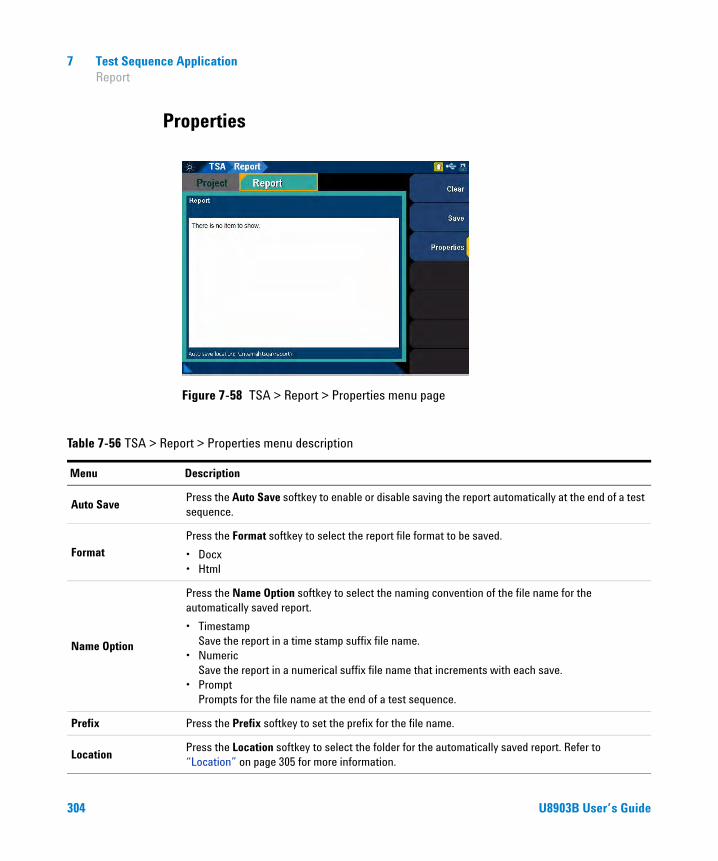
7 Test Sequence Application Report
Properties
Figure 7-58 TSA > Report > Properties menu page
Table 7-56 TSA > Report > Properties menu description
Menu Description
Auto SavePress the Auto Save softkey to enable or disable saving the report automatically at the end of a test sequence.
FormatPress the Format softkey to select the report file format to be saved.
• Docx• Html
Name Option
Press the Name Option softkey to select the naming convention of the file name for the automatically saved report.
• Timestamp Save the report in a time stamp suffix file name.
• Numeric Save the report in a numerical suffix file name that increments with each save.
• Prompt Prompts for the file name at the end of a test sequence.
Prefix Press the Prefix softkey to set the prefix for the file name.
LocationPress the Location softkey to select the folder for the automatically saved report. Refer to “Location” on page 305 for more information.
304 U8903B User’s Guide

Test Sequence Application 7 Report
Location
Select the ‘...’ item at the list and press to move up a level from
the current folder or to another directory. Use the arrow keys to navigate
through the files or select the desired folder or file.
Press the Select softkey to select the current folder as the location to be saved to. Press the New Folder softkey to create a new folder at the current directory or folder.
Figure 7-59 Select Path menu page
Enter
U8903B User’s Guide 305

7 Test Sequence Application Report
THIS PAGE HAS BEEN INTENTIONALLY LEFT BLANK.
306 U8903B User’s Guide

U8903B Audio AnalyzerUser’s Guide
8HP8903B
HP8903B 308Measurement 310Generator 312Sweep 314Code list 315SPCL 318
This chapter describes the various configurations for the HP8903B mode.
NOTE The HP8903B mode is only available when GPIB is initialized successfully. Entering or exiting the HP8903B mode will cause the system to reset. Some of the SCPI commands for the active channel of the analog analyzer and analog generator that work in the standard view mode will not work in the HP8903B mode.
307Agilent Technologies
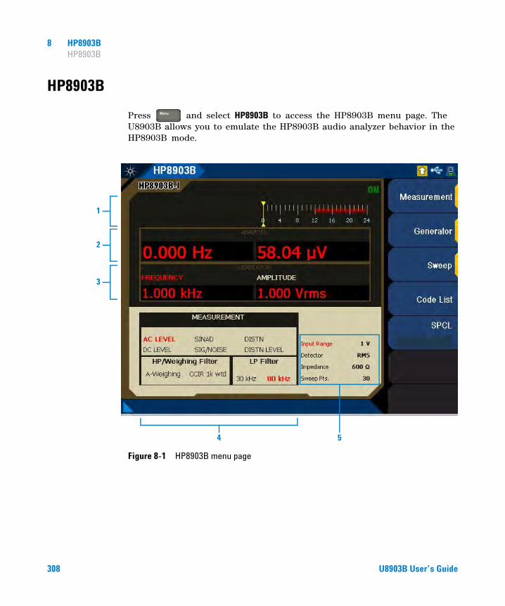
8 HP8903B HP8903B
HP8903B
Press and select HP8903B to access the HP8903B menu page. The U8903B allows you to emulate the HP8903B audio analyzer behavior in the HP8903B mode.
Figure 8-1 HP8903B menu page
Menu
1
2
3
4 5
308 U8903B User’s Guide

HP8903B 8 HP8903B
Table 8-1 U8903B LCD display description
Item Description
1 SINAD meter Display the SINAD measurement mode readings.
2 Analyzer panel
Display the measurement results. The left panel reading shows the frequency result while the right panel reading shows the result of the selected measurement modes. Refer to “Measurement” on page 310 for the available measurement modes.
3 Generator panel
Display the frequency and amplitude values of the sine waveform. The highlighted generator parameter label in red indicates the current increment parameter. You can use the up or down arrow keys to increment/decrement the current parameter value according to the parameter step value. Refer to “Generator” on page 312 for more information.
4 Measurement setting panel Display the current measurement settings in red.
5 HP8903B settings panelDisplay the current setting for input range, detector, impedance, and sweep points. If the auto range is selected, the input range parameter will be highlighted in red.
U8903B User’s Guide 309

8 HP8903B HP8903B
Measurement
Select Measurement in the HP8903B menu page to configure the HP8903B measurement settings.
Figure 8-2 HP8903B > Measurement menu page
Table 8-2 HP8903B > Measurement menu description
Menu Description
Function
Press the Function softkey to select the HP8903B measurement mode.
• AC LEVEL• SINAD• DISTN• DC LEVEL• SIG / NOISE• DISTN LEVEL
LP Filter
Press the LP Filter softkey to select the HP8903B measurement low-pass filter value. The default low-pass filter can be set at “HP8903B Config” on page 55.
• None• 30 kHz• 80 kHz
HP/W FilterPress the HP/W Filter softkey to select the HP8903B high-pass or weighting filter value. The filter selection depends on the left and right filters set at “HP8903B Config” on page 55.
310 U8903B User’s Guide

HP8903B 8 HP8903B
Table 8- 3 shows the measurement units that are applicable for the individual HP8903B measurement modes.
ReferencePress the Reference softkey to set the reference value to be compared with the measured value in ratio mode. Changing the reference value will enable the measurement ratio mode.
Ratio Press the Ratio softkey to enable or disable the HP8903B measurement ratio mode.
FormatPress the Format softkey to select the HP8903B measurement format type.
• Log• Lin
Table 8-2 HP8903B > Measurement menu description (continued)
Menu Description
Table 8-3 HP8903B unit charts
Measurement Ratio On Ratio Off
LOG LIN LOG LIN
AC LEVEL dB % dBm into 600 Ω V
DC LEVEL dB % dBm into 600 Ω V
SINAD dB % dB %
SIG/NOISE dB % dB %
DSTN dB % dB %
DSTN LEVEL dB % dBm into 600 Ω V
U8903B User’s Guide 311

8 HP8903B HP8903B
Generator
Select Generator in the HP8903B menu page to configure the HP8903B generator settings.
Figure 8-3 HP8903B > Generator menu page
NOTE The generator in the HP8903B generates sine waveform.
Table 8-4 HP8903B > Generator menu description
Menu Description
FrequencyPress the Frequency softkey to set the HP8903B generator frequency value. Changing the frequency value will also set the step parameter to frequency.
AmplitudePress the Amplitude softkey to set the HP8903B generator amplitude value. Changing the amplitude value will also set the step parameter to amplitude.
Step ParamPress the Step Param softkey to select the HP8903B generator step parameter type.
• Frequency• Amplitude
312 U8903B User’s Guide

HP8903B 8 HP8903B
Freq. StepPress the Freq. Step softkey to set the HP8903B generator frequency step value. This setting is only available when the step parameter is set to frequency.
Amp. StepPress the Amp. Step softkey to set the HP8903B generator amplitude step value. This setting is only available when the step parameter is set to amplitude.
x 10 Press the x 10 softkey to multiply the current parameter step value by 10.
÷ 10 Press the ÷ 10 softkey to divide the current parameter step value by 10.
Table 8-4 HP8903B > Generator menu description (continued)
Menu Description
U8903B User’s Guide 313

8 HP8903B HP8903B
Sweep
In HP8903B mode, the source frequency is logarithmically swept. The number of frequency points in a sweep is determined by the sweep width (ratio of the stop and start frequencies) and the selected sweep resolution. The maximum number of points allowable in a sweep is 255.
The frequency points in a sweep can be computed by using the following formulas:
Where n is the frequency point number (0 is the start frequency) and k is the number of points per decade. Refer to the HP8903B special function codes, 17.0 to 17.9 as listed in Table 8- 6.
The frequency point formula for reverse sweep is as follows:
Select Sweep in the HP8903B menu page to configure the HP8903B sweep settings.
Figure 8-4 HP8903B > Sweep menu page
Frequency Start frequency 10
nk---⎝ ⎠⎛ ⎞
×=
Frequency Start frequency 10
n–k
-------⎝ ⎠⎛ ⎞
×=
314 U8903B User’s Guide

HP8903B 8 HP8903B
Code list
Select Code List in the HP8903B menu page to display the list of supported HP8903B special function codes. The special function codes will be displayed in the lower main display as shown in Figure 8- 5. Press the up or down arrow keys to scroll up or down the selected special function code list respectively. The HP8903B special function code are as listed in Table 8- 6.
Figure 8-5 HP8903B > Code List menu page (Input Level Range (except DC Level))
Table 8-5 HP8903B > Sweep menu description
Menu Description
Freq. Start Press the Freq. Start softkey to set the HP8903B sweep frequency start value.
Freq. Stop Press the Freq. Stop softkey to set the HP8903B sweep frequency stop value.
Sweep Status Press the Sweep Status softkey to start or abort sweeping in the HP8903B mode.
U8903B User’s Guide 315
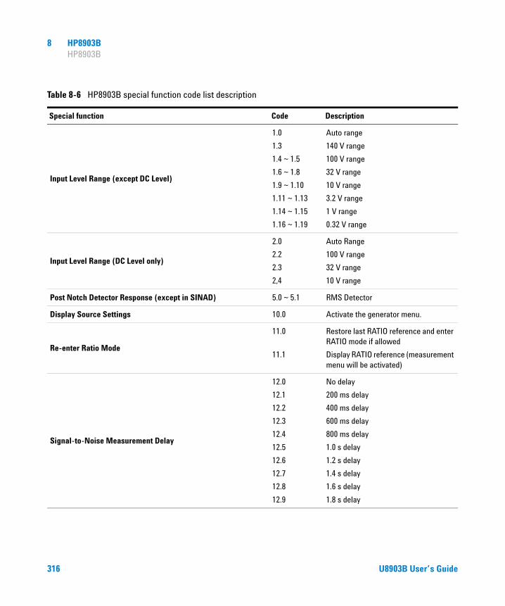
8 HP8903B HP8903B
Table 8-6 HP8903B special function code list description
Special function Code Description
Input Level Range (except DC Level)
1.0
1.3
1.4 ~ 1.5
1.6 ~ 1.8
1.9 ~ 1.10
1.11 ~ 1.13
1.14 ~ 1.15
1.16 ~ 1.19
Auto range
140 V range
100 V range
32 V range
10 V range
3.2 V range
1 V range
0.32 V range
Input Level Range (DC Level only)
2.0
2.2
2.3
2,4
Auto Range
100 V range
32 V range
10 V range
Post Notch Detector Response (except in SINAD) 5.0 ~ 5.1 RMS Detector
Display Source Settings 10.0 Activate the generator menu.
Re-enter Ratio Mode
11.0
11.1
Restore last RATIO reference and enter RATIO mode if allowed
Display RATIO reference (measurement menu will be activated)
Signal-to-Noise Measurement Delay
12.0
12.1
12.2
12.3
12.4
12.5
12.6
12.7
12.8
12.9
No delay
200 ms delay
400 ms delay
600 ms delay
800 ms delay
1.0 s delay
1.2 s delay
1.4 s delay
1.6 s delay
1.8 s delay
316 U8903B User’s Guide

HP8903B 8 HP8903B
SINAD and Signal-to-Noise Display Resolution16.0
16.1
0.01 dB above 25 dB 0.5 dB below 25 dB
0.01 dB all ranges
Sweep Resolution (maximum 255 points/sweep)
17.0
17.1
17.2
17.3
17.4
17.5
17.6
17.7
17.8
17.9
10 points/decade
1 point/decade
2 points/decade
5 points/decade
10 points/decade
20 points/decade
50 points/decade
100 points/decade
200 points/decade
500 points/decade
Display Level in Watts19.0
19.NNN
Display level as watts into 8 ΩDisplay level as watts into NNN Ω
Read Display to SCPI20.0
20.1
Read right display
Read left display (Frequency)
GPIB Address (SCPI Only) 21.1 Displays GPIB address in decimal
GPIB Service Request Condition (SCPI Only) 22.N
Enable a Condition to cause a service request. N is the sum of any combination of the weighted conditions below: 1 - Data Ready 2 - GPIB error 4 - Instrument Error The instrument powers up in the 22.2 state.
Source Output Impedance (Instrument powers up at 600 Ω)47.0
47.1
600 Ω50 Ω
Table 8-6 HP8903B special function code list description (continued)
Special function Code Description
U8903B User’s Guide 317

8 HP8903B HP8903B
SPCL
Press the SPCL softkey to set the HP8903B special function code except those indicated as SCPI only, and execute the special function. The HP8903B special function code are as listed in Table 8- 6.
318 U8903B User’s Guide

U8903B Audio AnalyzerUser’s Guide
9Characteristics and Specifications
Product Characteristics 320
Specifications 321Analog generator specifications 321Analog analyzer specifications 325Analog audio filters 329Graph specifications 330Sweep specifications 331Audio monitor specifications 3311.5 MHz bandwidth (option N3431A) specifications 332POLQA measurement (option N3432A) specifications 332
Measurement Category 333Measurement category definitions 333
This chapter specifies the characteristics and specifications of the U8903B.
319Agilent Technologies

9 Characteristics and Specifications Product Characteristics
Product Characteristics
POWER CONSUMPTION≤250 VA
POWER REQUIREMENTS• 100 VAC to 240 VAC• 47 Hz to 63 Hz• 250 W• MAINS supply voltage fluctuations not to exceed ±10% of the nominal voltage
OPERATING ENVIRONMENTRefer to “Environmental Conditions” on page V
STORAGE COMPLIANCERefer to “Environmental Conditions” on page V
SAFETY AND EMC COMPLIANCERefer to “Regulatory Information” on page V
DIMENSIONS (W × D × H)425.60 mm (16.76 in) × 425.00 mm (16.73 in) × 133.60 mm (5.25 in)
WEIGHT8.5 kg
WARRANTY• Please refer to http://www.agilent.com/go/warranty_terms
• 3 years for the product• 3 months for the standard accessories unless otherwise specified
320 U8903B User’s Guide

Characteristics and Specifications 9 Specifications
Specifications
The following specifications are based on performance with 30 minutes warm- up time and at a temperature of 0 °C to 55 °C unless stated otherwise.
Analog generator specifications
OUTPUT SPECIFICATIONS
GENERATED WAVEFORMS • Sine• Variable phase• Dual sine• SMPTE IMD (1:1/4:1/10:1)• DFD IEC (IEC 60118/IEC 60268)• Square• Noise (Gaussian/Rectangular/Pink)• DC signal• Multitone• Arbitrary• DTMF• Wave file playback
CONNECTION TYPE
Balanced
Unbalanced
Common mode
XLR
BNC
XLR
IMPEDANCE
Balanced
Unbalanced
Common mode
40 Ω,100 Ω, 600 Ω20 Ω, 50 Ω, 600 Ω40 Ω,100 Ω, 600 Ω, or 10 Ω unbalanced as per IEC 60268
GROUNDING • True floating• Grounded
MAXIMUM OUTPUT POWER INTO 600 ΩBalanced (600 Ω)
Unbalanced (600 Ω)
20 dBm
14 dBm
U8903B User’s Guide 321
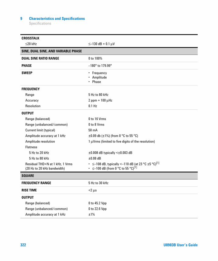
9 Characteristics and Specifications Specifications
CROSSTALK
≤20 kHz ≤–130 dB + 0.1 μV
SINE, DUAL SINE, AND VARIABLE PHASE
DUAL SINE RATIO RANGE 0 to 100%
PHASE –180° to 179.99°
SWEEP • Frequency• Amplitude• Phase
FREQUENCY
Range
Accuracy
Resolution
5 Hz to 80 kHz
2 ppm + 100 μHz
0.1 Hz
OUTPUT
Range (balanced)
Range (unbalanced/common)
Current limit (typical)
Amplitude accuracy at 1 kHz
Amplitude resolution
Flatness
5 Hz to 20 kHz
5 Hz to 80 kHz
Residual THD+N at 1 kHz, 1 Vrms (20 Hz to 20 kHz bandwidth)
0 to 16 Vrms
0 to 8 Vrms
50 mA
±0.09 db (±1%) (from 0 °C to 55 °C)
1 μVrms (limited to five digits of the resolution)
±0.008 dB typically <±0.003 dB
±0.08 dB
• ≤–108 dB, typically <–110 dB (at 23 °C ±5 °C)[1]
• ≤–100 dB (from 0 °C to 55 °C)[1]
SQUARE
FREQUENCY RANGE 5 Hz to 30 kHz
RISE TIME <2 μs
OUTPUT
Range (balanced)
Range (unbalanced/common)
Amplitude accuracy at 1 kHz
0 to 45.2 Vpp
0 to 22.6 Vpp
±1%
322 U8903B User’s Guide

Characteristics and Specifications 9 Specifications
SMPTE IMD (1:1/4:1/10:1)
MIXED RATIO (LF:HF) • 10:1• 4:1• 1:1
RESIDUAL IMD (20 Hz to 20 kHz) • ≤–95 dB (at 23 °C ±5 °C)• ≤–90 dB (0 °C to 55 °C)
SWEEP • Upper frequency• Lower frequency• Amplitude
FREQUENCY
Low-frequency (LF) tone
High-frequency (HF) tone
40 Hz to 500 Hz
2 kHz to 60 kHz
OUTPUT
Range (balanced)
Range (unbalanced/common)
0 to 16 Vrms
0 to 8 Vrms
DFD (IEC 60118/IEC 60268)
INHERENT DISTORTION (20 Hz TO 20 kHz) ≤–106 dB at 1 Vrms
SWEEP • Upper frequency• Center frequency• Amplitude
FREQUENCY
Difference frequency
Upper frequency
Center frequency
80 Hz to 2 kHz
3 kHz to 80 kHz
3 kHz to 79 kHz
OUTPUT
Range (balanced)
Range (unbalanced/common)
0 to 16 Vrms
0 to 8 Vrms
U8903B User’s Guide 323

9 Characteristics and Specifications Specifications
NOISE
TYPE • Gaussian• Rectangular• Pink
OUTPUT
Range (balanced)
Range (unbalanced/common)
• 0 to 7.2 Vrms (Gaussian)• 0 to 10 Vrms (Rectangular)• 0 to 7.2 Vrms (Pink)
• 0 to 3.6 Vrms (Gaussian)• 0 to 5 Vrms (Rectangular)• 0 to 3.6 Vrms (Pink)
ARBITRARY
SIGNAL Determined by the user selected file
SAMPLE RATE 192 kHz
LENGTH Up to 5 minutes depending on the waveform file
MULTITONE
SIGNAL Determined by the user specified frequency, amplitude, and phase data
SAMPLE RATE 192 kHz
LENGTH 1024 to 65536 points/channel
MAXIMUM NUMBER OF TONES 64
WAVE FILE PLAYBACK
TYPE OF FILE .WAV file
SAMPLE RATE 192 kHz
LENGTH Up to 5 minutes depending on the waveform file
DC
OUTPUT
Range (balanced)
Range (unbalanced/common)
Amplitude accuracy
–22.6 V to 22.6 V
–11.3 V to 11.3 V
±1%
324 U8903B User’s Guide
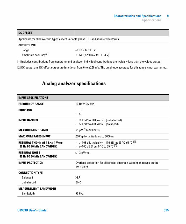
Characteristics and Specifications 9 Specifications
Analog analyzer specifications
DC OFFSET
Applicable for all waveform types except variable phase, DC, and square waveforms.
OUTPUT LEVEL
Range
Amplitude accuracy[2]
–11.3 V to 11.3 V
±1.5% (±250 mV to ±11.3 V)
[1] Includes contributions from generator and analyzer. Individual contributions are typically less than the values stated.
[2] DC output and DC offset output are functional from 0 to ±250 mV. The amplitude accuracy for this range is not warranted.
INPUT SPECIFICATIONS
FREQUENCY RANGE 10 Hz to 96 kHz
COUPLING • DC• AC
INPUT RANGES • 320 mV to 140 Vrms[1] (unbalanced)• 320 mV to 300 Vrms[1] (balanced)
MEASUREMENT RANGE <1 μV[2] to 300 Vrms
MAXIMUM RATED INPUT 200 Vp for altitude up to 3000 m
RESIDUAL THD+N AT 1 kHz, 1 Vrms (20 Hz TO 20 kHz BANDWIDTH)
• ≤–108 dB, typically <–110 dB (at 23 °C ±5 °C)[3]
• ≤–100 dB (from 0 °C to 55 °C)[3]
RESIDUAL NOISE (20 Hz TO 20 kHz BANDWIDTH)
≤1.3 μVrms
INPUT PROTECTION Overload protection for all ranges; onscreen warning message on the front panel
CONNECTION TYPE
Balanced
Unbalanced
XLR
BNC
MEASUREMENT BANDWIDTH
Bandwidth 96 kHz
U8903B User’s Guide 325

9 Characteristics and Specifications Specifications
IMPEDANCE
Balanced
Unbalanced
• 300 Ω (3 W maximum)• 600 Ω (1.5 W maximum)• 200 kΩ• 300 Ω (3 W maximum)• 600 Ω (1.5 W maximum)• 100 kΩ
CMRR
≤20 kHz (input range ≤3.2 V)
≤20 kHz (input range >3.2 V)
≥80 dB[4]
≥50 dB[4]
CROSSTALK
≤20 kHz ≤–140 dB + 0.1 μV
THD+N AND SINAD
DISPLAY RANGE –999.999 dB to 0 dB
ACCURACY
<20 kHz
<100 kHz
±0.5 dB
±0.7 dB
INPUT VOLTAGE RANGE <1 μV to 140 Vrms
3 dB MEASUREMENT BANDWIDTH 96 kHz
DETECTION RMS
DISPLAY RESOLUTION % up to 3 decimal places (dB up to 2 decimal places)
SNR
DISPLAY RANGE –999.999 dB to 0 dB
ACCURACY
<20 kHz
<100 kHz
±0.5 dB
±0.7 dB
INPUT VOLTAGE RANGE <1 μV to 140 Vrms
326 U8903B User’s Guide

Characteristics and Specifications 9 Specifications
TRIGGERING
TYPE • Free run• External
LEVEL 5 V
MINIMUM TRIGGER HIGH VOLTAGE 1.25 V
MAXIMUM TRIGGER LOW VOTAGE 0.5 V
INPUT IMPEDANCE >10 kΩ
AMPLITUDE
DC MEASUREMENT RANGE 0 V to ±200 V
DC ACCURACY ±1%
AC ACCURACY AT 1 kHz • 0.03 dB (0.35%) (at 23 °C ±5 °C)• 0.05 dB (0.58%) (from 0 °C to 55 °C)
FLATNESS REFERENCE 1 kHz
≤20 kHz
≤80 kHz
≤96 kHz
±0.008 dB, typically <±0.003 dB
±0.08 dB
±0.1 dB
AC LEVEL DETECTION • RMS• Peak-to-peak
FREQUENCY
RANGE 10 Hz to 96 kHz
MINIMUM INPUT 1 mV (S/N > 40 dB)
ACCURACY • 2 ppm + 100 μHz (≤50 kHz)• <5 ppm (>50 kHz)
RESOLUTION 6 digits
U8903B User’s Guide 327
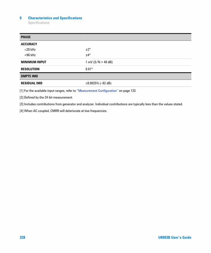
9 Characteristics and Specifications Specifications
PHASE
ACCURACY
<20 kHz
<96 kHz
±2°
±4°
MINIMUM INPUT 1 mV (S/N > 40 dB)
RESOLUTION 0.01°
SMPTE IMD
RESIDUAL IMD ≤0.0025% (–92 dB)
[1] For the available input ranges, refer to “Measurement Configuration” on page 133.
[2] Defined by the 24-bit measurement.
[3] Includes contributions from generator and analyzer. Individual contributions are typically less than the values stated.
[4] When AC coupled, CMRR will deteriorate at low frequencies.
328 U8903B User’s Guide
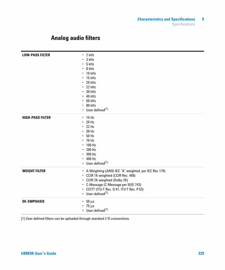
Characteristics and Specifications 9 Specifications
Analog audio filters
LOW-PASS FILTER • 2 kHz• 3 kHz• 5 kHz• 8 kHz• 10 kHz• 15 kHz• 20 kHz• 22 kHz• 30 kHz• 40 kHz• 50 kHz• 80 kHz• User-defined[1]
HIGH-PASS FILTER • 15 Hz• 20 Hz• 22 Hz• 30 Hz• 50 Hz• 70 Hz• 100 Hz• 200 Hz• 300 Hz• 400 Hz• User-defined[1]
WEIGHT FILTER • A Weighting (ANSI-IEC “A” weighted, per IEC Rec 179)• CCIR 1K weighted (CCIR Rec. 468)• CCIR 2K weighted (Dolby 2K)• C-Message (C-Message per IEEE 743)• CCITT (ITU-T Rec. O.41, ITU-T Rec. P.53)• User-defined[1]
DE-EMPHASIS • 50 μs• 75 μs• User-defined[1]
[1] User-defined filters can be uploaded through standard I/O connections.
U8903B User’s Guide 329

9 Characteristics and Specifications Specifications
Graph specifications
FFT ANALYZER
SAMPLE SIZE • 2048• 4096• 8192• 16384• 32768• 65536• 131072• 262144• 524288• 1M• 2M
WINDOW • Rectangular• Hanning• Blackman• Rife-Vincent• Rife-Vincent 3• Hamming• Flat top• Kaiser
AMPLITUDE ACCURACY (FLAT TOP WINDOW)
±0.1 dB (±1.2%)
330 U8903B User’s Guide
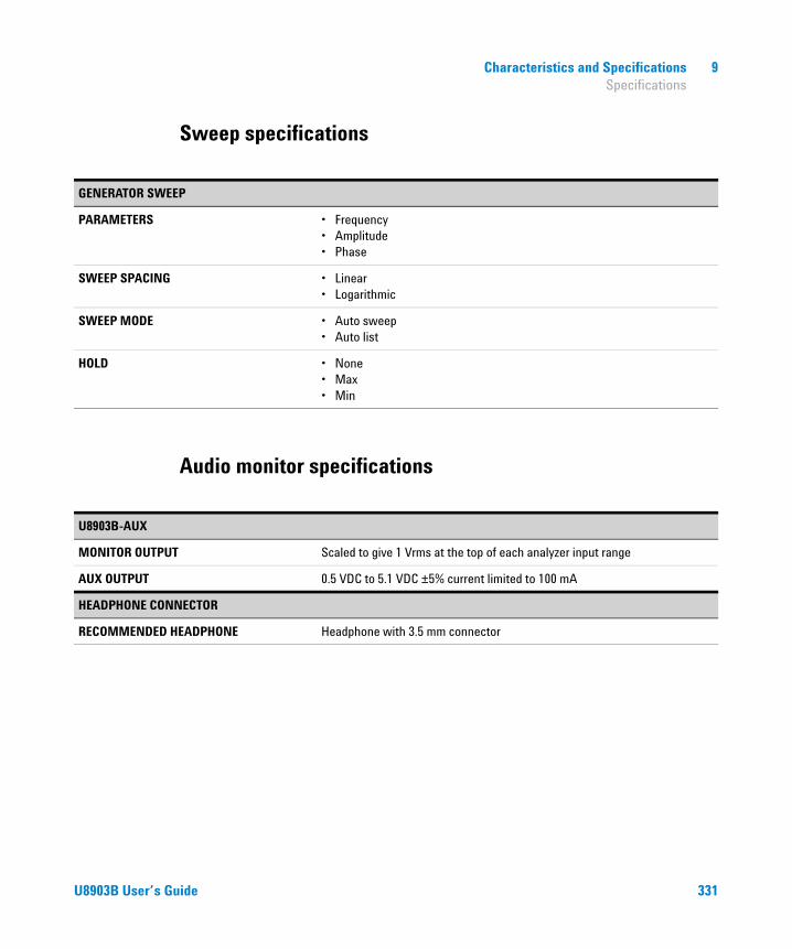
Characteristics and Specifications 9 Specifications
Sweep specifications
Audio monitor specifications
GENERATOR SWEEP
PARAMETERS • Frequency• Amplitude• Phase
SWEEP SPACING • Linear• Logarithmic
SWEEP MODE • Auto sweep• Auto list
HOLD • None• Max• Min
U8903B-AUX
MONITOR OUTPUT Scaled to give 1 Vrms at the top of each analyzer input range
AUX OUTPUT 0.5 VDC to 5.1 VDC ±5% current limited to 100 mA
HEADPHONE CONNECTOR
RECOMMENDED HEADPHONE Headphone with 3.5 mm connector
U8903B User’s Guide 331
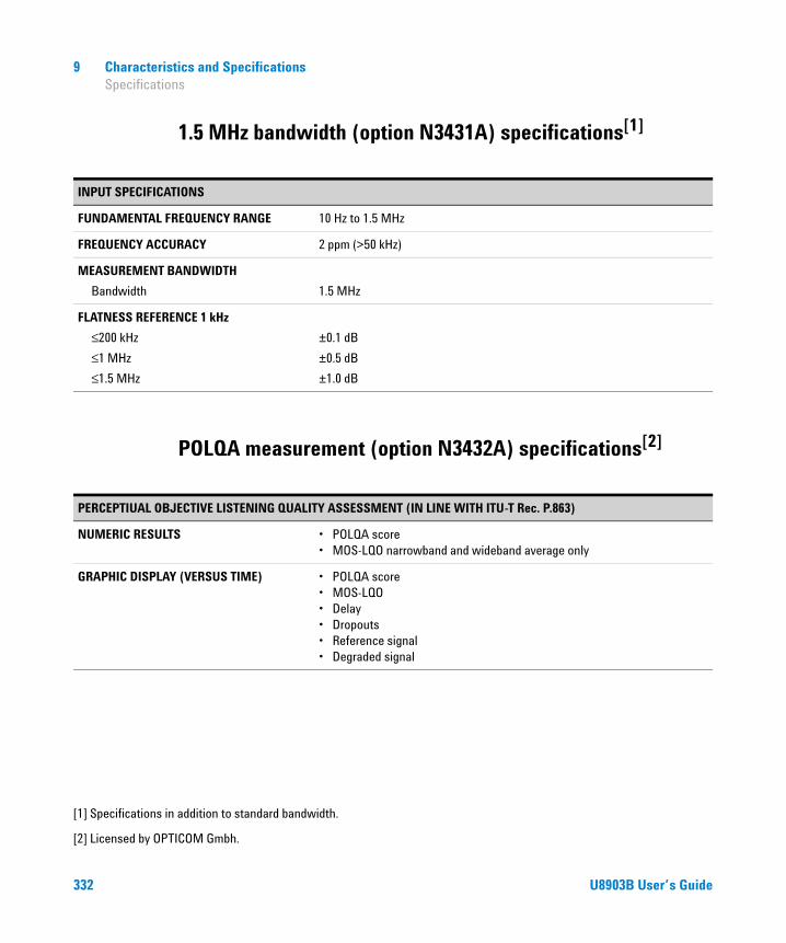
9 Characteristics and Specifications Specifications
1.5 MHz bandwidth (option N3431A) specifications[1]
POLQA measurement (option N3432A) specifications[2]
[1] Specifications in addition to standard bandwidth.
INPUT SPECIFICATIONS
FUNDAMENTAL FREQUENCY RANGE 10 Hz to 1.5 MHz
FREQUENCY ACCURACY 2 ppm (>50 kHz)
MEASUREMENT BANDWIDTH
Bandwidth 1.5 MHz
FLATNESS REFERENCE 1 kHz
≤200 kHz
≤1 MHz
≤1.5 MHz
±0.1 dB
±0.5 dB
±1.0 dB
[2] Licensed by OPTICOM Gmbh.
PERCEPTIUAL OBJECTIVE LISTENING QUALITY ASSESSMENT (IN LINE WITH ITU-T Rec. P.863)
NUMERIC RESULTS • POLQA score• MOS-LQO narrowband and wideband average only
GRAPHIC DISPLAY (VERSUS TIME) • POLQA score• MOS-LQO• Delay• Dropouts• Reference signal• Degraded signal
332 U8903B User’s Guide
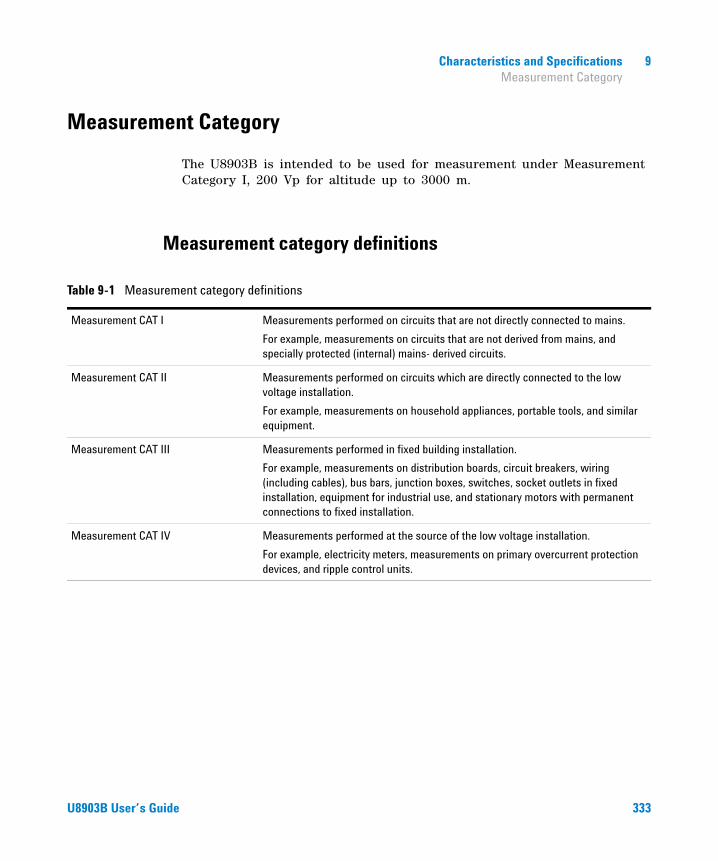
Characteristics and Specifications 9 Measurement Category
Measurement Category
The U8903B is intended to be used for measurement under Measurement Category I, 200 Vp for altitude up to 3000 m.
Measurement category definitions
Table 9-1 Measurement category definitions
Measurement CAT I Measurements performed on circuits that are not directly connected to mains.
For example, measurements on circuits that are not derived from mains, and specially protected (internal) mains- derived circuits.
Measurement CAT II Measurements performed on circuits which are directly connected to the low voltage installation.
For example, measurements on household appliances, portable tools, and similar equipment.
Measurement CAT III Measurements performed in fixed building installation.
For example, measurements on distribution boards, circuit breakers, wiring (including cables), bus bars, junction boxes, switches, socket outlets in fixed installation, equipment for industrial use, and stationary motors with permanent connections to fixed installation.
Measurement CAT IV Measurements performed at the source of the low voltage installation.
For example, electricity meters, measurements on primary overcurrent protection devices, and ripple control units.
U8903B User’s Guide 333

9 Characteristics and Specifications Measurement Category
THIS PAGE HAS BEEN INTENTIONALLY LEFT BLANK.
334 U8903B User’s Guide
U8903B Audio AnalyzerUser’s Guide
Appendixes
Appendix A: FUNCTION panel 336
Appendix B: Graph Panel Menu Tree 337
Appendix C: System Panel Menu Tree 339
Appendix D: Analog Generator Menu Tree 344
Appendix E: Analog Analyzer Menu Tree 349
Appendix F: Graph Analysis Menu Tree 362
Appendix G: Sweep Function Menu Tree 367
Appendix H: Save Menu Tree 370
Appendix I: Recall Menu Tree 371
Appendix J: Test Sequence Menu Tree 372Measurement settings 383
Appendix K: HP8903B Menu Tree 430
Appendix L: Units of the Measurement Function Returned Values 432Analog analyzer 432
Appendix M: Arbitrary File Format 435
Appendix N: User-defined Filter File Format 438
Appendix O: U8903B Default Settings 441
335Agilent Technologies

A Appendixes Appendix A: FUNCTION panel
Appendix A: FUNCTION panel
Table A-1 FUNCTION panel description
Key Description
Interface Reserved for future expansion.
Generator|AnalyzerSwitch between the generator or analyzer mode.
Refer to “Appendix D: Analog Generator Menu Tree” and “Appendix E: Analog Analyzer Menu Tree” for the analog generator and analog analyzer menu trees.
GraphAccess the graph analysis mode.
Refer to “Appendix F: Graph Analysis Menu Tree” for the graph analysis menu tree.
SweepAccess the sweep function mode.
Refer to “Appendix G: Sweep Function Menu Tree” for the sweep function menu tree.
Full ScreenMaximize the graph view to the full display size.
This function is only applicable in the graph analysis mode.
DisplaySwitch among the 2-panel view, 4-panel view, or 10-panel view in the analyzer and generator mode.
Switch between single panel view and 2-panel view in the graph analysis mode.
Shortcut 1Customizable shortcut key. Refer to “Appendix C: System Panel Menu Tree” on page 339 for more information.
Shortcut 2Customizable shortcut key. Refer to “Appendix C: System Panel Menu Tree” on page 339 for more information.
336 U8903B User’s Guide
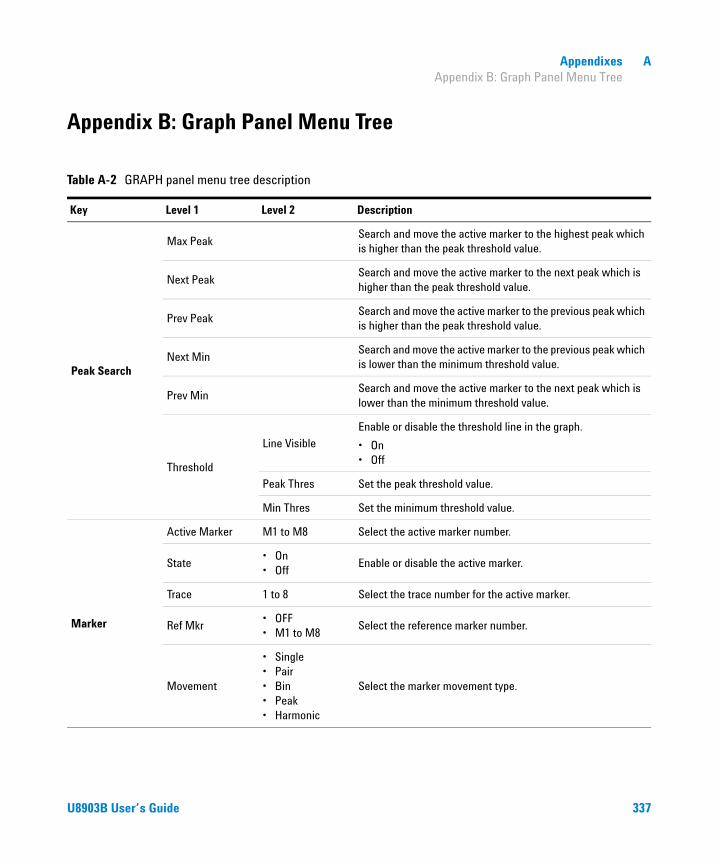
Appendixes A Appendix B: Graph Panel Menu Tree
Appendix B: Graph Panel Menu Tree
Table A-2 GRAPH panel menu tree description
Key Level 1 Level 2 Description
Peak Search
Max PeakSearch and move the active marker to the highest peak which is higher than the peak threshold value.
Next PeakSearch and move the active marker to the next peak which is higher than the peak threshold value.
Prev PeakSearch and move the active marker to the previous peak which is higher than the peak threshold value.
Next MinSearch and move the active marker to the previous peak which is lower than the minimum threshold value.
Prev MinSearch and move the active marker to the next peak which is lower than the minimum threshold value.
Threshold
Line Visible
Enable or disable the threshold line in the graph.
• On• Off
Peak Thres Set the peak threshold value.
Min Thres Set the minimum threshold value.
Marker
Active Marker M1 to M8 Select the active marker number.
State• On• Off
Enable or disable the active marker.
Trace 1 to 8 Select the trace number for the active marker.
Ref Mkr• OFF• M1 to M8
Select the reference marker number.
Movement
• Single• Pair• Bin• Peak• Harmonic
Select the marker movement type.
U8903B User’s Guide 337

A Appendixes Appendix B: Graph Panel Menu Tree
Marker
Function• None• Slope• PSD
Select the marker function type.
Marker ->
-> Start Set the left value of the graph to the current marker location.
-> Stop Set the right value of the graph to the current marker location.
-> CenterSet the center value of the graph to the current marker location.
-> Delta
Set the left and right values of the graph to the current marker and the
reference marker location.
Move to 3 dB Place the marker on the nearest –3 dB value data point.
Move to 6 dB Place the marker on the nearest –6 dB value data point.
Harmonics
Trace Set the trace number to place the marker.
Enabled
Show or hide the markers.
• On• Off
Rdg at Mkr• On• Off
Enable or disable the readings at the marker.
Print (Shift + Marker)
Print the current display to a file.
Scale
AutoScale Perform autoscaling on the X-axis and Y-axis.
AutoScale XPerform autoscaling on the X-axis by searching for the most optimum scale (left and right values) for the X-axis based on the data being displayed in the graph.
AutoScale YPerform autoscaling on the Y-axis by searching for the most optimum scale (top and bottom values) for the Y-axis based on the data being displayed in the graph.
Zoom Magnify a section of the graph.
Table A-2 GRAPH panel menu tree description (continued)
Key Level 1 Level 2 Description
338 U8903B User’s Guide
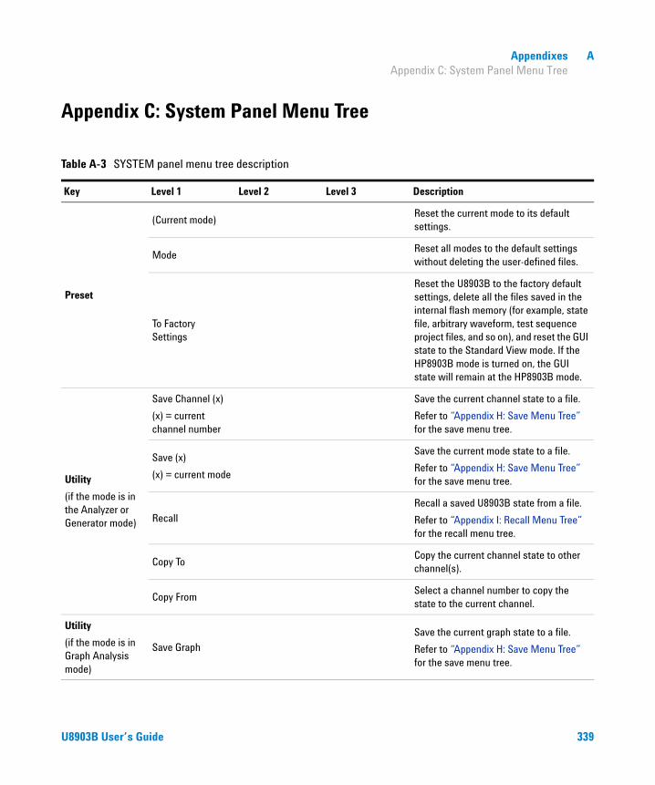
Appendixes A Appendix C: System Panel Menu Tree
Appendix C: System Panel Menu Tree
Table A-3 SYSTEM panel menu tree description
Key Level 1 Level 2 Level 3 Description
Preset
(Current mode)Reset the current mode to its default settings.
ModeReset all modes to the default settings without deleting the user-defined files.
To Factory Settings
Reset the U8903B to the factory default settings, delete all the files saved in the internal flash memory (for example, state file, arbitrary waveform, test sequence project files, and so on), and reset the GUI state to the Standard View mode. If the HP8903B mode is turned on, the GUI state will remain at the HP8903B mode.
Utility
(if the mode is in the Analyzer or Generator mode)
Save Channel (x)
(x) = current channel number
Save the current channel state to a file.
Refer to “Appendix H: Save Menu Tree” for the save menu tree.
Save (x)
(x) = current mode
Save the current mode state to a file.
Refer to “Appendix H: Save Menu Tree” for the save menu tree.
Recall
Recall a saved U8903B state from a file.
Refer to “Appendix I: Recall Menu Tree” for the recall menu tree.
Copy ToCopy the current channel state to other channel(s).
Copy FromSelect a channel number to copy the state to the current channel.
Utility
(if the mode is in Graph Analysis mode)
Save Graph
Save the current graph state to a file.
Refer to “Appendix H: Save Menu Tree” for the save menu tree.
U8903B User’s Guide 339

A Appendixes Appendix C: System Panel Menu Tree
Utility
(if the mode is in Graph Analysis mode)
Save Channels Settings
Channel (x)
(x) = current channel
Save the current channel graph state to a file.
Refer to “Appendix H: Save Menu Tree” for the save menu tree.
All Channels Settings
Save all channels graph state to a file.
Refer to “Appendix H: Save Menu Tree” for the save menu tree.
Save Traces
Trace (x)
(x) = current trace number
Save the active trace to a CSV file format.
Refer to “Appendix H: Save Menu Tree” for the save menu tree.
All Traces
Save all traces state to a file.
Refer to “Appendix H: Save Menu Tree” for the save menu tree.
Axis Settings
Save the axis settings state to a file.
Refer to “Appendix H: Save Menu Tree” for the save menu tree.
Traces + Axis
Save all traces and axis settings states.
Refer to “Appendix H: Save Menu Tree” for the save menu tree.
Save Trace (x) Data
(x) = current channel
Save the active trace data to a CSV file format.
Refer to “Appendix H: Save Menu Tree” for the save menu tree.
Recall
Load a trace from a CSV file into the active trace.
Refer to “Appendix I: Recall Menu Tree” for the recall menu tree.
Copy ToCopy the current channel graph state to other channel(s).
Copy Graph FromSelect a channel number to copy the graph state to the current channel.
Table A-3 SYSTEM panel menu tree description
Key Level 1 Level 2 Level 3 Description
340 U8903B User’s Guide

Appendixes A Appendix C: System Panel Menu Tree
Help (Shift + Utility)
Display the help mode.
Press Shift + Utility to close the help mode.
System
Error Info Load File
Select the log file to be loaded in the error log viewing panel.
Refer to “Appendix I: Recall Menu Tree” for the recall menu tree.
I/O LAN SettingsReset Reset the LAN settings.
Hostname Set the LAN hostname.
I/O
LAN Settings
Config Mode
Select the LAN configuration mode.
• Auto• Manual
IP Address Set the LAN IP address.
Subnet mask Set the LAN subnet mask address.
Gateway Set the LAN gateway address.
DNS 1 Set the LAN DNS 1 address.
DNS 2 Set the LAN DNS 2 address.
GPIB 0 to 30 Set the desired GPIB address.
FTP• Enabled• Disabled
Enable or disable the FTP control.
UpdateLoad File
Load the update files.
Refer to “Appendix I: Recall Menu Tree” for the recall menu tree.
EULA Display the Agilent EULA page.
Service Self-Test
Customize Test
Select all or deselect the desired tests.
• LAN Test• Card Self Test
Run Test Run the selected tests.
Clear Result Clear the previous self-test results.
Table A-3 SYSTEM panel menu tree description
Key Level 1 Level 2 Level 3 Description
U8903B User’s Guide 341
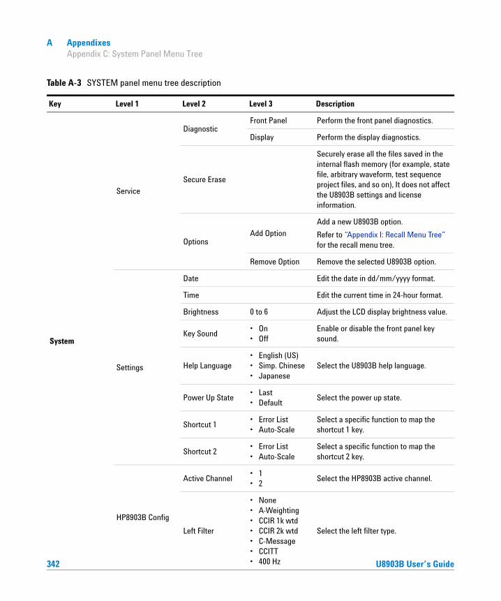
A Appendixes Appendix C: System Panel Menu Tree
System
Service
DiagnosticFront Panel Perform the front panel diagnostics.
Display Perform the display diagnostics.
Secure Erase
Securely erase all the files saved in the internal flash memory (for example, state file, arbitrary waveform, test sequence project files, and so on), It does not affect the U8903B settings and license information.
OptionsAdd Option
Add a new U8903B option.
Refer to “Appendix I: Recall Menu Tree” for the recall menu tree.
Remove Option Remove the selected U8903B option.
Settings
Date Edit the date in dd/mm/yyyy format.
Time Edit the current time in 24-hour format.
Brightness 0 to 6 Adjust the LCD display brightness value.
Key Sound• On• Off
Enable or disable the front panel key sound.
Help Language• English (US)• Simp. Chinese• Japanese
Select the U8903B help language.
Power Up State• Last• Default
Select the power up state.
Shortcut 1• Error List• Auto-Scale
Select a specific function to map the shortcut 1 key.
Shortcut 2• Error List• Auto-Scale
Select a specific function to map the shortcut 2 key.
HP8903B Config
Active Channel• 1• 2
Select the HP8903B active channel.
Left Filter
• None• A-Weighting• CCIR 1k wtd• CCIR 2k wtd• C-Message
Select the left filter type.
Table A-3 SYSTEM panel menu tree description
Key Level 1 Level 2 Level 3 Description
342 U8903B User’s Guide
• CCITT• 400 Hz

Appendixes A Appendix C: System Panel Menu Tree
System
HP8903B Config
Right Filter
• None• A-Weighting• CCIR 1k wtd• CCIR 2k wtd• C-Message• CCITT• 400 Hz
Select the right filter value.
Default LPF• None• 30 kHz• 80 kHz
Select the default filter for the HP8903B mode.
Fan & TemperatureDisplay the temperatures of the available cards and the speed of the three 80 mm fans in the U8903B.
Aux Output
Audio Monitor• On• Off
Enable or disable the aux audio monitor.
Audio Output• Speaker• Phone
Select the aux audio output type.
Audio Mode• Stereo• Mono
Select the aux audio mode type.
Volume 0 to 100 Select the aux audio volume.
DC Output Set the aux DC output value.
Board InfoDisplay the U8903B available cards information.
Macro
(Shift + System)Reserved for future expansion.
LocalSwitch from remote control mode to local mode. The front panel keys are locked in the remote mode.
Lock/UnlockLock or unlock the front panel keys in the local mode.
A dialog box will pop-up for confirmation.
Table A-3 SYSTEM panel menu tree description
Key Level 1 Level 2 Level 3 Description
U8903B User’s Guide 343

A Appendixes Appendix D: Analog Generator Menu Tree
Appendix D: Analog Generator Menu Tree
Table A-4 Analog generator menu tree description
Level 1 Level 2 Level 3 Description
Waveform
• Sine• V. Phase• Dual• SMPTE 1:1• SMPTE 4:1• SMPTE 10:1• IEC 60118• IEC 60268• Gaus. Noise• Rect. Noise• Pink Noise• Square• DC• Arbitrary• Multitone• DTMF• Playback
Select the waveform type.
Waveform Config (Sine)
Amplitude Set the signal amplitude value.
Frequency Set the signal frequency value.
DC Offset Set the signal DC offset value,
Waveform Config (V. Phase)
Amplitude Set the signal amplitude value.
Frequency Set the signal frequency value.
Phase -> 1
Set the phase of the channel 2 sine waveform with reference to channel 1.
This is only available when the analog generator is in channel 2.
Waveform Config (Dual)
Amplitude Set the signal amplitude value.
Frequency Set the signal frequency value.
Frequency 2Set the second sine wave signal frequency value.
This setting is only applicable for the dual waveform.
344 U8903B User’s Guide

Appendixes A Appendix D: Analog Generator Menu Tree
Waveform Config (Dual)
DC Offset Set the signal DC offset value,
RatioSet the ratio of the amplitude of the second sine wave over the first sine wave.
Waveform Config (SMPTE 1:1/4:1/10:1)
Amplitude Set the signal amplitude value.
Lower Freq Set the lower frequency value.
Upper Freq Set the higher frequency value.
DC Offset Set the signal DC offset value,
Waveform Config (IEC 60118)
Amplitude Set the signal amplitude value.
Upper Freq Set the higher frequency value.
Diff Freq Set the difference frequency of the waveform.
DC Offset Set the signal DC offset value,
Waveform Config (IEC 60268)
Amplitude Set the signal amplitude value.
Center Freq Set the center frequency of the waveform.
Diff Freq Set the difference frequency of the waveform.
DC Offset Set the signal DC offset value,
Waveform Config (Gaus. Noise)
Amplitude Set the signal amplitude value.
DC Offset Set the signal DC offset value,
Waveform Config (Rect. Noise)
Amplitude Set the signal amplitude value.
DC Offset Set the signal DC offset value,
Waveform Config (Pink Noise)
Amplitude Set the signal amplitude value.
DC Offset Set the signal DC offset value,
Waveform Config (Square)
Amplitude Set the signal amplitude value.
Frequency Set the signal frequency value.
Waveform Config (DC)
Voltage Set the signal amplitude value.
Table A-4 Analog generator menu tree description (continued)
Level 1 Level 2 Level 3 Description
U8903B User’s Guide 345

A Appendixes Appendix D: Analog Generator Menu Tree
Waveform Config (Abitrary)
Amplitude Set the signal amplitude value.
DC Offset Set the signal DC offset value,
Load File
Load a waveform from a file.
Refer to “Appendix I: Recall Menu Tree” for the recall menu tree.
Info Display the loaded waveform information.
Waveform Config (Multitone)
Amplitude Set the signal amplitude value.
DC Offset Set the signal DC offset value,
Start FreqSet the lowest frequency in the multitone waveform which is usually the frequency for the first tone.
Stop FreqSet the highest frequency in the multitone waveform which is usually the frequency for the last tone.
Freq Spacing• Linear• Log• Custom
Select frequency spacing between the tones.
Custom is selected when the custom multitone waveform is set.
Tones Set the number of signal frequency components.
Length
• 1024• 2048• 4096• 8192• 16384• 32768• 65536
Select the waveform length that determines the number of samples used to create one iteration of the multitone waveform.
Custom
ApplyApply the current setting on the selected tone for the custom multitone waveform.
Optimize Optimize the crest factor for the custom multitone waveform.
Frequency Set the frequency value for the custom multitone waveform.
Amplitude Set the amplitude value for the custom multitone waveform.
Phase Set the phase value for the custom multitone waveform.
Table A-4 Analog generator menu tree description (continued)
Level 1 Level 2 Level 3 Description
346 U8903B User’s Guide

Appendixes A Appendix D: Analog Generator Menu Tree
Waveform Config (Multitone)
Custom
Add AboveAdd the tone above the selected tone for the custom multitone waveform.
Add BelowAdd the tone below the selected tone for the custom multitone waveform.
Remove Remove the selected tone for the custom multitone waveform.
Clear Clear all the tones in the custom multitone waveform list.
Waveform Config (DTMF)
Dial
Mode
Select the mode of operation for the dial mode.
• Single• Sequence
A B C D
Single dial mode
• Press and hold the A, B, C, or D softkey to dial the A, B, C, or D tone respectively.
Sequence dial mode
• Press the A, B, C, or D softkey to add the A tone to the DTMF sequence.
Pause Add a pause to the DTMF sequence in the form of a comma.
Amplitude Set the sum level of the DTMF signal.
RatioSet the level difference between the high-frequency tone and low-frequency tone.
Tone Duration Set the DTMF signal duration.
Tone Delay Set the delay between two DTMF tones.
Pause Time Set the interval time for the DTMF sequence.
Repeat Enable or disable repeating the DTMF sequence.
Table A-4 Analog generator menu tree description (continued)
Level 1 Level 2 Level 3 Description
U8903B User’s Guide 347

A Appendixes Appendix D: Analog Generator Menu Tree
Output Config
Connector
• Bal• UnBal• Com• IEC60268
Select the output connector type.
Impedance
For Bal, Com, and IEC60268
• 600 Ω• 100 Ω• 40 ΩFor UnBal
• 600 Ω• 50 Ω• 20 Ω
Select the output impedance value.
IEC60268 10 Ω • Pin 2• Pin 3
Select the additional 10 Ω output series resistance for pin 2 or 3 of the XLR connector in the common IECIEC 6026860268 configuration.
This setting is only available when the output connector type is set to IEC 60268.
Ground• Float• Ground
Select the grounding type.
Max Voltage Set the maximum voltage value.
References Ref ImpedanceSet the reference impedance for the unit conversion of dBm measurements.
Table A-4 Analog generator menu tree description (continued)
Level 1 Level 2 Level 3 Description
348 U8903B User’s Guide

Appendixes A Appendix E: Analog Analyzer Menu Tree
Appendix E: Analog Analyzer Menu Tree
Table A-5 Analog analyzer menu tree description
Level 1 Level 2 Level 3 Description
Functions
Multi-Chn• Off• Phase• X-Talk
Select the multichannel mode.
Function No.
• 1• 2• 3• 4
Select the active function number to configure the settings.
Meas. Func.
• None• Frequency• AC Voltage• DC Voltage• THD+N Ratio• THD+N Level• SINAD• THD Ratio• THD Level• SMPTE IMD• DFD60268 2nd• DFD 60268 3rd• DFD 60118 2nd• DFD 60118 3rd• SNR• SNR (Fast)
Select the measurement function.
This setting is only available when the multichannel mode is set to Off.
Functions (Frequency)
Unit• Hz• ΔHz
Select the unit type.
Format• Off• Delta
Select the reading format of the returned measurement reading.
Set result as ref. from
Channels 1 to 8Store the measurement result from the selected channel as the reference frequency.
Ref. Freq Set the reference frequency value.
U8903B User’s Guide 349
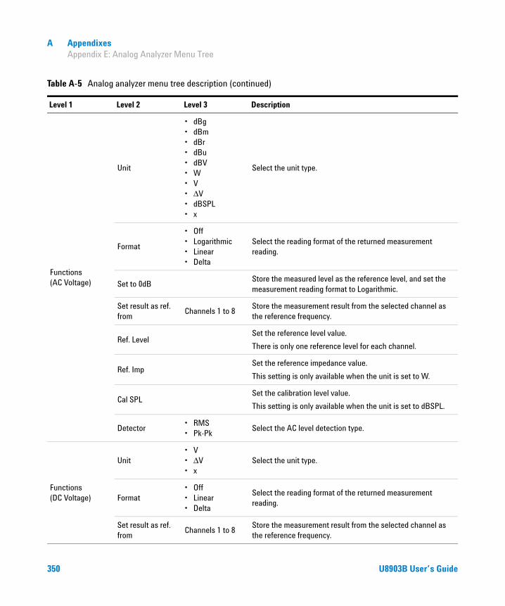
A Appendixes Appendix E: Analog Analyzer Menu Tree
Functions (AC Voltage)
Unit
• dBg• dBm• dBr• dBu• dBV• W• V• ΔV• dBSPL• x
Select the unit type.
Format
• Off• Logarithmic• Linear• Delta
Select the reading format of the returned measurement reading.
Set to 0dBStore the measured level as the reference level, and set the measurement reading format to Logarithmic.
Set result as ref. from
Channels 1 to 8Store the measurement result from the selected channel as the reference frequency.
Ref. LevelSet the reference level value.
There is only one reference level for each channel.
Ref. ImpSet the reference impedance value.
This setting is only available when the unit is set to W.
Cal SPLSet the calibration level value.
This setting is only available when the unit is set to dBSPL.
Detector• RMS• Pk-Pk
Select the AC level detection type.
Functions (DC Voltage)
Unit• V• ΔV• x
Select the unit type.
Format• Off• Linear• Delta
Select the reading format of the returned measurement reading.
Set result as ref. from
Channels 1 to 8Store the measurement result from the selected channel as the reference frequency.
Table A-5 Analog analyzer menu tree description (continued)
Level 1 Level 2 Level 3 Description
350 U8903B User’s Guide

Appendixes A Appendix E: Analog Analyzer Menu Tree
Functions (DC Voltage)
Ref. LevelSet the reference level value.
There is only one reference level for each channel.
Functions (THD+N Ratio)
Unit
• dB• ΔdB• %• x
Select the unit type.
Format• Off• Linear• Delta
Select the reading format of the returned measurement reading.
Set to 0dBStore the measured ratio as the reference ratio, and set the measurement reading format to Delta.
Set result as ref. from
Channels 1 to 8Store the measurement result from the selected channel as the reference ratio.
Ref. RatioSet the reference ratio value.
There is only one reference ratio for each channel.
Freq Lock• Auto• Gen Lock• Custom
Select the searching method for the fundamental frequency.
Fund Freq
Set the fundamental frequency value.
This setting is only available when the frequency lock is set to Custom.
Functions (THD+N Level)
Unit
• dBg• dBm• dBr• dBu• dBV• W• V• ΔV• dBSPL• x
Select the unit type.
Table A-5 Analog analyzer menu tree description (continued)
Level 1 Level 2 Level 3 Description
U8903B User’s Guide 351
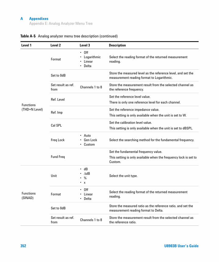
A Appendixes Appendix E: Analog Analyzer Menu Tree
Functions (THD+N Level)
Format
• Off• Logarithmic• Linear• Delta
Select the reading format of the returned measurement reading.
Set to 0dBStore the measured level as the reference level, and set the measurement reading format to Logarithmic.
Set result as ref. from
Channels 1 to 8Store the measurement result from the selected channel as the reference frequency.
Ref. LevelSet the reference level value.
There is only one reference level for each channel.
Ref. ImpSet the reference impedance value.
This setting is only available when the unit is set to W.
Cal SPLSet the calibration level value.
This setting is only available when the unit is set to dBSPL.
Freq Lock• Auto• Gen Lock• Custom
Select the searching method for the fundamental frequency.
Fund Freq
Set the fundamental frequency value.
This setting is only available when the frequency lock is set to Custom.
Functions (SINAD)
Unit
• dB• ΔdB• %• x
Select the unit type.
Format• Off• Linear• Delta
Select the reading format of the returned measurement reading.
Set to 0dBStore the measured ratio as the reference ratio, and set the measurement reading format to Delta.
Set result as ref. from
Channels 1 to 8Store the measurement result from the selected channel as the reference ratio.
Table A-5 Analog analyzer menu tree description (continued)
Level 1 Level 2 Level 3 Description
352 U8903B User’s Guide

Appendixes A Appendix E: Analog Analyzer Menu Tree
Functions (SINAD)
Ref. RatioSet the reference ratio value.
There is only one reference ratio for each channel.
Freq Lock• Auto• Gen Lock• Custom
Select the searching method for the fundamental frequency.
Fund Freq
Set the fundamental frequency value.
This setting is only available when the frequency lock is set to Custom.
Functions (THD Ratio)
Unit
• dB• ΔdB• %• x
Select the unit type.
Format• Off• Linear• Delta
Select the reading format of the returned measurement reading.
Set to 0dBStore the measured ratio as the reference ratio, and set the measurement reading format to Delta.
Set result as ref. from
Channels 1 to 8Store the measurement result from the selected channel as the reference ratio.
Ref. RatioSet the reference ratio value.
There is only one reference ratio for each channel.
Even Harmonic
• ALL• 2• 4• 6• 8
Display the even harmonics order selection.
Odd Harmonic
• ALL• 3• 5• 7• 9
Display the odd harmonics order selection.
Freq Lock• Auto• Gen Lock• Custom
Select the searching method for the fundamental frequency.
Table A-5 Analog analyzer menu tree description (continued)
Level 1 Level 2 Level 3 Description
U8903B User’s Guide 353

A Appendixes Appendix E: Analog Analyzer Menu Tree
Functions (THD Ratio)
Fund Freq
Set the fundamental frequency value.
This setting is only available when the frequency lock is set to Custom.
Functions (THD Level)
Unit
• dBg• dBm• dBr• dBu• dBV• W• V• ΔV• dBSPL• x
Select the unit type.
Format
• Off• Logarithmic• Linear• Delta
Select the reading format of the returned measurement reading.
Set to 0dBStore the measured level as the reference level, and set the measurement reading format to Logarithmic.
Set result as ref. from
Channels 1 to 8Store the measurement result from the selected channel as the reference frequency.
Ref. LevelSet the reference level value.
There is only one reference level for each channel.
Ref. ImpSet the reference impedance value.
This setting is only available when the unit is set to W.
Cal SPLSet the calibration level value.
This setting is only available when the unit is set to dBSPL.
Even Harmonic
• ALL• 2• 4• 6• 8
Select the even harmonics values.
Table A-5 Analog analyzer menu tree description (continued)
Level 1 Level 2 Level 3 Description
354 U8903B User’s Guide

Appendixes A Appendix E: Analog Analyzer Menu Tree
Functions (THD Level)
Odd Harmonic
• ALL• 3• 5• 7• 9
Select the odd harmonics values.
Freq Lock• Auto• Gen Lock• Custom
Select the searching method for the fundamental frequency.
Fund Freq
Set the fundamental frequency value.
This setting is only available when the frequency lock is set to Custom.
Functions (DFD60268 2nd/ DFD 60268 3rd/ DFD 60118 2nd/ DFD 60118 3rd)
Unit
• dB• ΔdB• %• x
Select the unit type.
Format• Off• Linear• Delta
Select the reading format of the returned measurement reading.
Set to 0dBStore the measured ratio as the reference ratio, and set the measurement reading format to Delta.
Set result as ref. from
Channels 1 to 8Store the measurement result from the selected channel as the reference ratio.
Ref. RatioSet the reference ratio value.
There is only one reference ratio for each channel.
Functions (SMPTE IMD)
Unit
• dB• ΔdB• %• x
Select the unit type.
Format• Off• Linear• Delta
Select the reading format of the returned measurement reading.
Set to 0dBStore the measured ratio as the reference ratio, and set the measurement reading format to Delta.
Table A-5 Analog analyzer menu tree description (continued)
Level 1 Level 2 Level 3 Description
U8903B User’s Guide 355

A Appendixes Appendix E: Analog Analyzer Menu Tree
Functions (SMPTE IMD)
Set result as ref. from
Channels 1 to 8Store the measurement result from the selected channel as the reference ratio.
Ref. RatioSet the reference ratio value.
There is only one reference ratio for each channel.
Freq Lock• Gen Lock• Custom
Select the searching method for the upper and lower frequencies.
Upper Freq
Set the upper frequency value.
This setting is only available when the frequency lock is set to Custom.
Lower Freq
Set the lower frequency value.
This setting is only available when the frequency lock is set to Custom.
Functions (SNR)
Unit
• dB• ΔdB• %• x
Select the unit type.
Format• Off• Linear• Delta
Select the reading format of the returned measurement reading.
Set to 0dBStore the measured ratio as the reference ratio, and set the measurement reading format to Delta.
Set result as ref. from
Channels 1 to 8Store the measurement result from the selected channel as the reference ratio.
Ref. RatioSet the reference ratio value.
There is only one reference ratio for each channel.
SNR Delay Set the SNR delay value.
Functions (SNR (Fast))
Unit
• dB• ΔdB• %• x
Select the unit type.
Table A-5 Analog analyzer menu tree description (continued)
Level 1 Level 2 Level 3 Description
356 U8903B User’s Guide

Appendixes A Appendix E: Analog Analyzer Menu Tree
Functions (SNR (Fast))
Format• Off• Linear• Delta
Select the reading format of the returned measurement reading.
Set to 0dBStore the measured ratio as the reference ratio, and set the measurement reading format to Delta.
Set result as ref. from
Channels 1 to 8Store the measurement result from the selected channel as the reference frequency.
Ref. RatioSet the reference ratio value.
There is only one reference ratio for each channel.
Freq Lock• Auto• Gen Lock• Custom
Select the searching method for the fundamental frequency.
Fund Freq
Set the fundamental frequency value.
This setting is only available when the frequency lock is set to Custom.
Harmonics Set the number of harmonics order to be removed.
Functions (Phase)
Ref. Channel Set the reference channel number.
Freq Lock• Auto• Gen Lock• Custom
Select the searching method for the fundamental frequency.
Fund Freq
Set the fundamental frequency value.
This setting is only available when the frequency lock is set to Custom.
Functions (X-Talk)
Ref. Channel Set the driven channel.
Unit
• dB• ΔdB• %• x
Select the unit type.
Format• Off• Linear• Delta
Select the reading format of the returned measurement reading.
Table A-5 Analog analyzer menu tree description (continued)
Level 1 Level 2 Level 3 Description
U8903B User’s Guide 357

A Appendixes Appendix E: Analog Analyzer Menu Tree
Functions (X-Talk)
Set to 0dBStore the measured ratio as the reference ratio, and set the measurement reading format to Delta.
Set result as ref. from
Channels 1 to 8Store the measurement result from the selected channel as the reference ratio.
Ref. RatioSet the reference ratio value.
There is only one reference ratio for each channel.
Freq Lock• Auto• Gen Lock• Custom
Select the searching method for the fundamental frequency.
Fund Freq
Set the fundamental frequency value.
This setting is only available when the frequency lock is set to Custom.
Filters Config
Clear Filters Clear all the filter settings.
LPF
• None• 2 kHz• 3 kHz• 5 kHz• 8 kHz• 10 kHz• 15 kHz• 20 kHz• 22 kHz• 30 kHz• 40 kHz• 50 kHz• 80 kHz• Custom
Select the low-pass filter.
Table A-5 Analog analyzer menu tree description (continued)
Level 1 Level 2 Level 3 Description
358 U8903B User’s Guide

Appendixes A Appendix E: Analog Analyzer Menu Tree
Filters Config
HPF
• None• 15 Hz• 20 Hz• 22 Hz• 30 Hz• 50 Hz• 70 Hz• 100 Hz• 200 Hz• 300 Hz• 400 Hz• Custom
Select the high-pass filter.
Weighting
• None• A• CCIR 1k• CCIR 2k• C-Message• CCITT• Custom
Select the weighting filter.
Deemphasis
• None• 50 μs• 75 μs• Custom
Select the filter de-emphasis value.
Notch Filter
State Enable or disable the notch filter.
Center FreqSet the frequency of the component to be removed from the input signal.
Bandwidth Set the bandwidth of the signal component to be removed.
Meas Config
Auto Range• On• Off
Enable or disable the auto range.
Range
• 140 V• 100 V• 32 V• 10 V• 3.2 V• 1 V• 320 mV
Select the input voltage range value.
This setting is only available when the auto range is disabled.
Table A-5 Analog analyzer menu tree description (continued)
Level 1 Level 2 Level 3 Description
U8903B User’s Guide 359

A Appendixes Appendix E: Analog Analyzer Menu Tree
Meas Config
Sample Size
• 2048• 4096• 8192• 16384• 32768• 65536• 131072• 262144• 524288• 1M• 2M
Select the sample size.
Average Points 1 to 50Set the number of measurement readings to be used for the moving average calculation.
Src Channel
Select the internal generator channel as the reference channel used in the following situations.
• For the result calculation in unit dBg.• For the frequencies searching algorithm when the
frequency lock is set to Gen Lock.
Trigger Source• Free Run• External
Select the trigger source
Trigger Edge• Rising• Falling
Select the trigger edge type.
Input Config
Connector• UnBal• Bal• Loopback
Select the input connector type.
Impedance
• 100 kΩ (for UnBal)
• 200 kΩ (for Bal)
• 600 Ω• 300 Ω
Select the input impedance value.
This setting is only available when the input connector is set to UnBal or Bal.
Table A-5 Analog analyzer menu tree description (continued)
Level 1 Level 2 Level 3 Description
360 U8903B User’s Guide
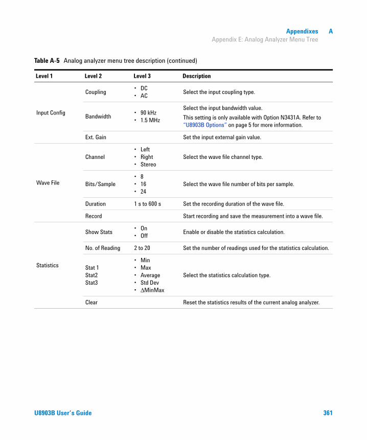
Appendixes A Appendix E: Analog Analyzer Menu Tree
Input Config
Coupling• DC• AC
Select the input coupling type.
Bandwidth• 90 kHz• 1.5 MHz
Select the input bandwidth value.
This setting is only available with Option N3431A. Refer to “U8903B Options” on page 5 for more information.
Ext. Gain Set the input external gain value.
Wave File
Channel• Left• Right• Stereo
Select the wave file channel type.
Bits/Sample• 8• 16• 24
Select the wave file number of bits per sample.
Duration 1 s to 600 s Set the recording duration of the wave file.
Record Start recording and save the measurement into a wave file.
Statistics
Show Stats• On• Off
Enable or disable the statistics calculation.
No. of Reading 2 to 20 Set the number of readings used for the statistics calculation.
Stat 1 Stat2 Stat3
• Min• Max• Average• Std Dev• ΔMinMax
Select the statistics calculation type.
Clear Reset the statistics results of the current analog analyzer.
Table A-5 Analog analyzer menu tree description (continued)
Level 1 Level 2 Level 3 Description
U8903B User’s Guide 361

A Appendixes Appendix F: Graph Analysis Menu Tree
Appendix F: Graph Analysis Menu Tree
Table A-6 Graph analysis menu tree description
Level 1 Level 2 Level 3 Description
Analysis Mode
• Frequency• Phase• Time• PSD
Select the graph analysis mode to be plotted on the current graph panel.
This setting is not available when the graph analysis display option is Harmonics.
Harm Settings
Active Channel AA1 to AA8
Select the active channel.
This setting is only available when the graph analysis display option is Harmonics.
AA2: Analog Analyzer channel 2
Odd Harmonic
• ALL• 3• 5• 7• 9
Select the odd harmonics values.
This setting is only available when the graph analysis display option is Harmonics.
Even Harmonic
• ALL• 2• 4• 6• 8
Select the even harmonics values.
This setting is only available when the graph analysis display option is Harmonics.
Display• Harmonics• THD
Select the harmonics display option.
This setting is only available when the graph analysis display option is Harmonics.
THD Unit• dB• %
Select the unit for THD measurements.
This setting is only available when the graph analysis display option is Harmonics.
Graph Settings Active Channel AA1 to AA8Select the available active channel.
AA2: Analog Analyzer channel 2
362 U8903B User’s Guide

Appendixes A Appendix F: Graph Analysis Menu Tree
Graph Settings
Sample Size
• 2048• 4096• 8192• 16384• 32768• 65536• 131072• 262144• 524288• 1M• 2M
Select the graph sample size value.
Window
• Rectangular• Hanning• Blackman• Rife-Vincent• Rife-Vincent 3• Hamming• Flat Top• Kaiser
Select the window function to be applied to the data before the FFT process.
Sync Avg 1 to 64Set the number of samples to be acquired and averaged before the FFT process is performed.
Hold
• None• Average• Min• Max
Select the type of hold to be performed after the FFT process.
Axis Settings
Axis• Primary• Secondary
Select the active axis to be configured.
Enabled• On• Off
Enable or disable the axis settings.
This setting is only available when the axis type is secondary. If the axis type is primary, this setting is always set to On.
Left Set the left axis limit value.
Right Set the right axis limit value.
Table A-6 Graph analysis menu tree description (continued)
Level 1 Level 2 Level 3 Description
U8903B User’s Guide 363

A Appendixes Appendix F: Graph Analysis Menu Tree
Axis Settings
SpanSet the total X-axis span or total range to be monitored in the graph.
Center Set the X-axis center point in the graph.
Top Set the top axis limit value.
Bottom Set the bottom axis limit value.
X-Scale• Linear• Log
Select the X-axis scale type.
Y-Scale• Linear• Log
Select the Y-axis scale type.
Trace Settings
Active Trace 1 to 8 Select the active trace channel.
SourceSelect data source of the active trace from the available channels, traces, files, and memory.
Enabled• On• Off
Enable or disable the active trace data.
Memory
Save To Memory the active trace to the memory buffer.
Load From Memory
Load a trace from the memory buffer into the active trace.
Clear Memory Clear the trace from the memory buffer.
Math
Apply Math
Apply the corresponding math function to the trace data or turn off the math function.
• On• Off
Function
Select the math function to be applied on the active trace.
• f(Source)• f(Source) + x• f(Source) - x• f(Source) * x• f(Source) / x
Variable Set the x value in the selected math function.
Table A-6 Graph analysis menu tree description (continued)
Level 1 Level 2 Level 3 Description
364 U8903B User’s Guide

Appendixes A Appendix F: Graph Analysis Menu Tree
Trace Settings
Unit
• V• dBV• dBu• W• dBm• dBSPL
Select the trace unit type.
Persistence
Persist Enable or disable the persistence on the active trace.
Persist Count
Set the number of previous sets of trace data to be displayed in the graph before they are removed.
This setting is only available when persistence is enabled.
Axis• Primary• Secondary
Attach the active trace to the primary or secondary axis.
Color
• Yellow• Cyan• White• Pink• Green• Orange• Red• Purple
Select the color of the active trace.
Display Option
• Graph• Data Table• Marker Table• Statistics• Harmonics• Signal Analysis
Select the graph analysis display option.
Running mode• Continuous• Single
Select the graph analysis running mode.
Measurement
Enabled• On• Off
Enable or disable the measurements in the graph.
Measurement 1 Channel Select the desired channel to perform the measurement.
Function NoSelect the function to be displayed based on the function number (1 to 4).
Table A-6 Graph analysis menu tree description (continued)
Level 1 Level 2 Level 3 Description
U8903B User’s Guide 365
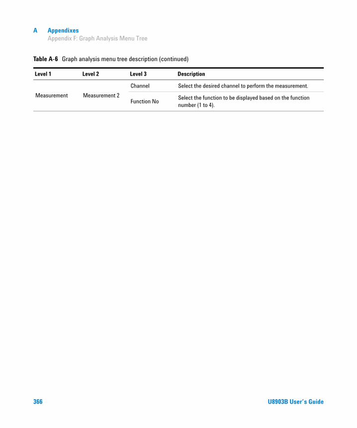
A Appendixes Appendix F: Graph Analysis Menu Tree
Measurement Measurement 2
Channel Select the desired channel to perform the measurement.
Function NoSelect the function to be displayed based on the function number (1 to 4).
Table A-6 Graph analysis menu tree description (continued)
Level 1 Level 2 Level 3 Description
366 U8903B User’s Guide

Appendixes A Appendix G: Sweep Function Menu Tree
Appendix G: Sweep Function Menu Tree
Table A-7 Sweep function menu tree description
Level 1 Level 2 Level 3 Level 4 Description
Legacy Status• On• Off
Enable or disable the legacy sweep.
Parameter
Select the sweep parameter type.
The parameter selection depends on the waveform type set at the analog generator.
Points Settings
Spacing• Log• Linear• Custom
Select the spacing type.
Unit
• Vrms• dBV• Vp• Vpp• dBm• dBu• dBSPL
Select the sweep unit.
This setting is only available when the sweep parameter is amplitude.
StartSet the sweep start value. This setting is only available when the sweep spacing is Log or Linear.
StopSet the sweep stop value. This setting is only available when the sweep spacing is Log or Linear.
StepSet the sweep step value. This setting is only available when the sweep spacing is Log or Linear.
PointsSet the sweep points value. This setting is only available when the sweep spacing is Log or Linear.
Edit PointsRefer to “Edit points” for the edit points menu tree.
U8903B User’s Guide 367
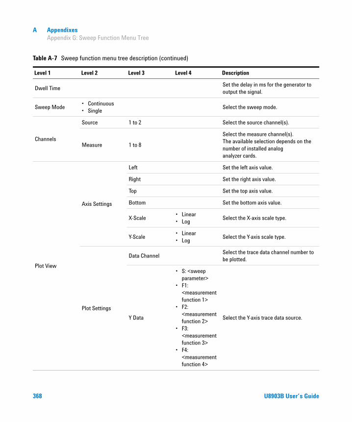
A Appendixes Appendix G: Sweep Function Menu Tree
Dwell TimeSet the delay in ms for the generator to output the signal.
Sweep Mode• Continuous• Single
Select the sweep mode.
Channels
Source 1 to 2 Select the source channel(s).
Measure 1 to 8
Select the measure channel(s). The available selection depends on the number of installed analog analyzer cards.
Plot View
Axis Settings
Left Set the left axis value.
Right Set the right axis value.
Top Set the top axis value.
Bottom Set the bottom axis value.
X-Scale• Linear• Log
Select the X-axis scale type.
Y-Scale• Linear• Log
Select the Y-axis scale type.
Plot Settings
Data ChannelSelect the trace data channel number to be plotted.
Y Data
• S: <sweep parameter>
• F1: <measurement function 1>
• F2: <measurement function 2>
• F3: <measurement function 3>
• F4: <measurement function 4>
Select the Y-axis trace data source.
Table A-7 Sweep function menu tree description (continued)
Level 1 Level 2 Level 3 Level 4 Description
368 U8903B User’s Guide
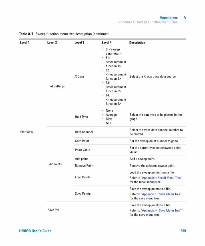
Appendixes A Appendix G: Sweep Function Menu Tree
Plot View
Plot Settings
X Data
• S: <sweep parameter>
• F1: <measurement function 1>
• F2: <measurement function 2>
• F3: <measurement function 3>
• F4: <measurement function 4>
Select the X-axis trace data source.
Hold Type
• None• Average• Max• Min
Select the data type to be plotted in the graph.
Edit points
Data ChannelSelect the trace data channel number to be plotted.
Goto Point Set the sweep point number to go to.
Point ValueSet the currently selected sweep point value.
Add point Add a sweep point.
Remove Point Remove the selected sweep point.
Load Points
Load the sweep points from a file.
Refer to “Appendix I: Recall Menu Tree” for the recall menu tree.
Save Points
Save the sweep points to a file.
Refer to “Appendix H: Save Menu Tree” for the save menu tree.
Save Pts
Save the sweep points to a file.
Refer to “Appendix H: Save Menu Tree” for the save menu tree.
Table A-7 Sweep function menu tree description (continued)
Level 1 Level 2 Level 3 Level 4 Description
U8903B User’s Guide 369

A Appendixes Appendix H: Save Menu Tree
Appendix H: Save Menu Tree
Table A-8 Save menu tree description
Level 1 Level 2 Description
Save Save to a file.
Type Select the file type to be displayed on the current directory.
Rename OK Set the file name and select OK to rename the file name.
Copy or Move
Mark Mark the selected file.
Copy Marked To Folder
Copy the marked file to the selected folder.
Move Marked To Folder
Move the marked file to the selected folder.
Delete Delete the selected file.
New Folder OK Set the new folder name and select OK to create a new folder.
370 U8903B User’s Guide

Appendixes A Appendix I: Recall Menu Tree
Appendix I: Recall Menu Tree
Table A-9 Recall menu tree description
Level 1 Level 2 Description
Recall Recall a saved file.
Type Select the file type to be displayed on the current directory.
Rename OK Set the file name and select OK to rename the file name.
Copy or Move
Mark Mark the selected file.
Copy Marked To Folder
Copy the marked file to the selected folder.
Move Marked To Folder
Move the marked file to the selected folder.
Delete Delete the selected file.
New Folder OK Set the new folder name and select OK to create a new folder.
U8903B User’s Guide 371
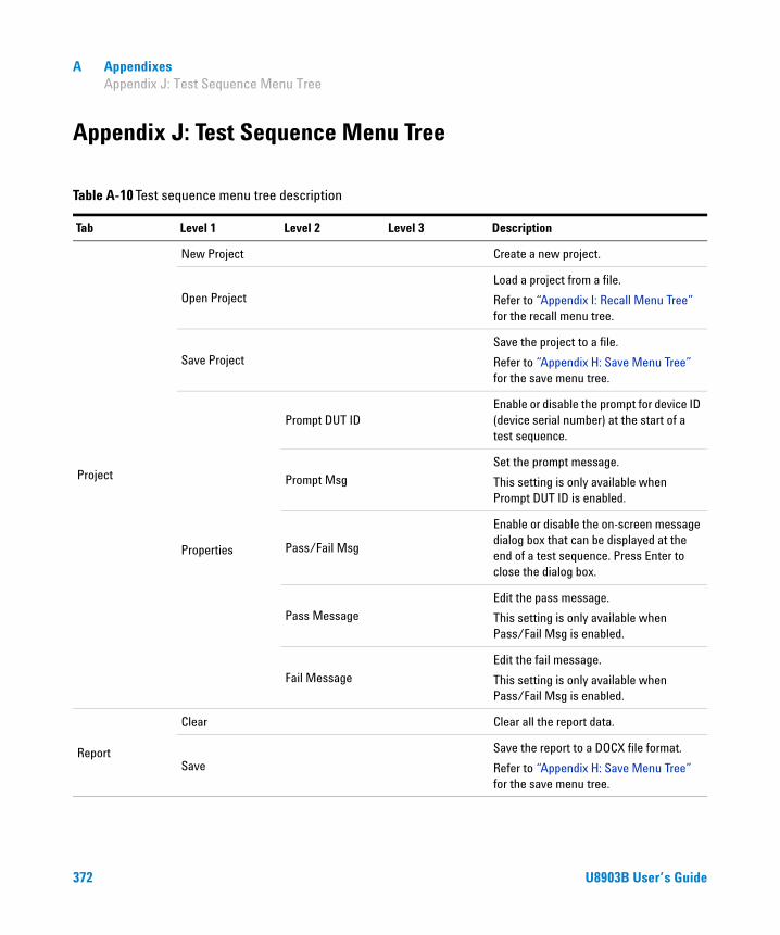
A Appendixes Appendix J: Test Sequence Menu Tree
Appendix J: Test Sequence Menu Tree
Table A-10 Test sequence menu tree description
Tab Level 1 Level 2 Level 3 Description
Project
New Project Create a new project.
Open Project
Load a project from a file.
Refer to “Appendix I: Recall Menu Tree” for the recall menu tree.
Save Project
Save the project to a file.
Refer to “Appendix H: Save Menu Tree” for the save menu tree.
Properties
Prompt DUT IDEnable or disable the prompt for device ID (device serial number) at the start of a test sequence.
Prompt Msg
Set the prompt message.
This setting is only available when Prompt DUT ID is enabled.
Pass/Fail Msg
Enable or disable the on-screen message dialog box that can be displayed at the end of a test sequence. Press Enter to close the dialog box.
Pass Message
Edit the pass message.
This setting is only available when Pass/Fail Msg is enabled.
Fail Message
Edit the fail message.
This setting is only available when Pass/Fail Msg is enabled.
Report
Clear Clear all the report data.
Save
Save the report to a DOCX file format.
Refer to “Appendix H: Save Menu Tree” for the save menu tree.
372 U8903B User’s Guide

Appendixes A Appendix J: Test Sequence Menu Tree
Report Properties
Auto Save• Enable• Disable
Enable or disable saving the report automatically at the end of a test sequence.
Format• Docx• Html
Select the report file format to be saved.
Name Option• Timestamp• Numeric• Prompt
Select the naming convention of the file name for the automatically saved report.
Prefix Set the prefix for the file name.
Location
SelectSelect the folder for the automatically saved report.
New FolderCreate a new folder at the current directory or folder.
Test
StatusEnable or disable the selected test sequence.
Add Test Sequence
• New• Saved
Add a new test sequence.
Delete Test Sequence
Delete the selected test sequence.
Save
Save the test sequence to a file.
Refer to “Appendix H: Save Menu Tree” for the save menu tree.
Edit
Move Move the selected test sequence.
Copy Copy the selected test sequence.
PastePaste a copied test sequence after the selected test sequence.
Properties Name Set the test sequence name.
Table A-10 Test sequence menu tree description (continued)
Tab Level 1 Level 2 Level 3 Description
U8903B User’s Guide 373

A Appendixes Appendix J: Test Sequence Menu Tree
IO Configuration
Add Measurement
Add measurements to the selected test sequence.
Refer to “Add Measurement” on page 379 for the list of test measurements.
Edit PastePaste a copied measurement after the IO configuration. The IO Configuration cannot be moved or copied.
Settings: Output Configuration
Channels• None (External)• 1• 2
Select the number of output channels in use.
Connector
• Bal• UnBal• Com• IEC60268
Select the output connector type.
Impedance
For Bal, Com, and IEC60268
• 600 Ω• 100 Ω• 40 ΩFor UnBal
• 600 Ω• 50 Ω• 20 Ω
Select the output impedance value.
IEC60268• Pin 2• Pin 3
Select the additional 10 Ω output series resistance for pin 2 or 3 of the XLR connector in the common IEC 60268 configuration.
This setting is only available when the output connector type is set to IEC 60268.
Ground• Float• Ground
Select the grounding type.
Max Voltage Set the maximum voltage.
Reference ImpedanceSet the reference impedance for the unit conversion of dBm measurements.
Table A-10 Test sequence menu tree description (continued)
Tab Level 1 Level 2 Level 3 Description
374 U8903B User’s Guide

Appendixes A Appendix J: Test Sequence Menu Tree
IO Configuration
Settings: Input Configuration
ChannelsSelect the number of input channels in use.
Connector• UnBal• Bal• Loopback
Select the input connector type.
Impedance
• 100 kΩ (for Unbalanced)
• 200 kΩ (for Balanced)
• 600 Ω• 300 Ω
Select the input impedance value.
This setting is only available when Connector is set to UnBal or Bal.
Coupling• DC• AC
Select the input coupling type.
Bandwidth• 90 kHz• 1.5 MHz
Select the input bandwidth value.
This setting is only available with Option N3431A.
Reference
Voltage Set the input voltage value.
Ratio Set the input ratio value.
Frequency Set the input frequency value.
Impedance Set the input impedance value.
Sound level Set the input sound level value.
Calibrator level Set the input calibrator level value.
Properties
Name Rename the IO configuration.
Sub-Steps: RunIO Configuration
Add Sub-Step
Add sub-step to the list.
• Delay• Prompt• Sent SCPI
EditMove the RunIO Configuration sub-step in the list.
Table A-10 Test sequence menu tree description (continued)
Tab Level 1 Level 2 Level 3 Description
U8903B User’s Guide 375

A Appendixes Appendix J: Test Sequence Menu Tree
IO Configuration Properties
Sub-Steps: Delay
Status Enable or disable the delay sub-step.
Add Sub-Step
Add sub-step to the list.
• Delay• Prompt• Sent SCPI
Delete Sub-Step Delete the selected sub-step.
EditMove or copy the selected sub-step, or paste a copied sub-step after the selected sub-step.
Settings
Configure the delay sub-step settings.
• Delay Set the delay time in seconds.
Properties Rename the delay sub-step name.
Sub-Steps: Prompt
Status Enable or disable the prompt sub-step.
Add Sub-Step
Add sub-step to the list.
• Delay• Prompt• Sent SCPI
Delete Sub-Step Delete the selected sub-step.
EditMove or copy the selected sub-step, or paste a copied sub-step after the selected sub-step.
Table A-10 Test sequence menu tree description (continued)
Tab Level 1 Level 2 Level 3 Description
376 U8903B User’s Guide

Appendixes A Appendix J: Test Sequence Menu Tree
IO Configuration Properties
Sub-Steps: Prompt
Settings
• Message Set the prompt message at the lower half of the main display.
• Prompt Icon Select the prompt icon to be displayed.• None• Hand• Question• Exclamation• Asterisk
• Dialog Settings Add additional settings to the prompt window.• Timeout• Cancel Button
• Timeout Set the prompt timeout value in seconds.
Properties Set the prompt sub-step name.
Sub-Steps: Send SCPI
Status Enable or disable the send SCPI sub-step.
Add Sub-Step
Add sub-step to the list.
• Delay• Prompt• Sent SCPI
Delete Sub-Step Delete the selected sub-step.
EditMove or copy the selected sub-step, or paste a copied sub-step after the selected sub-step.
Table A-10 Test sequence menu tree description (continued)
Tab Level 1 Level 2 Level 3 Description
U8903B User’s Guide 377

A Appendixes Appendix J: Test Sequence Menu Tree
IO Configuration PropertiesSub-Steps: Send SCPI
Settings
• GPIB Address Select the desired GPIB address.
• SCPI Commands• Edit
Set the SCPI commands at the lower half of the main display.
• Import Load the SCPI commands from a file. Refer to “Appendix I: Recall Menu Tree” for the recall menu tree.
• Progress Msg Set the optional text message that will be displayed on a dialog box for the time length set in Delay.
• Delay Set the delay time length after the SCPI command(s) is issued.
Properties Set the prompt sub-step name.
Measurement StatusEnable or disable the selected measurement.
Table A-10 Test sequence menu tree description (continued)
Tab Level 1 Level 2 Level 3 Description
378 U8903B User’s Guide
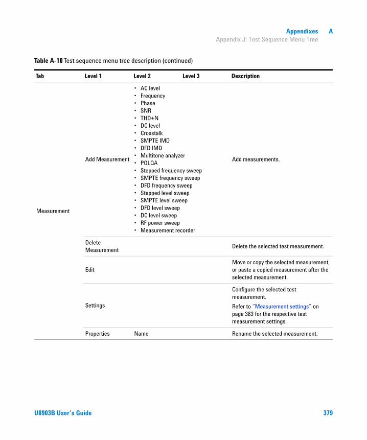
Appendixes A Appendix J: Test Sequence Menu Tree
Measurement
Add Measurement
• AC level• Frequency• Phase• SNR• THD+N• DC level• Crosstalk• SMPTE IMD• DFD IMD• Multitone analyzer• POLQA• Stepped frequency sweep• SMPTE frequency sweep• DFD frequency sweep• Stepped level sweep• SMPTE level sweep• DFD level sweep• DC level sweep• RF power sweep• Measurement recorder
Add measurements.
Delete Measurement
Delete the selected test measurement.
EditMove or copy the selected measurement, or paste a copied measurement after the selected measurement.
Settings
Configure the selected test measurement.
Refer to “Measurement settings” on page 383 for the respective test measurement settings.
Properties Name Rename the selected measurement.
Table A-10 Test sequence menu tree description (continued)
Tab Level 1 Level 2 Level 3 Description
U8903B User’s Guide 379

A Appendixes Appendix J: Test Sequence Menu Tree
Measurement Properties
Sub-Steps: RunIO Configuration
Add Sub-Step
Add sub-step to the list.
• Delay• Prompt• Sent SCPI
EditMove the RunIO Configuration sub-step in the list.
Sub-Steps: Delay
Status Enable or disable the delay sub-step.
Add Sub-Step
Add sub-step to the list.
• Delay• Prompt• Sent SCPI
Delete Sub-Step Delete the selected sub-step.
EditMove or copy the selected sub-step, or paste a copied sub-step after the selected sub-step.
Settings
Configure the delay sub-step settings.
• Delay Set the delay time in seconds.
Properties Rename the delay sub-step name.
Sub-Steps: Prompt
Status Enable or disable the prompt sub-step.
Add Sub-Step
Add sub-step to the list.
• Delay• Prompt• Sent SCPI
Delete Sub-Step Delete the selected sub-step.
EditMove or copy the selected sub-step, or paste a copied sub-step after the selected sub-step.
Table A-10 Test sequence menu tree description (continued)
Tab Level 1 Level 2 Level 3 Description
380 U8903B User’s Guide

Appendixes A Appendix J: Test Sequence Menu Tree
Measurement Properties
Sub-Steps: Prompt
Settings
• Message Set the prompt message at the lower half of the main display.
• Prompt Icon Select the prompt icon to be displayed.• None• Hand• Question• Exclamation• Asterisk
• Dialog Settings Add additional settings to the prompt window.• Timeout• Cancel Button
• Timeout Set the prompt timeout value in seconds.
Properties Set the prompt sub-step name.
Sub-Steps: Send SCPI
Status Enable or disable the send SCPI sub-step.
Add Sub-Step
Add sub-step to the list.
• Delay• Prompt• Sent SCPI
Delete Sub-Step Delete the selected sub-step.
EditMove or copy the selected sub-step, or paste a copied sub-step after the selected sub-step.
Table A-10 Test sequence menu tree description (continued)
Tab Level 1 Level 2 Level 3 Description
U8903B User’s Guide 381
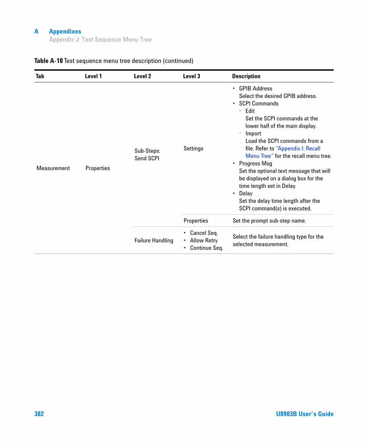
A Appendixes Appendix J: Test Sequence Menu Tree
Measurement Properties
Sub-Steps: Send SCPI
Settings
• GPIB Address Select the desired GPIB address.
• SCPI Commands• Edit
Set the SCPI commands at the lower half of the main display.
• Import Load the SCPI commands from a file. Refer to “Appendix I: Recall Menu Tree” for the recall menu tree.
• Progress Msg Set the optional text message that will be displayed on a dialog box for the time length set in Delay.
• Delay Set the delay time length after the SCPI command(s) is executed.
Properties Set the prompt sub-step name.
Failure Handling• Cancel Seq.• Allow Retry• Continue Seq.
Select the failure handling type for the selected measurement.
Table A-10 Test sequence menu tree description (continued)
Tab Level 1 Level 2 Level 3 Description
382 U8903B User’s Guide

Appendixes A Appendix J: Test Sequence Menu Tree
Measurement settings
AC level
Table A-11 Measurement settings > AC Level menu tree description
Tab Level 1 Level 2 Level 3 Description
AC Level (Signal Generation)
Waveform
• Sine• Variable Phase• Square• Arbitrary
Select the waveform type.
Output Select the output channel.
Waveform Config
Track 1st Ch• Enable• Disable
Enable or disable the tracking of the first channel.
Frequency Set the frequency value.
Amplitude Set the amplitude value.
DC Offset Set the DC offset value.
Phase->1st ChSet the phase value. This setting is only available when channel 2 is selected.
AC Level (Signal Analysis)
Detector• RMS• Pk-Pk
Select the AC level detector type.
LPF
• None• 2 kHz• 3 kHz• 5 kHz• 8 kHz• 10 kHz• 15 kHz• 20 kHz• 22 kHz• 30 kHz• 40 kHz• 50 kHz• 80 kHz• Custom
Select the low-pass filter.
U8903B User’s Guide 383

A Appendixes Appendix J: Test Sequence Menu Tree
Frequency
AC Level (Signal Analysis)
Sample Size
• 2048• 4096• 8192• 16384• 32768• 65536• 131072• 262144• 524288• 1M• 2M
Select the number of samples to be acquired for the measurement.
Input Range
Auto Range• On• Off
Enable or disable the auto input range.
Track 1st Ch• Enable• Disable
Enable or disable the tracking of the first channel.
Voltage Range Set the input voltage range.
• AC Level• Gain
Refer to “Bar chart” on page 426 for the bar chart menu tree.
Table A-11 Measurement settings > AC Level menu tree description (continued)
Tab Level 1 Level 2 Level 3 Description
Table A-12 Measurement settings > Frequency menu tree description
Tab Level 1 Level 2 Level 3 Description
Frequency (Signal Generation)
Waveform
• Sine• Variable Phase• Square• Arbitrary
Select the waveform type.
Output Select the output channel.
Waveform Config
Track 1st Ch• Enable• Disable
Enable or disable the tracking of the first channel.
Frequency Set the frequency value.
Amplitude Set the amplitude value.
384 U8903B User’s Guide

Appendixes A Appendix J: Test Sequence Menu Tree
Frequency (Signal Generation)
Waveform Config
DC Offset Set the DC offset value.
Phase->1st ChSet the phase value. This setting is only available when channel 2 is selected.
Frequency (Signal Analysis)
Sample Size
• 2048• 4096• 8192• 16384• 32768• 65536• 131072• 262144• 524288• 1M• 2M
Select the number of samples to be acquired for the measurement.
Input Range
Auto Range• On• Off
Enable or disable the auto input range.
Track 1st Ch• Enable• Disable
Enable or disable the tracking of the first channel.
Voltage Range Set the input voltage range.
FrequencyRefer to “Bar chart” on page 426 for the bar chart menu tree.
Table A-12 Measurement settings > Frequency menu tree description (continued)
Tab Level 1 Level 2 Level 3 Description
U8903B User’s Guide 385

A Appendixes Appendix J: Test Sequence Menu Tree
Phase
Table A-13 Measurement settings > Phase menu tree description
Tab Level 1 Level 2 Level 3 Description
Phase (Signal Generation)
Waveform
• Sine• Variable Phase• Square• Arbitrary
Select the waveform type.
Output Select the output channel.
Waveform Config Track 1st Ch• Enable• Disable
Enable or disable the tracking of the first channel.
Phase (Signal Generation)
Waveform Config
Frequency Set the frequency value.
Amplitude Set the amplitude value.
DC Offset Set the DC offset value.
Phase->1st ChSet the phase value. This setting is only available when channel 2 is selected.
Phase (Signal Analysis)
Ref Channel Set the reference channel number.
Sample Size
• 2048• 4096• 8192• 16384• 32768• 65536• 131072• 262144• 524288• 1M• 2M
Select the number of samples to be acquired for the measurement.
Input RangeTrack 1st Ch
• Enable• Disable
Enable or disable the tracking of the first channel.
Voltage Range Set the input voltage range.
PhaseRefer to “Bar chart” on page 426 for the bar chart menu tree.
386 U8903B User’s Guide
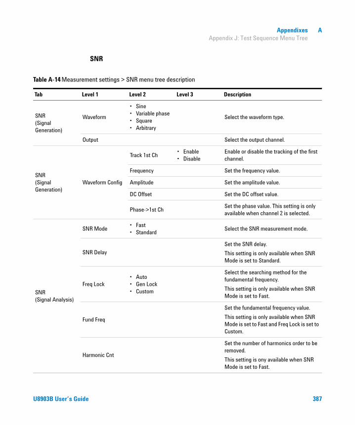
Appendixes A Appendix J: Test Sequence Menu Tree
SNR
Table A-14 Measurement settings > SNR menu tree description
Tab Level 1 Level 2 Level 3 Description
SNR (Signal Generation)
Waveform
• Sine• Variable phase• Square• Arbitrary
Select the waveform type.
Output Select the output channel.
SNR (Signal Generation)
Waveform Config
Track 1st Ch• Enable• Disable
Enable or disable the tracking of the first channel.
Frequency Set the frequency value.
Amplitude Set the amplitude value.
DC Offset Set the DC offset value.
Phase->1st ChSet the phase value. This setting is only available when channel 2 is selected.
SNR (Signal Analysis)
SNR Mode• Fast• Standard
Select the SNR measurement mode.
SNR Delay
Set the SNR delay.
This setting is only available when SNR Mode is set to Standard.
Freq Lock• Auto• Gen Lock• Custom
Select the searching method for the fundamental frequency.
This setting is only available when SNR Mode is set to Fast.
Fund Freq
Set the fundamental frequency value.
This setting is only available when SNR Mode is set to Fast and Freq Lock is set to Custom.
Harmonic Cnt
Set the number of harmonics order to be removed.
This setting is ony available when SNR Mode is set to Fast.
U8903B User’s Guide 387

A Appendixes Appendix J: Test Sequence Menu Tree
SNR (Signal Analysis)
LPF
• None• 2 kHz• 3 kHz• 5 kHz• 8 kHz• 10 kHz• 15 kHz• 20 kHz• 22 kHz• 30 kHz• 40 kHz• 50 kHz• 80 kHz• Custom
Select the low-pass filter.
HPF
• None• 15 Hz• 20 Hz• 22 Hz• 30 Hz• 50 Hz• 70 Hz• 100 Hz• 200 Hz• 300 Hz• 400 Hz• Custom
Select the high-pass filter.
Weighting
• None• A• CCIR 1k• CCIR 2k• CCITT• C-Message• Custom
Select the weighting filter.
Deemphasis
• None• 50 μs• 75 μs• Custom
Select the de-emphasis filter.
Table A-14 Measurement settings > SNR menu tree description (continued)
Tab Level 1 Level 2 Level 3 Description
388 U8903B User’s Guide

Appendixes A Appendix J: Test Sequence Menu Tree
THD+N
SNR (Signal Analysis)
Sample Size
• 2048• 4096• 8192• 16384• 32768• 65536• 131072• 262144• 524288• 1M• 2M
Select the number of samples to be acquired for the measurement.
Input Range
Auto Range• On• Off
Enable or disable the auto input range.
Track 1st Ch• Enable• Disable
Enable or disable the tracking of the first channel.
Voltage Range Set the input voltage range.
SNRRefer to “Bar chart” on page 426 for the bar chart menu tree.
Table A-14 Measurement settings > SNR menu tree description (continued)
Tab Level 1 Level 2 Level 3 Description
Table A-15 Measurement settings > THD+N menu tree description
Tab Level 1 Level 2 Level 3 Description
THD+N (Signal Generation)
Waveform
• Sine• Variable phase• Square• Arbitrary
Select the waveform type.
Output Select the output channel.
Waveform Config
Track 1st Ch• Enable• Disable
Enable or disable the tracking of the first channel.
Frequency Set the frequency value.
Amplitude Set the amplitude value.
U8903B User’s Guide 389
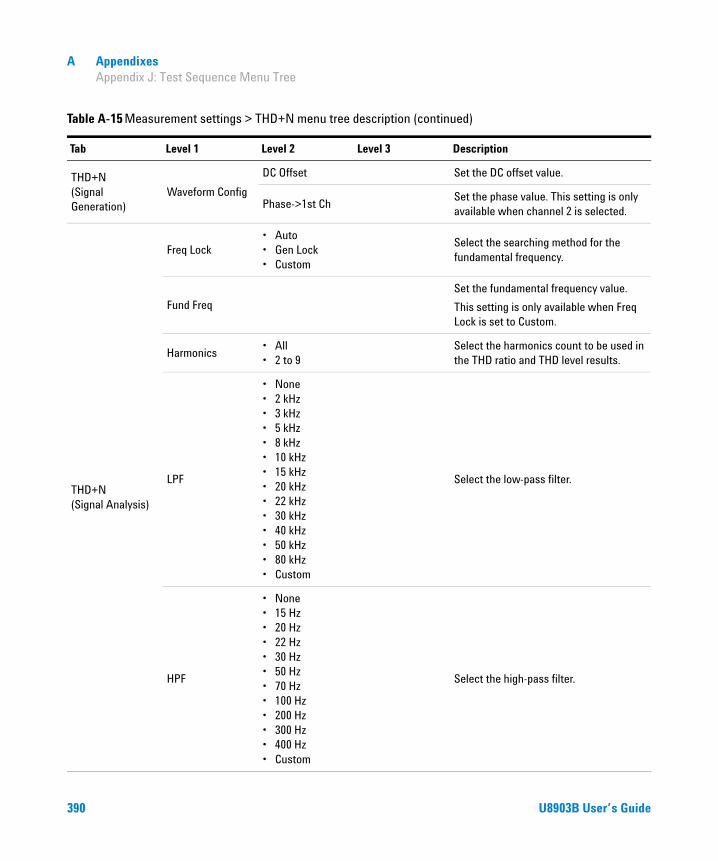
A Appendixes Appendix J: Test Sequence Menu Tree
THD+N (Signal Generation)
Waveform Config
DC Offset Set the DC offset value.
Phase->1st ChSet the phase value. This setting is only available when channel 2 is selected.
THD+N (Signal Analysis)
Freq Lock• Auto• Gen Lock• Custom
Select the searching method for the fundamental frequency.
Fund Freq
Set the fundamental frequency value.
This setting is only available when Freq Lock is set to Custom.
Harmonics• All• 2 to 9
Select the harmonics count to be used in the THD ratio and THD level results.
LPF
• None• 2 kHz• 3 kHz• 5 kHz• 8 kHz• 10 kHz• 15 kHz• 20 kHz• 22 kHz• 30 kHz• 40 kHz• 50 kHz• 80 kHz• Custom
Select the low-pass filter.
HPF
• None• 15 Hz• 20 Hz• 22 Hz• 30 Hz• 50 Hz• 70 Hz• 100 Hz• 200 Hz• 300 Hz• 400 Hz• Custom
Select the high-pass filter.
Table A-15 Measurement settings > THD+N menu tree description (continued)
Tab Level 1 Level 2 Level 3 Description
390 U8903B User’s Guide
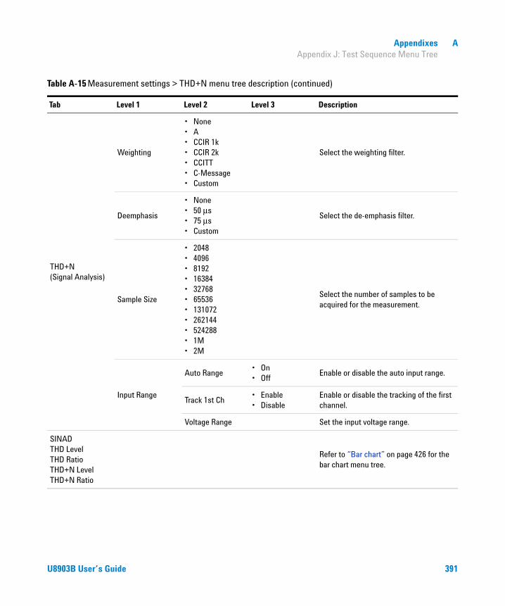
Appendixes A Appendix J: Test Sequence Menu Tree
THD+N (Signal Analysis)
Weighting
• None• A• CCIR 1k• CCIR 2k• CCITT• C-Message• Custom
Select the weighting filter.
Deemphasis
• None• 50 μs• 75 μs• Custom
Select the de-emphasis filter.
Sample Size
• 2048• 4096• 8192• 16384• 32768• 65536• 131072• 262144• 524288• 1M• 2M
Select the number of samples to be acquired for the measurement.
Input Range
Auto Range• On• Off
Enable or disable the auto input range.
Track 1st Ch• Enable• Disable
Enable or disable the tracking of the first channel.
Voltage Range Set the input voltage range.
SINAD THD Level THD Ratio THD+N Level THD+N Ratio
Refer to “Bar chart” on page 426 for the bar chart menu tree.
Table A-15 Measurement settings > THD+N menu tree description (continued)
Tab Level 1 Level 2 Level 3 Description
U8903B User’s Guide 391

A Appendixes Appendix J: Test Sequence Menu Tree
DC level
Table A-16 Measurement settings > DC Level menu tree description
Tab Level 1 Level 2 Level 3 Description
DC Level (Signal Generation)
Waveform• Sine• Arbitrary
Select the waveform type.
Output Select the output channel.
Waveform Config
Track 1st Ch• Enable• Disable
Enable or disable the tracking of the first channel.
Frequency Set the frequency value.
Amplitude Set the amplitude value.
DC Offset Set the DC offset value.
DC Level (Signal Analysis)
Sample Size
• 2048• 4096• 8192• 16384• 32768• 65536• 131072• 262144• 524288• 1M• 2M
Select the number of samples to be acquired for the measurement.
Input Range
Auto Range• On• Off
Enable or disable the auto input range.
Track 1st Ch• Enable• Disable
Enable or disable the tracking of the first channel.
Voltage Range Set the input voltage range.
DC LevelRefer to “Bar chart” on page 426 for the bar chart menu tree.
392 U8903B User’s Guide
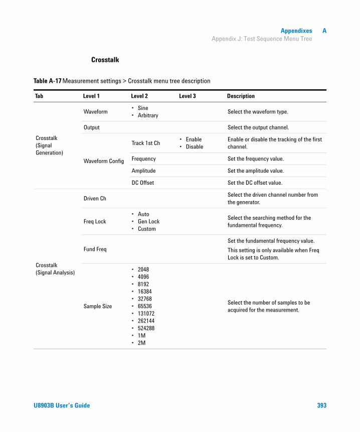
Appendixes A Appendix J: Test Sequence Menu Tree
Crosstalk
Table A-17 Measurement settings > Crosstalk menu tree description
Tab Level 1 Level 2 Level 3 Description
Crosstalk (Signal Generation)
Waveform• Sine• Arbitrary
Select the waveform type.
Output Select the output channel.
Waveform Config
Track 1st Ch• Enable• Disable
Enable or disable the tracking of the first channel.
Frequency Set the frequency value.
Amplitude Set the amplitude value.
DC Offset Set the DC offset value.
Crosstalk (Signal Analysis)
Driven ChSelect the driven channel number from the generator.
Freq Lock• Auto• Gen Lock• Custom
Select the searching method for the fundamental frequency.
Fund Freq
Set the fundamental frequency value.
This setting is only available when Freq Lock is set to Custom.
Sample Size
• 2048• 4096• 8192• 16384• 32768• 65536• 131072• 262144• 524288• 1M• 2M
Select the number of samples to be acquired for the measurement.
U8903B User’s Guide 393
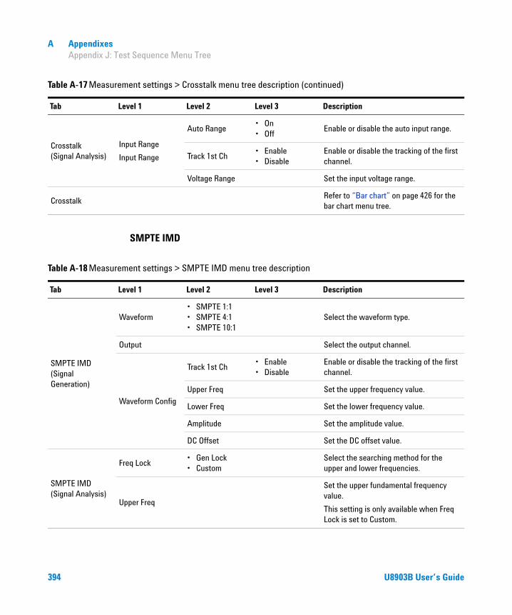
A Appendixes Appendix J: Test Sequence Menu Tree
SMPTE IMD
Crosstalk (Signal Analysis)
Input Range
Input Range
Auto Range• On• Off
Enable or disable the auto input range.
Track 1st Ch• Enable• Disable
Enable or disable the tracking of the first channel.
Voltage Range Set the input voltage range.
CrosstalkRefer to “Bar chart” on page 426 for the bar chart menu tree.
Table A-17 Measurement settings > Crosstalk menu tree description (continued)
Tab Level 1 Level 2 Level 3 Description
Table A-18 Measurement settings > SMPTE IMD menu tree description
Tab Level 1 Level 2 Level 3 Description
SMPTE IMD (Signal Generation)
Waveform• SMPTE 1:1• SMPTE 4:1• SMPTE 10:1
Select the waveform type.
Output Select the output channel.
Waveform Config
Track 1st Ch• Enable• Disable
Enable or disable the tracking of the first channel.
Upper Freq Set the upper frequency value.
Lower Freq Set the lower frequency value.
Amplitude Set the amplitude value.
DC Offset Set the DC offset value.
SMPTE IMD (Signal Analysis)
Freq Lock• Gen Lock• Custom
Select the searching method for the upper and lower frequencies.
Upper Freq
Set the upper fundamental frequency value.
This setting is only available when Freq Lock is set to Custom.
394 U8903B User’s Guide

Appendixes A Appendix J: Test Sequence Menu Tree
DFD IMD
SMPTE IMD (Signal Analysis)
Lower Freq
Set the lower fundamental frequency value.
This setting is only available when Freq Lock is set to Custom.
Sample Size
• 2048• 4096• 8192• 16384• 32768• 65536• 131072• 262144• 524288• 1M• 2M
Select the number of samples to be acquired for the measurement.
Input Range
Auto Range• On• Off
Enable or disable the auto input range.
Track 1st Ch• Enable• Disable
Enable or disable the tracking of the first channel.
Voltage Range Set the input voltage range.
SMPTE RatioRefer to “Bar chart” on page 426 for the bar chart menu tree.
Table A-18 Measurement settings > SMPTE IMD menu tree description (continued)
Tab Level 1 Level 2 Level 3 Description
Table A-19 Measurement settings > DFD IMD menu tree description
Tab Level 1 Level 2 Level 3 Description
DFD IMD (Signal Generation)
Waveform• IEC60118• IEC60268
Select the waveform type.
Output Select the output channel.
U8903B User’s Guide 395

A Appendixes Appendix J: Test Sequence Menu Tree
DFD IMD (Signal Generation)
Waveform Config
Track 1st Ch• Enable• Disable
Enable or disable the tracking of the first channel.
Upper Freq Set the upper frequency value.
Center Freq Set the center frequency value.
Diff Freq Set the difference frequency value.
Amplitude Set the amplitude value.
DC Offset Set the DC offset value.
DFD IMD (Signal Analysis)
DFD order• 2nd• 3rd
Select the distortion order to be measured.
Sample Size
• 2048• 4096• 8192• 16384• 32768• 65536• 131072• 262144• 524288• 1M• 2M
Select the number of samples to be acquired for the measurement.
Input Range
Auto Range• On• Off
Enable or disable the auto input range.
Track 1st Ch• Enable• Disable
Enable or disable the tracking of the first channel.
Voltage Range Set the input voltage range.
DFD RatioRefer to “Bar chart” on page 426 for the bar chart menu tree.
Table A-19 Measurement settings > DFD IMD menu tree description (continued)
Tab Level 1 Level 2 Level 3 Description
396 U8903B User’s Guide

Appendixes A Appendix J: Test Sequence Menu Tree
Multitone analyzer
Table A-20 Measurement settings > Multitone Analyzer menu tree description
Tab Level 1 Level 2 Level 3 Description
Multitone (Signal Generation)
Output Select the output channel.
Waveform ConfigTrack 1st Ch
• Enable• Disable
Enable or disable the tracking of the first channel.
Amplitude Set the total amplitude value.
Tones Config
Start FreqSet the lowest frequency in the multitone waveform which is usually the frequency of the first tone.
Stop FreqSet the highest frequency in the multitone waveform which is usually the frequency for the last tone.
Spacing• Linear• Log• Custom
Select the frequency spacing between the tones.
TonesSet the number of signal frequency components.
Length
• 1024• 2048• 4096• 8192• 16384• 32768• 65536
Select the waveform length value.
Phase Dist• Zero• Random• Custom
Select the phase distribution of each tone.
Ampl. Mode• Zero• Custom
Select the amplitude ratio of each tone.
Optimization• On• Off
Enable or disable the crest factor optimization.
U8903B User’s Guide 397

A Appendixes Appendix J: Test Sequence Menu Tree
Multitone (Signal Generation)
Tones Config
Edit Tones
Frequency Set the frequency value.
Amplitude Set the amplitude value.
Phase Set the phase value.
Add Above Add a tone above the selected tone.
Add Below Add a tone below the selected tone.
Remove Remove the selected tone.
Clear All Remove all the tones in the list.
Apply Settings
Apply the settings to calculate the crest factor of the multitone signal each time you change the settings in the Tones Config menu.
Active ChannelSet the active channel for the absolute amplitude for each tone to be displayed in a table.
Multitone (Signal Analysis)
Input RangeTrack 1st Ch
• Enable• Disable
Enable or disable the tracking of the first channel.
Voltage Range Set the input voltage range.
• Spectrum• Waveform• Level• Gain
Refer to “Graph” on page 427 for the graph menu tree.
• Max Tone Level• Min Tone Level• TD+N Level• TD+N Ratio• Tone Level
Refer to “Bar chart” on page 426 for the bar chart menu tree.
Table A-20 Measurement settings > Multitone Analyzer menu tree description (continued)
Tab Level 1 Level 2 Level 3 Description
398 U8903B User’s Guide

Appendixes A Appendix J: Test Sequence Menu Tree
Stepped frequency sweep
Table A-21 Measurement settings > Stepped Frequency Sweep menu tree description
Tab Level 1 Level 2 Level 3 Description
Stepped Frequency Sweep (Signal Generation)
Output Select the output channel.
Sweep Config
StartSet the start value for the sweep parameter.
StopSet the stop value for the sweep parameter.
SpacingSelect Log, Linear, or Custom for the sweep spacing.
Points Set the number of sweep points.
Step SizeSet the step size for linear spacing. This setting is only available when spacing is set to Linear.
Dwell Time Set the delay between the sweep points.
Edit Points
Point No Set the point number.
Point Value Set the point value.
Insert Point Above Insert a point above the selected point.
Insert Point Below Insert a point below the selected point.
Remove Point Remove the selected point.
Clear Clear all points.
Reverse Order Reverse the order of the points.
Sort Sort the points in ascending order.
Load Points
Load points from a file.
Refer to “Appendix I: Recall Menu Tree” for the recall menu tree.
Save Points
Save the points to a file.
Refer to “Appendix H: Save Menu Tree” for the save menu tree.
U8903B User’s Guide 399

A Appendixes Appendix J: Test Sequence Menu Tree
Stepped Frequency Sweep (Signal Generation)
Waveform Config
Track 1st Ch• Enable• Disable
Enable or disable the tracking of the first channel.
Amplitude Set the amplitude value.
DC Offset Set the DC offset value.
Stepped Frequency Sweep (Signal Analysis)
Ref Channel Set the reference channel number.
Harmonics• All• 2 to 9
Select the harmonics count to be used in the THD ratio and THD level results.
LPF
• None• 2 kHz• 3 kHz• 5 kHz• 8 kHz• 10 kHz• 15 kHz• 20 kHz• 22 kHz• 30 kHz• 40 kHz• 50 kHz• 80 kHz• Custom
Select the low-pass filter.
HPF
• None• 15 Hz• 20 Hz• 22 Hz• 30 Hz• 50 Hz• 70 Hz• 100 Hz• 200 Hz• 300 Hz• 400 Hz• Custom
Select the high-pass filter.
Table A-21 Measurement settings > Stepped Frequency Sweep menu tree description (continued)
Tab Level 1 Level 2 Level 3 Description
400 U8903B User’s Guide

Appendixes A Appendix J: Test Sequence Menu Tree
Stepped Frequency Sweep (Signal Analysis)
Weighting
• None• A• CCIR 1k• CCIR 2k• CCITT• C-Message• Custom
Select the weighting filter.
Deemphasis
• None• 50 μs• 75 μs• Custom
Select the de-emphasis filter.
Sample Size
• 2048• 4096• 8192• 16384• 32768• 65536• 131072• 262144• 524288• 1M• 2M
Select the number of samples to be acquired for the measurement.
Input Range
Auto Range• On• Off
Enable or disable the auto input range.
Track 1st Ch• Enable• Disable
Enable or disable the tracking of the first channel.
Voltage Range Set the input voltage range.
• AC Level• Gain• Phase• THD Ratio• THD Level• THD+N Ratio• THD+N Level• SINAD
Refer to “Graph” on page 427 for the graph menu tree.
Table A-21 Measurement settings > Stepped Frequency Sweep menu tree description (continued)
Tab Level 1 Level 2 Level 3 Description
U8903B User’s Guide 401

A Appendixes Appendix J: Test Sequence Menu Tree
SMPTE frequency sweep
Table A-22 Measurement settings > SMPTE Frequency Sweep menu tree description
Tab Level 1 Level 2 Level 3 Description
SMPTE Frequency Sweep (Signal Generation)
Waveform• SMPTE 1:1• SMPTE 4:1• SMPTE 10:1
Select the waveform type.
Output Select the output channel.
Sweep Config
Swept• Upper Freq• Lowe Freq
Select the sweep parameter.
StartSet the start value for the sweep parameter.
StopSet the stop value for the sweep parameter.
SpacingSelect Log, Linear, or Custom for the sweep spacing.
Points Set the number of sweep points.
Step SizeSet the step size for linear spacing. This setting is only available when spacing is set to Linear.
Dwell Time Set the delay between the sweep points.
Edit Points
Point No Set the point number.
Point Value Set the point value.
Insert Point Above Insert a point above the selected point.
Insert Point Below Insert a point below the selected point.
Remove Point Remove the selected point.
Clear Clear all points.
Reverse Order Reverse the order of the points.
Sort Sort the points in ascending order.
402 U8903B User’s Guide

Appendixes A Appendix J: Test Sequence Menu Tree
SMPTE Frequency Sweep (Signal Generation)
Sweep Config Edit Points
Load Points
Load points from a file.
Refer to “Appendix I: Recall Menu Tree” for the recall menu tree.
Save Points
Save the points to a file.
Refer to “Appendix H: Save Menu Tree” for the save menu tree.
Waveform Config
Track 1st Ch• Enable• Disable
Enable or disable the tracking of the first channel.
Upper Freq Set the upper frequency value.
Lower Freq Set the lower frequency value.
Amplitude Set the amplitude value.
DC Offset Set the DC offset value.
SMPTE Frequency Sweep (Signal Analysis)
Sample Size
• 2048• 4096• 8192• 16384• 32768• 65536• 131072• 262144• 524288• 1M• 2M
Select the number of samples to be acquired for the measurement.
Input Range
Auto Range• On• Off
Enable or disable the auto input range.
Track 1st Ch• Enable• Disable
Enable or disable the tracking of the first channel.
Voltage Range Set the input voltage range.
SMPTE RatioRefer to “Graph” on page 427 for the graph menu tree.
Table A-22 Measurement settings > SMPTE Frequency Sweep menu tree description (continued)
Tab Level 1 Level 2 Level 3 Description
U8903B User’s Guide 403
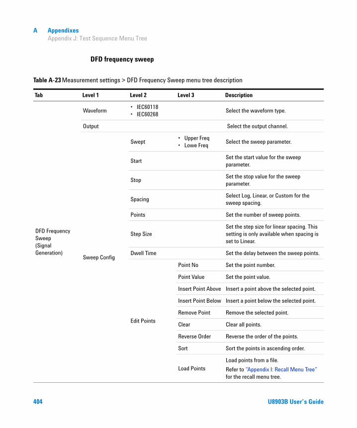
A Appendixes Appendix J: Test Sequence Menu Tree
DFD frequency sweep
Table A-23 Measurement settings > DFD Frequency Sweep menu tree description
Tab Level 1 Level 2 Level 3 Description
DFD Frequency Sweep (Signal Generation)
Waveform• IEC60118• IEC60268
Select the waveform type.
Output Select the output channel.
Sweep Config
Swept• Upper Freq• Lowe Freq
Select the sweep parameter.
StartSet the start value for the sweep parameter.
StopSet the stop value for the sweep parameter.
SpacingSelect Log, Linear, or Custom for the sweep spacing.
Points Set the number of sweep points.
Step SizeSet the step size for linear spacing. This setting is only available when spacing is set to Linear.
Dwell Time Set the delay between the sweep points.
Edit Points
Point No Set the point number.
Point Value Set the point value.
Insert Point Above Insert a point above the selected point.
Insert Point Below Insert a point below the selected point.
Remove Point Remove the selected point.
Clear Clear all points.
Reverse Order Reverse the order of the points.
Sort Sort the points in ascending order.
Load Points
Load points from a file.
Refer to “Appendix I: Recall Menu Tree” for the recall menu tree.
404 U8903B User’s Guide
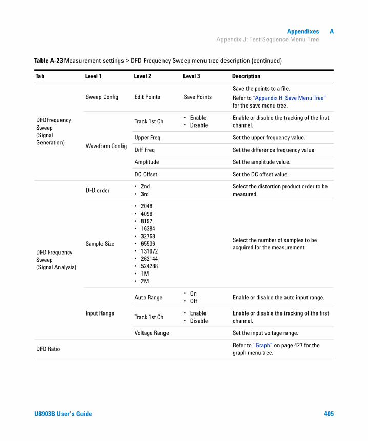
Appendixes A Appendix J: Test Sequence Menu Tree
DFDFrequency Sweep (Signal Generation)
Sweep Config Edit Points Save Points
Save the points to a file.
Refer to “Appendix H: Save Menu Tree” for the save menu tree.
Waveform Config
Track 1st Ch• Enable• Disable
Enable or disable the tracking of the first channel.
Upper Freq Set the upper frequency value.
Diff Freq Set the difference frequency value.
Amplitude Set the amplitude value.
DC Offset Set the DC offset value.
DFD Frequency Sweep (Signal Analysis)
DFD order• 2nd• 3rd
Select the distortion product order to be measured.
Sample Size
• 2048• 4096• 8192• 16384• 32768• 65536• 131072• 262144• 524288• 1M• 2M
Select the number of samples to be acquired for the measurement.
Input Range
Auto Range• On• Off
Enable or disable the auto input range.
Track 1st Ch• Enable• Disable
Enable or disable the tracking of the first channel.
Voltage Range Set the input voltage range.
DFD RatioRefer to “Graph” on page 427 for the graph menu tree.
Table A-23 Measurement settings > DFD Frequency Sweep menu tree description (continued)
Tab Level 1 Level 2 Level 3 Description
U8903B User’s Guide 405
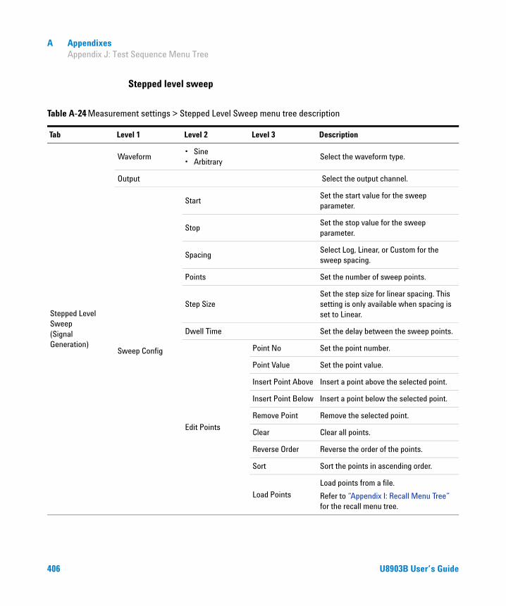
A Appendixes Appendix J: Test Sequence Menu Tree
Stepped level sweep
Table A-24 Measurement settings > Stepped Level Sweep menu tree description
Tab Level 1 Level 2 Level 3 Description
Stepped Level Sweep (Signal Generation)
Waveform• Sine• Arbitrary
Select the waveform type.
Output Select the output channel.
Sweep Config
StartSet the start value for the sweep parameter.
StopSet the stop value for the sweep parameter.
SpacingSelect Log, Linear, or Custom for the sweep spacing.
Points Set the number of sweep points.
Step SizeSet the step size for linear spacing. This setting is only available when spacing is set to Linear.
Dwell Time Set the delay between the sweep points.
Edit Points
Point No Set the point number.
Point Value Set the point value.
Insert Point Above Insert a point above the selected point.
Insert Point Below Insert a point below the selected point.
Remove Point Remove the selected point.
Clear Clear all points.
Reverse Order Reverse the order of the points.
Sort Sort the points in ascending order.
Load Points
Load points from a file.
Refer to “Appendix I: Recall Menu Tree” for the recall menu tree.
406 U8903B User’s Guide

Appendixes A Appendix J: Test Sequence Menu Tree
Stepped Level Sweep (Signal Generation)
Sweep Config Edit Points Save Points
Save the points to a file.
Refer to “Appendix H: Save Menu Tree” for the save menu tree.
Waveform Config
Track 1st Ch• Enable• Disable
Enable or disable the tracking of the first channel.
Frequency Set the frequency value.
DC Offset Set the DC offset value.
Stepped Level Sweep (Signal Analysis)
Freq Lock• Auto• Gen Lock• Custom
Select the searching method for the fundamental frequency.
Fund FreqSet the fundamental frequency value. This setting is only available when Freq Lock is set to Custom.
LPF
• None• 2 kHz• 3 kHz• 5 kHz• 8 kHz• 10 kHz• 15 kHz• 20 kHz• 22 kHz• 30 kHz• 40 kHz• 50 kHz• 80 kHz• Custom
Select the low-pass filter.
Table A-24 Measurement settings > Stepped Level Sweep menu tree description (continued)
Tab Level 1 Level 2 Level 3 Description
U8903B User’s Guide 407

A Appendixes Appendix J: Test Sequence Menu Tree
Stepped Level Sweep (Signal Analysis)
HPF
• None• 15 Hz• 20 Hz• 22 Hz• 30 Hz• 50 Hz• 70 Hz• 100 Hz• 200 Hz• 300 Hz• 400 Hz• Custom
Select the high-pass filter.
Weighting
• None• A• CCIR 1k• CCIR 2k• CCITT• C-Message• Custom
Select the weighting filter.
Deemphasis
• None• 50 μs• 75 μs• Custom
Select the de-emphasis filter.
Sample Size
• 2048• 4096• 8192• 16384• 32768• 65536• 131072• 262144• 524288• 1M• 2M
Select the number of samples to be acquired for the measurement.
Table A-24 Measurement settings > Stepped Level Sweep menu tree description (continued)
Tab Level 1 Level 2 Level 3 Description
408 U8903B User’s Guide

Appendixes A Appendix J: Test Sequence Menu Tree
SMPTE level sweep
Stepped Level Sweep (Signal Analysis)
Input Range
Auto Range• On• Off
Enable or disable the auto input range.
Track 1st Ch• Enable• Disable
Enable or disable the tracking of the first channel.
Voltage Range Set the input voltage range.
• AC Level• Gain• THD Ratio• THD Level• THD Ratio Vs Measured Amplitude• THD Level Vs Measured Amplitude• THD+N ratio• THD+N Level• THD+N Ratio Vs Measured Amplitude• THD+N Level Vs Measured Amplitude• SINAD
Refer to “Graph” on page 427 for the graph menu tree.
Table A-24 Measurement settings > Stepped Level Sweep menu tree description (continued)
Tab Level 1 Level 2 Level 3 Description
Table A-25 Measurement settings > SMPTE Level Sweep menu tree description
Tab Level 1 Level 2 Level 3 Description
SMPTE Level Sweep (Signal Generation)
Waveform• SMPTE 1:1• SMPTE 4:1• SMPTE 10:1
Select the waveform type.
Output Select the output channel.
Sweep Config
StartSet the start value for the sweep parameter.
StopSet the stop value for the sweep parameter.
SpacingSelect Log, Linear, or Custom for the sweep spacing.
Points Set the number of sweep points.
U8903B User’s Guide 409

A Appendixes Appendix J: Test Sequence Menu Tree
SMPTE Level Sweep (Signal Generation)
Sweep Config
Step SizeSet the step size for linear spacing. This setting is only available when spacing is set to Linear.
Dwell Time Set the delay between the sweep points.
Edit Points
Point No Set the point number.
Point Value Set the point value.
Insert Point Above Insert a point above the selected point.
Insert Point Below Insert a point below the selected point.
Remove Point Remove the selected point.
Clear Clear all points.
Reverse Order Reverse the order of the points.
Sort Sort the points in ascending order.
Load Points
Load points from a file.
Refer to “Appendix I: Recall Menu Tree” for the recall menu tree.
Save Points
Save the points to a file.
Refer to “Appendix H: Save Menu Tree” for the save menu tree.
Waveform Config
Track 1st Ch• Enable• Disable
Enable or disable the tracking of the first channel.
Upper Freq Set the upper frequency value.
Lower Freq Set the lower frequency value.
DC Offset Set the DC offset value.
SMPTE Level Sweep (Signal Analysis)
Freq Lock• Gen Lock• Custom
Select the searching method for the upper and lower frequencies.
Upper FreqSet the upper fundamental frequency value. This setting is only available when Freq Lock is set to Custom.
Table A-25 Measurement settings > SMPTE Level Sweep menu tree description (continued)
Tab Level 1 Level 2 Level 3 Description
410 U8903B User’s Guide

Appendixes A Appendix J: Test Sequence Menu Tree
DFD level sweep
SMPTE Level Sweep (Signal Analysis)
Lower FreqSet the lower fundamental frequency value. This setting is only available when Freq Lock is set to Custom.
Sample Size
• 2048• 4096• 8192• 16384• 32768• 65536• 131072• 262144• 524288• 1M• 2M
Select the number of samples to be acquired for the measurement.
Input Range
Auto Range• On• Off
Enable or disable the auto input range.
Track 1st Ch• Enable• Disable
Enable or disable the tracking of the first channel.
Voltage Range Set the input voltage range.
• SMPTE Ratio• SMPTE Ratio Vs Measured Amplitude
Refer to “Graph” on page 427 for the graph menu tree.
Table A-25 Measurement settings > SMPTE Level Sweep menu tree description (continued)
Tab Level 1 Level 2 Level 3 Description
Table A-26 Measurement settings > DFD Level Sweep menu tree description
Tab Level 1 Level 2 Level 3 Description
DFD Level Sweep (Signal Generation)
Waveform• IEC60118• IEC60268
Select the waveform type.
Output Select the output channel.
Sweep Config StartSet the start value for the sweep parameter.
U8903B User’s Guide 411
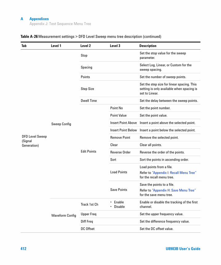
A Appendixes Appendix J: Test Sequence Menu Tree
DFD Level Sweep (Signal Generation)
Sweep Config
StopSet the stop value for the sweep parameter.
SpacingSelect Log, Linear, or Custom for the sweep spacing.
Points Set the number of sweep points.
Step SizeSet the step size for linear spacing. This setting is only available when spacing is set to Linear.
Dwell Time Set the delay between the sweep points.
Edit Points
Point No Set the point number.
Point Value Set the point value.
Insert Point Above Insert a point above the selected point.
Insert Point Below Insert a point below the selected point.
Remove Point Remove the selected point.
Clear Clear all points.
Reverse Order Reverse the order of the points.
Sort Sort the points in ascending order.
Load Points
Load points from a file.
Refer to “Appendix I: Recall Menu Tree” for the recall menu tree.
Save Points
Save the points to a file.
Refer to “Appendix H: Save Menu Tree” for the save menu tree.
Waveform Config
Track 1st Ch• Enable• Disable
Enable or disable the tracking of the first channel.
Upper Freq Set the upper frequency value.
Diff Freq Set the difference frequency value.
DC Offset Set the DC offset value.
Table A-26 Measurement settings > DFD Level Sweep menu tree description (continued)
Tab Level 1 Level 2 Level 3 Description
412 U8903B User’s Guide
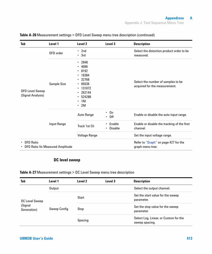
Appendixes A Appendix J: Test Sequence Menu Tree
DC level sweep
DFD Level Sweep (Signal Analysis)
DFD order• 2nd• 3rd
Select the distortion product order to be measured.
Sample Size
• 2048• 4096• 8192• 16384• 32768• 65536• 131072• 262144• 524288• 1M• 2M
Select the number of samples to be acquired for the measurement.
Input Range
Auto Range• On• Off
Enable or disable the auto input range.
Track 1st Ch• Enable• Disable
Enable or disable the tracking of the first channel.
Voltage Range Set the input voltage range.
• DFD Ratio• DFD Ratio Vs Measured Amplitude
Refer to “Graph” on page 427 for the graph menu tree.
Table A-26 Measurement settings > DFD Level Sweep menu tree description (continued)
Tab Level 1 Level 2 Level 3 Description
Table A-27 Measurement settings > DC Level Sweep menu tree description
Tab Level 1 Level 2 Level 3 Description
DC Level Sweep (Signal Generation)
Output Select the output channel.
Sweep Config
StartSet the start value for the sweep parameter.
StopSet the stop value for the sweep parameter.
SpacingSelect Log, Linear, or Custom for the sweep spacing.
U8903B User’s Guide 413

A Appendixes Appendix J: Test Sequence Menu Tree
DC Level Sweep (Signal Generation)
Sweep Config
Points Set the number of sweep points.
Step SizeSet the step size for linear spacing. This setting is only available when spacing is set to Linear.
Dwell Time Set the delay between the sweep points.
Edit Points
Point No Set the point number.
Point Value Set the point value.
Insert Point Above Insert a point above the selected point.
Insert Point Below Insert a point below the selected point.
Remove Point Remove the selected point.
Clear Clear all points.
Reverse Order Reverse the order of the points.
Sort Sort the points in ascending order.
Load Points
Load points from a file.
Refer to “Appendix I: Recall Menu Tree” for the recall menu tree.
Save Points
Save the points to a file.
Refer to “Appendix H: Save Menu Tree” for the save menu tree.
Table A-27 Measurement settings > DC Level Sweep menu tree description (continued)
Tab Level 1 Level 2 Level 3 Description
414 U8903B User’s Guide

Appendixes A Appendix J: Test Sequence Menu Tree
DC Level Sweep (Signal Analysis)
LPF
• None• 2 kHz• 3 kHz• 5 kHz• 8 kHz• 10 kHz• 15 kHz• 20 kHz• 22 kHz• 30 kHz• 40 kHz• 50 kHz• 80 kHz• Custom
Select the low-pass filter.
HPF
• None• 15 Hz• 20 Hz• 22 Hz• 30 Hz• 50 Hz• 70 Hz• 100 Hz• 200 Hz• 300 Hz• 400 Hz• Custom
Select the high-pass filter.
Weighting
• None• A• CCIR 1k• CCIR 2k• CCITT• C-Message• Custom
Select the weighting filter.
Deemphasis
• None• 50 μs• 75 μs• Custom
Select the de-emphasis filter.
Table A-27 Measurement settings > DC Level Sweep menu tree description (continued)
Tab Level 1 Level 2 Level 3 Description
U8903B User’s Guide 415

A Appendixes Appendix J: Test Sequence Menu Tree
RF power sweep
DC Level Sweep (Signal Analysis)
Sample Size
• 2048• 4096• 8192• 16384• 32768• 65536• 131072• 262144• 524288• 1M• 2M
Select the number of samples to be acquired for the measurement.
Input Range
Auto Range• On• Off
Enable or disable the auto input range.
Track 1st Ch• Enable• Disable
Enable or disable the tracking of the first channel.
Voltage Range Set the input voltage range.
DC LevelRefer to “Graph” on page 427 for the graph menu tree.
Table A-27 Measurement settings > DC Level Sweep menu tree description (continued)
Tab Level 1 Level 2 Level 3 Description
Table A-28 Measurement settings > RF Power Sweep menu tree description
Tab Level 1 Level 2 Level 3 Description
RF Power Sweep (Signal Generation)
Ext. Instrument• Agilent E4438C• Other
Set the signal generator model.
GPIB addressSet the GPIB address for the connected signal generator.
Start Power Set the sweep start RF power.
Stop Power Set the sweep stop RF power.
Coarse Step Set the coarse step size.
Fine Step Set the fine step size.
416 U8903B User’s Guide

Appendixes A Appendix J: Test Sequence Menu Tree
RF Power Sweep (Signal Generation)
Dwell TimeSet the delay between each measured SINAD in seconds.
Init InstrumentEnable or disable the U8903B to send SCPI commands to initialize the connected signal generator.
FM Frequency
Set the RF signal output frequency.
This setting is only available if Ext. Instrument is set to Agilent E4438C and the Init Instrument is enabled.
FM Deviation
Set the RF signal frequency modulation deviation.
This setting is only available if Ext. Instrument is set to Agilent E4438C and the Init Instrument is enabled.
FM Rate
Set the RF signal internal frequency modulation rate.
This setting is only available if Ext. Instrument is set to Agilent E4438C and the Init Instrument is enabled
Init SCPI
Set the SCPI commands that initialize the connected signal generator. You can set the SCPI command directly or load from a file.
This setting is only available if Ext. Instrument is set to Other and the Init Instrument is enabled.
Output Power SCPI
Set the SCPI command that adjusts the RF power of the connected signal generator.
RF Power Sweep (Signal Analysis)
Meas Channel Set the measured channel number.
Target SINADSet the target SINAD value measured from the Meas Channel.
Freq Lock• Auto• Custom
Select the searching method for the fundamental frequency.
Table A-28 Measurement settings > RF Power Sweep menu tree description (continued)
Tab Level 1 Level 2 Level 3 Description
U8903B User’s Guide 417

A Appendixes Appendix J: Test Sequence Menu Tree
RF Power Sweep (Signal Analysis)
Fund Freq
Set the fundamental frequency value.
This setting is only available when Freq Lock is set to Custom.
LPF
• None• 2 kHz• 3 kHz• 5 kHz• 8 kHz• 10 kHz• 15 kHz• 20 kHz• 22 kHz• 30 kHz• 40 kHz• 50 kHz• 80 kHz• Custom
Select the low-pass filter.
HPF
• None• 15 Hz• 20 Hz• 22 Hz• 30 Hz• 50 Hz• 70 Hz• 100 Hz• 200 Hz• 300 Hz• 400 Hz• Custom
Select the high-pass filter.
Weighting
• None• A• CCIR 1k• CCIR 2k• CCITT• C-Message• Custom
Select the weighting filter.
Table A-28 Measurement settings > RF Power Sweep menu tree description (continued)
Tab Level 1 Level 2 Level 3 Description
418 U8903B User’s Guide

Appendixes A Appendix J: Test Sequence Menu Tree
RF Power Sweep (Signal Analysis)
Deemphasis
• None• 50 μs• 75 μs• Custom
Select the de-emphasis filter.
Average PointsSet the number of measurement readings to be used for the average calculation.
Sample Size
• 2048• 4096• 8192• 16384• 32768• 65536• 131072• 262144• 524288• 1M• 2M
Select the number of samples to be acquired for the measurement.
Input Range
Auto Range• On• Off
Enable or disable the auto input range.
Track 1st Ch• Enable• Disable
Enable or disable the tracking of the first channel.
Voltage Range Set the input voltage range.
SINAD Vs RF PowerRefer to “Graph” on page 427 for the graph menu tree.
Table A-28 Measurement settings > RF Power Sweep menu tree description (continued)
Tab Level 1 Level 2 Level 3 Description
U8903B User’s Guide 419

A Appendixes Appendix J: Test Sequence Menu Tree
Measurement recorder
Table A-29 Measurement settings > Measurement Recorder menu tree description
Tab Level 1 Level 2 Level 3 Description
Measurement Recorder (Signal Generation)
Waveform
• Sine• Variable Phase• Square• Arbitrary
Select the waveform type.
Output Select the output channel.
Waveform Config
Track 1st Ch• Enable• Disable
Enable or disable the tracking of the first channel.
Frequency Set the frequency value.
Amplitude Set the amplitude value.
DC Offset Set the DC offset value.
Measurement Recorder (Signal Analysis)
DurationSet the length of the measurement record,
Ref Channel Set the reference channel number.
Freq Lock• Auto• Gen Lock• Custom
Select the searching method for the fundamental frequency.
Fund Freq
Set the fundamental frequency value.
This setting is only available when Freq Lock is set to Custom.
420 U8903B User’s Guide
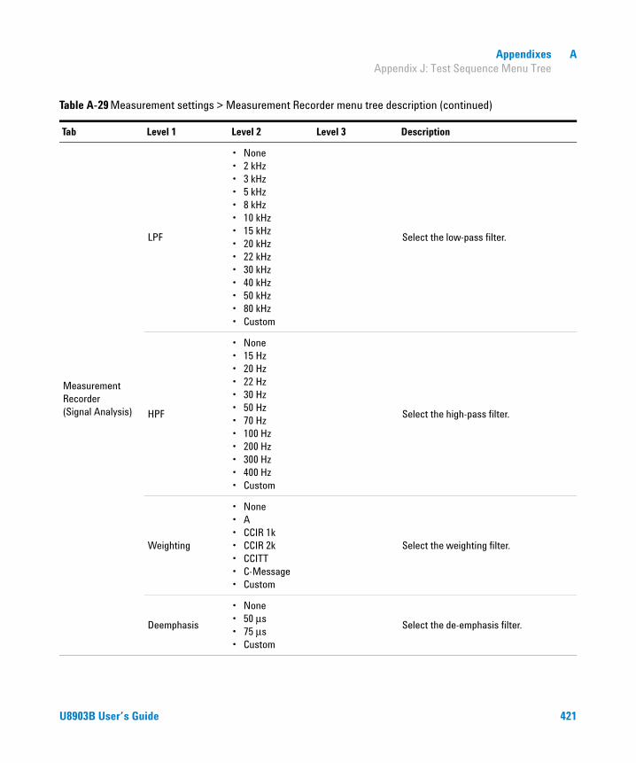
Appendixes A Appendix J: Test Sequence Menu Tree
Measurement Recorder (Signal Analysis)
LPF
• None• 2 kHz• 3 kHz• 5 kHz• 8 kHz• 10 kHz• 15 kHz• 20 kHz• 22 kHz• 30 kHz• 40 kHz• 50 kHz• 80 kHz• Custom
Select the low-pass filter.
HPF
• None• 15 Hz• 20 Hz• 22 Hz• 30 Hz• 50 Hz• 70 Hz• 100 Hz• 200 Hz• 300 Hz• 400 Hz• Custom
Select the high-pass filter.
Weighting
• None• A• CCIR 1k• CCIR 2k• CCITT• C-Message• Custom
Select the weighting filter.
Deemphasis
• None• 50 μs• 75 μs• Custom
Select the de-emphasis filter.
Table A-29 Measurement settings > Measurement Recorder menu tree description (continued)
Tab Level 1 Level 2 Level 3 Description
U8903B User’s Guide 421
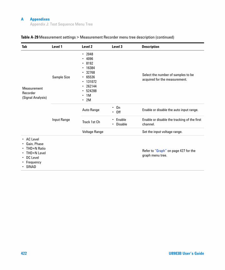
A Appendixes Appendix J: Test Sequence Menu Tree
Measurement Recorder (Signal Analysis)
Sample Size
• 2048• 4096• 8192• 16384• 32768• 65536• 131072• 262144• 524288• 1M• 2M
Select the number of samples to be acquired for the measurement.
Input Range
Auto Range• On• Off
Enable or disable the auto input range.
Track 1st Ch• Enable• Disable
Enable or disable the tracking of the first channel.
Voltage Range Set the input voltage range.
• AC Level• Gain, Phase• THD+N Ratio• THD+N Level• DC Level• Frequency• SINAD
Refer to “Graph” on page 427 for the graph menu tree.
Table A-29 Measurement settings > Measurement Recorder menu tree description (continued)
Tab Level 1 Level 2 Level 3 Description
422 U8903B User’s Guide

Appendixes A Appendix J: Test Sequence Menu Tree
POLQA
Table A-30 Measurement settings > POLQA menu tree description
Tab Level 1 Level 2 Level 3 Description
POLQA
Analysis Mode• Basic• Advanced
Select the POLQA analysis mode.
Playback File Path
Select the playback wave file source to be used.
Refer to “Appendix I: Recall Menu Tree” for the recall menu tree.
This setting is only available when Analysis Mode is set to Basic.
Degraded File Path
Select the degraded wave file source to be used.
Refer to “Appendix I: Recall Menu Tree” for the recall menu tree.
This setting is only available when Analysis Mode is set to Basic.
Reference Source
(This setting is only available when Analysis Mode is set to Advanced)
Source• File• Generator
Select file or generator as the reference source.
Playback File Path
Select the wave file source to be used.
This setting is only available when Source is set to File.
Playback ChSelect the generator channel to play the reference file or waveform.
Recording ChSelect the playback file or the recorded wave file from an analyzer channel as the reference file.
Rec Duration
Set the recording duration used to record the playback wave file from an analyzer channel.
This setting is only available when Recording Ch is set to analyzer channel.
U8903B User’s Guide 423

A Appendixes Appendix J: Test Sequence Menu Tree
POLQA
Reference Source
(This setting is only available when Analysis Mode is set to Advanced)
Delay
Set the delay in seconds before a recording is performed after the generator is turned on.
This setting is only available when Recording Ch is set to analyzer channel.
Save to File
Enable or disable automatically save the reference file.
This setting is only available when Recording Ch is set to an analyzer channel.
Save File Path
Set the location to save the reference file.
This setting is only available when Save to File is enabled.
Degraded Source
(This setting is only available when Analysis Mode is set to Advanced)
Source• File• AA1 to AA8
Select the degraded wave file or an existing file to be recorded.
Save to File
Enable or disable the recording of the degraded wave file.
This setting is only available when Source is set to an analyzer channel.
Degraded File Path
Set the location to save the degraded wave file.
This setting is only available when Source is set to File.
Rec Duration
Set the recording duration used to record the degraded wave file.
This setting is only available when Source is set to an analyzer channel.
Delay
Set the delay in seconds before a recording is performed after the generator is turned on.
This setting is only available when Source is set to an analyzer channel.
Table A-30 Measurement settings > POLQA menu tree description (continued)
Tab Level 1 Level 2 Level 3 Description
424 U8903B User’s Guide

Appendixes A Appendix J: Test Sequence Menu Tree
POLQA POLQA Config
Bandwidth• SWB• NB
Select the analysis bandwidth.
Auto Lvl Align• Yes• No
Enable or disable the automatic level alignment.
Auto Fs• Yes• No
Enable or disable the resampling of the input signals to a suitable sample rate.
Show/Hide POLQA License
Show or hide the POLQA license information.
SurfaceRefer to “Graph” on page 427 for the graph menu tree.
• MOS- LQO• Levels• Delay
Refer to “Bar chart” on page 426 for the bar chart menu tree.
Table A-30 Measurement settings > POLQA menu tree description (continued)
Tab Level 1 Level 2 Level 3 Description
U8903B User’s Guide 425

A Appendixes Appendix J: Test Sequence Menu Tree
Measurement results
Bar chart
Table A-31 Measurement Results > Bar chart menu tree description
Level 1 Level 2 Level 3 Description
Status Enable or disable the selected result tab.
Add Result Add a new result tab to the measurement.
Delete Result Delete the selected result tab from the measurement.
Save Data
Save the selected result data to a CSV file format in the internal storage or external USB flash storage.
Refer to “Appendix H: Save Menu Tree” for the save menu tree.
Edit Limits
Track 1st• Enable• Disable
Enable or disable the tracking of the first trace.
Lower limit• Enable• Disable
Enable or disable the lower limit.
Upper limit• Enable• Disable
Enable or disable the upper limit.
Lower limit Set the lower limit value.
Upper limit Set the upper limit value.
Graph Properties
Title Edit the bar chart title.
X-axis
Auto Scale
Enable or disable the X-axis autoscale.
• On• Off
Unit Select the X-axis unit type.
LeftSet the X-axis left value.
This setting is only available when the Autoscale is disabled.
RightSet the X-axis right value.
This setting is only available when the Autoscale is disabled.
426 U8903B User’s Guide

Appendixes A Appendix J: Test Sequence Menu Tree
Graph
Table A-32 Measurement results > Graph menu tree description
Level 1 Level 2 Level 3 Description
Status Enable or disable the selected result tab.
Add Result Add a new result tab to the measurement.
Delete Result Delete the selected result tab from the measurement.
Save Data
Save the selected result data to a CSV file format in the internal storage or external USB flash storage.
Refer to “Appendix H: Save Menu Tree” for the save menu tree.
Edit Limits
Trace
• CH1 to CH8
POLQA
• Reference• Degraded• Error
Select the trace channel number or the trace type (POLQA)
Limit Type• Upper• Lower
Select the limit type.
Track 1st• Enable• Disable
Enable or disable the tracking of the first trace.
Limit• Enable• Disable
Enable or disable the limit.
Points
Point No Set the point number.
X Set the X-axis value for the selected point number.
Y Set the Y-axis value for the selected point number.
Add Point Add a limit point.
Remove Point Remove the selected limit point.
Clear Points Clear all the limit points.
Load Points
Load limit points from a file.
Refer to “Appendix I: Recall Menu Tree” for the recall menu tree.
U8903B User’s Guide 427
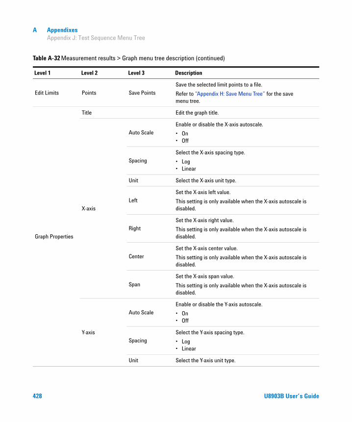
A Appendixes Appendix J: Test Sequence Menu Tree
Edit Limits Points Save Points
Save the selected limit points to a file.
Refer to “Appendix H: Save Menu Tree” for the save menu tree.
Graph Properties
Title Edit the graph title.
X-axis
Auto Scale
Enable or disable the X-axis autoscale.
• On• Off
Spacing
Select the X-axis spacing type.
• Log• Linear
Unit Select the X-axis unit type.
Left
Set the X-axis left value.
This setting is only available when the X-axis autoscale is disabled.
Right
Set the X-axis right value.
This setting is only available when the X-axis autoscale is disabled.
Center
Set the X-axis center value.
This setting is only available when the X-axis autoscale is disabled.
Span
Set the X-axis span value.
This setting is only available when the X-axis autoscale is disabled.
Y-axis
Auto Scale
Enable or disable the Y-axis autoscale.
• On• Off
Spacing
Select the Y-axis spacing type.
• Log• Linear
Unit Select the Y-axis unit type.
Table A-32 Measurement results > Graph menu tree description (continued)
Level 1 Level 2 Level 3 Description
428 U8903B User’s Guide
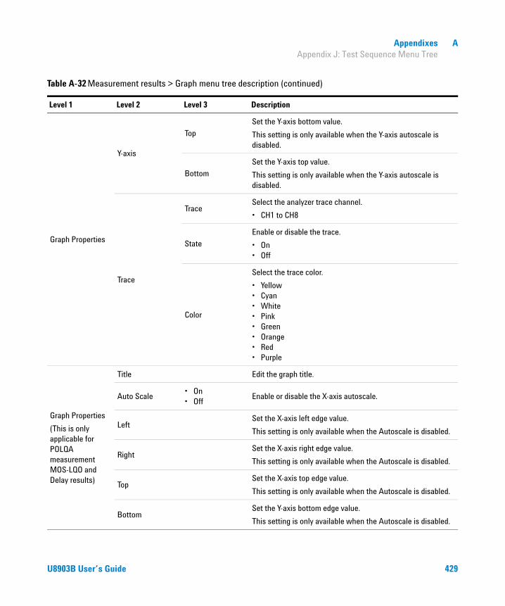
Appendixes A Appendix J: Test Sequence Menu Tree
Graph Properties
Y-axis
Top
Set the Y-axis bottom value.
This setting is only available when the Y-axis autoscale is disabled.
Bottom
Set the Y-axis top value.
This setting is only available when the Y-axis autoscale is disabled.
Trace
TraceSelect the analyzer trace channel.
• CH1 to CH8
State
Enable or disable the trace.
• On• Off
Color
Select the trace color.
• Yellow• Cyan• White• Pink• Green• Orange• Red• Purple
Graph Properties
(This is only applicable for POLQA measurement MOS-LQO and Delay results)
Title Edit the graph title.
Auto Scale• On• Off
Enable or disable the X-axis autoscale.
LeftSet the X-axis left edge value.
This setting is only available when the Autoscale is disabled.
RightSet the X-axis right edge value.
This setting is only available when the Autoscale is disabled.
TopSet the X-axis top edge value.
This setting is only available when the Autoscale is disabled.
BottomSet the Y-axis bottom edge value.
This setting is only available when the Autoscale is disabled.
Table A-32 Measurement results > Graph menu tree description (continued)
Level 1 Level 2 Level 3 Description
U8903B User’s Guide 429

A Appendixes Appendix K: HP8903B Menu Tree
Appendix K: HP8903B Menu Tree
Table A-33 HP8903B menu tree description
Level 1 Level 2 Level 3 Description
Measurement
Function
• AC LEVEL• SINAD• DISTN• DC LEVEL• SIG / NOISE• DISTN LEVEL
Select the HP8903B measurement mode.
LP Filter• None• 30 kHz• 80 kHz
Select the HP8903B measurement low-pass filter value.
HP/W Filter
Select the HP8903B high-pass or weighting filter value.
The filter selection depends on the left and right filters set at “HP8903B Config”.
Reference
Set the reference value to be compared with the measured value in ratio mode.
Changing the reference value will enable the measurement ratio mode.
Ratio• On• Off
Enable or disable the HP8903B measurement ratio mode.
Format• Log• Lin
Select the HP8903B measurement format type.
Generator
Frequency
Set the HP8903B generator frequency value.
Changing the frequency value will also set the step parameter to frequency.
Amplitude
Set the HP8903B generator amplitude value.
Changing the amplitude value will also set the step parameter to amplitude.
Step Param• Frequency• Amplitude
Select the HP8903B generator step parameter type.
430 U8903B User’s Guide

Appendixes A Appendix K: HP8903B Menu Tree
Generator
Freq. Step
Set the HP8903B generator frequency step value.
This setting is only available when the step parameter is set to frequency.
Amp. Step
Set the HP8903B generator amplitude step value.
This setting is only available when the step parameter is set to amplitude.
x 10 Multiply the current parameter step value by 10.
÷ 10 Divide the current parameter step value by 10.
Sweep
Freq. Start Set the HP8903B sweep frequency start value.
Freq. Stop Set the HP8903B sweep frequency stop value.
Sweep Status• On• Off
Start or abort sweeping in the HP8903B mode.
Code List
• None• Input Level Range (except DC Level)• Input Level Range (DC Level only)• Post Notch Detector Response
(except in SINAD)• Display Source Settings• Re-enter Ratio Mode• Signal-to-Noise Measurement Delay• SINAD and Signal-to-Noise Display
Resolution• Sweep Resolution (maximum 255
points/sweep)• Display Level in Watts• Read Display to SCPI• GPIB Address (SCPI only)• GPIB Service Request Condition
(SCPI only)• Source Output Impedance
(Instrument powers up at 600 Ω)
Select the HP8903B special function codes list to be displayed.
SPCLSet the HP8903B special function code except those indicated as SCPI only and execute the special function.
Table A-33 HP8903B menu tree description (continued)
Level 1 Level 2 Level 3 Description
U8903B User’s Guide 431

A Appendixes Appendix L: Units of the Measurement Function Returned Values
Appendix L: Units of the Measurement Function Returned Values
Analog analyzer
Table A-34 Analog analyer units of the meaurement function returned values
Measurement function Unit Default
Frequency• Hz• ΔHz
Hz
AC voltage THD+N level THD level
• dBg• dBm• dBr• dBu• dBV• W• V• ΔV• dBSPL• x
V
DC voltage• V• ΔV• x
V
THD+N ratio SINAD THD ratio SMPTE IMD DFD IEC 60118 (2nd order) DFD IEC 60118 (3rd order) DFD IEC 60268 (2nd order) DFD IEC 60268 (3rd order) SNR SNR (Fast) Crosstalk
• dB• ΔdB• %• x
dB
Phase ° °
432 U8903B User’s Guide

Appendixes A Appendix L: Units of the Measurement Function Returned Values
The units can be computed using the following formulas.
Table A-35 Unit conversion formula
Unit Formula Description
ΔHz f – fref fref = Reference frequency
dB 20 × log10 (ratio) -
ΔdB (ratio) – Rref Rref = Reference ratio
dBgVgen = Amplitude of the generator signal for a corresponding channel
dBm Zref = Reference impedance
dBr Vref = Reference level
dBu -
dBv 20 × log10(Vrms) -
W Zref = Reference impedance[1]
ΔV V – Vref Vref = Reference level[2]
x
Vref = Reference level[2]
Rref = Reference ratio
% 100 × (ratio) -
20 log10
Vrms2
Vgen-------------------⎝ ⎠⎜ ⎟⎜ ⎟⎛ ⎞
×
10 log10
1000 Vrms2
Zref---------------------------------⎝ ⎠⎜ ⎟⎜ ⎟⎛ ⎞
×
20 log10
Vrms2
Vref-------------------⎝ ⎠⎜ ⎟⎜ ⎟⎛ ⎞
×
20 log10
Vrms
0.6--------------⎝ ⎠⎜ ⎟⎛ ⎞
×
VZref----------
VVref-----------
or
Ratio (in %)Rref (in %)------------------------------
U8903B User’s Guide 433
A Appendixes Appendix L: Units of the Measurement Function Returned Values
[1] When the Vrms measurement unit is changed to Watt or dBm, the reference impedance setting will be used for the power level calculation. The reference impedance refers to the circuitry impedance or load impedance connected to the analyzer when calculating power level. Note that in a loopback test with no load impedance, the measured voltage value will be twice the expected value as there is no voltage divider present. This will return a power measurement greater than 6.02 dB if a load is present.
[2] Reference level is defined as a user-entered or a captured value from the current reading as a relative level for the subsequent measurement reading. It can be set to delta, linear, or log scale.
434 U8903B User’s Guide

Appendixes A Appendix M: Arbitrary File Format
Appendix M: Arbitrary File Format
The U8903B arbitrary waveform mode allows you to load an arbitrary file or a wave file. To load waveform file for the analog arbitrary waveform, press the Waveform Config > Recall softkeys. The Recall menu page will be displayed to allow you to select the file to be loaded. Once you load the waveform file, press the Info softkey in the Waveform Config menu page to display the arbitrary waveform information as shown in Figure A- 1.
Figure A-1 Analog Generator > Waveform Config > Info menu page (arbitrary waveform)
You may configure the arbitrary file format (*.arb) with the parameters as shown below.
#Vpeak: 2 #DC Offset: 0 #Points: 0 -0.2 -0.4 . . .
The allowable range of values for each arbitrary file parameters are as shown in Table A- 36.
U8903B User’s Guide 435

A Appendixes Appendix M: Arbitrary File Format
The sampling rate for the arbitrary waveform is fixed at 312.5 kHz. Thus, the interval between samples is 3.2 μs (1/312.5).
For the following arbitrary file example, the highest numerical number of the sample points, which is 6, is output with the Vpeak. The other samples are level- controlled according to their ratio to the maximum.
#Vpeak: 2 #DC offset: –3 #Points: 0 –1 –1.5 –1 0 2 4 6 4 2 . . .
Table A-36 Allowable range for arbitrary file parameters
Parameter Range
Vpeak • 0 to 22.6 Vp (Balanced output connection)• 0 to 11.3 Vp (Unbalanced or common output connection)
DC Offset –11.3 V to 11.3 V
Points 32 to 32768 points
NOTE When the DC offset and amplitude are added together, it must not exceed the maximum voltage for the current output connection type:
• For the balanced output connection, (Vpeak + |DC offset|) must be within 0 V and 22.6 V.
• For the unbalanced and common mode output connections, (Vpeak + |DC offset|) must be within 0 V and 11.3 V.
436 U8903B User’s Guide

Appendixes A Appendix M: Arbitrary File Format
Any of the following conditions may cause an error or warning message to appear.
• Unable to load the sample points, as the points may not be a valid float.
• Summation of the Vpeak and DC offset exceeds the maximum voltage for the current output connection type.
• Invalid Vpeak and DC offset values.
• Total of sample points less than 32.
• The arbitrary file does not exist.
U8903B User’s Guide 437
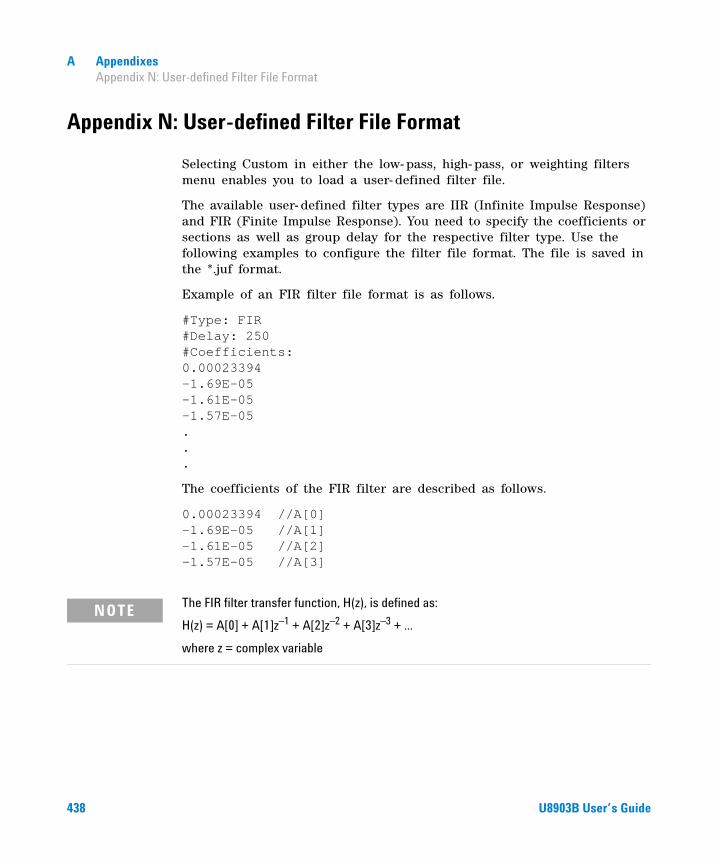
A Appendixes Appendix N: User-defined Filter File Format
Appendix N: User-defined Filter File Format
Selecting Custom in either the low- pass, high- pass, or weighting filters menu enables you to load a user- defined filter file.
The available user- defined filter types are IIR (Infinite Impulse Response) and FIR (Finite Impulse Response). You need to specify the coefficients or sections as well as group delay for the respective filter type. Use the following examples to configure the filter file format. The file is saved in the *.juf format.
Example of an FIR filter file format is as follows.
#Type: FIR #Delay: 250 #Coefficients: 0.00023394 -1.69E-05 -1.61E-05 -1.57E-05 . . .
The coefficients of the FIR filter are described as follows.
0.00023394 //A[0] -1.69E-05 //A[1] -1.61E-05 //A[2] -1.57E-05 //A[3]
NOTE The FIR filter transfer function, H(z), is defined as:
H(z) = A[0] + A[1]z–1 + A[2]z–2 + A[3]z–3 + ...
where z = complex variable
438 U8903B User’s Guide
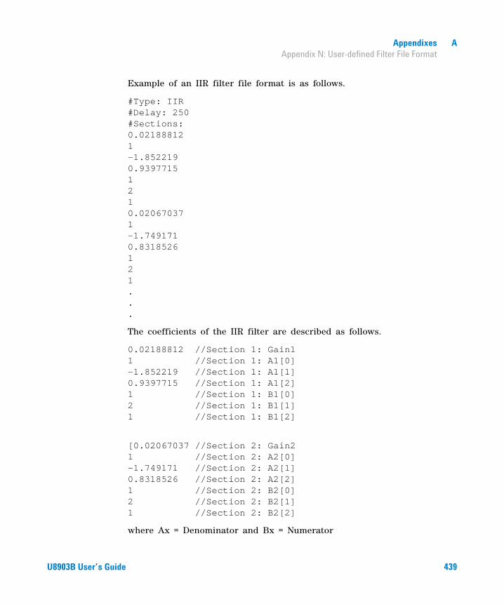
Appendixes A Appendix N: User-defined Filter File Format
Example of an IIR filter file format is as follows.
#Type: IIR #Delay: 250 #Sections: 0.02188812 1 -1.852219 0.9397715 1 2 1 0.02067037 1 -1.749171 0.8318526 1 2 1 . . .
The coefficients of the IIR filter are described as follows.
0.02188812 //Section 1: Gain1 1 //Section 1: A1[0] –1.852219 //Section 1: A1[1] 0.9397715 //Section 1: A1[2] 1 //Section 1: B1[0] 2 //Section 1: B1[1] 1 //Section 1: B1[2]
[0.02067037 //Section 2: Gain2 1 //Section 2: A2[0] –1.749171 //Section 2: A2[1] 0.8318526 //Section 2: A2[2] 1 //Section 2: B2[0] 2 //Section 2: B2[1] 1 //Section 2: B2[2]
where Ax = Denominator and Bx = Numerator
U8903B User’s Guide 439

A Appendixes Appendix N: User-defined Filter File Format
You may set up to 256 coefficients for the FIR filter type, and up to 36 sections for the IIR filter. The number of FIR coefficients must not be less than four, while the minimum number of sections allowed for IIR is one (seven coefficients). The delay is specified in the form of samples and within the range of 0 to 65535.
NOTE The IIR filter transfer function, H(z), is defined as:
where z = complex variable, N = number of sections, x = section number
H(z) Gainx
Bx 0[ ] Bx 1[ ]z–1
Bx 2[ ]z–1
+ +
Ax 0[ ] Ax 1[ ]z–1
Ax 2[ ]z–1
+ +-----------------------------------------------------------------------------------⎝ ⎠⎜ ⎟⎜ ⎟⎛ ⎞
x = 1
N
∏=
440 U8903B User’s Guide

Appendixes A Appendix O: U8903B Default Settings
Appendix O: U8903B Default Settings
Analog generator
Table A-37 Analog generator default settings
Level 1 Level 2 Level 3 Default
Waveform Sine
Waveform Config
Amplitude 0 Vrms
Frequency 1 kHz
DC Offset 0 V
Phase -> 1 0°
Frequency 2 2 kHz
Ratio 100%
Lower Feq 60 Hz
Upper Freq (SMPTE 1:1/4:1/10:1)
7 kHz
Upper Freq (IEC 60118) 10 kHz
Diff Freq 80 Hz
Center Freq 10 kHz
Voltage 0 V
Start Freq 1001.35803222656
Stop Freq 4997.25341796875
Freq Spacing Linear
Tones 2
Length 1024
Dial (DTMF) Mode Single
Amplitude (DTMF) –4.5 dBu
U8903B User’s Guide 441
A Appendixes Appendix O: U8903B Default Settings
Analog analyzer
Waveform Config
Ratio (DTMF) 2 dB
Tone Duration (DTMF) 90 ms
Tone Delay (DTMF) 90 ms
Pause Time (DTMF) 90 ms
Repeat (DTMF) Off
Output Config
Connector UnBal
Impedance 600 Ω
IEC60268 10 Ω Pin 2
Ground Float
Max Voltage 22.6 Vrms
References Ref Impedance 600 Ω
Table A-37 Analog generator default settings (continued)
Level 1 Level 2 Level 3 Default
Table A-38 Analog analyzer default settings
Level 1 Level 2 Level 3 Default
Functions
Multi-Chn Mode Off
Function No. 1
Meas. Func. (Function 1) AC Voltage
Meas. Func. (Function 2) Frequency
Meas. Func. (Function 3) None
Meas. Func. (Function 4) None
Functions (Frequency)
Unit Hz
Format Off
442 U8903B User’s Guide
Appendixes A Appendix O: U8903B Default Settings
Functions (AC Voltage)
Unit V
Format Off
Detector RMS
Functions (DC Voltage)
Unit V
Format Off
Functions (THD+N Ratio/SINAD)
Unit dB
Format Off
Freq Lock Auto
Fund Freq 1000
Functions (THD+N Level)
Unit V
Format Off
Freq Lock Auto
Fund Freq 1000
Functions (THD Ratio)
Unit dB
Format Off
Even Harmonic 2, 4, 6, 8
Odd Harmonic 3, 5, 7, 9
Freq Lock Auto
Fund Freq 1000
Functions (THD Level)
Unit V
Format Off
Even Harmonic 2, 4, 6, 8
Odd Harmonic 3, 5, 7, 9
Freq Lock Auto
Fund Freq 1000
Table A-38 Analog analyzer default settings (continued)
Level 1 Level 2 Level 3 Default
U8903B User’s Guide 443

A Appendixes Appendix O: U8903B Default Settings
Functions (DFD60268 2nd/ DFD 60268 3rd/ DFD 60118 2nd/ DFD 60118 3rd)
Unit dB
Format Off
Functions (SMPTE IMD)
Unit dB
Format Off
Freq Lock Gen Lock
Upper Freq 60
Lower Freq 7000
Functions (SNR)
Unit dB
Format Off
SNR Delay 0 ms
Functions (SNR (Fast))
Unit dB
Format Off
Freq Lock Auto
Fund Freq 1000
Harmonics 5
Functions (Phase)
Ref. Channel 1
Freq Lock Auto
Fund Freq 1000
Functions (X-Talk)
Ref. Channel 1
Unit dB
Format Off
Freq Lock Auto
Fund Freq 1000
Table A-38 Analog analyzer default settings (continued)
Level 1 Level 2 Level 3 Default
444 U8903B User’s Guide

Appendixes A Appendix O: U8903B Default Settings
Filters Config
LPF None
HPF None
Weighting None
Deemphasis None
Notch Filter
State Disabled
Center Freq 1000 Hz
Bandwidth 500 Hz
Meas Config
Auto Range On
Range 1 V
Sample Size 32768
Average Points 1
Src Channel 1
Meas ConfigTrigger Source Free Run
Trigger Edge Rising
Input Config
Connector UnBal
Impedance100 kΩ (Unbal)
200 kΩ (Bal)
Coupling AC
Bandwidth 90 kHz
Ext. Gain 0 dB
Wave File
Channel Left
Bits/Sample 8
Duration 10 s
Table A-38 Analog analyzer default settings (continued)
Level 1 Level 2 Level 3 Default
U8903B User’s Guide 445

A Appendixes Appendix O: U8903B Default Settings
Sweep
Statistics
Show Stats Off
No. of Reading 10
Stat 1 Min
Stat 2 Max
Stat 3 Average
Table A-38 Analog analyzer default settings (continued)
Level 1 Level 2 Level 3 Default
Table A-39 Sweep default settings
Level 1 Level 2 Default
Legacy Status Off
Parameter Frequency
Points Settings
Spacing Log
Unit Hz
Start 20
Stop 2000
Step 1.268961003
Points 30
Points Settings (Parameter = Amplitude)
Spacing Linear
Unit Vrms
Start 0.1
Stop 1
Step 0.031034483
Points 30
446 U8903B User’s Guide
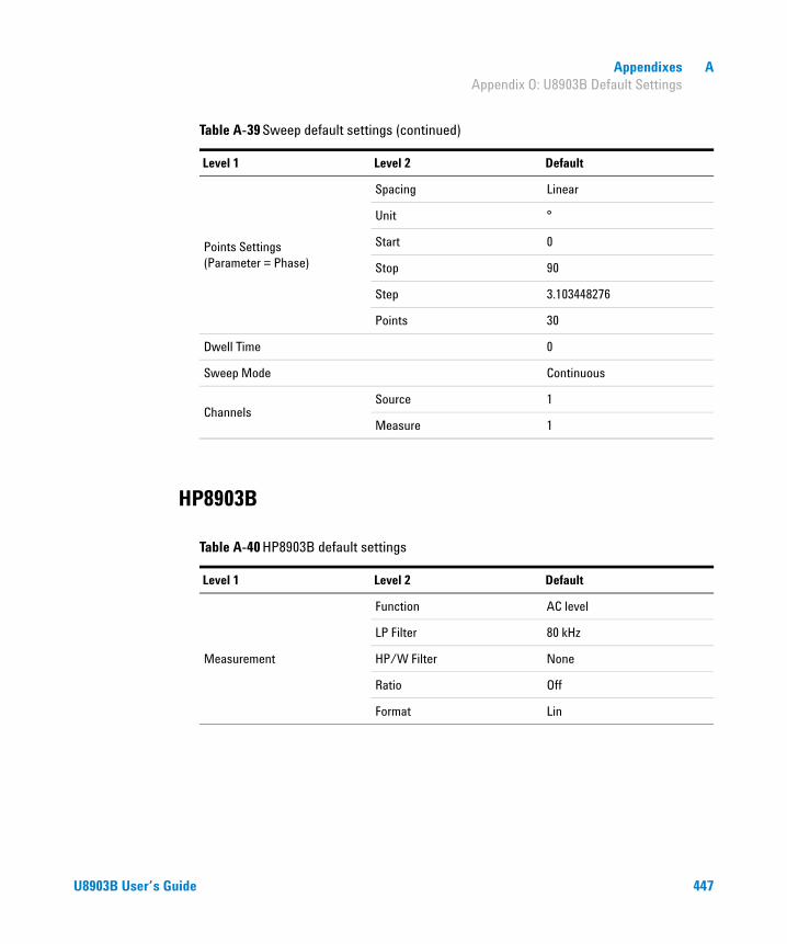
Appendixes A Appendix O: U8903B Default Settings
HP8903B
Points Settings (Parameter = Phase)
Spacing Linear
Unit °
Start 0
Stop 90
Step 3.103448276
Points 30
Dwell Time 0
Sweep Mode Continuous
ChannelsSource 1
Measure 1
Table A-39 Sweep default settings (continued)
Level 1 Level 2 Default
Table A-40 HP8903B default settings
Level 1 Level 2 Default
Measurement
Function AC level
LP Filter 80 kHz
HP/W Filter None
Ratio Off
Format Lin
U8903B User’s Guide 447

A Appendixes Appendix O: U8903B Default Settings
System
Generator
Frequency 1 kHz
Amplitude 0 V
Step Param Frequency
Freq. Step 1 kHz
Amp. Step 100 mVrms
SweepFreq. Start 20 Hz
Freq. Stop 20 kHz
Table A-40 HP8903B default settings (continued)
Level 1 Level 2 Default
Table A-41 System default settings
Key Level 1 Level 2 Default
System HP8903B Config
Active Channel 1
Left Filter None
Right Filter None
Default LPF 80 kHz
448 U8903B User’s Guide

© Agilent Technologies, Inc. 2014
First Edition, June 4, 2014U8903-90045
www.agilent.com
Agilent Technologies
Contact usTo obtain service, warranty, or technical assistance, contact us at the following phone or fax numbers:
United States:
(tel) 800 829 4444 (fax) 800 829 4433
Canada:
(tel) 877 894 4414 (fax) 800 746 4866
China:
(tel) 800 810 0189 (fax) 800 820 2816
Europe:
(tel) 31 20 547 2111
Japan:
(tel) 0120 (421) 345 (fax) 0120 (421) 678
Korea:
(tel) (080) 769 0800 (fax) (080) 769 0900
Latin America:
(tel) (305) 269 7500
Taiwan:
(tel) 0800 047 866 (fax) 0800 286 331
Other Asia Pacific Countries:
(tel) (65) 6375 8100 (fax) (65) 6755 0042
Or visit Agilent World Wide Web at:www.agilent.com/find/assist
Product specifications and descriptions in this document are subject to change without notice. Always refer to the English version at the Agilent Web site for the latest revision.