Embed Size (px)
Citation preview
The first choice for field testing ofDVB-C signals on your cable TVsystem All cable TV network operators planning the introduction of DVB-C(Digital Video Broadcast via Cable)services have increasing competitivepressure to install these new servic-es—quickly. Aggressive activationschedules require test equipmentcapable of verifying your quality ofservice—fast. The Agilent Technologies8594Q QAM1 analyzer is a comprehen-sive and powerful test solution forinstallation and maintenance test onEuropean DVB-C systems. Supporting8, 4, and 2 MHz channel bandwidths,2
the 8594Q QAM analyzer makes bothqualitative and quantitative measure-ments on the transmitted QAM signal.It gives engineers the measurementcapability required to accurately veri-fy the quality of service delivered tosubscribers. All measurements arepresented in a user friendly mannerso the engineer can focus on the jobat hand, not on operating the testequipment.
The 8594Q QAM analyzer can helpyou during:
• Headend equipment installationand maintenance
• System verification • Field installation and maintenance • Modulator manufacturing test
The 8594Q QAM analyzer demodu-lates and accurately measures theQAM signals carried through theDVB-C system. It provides new meas-urement metrics necessary to charac-terize these signals and troubleshootproblems. The 8594Q QAM analyzer’sclear user interface and one-buttonmeasurement capability will make thetransition from analog to digital test-ing easy for cable TV engineers.
1. QAM–Quadrature Amplitude Modulation. The 8594QQAM analyzer supports 16, 64, and 256 state QAM.
2. Option J91 provides RF and modulation analysis onQAM systems using 6 MHz channel bandwidths andusing alternate coding standards.
Agilent 8594Q QAM Analyzer
DVB-C SolutionsProduct Overview
2
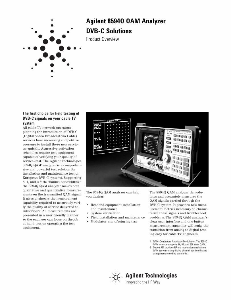
Activate your DVB-C servicesfaster To help you activate your DVB-C serv-ices faster, test equipment must pro-vide a comprehensive suite of meas-urements. The ability to analyze thesignals on the system in detail willhelp you to quickly identify and trou-bleshoot problems. With the newchallenge of testing digital signals itis important that your test equipmentis easy to use. With the 8594Q QAManalyzer’s one button measurementcapability, engineers will be able toconcentrate on getting measurementresults, not finding the right menu.The portable, rugged 8594Q QAManalyzer is ideal for testing from theheadend through the network to thesubscriber drop.
This combination of powerful meas-urements and usability will ease yourtransition from analog to DVB-C testing.
Digital video measurementoverview The shift from analog to digital tech-nology brings many new measure-ment challenges. Analog system meas-urements which would have indicateda high quality of service are no longerappropriate. Where analog signalsdegrade slowly as impairmentsbecome worse, digital signals will pro-vide excellent picture quality thendegrade very rapidly upon reachingthe threshold. Analyzing these digitalsignals in detail is crucial to deter-mining the real quality of servicebeing delivered to your customer.
Verify your quality of service
3
Comprehensive measurementcapability To accurately verify your quality ofservice the following measurementsare important:
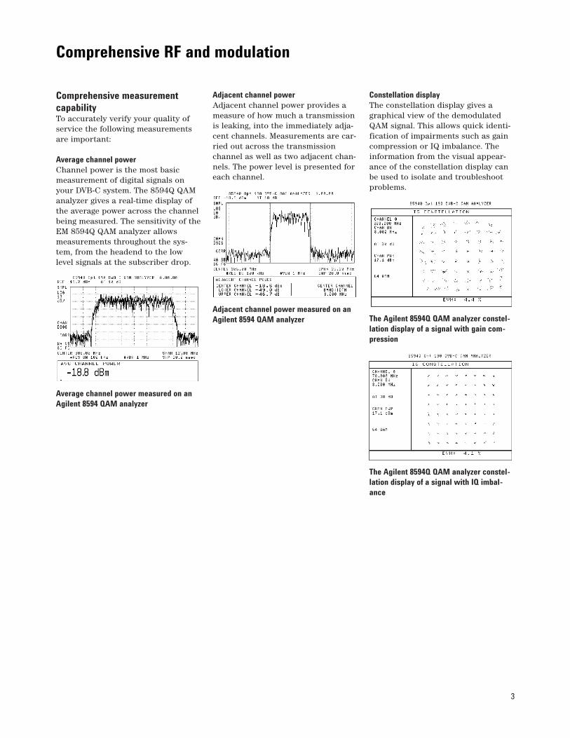
Average channel power Channel power is the most basicmeasurement of digital signals onyour DVB-C system. The 8594Q QAManalyzer gives a real-time display ofthe average power across the channelbeing measured. The sensitivity of theEM 8594Q QAM analyzer allowsmeasurements throughout the sys-tem, from the headend to the lowlevel signals at the subscriber drop.
Average channel power measured on anAgilent 8594 QAM analyzer
Adjacent channel power Adjacent channel power provides ameasure of how much a transmissionis leaking, into the immediately adja-cent channels. Measurements are car-ried out across the transmissionchannel as well as two adjacent chan-nels. The power level is presented foreach channel.
Adjacent channel power measured on anAgilent 8594 QAM analyzer
Constellation display The constellation display gives agraphical view of the demodulatedQAM signal. This allows quick identi-fication of impairments such as gaincompression or IQ imbalance. Theinformation from the visual appear-ance of the constellation display canbe used to isolate and troubleshootproblems.
The Agilent 8594Q QAM analyzer constel-lation display of a signal with gain com-pression
The Agilent 8594Q QAM analyzer constel-lation display of a signal with IQ imbal-ance
Comprehensive RF and modulation
4
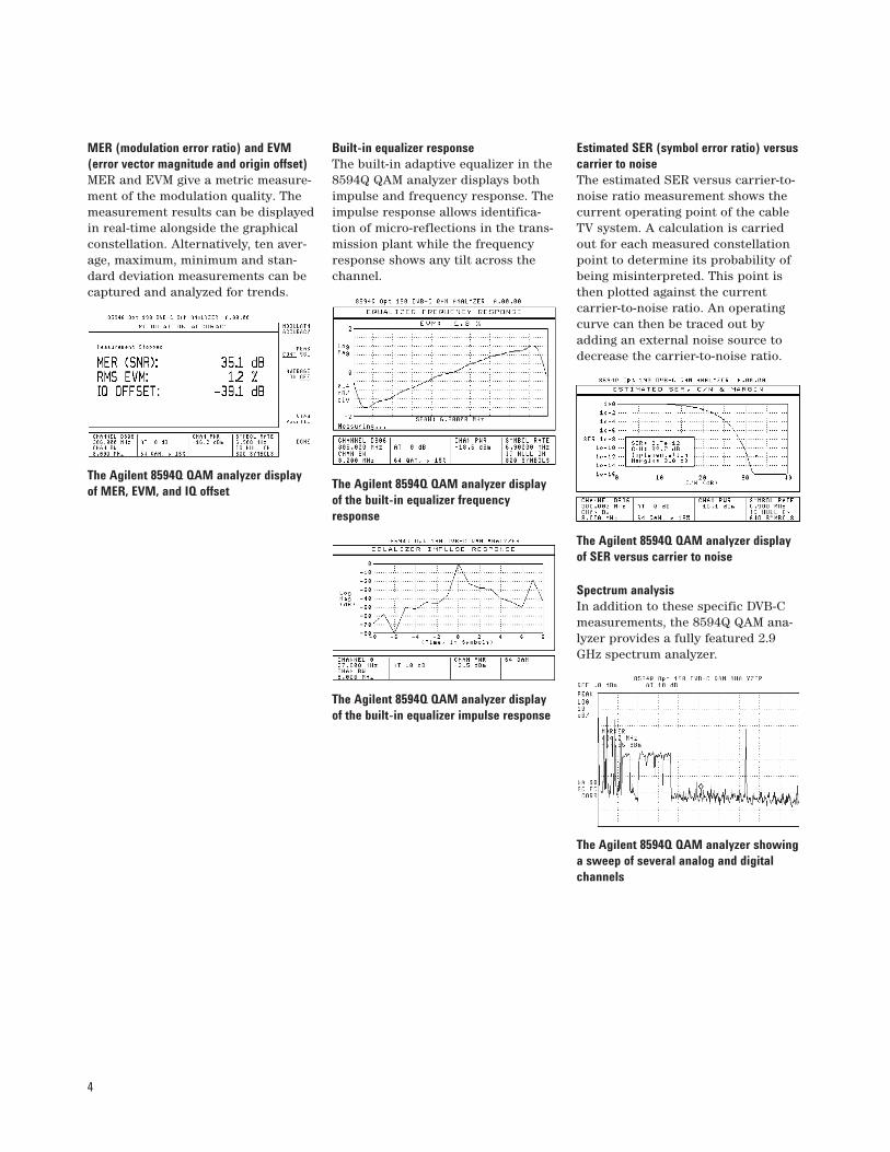
MER (modulation error ratio) and EVM(error vector magnitude and origin offset) MER and EVM give a metric measure-ment of the modulation quality. Themeasurement results can be displayedin real-time alongside the graphicalconstellation. Alternatively, ten aver-age, maximum, minimum and stan-dard deviation measurements can becaptured and analyzed for trends.
The Agilent 8594Q QAM analyzer displayof MER, EVM, and IQ offset
Built-in equalizer response The built-in adaptive equalizer in the8594Q QAM analyzer displays bothimpulse and frequency response. Theimpulse response allows identifica-tion of micro-reflections in the trans-mission plant while the frequencyresponse shows any tilt across thechannel.
The Agilent 8594Q QAM analyzer displayof the built-in equalizer frequencyresponse
The Agilent 8594Q QAM analyzer displayof the built-in equalizer impulse response
Estimated SER (symbol error ratio) versuscarrier to noise The estimated SER versus carrier-to-noise ratio measurement shows thecurrent operating point of the cableTV system. A calculation is carriedout for each measured constellationpoint to determine its probability ofbeing misinterpreted. This point isthen plotted against the current carrier-to-noise ratio. An operatingcurve can then be traced out byadding an external noise source todecrease the carrier-to-noise ratio.
The Agilent 8594Q QAM analyzer displayof SER versus carrier to noise
Spectrum analysis In addition to these specific DVB-Cmeasurements, the 8594Q QAM ana-lyzer provides a fully featured 2.9GHz spectrum analyzer.
The Agilent 8594Q QAM analyzer showinga sweep of several analog and digitalchannels
5
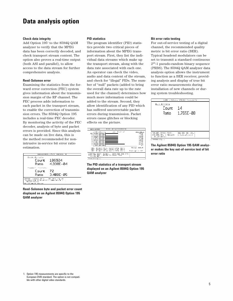
Check data integrity Add Option 1951 to the 8594Q QAManalyzer to verify that the MPEG data has been correctly decoded, andcheck transport stream content. Theoption also proves a real-time output(both ASI and parallel), to allowaccess to the data stream for furthercomprehensive analysis.
Reed-Solomon error Examining the statistics from the for-ward error correction (FEC) systemgives information about the transmis-sion margin of the RF channel. TheFEC process adds information toeach packet in the transport stream,to enable the correction of transmis-sion errors. The 8594Q Option 195includes a real-time FEC decoder. By monitoring the activity of the FECdecoder, analysis of byte and packeterrors is provided. Since this analysiscan be made on live data, this isthe method recommended for non-intrusive in-service bit error ratioestimation.
Reed-Solomon byte and packet error countdisplayed on an Agilent 8594Q Option 195QAM analyzer
PID statistics The program identifier (PID) statis-tics provide two critical pieces ofinformation about the MPEG trans-port stream. First, they list the indi-vidual data streams which make upthe transport stream, along with thedata rate associated with each one.An operator can check the video,audio and data content of the stream,and check for “illegal” PIDs. The num-ber of “null” packets (added to bringthe overall data rate up to the rateused for the channel) determines howmuch more information could beadded to the stream. Second, theyallow identification of any PID whichhas suffered uncorrectable packeterrors during transmission. Packeterrors cause glitches or blockingeffects on the picture.
The PID statistics of a transport streamdisplayed on an Agilent 8594Q Option 195QAM analyzer
Bit error ratio testing For out-of-service testing of a digitalchannel, the recommended qualitymetric is bit error ratio (BER).Typical headend modulators can beset to transmit a standard continuous223-1 pseudo-random binary sequence(PRBS). The 8594Q QAM analyzer dataanalysis option allows the instrumentto function as a BER receiver, provid-ing analysis and display of true biterror ratio measurements duringinstallation of new channels or dur-ing system troubleshooting.
The Agilent 8594Q Option 195 QAM analyz-er makes the key out-of-service test of biterror ratio
1. Option 195 measurements are specific to theEuropean DVB standard. The option is not compati-ble with other digital video standards.
Data analysis option
6
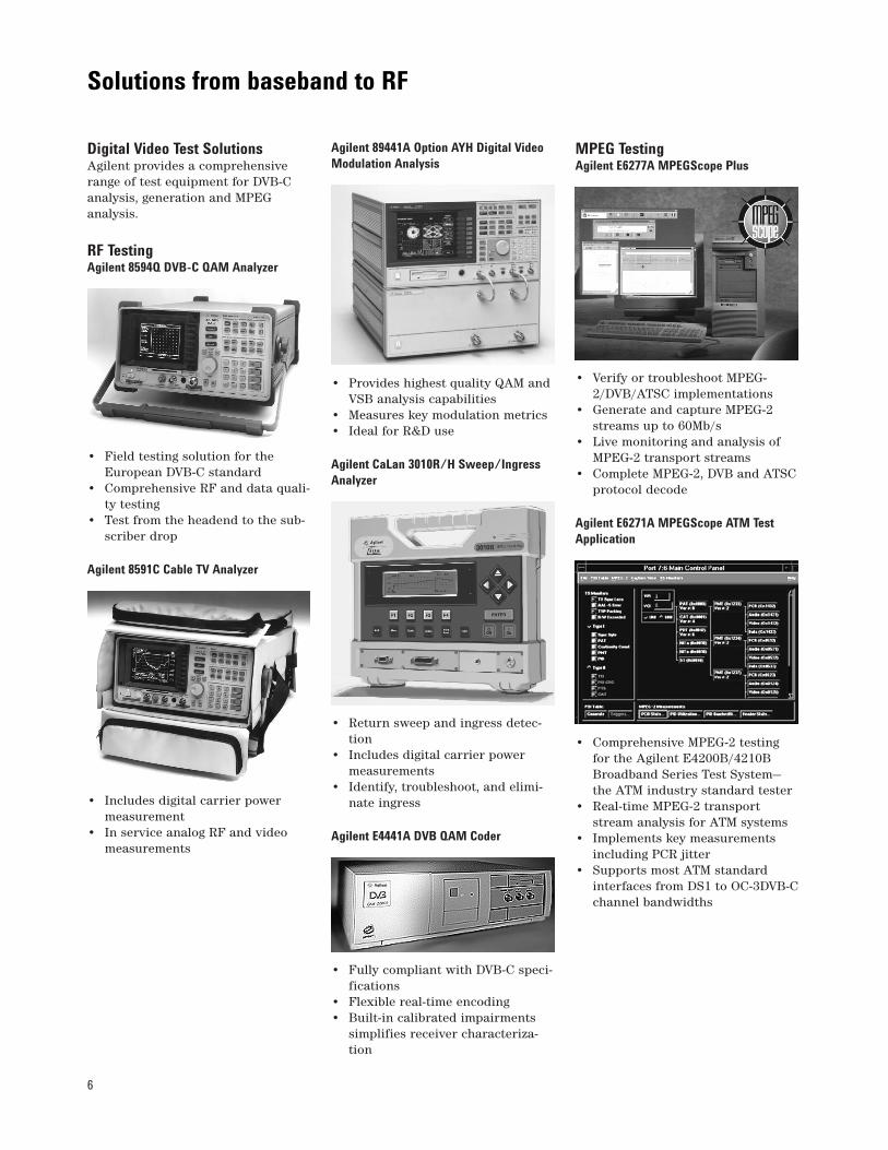
Digital Video Test Solutions Agilent provides a comprehensiverange of test equipment for DVB-Canalysis, generation and MPEG analysis.
RF Testing Agilent 8594Q DVB-C QAM Analyzer
• Field testing solution for theEuropean DVB-C standard
• Comprehensive RF and data quali-ty testing
• Test from the headend to the sub-scriber drop
Agilent 8591C Cable TV Analyzer
• Includes digital carrier powermeasurement
• In service analog RF and videomeasurements
Agilent 89441A Option AYH Digital VideoModulation Analysis
• Provides highest quality QAM andVSB analysis capabilities
• Measures key modulation metrics • Ideal for R&D use
Agilent CaLan 3010R/H Sweep/IngressAnalyzer
• Return sweep and ingress detec-tion
• Includes digital carrier powermeasurements
• Identify, troubleshoot, and elimi-nate ingress
Agilent E4441A DVB QAM Coder
• Fully compliant with DVB-C speci-fications
• Flexible real-time encoding • Built-in calibrated impairments
simplifies receiver characteriza-tion
MPEG Testing Agilent E6277A MPEGScope Plus
• Verify or troubleshoot MPEG-2/DVB/ATSC implementations
• Generate and capture MPEG-2streams up to 60Mb/s
• Live monitoring and analysis ofMPEG-2 transport streams
• Complete MPEG-2, DVB and ATSCprotocol decode
Agilent E6271A MPEGScope ATM TestApplication
• Comprehensive MPEG-2 testing for the Agilent E4200B/4210BBroadband Series Test System—the ATM industry standard tester
• Real-time MPEG-2 transportstream analysis for ATM systems
• Implements key measurementsincluding PCR jitter
• Supports most ATM standardinterfaces from DS1 to OC-3DVB-Cchannel bandwidths
Solutions from baseband to RF
7
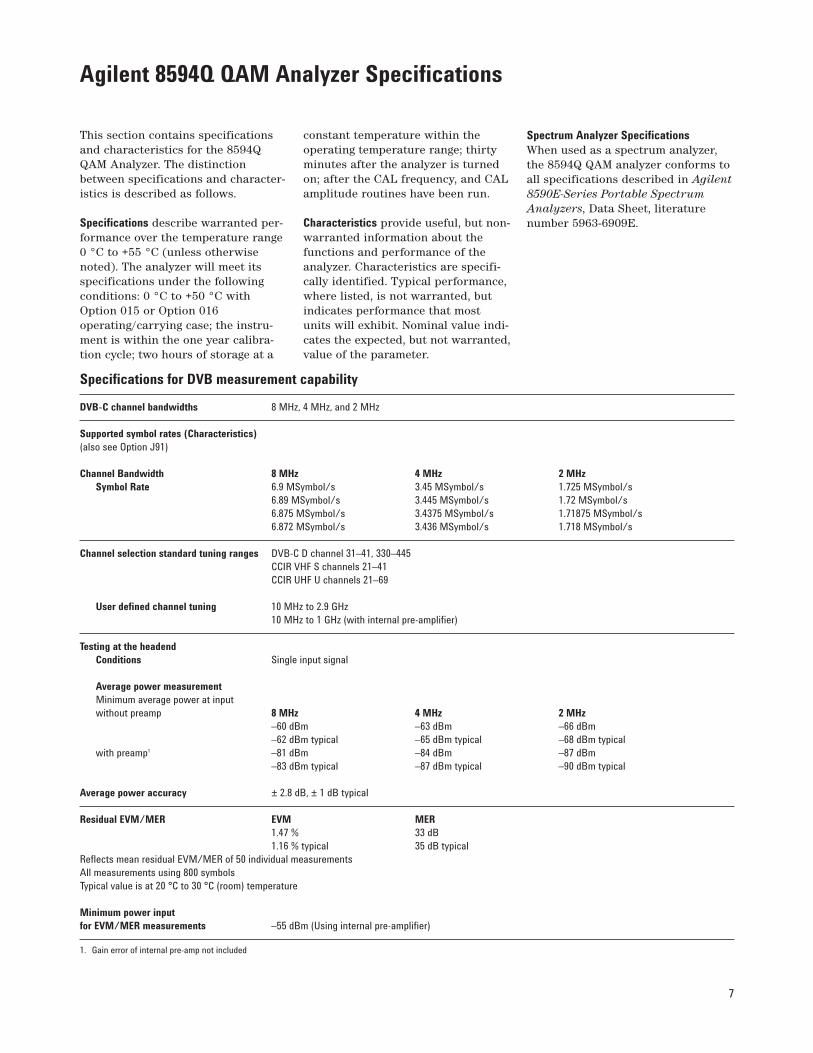
This section contains specificationsand characteristics for the 8594QQAM Analyzer. The distinctionbetween specifications and character-istics is described as follows.
Specifications describe warranted per-formance over the temperature range0 °C to +55 °C (unless otherwisenoted). The analyzer will meet itsspecifications under the followingconditions: 0 °C to +50 °C withOption 015 or Option 016operating/carrying case; the instru-ment is within the one year calibra-tion cycle; two hours of storage at a
constant temperature within theoperating temperature range; thirtyminutes after the analyzer is turnedon; after the CAL frequency, and CALamplitude routines have been run.
Characteristics provide useful, but non-warranted information about thefunctions and performance of theanalyzer. Characteristics are specifi-cally identified. Typical performance,where listed, is not warranted, butindicates performance that mostunits will exhibit. Nominal value indi-cates the expected, but not warranted,value of the parameter.
Spectrum Analyzer Specifications When used as a spectrum analyzer,the 8594Q QAM analyzer conforms toall specifications described in Agilent8590E-Series Portable SpectrumAnalyzers, Data Sheet, literaturenumber 5963-6909E.
Agilent 8594Q QAM Analyzer Specifications
Specifications for DVB measurement capability
DVB-C channel bandwidths 8 MHz, 4 MHz, and 2 MHz
Supported symbol rates (Characteristics)(also see Option J91)
Channel Bandwidth 8 MHz 4 MHz 2 MHz Symbol Rate 6.9 MSymbol/s 3.45 MSymbol/s 1.725 MSymbol/s
6.89 MSymbol/s 3.445 MSymbol/s 1.72 MSymbol/s 6.875 MSymbol/s 3.4375 MSymbol/s 1.71875 MSymbol/s 6.872 MSymbol/s 3.436 MSymbol/s 1.718 MSymbol/s
Channel selection standard tuning ranges DVB-C D channel 31–41, 330–445 CCIR VHF S channels 21–41 CCIR UHF U channels 21–69
User defined channel tuning 10 MHz to 2.9 GHz 10 MHz to 1 GHz (with internal pre-amplifier)
Testing at the headendConditions Single input signal
Average power measurement Minimum average power at input without preamp 8 MHz 4 MHz 2 MHz
–60 dBm –63 dBm –66 dBm –62 dBm typical –65 dBm typical –68 dBm typical
with preamp1 –81 dBm –84 dBm –87 dBm –83 dBm typical –87 dBm typical –90 dBm typical
Average power accuracy ± 2.8 dB, ± 1 dB typical
Residual EVM/MER EVM MER 1.47 % 33 dB 1.16 % typical 35 dB typical
Reflects mean residual EVM/MER of 50 individual measurements All measurements using 800 symbols Typical value is at 20 °C to 30 °C (room) temperature
Minimum power inputfor EVM/MER measurements –55 dBm (Using internal pre-amplifier)
1. Gain error of internal pre-amp not included
8
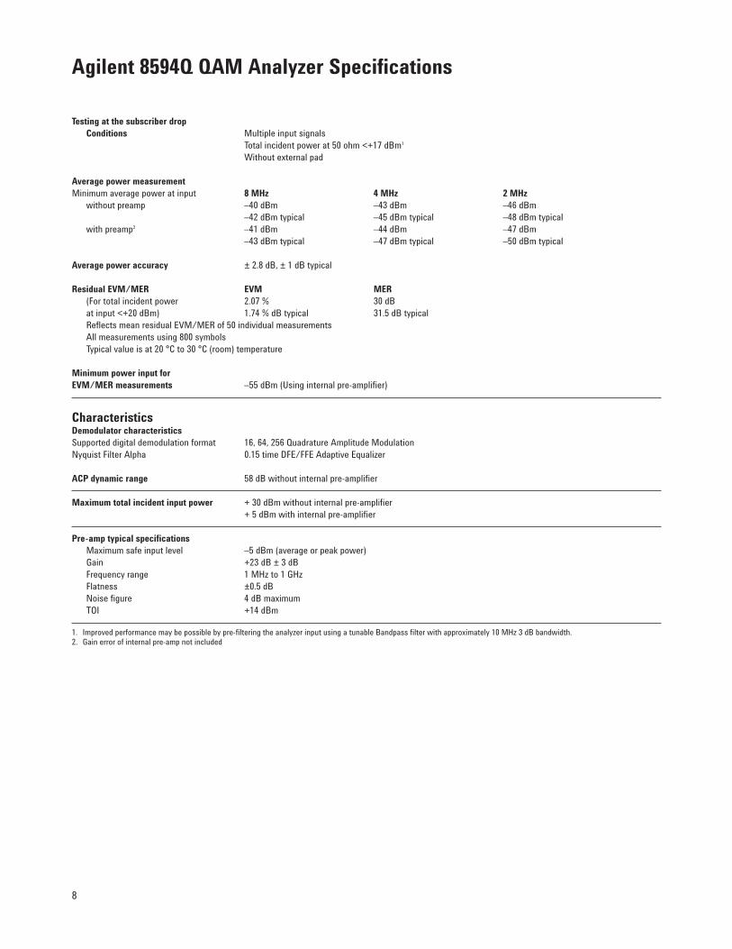
Testing at the subscriber dropConditions Multiple input signals
Total incident power at 50 ohm <+17 dBm1
Without external pad
Average power measurementMinimum average power at input 8 MHz 4 MHz 2 MHz
without preamp –40 dBm –43 dBm –46 dBm –42 dBm typical –45 dBm typical –48 dBm typical
with preamp2 –41 dBm –44 dBm –47 dBm –43 dBm typical –47 dBm typical –50 dBm typical
Average power accuracy ± 2.8 dB, ± 1 dB typical
Residual EVM/MER EVM MER(For total incident power 2.07 % 30 dB at input <+20 dBm) 1.74 % dB typical 31.5 dB typical Reflects mean residual EVM/MER of 50 individual measurements All measurements using 800 symbols Typical value is at 20 °C to 30 °C (room) temperature
Minimum power input forEVM/MER measurements –55 dBm (Using internal pre-amplifier)
Characteristics Demodulator characteristics Supported digital demodulation format 16, 64, 256 Quadrature Amplitude Modulation Nyquist Filter Alpha 0.15 time DFE/FFE Adaptive Equalizer
ACP dynamic range 58 dB without internal pre-amplifier
Maximum total incident input power + 30 dBm without internal pre-amplifier + 5 dBm with internal pre-amplifier
Pre-amp typical specificationsMaximum safe input level –5 dBm (average or peak power) Gain +23 dB ± 3 dB Frequency range 1 MHz to 1 GHz Flatness ±0.5 dB Noise figure 4 dB maximum TOI +14 dBm
1. Improved performance may be possible by pre-filtering the analyzer input using a tunable Bandpass filter with approximately 10 MHz 3 dB bandwidth.2. Gain error of internal pre-amp not included
Agilent 8594Q QAM Analyzer Specifications
9
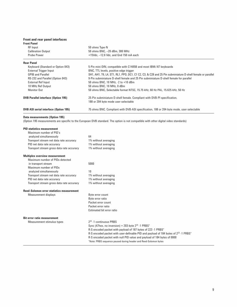
Front and rear panel interfaces Front Panel
RF Input 50 ohms Type-N Calibration Output 50 ohms BNC, –20 dBm, 300 MHz Probe Power +15Vdc, –12.6 Vdc, and Gnd 150 mA each
Rear Panel Keyboard (Standard or Option 043) 5-Pin mini-DIN, compatible with C1405B and most IBM/AT keyboards External Trigger Input BNC, TTL levels, positive edge trigger GPIB and Parallel SH1, AH1, T6, L4, ST1, RL1, PPO, DC1, C1 C2, C3, & C28 and 25 Pin subminiature D-shell female or parallel RS-232 and Parallel (Option 043) 9-Pin subminiature D-shell female and 25 Pin subminiature D-shell female for parallel External Ref Input 50 ohms BNC, 10 MHz, -2 to +10 dBm 10 MHz Ref Output 50 ohms BNC, 10 MHz, 0 dBm Monitor Out 50 ohms BNC, Selectable format NTSC, 15.75 kHz, 60 Hz PAL, 15.625 kHz, 50 Hz
DVB Parallel interface (Option 195) 25-Pin subminiature D-shell female. Compliant with DVB-PI specification, 188 or 204 byte mode user-selectable
DVB ASI serial interface (Option 195) 75 ohms BNC. Compliant with DVB-ASI specification, 188 or 204-byte mode, user-selectable
Data measurements (Option 195) (Option 195 measurements are specific to the European DVB standard. The option is not compatible with other digital video standards)
PID statistics measurement Maximum number of PID’s analyzed simultaneously 64
Transport stream net data rate accuracy 1% without averaging PID net data rate accuracy 1% without averaging Transport stream gross data rate accuracy 1% without averaging
Multiplex overview measurement Maximum number of PIDs detected in transport stream 5000
Maximum number of PIDs analyzed simultaneously 10
Transport stream net data rate accuracy 1% without averaging PID net data rate accuracy 1% without averaging Transport stream gross data rate accuracy 1% without averaging
Reed-Solomon error statistics measurement Measurement displays Byte error count
Byte error ratio Packet error count Packet error ratio Estimated bit error ratio
Bit error ratio measurement Measurement stimulus types 223 -1 continuous PRBS
Sync (47hex, no inversion) + 203-byte 223 -1 PRBS* R-S encoded packet with payload of 187 bytes of 223 -1 PRBS* R-S encoded packet with user-definable PID and payload of 184 bytes of 223 -1 PRBS* R-S encoded packet with null PID value and payload of 184 bytes of 0000 *Note: PRBS sequence paused during header and Reed-Solomon bytes
10
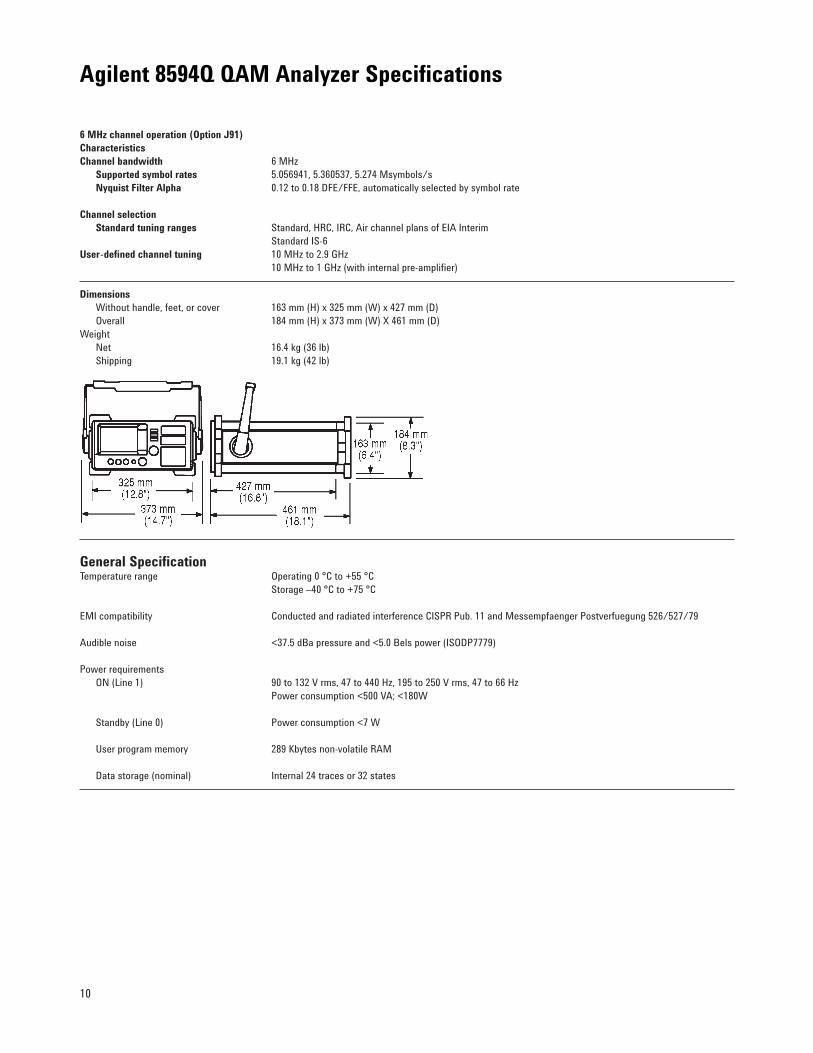
6 MHz channel operation (Option J91) CharacteristicsChannel bandwidth 6 MHz
Supported symbol rates 5.056941, 5.360537, 5.274 Msymbols/s Nyquist Filter Alpha 0.12 to 0.18 DFE/FFE, automatically selected by symbol rate
Channel selectionStandard tuning ranges Standard, HRC, IRC, Air channel plans of EIA Interim
Standard IS-6 User-defined channel tuning 10 MHz to 2.9 GHz
10 MHz to 1 GHz (with internal pre-amplifier)
DimensionsWithout handle, feet, or cover 163 mm (H) x 325 mm (W) x 427 mm (D) Overall 184 mm (H) x 373 mm (W) X 461 mm (D)
Weight Net 16.4 kg (36 lb) Shipping 19.1 kg (42 lb)
General Specification Temperature range Operating 0 °C to +55 °C
Storage –40 °C to +75 °C
EMI compatibility Conducted and radiated interference CISPR Pub. 11 and Messempfaenger Postverfuegung 526/527/79
Audible noise <37.5 dBa pressure and <5.0 Bels power (ISODP7779)
Power requirements ON (Line 1) 90 to 132 V rms, 47 to 440 Hz, 195 to 250 V rms, 47 to 66 Hz
Power consumption <500 VA; <180W
Standby (Line 0) Power consumption <7 W
User program memory 289 Kbytes non-volatile RAM
Data storage (nominal) Internal 24 traces or 32 states
Agilent 8594Q QAM Analyzer Specifications
11
Ordering Information8594Q QAM Analyzer
Option 1901 DVB-C RF and modulation quality measurements (includes DVB-C measurement software, precision frequencyreference, GPIB/parallel interface)
Option J912 6 MHz channel operation (includes RF and modulation quality measurement software, precision frequency ref-erence, GPIB/parallel interface)
Option 1953 Data measurements Option 016 Soft yellow operating/carrying case Option 040 Front panel protective cover w/storage Option 042 Protective soft carrying case Option 043 Replace GPIB/parallel interface with RS232/parallel interface Option 908 Rack mount kit without handles Option 909 Rack mount with handles Option 910 Additional manual set
Related test equipment E4441A DVB QAM Coder E443xA Series digital signal generators 89441A 2.65 GHz vector signal analyzer
Option AYA Vector modulation analysis Option AYH Digital video modulation analysis Option UFG 4 Mbytes extended RAM and additional I/O
8591C Cable TV Analyzer, 1.8 GHz, 75-ohm input (includes digital carrier power measurement)
CaLan 3010R/H Sweep/Ingress Analyzer (includes digital carrier power measurement)
E6277A MPEGScope DVB Plus
Recommended Agilent accessories 85702A 128K RAM card 85704A 256K RAM card 85705A 512K RAM card 85901A Portable AC power source 24542U RS-232 9-pin cable (analyzer to PC) 24542G RS-232 9-pin to 25-pin cable (analyzer to PC) C2950A Parallel 36-pin to 25-pin cable (analyzer to printer) 10833A GP-IB cable (1 m)
For further information on the 8594Q QAM analyzer the following literature may beordered:
Agilent 8594Q QAM Analyzer, photo card 5965-3210EAgilent 8594Q QAM Analyzer, product note 5965-4991E
Visit the interactive demo page on the World Wide Web atwww.agilent.com/info/agilent8594Q_demo
For further information on associated test equipment the following literature may beordered:
Agilent E4441A DVB QAM Coder, product information 5965-4722E Agilent Calan 8591C Cable TV Analyzer 5964-0244E Agilent CaLan 3010R/H Sweep/Ingress Analyzer 5965-1108E Agilent 89440A Option AYH Vector Signal Analyzer,
product information 5964-3403EMPEGScope DVB Plus, product information 5965-8194E
Agilent Technologies’ Test and MeasurementSupport, Services, and AssistanceAgilent Technologies aims to maximize the value you receive, while minimizingyour risk and problems. We strive toensure that you get the test and measure-ment capabilities you paid for and obtainthe support you need. Our extensive sup-port resources and services can help youchoose the right Agilent products for yourapplications and apply them successfully.Every instrument and system we sell has a global warranty. Support is available for at least five years beyond the produc-tion life of the product. Two conceptsunderlie Agilent’s overall support policy:“Our Promise” and “Your Advantage.”
Our Promise“Our Promise” means your Agilent testand measurement equipment will meet itsadvertised performance and functionality.When you are choosing new equipment,we will help you with product informa-tion, including realistic performance spec-ifications and practical recommendationsfrom experienced test engineers. Whenyou use Agilent equipment, we can verifythat it works properly, help with productoperation, and provide basic measurementassistance for the use of specified capabil-ities, at no extra cost upon request. Manyself-help tools are available.
Your Advantage“Your Advantage” means that Agilentoffers a wide range of additional experttest and measurement services, which youcan purchase according to your uniquetechnical and business needs. Solve prob-lems efficiently and gain a competitive edgeby contracting with us for calibration, extra-cost upgrades, out-of-warranty repairs, andon-site education and training, as well as design, system integration, project man-agement, and other professional services.Experienced Agilent engineers and techni-cians worldwide can help you maximizeyour productivity, optimize the return oninvestment of your Agilent instruments andsystems, and obtain dependable measure-ment accuracy for the life of those products.
Get assistance with all your test and measurement needs at: www.agilent.com/find/assist
Product specifications and descriptions in this document subject to change without notice.
Copyright © 1998, 2000 Agilent TechnologiesPrinted in U.S.A. 6/005965-5826E