Embed Size (px)
Citation preview

CRS-14-7
2009, September 09th
AGREEMENT
CONCERNING THE ADOPTION OF UNIFORM TECHNICAL PRESCRIPTIONS FOR WHEELED VEHICLES, EQUIPMENT AND PARTS WHICH CAN BE FITTED
AND/OR BE USED ON WHEELED VEHICLES AND THE CONDITIONS FOR RECIPROCAL RECOGNITION OF APPROVALS GRANTED ON THE BASIS OF THESE PRESCRIPTIONS ∗∗∗∗/
Regulation No. FRENCH DRAFT
UNIFORM PROVISIONS CONCERNING THE APPROVAL OF CHILD RESTRAINT SYSTEM USED ONBOARD OF MOTOR VEHICLES.
UNITED NATIONS
∗/ Former title of the Agreement: Agreement Concerning the Adoption of Uniform Conditions of Approval and Reciprocal Recognition of Approval for Motor Vehicle Equipment and Parts, done at Geneva on 20 March 1958. **/ For New Zealand, the entry into force is 20 April 2002.


Regulation No. FRENCH DRAFT page 3
Regulation No. FRENCH DRAFT UNIFORM PROVISIONS CONCERNING THE APPROVAL OF CHILD RETRAINT SYTSEMS USED
ONBOARD OF MOTOR VEHICLES. CONTENTS
REGULATION Page AGREEMENT .......................................... ..........................1 Regulation No. XXX ................................. ..........................1
UNITED NATIONS..................................... .........................1 1. SCOPE .............................................. ....................4 2. DEFINITIONS ........................................ ....................4 3. APPLICATION FOR APPROVAL ........................... ....................5 4. MARKINGS ........................................... ....................5 5. APPROVAL ........................................... ....................5 6. GENERAL SPECIFICATIONS ............................. ....................5 7. TESTS .............................................. ................. 2827 8. TEST REPORTS ....................................... ................. 4028 9. PRODUCTION QUALIFICATION ........................... ................. 4128 10. CONFORMITY OF PRODUCTION AND ROUTINE TESTS ......... ................. 4128 11. MODIFICATION AND EXTENSION OF APPROVAL OF A CHILD R ESTAINT SYSTEM ... 4128 12. PENALTIES FOR NON-CONFORMITY OF PRODUCTION ......... ................. 4128 13. PRODUCTION DEFINITELY DISCONTINUED ................. ................. 4128 14. INFORMATION FOR USERS .............................. ................. 4128 15. TRANSITIONAL PROVISIONS ............................ ................. 4128 16. NAMES AND ADDRESSES OF TECHNICAL SERVICES RESPONSIBLE FOR CONDUCTING APPROVAL TESTS, AND OF ADMINISTRATIVE DEPARTMENTS .. ....................... 4128 Annex 1 A .......................................... ....................... 4330 Annex 1 B .......................................... ....................... 4330 Annex 2 A .......................................... ....................... 4330 Annex 2 B .......................................... ....................... 4330 Annex 3 ................ Error! Bookmark not defined. Erreur ! Signet non défini. Annex 4 ............................................ ....................... 4431 Annex 5 ............................................ ....................... 4633 Annex 6 (to be revised) ............................ ....................... 4633
Shore hardness A: 95 ± 2 at 20 ± 5 °C temperature.................... ... 5138 Figure 5 ........................................... .................... 6248
Figure 1........................................... ...................... 6552 Annex 7 ............................................ ....................... 6854 Annex 8 ............................................ ....................... 7254
Figure 2 ............ Error! Bookmark not defined. Erreur ! Signet non défini. Figure 3 ............ Error! Bookmark not defined. Erreur ! Signet non défini.
Annex 9 ............................................ ....................... 7254 Annex 10 ........................................... ....................... 7854 Annex 11 ........................................... ....................... 7854 Annex 12 ........................................... ....................... 7854 Annex 13 ........................................... ....................... 7854 Annex 14 ........................................... ....................... 7854 Annex 15 ........................................... ....................... 7854 Annex 16 ............... Error! Bookmark not defined. Erre ur ! Signet non défini.
* * *

Regulation No. FRENCH DRAFT page 4
1. SCOPE
This Regulation applies to ISOFIX universal integra l child restraint systems for child occupants of power driven vehicles.
2. DEFINITIONS
For the purposes of this Regulation,
2.1. “Child restraint system ” means a device offering the child occupant the possibility to sit on, to sit in and/or to lay in. It is so designed as to diminish the risk of injury to the wearer, in th e event of a collision or of abrupt deceleration of the vehicle, by limiting the mobility of the child’s body.
Explanation: A doing nothing scenario will lead via Reg.44 to top tethers in all sold vehicles from 26-02-2011 [HJ2], alas a solution that is connected with much misuse! Therefore, the time seems ripe to inco rporate in the New Regulation wider possibilities for ISOFIX (more con figurations will be for universal use) but as return a fixation that is les s sensible for misuse.
2.2. “ISOFIX ” is an indication for the system of connection of a child restraint to vehicles. It is based on three vehicle rigid anchorages and three corresponding rigid attachments on the child restraint. The third anchorage point, meant to limit the pitch rotation of the child restraint system, must be attached to the correspon ding third vehicle anchorage point located at the upper front of the s eat cushion base. All three vehicle anchorages are to be approved accordi ng Regulation No.14.
2.3. “NON-ISOFIX ” is an indication for the system of connection of a child restraint to vehicles meaning that for its fixation no use is made of the ISOFIX anchorage.
2.4. “Integral ” is a class indication for the retention of the ch ild occupant in the child restraint, meaning that the child is r estrained by means that make part of the child restraint (strap harnes s, shield, [HJ3]etc.).
2.5. “Non-integral ” is a class indication for the retention of the ch ild occupant in the child restraint, meaning that the c hild has to be restrained by means not making part of this child r estraint (adult safety belt, etc.).
2.6. “IUI ” (Integral Universal Isofix CRS) is a category ind ication for a
child restraint meaning it is for use in all vehicl es, not necessarily on all vehicle positions, approved according Regula tion No.16 including its suitability for such a category of child restra int.
To remind people that the New Regulation and Regula tion.44 could be next to each other for some time (and certainly the child r estraints on the market!), hereby is the suggestion to use for the c ategory indication “UNIVERSAL” the word “IUI”. Furthermore, having in mind that Reg.44 has 5 categories (Universal, Semi-Universal, Specific Veh icle, Restricted and Special Needs) hereby is also suggested to keep the New Regulation more simple

Regulation No. FRENCH DRAFT page 5
2.7. “Size” is a stature indication for a child restrain t providing information for which range of child occupants it i s meant. It is primarily based on stature, in order to facilitate proper use, but also based on maximum mass to provide manufacturers info rmation that is related to expected maximum loads;
2.7.1.“Size 50-74 ” for children having a stature of 50 cm to 74 cm a nd a mass that reaches up to a maximum of 9.5 kg;
2.7.2.“Size 50-80 ” for children having a stature of 50 cm to 80 cm a nd a mass that reaches up to a maximum of 11 kg;
2.7.3.“Size 74-98 ” for children having a stature of 74 cm to 98 cm a nd a mass that reaches up to a maximum of 14.5 kg;
2.7.4.“Size 98-114 ” for children having a stature of 98 cm to 114 cm and a mass that reaches up to a maximum of 23 kg;
2.7.5.“Size 114-[140] ” for children having a stature of 114 cm to [140] cm and a mass that reaches up to a maximum of [34] kg;
2.7.6.Child restraint systems may cover more than o ne size provided that all requirements are fulfilled.
[HJ4] 6. 2. 2.8. “Orientation ” is the indication that a child restraint system c an be
used forward-facing and/or rearward-facing, the fol lowing distinction is made:
• forward-facing means facing in the normal direction of travel of the vehicle;
• rearward-facing means facing in the direction oppos ite to the normal direction of travel of the vehicle.
2.9. “Anti-rotation device” is a mean to avoid rotation along the two lower
ISOFIX anchorage points (e.g. top tether or support leg) 2.10 "Special Needs Restraint" is a child restraint system designed for
children who have special needs as a result of eith er a physical or mental challenge; this device may in particular per mit additional restraining devices for any part of the child, but it must contain as a minimum a primary means of restraint which complies with the requirements of this Regulation.
3. APPLICATION FOR APPROVAL
4. MARKINGS [HJ5]
5. APPROVAL
6. GENERAL SPECIFICATIONS 6.1. Positioning and securing on the vehicle 6.1.1. The use of child restraints in the ""IUI" category is permitted in the front and rearany seat positions
if the child restraints are fitted in conformity with the vehicle manufacturer's instructions.

Regulation No. FRENCH DRAFT page 6
The use of child restraints in the "specific vehicle" category is permitted only for ISOFIX CRS in all seat positions and also in the luggage area if the restraints are fitted in conformity with the vehicle manufacturer's instructions. [HJ6] 6.1.2. According to the category which it belongs to, the child restraint shall be secured to the vehicle
structure or to the vehicle seat structure. POSSIBLE CONFIGURATIONS FOR APPROVAL TYPE / CATEGORIES TABLE
TYPE / CATEGORY Universal ISOFIX CRS (IUI) (1)
Semi-universal ISOFIX CRS
Restricted ISOFIX CRS
Specific Vehicle ISOFIX CRS
Lateral facing (Carry-cot)
A NA
A
A
Rearward facing A NA
A
A
Forward facing (integral)
A NA
A
A
Forward facing (non integral)
NA
NA
NA
NA [HJ7]
With: CRS: Child restraint system A: Applicable NA: Not Applicable ______________________ (1)IUI CRS means forward, rearward or lateral facing restraints for use in vehicles with positions equipped with ISOFIX anchorages system and an anti-rotation device (e.g. top tether anchorage or a support leg). 6.1.2.1. For ISOFIX "universal" integral child restraint systems (IUI) by means of ISOFIX attachments
and an anti-rotation device (e.g. ISOFIX top tether strap or support leg meeting the requirements of this Regulation fitted to ISOFIX anchorages system and ISOFIX top tether anchorage [or vehicle floor][HJ8] meeting the requirements of Regulation No. 14).
6.1.2.2. For the ISOFIX "specific vehicle" category: by means of the ISOFIX anchorages designed by
the manufacturer of the vehicle or the manufacturer of the child restraint; 6.2.1.6.1.3. The child restraint manufacturer has to declare in written form that the toxicity of materials
used in the manufacture of restraint systems and accessible to the restrained child is in
Regulation No. FRENCH DRAFT page 7
conformity with the relevant parts of CEN Safety of Toys, part 3 (June 1982). 1/ Tests confirming the validity of the declaration may be carried out at the discretion of the test authority.
6.2.2.6.1.4. The child restraint manufacturer has to declare in written form that the flammability of
materials used to manufacture the restraint system is in conformity with the relevant paragraphs of the ECE Consolidated Resolution on the Construction of Vehicles (R.E.3) (document TRANS/WP.29/78/Rev.1, paragraph 1.20.). Tests confirming the validity of the declaration may be carried out at the discretion of the test authority.
Child restraints of groups 0 and 0+ shall not be used forward facing.[HJ9]
6.1.5 For children under the age of [1815[HJ10]] months only carry-cot or rearward facing CRS must be used. The use of rearward facing CRS is authorised for any age.
6.2.3.6.1.5. Child restraint systems of groups 0, 0 +, 1, with the exception of carry cots as defined in
paragraph 2.4.1., shall belong to the integral class. 6.1.6. With the exception of carry cots as defined in paragraph 2.4.1., all
child restraint systems defined for sizes smaller t han [105 cm] shall belong to the integral class.
[HJ11] 2.1.6.2 Configuration of the Child Restraint 2.1.1.6.2.1. The configuration of the child restraint shall be such that 2.1.1.1.6.2.1.1. The restraint of the child shall give the required
protection in any intended position of the child restraint system; for "Special Needs Restraints" the primary means of restraint shall give the required protection in any intended position of the child restraint system without the use of the additional restraining devices which may be present.
2.1.1.2.6.2.1.2. The child is easily and quickly installed [HJ12]and
removed; in the case of a child restraint system in which the child is restrained by means of a harness belt or a Y-shaped belt without a retractor each shoulder restraint and lap strap shall be capable of movement relative to each other during the procedure prescribed in paragraph 7.2.1.4.
In these cases the belt assembly of the child restraint may be designed with two or more
connecting parts. For "Special Needs Restraints" it is recognized that the additional
1/ The address to obtain the relevant CEN standards is: CEN, 2 rue Bréderode, B.P. 5, B 1000 Bruxelles, Belgium.

Regulation No. FRENCH DRAFT page 8
restraining devices will restrict the speed by which a child can be installed [HJ13]and removed. However, the additional devices shall be designed to release quickly so far as possible.
2.1.1.3.6.2.1.3. If it is possible to change the inclination of the child
restraint system, this change in inclination shall not require manual readjustment of the child restraint harness. A deliberate hand-action is required in order to change the inclination of the child restraint system.
2.1.1.4.6.2.1.4. The groups 0, 0+ and I restraint systems shall keep
the child so positioned as to give the required protection even when the child is asleep 2.1.1.5.6.2.1.5. To prevent submarining, either by impact or through
restlessness, a crotch strap shall be required on all forward-facing group I restraints incorporating an integral harness belt system. With the crotch strap attached and in its longest position if adjustable, it shall not be possible to adjust the lap strap to lie above the pelvis in either the 9 kg or the 15 kg of the dummy.
6.2.1.6. To prevent excessive rotation an anti-rotation device shall be required on all forward and
rearward facing child restraint systems. 6.2.1.7 The assembly shall not subject weak parts of the child's body (abdomen, crotch, etc.) to
excessive stresses. The design shall be such that compression loads shall not be imposed on the crown of the child's head in the event of a collision.
2.1.2.6.2.2. The child restraint system shall be so designed and installed as: 2.1.2.1.6.2.2.1. not to exhibit sharp edges or protrusions liable to
cause damage to vehicle-seat covers or to occupant's clothing; 2.1.2.2.6.2.2.2. to ensure that its rigid parts do not, at points where
they are in contact with straps, exhibit sharp edges capable of abrading the straps. 2.1.3.6.2.3. Any components shall be so designed as to avoid any risk of incorrect assembly and use. Any
separable part shall need special tools to be detached or fixed.[HJ14] "Special Needs Restraints" may have additional restraining devices; these shall be designed to avoid any risk of incorrect assembly and that their means of release and mode of operation is immediately obvious to a rescuer in an emergency.
2.1.4.6.2.4. Only automatically-locking retractors or emergency-locking retractors may be used. 2.1.5.6.2.5. For devices intended for use in Group I it must not be possible for the child to easily slacken
that part of the system that restrains the pelvis after the child has been installed; afor this purpose the requirements of paragraph 7.2.5. (lock-off devices) shall be fulfilled; any device that is designed to obtain this must be permanently attached to the child restraint system.[HJ15]

Regulation No. FRENCH DRAFT page 9
2.1.6.6.2.6. A child restraint system may be designed for use in range of size specified by the manufacturer, provided that it is able to satisfy the requirements laid down in this regulation..[HJ16]
2.1.7.6.2.7. Child restraints with retractor
In the case of a child restraint incorporating a retractor, the retractor shall have met the requirements of paragraph 7.2.3.
2.2.6.3. ISOFIX restraint specifications 2.2.1.6.3.1. General characteristics 2.2.1.1.6.3.1.1. Dimensions
The maximum lateral, downward, and rearward dimensions for the ISOFIX child restraint system and the locations of the ISOFIX anchorages system with which its attachments must engage are defined for the ISOFIX child restraint system manufacturer by the Vehicle Seat Fixture (VSF) defined by paragraph 2.31. of this Regulation.
[HJ17] 2.2.1.2.6.3.1.2. Mass
The mass of an ISOFIX child restraint system associated of the mass of the biggest child intended to use the child restraint system shall not exceed [32] kg.[HJ18]
2.2.2.6.3.2. ISOFIX Attachments 2.2.2.1.6.3.2.1. Type
ISOFIX Attachments may be according to examples shown in Figure 0 (a), or other appropriate designs that are part of a rigid mechanism having provision for adjustment, the nature of which is determined by the ISOFIX child restraint system manufacturer.

Regulation No. FRENCH DRAFT page 10
Dimensions in mm
Figure 0 (a) Key 1 ISOFIX child restraint system attachment - example 1 2 ISOFIX child restraint system attachment - example 2 2.2.2.2.6.3.2.2. Dimensions
Dimensions for the portion of the ISOFIX child restraint system attachment that engages the ISOFIX anchorage system must not exceed the maximum dimensions given by the envelope in figure 0 (b)
Dimensions in mm

Regulation No. FRENCH DRAFT page 11
Figure 0 (b) 2.2.2.3.6.3.2.3. Partial latching indication The ISOFIX child restraint system shall incorporate means by which there is a clear indication that both of the ISOFIX attachments are completely latched with the corresponding ISOFIX lower anchorages. The indication means may be audible, tactile or visual or a combination of two or more. In case of visual indication it must be detectable under all normal lighting conditions. 2.2.3.6.3.3. ISOFIX child restraint top tether strap specifications 2.2.3.1.6.3.3.1. Top tether connector The top tether connector should be ISOFIX top tether hook as shown in figure 0 (c), or similar devices that fit within the envelope given by figure 0 (c). 2.2.3.2.6.3.3.2. ISOFIX Top tether strap features The ISOFIX top tether strap shall be supported by webbing (or its equivalent), having a provision for adjustment and release of tension. 6.3.3.2.1. ISOFIX Top tether strap length ISOFIX Child restraint top tether strap length shall be at least 2,000 mm. 6.3.3.2.2. No-slack indicator The ISOFIX top tether strap or the ISOFIX child seat shall be equipped with a device that will indicate that all slack has been removed from the strap. The device may be part of adjustment and tension relieving device. 6.3.3.2.3. Dimensions Engagement dimensions for ISOFIX top tether hooks are shown in figure 0 (c).

Regulation No. FRENCH DRAFT page 12
Figure 0 (c): ISOFIX Top tether connector (hook type) dimensions 6.3.4. ISOFIX child restraint support leg specifications
See ISO definition and recommendations 6.3.5. Adjustment provisions
The ISOFIX attachments, or the ISOFIX child restraint system itself, shall be adjustable to accommodate the range of ISOFIX anchorage locations and/or vehicle floor described in Regulation No. 14 (following ISO recommendations).[HJ19]
6.4. Control of Markings

Regulation No. FRENCH DRAFT page 13
6.4.1. The Technical Service conducting the approval tests shall verify that the markings conform to
the requirements of paragraph 4. 6.5. Control of Instructions on Installation and the Instructions for Use 6.5.1. The Technical Service conducting the approval tests shall verify that the instructions on
installation and the instructions for use conform to paragraph 15. 6.6. Provisions applicable to the assembled child restraint system 6.6.1. Resistance to corrosion 6.6.1.1. A complete child restraint system, or the parts thereof that are liable to corrosion, shall be
subject to the corrosion test specified in paragraph 7.1.1. below. 6.6.1.2. After the corrosion test as prescribed in paragraphs 7.1.1.1. and 7.1.1.2., no signs of
deterioration likely to impair the proper functioning of the child restraint system, and no significant corrosion, shall be visible to the unaided eye of a qualified observer.
6.6.2. Energy absorption 6.6.2.1. For all devices with backrests there shall be internal surfaces, defined in Annex 18 to this
Regulation, comprising material with a peak acceleration of less than 60 g when measured in accordance with Annex 17 to this Regulation. This requirement applies also to areas of impact shields which are in the head strike area.
6.6.2.2. In the case of child restraint systems with permanent mechanically attached adjustable head
support devices, in which the height of either the adult safety-belt or of the child harness is directly controlled by the adjustable head support, it is not necessary to demand energy absorbing material in areas as defined in Annex 18, which are not contactable by the manikin’s head, i.e. behind the head support.
[HJ20] 6.6.3. Overturning 6.6.3.1. The child restraint shall be tested as prescribed in paragraph 7.1.2.; the manikin shall not fall
out of the device and, when the test seat is in the upside down position the manikin's head shall not move more than 300 mm from its original position in a vertical direction relative to the test seat.
6.6.4. Dynamic test
Remarks from Hans Ammerlaan - NL MOT/RDW
• this piece of work is focussed on rewriting the frontal and rear impact; • to keep an overview nothing of the old text is deleted but in strikethrough characters; • for the same reason the old numbering is up to now not changed; • because later also child restraints tested with Q3, Q6 and Q10 are supposed to make part of the new
regulation, an open mind is kept with regard to their applications too;

Regulation No. FRENCH DRAFT page 14
• what is added or replaced is put in a coloured frame; • to provide a first reasoning behind the changes, extra text in Italics is used; • the term of iSize child restraint is hereby introduced what should be pronounced in the same way as e.g.
the word “iPod”; • iSize is an indication as the word group in Reg.44 and it means that for the way of choosing child
restraint one should primarily use ones eyes and take account of the stature of the child; • iSize also means that it concerns child restraints that are fastened by means of iSOFIX; • we could try to develop this new child restraint regulation for all child restraints that are fixed by means
of the ISOFIX anchorages; • that is to say iSize child restraints could also mean e.g. boosters and boosters+backrests that are
restrained with the well-known anchorages (but the children with adult belts); • the UNECE Reg.44 could be kept for all child restraints that do not make use of ISOFIX and where their
fixation (location and which way) is less traceable and alas the outcome of accidents too!
6.6.4.1. General. The child restraint shall be subjected to a dynamic tests in conformity with paragraph
8.1.3. below. Remark: paragraph 8.1.3. must be extended with “Description of the side impact test” and this paragraph 7 must be extended with the particular specifications of the side impact test.
6.6.4.1.1. Child restraints of the "universal" , "restricted" and "semi-universal" categories category shall
be tested on the test trolley by means of the test seat prescribed in paragraph 6., and in conformity with paragraph 8.1.3.1.
6.6.4.1.2. Child restraints of the "specific vehicle" category shall be tested with each vehicle model for
which the child restraint is intended. The Technical Service responsible for conducting the test may reduce the number of vehicle models tested if they do not differ greatly in the aspects listed in paragraph 7.1.4.1.2.3. The child restraint may be tested in one of the following ways:
6.6.4.1.2.1. On a complete vehicle, as prescribed in paragraph 8.1.3.3.; 6.6.4.1.2.2. In a vehicle body shell on the test trolley, as prescribed in paragraph 8.1.3.2.; or, 6.6.4.1.2.3. In sufficient parts of the vehicle bodyshell to be representative of the vehicle structure and
impact surfaces. If the child restraint is intended for use in the rear seat, these shall include the back of the front seat, the rear seat, the floor pan, the B and C pillars and the roof. If the child restraint is intended for use in the front seat, the parts shall include the dashboard, the A pillars, the windscreen, any levers or knobs installed in the floor or on a console, the front seat, the floor pan and the roof. Furthermore, if the child restraint is intended for use in combination with the adult safety belt, the parts shall include the appropriate adult belt(s). The Technical Service responsible for conducting the test may permit items to be excluded if they are found to be superfluous. Testing shall be as prescribed in paragraph 8.1.3.2.
6.6.4.1.3. The dynamic test shall be performed on child restraints which have not previously been under
load.
Regulation No. FRENCH DRAFT page 15
7.1.4.1.4. During the dynamic tests, no part of the child restraint actually helping to keep the child in position shall break, and no buckles or locking system or displacement system shall release.
Remark: must be placed in the part with criteria of the dynamic test!! 7.1.4.1.5. In the case of "non-integral type" the seat belt used shall be the standard belt and its anchorage
brackets prescribed in Annex 13 to this Regulation. This does not apply to "specific vehicle" approvals where the actual belt of the vehicle shall be used.
Remark: because iSize child restraints could also mean boosters for heavier children where only the CRS is held by the ISOFIX anchorages and the child by the adult belt, this paragraph must return in some way. 6.6.4.1.4. If a "specific vehicle" child restraint system is installed in the area behind the rearmost
forward facing adult seat positions (for example, the luggage area), one test with the largest dummy/dummies on a complete vehicle as prescribed in paragraph 8.1.3.3.3. shall be performed. The other tests, including the conformity of production, may be done as prescribed in paragraph 8.1.3.2., if the manufacturer so wishes.
6.6.4.1.5. In the case of a "Special Needs Restraint" every dynamic test specified by this Regulation for
each mass group shall be performed twice: first, using the primary means of restraint and second, with all restraining devices in use. In these tests, special attention shall be given to the requirements in paragraphs 6.2.3. and 6.2.4.
7.1.4.1.8. During the dynamic tests, the standard safety-belt used to install the child restraint shall
not become disengaged from any guide or locking device utilised for the test conducted. Remark: this paragraph must return is some way in the part with criteria of the dynamic test, because iSize child restraints could also mean boosters (with backrests!) for heavier children where the CRS is “held” by the ISOFIX anchorages but where the diagonal part of the adult belt receives some guidance from the backrest for an improved fitting of the child. 6.6.4.1.6. In the case of an iSize A child restraint with a support leg shall be tested as an anti-rotation
device the hereafter mentioned dynamic tests shall be carried out as follows:
a) In the case of semi-universal category, the tests for frontal impact shall be conducted with the support leg adjusted to both its maximum and minimum adjustment compatible with the positioning of the trolley floor pan[HJ21]. The tests for rear impact shall be conducted with the worst case position selected by the Technical Service. During the tests the support leg shall be supported by the trolley floor pan as described in Annex 6, Appendix 3, Figure 2. If there is clearance between the shortest leg length and the highest floor pan level, the leg is adjusted to the floor pan level of 140 mm below Cr. If the maximum leg length is more than the lowest floor pan level would allow to be used, the leg is adjusted to that lowest floor pan level of 280 mm below Cr. In the case of support leg with adjustable steps, the support leg length shall be adjusted to the next adjustment position, in order to ensure the support leg is in contact with the floor.

Regulation No. FRENCH DRAFT page 16
b) In the case of support legs out of the plane of symmetry, the worst case shall be selected by the Technical Service for the test.
c) In the case of specific vehicle category, the support leg shall be adjusted as
specified by the child restraint manufacturer.
Remark: the added next two subparagraph’s are for this moment mentioned in this summing up because they mean a different set up for the dynamic test. However in fact these two subparagraph’s contain requirements for ISOFIX child restraints with a support leg and should be placed in the updated paragraph 6 e.g.where the configuration is dealt with. Here a paragraph 6.2.1.5. already exists and starts with “To prevent submarining ..”; well, the requirements on support legs could be clustered in a new paragraph that will start with the heading 6.2.1.6. “To prevent rotational accelerations …” .
d) the leg length of a support leg must be adjustable in such a way that it is able to
cover the complete span of floor pan levels that are allowed for in Regulation No.16, Annex 17 for car seats to be approved for the installation of ISOFIX child restraints systems.
Remark: consequently Regulation No.16, Annex 17 have to be adapted to safeguard that the span of floor heights at the car seats equiped with ISOFIX, will stay between the borders that can be covered by the iSize child restraints.
e) the complete support leg must be permanently attached to the child restraint or
attached to the part of the child restraint that will be fixed directly to the lower anchorage bars .
6.6.4.1.7. In the case of an iSize child restraint making use of an ISOFIX anchorage system and a top
tether strap as an anti-rotation device, if any, the dynamic test shall be carried out as follows: 7.1.4.1.10.1. For ISOFIX CRS of size classes A and B: 6.6.4.1.7.1. With the anti-rotation device in use, and 6.6.4.1.7.2. Without the anti-rotation device in use. This requirement does not apply when a
permanent and non-adjustable support leg is used as an anti-rotation device. 7.1.4.1.10.2. For ISOFIX child restraint system of other size classes with the anti-rotation device in
use. 7.1.4.2. Chest acceleration 2/
2/ Chest acceleration limits do not apply when using the "new born" manikin as it is not instrumented.

Regulation No. FRENCH DRAFT page 17
7.1.4.2.1. The resultant chest acceleration shall not exceed 55 g except during periods whose sum does not exceed 3 ms.
7.1.4.2.2. The vertical component of the acceleration from the abdomen towards the head shall not exceed 30 g except during periods whose sum does not exceed 3 ms.
6.6.4.2. CRITERIA: During the dynamic tests, no part of the child restraint actually helping to keep the
child in position shall break, and no buckles or locking system or displacement system shall release.
Remark: this is former para. 7.1.4.1.4. however a similar clause should also be in the other dynamic test (side impact!) as this kind of failures easy leads to non containment of the child. 6.6.4.3. Dummy criteria 6.6.4.3.1. Abdominal penetration: During the verification described in Annex 8 - Appendix 1, paragraph
5.3., there shall be no visible signs of penetration of the modelling clay of the abdomen caused by any part of the restraining device.
During the frontal impact the “Resultant of Fx and Fz registrated in the lower lumbar spine shall not exceed [xx] percent of the lap belt force; this ratio shall be measured instantaneous with respect to time.
Remark: abdominal injury may not be neglected and as clay will not be anymore a “measuring tool” the focus should be on available tools that could give indications of submarining behaviour that lead to these injuries. In case of a wrong lap belt configuration (that is to say or the lap belt is positioned too high from the beginning or it will slip upwards over the Iliac wings during the frontal impact) the lower lumbar spine load cell will be extra loaded by forces acting in the direction of the impact. Namely not only by the stretching of the dummies (under)legs but also by the pelvis being more rotated when the lap belt intrudes the abdominal section. With regard to this latter point (rotation of pelvis) “angular rate sensors”, which are already used in the head, could also play a role as indicator of submarining of the pelvis. 6.6.4.3.2. Injury assessment criteria Remark: consider this table as between square brackets, explaining remarks you will find below.
Injury assessment criteria per dummy Criterion Abbreviation Q0 Q1 Q1.5 Q3 Q6 Q10 Head Impact Criterion (only in case of hard contact during in-vehicle testing)
HIC 523 - 671
491 - 629
578 - 741
780 - 1000
1083 - 1389
Head Acceleration 3ms A head 3ms 85 72 76 81 89 Upper Neck Tension Force Fz 546 1201 1364 1705 2304 Upper Neck Flexion Moment My 17 53 61 79 118 Thorax Chest Deflection D chest NA 40 38 36 33 Chest Acceleration 3 ms A chest 3ms 55 55 55 55 55

Regulation No. FRENCH DRAFT page 18
Explaining remarks: The final determination of the injury assessment criteria should lead to child restraints that are significantly better than those child restraints that are just fulfilling the Reg.44 criteria. HIC: the herewith presented injury assessment criteria are given as a window and vary between the values that count for 20% and 50% chance on AIS 3+ LR injury, and as stated are only intended for judgement of hard contact during in-vehicle testing; A 3 ms: these are from AIS 3+ 20 % LR injury. Less than 10 % of CRSs tested in the EEVC work failed these criteria. This seems a reasonable level. Fz: Using AIS 3+ 50% injury (read from page 109) of the CRSs tested in the EEVC work still failed this. This seems a difficult level to meet. My: these are from the AIS 3+ 20% LR injury criteria. All CRSs seem to be succesful with regard to these criteria. D chest: these are from the AIS 3+ 20% injury, and 20% of the products tested in the EEVC work would have failed these criteria. Taking account of the fact that this is a new criterion for CRS-testing this seems promissing. A chest 3 ms: for this criterion, there seems to exist some correlation between what is measured with P dummies and Q-dummies. Therefore this criterion is also mentioned in the table above. 6.6.4.4. 7.1.4.4.Manikin’s head displacement 6.6.4.4.1. Child restraints of the "universal", "restricted" and "semi-universal" categories: 6.6.4.4.1.1. Forward facing child restraints: Head excursion: no part of the head of the manikin shall not pass beyond the planes BA,
and DA and DE as defined in Figure 1 below. This shall be judged up to 300 ms or the moment that the manikin has come to a definitive standstill whatever occurs first.
Remark: as is the case with rearward facing child restraints, the point E being the top of the seat back of the R.44 seat should also be defined here. Furthermore, because it concerns ISOFIX child restraints, the forward excursion limit shall have to be changed from 550 mm to 500 mm. Finally, the 800 mm vertical limit shall have to be connected to only testing with Q0, Q1, Q1.5, Q3 and Q6, whilst for testing with Q10 a vertical limit of 840 mm will be used.

Regulation No. FRENCH DRAFT page 19
Dimensions in mm
Figure 1 - Arrangement for testing a forward-facing device
7.1.4.4.1.2. Rear-facing child restraints: 7.1.4.4.1.2.1. Child restraints supported by dashboard: the head of the manikin shall not pass beyond the
planes AB, AD and DCr, as defined in Figure 2 below. This shall be judged up to 300 ms or the moment that the manikin has come to a definitive standstill whatever occurs first.
Remark: figure below with support by dashboard not needed anymore must be deleted

Regulation No. FRENCH DRAFT page 20
7.1.4.4.1.2.2. Child restraints in group 0 not supported by the dashboard, and carrycots: the head of the manikin shall not pass the planes AB, AD and DE as shown in Figure 3 below. This shall be judged up to 300 ms or the moment that the manikin has come to a definitive standstill whatever occurs first.
Remark: figure below with distance of 600 not needed anymore must be deleted
Figure 2: Arrangement for testing a rearward-facing device
Dimensions in mm
Steel tube

Regulation No. FRENCH DRAFT page 21
Figure 3 - Arrangement for testing child restraint devices group 0,
not supported by the dashboard 6.6.4.4.1.2. Rearward-facing child restraints and carrycots: 6.6.4.4.1.2.1. Head exposure: during the dynamic tests the head must remain fully contained within the
child restraint shell (i.e. the top of the head.must not be exposed to the possibility of direct contact with surfaces of the vehicle).
7.1.4.4.1.2.3. Child restraints other than group 0 not supported by the dashboard: 6.6.4.4.1.2.2. Head excursion: no part of the head of the manikin shall not pass beyond the planes FD,
FG and DE, as shown in Figure 4 below. This shall be judged up to 300 ms or the moment that the manikin has come to a definitive standstill whatever occurs first.
In the case there is a contact of such a child restraint with the 100 mm diameter bar and
all performance injury assessment and manikin’s head displacement criteria are met, there shall be one further dynamic test (front impact) with the heaviest dummy intended for such child restraint the given iSize indication and without the 100 mm diameter bar; the requirements for this test are that all criteria other than forward displacement the criteria of paragraph 7.1.4.2. (child restraint integrity) and paragraph 7.1.4.4.1.2.1. (head exposure) are met.

Regulation No. FRENCH DRAFT page 22
Remark: now from the point of view that a distance from Cr point to dashboard of 700 mm will be an accepted measure, it should be safeguarded that front passenger car seats can offer this space (after normal adjustment of the seat).
6.6.4.4.2. Child restraints of the "specific vehicle" category: when tested in a complete vehicle
or a vehicle body shell, the head shall not come into contact with any part of the vehicle. However, if there is contact, the speed of impact of the head shall be less than 24 km/h and the part contacted shall meet the requirements of the energy absorption test laid down in Regulation No. 21, Annex 4. the head impact criterion HIC and the Head Acceleration 3ms shall be used as assessment criteria. In tests with complete vehicles it shall be possible to remove the manikins from the child restraint without the use of tools after the test.
6.6.5. Resistance to temperature
800
380
700
D
C r
F
G
E
Dimensions in mm
Figure 4:Arrangement for testing rearward-facing devices, except group 0,
not supported by the dashboard
Steel tube
500 x �100 x �90Steel tube 500 x ∅100 x ∅90

Regulation No. FRENCH DRAFT page 23
6.6.5.1. Buckle assemblies, retractors, adjusters and lock-off devices that are liable to be affected by
temperature, shall be subject to the temperature test specified in paragraph 8.2.8. below. 6.6.5.2. After the temperature test as prescribed in paragraph 8.2.8.1., no signs of deterioration likely to
impair the proper functioning of the child restraint, shall be visible to the unaided eye of a qualified observer.
6.7. Provisions applicable to individual components of the restraint 6.7.1. Buckle 6.7.1.1. The buckle shall be so designed as to preclude any possibility of incorrect manipulation. This
means, inter/alia, that it must not be possible for the buckle to be left in a partially closed position; it must not be possible to exchange the buckle parts inadvertently when the buckle is being locked; the buckle must only lock when all parts are engaged. Wherever the buckle is in contact with the child, it shall not be narrower than the minimum width of strap as specified in paragraph 7.2.4.1.1 below. This paragraph is not applicable to belt assemblies already approved according to ECE Regulation No. 16 or any equivalent standard in force. In the case of a "Special Needs Restraint" only the buckle on the primary means of restraint need comply with the requirements of paragraphs 7.2.1.1. to 7.2.1.9. inclusive.
6.7.1.2. The buckle, even when not under tension, shall remain closed whatever its position. It shall be
easy to operate and to grasp. It shall be possible to open it by pressure on a button or on a similar device. The surface to which this pressure must be applied must have in the position of actual unlocking and when projected into a plane perpendicular to the button's initial direction of motion: for enclosed devices, an area of not less than 4.5 cm2 with a width of not less than 15 mm; for non-enclosed devices, an area of 2.5 cm2 and a width of not less than 10 mm. The width shall be the smaller of the two dimensions forming the prescribed area and shall be measured rectangular to the direction of movement of the release button.
6.7.1.3. The buckle release area shall be coloured red. No other part of the buckle shall be of this
colour. 6.7.1.4. It shall be possible to release the child from the restraint by a single operation on a single
buckle. For groups 0 and 0+ it is allowed to remove the child together with devices such as infant carrier/carry-cot/carry-cot restraints if the child restraint system can be released by operation of a maximum of two buckles.
6.7.1.4.1. A clip connection between the shoulder straps of a harness belt is deemed not to comply with
the single operation requirement given in paragraph 7.2.1.4. above. 6.7.1.5. For groups II and III the buckle shall be so placed that the child occupant can reach it. In
addition it shall for all groups be so placed that its purpose and mode of operation are immediately obvious to a rescuer in an emergency.
6.7.1.6. Opening of the buckle shall enable the child to be removed independently of the "chair", "chair support" or "impact shield", if fitted, and if the device includes a crotch strap the crotch strap shall be released by operation of the same buckle.

Regulation No. FRENCH DRAFT page 24
6.7.1.7. The buckle shall be capable of withstanding the temperature test operation requirements given
in paragraph 8.2.8.1. and repeated operation, and shall, before the dynamic test prescribed in paragraph 8.1.3. undergo a test comprising 5,000 ± 5 opening and closing cycles under normal conditions for use.
6.7.1.8. The buckle shall be subjected to the following tests of opening: 6.7.1.8.1. Test under load 6.7.1.8.1.1. A child restraint having already undergone the dynamic test prescribed in paragraph 8.1.3.
below shall be used for this test. 6.7.1.8.1.2. The force required to open the buckle in the test prescribed in paragraph 8.2.1.1. below shall
not exceed 80 N. 6.7.1.8.2. No-load test 6.7.1.8.2.1. A buckle which has not previously been subjected to a load shall be used for this test. The
force needed to open the buckle when it is not under load shall be in the range of 40-80 N in the tests prescribed in paragraph 8.2.1.2.
6.7.1.9. Strength. 6.7.1.9.1. During the test in accordance with paragraph 8.2.1.3.2. no part of the buckle or the adjacent
straps or adjusters shall break or be detached. 6.7.1.9.2. A harness buckle of mass groups 0 and 0+ shall withstand 4,000 N. 6.7.1.9.3. A harness buckle of mass group I and higher shall withstand 10,000 N. 6.7.1.9.4. The competent authority may dispense with the buckle strength test if information already
available renders the test superfluous. 6.7.2. Adjusting device 6.7.2.1. The range of adjustment shall be sufficient to permit correct adjustment of the child restraint
with all manikins of the weight group for which the device is intended and to permit satisfactory installation in all specified vehicle models.
6.7.2.2. All adjusting devices shall be of the "quick adjuster" type, except that adjusting devices used
only for the initial installation of the restraint in the vehicle may be of other than the "quick adjuster" type.
6.7.2.3. Devices of the "quick adjuster" type shall be easy to reach when the child restraint is correctly
installed and the child or manikin is in position.

Regulation No. FRENCH DRAFT page 25
6.7.2.4. A device of the "quick adjuster" type shall be easily adjustable to the child's physique. In particular, in a test performed in accordance with paragraph 8.2.2.1., the force required to operate a manual adjusting device shall not exceed 50 N.
6.7.2.5. Two samples of the child-restraint adjusting devices shall be tested as prescribed by the
temperature test operation requirements given in paragraph 8.2.8.1. and in paragraph 8.2.3. 6.7.2.5.1. The amount of strap slip shall not exceed 25 mm for one adjusting device or 40 mm for all
adjusting devices. 6.7.2.6. The device must not break or become detached when tested as prescribed in paragraph 8.2.2.1. 6.7.2.7. An adjuster mounted directly on the child restraint shall be capable of withstanding repeated
operation and shall, before the dynamic test prescribed in paragraph 8.1.3. undergo a test comprising 5,000 ± 5 cycles as specified in paragraph 8.2.7.
6.7.3. Retractors 6.7.3.1. Automatically-locking retractors 6.7.3.1.1. The strap of a safety-belt equipped with an automatically-locking retractor shall not unwind
by more than 30 mm between locking positions of the retractor. After a rearward movement of the wearer the belt must either remain in its initial position or return to that position automatically on subsequent forward movement of the wearer.
6.7.3.1.2. If the retractor is part of a lap belt, the retracting force of the strap shall be not less than 7 N as
measured in the free length between the manikin and the retractor as prescribed in paragraph 8.2.4.1. below. If the retractor is part of a chest restraint, the retracting force of the strap shall be not less than 2 N or more than 7 N as similarly measured. If the strap passes through a guide or pulley, the retracting force shall be measured in the free length between the manikin and the guide or pulley. If the assembly incorporates a device, manually or automatically operated, that prevents the strap from being completely retracted, that device shall not be in operation when these measurements are effected.
6.7.3.1.3. The strap shall be repeatedly withdrawn from the retractor and allowed to retract, in the
conditions prescribed in paragraph 8.2.4.2. below, until 5,000 cycles have been completed. The retractor shall then be subjected to the temperature test operation requirements given in paragraph 8.2.8.1. and corrosion test described in paragraph 8.1.1 and the dust-resistance test described in paragraph 8.2.4.5. It shall then satisfactorily complete a further 5,000 cycles of withdrawal and retraction. After the above tests the retractor shall continue to operate correctly and to meet the requirements of paragraphs 7.2.3.1.1. and 7.2.3.1.2. above.
6.7.3.2. Emergency-locking retractors 6.7.3.2.1. An emergency-locking retractor shall when tested as prescribed in paragraph 8.2.4.3. satisfy
the conditions below: 6.7.3.2.1.1. It shall be locked when the deceleration of the vehicle reaches 0.45 g.

Regulation No. FRENCH DRAFT page 26
6.7.3.2.1.2. It shall not lock for strap accelerations of less than 0.8 g as measured in the axis of strap
extraction. 6.7.3.2.1.3. It shall not lock when its sensing device is tilted by not more than 12° in any direction from
the installation position specified by its manufacturer. 6.7.3.2.1.4. It shall lock when its sensing device is tilted by more than 27° in any direction from the
installation position specified by its manufacturer. 6.7.3.2.2. Where the operation of a retractor depends on an external signal or power source, the design
shall ensure that the retractor locks automatically upon failure or interruption of that signal or power source.
6.7.3.2.3. A multiple-sensitivity emergency-locking retractor shall meet the requirements set out above.
In addition, if one of the sensitivity factors relates to strap extraction, locking must have occurred at a strap acceleration of 1.5 g as measured in the axis of strap extraction.
6.7.3.2.4. In the tests referred to in paragraphs 7.2.3.2.1.1. and 7.2.3.2.3. above, the amount of strap
extraction occurring before the retractor locks shall not exceed 50 mm, starting at the length of unwinding specified in paragraph 8.2.4.3.1. In the test referred to in paragraph 7.2.3.2.1.2. above, locking shall not occur during the 50 mm of strap extraction starting at the length of unwinding specified in paragraph 8.2.4.3.1. below.
6.7.3.2.5. If the retractor is part of a lap belt, the retracting force of the strap shall be not less than 7 N as
measured in the free length between the manikin and the retractor as prescribed in paragraph 8.2.4.1. If the retractor is part of a chest restraint, the retracting force of the strap shall be not less than 2 N or more than 7 N as similarly measured. If the strap passes through a guide or pulley, the retracting force shall be measured in the free length between the manikin and the guide or pulley. If the assembly incorporates a device, manually or automatically operated, that prevents the strap from being completely retracted, that device shall not be in operation when these measurements are effected.
6.7.3.2.6. The strap shall be repeatedly withdrawn from the retractor and allowed to retract, in the
conditions prescribed in paragraph 8.2.4.2., until 40,000 cycles have been completed. The retractor shall then be subjected to the temperature test operation requirements given in paragraph 8.2.8.1. and corrosion test described in paragraph 8.1.1 and to the dust-resistance test described in paragraph 8.2.4.5. It shall then satisfactorily complete a further 5,000 cycles of withdrawal and retraction (making 45,000 in all). After the above tests the retractor shall continue to operate correctly and to meet the requirements of paragraphs 7.2.3.2.1. to 7.2.3.2.5. above.
6.7.4. Straps 6.7.4.1. Width 6.7.4.1.1. The minimum width at the child-restraint straps which contact the dummy shall be 25 mm for
groups 0, 0+ and I, and 38 mm for groups II and III. These dimensions shall be measured

Regulation No. FRENCH DRAFT page 27
during the strap strength test prescribed in paragraph 8.2.5.1., without stopping the machine and under a load equal to 75 percent of the breaking load of the strap.
6.7.4.2. Strength after room conditioning 6.7.4.2.1. On two sample straps conditioned as prescribed in paragraph 8.2.5.2.1., the breaking load of
the strap shall be determined as prescribed in paragraph 8.2.5.1.2. below. 6.7.4.2.2. The difference between the breaking loads of the two samples shall not exceed 10 percent of
the greater of the two breaking loads measured. 6.7.4.3. Strength after special conditioning 6.7.4.3.1. On two straps conditioned as prescribed in one of the provisions of paragraph 8.2.5.2. (except
paragraph 8.2.5.2.1.), the breaking load of the strap shall be not less than 75 percent of the average of the loads determined in the test referred to in paragraph 8.2.5.1. below.
6.7.4.3.2. In addition, the breaking load shall be not less than 3.6 kN for the restraints of the groups 0,
0+ and I, 5 kN for those of group II, and 7.2 kN for those of group III. 6.7.4.3.3. The competent authority may dispense with one or more of these tests if the composition of
the material used, or information already available, renders the test or tests superfluous. 6.7.4.3.4. The abrasion conditioning procedure of type 1 defined in paragraph 8.2.5.2.6. shall only be
performed when the microslip test defined in paragraph 8.2.3. below gives a result above 50 percent of the limit prescribed in paragraph 7.2.2.5.1. above.
6.7.4.4. It shall not be possible to pull the complete strap through any adjusters, buckles or anchoring
points. 6.7.5. Lock-off device 6.7.5.1. The lock-off device must be permanently attached to the child restraint. 6.7.5.2. The lock-off device must not impair the durability of the adult belt and undergo temperature
test operation requirements given in paragraph 8.2.8.1. 6.7.5.3. The lock-off device must not prevent the rapid release of the child. 6.7.5.4. Class A devices.
The amount of slip of the webbing shall not exceed 25 mm after the test prescribed in paragraph 8.2.6.1.
6.7.5.5. Class B devices.
The amount of slip of the webbing shall not exceed 25 mm after the test prescribed in paragraph 8.2.6.2.

Regulation No. FRENCH DRAFT page 28
6.7.6. ISOFIX attachment specifications
"ISOFIX attachments" and latching indicators shall be capable of withstanding repeated operations and shall, before the dynamic test prescribed in paragraph 8.1.3., undergo a test comprising 2000 ± 5 opening and closing cycles under normal conditions of use.
6.8. Hans Classification 6.8.1. Child restraint systems may cover more than one size provided that the requirements of each
size are fulfilled. Moreover each size separately has to be indicated on the child restraint and at least the shoulder heights belonging to these sizes are to be visible for the user.
6.8.2. Forward-facing is not permitted for size 50-74 and size 50-80.
6.8.3. There are no restrictions with regard to forward–facing for sizes above size 50-80, however
for size 74-98 the orientation rearward-facing is strongly recommended.
6.8.4. The class integral is required for size 50-74, size 50-80 and size 74-98.
6.8.5. The class integral for an ISOFIX child restraint is restricted to size 50-74, size 50-80 and size 74-98.
6.8.6. ISOFIX child restraints of sizes above size 74-98 shall be of the class non-integral.
6.8.7. The mass of an ISOFIX child restraint shall not exceed 15 kg. The previous is written with the understanding that both the proposed third anchorage point and the testing with better dummies could make that ISOFIX (as fixation system) with the indication Rxxx-UNIVERSAL can be used in more orientations and spread over more sizes
7.2.TESTS 6.3.2.1. Tests of the assembled child restraint system 6.3.1.2.1.1. Corrosion 6.3.1.1.2.1.1.1. The metal items of the child restraint shall be positioned in a test chamber as prescribed
in Annex 4. In the case of a child restraint incorporating a retractor, the strap shall be unwound to full length less 100 ± 3 mm. Except for short interruptions that may be necessary, for example, to check and replenish the salt solution, the exposure test shall proceed continuously for a period of 50 ± 0.5 hours.
6.3.1.2.2.1.1.2. On completion of the exposure test the metal items of the child restraint shall be gently
washed, or dipped, in clean running water with a temperature not higher than 38°C to remove any salt deposit that may have formed and then allowed to dry at room temperature of 18 to 25 °C for 24 ± 1 hours before inspection in accordance with paragraph 7.1.1.2. above.

Regulation No. FRENCH DRAFT page 29
6.3.2.2.1.2. Energy absorption
To be defined 6.3.3.2.1.3. Overturning 6.3.3.1.2.1.3.1. The manikin shall be placed in the restraints installed in accordance with this Regulation
and taking into account the manufacturer's instructions and with the standard slack as specified in paragraph 7.1.3.6. below.
6.3.3.2.2.1.3.2. The restraint shall be fastened to the test seat or vehicle seat. The whole seat shall be
rotated around a horizontal axis contained in the median longitudinal plane of the seat through an angle of 360° at a speed of 2-5 degrees/second. For the purposes of this test, devices intended for use in specific cars may be attached to the test seat described in Annex 6.
6.3.3.3.2.1.3.3. This test shall be carried out again rotating in the reverse direction after having replaced,
if necessary, the manikin in its initial position. With the rotational axis in the horizontal plane and at 90° to that of the two earlier tests, the procedure shall be repeated in the two directions of rotation.
6.3.3.4.2.1.3.4. These tests shall be carried out using both the smallest and the largest appropriate
manikin of the group or groups for which the restraining device is intended. 6.3.4.2.1.4. Dynamic tests– for frontal, rear and side impact 6.3.4.1.2.1.4.1. Tests on the trolley and test seat 6.3.4.1.1.2.1.4.1.1.Frontal impact Forward-facing 6.3.4.1.1.1.2.1.4.1.1.1.The trolley and test seat used in the dynamic test shall meet the requirements of
Annex 6 to this Regulation, and the dynamic crash test installation procedure is to be in accordance with Annex 21.
6.3.4.1.1.2.2.1.4.1.1.2.The trolley shall remain horizontal throughout deceleration or acceleration. 6.3.4.1.1.3.2.1.4.1.1.3.Deceleration or acceleration devices The applicant shall choose to use one of the two following devices: 6.3.4.1.1.3.1.2.1.4.1.1.3.1.Deceleration test device: The deceleration of the trolley shall be achieved by using the apparatus prescribed in Annex 6
to this Regulation or any other device giving equivalent results. This apparatus shall be capable of the performance specified in paragraph 8.1.3.4. and hereafter specified:
Calibration procedure:

Regulation No. FRENCH DRAFT page 30
The deceleration curve of the trolley, in the case of child restraint tests performed in accordance with paragraph 8.1.3.1., ballasted with inert masses up to 55 kg in order to reproduce one occupied child restraint, and in the case of child restraint tests in a vehicle body shell performed in accordance with paragraph 8.1.3.2., where the trolley is ballasted with the vehicle structure and inert masses up to x times 55 kg reproducing the number of x occupied child restraint systems, must remain, in the case of frontal impact, within the hatched area of the graph in Annex 7, Appendix 1 of this Regulation, and, in the case of rear impact, within the hatched area of the graph in Annex 7, Appendix 2 of this Regulation.
During calibration of the stopping device, the stopping distance shall be 650 ± 30 mm for frontal impact, and 275 ± 20 mm for rear impact.
Dynamic testing conditions during testing: For frontal and rear impact the deceleration shall be achieved with the apparatus calibrated as
stated above, however:
a) the deceleration curve shall not have a more than 3 ms time duration exceedance of the lower borders of the performance requirements;
b) if the tests above were performed at a higher speed and/or the deceleration curve has exceeded the upper level of the hatched area and the child restraint meets the requirements, the test shall be considered satisfactory.
6.3.4.1.1.3.2.2.1.4.1.1.3.2.Acceleration test device Dynamic testing conditions: For frontal impact, the trolley shall be so propelled that, during the test, its total velocity
change ∆V is 52 + 0 – 2 km/h and its acceleration curve is within the hatched area of the graph in Annex 7, Appendix 1 and stay above the segment defined by the coordinates (5g, 10ms) and (9g, 20ms). The start of the impact (T0) is defined, according to ISO 17 373 for a level of acceleration of 0.5g.
For rear impact, the trolley shall be so propelled that, during the test, its total velocity change
∆V is 32 +2 -0 km/h and its acceleration curve is within the hatched area of the graph in Annex 7, Appendix 2 and stay above the segment defined by the coordinates (5g, 5ms) and (10g, 10ms). The start of the impact (T0) is defined, according to ISO 17 373 for a level of acceleration of 0.5g.
Despite the fulfilment of the above requirements, the Technical Service shall use a mass of
trolley (equipped with its seat), as specified in paragraph 1. of Annex 6, superior to 380 kg. However, if the tests above were performed at a higher speed and/or the acceleration curve
has exceeded the upper level of the hatched area and the child restraint meets the requirements, the test shall be considered satisfactory.
6.3.4.1.1.4.2.1.4.1.1.4.The following measurements shall be made:
Regulation No. FRENCH DRAFT page 31
6.3.4.1.1.4.1.2.1.4.1.1.4.1.The trolley speed immediately before impact (only for deceleration sleds, needed for stopping distance calculation),
6.3.4.1.1.4.2.2.1.4.1.1.4.2.The stopping distance (only for deceleration sleds), which may be calculated by
double integration of the recorded sled deceleration, 6.3.4.1.1.4.3.2.1.4.1.1.4.3.The displacement of the manikin's head in the vertical and horizontal planes
direction for groups I, II and III and for group 0 and 0+ the displacement of the manikin without considering its limb of the tests with all Q-dummies necessary for the given iSize indication for at least the first 300 ms,
6.3.4.1.1.4.4.2.1.4.1.1.4.4.the chest deceleration in three mutually perpendicular directions; except for new-
born manikin The lower lumbar spine loads Fx and Fz [and My], the lap belt force at both sides [and the pelvis angular velocities ωy and ωz] for at least the first 300 ms,
6.3.4.1.1.4.5.2.1.4.1.1.4.5.any visible signs of penetration of the modelling clay in the abdomen (see paragraph 7.1.4.3.1.); except for new-born manikin
The parameters required to perform the injury assessment against the criteria as mentioned in paragraph 7.1.4.3.2. for at least the first 300 ms,
6.3.4.1.1.4.6.2.1.4.1.1.4.6.The trolley acceleration or deceleration for at least the first 300 ms. 6.3.4.1.1.5.2.1.4.1.1.5.After impact, the child restraint shall be inspected visually, without opening the
buckle, to determine whether there has been any failure or breakage. 6.3.4.1.2.2.1.4.1.2.Rear impact Rearward-facing 6.3.4.1.2.1.2.1.4.1.2.1.The test seat shall be rotated 180° when testing in compliance with the requirements
of the rear impact test. 6.3.4.1.2.2.2.1.4.1.2.2.When testing a rearward-facing child restraint intended for use in the front seating
position, the vehicle facia shall be represented by a rigid bar attached to the trolley in such a way that all the energy absorption takes place in the child restraint.
6.3.4.1.2.3.2.1.4.1.2.3.The deceleration conditions shall satisfy the requirements of paragraph 7.1.4.1.1.3.1. The acceleration conditions shall satisfy the requirements of paragraph 7.1.4.1.1.3.2. 6.3.4.1.2.4.2.1.4.1.2.4.The measurements to be made shall be similar to those listed in
paragraphs 7.1.4.1.1.4. to 7.1.4.1.1.4.6. above. Remark: the next paragraph number was historically wrong numbered and is hereby corrected. 8.1.3.2.1.5. 6.3.4.1.2.5.2.1.4.1.2.5.The deceleration conditions shall satisfy the requirements of paragraph 7.1.4.1.1.3.1.
The acceleration conditions shall satisfy the requirements of paragraph 7.1.4.1.1.3.2.

Regulation No. FRENCH DRAFT page 32
6.3.4.2.2.1.4.2.Test on trolley and vehicle body shell 6.3.4.2.1.2.1.4.2.1.Frontal impact Forward-facing 6.3.4.2.1.1.2.1.4.2.1.1.The method used to secure the vehicle during the test shall not be such as to
strengthen the anchorages of the vehicle seats, adult safety belts and any additional anchorages required to secure the child restraint or to lessen the normal deformation of the structure. No part of the vehicle shall be present which, by limiting the movement of the manikin, would reduce the load imposed on the child restraint during the test. The parts of the structure eliminated may be replaced by parts of equivalent strength, provided they do not hinder the movement of the manikin.
6.3.4.2.1.2.2.1.4.2.1.2.A securing device shall be regarded as satisfactory if it produces no effect on an area
extending over the whole width of the structure and if the vehicle or structure is blocked or fixed in front at a distance of not less than 500 mm from the anchorage of the restraint system. At the rear the structure shall be secured at a sufficient distance behind the anchorages to ensure that all requirements of paragraph 8.1.3.2.1.1. above are fulfilled.
6.3.4.2.1.3.2.1.4.2.1.3.The vehicle seat and child restraint shall be fitted and shall be placed in a position
chosen by the Technical Service conducting approval tests to give the most adverse conditions in respect of strength, compatible with installing the manikin in the vehicle. The position of the vehicle seat-back and child restraint shall be stated in the report. The vehicle seat-back, if adjustable for inclination, shall be locked as specified by the manufacturer or, in the absence of any specification, at an actual seat-back angle as near as possible to 25°.
6.3.4.2.1.4.2.1.4.2.1.4.Unless the instructions for fitting and use require otherwise, the front seat shall be
placed in the most forward normally used position for child restraints intended for use in the front seating position, and in the rearmost normally used position for child restraints intended for use in the rear seating position.
6.3.4.2.1.5.2.1.4.2.1.5.The deceleration conditions shall satisfy the requirements of paragraph 7.1.4.4.
below. The test seat will be the seat of the actual vehicle. 6.3.4.2.1.6.2.1.4.2.1.6.The following measurements shall be made: 6.3.4.2.1.6.1.2.1.4.2.1.6.1.The trolley speed immediately before impact (only for deceleration sleds, needed
for stopping distance calculation), 6.3.4.2.1.6.2.2.1.4.2.1.6.2.The stopping distance (only for deceleration sleds), which may be calculated by
double integration of the recorded sled deceleration, 6.3.4.2.1.6.3.2.1.4.2.1.6.3.Any contact of the manikin's head with the interior of the vehicle body shell; 6.3.4.2.1.6.4.2.1.4.2.1.6.4.the chest deceleration in three mutually perpendicular directions; except for new-
born manikin The lower lumbar spine loads Fx and Fz [and My], the lap belt force at both sides [and the
pelvis angular velocities ωy and ωz] for at least the first 300 ms lower lumbar spine loads,

Regulation No. FRENCH DRAFT page 33
6.3.4.2.1.6.5.2.1.4.2.1.6.5.any visible signs of penetration of the modelling clay in the abdomen
(see paragraph 7.1.4.3.1.) except for new-born manikin The parameters required to perform the injury assessment against the criteria as mentioned in
paragraph 7.1.4.3.2. for at least the first 300 ms, 6.3.4.2.1.6.6.2.1.4.2.1.6.6.The trolley and vehicle body shell acceleration or deceleration for at least the
first 300 ms. 6.3.4.2.1.7.2.1.4.2.1.7.After impact, the child restraint shall be inspected visually, without opening the
buckle, to determine whether there has been any failure. 6.3.4.2.2.2.1.4.2.2.Rear impact - Rearward-facing 6.3.4.2.2.1.2.1.4.2.2.1.For rear impact tests the vehicle body shell shall be rotated 180° on the test trolley. 6.3.4.2.2.2.2.1.4.2.2.2.Same requirements as for frontal impact. 6.3.4.3.2.1.4.3.Test with complete vehicle 6.3.4.3.1.2.1.4.3.1.The deceleration conditions shall satisfy the requirements of paragraph 7.1.4.4. below. 6.3.4.3.2.2.1.4.3.2.For frontal impact tests the procedure shall be that set out in Annex 9 to this Regulation. 6.3.4.3.3.2.1.4.3.3.For rear impact tests the procedure shall be that set out in Annex 10 to this Regulation. 6.3.4.3.4.2.1.4.3.4.The following measurements shall be made: 6.3.4.3.4.1.2.1.4.3.4.1.The speed of the vehicle/impactor immediately before impact; 6.3.4.3.4.2.2.1.4.3.4.2.Any contact of the manikin's head (in the case of group 0 the manikin without
considering its limbs) with the interior of the vehicle; 6.3.4.3.4.3.2.1.4.3.4.3.the chest acceleration in three mutually perpendicular directions, except for new-
born manikin The lower lumbar spine loads Fx and Fz [and My], the lap belt force at both sides [and the
pelvis angular velocities ωy and ωz] for at least the first 300 ms lower lumbar spine loads, 6.3.4.3.4.4.2.1.4.3.4.4.any visible signs of penetration of the modelling clay in the abdomen (see paragraph
7.1.4.3.1.), except for new-born manikin any visible signs of penetration of the modelling clay in the abdomen
(see paragraph 7.1.4.3.1.); except for new-born manikin The parameters required to perform the injury assessment against the criteria as mentioned in
paragraph 7.1.4.3.2. for at least the first 300 ms.

Regulation No. FRENCH DRAFT page 34
6.3.4.3.5.2.1.4.3.5.The front seats, if adjustable for inclination, shall be locked as specified by the manufacturer or, in the absence of any specification, at an actual seat-back angle as near as possible to 25°.
6.3.4.3.6.2.1.4.3.6.After impact, the child restraint shall be inspected visually, without opening the buckle,
to determine whether there has been any failure or breakage. 6.3.4.4.2.1.4.4.The conditions for dynamic test are summarized in the table below:
FRONTAL IMPACT REAR IMPACT
Test Restraint Speed (km/h)
Test pulse
Stopping distance during test (mm)
Speed (km/h)
Test pulse
Stopping distance during test (mm)
Trolley with test seat
Forward facing front and rear seats universal, semi-universal or restricted */ Rearward facing front and rear seats universal, semi-universal or restricted **/
50+0 -2 50+0 -2
1 1
650±50 650±50
- 30+2 -0
- 2
- 275±25
Vehicle body on trolley
Forward facing */ Rearward facing */
50+0 -2 50+2 -2
1 or 3 1 or 3
650±50 650±50
- 30+2 -0
- 2 or 4
- 275±25
Whole vehicle barrier test
Forward facing Rearward facing
50+0 -2 50+0 -2
3 3
not specified not specified
- 30+2 -0
- 4
- not specified
NOTE: All restraint systems for groups 0 and 0+ shall be tested according to "Rearward-facing"
conditions in frontal and rearwards impact. LEGEND:
* / During calibration, the stopping distance should be 650 ± 30 mm.
** / During calibration, the stopping distance should be 275 ± 20 mm.

Regulation No. FRENCH DRAFT page 35
Test Pulse No. 1 - As prescribed in Annex 7 - frontal impact. Test Pulse No. 2 - As prescribed in Annex 7 - rear impact. Test Pulse No. 3 - Deceleration pulse of vehicle subjected to frontal impact. Test Pulse No. 4 - Deceleration pulse of vehicle subjected to rear impact. The paragraph below can be deleted because it has to do with additional anchorages for semi-universal child restraints which will not be part of this new regulation on iSize child restraints. 8.1.3.5. Child restraints incorporating the use of additional anchorages 8.1.3.5.1. In the case of child restraints intended for use as specified in paragraph 2.1.2.3. and
incorporating the use of additional anchorages, the requirement for a frontal impact test, in accordance with paragraph 8.1.3.4., shall be carried out as follows:
8.1.3.5.2. For devices with short upper attachment straps, e.g. intended to be attached to the rear
parcel shelf, the upper anchorage configuration on the test trolley shall be as prescribed in Annex 6, Appendix 3.
8.1.3.5.3. For devices with long upper attachment straps, e.g. intended for use where there is no
rigid parcel shelf and where the upper anchorage straps are attached to the vehicle floor, the anchorages on the test trolley shall be as prescribed in Annex 6, Appendix 3.
8.1.3.5.4. For devices, intended for use in both configurations, the tests prescribed in paragraphs
8.1.3.5.2. and 8.1.3.5.3. shall be carried out with the exception that, in case of the test carried out in accordance with the requirements of paragraph 8.1.3.5.3. above, only the heavier manikin shall be used.
8.1.3.5.5. For rearward-facing devices, the lower anchorage of configuration on the test trolley
shall be as prescribed in Annex 6, Appendix 3. 8.1.3.5.6. For carry cots utilizing additional straps that are attached to two adult safety belts, where
the load path shall apply directly through the adult safety belt to the adult safety belt lower anchorage, the anchorage on the test trolley shall be as prescribed in Annex 6, Appendix 3, paragraph 7. (A1, B1). Installation on the test bench shall be as described in Annex 21, note 5. This system must work correctly even with the adult safety belts unlocked, and is considered as Universal when complying with paragraph 6.1.8.
6.3.4.5.2.1.4.5.Test manikins 8.1.3.6.1. The child restraint and manikins shall be installed in such a way that the requirements of
paragraph 8.1.3.6.3. are met. Remark: this is a funny sentence as later on the same level of subparagraphs (6.1.1.6.3.) will be required how the manikin shall be placed etc.

Regulation No. FRENCH DRAFT page 36
6.3.4.5.1.2.1.4.5.1.The child restraint shall be tested using the manikins prescribed in Annex 8 to this Regulation.
6.3.4.5.2.2.1.4.5.2.Installation of the manikin Remark: this installation should be rewritten taking account of the special properties of the Q dummies; the text in the coloured frames are just first thoughts. Experience from NPACS partners and in particular ADAC, who continued with their own rating system using Q-dummies, will be useful. 6.3.4.5.2.1.2.1.4.5.2.1.The manikin shall be placed so that the gap is between the rear of the manikin and
the restraint. In the case of carry-cots the manikin is placed in a straight horizontal position as close as possible to the centre line of the carry-cot.
6.3.4.5.2.2.2.1.4.5.2.2.Place the child chair on the test seat. Place the manikin in the child chair, such that: -the dummy head is horizontal following the … - the arms of the dummy are placed following the …. Place a hinged board or a similar flexible device 2.5 cm thick and 6 .. cm wide and of length
equal to the shoulder height (sitting, Annex 8) less the hip centre height (sitting, in Annex 8 popliteus height plus half of thigh height, sitting) relevant to the manikin size being tested between the manikin and the seat back of the chair. The board should follow as closely as possible the curvature of the chair and its lower end should be at the height of the manikin's hip joint.
Adjust the belt in accordance with the manufacturer's instructions, but to a tension of 250 ±
25 N above the adjuster force, with a deflection angle of the strap at the adjuster of 45 ± 5°, or alternatively, the angle prescribed by the manufacturer.
Complete the installation of the child chair to the test seat in accordance with Annex 21 to this
Regulation. Remove the flexible device. This only applies to harness restraints and to restraints where the child is restrained by the
adult three-point belt and where a lock-off device is used and does not apply to child restraining straps connected directly to a retractor.
6.3.4.5.2.3.2.1.4.5.2.3.The longitudinal plane passing through the centre line of the dummy shall be set
midway between the two lower belt anchorages, however note shall also be taken of paragraph 8.1.3.2.1.3. In case of booster cushions to be tested with the manikin representing a 10-year-old child, the longitudinal plane passing through the centre line of the manikin shall be positioned 75 ± 5 mm to the left or right with regard to the point midway between the two lower belt anchorages.

Regulation No. FRENCH DRAFT page 37
6.3.4.5.2.4.2.1.4.5.2.4.In the case of devices requiring the use of a standard belt, the shoulder strap may be positioned on the manikin prior to the dynamic test by the use of a light-weight masking tape of sufficient length and width. In the case of rear-facing restraints, it is permitted to use a light-weight masking tape to connect the dummy’s head to the 100 mm bar or the back of the restraint during the sled acceleration.
6.3.4.6.2.1.4.6.Category of manikin to be used iSize indication The manikin(s) that are used in testing will be the nominator for the iSize indication, that the
child restraint may carry, in the following way: Remark: so the classification of groups will be left and an iSize indication will be introduced. The tabel below is inspired by the segmentation presented in the German document CRS-07-04, that is to say that a test with a certain Q-dummy will provide the indication and that tests with more Q-dummy will simply extend the indication. A certain restriction with respect to mass is not (yet?) taken on board! 8.1.3.7.1. Group 0 device: Test using the "new-born" manikin and a manikin of 9 kg; 8.1.3.7.2. Group 0+ device: test using the new-born manikin and a manikin of 11 kg. 8.1.3.7.3. Group I device: Tests using a manikin of mass 9 kg and 15 kg respectively; 8.1.3.7.4. Group II device: Tests using a manikin of mass 15 kg and 22 kg respectively; 8.1.3.7.5. Group III device: Tests using a manikin of mass 22 kg and 32 kg respectively. 6.3.4.6.1.2.1.4.6.1.Q0, iSize 40-60, 6.3.4.6.2.2.1.4.6.2.Q1, iSize 60-80, 6.3.4.6.3.2.1.4.6.3.Q1,5, iSize 70-90, 6.3.4.6.4.2.1.4.6.4.Q3, iSize 85-105, 6.3.4.6.5.2.1.4.6.5.Q6, iSize 105-130, 6.3.4.6.6.2.1.4.6.6.Q10, iSize 130-[150] 6.3.4.6.7.2.1.4.6.7.If the child restraint system is suitable for two or more mass groups wider iSize
indications than stated above for one dummy, the tests shall be carried out using the lightest and heaviest all manikins specified above for all the groups concerned to create a complete cover of this larger indication. However, if the configuration of the device alters considerably from one group to the next, for instance when the configuration of the harness or the harness length is changed, the laboratory conducting the tests may, if it deems it advisable, add a test with a manikin of intermediate weight.

Regulation No. FRENCH DRAFT page 38
6.3.4.6.8.2.1.4.6.8.If the child restraint system is designed for two or more children, one test shall be carried out with the heaviest manikins occupying all seat positions. A second test with the lightest and the heaviest manikins specified above shall be carried out. The tests shall be conducted using the test seat as shown in Annex 6, Appendix 3, Figure 3. The laboratory conducting the tests may, if it deems it advisable, add a third test with any combination of manikins or empty seat positions.
8.1.3.7.8. If a child restraint system in group 0 or 0+ offers different configurations depending on the
mass of the child, each configuration shall be tested with both manikins of the respective mass group.
6.3.4.6.9.2.1.4.6.9.If the ISOFIX child restraint system must use a top tether, one test shall be carried out
with the smallest dummy with the shorter distance of the top tether (anchorage point G1). A second test shall be carried out with the heavier dummy with the longer distance of the top tether (anchorage point G2). Adjust the top tether to achieve a tension load of 50 ± 5 N.
6.3.4.6.10.2.1.4.6.10.The test specified in paragraph 7.1.4.1.10.1.2. need only be carried out with the
largest manikin for which the child restraint is designed. 6.3.5.2.1.5.Restraint of booster cushions
Place a cotton cloth on the seating surface of the test bench. Position the booster cushion on the test bench, position the lower torso body block as described in Annex 22, Figure 1, on the seating surface, fit and apply the 3-point adult safety-belt and tension as prescribed in Annex 21. With a piece of 25 mm width webbing or similar tied round the booster, apply a load of 250 ± 5 N in the direction of arrow A, see Annex 22, Figure 2, in line with the seating surface of the test bench.
7.2.2.2. Tests of individual components Remark: the contents of paragraph 7.2. concern all kinds of tests for several components and is not taken on board in this piece of work. 7.3.2.3. Certification of Test Bench Cushion 8.3.1. The test seat cushion shall be certified when new to establish initial values for impact
penetration and peak deceleration, and then after every 50 dynamic tests or at least every month, whichever is the sooner, or before each test if the test rig is used frequently.
8.3.2. The certification and measuring procedures shall correspond to those specified in the latest
version of ISO 6487; the measuring equipment shall correspond to the specification of a data channel with a channel filter class (CFC) 60.
Using the test device defined in Annex 17 to this Regulation, conduct 3 tests, 150 ± 5 mm
from the front edge of the cushion on the centre line and at 150 ± 5 mm in each direction from the centre line.

Regulation No. FRENCH DRAFT page 39
Place the device vertically on a flat rigid surface. Lower the impact mass until it contacts the surface and set the penetration marker to the zero position. Place the device vertically above the test point, raise the mass 500 ± 5 mm and allow it to fall freely to make impact on the seat surface. Record the penetration and the deceleration curve.
8.3.3. The peak values recorded shall not deviate by more than 15 percent from the initial values. Remark: the contents of 7.3. will be replaced by the certification derived from the work done by NPACS. 7.4.2.4. Registration of dynamic behaviour Remark: this paragraph 7.4. shall be reviewed because the new advanced test tools respond to a higher quality level, therefore mutatis mutandis the same should be applicable to the registration process; the text in the coloured frame is just a first thought. [ 6.3.6.2.4.1. In order to determine the behaviour of the manikin and its displacements, all dynamic tests
shall be registered according to the following conditions: 6.3.6.1.2.4.1.1.Filming and recording conditions:
(a) The frequency shall be at least 500 1000 frames per second; (b) The test shall be recorded on cine film, video or digital data carrier over at least the first
300 ms; 6.3.6.2.2.4.1.2.Estimation of uncertainty:
Testing laboratories shall have and shall apply procedures for estimating uncertainty of measurement of the displacement of the manikin's head. The uncertainty shall be within + 25 mm.
Examples of international standards of such procedure are EA-4/02 of the European Accreditation Organization or ISO 5725:1994 or the General Uncertainty Measurement (GUM) method.
6.4.2.5. The measuring procedures shall correspond to those defined in ISO 6487: 2002. The channel
frequency class shall be: Type of measurement CFC(FH) Cut-off frequency (FN) Trolley acceleration 60 see ISO 6487:2002 Annex A
Belt loads 60 600 see ISO 6487:2002 Annex A Chest acceleration 180 600 see ISO 6487:2002 Annex A Head acceleration 1000 [1650]
Upper neck force 600
Upper neck moment 600

Regulation No. FRENCH DRAFT page 40
Chest deflection 600 The sampling rate should be a minimum of 10 times the channel frequency class (i.e. in
installations with channel frequency class of 1000, this corresponds to a minimum sampling rate of 10000 samples per second per channel). ]
8.3.TEST REPORTS OF TYPE APPROVAL AND OF PRODUCTION QUALIFICATION
Remark: although an effort has been done to create a good listing of what must be recorded in a test report (see below), it would be a much better approach to provide in a special annex a template of how the required test report must be. 8.1. The test report shall record the results of all tests and measurements including the
following test data:
(a) the type of device used for the test (acceleration or deceleration device), (b) the total velocity change, (c) the trolley speed immediately before impact only for deceleration sleds, (d) the acceleration or deceleration curve during all the velocity change of the trolley
and at least 300 ms, (e) the time (in ms) when the head of the manikin reaches its maximum displacement
during the performance of the dynamic test, (f) the place occupied by the buckle during the tests, if it can be varied, and (g) and any failure or breakage. , (h) the following dummy criteria: HIC, Head Acceleration 3ms, Upper Neck Tension
Force, Upper Neck Moment, Thorax Chest Deflection and Lower Lumbar Load Cel Force, and
(i) the lap belt force
Remark: the list of data above could be replaced by the requirement that the test report must be formulated according a harmonized test report given in Annex so and so!

Regulation No. FRENCH DRAFT page 41
8.2. If provisions relating to anchorages contained in Annex 6, Appendix 3, to this Regulation have not been respected, the test report shall describe how the child restraint is installed and shall specify important angles and dimensions.
8.3. When the child restraint is tested in a vehicle or vehicle structure, the test report shall
specify the manner of attaching the vehicle structure to the trolley, the position of the child restraint and vehicle seat and the inclination of the vehicle seat-back.
8.4 The test reports of type approval and of production qualification shall record the
verification of markings and of instructions on installation and use.
9.4.PRODUCTION QUALIFICATION 10.5.CONFORMITY OF PRODUCTION AND ROUTINE TESTS 11.6.MODIFICATION AND EXTENSION OF APPROVAL OF A CHILD
RESTAINT SYSTEM 12.7.PENALTIES FOR NON-CONFORMITY OF PRODUCTION 13.8.PRODUCTION DEFINITELY DISCONTINUED 14.9.INFORMATION FOR USERS
15.10.TRANSITIONAL PROVISIONS 16.11.NAMES AND ADDRESSES OF TECHNICAL SERVICES
RESPONSIBLE FOR CONDUCTING APPROVAL TESTS, AND OF ADMINISTRATIVE DEPARTMENTS
The Parties to the 1958 Agreement applying this Reg ulation shall communicate to the United Nations Secretariat the names and add resses of the technical services responsible for conducting approval tests and of the administrative departments which grant approval and to which forms certifying approval or extension or refusal or withdrawal of approval, or production definitely

Regulation No. FRENCH DRAFT page 42
discontinued, issued in other countries, are to be sent.

Regulation No. XXX page 43 Annex 4
Annex 1 A
Annex 1 B
Annex 2 A
Annex 2 B
Regulation No. XXX page 44 Annex 4
Annex 4
CORROSION TEST 1. Test apparatus 1.1. The apparatus shall consist of a mist chamber, a salt solution reservoir, a supply
of suitably conditioned compressed air, one or more atomizing nozzles, sample supports, provision for heating the chamber, and necessary means of control. The size and detailed construction of the apparatus shall be optional, provided that the test conditions are met.
1.2. It is important to ensure that drops of solution accumulated on the ceiling or cover
of the chamber do not fall on test samples. 1.3. Drops of solution which fall from test samples shall not be returned to the
reservoir for respraying. 1.4. The apparatus shall not be constructed of materials that will affect the
corrosiveness of the mist. 2. Location of test samples in the mist cabinet 2.1. Samples, except retractors, shall be supported or suspended between 15° and 30°
from the vertical and preferably parallel to the principal direction of horizontal flow of mist through the chamber, based upon the dominant surface being tested.
2.2. Retractors shall be supported or suspended so that the axes of the reel for storing
the strap shall be perpendicular to the principal direction of horizontal flow of mist through the chamber. The strap opening in the retractor shall also be facing in this principal direction.
2.3. Each sample shall be so placed as to permit free settling of mist on all samples. 2.4. Each sample shall be so placed as to prevent salt solution from one sample
dripping on to any other sample. 3. Salt solution 3.1. The salt solution shall be prepared by dissolving 5 ± 1 parts by mass of sodium
chloride in 95 parts of distilled water. The salt shall be sodium chloride

Regulation No. XXX page 45 Annex 4
substantially free of nickel and copper and containing not more than 0.1 percent of sodium iodide and not more than 0.3 percent of total impurities in the dry state.
3.2. The solution shall be such that, when atomized at 35°C, the collected solution is in the pH range of 6.5 to 7.2.
4. Compressed air 4.1. The compressed air supply to the nozzle or nozzles for atomizing the salt solution
shall be free of oil and dirt, and maintained at a pressure between 70 kN/m2 and 170 kN/m2.
5. Conditions in the mist chamber 5.1. The exposure zone of the mist chamber shall be maintained at 35 ± 5°C. At least
two clean mist collectors shall be placed within the exposure zone, so that no drops of solution from the test samples or any other sources are collected. The collectors shall be placed near the test samples, one as near as possible to any nozzle and one as far as possible from all nozzles. The mist shall be such that, for each 80 cm2 of horizontal collecting area, from 1.0 to 2.0 ml of solution per hour, when measured over an average of at least 16 hours, is collected in each collector.
5.2. The nozzle or nozzles shall be directed or baffled, so that the spray does not
impinge directly on the test samples.

Regulation No. XXX page 46 Annex 6
Annex 5
Annex 6 (to be revised)
DESCRIPTION OF TROLLEY 1. Trolley 1.1. For tests on child restraints, the trolley, carrying the seat only, shall have a mass
greater than 380 kg. For tests on child restraint systems in the vehicle specific category, the trolley with the attached vehicle structure shall have a mass greater than 800 kg.
2. Calibration screen 2.1. A calibration screen shall be attached firmly to the trolley with a movement limit
line plainly marked on it to enable compliance with forward movement criteria to be determined from photographic records.
3. Seat 3.1. The seat shall be constructed as follows: 3.1.1. A rigid back, fixed, dimensions of which are given in Appendix 1 to this annex.
The lower part and the upper part is made of a 20 mm diameter tube; 3.1.2. Rigid seating, dimensions of which are given in Appendix 1 to this annex. The
rear part of the seating is made from a rigid sheet metal, the upper edge of which is a 20 mm diameter tube. The front part of the seating is also made of a 20 mm diameter tube;
3.1.3. For access to the anchor brackets, openings shall be made at the rear of the
cushion of the seat, as prescribed in Appendix 1 to this annex; 3.1.4. The width of the seat shall be 800 mm; 3.1.5. The back and the seating shall be covered with polyurethane foam, the
characteristics of which are given in Table 1. The dimensions of the cushion are given in Appendix 1 to this annex;

E/ECE/324 E/ECE/TRANS/505 } Rev.1/Add.43/Rev.2
Regulation No. 44 page 47 Annex 6
Table 1:
Density according to ISO 485 (kg/m3) Bearing strength according to ISO 2439B (N) p - 25 percent p - 40 percent Bearing strength factor according to ISO 3386 (kPa) Elongation at rupture according to ISO 1798 (percent) Breaking strength according to ISO 1798 (kPa) Compression set according to ISO 1856 (percent)
43 125 155 4 180 100 3
3.1.6. The polyurethane foam shall be covered with a sun shade cloth, made of poly-
acrylate fibre, the characteristics of which are given in Table 2.
Table 2:
Specific mass (g/m2) Breaking strength according to DIN 53587 on test specimen 50 mm wide:
lengthwise (kg): breadthwise (kg):
290 120 80
3.1.7. Covering the seat and the seat back 3/ 3.1.7.1. The seat foam cushion is produced out of a square foam block
(800 x 575 x 135 mm) in such a way (see Figure 1 of Appendix 1 to this annex) that its shape resembles the shape of the aluminium bottom-plate specified in Figure 2 of Appendix 1 to this annex.
3.1.7.2. Six holes are drilled in the bottom-plate in order to fasten it to the trolley with
bolts. The holes are drilled alongside the longest side of the plate, three on each side, their position being dependent on the construction of the trolley. Six bolts are put through the holes. It is recommended to glue the bolts on the plate with an appropriate adhesive. Afterwards, the bolts are fastened with nuts.
3.1.7.3. The cover material (1250 x 1200 mm, see Figure 3 of Appendix 1 to this annex)
is cut across the width in such a way that it is not possible for the material to overlap after covering. There should be a gap of about 100 mm between the
3/ Details of materials used in this process can be obtained from TNO (Research Institute for
Road Vehicles), Schoemakerstraat 97, 2628 VK Delft, The Netherlands.

Regulation No. XXX page 48 Annex 6
edges of the cover material. Therefore the material has to be cut at about 1200 mm.
3.1.7.4. The cover material is marked with two lines which run across the width. They are drawn 375 mm from the centreline of the cover material. (See Figure 3 of Appendix 1 to this annex)
3.1.7.5. The seat foam cushion is placed upside down on the cover material with the
aluminium bottom-plate on top. 3.1.7.6. On both sides the cover material is stretched until the lines drawn on it match the
edges of the aluminium bottom-plate. At each bolt position, small incisions are made and the cover material is pulled over the bolts.
3.1.7.7. At the position of the grooves in the bottom-plate and in the foam, the cover
material should be incised. 3.1.7.8. The cover is glued to the aluminium plate with a flexible glue. The nuts have to
be removed before gluing. 3.1.7.9. The flaps on the side are folded onto the plate and are glued as well. 3.1.7.10. The flaps in the grooves are folded inside and taped with a strong tape. 3.1.7.11. The flexible glue has to dry for at least 12 hours. 3.1.7.12. The seat back cushion is covered in exactly the same way as the seat, only the
lines on the cover material (1250 x 850 mm) are drawn 320 mm apart from the centreline of the material.
3.1.8. Line Cr is coincident with the intersection line between the top plane of the seat
and the front lane of the seat back. 3.2. Test of rearward-facing devices 3.2.1. A special frame shall be fitted on the trolley in order to support the child
restraint as shown in Figure 1. 3.2.2. A steel tube shall be attached firmly to the trolley in such a way that a load of
5,000 ± 50 N applied horizontally to the centre of the tube does not cause a movement greater than 2 mm.
3.2.3. The dimensions of the tube shall be: 500 x 100 x 90 mm.

E/ECE/324 E/ECE/TRANS/505 } Rev.1/Add.43/Rev.2
Regulation No. 44 page 49 Annex 6
Figure 1
Arrangement for testing a rearward-facing device
3.3. Trolley floor pan 3.3.1. The floor pan of the trolley shall be constructed of a flat sheet of metal of
uniform thickness and material, see Figure 2 of Appendix 3 to this annex. 3.3.1.1. The floor pan shall be rigidly mounted on the trolley. The height of the floor
pan relative to the Cr axis projection point, dimension X 4/ in Figure 2, shall be adjusted to meet the requirements of paragraph 7.1.4.1.9.
3.3.1.2. The floor pan shall be designed so that the surface hardness should not be below
120 HB, according to EN ISO 6506-1:1999. 3.3.1.3. The floor pan shall withstand an applied vertical concentrated load of 5 kN
without causing a vertical movement greater than 2 mm referring to Cr axis and without any permanent deformation occurring.
3.3.1.4. The floor pan shall have a surface roughness not exceeding Ra 6,3 according to
ISO 4287:1997.
4/ The dimension X shall be of 210 mm with an adjustment range of ± 70 mm.
Cr
Steel tube500 x Ø100 x Ø90
700
380
Dimensions in mm

Regulation No. XXX page 50 Annex 6
3.3.1.5. The floor pan shall be designed so that no permanent deformation is occurring after a dynamic test of a child restraint system, according to this Regulation.
4. Stopping device 4.1. The device consists of two identical absorbers mounted in parallel. 4.2. If necessary, an additional absorber shall be used for each 200 kg increase in
nominal mass. Each absorber shall comprise: 4.2.1. an outer casing formed from a steel tube; 4.2.2. a polyurethane energy-absorber tube; 4.2.3. a polished-steel olive-shaped knob penetrating into the absorber; and 4.2.4. a shaft and an impact plate. 4.3. The dimensions of the various parts of this absorber are shown in the diagram
reproduced in Appendix 2 to this annex. 4.4. The characteristics of the absorbing material are given in table 3 and table 4 of
this annex. 4.5. The stopping device assembly shall be maintained for at least 12 hours at a
temperature between 15 ° and 25 °C before being used for the calibration tests described in Annex 7 to this Regulation. The stopping device shall, for each type of test, meet the performance requirements laid down in Annex 7, Appendices 1 and 2. For dynamic tests of a child restraint, the stopping device assembly shall be maintained for at least 12 hours at the same temperature, to within ± 2 °C, as that of the calibration test. Any other device giving equivalent results can be accepted.

E/ECE/324 E/ECE/TRANS/505 } Rev.1/Add.43/Rev.2
Regulation No. 44 page 51 Annex 6
Table 3
CHARACTERISTICS OF THE ABSORBING MATERIAL "A" 5/
(ASTM Method D 735 unless otherwise stated)
Shore hardness A: 95 ± 2 at 20 ± 5 °C temperature Breaking strength: Ro ≥ 350 kg/cm2 Minimum elongation: Ao ≥ 400 percent Module at 100 percent elongation: ≥ 110 kg/cm2 at 300 percent elongation: ≥ 240 kg/cm2 Low temperature brittleness (ASTM Method D 736): 5 hours at - 55 °C Compression set (Method B): 22 hours at 70 °C ≤ 45 percent Density at 25 °C: 1.05 to 1.10
Ageing in air (ASTM Method D 573): 70 hours at 100 °C: Shore hardness: max. variation ± 3
breaking strength: decrease < 10 percent of Ro elongation: decrease < 10 percent of Ao weight: decrease < 1 percent
Immersion in oil (ASTM Method No. 1 Oil):
70 hours at 100 °C: Shore hardness: max. variation ± 4 breaking strength: decrease < 15 percent of Ro elongation: decrease < 10 percent of Ao volume: swelling < 5 percent
Immersion in oil (ASTM Method No. 3 Oil):
70 hours at 100 °C: breaking strength: decrease < 15 percent of Ro elongation: decrease < 15 percent of Ao volume: swelling < 20 percent
5/ The address to obtain the relevant ASTM standards is: ASTM, 1916 Race Street,
Philadelphia, USA PA 19 103.

Regulation No. XXX page 52 Annex 6
Immersion in distilled water: breaking strength: decrease < 35 percent of Ro
1 week at 70 °C:
elongation: increase < 20 percent of Ao

E/ECE/324 E/ECE/TRANS/505 } Rev.1/Add.43/Rev.2
Regulation No. 44 page 53 Annex 6
Table 4
CHARACTERISTICS OF THE ABSORBING MATERIAL "B"
(ASTM Method 2000 (1980) unless otherwise stated) Shore hardness A: 88 ± 2 at 20 ± 5 °C temperature Breaking strength: Ro ≥ 300 kg/cm2 Minimum elongation: Ao ≥ 400 percent Module at 100 percent elongation: ≥ 70 kg/cm2 at 300 percent elongation: ≥ 130 kg/cm2 Low temperature brittleness (ASTM Method D 736): 5 hours at - 55 °C Compression set (Method B): 22 hours at 70 °C ≤ 45 percent Density at 25 °C: 1.08 to 1.12 Ageing in air (ASTM Method D 573 (1981)):
70 hours at 100 °C: Shore hardness: max. variation ± 3 breaking strength: decrease < 10 percent of Ro elongation: decrease < 10 percent of Ao weight: decrease < 1 percent
Immersion in oil (ASTM Method D 471 (1979) Oil No. 1):
70 hours at 100 °C: Shore hardness: max. variation ± 4 breaking strength: decrease < 15 percent of Ro elongation: decrease < 10 percent of Ao volume: swelling < 5 percent
Immersion in oil (ASTM Method D 471 (1979) Oil No. 3):
70 hours at 100 °C: breaking strength: decrease < 15 percent of Ro elongation: decrease < 15 percent of Ao volume: swelling < 20 percent

Regulation No. XXX page 54 Annex 6
Immersion in distilled water: breaking strength: decrease < 35 percent of Ro
1 week at 70°C:
elongation: increase < 20 percent of Ao

E/ECE/324 E/ECE/TRANS/505 } Rev.1/Add.43/Rev.2
Regulation No. 44 page 55 Annex 6 - Appendix 1
Annex 6 - Appendix 1
Figure 1 Dimensions of the seat and the seat cushions
800
A A
30
200
528
188
123
68
530
7020
Cr
15°
15°
118
188
Square foam block, section A-ADimensions: 800 x 575 x 135
15°
140
110
105

E/ECE/324 E/ECE/TRANS/505 } Rev.1/Add.43/Rev.2
Regulation No. 44 page 56 Annex 6 - Appendix 1
Figure 2: Dimensions of the aluminium bottom-plate
543
800
3020
0
123
67.5
Dimensions in mm
Aluminium plate before bending
Alu
min
ium
pla
te 2
± 1
mm
. thi
ck
B
endi
ng a
ngle
is
15°
± 1
°
Ben
d a
long
dot
ted
line

E/ECE/324 E/ECE/TRANS/505 } Rev.1/Add.43/Rev.2
Regulation No. 44 page 57 Annex 6 - Appendix 1
Figure 3: Dimensions of the cover material
Dimensions in mm
375
750
1200
1250
seat
foam
Drawn lineson the cover material

E/ECE/324 E/ECE/TRANS/505 } Rev.1/Add.43/Rev.2
Regulation No. 44 page 58 Annex 6 - Appendix 1
Figure 4:
3- Dimensional view of seat
20° ± 1°
30 ± 1
370 ± 1
30 ± 1
188 ± 1
123 ± 1
110 ± 1140 ± 1
800 ± 1
70

E/ECE/324 E/ECE/TRANS/505 } Rev.1/Add.43/Rev.2
Regulation No. 44 page 59 Annex 6 - Appendix 2
A
535 ± 2 250 ± 1
A
575 ± 240
Annex 6 - Appendix 2Stopping device
Frontal Impact dimensions (in mm)
Steel tube on trolley Polyurethane tube Olive-shaped knob
shaft
Material BFor detailssee Fig. 1bMaterial A
For detailssee Fig. 1a 790 minimum
surface finish3.2Play defined according to external diameter ofpolyurethane tube (light push fit)
Figure 1
Figure 1a: Material A
40
250 ± 1
Figure 1b: Material B
Ø2
Ø80
± 0
.5
+
0.5
Ø59
+ 0
Ø27
Ø35
Ø46
Ø35
Ø46
+
0.5
Ø59
+ 0

E/ECE/324 E/ECE/TRANS/505 } Rev.1/Add.43/Rev.2
Regulation No. 44 page 60 Annex 6 - Appendix 2
min. 30
min. 20
1 x 45º
M 1
4
Figure 2:Stopping device olive-shaped knob
* This dimension can vary between 43 and 49 mm
Dimensions in mm
Figure 3:Stopping device olive-shaped knob
Dimensions in mm
R 25 ± 1
27 ± 0.5 18 ± 0.5
R 8 ±1
46 *
66° ±
0.5
°R15 ±
1
66° ±
0.5
°
0.05
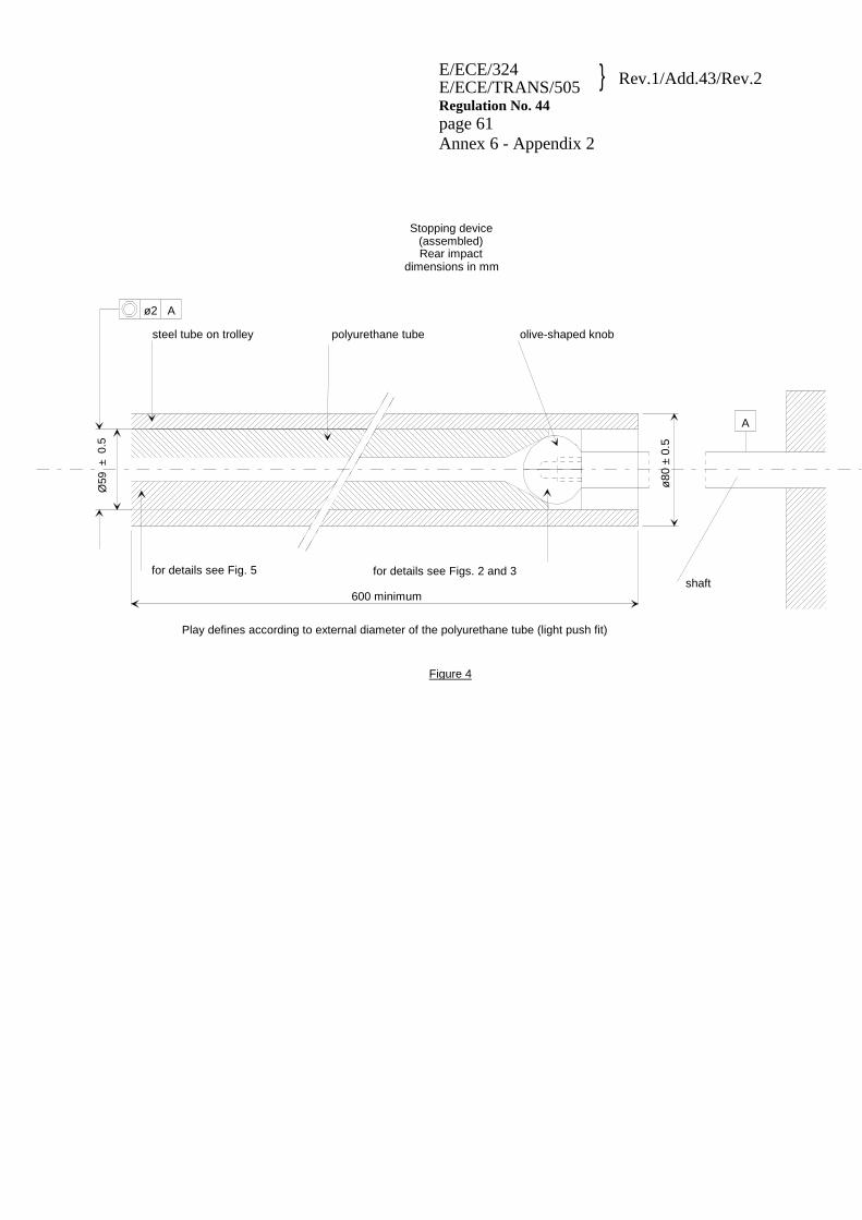
E/ECE/324 E/ECE/TRANS/505 } Rev.1/Add.43/Rev.2
Regulation No. 44 page 61 Annex 6 - Appendix 2
A
ø80
± 0
.5
polyurethane tube olive-shaped knobsteel tube on trolley
ø2 A
for details see Fig. 5 for details see Figs. 2 and 3
600 minimum
Play defines according to external diameter of the polyurethane tube (light push fit)
Figure 4
Stopping device(assembled)Rear impact
dimensions in mm
shaft
Ø59
± 0
.5

E/ECE/324 E/ECE/TRANS/505 } Rev.1/Add.43/Rev.2
Regulation No. 44 page 62 Annex 6 - Appendix 2
Figure 5
575 ± 2
Ø27
Ø35
Ø46
40
material A
Stopping devicepolyurethane tube
Rear impactdimensions in mm
+
0.5
Ø
59 +
0

Annex 6 - Appendix 3
ARRANGEMENT AND USE OF ANCHORAGES ON THE TEST TROLLEY 1. The anchorages shall be positioned as shown in the figure below. When attaching the standard anchorage plate to the anchorage points A and B or
B0 the plates shall be mounted with the bolt in the transverse horizontal direction with the angled surface facing inboard and shall be free to rotate about the axis
2. Child restraints in the "universal" and "restricted" categories shall use the
following anchorage points: 2.1. For child restraint using lap belts, points A and B; 2.2. For child restraint using lap and diagonal belts, points A, BO and C. 2.3. For child restraints using ISOFIX attachment, rearmost point H1 and H2. 3. Anchorages A, B and/or (rearmost) H1 H2 and D shall be used for child restraints
in the "semi-universal" category having only one additional upper anchorage. 4. Anchorages A, B and/or (rearmost) H1 H2, E and F shall be used for child
restraints in the "semi-universal" category having only one additional upper anchorages.
5. Anchorage points R1, R2, R3, R4 and R5 are the additional anchorage points for
rearward-facing child restraint systems in the "semi-universal" category having one or more additional anchorages (see paragraph 8.1.3.5.3.).
6. Except in the case of point C, (which represents the pillar loop position) the
points, which correspond to the arrangement of the anchorages show where the ends of the belt are to be connected to the trolley or to the load transducer, as the case may be. The structure carrying the anchorages shall be rigid. The upper anchorages must not be displaced by more than 0.2 mm in the longitudinal direction when a load of 980 N is applied to them in that direction. The trolley shall be so constructed that no permanent deformation shall occur in the parts bearing the anchorages during the test.
7. For carry-cots in group 0, the points A1 and/or B1 can be used alternatively, as
specified by the manufacturer of the restraint systems. A1 and B1 are located on a transverse line through R1 at a distance of 350 mm from R1.
8. For testing of child restraints in the "universal" and "restricted" categories, a
standard retractor belt, as specified in Annex 13, shall be fitted to the test seat.

Regulation No. FRENCH DRAFY
The webbing used between the retractor and the anchorage plate A1 of the standard safety belt shall be renewed for each dynamic test.
9. For testing of child restraints with top tether, the anchorage G1 or G2 shall be
used. 10. In the case of child restraints utilising a support leg, the Technical Service shall
select the anchorages to be used according to paragraphs 2., 3., 4. or 5. above and with the support leg adjusted as specified in paragraph 7.1.4.1.9.

Figure 1
625 200
60 20
80
80
475
D1
D2
150
150
350
350 300
125
200
200 525
925
125
ANG
C
F1
F2
D1
D2
E1
E2
Re
B1
B B0 R1
A A1
R3
R2
R4
R5
Cr
THE DISTANCE D1 AND D2 SHALL BE:
D1 = 325mm FOR VEHICLES WITH PARCEL SHELF (F1 D1 E1)
D1 = 1025mm FOR VEHICLES WITH FOLDING BACK REAR SEATS (ESTATE TYPE) (F2 D2 E2)
DIMENSIONS REFERRING TO Cr ARE TOLERANCED WITH: ± 2 mm EXCEPT FOR DISTANCE FLOOR TO Cr ±10mm
DISTANCE C - Re = 550mm ANGLE "ANG" = 30° MAXIMUM
1450
. G2
G1 .
550
DISTANCE C - Re = 530 mm
Re is located on the centerline of the retractor spool ANGLE "ANG" = 30° MAXIMUM
1450
G2’
G2
G2, G2’
550
G1
G1
.
.
.
.
.
X
DISTANCE C - Re = 530 mm
Re is located on the centerline of the retractor spool ANGLE "ANG" = 30° MAXIMUM

Regulation No. FRENCH DRAFY

Anchorage points H1 & H2 – 6 mm ± 0.1 mm
Figure 3

Regulation No. FRENCH DRAFY
Annex 7
CURVE OF TROLLEY'S DECELERATION OR ACCELERATION, AS FUNCTION OF TIME
In all cases the calibration and measuring procedures shall correspond to those defined in the International Standard ISO 6487:2002; the measuring equipment shall correspond to the specification of a data channel with a channel frequency class (CFC) 60.

Draft Reg. for iSize CRS Version 9 September 09
Step 1
Annex 7 - Appendix 1
CURVE OF TROLLEY'S DECELERATION OR ACCELERATION, AS FUNCTION OF TIME
FRONTAL IMPACT
Definition of the different curves
Time (ms) Acceleration (g)
Low corridor Acceleration (g) High corridor
0 - 10 20 0 - 50 20 28 65 20 - 80 - 28 100 0 - 120 - 0
The additional segment (see paragraph 7.1.4.1.1.3.2.) applies only for the acceleration sled

Annex 7 - Appendix 2
CURVES OF TROLLEY'S DECELERATION OR ACCELERATION, AS FUNCTION OF TIME
REAR IMPACT
Definition of the different curves
Time (ms) Acceleration (g)
Low corridor Acceleration (g) High corridor
0 - 21 10 0 10 7 - 20 14 - 37 14 - 52 7 - 52 0 70 - 21 70 - 0
The additional segment (see paragraph 7.1.4.1.1.3.2.) applies only for the acceleration sled

Annex 7 - Appendix 3
CURVE OF TROLLEY'S DECELERATION OR ACCELERATION, AS FUNCTION OF TIME
SIDE IMPACT
Definition of the different curves

Annex 8
DESCRIPTION OF MANIKINS
General 1.1. The manikins prescribed in this Regulation are described in this annex, in technical
drawing held by First Technology Safety Systems and in the user manuals delivered with the dummies.
1.2. Alternative manikins may be used provided that: 1.2.1. Their equivalence can be demonstrated to the satisfaction of the competent authority,
and 1.2.2. Their use is recorded in the test report, and in the communication form described in
Annex 1 to this Regulation. Description of the Manikins 1.The dimensions and masses of the manikins called Q0, Q1, Q1.5, Q3 and Q6 [and Q10]
described below are based on the anthropometry of 50th percentile children aged 0, 1, 1.5, 3 and 6 [and 10.5] years respectively.
1.2. The manikins consist of a metal and plastic skeleton covered with plastic skinned foam parts to complete body components.
1.3. For overview of the manikins, see below.

Q-dummy family from left to right: Q1.5, Q3, Q0, Q6 and Q1 [Q10 dummy, being under development, not yet shown]
2. Construction 2.1. Head
The head is largely made from synthetics. The head cavity is large enough to allow use of several instruments, including linear accelerometers and angular velocity sensors.
2.2. Neck
The neck is flexible and allows shear and bending in all directions. The segmented design allows a realistic rotational behavior. The neck is equipped with low stretch neck-cord in order to prevent excessive elongation. The neck-cord is also designed to act as a safety cord in case of rubber failure. A six channel load cell can be mounted at the neck-head and neck-torso interface. The Q0, Q1 and Q1.5 cannot accommodate the load cell between neck and torso
2.3. Thorax
The thorax of the child is represented by a single rib-cage. The deformation can be measured with a string potentiometer in Q1 and Q1.5 and an IR-TRACC sensors in Q3and Q6 [and Q10]. The shoulders are connected with a flexible joint to the thorax, allowing deformation forwards.
Accelerometers can be mounted on the spine to measure linear accelerations. The Q0 thorax has a simplified layout with an integral foam part for the complete torso.
2.4. Abdomen
The abdomen is foam covered with skin. Biomechanical data from children has been used to determine the required stiffness. The Q0 abdomen has has a simplified layout with an integral foam part for the complete torso.
2.5. Lumbar spine
The lumbar spine is a flexible rubber column, which allows shear and bending in all directions. A six channel load cell can be mounted between the lumbar spine and the pelvis, except for the Q0.
2.6. Pelvis
The pelvis is constructed from a iliac-sacrum bone part covered with a plastic flesh outer contour simulation. In the bone part removable hip joints are be inserted. An accelerometer array can be mounted in the pelvis. Special hip joints are available that allow to position the dummy in a standing position. The Q0 pelvis has a simplified layout with an integral foam part for the complete torso.
2.7. Legs
The legs are constructed with metal reinforced plastic bones cover with PVC skinned foam parts that represent the upper and lower flesh. The knee joints can be locked in any position. This feature can be used to facilitate positioning the dummy in a standing position. (Note that the dummy does not have the ability to stand without external support.) The Q0 legs have a simplified layout with one integral part per leg with a fixed angle at the knee.
2.8. Arms
The arms are constructed with plastic bones cover with PVC skinned foam parts that represent the upper and lower flesh. The elbow joints can be locked in any position. The Q0 arms have a simplified layout with one integral part per leg with a fixed angle at the knee.
3. Main characteristics 3.1. Mass

Table 1:Q-dummy manikin mass distributions
Q0 Q1 Q1.5 Q3 Q6 [Q10]
(design targets)
Mass in [kg]
Head + Neck (incl. acc. mount)
1.10±0.10 2.41±0.10 2.80±0.10 3.17±0.10 3.94±0.10 [4.19]
Torso (incl. acc. mount and chest deflection sensor)
1.50±0.15 4.21±0.25 4.74±0.25 6.00±0.30 9.07±0.40 [14.85]
(incl. suit)
Legs (together) 0.58±0.06 1.82±0.10 3.06±0.10 3.54±0.10 6.90±0.10 [12.50]
Arms (together) 0.28±0.03 0.89±0.10 1.20±0.10 1.48±0.10 2.49±0.10 [4.00]
Suit 0.27±0.05 0.27±0.05 0.30±0.05 0.40±0.10 0.55±0.10 (see torso)
Total 3.46±0.34 9.6±0.30 11.10±0.40 14.60±0.40 22.90±0.40 [35.50]
3.2. Principal dimensions Table 2:Q-dummy manikin dimensions
Q0 Q1 Q1.5 Q3 Q6 [Q10]
(design targets)
Dimensions in [mm]
Seating height (head tilted forward)
355 479 499 544 601 < 748
Shoulder height (sitting)
225 298 309 329 362 473
Stature (head tilted forward)
- 740 800 985 1143 < 1443
Chest depth - 114 113 146 141 171
Shoulder width 230 227 227 259 305 338
Hip width - 191 194 200 223 270
Back of buttocks to front of knees
130 211 235 305 366 488
Back of buttocks to popliteus
- 161 185 253 299 418

OLD TEXT (based on Annex 8 Appendix 1) TO BE RECONSIDERED
4. Adjustment of joints 4.1. General 4.1.1. In order to achieve reproducible results using the manikins, it is essential to specify
and adjust the friction in the various joints, the tension in the neck and lumbar cables, and the stiffness of the abdominal insert.
4.2. Adjustment of the neck cable 4.2.1. Place the torso on its back in a horizontal plane. 4.2.2. Mount the complete neck assembly without the head. 4.2.3. Tighten the tensioner nut on the Atlas-Axis block. 4.2.4. Place a suitable bar or bolt through the Atlas-Axis block. 4.2.5. Loosen the tensioner nut until the Atlas-Axis block is lowered by 10 ± 1 mm when a
load of 50 N directed downwards is applied to the bar or bolt through the Atlas-Axis block (see Figure 2).
4.3. Atlas-Axis joint 4.3.1. Place the torso on its back in a horizontal plane. 4.3.2. Mount the complete neck and head assembly. 4.3.3. Tighten the bolt and adjustment nut through the head and the Atlas-Axis block with
the head in a horizontal position. 50 N Figure 2
4.3.4. Loosen the adjustment nut until the head starts moving (see Figure 3). 4.4. Hip joint 4.4.1. Place the pelvis on its front in a horizontal plane. 4.4.2. Mount the upper leg without the lower leg. 4.4.3. Tighten the adjustment nut with the upper leg in a horizontal position. 4.4.4. Loosen the adjustment nut until the upper leg starts moving. 4.4.5. The hip joint should be checked frequently in the initial stages because of "running-
in" problems (see Figure 4). Figure 3 Figure 4
4.5. Knee joint 4.5.1. Place the upper leg in a horizontal position. 4.5.2. Mount the lower leg. 4.5.3. Tighten the adjustment nut of the knee joint with the lower leg in a horizontal
position. 4.5.4. Loosen the adjustment nut until the lower leg starts moving (see Figure 5). 4.6. Shoulder joint 4.6.1. Place the torso upright. 4.6.2. Mount the upper arm without the lower arm. 4.6.3. Tighten the adjustment nuts of the shoulder with the upper arm in a horizontal
position. Figure 5
4.6.4. Loosen the adjustment nuts until the upper arm starts moving (see Figure 6).
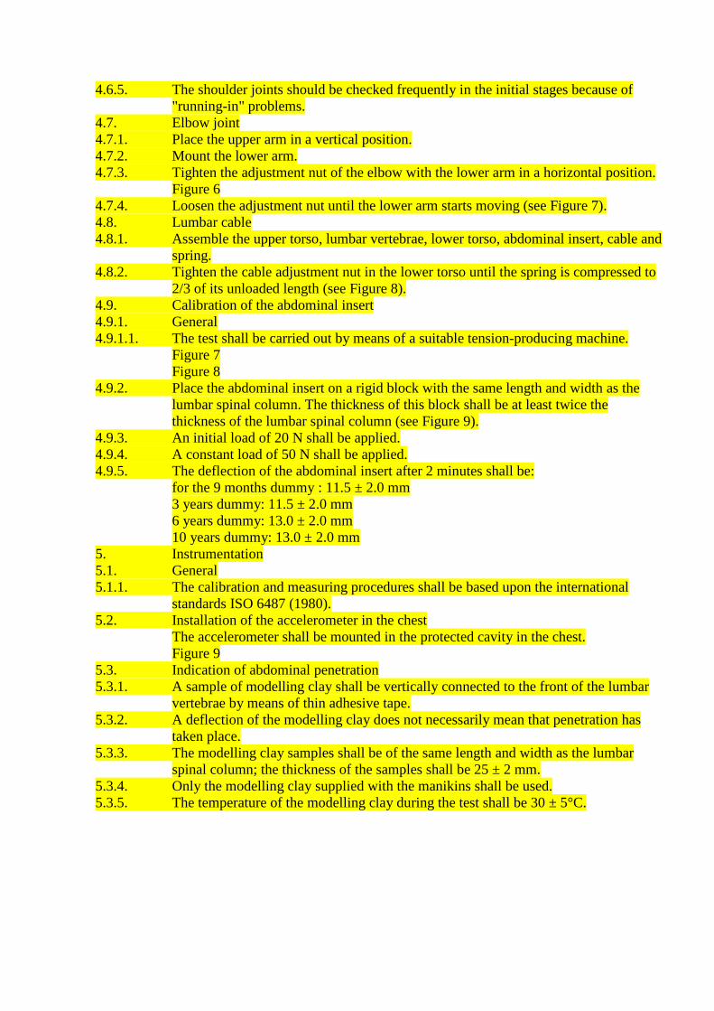
4.6.5. The shoulder joints should be checked frequently in the initial stages because of "running-in" problems.
4.7. Elbow joint 4.7.1. Place the upper arm in a vertical position. 4.7.2. Mount the lower arm. 4.7.3. Tighten the adjustment nut of the elbow with the lower arm in a horizontal position.
Figure 6 4.7.4. Loosen the adjustment nut until the lower arm starts moving (see Figure 7). 4.8. Lumbar cable 4.8.1. Assemble the upper torso, lumbar vertebrae, lower torso, abdominal insert, cable and
spring. 4.8.2. Tighten the cable adjustment nut in the lower torso until the spring is compressed to
2/3 of its unloaded length (see Figure 8). 4.9. Calibration of the abdominal insert 4.9.1. General 4.9.1.1. The test shall be carried out by means of a suitable tension-producing machine.
Figure 7 Figure 8
4.9.2. Place the abdominal insert on a rigid block with the same length and width as the lumbar spinal column. The thickness of this block shall be at least twice the thickness of the lumbar spinal column (see Figure 9).
4.9.3. An initial load of 20 N shall be applied. 4.9.4. A constant load of 50 N shall be applied. 4.9.5. The deflection of the abdominal insert after 2 minutes shall be:
for the 9 months dummy : 11.5 ± 2.0 mm 3 years dummy: 11.5 ± 2.0 mm 6 years dummy: 13.0 ± 2.0 mm 10 years dummy: 13.0 ± 2.0 mm
5. Instrumentation 5.1. General 5.1.1. The calibration and measuring procedures shall be based upon the international
standards ISO 6487 (1980). 5.2. Installation of the accelerometer in the chest
The accelerometer shall be mounted in the protected cavity in the chest. Figure 9
5.3. Indication of abdominal penetration 5.3.1. A sample of modelling clay shall be vertically connected to the front of the lumbar
vertebrae by means of thin adhesive tape. 5.3.2. A deflection of the modelling clay does not necessarily mean that penetration has
taken place. 5.3.3. The modelling clay samples shall be of the same length and width as the lumbar
spinal column; the thickness of the samples shall be 25 ± 2 mm. 5.3.4. Only the modelling clay supplied with the manikins shall be used. 5.3.5. The temperature of the modelling clay during the test shall be 30 ± 5°C.

Annex 9
Annex 10
Annex 11
Annex 12
Annex 13
Annex 14
Annex 15
Annex 16

Annex 17
TEST OF ENERGY ABSORBING MATERIAL 1. Headform 1.1. The headform shall consist of a solid wooden hemisphere with an added smaller
spherical segment as shown in Figure A below. It shall be constructed so that it can be dropped freely along the axis marked and it shall have provision for mounting an accelerometer in order to measure the acceleration along the direction of fall.
1.2. The headform shall have a total mass, including the accelerometer of
2.75 ± 0.05 kg. Dimensions in mm
Dimensions in mm
Figure A: Headform 2. Instrumentation The acceleration shall be recorded during the test, using equipment in accordance
with channel frequency class 1000 as specified in the latest version of ISO 6487. 3. Procedure
R64
R19
51
dire
ctio
n of
fall

3.1. The test shall be conducted on a completely assembled child restraint with a minimum of modification only where necessary to ensure access for the support (directly beneath the point of impact) and for the impactor device and such that there is minimal effect on the performance by the modification.
3.2. The assembled child restraint shall be fully supported on its outer surface in the
region of impact and be supported directly beneath the point of impact on a smooth rigid base, for example a solid concrete plinth.
3.3. Raise the headform to a height of 100 –0/+5 mm from the respective upper
surfaces of the assembled child restraint to the lowest point on the headform, and allow it to fall. Record the acceleration experienced by the headform during impact.
Annex 18
METHOD OF DEFINING HEAD IMPACT AREA OF DEVICES WITH BACKRESTS AND FOR REARWARD-FACING DEVICES DEFINING
THE MINIMUM SIZE OF SIDE WINGS 1. Place the device on the test seat described in Annex 6. Reclinable devices shall
be set in the most upright position. Place the smallest manikin in the device in accordance with the manufacturer's instructions. Mark a point "A" on the backrest on the same horizontal level as the shoulder of the smallest manikin at a point 2 cm inside the outer edge of the arm. All internal surfaces above the horizontal plane passing through point A shall comprise special energy-absorbing material tested in accordance with Annex 17. This material shall cover the internal surfaces of the backrest and side wings, including the inner edges (zone of radius) of the side wings. The energy absorbing material may be an integral part of the child seat. In the case of carry cot devices where a symmetrical installation of the dummy is not possible according to the device and manufacturer instructions, the lower limit of area at which material complying with Annex 17 shall be used, shall be all areas beyond dummy's shoulder in the head direction, when measured with this dummy in the carry cot in its worst position consistent with the manufactures instructions and the carry cot positioned on the test bench.
If a symmetrical installation of the dummy in the carry-cot may be possible, the
whole inner surfaces shall be covered with material complying with Annex 17; this material has to fulfill its purpose together with the inner side structure; the Technical Service may assess this aspect with further tests.
2. For rearward-facing devices there shall be side wings with a depth of minimum
90 mm measured from the median of the surface of the backrest. These side wings shall start at the horizontal plane passing through point "A" and continue to the top of the seat back. Starting from a point 90 mm below the top of the seat back, the depth of the side wing may be gradually reduced.
3. The requirement in paragraph 2. above for a minimum size of side wings does not
apply to child restraints of mass groups II and III in the specific vehicle category to be used in the luggage area according to paragraph 6.1.2. of this Regulation.