Embed Size (px)
Citation preview

AH
ME
DA
BA
DN
WE
S
Pro
jec
t Site

Report No.:1603-EI324-06-Vatva
0
FINAL REPORT
GEOTECHNICAL/SUB-SOIL INVESTIGATION WORK
FOR A BUILDING IN SURVEY NO.: 1212, FP NO. : 52, TP NO. : 84 OF VATVA
IN TAL.: CITY , DIST. : AHMEDABAD , STATE:GUJARAT
REPORT NO. : 1603/EI324/06/VATVA
MONTH & YEAR : FEBRUARY, 2016
SUBMITTED TO,
SHRI VIPULBHAI CHARODIA,
AHMEDABAD.
PREPARED BY
N.G. PATEL SOIL TESTING & F.M.PATWA MATERIAL TESTING LABORATORY
THE GUJARAT INSTITUTE OF CIVIL ENGINEERS AND ARCHITECTS, N.G.PATEL SOIL TESTING LABORATORY,
NIRMAN BHAVAN,LAW GARDEN ROAD, ELLISBRIDGE, AHMEDABAD
Phone No. : 079-26565935,65129967 Email .: [email protected]
NITESH SHAH K.C.PATEL PRESIDENT HON.SECRETARY PRASHANT SHAH SUDHIR BROKER BHADRESH SHAH P.B. PATHAK CHAIRMAN CO-CHAIRMAN CONVENER CO-ORDINATOR
LABORATORY COMMITTEE

Report No.:1603-EI324-06-Vatva
1
Date:22/03/2016 To, Shri Vipulbhai Charodia, Ahmedabad, Sub.: Report for the soil investigation work for a building at Vatva. We have conducted the soil investigation work at above mentioned site .Alongwith this letter we are submitting the soil report for the same alongwith the SBC analysis. Please call us for further information and clarification. Thanking You, For, GICEA N.G.Patel Soil Testing Laboratory, Authorised Signatory, Encl. 1.Two copy of Report 2.One report in soft copy
Report No.:1603-EI324-06-Vatva
2
CONTENTS
SS RR .. NN OO ..
CC HH AA PP TT EE RR
PP AA GG EE NN OO ..
1. Introduction. 3
2. Field Work. 3-4
3. Laboratory Work. 5
4. Physical Propert ies. 5-6
5. Shear Properties. 6-7
6. Soil Strat ification 7
7. Ground Water Table. 7
8. Conclusion And Recommendations 8
9. Appendix
1)Analysis of Allowable safe bearing Capacity
2) Table Showing Allowable safe bearing Capacity
3) Abbrevations and IS classif icat ions
4) Cross Sectional; Details Of Boreholes
5) Laboratory Test Tables
6) Location Plan
9- 10
11
12-14
15
16-29
30
Report No.:1603-EI324-06-Vatva
3
[ 1 ] INTRODUCTION : Shri Vipulbhai Charodia,Ahmedabad proposes geotechnical investigation work for a
building inVatva, Tal.: City, Dist : Ahmedabad in Gujarat state.
The purpose of the investigations was to determine the sub soil stratification of the soil,
geotechnical information & safe bearing capacity of the soil, so as to provide information that will
assist the structural engineers in the design of the foundations and the relevant works.
The Job was carried out under the guidance and supervision of the soil personnels of
G.I.C.E.A Laboratory,Ahmedabad, and client’s engineer.
[ 2 ] FIELD WORK : 1) Drilling two nos. of 150 mm dia borehole with casing whenever required up to maximum depth of 12.0 m from ground level. 2) Carryout standard penetration test at regular interval alternate to undisturb sampling 3) Collecting disturbed soil samples at regular interval as per the stratification of soil ,recording depth at which soil changes. 4) Collecting undisturbed samples (UDS) at regular interval alternate to SP Test or continuous UD samples at regular interval if subsoil is cohesive. [2.1] Borehole Drilling :
Drilling of 150 mm dia borehole was carried out by shell and Auger drilling method above
water table.Water was added while drilling but stopped at enough height above the test level to avoid
disturbance. Drilling below water table was made by percussion drilling method.casing is
required to be lowered if holes do not retain its shape.Care is taken to maintain ground water table
during drilling and particularly before testing or sampling levels.In no case casing is allowed to
advance below the bottom of borehole. Chiselling is carried out if required while drilling.The
Location of borehole was decided with due consideration of Client/Consultant of the project.

Report No.:1603-EI324-06-Vatva
4
(2.2) Collection of Samples:
Undisturbed soil samples in 38mm Ø shelby tubes were collected in the thin walled sampling
tubes in accordance with IS:2132-1981at regular interval for finding shear parameters, field density,
moisture content etc. of soil.The sampling tube was connected to the rod by jarring link in case of
38mm Ø tubes.’A’ drill rods were connected by suitable adaptor with ball check value. Before
lowering the sampler ,the borehole was cleaned properly and sampling tubes were lightly oiled from
inner and outer side.
Sampling tube was pushed into the borehole by pressure hammering as per the soil stiffness.
The sampling tubes were waxed immediately after removal.
In case of medium to coarse grained ,non-cohesive sand samples,where sampling is
unsuccessful,Standard Penetration Tests was carried out after cleaning the borehole.
However, disturbed soil samples from shell or split spoon samplers were also collected in
polythene bags with proper levels during drilling for finding index properties of the soil.
[ 2.3 ] Standard Penetration Test :
The standard penetration tests were performed in accordance with IS:2131:1981 using the
standard split spoon sampler & 63.5Kg hammer at the desired intervals. Before testing ,the borehole
was cleaned properly and Split spoon sampler was centrally seated in the borehole.In case of SPT to
be conducted below water table,care was taken to keep casing position above the borehole
depth..The water level in borehole is maintained above or at least at the water table.
A standard hammer of 63.5 kg is dropped from a height of 75 cms. And the no. of
blows for penetration of sampler for 0-15,15-30 and 30-45 cms were noted in table no.3.
Standard penetration test value Ns is considered for last 30 cm penetration,For non plastic silts
and fine sands Ns value is corrected for effective overburden pressure and dilatancy.Correction is
applied for tests conducted below water table.
Report No.:1603-EI324-06-Vatva
5
[ 3 ] LABORATORY WORK
Following laboratory tests were carried out on the samples collected from the site.
1. Water content on selected samples from SPT
2. Field density,Moisture content and dry density of undisturbed samples.
3. Grain size Analysis of SPT samples,.UD samples and disturbed samples
covering each soil strata.
4. Atterberg’s Limit for samples
5. Specific gravity Test for samples as per 3.
6. Shrinkage Limit / Free Swell / Differential Swell test for selected samples of
expansive soil
7. Test for shear properties of selected samples.
8. Unconfined compressive Strength on saturated cohesive soil
9. Triaxial Shear test under UU/CU condition with or without pore pressure measurement as
per in situ conditions.Normally soft cohesive saturated samples will be consolidated at average
overburden pressure.
The common practice adopted in the field and laboratory testing by & large are as per I S
code indicated . Results of the laboratory tests performed on various soil samples are presented in the
form of table at the end of report.
[ 4 .0] PHYSICAL PROPERTIES:- The moisture cans collected from SPT samplers from the field are weighed and placed in
oven for drying to determine natural moisture content(NMC). Results are tabulated in table-3
UDS are extracted using screw type extractor and samples were prepared as per the
required size of the test. Weight and volume of the samples were noted before extracting from
tubes.Average bulk density is calculated and samples were placed in oven to get the field moisture
content for computing the dry density.Results are tabulated in table 4.

Report No.:1603-EI324-06-Vatva
6
Specific gravity with specific gravity bottle/pycnometer is calculated as per IS
2720.Results were tabulated in table4.Saturation of sample in % is also calculated which is a
useful data for deciding the condition of triaxial shear test.
Grain size analysis is made by IS sieves of sizes 4.75mm,2.00mm,1.00mm,0.425mm,0.25mmand
0.075mm.For coarse grained soil a graph of partical size v/s cumulative % finer is plotted.
For fine grained soil wet analysis is made on plummet balance.Results are tabulated in table 5
Liquid limit and Plastic Limit tests are carried out with distilled water as per IS 2720
part – 5.The samples are tested at a minimum of 24 hours after the addition of water. Liquid limit
is done on casagrande standards with occasional checking by Cone penetration method.
The soil samples showing high plasticity were checked for swelling and shrinkage.
Firstly for rough estimate,free swell test is carried out as per IS 2720 part – 40.Shrinkage limit test is
carried out as per is 2720 part 6.
[5.0] SHEAR PROPERTIES:-
Shear tests were carried out by three methods.
1) Unconfined compressive strength as per IS 2720 part-10 for the saturated plastic soil
2) Triaxial shear test is tobe carried out on samples of size 38mm dia and 76 mm in height
on motorized 30 speed load frame .The confining pressure б3 is applied to the cell by oil
water constant pressure system. The tests are carried out for the three conditions
a) Unconsolidated Undrained (UU) test without pore water pressure measurement as per
IS 2720 part 1
b) Consolidated Undrained (CU) test without pore water pressure measurement as per
IS 2720 part 11
The condition decided on type of sample and water table condition or designers
specifications.
c) Direct/box shear test on noncohesive medium to coarse sandy soil as per IS 2720 part
13. The graph for triaxial shear test is plotted by modified method .
Report No.:1603-EI324-06-Vatva
7
[ 6 .0] SOIL STRATIFICATIONS.: [ 6.1 ] BOREHOLE: BH-1 (6.1.1) Layer No. 1 This layer from 0.0 m to 12.0 m depth (thickness is 12.00 m) is observed to consist of
Blackish to yellowish brown colored silty sand. The grain size analysis and consistency limits
indicate the layer as SM/SW-SM. The grain size analysis shows variation in % of silt and clay is
from 13 to 47 % ; in sand is from 53 to 86 % and gravels varies from 00 to 03 %. The soil is non
plastic.
[ 6.2 ] BOREHOLE: BH-2 (6.2.1) Layer No. 1 This layer from 0.0 m to 12.0 m depth (thickness is 12.00 m) is observed to consist of
Blackish to yellowish brown colored silty sand. The grain size analysis and consistency limits
indicate the layer as SM/SW-SM. The grain size analysis shows variation in % of silt and clay is
from 12 to 38 % ; in sand is from 51 to 87 % and gravels varies from 00 to 08 %. The soil is non
plastic.
[ 7 ] GROUND WATER TABLE :
Ground water level was not observed in any of the borehole up to 12.00 m depth below GL at
the time of investigation. (March 2016).

Report No.:1603-EI324-06-Vatva
8
8 ] CONCLUSIONS & RECOMMENDATION: (8.1) The site for proposed soil investigation work at Vatva in general is observed to consist of silty
sand up to 12.00 m depth of termination.
Ground water table was not encountered in any of the borehole up to 12.00 m depth below GL
at the time of investigation. (March, 2016)
(8.2) The net safe bearing capacity of open foundation having width varying from 1.5 to 2.0 m at 3.00
m to 4.50 m depth below GL is recommended in following paras considering 50 mm maximum
permissible settlement and in natural condition of soil. For indivisual depth and size of footing please
refer table on page no.11 of this report.
( 8.3) The top soil is not having swelling potential and hence is suitable to be used for back /
Plinth filling purpose.
( 8.4) The results of the laboratory tests are incorporated in the form of table at the later part of the
report.
For,,G.I.C.E.A.,
N.G.PATEL SOIL TESTING LABORATORY ,
Authorised Signatory

Report No.:1603-EI324-06-Vatva
9
APPENDIX Calculation for Allowable Bearing Capacity Design Data : Foundation Type : Square Footing Width of Footing : 1.50 m Depth of Footing : 1.50 m below basement level ( 3.5 m below EGL) Failure Mode : Mixed Shear Failure Shape and Depth Factors : Not considered Water Table : not met with Factor of Safety : 3.00 Permissible Settlement : 50.00 mm Soil From To C Ø N'' γb Strata (m) (m) (Kg/cm²) (deg) (g/cc) Silty sand 0.00 12.00 - 30.0 - 1.64 Soil Strata:
Calculations : Ultimate Bearing Capacity (for Mixed Shear Failure) q'd = 0.92 c N'c + q (N'q - 1) + ½ B γ N'γ = 0.92 × 0 × 26.61 + 0.246 × (15.61 - 1) + 0.5 × 150 × 0.00164 × 18.42 = 0 + 3.594 + 2.266 = 5.86 Kg/cm²

Report No.:1603-EI324-06-Vatva
10
= 58.6 T/m² Where c = Cohesion = 0 kgf/cm² q = Effective surcharge at base of fdn = 0.246 kgf/cm² B = Width of footing = 150 cm γ = Bulk unit weight of foundation soil = 0.00164 Kgf/cm³ W' = Correction factor for location of water table = 1 Ø = Angle of shearing resistance of soil in degrees = 30 N'c = Bearing Capacity Factor = 26.61 N'q = Bearing Capacity Factor = 15.61 N'γ = Bearing Capacity Factor = 18.42 Safe Bearing Capacity = 19.53 T/m² [Considering a Safety Factor of 3] Settlement Calculation Settlement in Non-Cohesive Layer from 0 to 12 m (S1) [from graph - Fig 9 (IS 8009 Part 1 - 1976)], for Width 'B' = 1.5 m and N = 31, Settlement = 7.18 mm (per Kg/cm² of Pressure) x 1.95 Kg/cm² (Foundation Pressure) = 14.01 mm Total Settlement Sf = S1 = 14.01 = 14.01 mm Allowable Bearing Capacity = 19.5 T/m² for width of foundation 1.5 mts and Settlement of 14 mm For,,G.I.C.E.A., N.G.PATEL SOIL TESTING LABORATORY
Authorised Signatory

Report No.:1603-EI324-06-Vatva
11
RECOMMENDED ALLOWABLE NET SAFE BEARING CAPACITY
Sl
Width Depth Surcharge W' qsafe Settlement Remarks
No
(m) (m) Kgf/cm³ T/m² (mm)
1
1.50 3.50 0.25 1.00 19.5 14.0
2
1.50 4.00 0.33 1.00 23.5 16.9
3
1.50 4.50 0.41 1.00 27.5 19.8
4
1.50 5.00 0.49 1.00 31.5 22.6
5
2.00 3.50 0.25 1.00 22.1 17.2
6
2.00 4.00 0.33 1.00 26.0 20.3
7
2.00 4.50 0.41 1.00 30.0 23.5
8
2.00 5.00 0.49 1.00 34.0 26.6
For,,G.I.C.E.A., N.G.PATEL SOIL TESTING LABORATORY,
Authorised Signatory

Report No.:1603-EI324-06-Vatva
12
IS CLASSIFICATIONS:
GW:Well graded gravels,gravel sand mixture or no fines GP : Poorly graded gravels or gravels sand mixture,little or no fines GM: Silty gravels,poorly graded gravel-sand-silt mixtures GC : Clayey gravels,poorly graded gravels-sand-clay mixtures SW : Well graded sands,gravelly sands ,little or no fines SP : Poorly graded sands or gravelly sands;little or no fines SC : Claye sands,poorly graded sand-clay mixture SM: Silty sands, poorly graded sand-silt mixture ML: Inorganic silt and very fine sands,silty or clayey fine sands or clayey silt with non to low plasticity CL: Inorganic clays,gravelly clays,sandy clays,silty clays,lean clays of low plasticity OL: Organic silts and organic silty clay of low plasticity MI: Inorganic silts, silty or clayey fine sands or clayey silts of medium plasticity CI: Inorganic clays,gravely clays,sandy clays,silty clays,lean clays of medium plasticity OI : Organic silts and silty clay of medium plasticity MH: Inorganic silt of high compressibility,micaceous or diatomaceous fine sandy or silty soils,elastic silts CH: Inorganic clays of high plasticity,fat clays OH: Organic clays of medium to high plasticity Pt.: Peat and other highly organic soil with very high compressibility

Report No.:1603-EI324-06-Vatva
13
ABBREVIATIONS
DS : Disturbed Soil Sample
UDS : Undisturbed Soil Sample
SPT : Standard Penetration Test
SBC : Safe Bearing Capacity
NP : Non Plastic
DST : Direct Shear Test
LL : Liquid Limit
PL : Plastic Limits
PI : Plasticity Index
* : Remolded Sample
Ref. : Refusal

Report No.:1603-EI324-06-Vatva
14
GENERAL TERMS AND CONDITIONS
1. The test are carried out under certain laboratory condition and parameter 2. Results given in this report refers only to the material supplied to the laboratory.
3. The test report do not indicate the quality of the product or usage of product or suitability of the product or material. 4. This test report does not indicate the sampling criterion for testing the samples.. 5. Any site testing or supervision is to be done separately. 6. Any kind of addition ,alteration or deletion is not permitted. 7. Reproduction of this reppport in whole or in part by any means except with written permission of the testing agency shall be deemed to be an infringement. 8 . The report/results are not to be used for publicity. For, G.I.C.E.A.,
N.G.PATEL SOIL TESTING LABORATORY
Authorised Signatory

Bore Hole : 1
SM
0.00 (8.00%)
-1.50 N=14 (10.00%)
-3.00 1.65 (3.00%) 1.60Cuu=0.1, Øuu=27.7°
-4.50 N=30 (4.00%)
-6.00 1.50 (1.00%) 1.48
-7.50 N=40 (6.00%)
-9.00 1.89 (3.00%) 1.84
-10.50 N=49 (6.00%)
-12.00 1.92 (3.00%) 1.86
Bore Hole : 2
SM-SW
0.00 (6.00%)
-1.50 1.64 (6.00%) 1.55
-3.00 N=23 (3.00%)
-4.50 1.58 (3.00%) 1.53Cuu=0.1, Øuu=29.7°
-6.00 N=31 (3.00%)
-7.50 1.58 (3.00%) 1.54
-9.00 N=41 (6.00%)
-10.50 1.73 (3.00%) 1.67
-12.00 N=54 (7.00%)
BORE-LOG SECTION FOR PROJECT : EI324 Vatva
Note:(1) Figures on the Left Side shows R.L. and Type of Sample (D - DS, U - UDS, S - SPT, C - Core, V - Field Vane Shear)(2) Figures on the Right Side shows : (a) for SPT Samples : Nc - No. of Blows/300 mm Penetration (N.M.C.)
(b) for UDS Samples : Bulk Density, (N.M.C), Dry Density
{15}
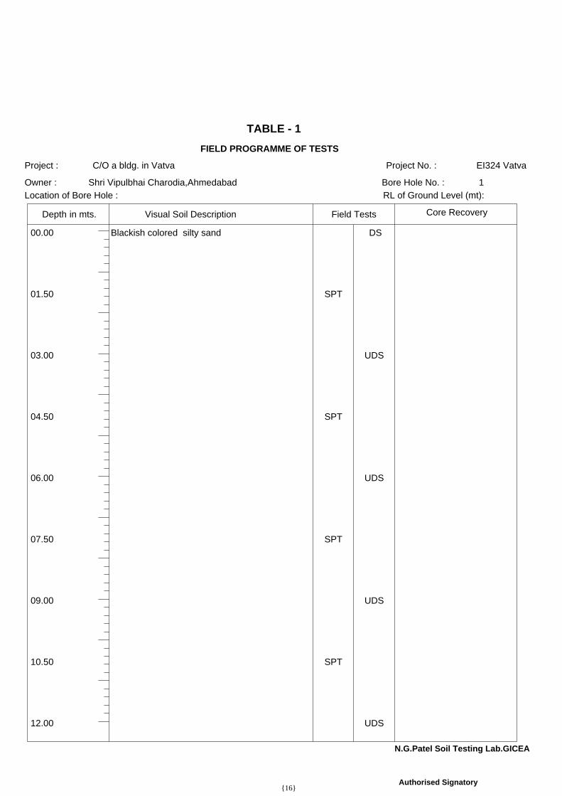
00.00 Blackish colored silty sand DS
01.50 SPT
03.00 UDS
04.50 SPT
06.00 UDS
07.50 SPT
09.00 UDS
10.50 SPT
12.00 UDS
TABLE - 1FIELD PROGRAMME OF TESTS
EI324 VatvaC/O a bldg. in Vatva
Shri Vipulbhai Charodia,Ahmedabad 1
Depth
Project : Project No. :
Owner : Bore Hole No. :Location of Bore Hole : RL of Ground Level (mt):
in mts. Visual Soil Description Field Tests Core Recovery
N.G.Patel Soil Testing Lab.GICEA
Authorised Signatory{16}

0.00 8.40
1.50 03 06 08 14 20 10.19
3.00 3.40
4.50 06 12 18 30 31 3.63
6.00 1.23
7.50 09 16 24 40 35 6.38
9.00 2.73
10.50 11 21 28 49 37 5.63
12.00 3.46
TABLE - 2RESULTS OF STANDARD PENETRATION TEST
EI324 VatvaC/O a bldg. in VatvaShri Vipulbhai Charodia,Ahmedabad 1
Depth0 - 150 mm 150 - 300 mm 300 - 450 mm /300 mm) value of Ns) (in %)
N.G.Patel Soil Testing Lab.,GICEA
Authorised Signatory
Project : Project No. :Owner : Bore Hole No. :
No. of Blows for Penetration Ns (Blows Nc(Corrected N. M. C.in mts.
{17}

0.00 8.40
1.50 10.19
3.00 3.401.65 1.60 2.49 0.15
4.50 3.63
6.00 1.231.50 1.48 2.46 0.05
7.50 6.38
9.00 2.731.89 1.84
10.50 5.63
12.00 3.461.92 1.86
TABLE - 4INSITU DENSITY, MOISTURE CONTENT, DRY DENSITY & SPECIFIC GRAVITY
EI324 VatvaC/O a bldg. in VatvaShri Vipulbhai Charodia,Ahmedabad 1
Depth
Project : Project No. :Owner : Bore Hole No. :
Bulk Density Natural Moisture Dry Density Specific SaturationSample (mts.) in gms/cc Content (%) in gms/cc Gravity
For,GICEA,N.G.Patel Soil Testing Laboratory
Authorised Signatory{18}

0.00 0.00 to 12.00/D 0 0 4 49 47
1.50 0.00 to 12.00/S 0 0 2 54 44
3.00 0.00 to 12.00/U 2 2 2 65 29
4.50 0.00 to 12.00/S 2 1 13 71 13
6.00 0.00 to 12.00/U 0 1 2 83 14
7.50 0.00 to 12.00/S 2 1 11 63 23
9.00 0.00 to 12.00/U 6 10 16 48 20
10.50 0.00 to 12.00/S 3 4 10 50 33Clay Silt Fine
SandMedium Coarse Gravel
0.001 0.01 0.1 1 10PARTICLE SIZE (mm)
0.0
7.5
15.0
22.5
30.0
37.5
45.0
52.5
60.0
67.5
75.0
82.5
90.0
97.5
TABLE - 3PARTICLE SIZE DISTRIBUTION
EI324 VatvaC/O a bldg. in VatvaShri Vipulbhai Charodia,Ahmedabad 1
Depth
Project No. :Project :Owner : Bore Hole No. :
Gravel Sand in % Silt in %Type ofSample
Label Soil Strata Coarse Medium Finein % +(>4.75 mm) (4.75 - 2 mm) (2mm - 425µ) (425 - 75 µ) Clay in %
For,GICEA,N.G.Patel Soil Testing Laboratory
Authorised Signatory{19}

12.00 0.00 to 12.00/U 2 2 6 50 40Clay Silt Fine
SandMedium Coarse Gravel
0.001 0.01 0.1 1 10PARTICLE SIZE (mm)
0.0
7.5
15.0
22.5
30.0
37.5
45.0
52.5
60.0
67.5
75.0
82.5
90.0
97.5
TABLE - 3PARTICLE SIZE DISTRIBUTION
EI324 VatvaC/O a bldg. in VatvaShri Vipulbhai Charodia,Ahmedabad 1
Depth
Project No. :Project :Owner : Bore Hole No. :
Gravel Sand in % Silt in %Type ofSample
Label Soil Strata Coarse Medium Finein % +(>4.75 mm) (4.75 - 2 mm) (2mm - 425µ) (425 - 75 µ) Clay in %
For,GICEA,N.G.Patel Soil Testing Laboratory
Authorised Signatory{20}

3.00 0.06 27.70
Cuu Øuu
Undisturbed
Undisturbed
Undisturbed
0.50
1.00
1.50
0.28
0.67
0.80
0 1 2σn (in Kg/cm²)
0
1
TABLE - 4BOX SHEAR TEST
EI324 VatvaC/O a bldg. in Vatva
Shri Vipulbhai Charodia,Ahmedabad 1
Depth
Project : Project No. :Owner : Bore Hole No. :
Shear Values from GraphSample Type Normal Stress Shearing Stressσ τSample (UD/Rm) in Kg/cm² in Kg/cm² (Kg/cm²) (Kg/cm²)
BOX SHEAR GRAPH
N.G.Patel Soil Testing Lab.,GICEA
Authorised Signatory
{21}

00.00 Blackish colored silty sand DS 8.40 0 53 47 - -
SM
01.50 SPT 14 10.19 0 56 44 - -
03.00 UDS 3.40 1.65 1.60 2.49 2 69 29 - - Buu 0.06 27.7°
04.50 SPT30
3.63 2 85 13 - -
06.00 UDS 1.23 1.50 1.48 2.46 0 86 14 - -
07.50 SPT40
6.38 2 75 23 - -
09.00 UDS 2.73 1.89 1.84 6 74 20 - -
10.50 SPT49
5.63 3 64 33 - -
12.00 UDS 3.46 1.92 1.86 2 58 40 - -
SUMMARY OF GEOTECHNICAL EXPLORATIONSEI324 Vatva
1150 mmSHELL & AUGER
12-03-1622-03-16
Depth
Below Termination LevelWater Table
THE GUJARAT INSTITUTE OF CIVIL ENGINEERS & ARCHITECTS"Nirman Bhavan",Opp. Law Garden,Ellisbridge,Ahmedabad-380006
Project No. : Bore Hole Started on : Depth of :Bore Hole No. : Bore Hole Completed on : R. L. of Ground Level :Method of Drilling : Diameter of Bore Hole : Location of Bore Hole :
Field Test Particle Size AtterbergNs Rock Natural Density Spe- Shri- Free Shear PropertiesI. S. Additional/Samples Properties LimitsAnalysis(in gms/cc)No. of Moist. cific nkge swell C ØTestVisual Soil Descriptionin Classi- Tests orSPT UDS Blows per C.R. RQD Content Gra- Gr. Sn Silt+ LL PL PI Lim. Indx (Kg/ inTypemetres fication Bulk Dry Remarks% vityVST DS 300 mm % % % % Clay % % % % % cm²) Deg.
Standard Penetration Test PI - Plasticity Index Cv - Coeff. of Consolidation C.R. - Core RecoverySPT - DS - Disturbed Sample Gr - Gravel LL - Liquid LimitVST - Vane Shear Test Sn - Sand PL - Plastic Limit C, Ø - Shear Parameters Mv - Coeff. of Volume Change RQD - Rock Quality Designation
For, GICEA,N.G.Patel Soil Testing Laboratory
Authorised Signatory
{22}

00.00 Blackish colored silty sand DS
01.50 UDS
03.00 SPT
04.50 UDS
06.00 SPT
07.50 UDS
09.00 SPT
10.50 UDS
12.00 SPT
TABLE - 1FIELD PROGRAMME OF TESTS
EI324 VatvaC/O a bldg. in Vatva
Shri Vipulbhai Charodia,Ahmedabad 2
Depth
Project : Project No. :
Owner : Bore Hole No. :Location of Bore Hole : RL of Ground Level (mt):
in mts. Visual Soil Description Field Tests Core Recovery
N.G.Patel Soil Testing Lab.GICEA
Authorised Signatory{23}

0.00 6.38
1.50 5.82
3.00 06 09 14 23 27 3.45
4.50 3.26
6.00 08 12 19 31 29 3.09
7.50 2.88
9.00 12 18 23 41 33 5.63
10.50 3.46
12.00 14 24 30 54 38 6.98
TABLE - 2RESULTS OF STANDARD PENETRATION TEST
EI324 VatvaC/O a bldg. in VatvaShri Vipulbhai Charodia,Ahmedabad 2
Depth0 - 150 mm 150 - 300 mm 300 - 450 mm /300 mm) value of Ns) (in %)
N.G.Patel Soil Testing Lab.,GICEA
Authorised Signatory
Project : Project No. :Owner : Bore Hole No. :
No. of Blows for Penetration Ns (Blows Nc(Corrected N. M. C.in mts.
{24}

0.00 6.38
1.50 5.821.64 1.55 2.45 0.24
3.00 3.45
4.50 3.261.58 1.53 2.43 0.13
6.00 3.09
7.50 2.881.58 1.54
9.00 5.63
10.50 3.461.73 1.67
12.00 6.98
TABLE - 4INSITU DENSITY, MOISTURE CONTENT, DRY DENSITY & SPECIFIC GRAVITY
EI324 VatvaC/O a bldg. in VatvaShri Vipulbhai Charodia,Ahmedabad 2
Depth
Project : Project No. :Owner : Bore Hole No. :
Bulk Density Natural Moisture Dry Density Specific SaturationSample (mts.) in gms/cc Content (%) in gms/cc Gravity
For,GICEA,N.G.Patel Soil Testing Laboratory
Authorised Signatory{25}

0.00 0.00 to 12.00/D 0 0 10 52 38
1.50 0.00 to 12.00/U 8 5 6 40 41
3.00 0.00 to 12.00/S 1 1 20 66 12
4.50 0.00 to 12.00/U 0 1 3 64 32
6.00 0.00 to 12.00/S 0 1 3 82 14
7.50 0.00 to 12.00/U 0 1 9 56 34
9.00 0.00 to 12.00/S 5 6 15 50 24
10.50 0.00 to 12.00/U 3 4 10 50 33Clay Silt Fine
SandMedium Coarse Gravel
0.001 0.01 0.1 1 10PARTICLE SIZE (mm)
0.0
7.5
15.0
22.5
30.0
37.5
45.0
52.5
60.0
67.5
75.0
82.5
90.0
97.5
TABLE - 3PARTICLE SIZE DISTRIBUTION
EI324 VatvaC/O a bldg. in VatvaShri Vipulbhai Charodia,Ahmedabad 2
Depth
Project No. :Project :Owner : Bore Hole No. :
Gravel Sand in % Silt in %Type ofSample
Label Soil Strata Coarse Medium Finein % +(>4.75 mm) (4.75 - 2 mm) (2mm - 425µ) (425 - 75 µ) Clay in %
For,GICEA,N.G.Patel Soil Testing Laboratory
Authorised Signatory{26}

12.00 0.00 to 12.00/S 4 5 9 46 36Clay Silt Fine
SandMedium Coarse Gravel
0.001 0.01 0.1 1 10PARTICLE SIZE (mm)
0.0
7.5
15.0
22.5
30.0
37.5
45.0
52.5
60.0
67.5
75.0
82.5
90.0
97.5
TABLE - 3PARTICLE SIZE DISTRIBUTION
EI324 VatvaC/O a bldg. in VatvaShri Vipulbhai Charodia,Ahmedabad 2
Depth
Project No. :Project :Owner : Bore Hole No. :
Gravel Sand in % Silt in %Type ofSample
Label Soil Strata Coarse Medium Finein % +(>4.75 mm) (4.75 - 2 mm) (2mm - 425µ) (425 - 75 µ) Clay in %
For,GICEA,N.G.Patel Soil Testing Laboratory
Authorised Signatory{27}

4.50 0.05 29.68
Cuu Øuu
Undisturbed
Undisturbed
Undisturbed
0.50
1.00
1.50
0.31
0.68
0.88
0 1 2σn (in Kg/cm²)
0
1
TABLE - 4BOX SHEAR TEST
EI324 VatvaC/O a bldg. in Vatva
Shri Vipulbhai Charodia,Ahmedabad 2
Depth
Project : Project No. :Owner : Bore Hole No. :
Shear Values from GraphSample Type Normal Stress Shearing Stressσ τSample (UD/Rm) in Kg/cm² in Kg/cm² (Kg/cm²) (Kg/cm²)
BOX SHEAR GRAPH
N.G.Patel Soil Testing Lab.,GICEA
Authorised Signatory
{28}

00.00 Blackish colored silty sand DS 6.38 0 62 38 - -
SM-SW
01.50 UDS 5.82 1.64 1.55 2.45 8 51 41 - -
03.00 SPT 23 3.45 1 87 12 - -
04.50 UDS 3.26 1.58 1.53 2.43 0 68 32 - - Buu 0.05 29.7°
06.00 SPT31
3.09 0 86 14 - -
07.50 UDS 2.88 1.58 1.54 0 66 34 - -
09.00 SPT41
5.63 5 71 24 - -
10.50 UDS 3.46 1.73 1.67 3 64 33 - -
12.00 SPT54
6.98 4 60 36 - -
SUMMARY OF GEOTECHNICAL EXPLORATIONSEI324 Vatva
2150 mmSHELL & AUGER
12-03-1622-03-16
Depth
Below Termination LevelWater Table
THE GUJARAT INSTITUTE OF CIVIL ENGINEERS & ARCHITECTS"Nirman Bhavan",Opp. Law Garden,Ellisbridge,Ahmedabad-380006
Project No. : Bore Hole Started on : Depth of :Bore Hole No. : Bore Hole Completed on : R. L. of Ground Level :Method of Drilling : Diameter of Bore Hole : Location of Bore Hole :
Field Test Particle Size AtterbergNs Rock Natural Density Spe- Shri- Free Shear PropertiesI. S. Additional/Samples Properties LimitsAnalysis(in gms/cc)No. of Moist. cific nkge swell C ØTestVisual Soil Descriptionin Classi- Tests orSPT UDS Blows per C.R. RQD Content Gra- Gr. Sn Silt+ LL PL PI Lim. Indx (Kg/ inTypemetres fication Bulk Dry Remarks% vityVST DS 300 mm % % % % Clay % % % % % cm²) Deg.
Standard Penetration Test PI - Plasticity Index Cv - Coeff. of Consolidation C.R. - Core RecoverySPT - DS - Disturbed Sample Gr - Gravel LL - Liquid LimitVST - Vane Shear Test Sn - Sand PL - Plastic Limit C, Ø - Shear Parameters Mv - Coeff. of Volume Change RQD - Rock Quality Designation
For, GICEA,N.G.Patel Soil Testing Laboratory
Authorised Signatory
{29}

Sa
tej
Ho
me
s
Va
twa
Ma
nth
an
Sa
nik
Up
tya
ka
So
cie
ty
Ayo
dh
ya
Ap
pa
rtme
nt
Sa
ng
an
i'V
rajb
ho
om
iO
m S
ha
nti
Bu
ng
low
s
PR
OJ
EC
T S
ITE
N
WE
S
Ge
ratp
ur

VAL
VE &
PIPE
EXT
ERNA
L FIRE
HY
DR
ANT
VAL
VE &
PIPE
EXT
ERNA
L FI RE
HY
DR
ANT
VAL
VE &
PIPE
EXT
ERNA
L FI RE
HY
DR
ANT
7.57
3.056.01
7.57
6.32
3.00
3.05
3.05
7.62
7.62
7.62
7.62
6.32
7.62
7.626.32
5.09
5.08
4.03
4.04
4.03
4.03
4.05
4.05
3.00
7.57
7.57
7.57
7.62
7.623.05
6.01
RCC CHANNEL FOR DRAINAGE
DN
SLOPE :- 1:7 MT.(LENGTH = 32.27 MT.)
15.67
WITH SLOPE - 1:2
1.80 MT. WIDE PATHW
AY
RCC CHANNEL FOR DRAINAGE
RCC CHANNEL FOR DRAINAGE
RCC CHANNEL FOR DRAINAGE
WITH SLOPE - 1:2
1.80 MT. WIDE PATHW
AY
RCC CHANNEL FOR DRAINAGE
RCC CHANNEL FOR DRAINAGE RCC CHANNEL FOR DRAINAGE
6.10 MT. WIDE RAMP DN TO BASEMENT
44.19
18.99
28.10
32.61
56.92
BLO
CK
: A
1321.99
B.U
P AR
EA TABLEFLO
OR
GR
. FLOO
R
IN SQ.M
T.B
LOC
K : B
+CB
LOC
K : D
TOTA
L
2530.311st. FLO
OR
2454.692nd. FLO
OR
2454.693rd. FLO
OR
2454.694th. FLO
OR
2454.695th. FLO
OR
2454.696th. FLO
OR
2454.69------
7th. FLOO
R645.41
487.291132.70
9584.54T
OT
AL
5368.674027.96
26409.15
BLO
CK
: A1168.94
FLOO
RB
LOC
K : B
+CB
LOC
K : D
TOTA
L
1137.04553.08
428.771137.04
553.08428.77
1144.82553.08
428.771144.82
553.08428.77
1137.04553.08
428.771137.04
553.08428.77
553.08428.77
8006.74T
OT
AL
3952.453001.39
14960.58
2nd BA
SEMEN
T3713.99
------------
681.20527.12
------
------
1321.99645.41
487.291321.99
645.41487.29
1321.99645.41
487.291321.99
645.41487.29
1321.99645.41
487.291321.99
645.41487.29
PER
MI. F.S.I. A
RE
A (5888.00 x 1.8)
TOTAL U
SED
F.S.I. AREA
5888.00588.80
PR
OVI. C
OM
MO
N P
LOT AR
EA
15897.60
PR
OP
. WO
RK
5299.20
CO
LOU
R NOTES:
DESIGN OF STAIRCASE AND RAILING IS PROVIDED AS PER THE PROVISION OF THE CLUSE
SH
EET N
O : 01/06
ZON
E :- RESID
ENCE - I
THE DEPTH AND POSITION OF EXISTING MUNICIPAL MAINHOLE IS VERYFIED ME ON SITE
ARE CHECKED AND NECESSARY ACTION ARE TAKEN.
STRUCTURE OF THE BUILDING IS DESIGN AS PER THE NORMS OF THE INDIAN STANDARDS.
PEDESTTRIANS RAMP IS PROVIDED AS PER THE PROVISION OF THE CLUSE NO. 23.1.5 OF G.D.C.R
WATER TANK IS PROVIDE AS PER THE PROVISION OF THE CLAUSE NO. 23.6 OF G.D.C.R
MAINTANANCE AND UPGRADATION OF BUILDING IS PER CHAPTER NO.29 OF G.D.C.R 2021
NO
TES:-
ON ALL FLOORS INCLUDING OFFICES.
M.H.-1
1.06x0.90
80.89
R.C
.C C
OLU
MN
SECTIO
NL x D
AS PE
R D
ETA
IL GIV
EN B
Y STR EN
GIN
EER
R.C
.C CO
LUMN.
D4D1 D2
D
D3
GL
UP TO GOOD SOIL
10598.40
14960.58
PLO
T AREA
OF F.P.N
O.: 52
REQ
. CO
MM
ON
PLO
T AREA
@ 10 %
590.00
PER
MI. C
HAR
GE
.F.S.I. AR
EA (5888.00 x 0.9)
TOTAL P
ERM
I.+ CH
AR
G. F.S.I. A
RE
A (5888.00 x 2.7)
BALAN
CE
CH
AR
G. F.S.I. AR
EA937.02
PLO
T BOU
ND
RY
SCALE :- 1.00 C
M. = 2.00 M
T.
USE :- R
ESI. + COM
M.
ENGINEER IS FULLY RESPONSIBLE FOR LEAVING OPEN SPACE AND MARGIN
AND PREMISES GATES DRAINNAGE CONNECTIONIT IS CERTIFY THAT ACCORDING TO G.D.C.R 2021 ALL REQUIRMENTS OF THE BUILDING
IT IS CERTIFY THAT ACCORDING TO THE CLAUSE NO .4.5.3 OF THE G.D.C.R, THE
NO.23.1.12 AND 23.14 AND 24.6 OF G.D.C.R
LIFT IS PROVIDED AS PER THE PROVISION OF THE CLAUSE NO. 23. 12 AND 24,7 OF G.D.C.R.
SEPARATE LETTER BOX IS PROVIDED AT ROUND LEVEL FOR EACH UNITW
ATER TANK FOR FIRE SAFETY REQUIREMENT PROVIDED AS PER CHEPTER NO . 24 OF G.D.C.RELECTRICAL INFRASTRUCTURE SHALL BE PROVIDED AS PER CLAUSE NO.23.11DRINKING W
ATER FACILITY FOR DISABLED PERSONS IS PROVIDED AS PER THE CLAUSE NO. 23.6.2DRAINAGE FACILITY IS PROVIDED AS PER THE CLAUSE NO 23.10SIGNAGES OF THE PARKING PLACES IS TO BE PROVIDED AS PER THE CLAUSE NO.23.7 OF THE G.D.C.RENTRANCE OF THE BUILDING IS PROVIDED IS PROVIDED AS PERTHE CLAUSE NO .23.1.7 OF G.D.C.RTHE PAVING OF BUILDING UNIT/FINL PLOT AS PER THE PROVISION OF THE CLAUSE NO.23.1.4 OF DRAFT GDRTHE STRUCTUE OF THE BUILDING IS PER THE NORMS OF THE SPECIFIED IN THE INDIANSTANDARD AND TAKE NECESSARY ACTION FOR THE STRUCUTRAL SAFETY DURING THECONSTRUCTIONRAIN W
ATER STORAGE TANK AND RAIN WATER HARVESTING SYSTEM IS PROVIDED AS PER
THE CLAUSE NO 27.2.3 OF G.D.C.R 2021COMMUNITY BIN PROVIDED AS PER THE PROVISION OF THE CAUSE NO 27.3 OF G.D.C.RGREY W
ATER RECYCLING SYSTEM IS PROVIDED AS PER THE CLAUSE NO. 27.4 OF G.D.C.RTREE PALNTATION IS PROVIDED AS PER THE CLAUSE NO.27.5 OF DRAFT DRPOLLUTION CONTROL SYSTEM IS PROVIDED AS PER THE CHAPTER NO.28 OF G.D.C.RFIRE SAFETY SYSTEM IS PROVIDED AS PER CHAPTER NO.24 OF G.D.C.R 2021
WHOLE OF THE BUILDING ALL ENCLOSURES PROVIDE AS SMOKE PROOF
ALL DUCTS PASS THROUGH FIRE WALLS OR FLOORS,THE OPENING AROUND
THE DUCT SHALL BE SEALED WITH M
ATERIAL HAVING FIRE RESISTANCE.(24.19.3)
A P
ER
MA
NE
NTLY
FIXE
D IR
ON
LADD
ER TO
ENABLE
INS
PE
CTIO
N B
Y A
NTI-M
ALARIA STAFF.
MO
RE
THA
N1.50 M
TS. IN
HE
IGH
T SHALL BE PR
OVID
ED W
ITHA
PR
OP
ER
LY FITTIN
G H
ING
ED
CO
VER AN
D EVER
Y TANK
PE
RFE
CTLY
MO
SQ
UITO
-PR
OO
F CO
ND
ITION
BY PRO
VIDIN
GTH
E W
ATE
R S
TOR
AG
E TA
NK
SH
ALL BE M
AINTAIN
TED TH
ATM
OSQ
UITO
-PRO
OF W
ATER TA
NK:-
(1) HYDRANT SYSTEM WITH PUMP AT THE UG TANK, OF A CAPICITY OF 900 LITRES
PER MINUTE WITH MINIMUM 3 BAR PRESSURE MEASURED AT TERRACE LEVEL,
WITH HYDRANT VALVE,HOSE REEL HOSE, ON/OFF SW
ITCH AT ALL FLOOR LEVELS.OR
(1) ULTRA HIGH PRESSURE FIRE FIGHTING SYSTEM WITH A PUMP OF 180LITRES PER
MINUTE @ 100 BAR PRESSURE,W
ITH FOG GUNS AND HOSE REELS AND ON/OFF SW
ITCHES AT EACH FLOOR LEVEL.
(2) THE LIFTS AND THE LIFT WELLS COMING FROM UPPER FLOORS SHALL END AT THE
OF THIS BUILDING SHALL BE COVERED WITH TW
O HOURS FIRE RESISTANT SMOKE DOOR CONSTRUCTION FROM ALL SIDES AT THE BASEMENT LEVELS AND THEIRENTRY AT THE BASEMENT LEVELS SHALL BE ADDITIONALLY PROTECTED BY SPRINKLERS.
(3) FIRE ALARM SYSTEM WITH SMOKE DETECTION ALARM SYSTEM SHALL BE
PROVIDED(4) THE STAIRCASE SHALL BE OPEN,PREFERABLY CROSS VENTILATED,ABOVE THE
PARAPET WALL,IF THE STAIRCASE NEEDS TO BE COVERED IT CAN BE FIXED
LOUVERS OR GRILLS.(5) AT ALL FLOORS CONNECTING THE STAIRCASE THERE SHALL BE 2 HOURS FIRE
RESISTANT,SELF CLOSING DOORS INSTALLED TO PREVENT FIRE OR SMOKE REACHING THE STAIRCASE.
(6) WIDTH OF THE STAIRCASE SHALL BE MINIMUM 2 METRES INSIDE TO INSIDE.
(7) WHOLE OF THE BUILDING ALL ENCLOSURES AT ALL FLOORS INCLUDING THE
BASEMENT SHALL BE PROTECTED BY SPRINKLER SYSTEM (WITH 57 DEGREE
CELSIUS SPRINKLER HEADS) ALONG WITH THE HYDRANT, HOSE REELS,
EXTINGUISHERS,ETC.(8) BASEMENT SHALL HAVE NATURAL VENTILATION PROVIDED OR MECHANICAL
VENTILATION WITH DUCTS TO HAVE 6 AIR CHANGES PER HOUR.
FIRE NOTES:
GROUND LEVEL ONLY, OR ALTERNATIVELY FOR LIFTS GOING DOWN TO BASEMENT
DR
AIN
AGE
CO
MM
ON
PLOT
DR
IVE W
AYR
OAD
PER
CO
. WELL
TREE
CO
M. BIN
OW
NER
ENG
INEER
AUTH
OR
ITY
CLER
K OF W
OR
K
STRU
CTU
RE EN
GIN
EER
AREA
TABLE
IN SQ
.MTS.
LAYOUT PLAN
DEVELO
PER
LAYO
UT PLA
N SH
OW
ING
RESI.+COM
M. BUILDING
ON SU
R. NO
.: 1212, O.P. N
O.: 52 F.P. NO
.: 52, DRAFT
T.P.S. NO
.: 84 (VATVA
- IV), VILLAGE & TA.: VATVA
1.80 MT. W
IDE PATH
WAY
WITH SLOPE - 1:21.80 MT. WIDE PATHWAY
32.13
24.16
38.02
71.89
70.87
96.05
7.57 MT. WIDE APPROACH ROAD
7.62 MT. WIDE APPROACH ROAD
7.62 MT. WIDE APPROACH ROAD
ADJ.T.P.SCHEME NO:1172 4 . 0 0 M T. W I D E T. P. S. R O A D
2 4 . 0 0 M T
. W I D
E T
. P. S
. R O
A D
LAY
OU
T P
LAN
SCALE : 1.00 C
M. = 2.00 M
T.
DISTR
ICT : AHM
EDABAD.
= 88.32 NOS TREE
S REQD.
PLO
T AREA = 5888.00 SQ
.MT.
TREE PLANTATIO
N CALC.
= 89 NOS
TREES PR
OVIDED
200.00 Sq.mt. = 3 NO
. TREE REQ= 5888 / 200 x 3
PER
. WE
LL 2 NO
S. PR
OVI.
PERCO
LATING
WELL CALC.
UP TO
4000.00 SM
T = 1nos.
5888.00 SMT. = 2.00 nos. PER
. WELL
PER
. WE
LL REQ
D.
12
34
5 6
7
8
9 10
1211
1314
1517
16
3433
3231
30
27
26 25
2324
2221
2018
19
29 28
F.S.I. AREA
TABLE
IN SQ.M
T.
STAIR
CA
BIN
100.3353.96
344.66L.M
.R. &
O.H
.W.T.
69.2735.85
245.36190.37140.24
GR
. FLOO
R1st. FLO
OR
2nd. FLOO
R3rd. FLO
OR
4th. FLOO
R5th. FLO
OR
6th. FLOO
R7th. FLO
OR
AD
J. F.P. N
O.: 53/1
AD
J. F.P. NO
.:
ADJ. F.P. NO.: 137N.H. & C.C.
48.24
48.24
10.15
10.15
11.13
27.70
11.13
27.70
CO
MM
ON PLO
T - 1308.30
Sq.mt.
CO
MM
ON PLO
T - 2489.64
Sq.mt.
C.B.
TOTA
L CO
MM
. FL. AREA
CO
MM
UNITY B
IN C
ALC.= 8006.74 S
Q M
T.C
ON
TAIN
ER
RE
QD
= 100.00 SQ
MT = 1 N
OS. ( 20 LTR
S CAP)
= 8006.74 FL. AREA = 80.06 SAY 80 NOS CONTAINER BIN REQ. ( CAP. 20 LIT.)M
AX
IMU
M C
AP
AC
ITY O
F CO
NTAIN
ER = 80 LTR
S.20 NOS CONTAINER BIN PROVIDED FOR COMMERCIAL ( CAP. 80.00 LIT )
TOTA
L NOS
OF UNIT = 98 NO
S.
= 12.25 CO
NTA
INER
REQUIRED
13 NO
S CON
TAINER PR
OVIDED
OF 80 LTR
S CAP.
= 98 NOS UNITS / 8
80 LTRS = 8 UN
IT = 1 CONT. ( 80 LTR
S CAP. )
MAX
IMUM
CAPA
CITY O
F CONT. = 80 LTRS.
CO
MM
UNITY
BIN CALC ( RE
SIDENCE)
CO
NT. RE
QD
= 1 UNIT = 1 NO
S.(10 LT CAP)
SAY = 13 N
OS CO
NTAINER
REQ
UIRED
TO
TA
L
USE &
UNIT TABLE
BLO
CK
: AB
LOC
K : B
+CB
LOC
K : D
FLOO
RG
R. FLO
OR
1st. FLOO
R2nd. FLO
OR
3rd. FLOO
R4th. FLO
OR
5th. FLOO
R6th. FLO
OR
7th. FLOO
R
34C
OM
M.
UNIT / USEUNIT / USE
UNIT / USE
31C
OM
M.
08R
ESI.06
RESI.
31C
OM
M.
08R
ESI.06
RESI.
08C
OM
M.
08R
ESI.06
RESI.
08C
OM
M.
08R
ESI.06
RESI.
31C
OM
M.
08R
ESI.06
RESI.
31C
OM
M.
08R
ESI.06
RESI.
08R
ESI.06
RESI.
174C
OM
M.
56R
ESI.
42R
ESI.
PAR
KIN
GPA
RK
ING
TOTA
L
UNIT
31+14 = 4531+14 = 4508+14 = 2208+14 = 2231+14 = 4531+14 = 45
14174+98 = 272
34
D = UP TO UNDER GROUND II ND RIVER (AQUIFER)
G.L.
10.00 M.
G.L.
FOR
BU
ILDIN
G U
NIT
1500.00 SQ
. MTS. O
R
MO
RE
AN
D U
P TO
4000.00 SQ
. MTS. AN
D
PA
RT TH
ER
E OF IT.
PERCOLATION W
ELL
PROP. I.C.-1
.75X.75PROP. M.H-1
.90X.90
TO EXI.
CUTTING
INVER
T LVL
GRO
UND LVL.
DISTANCE
30.000.00 29.25 0.75
30.0012.08 29.05
30.0061.74 28.22MUNI. M.H.
PROP. M.H-5
.90X.90PROP. M.H-2
.90X.90
30.0023.54 28.86
PROP. M.H-3
.90X.90
30.0035.38 28.66
PROP. M.H-4
.90X.90
30.0050.07 28.42
0.95
1.78
1.14
1.34
1.58
DR
AIN
AG
E SECTION
SCA
LE = 1 C
M= 5.00 M
T. ( HORI )
SCALE = 1 CM
= 1.00 MT. ( VER
T )
RA
INW
ATERTA
NKG
RAYU
.G.W
.T.W
ATERTA
NK
RCC CHANNEL FOR DRAINAGE
RCC CHANNEL FOR DRAINAGE
RCC CHANNEL FOR DRAINAGE
RCC CHANNEL FOR DRAINAGE
M.H.-3
M.H.-2
1.06x0.901.06x0.90
M.H.-4
1.06x0.90M
.H.-51.06x0.90
M.H.-6
1.06x0.90
TO EXI.M
UNI. M
.H.
RCC CHANNEL FOR DRAINAGERCC CHANNEL FOR DRAINAGE
RCC CHANNEL FOR DRAINAGE
RCC CHANNEL FOR DRAINAGE
PLA
T FORM
6.32 x 6.00
PLA
T FORM
6.32 x 6.50I.C.-1
0.76x0.76
SPACEFOR
ELECTRICSUB-STATION
1249.832118.892118.892126.672126.672118.892118.89
981.85
FLOO
R AREA
8310.89 / 4
REQ
D.
PRO
VIDED
MALE W
C
FEMALE W
C
==
REQ
D.
UR
INAL
=06
=06
207821
25% G
EN.
==2077.72
8310.89
G. W
C
21
06 SAY
== =13
=18
PRO
VI.
2078
SAN
ITOR
Y PROVISIO
N
GEN
ERAL SAN
ITARY PR
OVISIO
N 25%
OF TOTAL REQD.
L. WC
21
222 TOI. IN
SHO
W ROOM
& OFFICE
06
+ 2 PH
TOILET
-
PH TO
ILET
1
SQ.M
T.USERS
UR
INAL==
06==
12 @
GR
.FL LVL.
REQD. URINAL1/100 MALE USERS
REQD. WC 1/100 USERS
=2078/100
=20.78
=2078/100
=SAY 21 NOS. REQ. TOILET
NOS.
BLO
CK
: A1168.94
BLO
CK
: B+C
BLO
CK
: DTO
TAL
1137.04552.28
408.751137.04
552.28408.75
1144.82552.28
408.751144.82
552.28408.75
1137.04552.28
408.751137.04
552.28408.75
552.28408.75
8006.743946.85
2861.2514750.58
------
------80.89
961.032086.662086.662096.542096.542086.662086.661249.83
------1st B
ASEM
ENT
3713.99------
------------
FLOO
R A
REA TABLE
IN SQ
.MT.
PRODUCED BY AN AUTODESK EDUCATIONAL PRODUCTPR
OD
UC
ED B
Y A
N A
UTO
DES
K E
DUCA
TIO
NAL
PRO
DUCT
PRODUCED BY AN AUTODESK EDUCATIONAL PRODUCTPR
OD
UC
ED B
Y AN
AU
TOD
ESK EDUCATIO
NAL PRODUCT

Annexure 5: Water balance Construction phase:
S. No. Purpose
Water Requirement Wastewater Generation
Quantity (kld) Remarks Quantity
(kld) Remarks
1. Domestic water for labour 6.75
45 lpcd for 150 workers
Arrangement for domestic water
requirement will be met by contractor
5.73 Wastewater will be disposed into septic tank
2. Dust suppression 5 - - Losses
3.
Construction work, Washing of
construction equipment, curing etc
10 - - Losses
Total 21.75 5.73
Operation phase:
S. No. Purpose
Water Requirement Wastewater Generation
Quantity (kld) Remarks Quantity (kld) Remarks
1. Domestic water for shops 15.66
45 lpcd for 348
Occupants 12.52
Wastewater will be generated @ 80% of water consumption.
2. Domestic for Residential 66.15 150 lpcd per
441 52.92
3. Visitors 3 @ 15 lpcd for
200 visitors
2.4
4. Horticulture/Green belt development 2.65
@4.5 lit/Sq. meter of 590 green area
0
Total 87.46 67.84

Water balance diagram operation phase
Fresh water 87.46 kld
Horticulture 2.65 kld
Disposed into Municipal Sewer Line
Visitors 3 kld
Domestic 66.15 kld
67.84 kld
Shops 15.66 kld

Annexure 6: Storm Water Management Storm Water Drainage System The rainwater will be collected through piped drains and conveyed into rainwater harvesting system. All storm water drains have been designed for adequate size and slope such that there shall not be any flooding in the site. It shall be ensured that no wastewater shall enter into storm water drainage system. Rainwater Harvesting Plan Adequate rainwater harvesting pits will be provided in the project premises. The rainwater collected from the project area will be conveyed into the rainwater harvesting system consisting of Desilting-cum-Filter Chamber, Oil & Grease Separators and finally shall be conveyed into percolation wells. Details of maximum storm water generated
Description Area in sq m Maximum rainfall intensity In m/h
Runoff coefficient
Total storm water In cum/h
Roof area 2530.31 0.045 0.8 90.86 Paved area 2767.69 0.045 0.5 62.27 Green area 590 0.045 0.2 5.31 Total 5888 158.44
2 number of percolation wells will be developed. Annual recharge of ground water
Description Area in sq m Maximum rainfall intensity In m/Annual
Runoff coefficient
Total storm water In cum/annual
Roof area 2530.31 0.803 0.8 1625.47 Paved area 2767.69 0.803 0.5 1111.22 Green area 590 0.803 0.2 94.75
Total 5888 2831.44
Annual recharge of ground water ~2800 m3

Rain water harvesting scheme

Annexure 7: Fire and Safety Adequate fire protection facilities will be installed as per the National Building Code given in 2005, Residential Buildings are classified as Group A, Sub Group A-4 (Part 4, NBC 2005) and Commercial Area classified as Group F, Sub Group F-2
Following component/item will be provided: Under the clauses (4.18.2, 6.1.2, 6.2.3, 6.3.2, 6.4.3, 6.5.2, 6.5.2.1, 6.5.2.2, 6.5.2.3, 6.5.2.4, 6.5.2.5, 6.6.2, 6.7.2, 6.8.2 and 6.9.2) following are minimum requirements for fire fighting installations.
Fire Extinguishers Hose Reel Wet Risers Manually Operated Electric Fire Alarm System Underground Static water Storage Tank-1,00,000 lit. (Two Number) Terrace Tank -10,000 lit (Each block) Pump Near Underground Static Water Storage Tank (Fire Pump) with minimum Pressure
of 3.5 kg/cm2 at Terrace Level –One Electric and one diesel pump of capacity 2 280 lit/min and one electric pump of capacity 180 lit/min.
Based upon the Occupancy (Clause 4.3 Table 20 , 21 & 22 , NBC):
Unit Value
Residential Commercial Occupant load m2/person 12.5 10
Occupants per unit exit width Number of occupants
Stairways-25 Ramps-50 Doors -75
Stairways-50 Ramps-60 Doors -75
Travel distance form occupancy m 30 30

Annexure 8: Environmental Management Plan 1.0 Structure of EMP
Environmental Management Plan (EMP) is the key to ensure a safe and clean environment. The desired results from the environmental mitigation measures proposed in the project may not be obtained without a management plan to assure its proper implementation & function. The EMP envisages the plans for the proper implementation of mitigation measures to reduce the adverse impacts arising out of the project activities. EMP has been prepared addressing the issues like:
• Pollution control/mitigation measures for abatement of the undesirable impacts caused during the
construction and operation stage • Details of management plans (Landscape plan, Solid waste management plan etc.) • Institutional set up identified/recommended for implementation of the EMP • Post project environmental monitoring programme to be undertaken • Expenditures for environmental protection measures and budget for EMP
2.0 Proposed Environmental Mitigation Measures
The major impacts due to different project activities were identified during the EIA study. The mitigation measures proposed for the impacts constitute the part of Environmental Management Plan (EMP). The environmental mitigation measures for construction and operation phases have been given in Table1.
Table 1. Proposed Environmental Mitigation Measures
Area Mitigation Measures Construction Stage: Water quality • Toilet and drinking water facilities for construction workers are provided by the
contractor at the construction site to avoid unhygienic condition at site. Air quality • Dust suppression measures are undertaken such as regular sprinkling of water
around vulnerable areas of the construction site by suitable methods to control fugitive dust during earthwork and construction material handling/ over hauling.
• Properly tuned construction machinery & vehicles in good working condition with low noise & emission are used and engines are turned off when not in use.
Noise level • Protective gears such as ear mufflers etc. are provided to construction personnel exposed to high noise levels.
Solid wastes • Waste construction materials are recycled and excess construction debris are disposed at designated places in tune with the local norms.
Landscape • Appropriate landscape including plantation of evergreen and ornamental flowering trees, palms, shrubs and ground covers at open spaces within the complex will be done, which would serve the dual purpose of controlling fugitive dust and improving the aesthetics of the area.
Safety • Adequate safety measures complying to the occupational safety manuals are adopted to prevent accidents/hazards to the construction workers.
Operation Stage: Water quality • Wastewater will be collected and disposed into municipal line.
two number of rainwater harvesting recharge wells will be developed Air quality • Trained staff will be handle traffic movement
• Regular monitoring of ambient air quality will be carried out as per norms. Solid wastes • Solid wastes will be segregated into organic and inorganic components.
• The recyclable inorganic wastes will be sold to prospective buyers. • The bio-degradable wastes will be disposed near by municipal bins.
Rainwater harvesting
• Adequate rainwater harvesting will be provided
Fire protection • Adequate fire protection facilities will be installed including fire detectors, fire alarm and fire fighting system as per National Building Code of India.
Landscape • Proper maintenance of landscape round the year including replacement of the decayed plants.
Safety • Adequate safety measures complying to the occupational safety manuals to prevent accidents/hazards to the maintenance workers.
Others • The building will be provided with disabled-friendly design, timber-free construction, energy efficient lighting & ventilation, and control of indoor

environment.
3.0 Environmental Monitoring Plan
It is imperative that the Project Authority set up regular monitoring stations to assess the quality of the surrounding environment after the commissioning of the project. An environmental monitoring programme is important as it provides useful information and helps to: • Verify the predictions on environmental impacts presented in this study, • Assist in detecting the development of any unwanted environmental situation, and thus, provides
opportunities for adopting appropriate control measures, and • Evaluate the performance and effectiveness of mitigation measures proposed in the EMP and
suggest improvements in management plan, if required, • Satisfy the legal and statutory obligations. The post project monitoring plan including areas, number and location of monitoring stations, frequency of sampling and parameters to be covered is summarized in Table 2. The monitoring will be the responsibility of EMC.
Table 2: Environmental Monitoring Plan Source Monitoring Location Parameters to be
Monitored Frequency
Ambient Air Quality At 3 locations (1 inside the complex and 2 outside in surrounding 1 km zone along predominant wind directions)
PM10, PM2.5, SO2, NOxOnce in a season and as per requirement of SPCB
Ambient Noise At 3 locations (1 inside the complex and 2 outside in surrounding 100 m zone)
Day and night equivalent noise level
Once in a season and as per requirement of SPCB
Stack Stack PM, SO2, NOx, CO Once in a season and as per requirement of SPCB
The post operational monitoring schedule will be under the supervision of the Site Engineer at the project site. Monitoring will be carried out by recognized laboratories.
4.0 Environment Management Cell An Environment Management Cell (EMC) will be responsible for implementation of the post project-monitoring plan for this project. The composition of the Environment Management Cell and responsibilities of its various members are given in Table 3.
Table 3. Environment Management Cell
S. No. Designation Proposed responsibility
1. Chairman of Society Overall responsibility for environment management and decision making for all environmental issues
2. Secretary Hires a Consultant and fulfills all legal Requirements as per MOEF/GPCB/CPCB
3. Supervisor Ensure environmental monitoring as per appropriate procedures
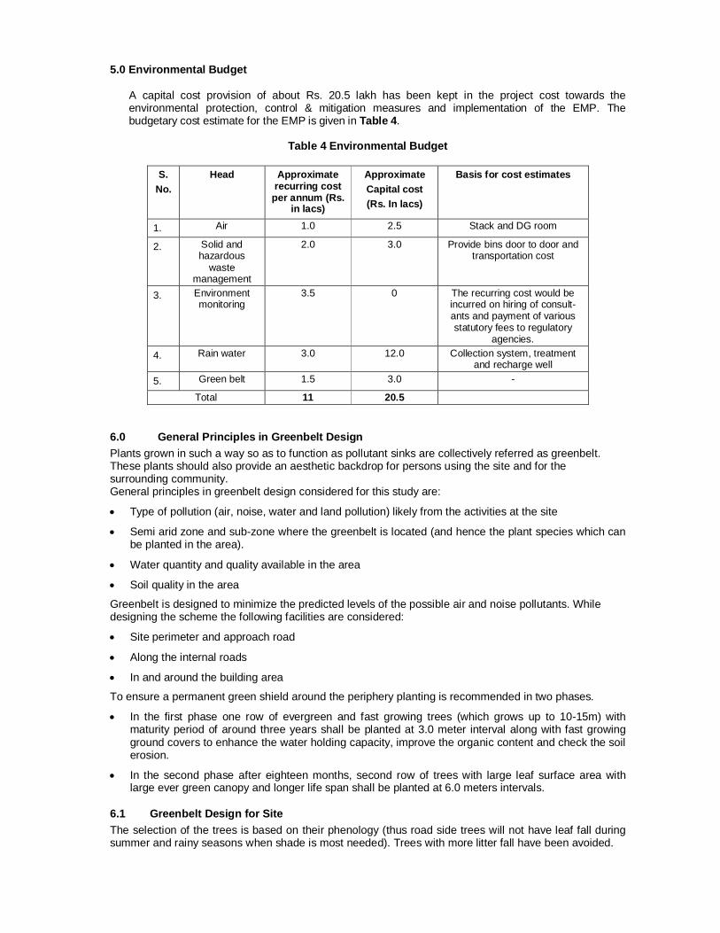
5.0 Environmental Budget
A capital cost provision of about Rs. 20.5 lakh has been kept in the project cost towards the environmental protection, control & mitigation measures and implementation of the EMP. The budgetary cost estimate for the EMP is given in Table 4.
Table 4 Environmental Budget
S.
No. Head Approximate
recurring cost per annum (Rs.
in lacs)
Approximate Capital cost (Rs. In lacs)
Basis for cost estimates
1. Air 1.0 2.5 Stack and DG room
2. Solid and hazardous
waste management
2.0 3.0 Provide bins door to door and transportation cost
3. Environment monitoring
3.5 0 The recurring cost would be incurred on hiring of consult-ants and payment of various statutory fees to regulatory
agencies. 4. Rain water 3.0 12.0 Collection system, treatment
and recharge well 5. Green belt 1.5 3.0 -
Total 11 20.5
6.0 General Principles in Greenbelt Design Plants grown in such a way so as to function as pollutant sinks are collectively referred as greenbelt. These plants should also provide an aesthetic backdrop for persons using the site and for the surrounding community. General principles in greenbelt design considered for this study are:
Type of pollution (air, noise, water and land pollution) likely from the activities at the site
Semi arid zone and sub-zone where the greenbelt is located (and hence the plant species which can be planted in the area).
Water quantity and quality available in the area
Soil quality in the area
Greenbelt is designed to minimize the predicted levels of the possible air and noise pollutants. While designing the scheme the following facilities are considered:
Site perimeter and approach road
Along the internal roads
In and around the building area
To ensure a permanent green shield around the periphery planting is recommended in two phases.
In the first phase one row of evergreen and fast growing trees (which grows up to 10-15m) with maturity period of around three years shall be planted at 3.0 meter interval along with fast growing ground covers to enhance the water holding capacity, improve the organic content and check the soil erosion.
In the second phase after eighteen months, second row of trees with large leaf surface area with large ever green canopy and longer life span shall be planted at 6.0 meters intervals.
6.1 Greenbelt Design for Site The selection of the trees is based on their phenology (thus road side trees will not have leaf fall during summer and rainy seasons when shade is most needed). Trees with more litter fall have been avoided.

The selection criteria of the species are based on pollution mitigation capacity (including particulate matter), large leaf surface area to deep root system and less litter fall. Faster growing trees with lighter canopy will be planted alternatively with relatively slow growing trees with wider canopy. Trees of about 6.0 m heights will be planted at 4.5 m intervals, 2.5 m away from the road curbing as per CPCB guidelines. Trees will be planted along the outer periphery at centerline of road between the set back line and the boundary of the plots. Palms and shrubs will be planted along the roads and around recreational lawns.
6.2 Greenbelt Management It is presumed that the selected plants will be grown as per normal horticultural practice and the authorities responsible for the plantation will make adequate provisions for water and protection of the saplings. A budgetary cost estimate is also prepared for greenbelt development.
Water source Water tankers may also be used at the initial stages of development of the plant.
Irrigation method Water hydrants may be installed at 50 m intervals to irrigate area under shrubs and ground covers.
6.3 Improving Indoor Air Quality The indoor air quality can be improved by any of the following:
Ventilation
Include the use of natural, dilution, local exhaust, or increased ventilation efficiency. The most effective engineering control for prevention of indoor air quality problems is assuring an adequate supply of fresh outdoor air through natural or mechanical ventilation.
When possible, use local exhaust ventilation and enclosure to capture and remove contaminants generated by specific processes. Room air in which contaminants are generated should be discharged directly outdoors rather than recirculated.
Outside air intakes should not be located in close proximity to potential sources of contamination (automobile garages, building exhausts, and roadways).
Work Place Recommendations
Eliminate or control all known and potential sources of microbial contaminants by prompt cleanup and repair of all areas where water collection and leakage has occurred including floors, roofs, drain pans, humidifiers containing reservoirs of stagnant water, air washers etc.
Remove and discard porous organic materials that are contaminated (e.g., damp insulation in ventilation system, ceiling tiles, and carpets).
Clean and disinfect non-porous surfaces where microbial growth has occurred
Maintain indoor air relative humidity below 60%
Adjust intake of outdoor air to avoid contamination from nearby soil, vegetable debris unless air is adequately conditioned.
Isolate, if feasible, areas of renovation, painting, carpet laying, pesticide application, etc., from occupied areas that are not under construction.
Supply adequate ventilation during and after completion of work to assist in diluting the contaminant levels.
Eliminate or reduce contamination of the air supply with cigarette smoke by banning smoking or restricting smoking to designated areas which have their air discharged directly to the outdoor rather than recirculated.
6.4 Safety Aspects of the Project The following needs to be implemented:
Fall Protection
The Contractor is required to provide fall protection to employees who are working at heights equal to or greater than 1.8 m. fall protection can be in the form of perimeter protection such as guardrails and toe rails, personal protective equipment (PPE), a safety monitoring system, or a fall protection plan. Activities that require personal fall protection systems include steel erection bolting, riveting, fitting-up and plumbing-up, work over water and some deep excavation work.
On buildings or structures not adaptable to temporary floors, and where scaffolds are not used, safety nets will be installed and maintained whenever the potential fall distance exceeds two storey.
The PPE standard should cover occupational foot, head, hearing, and eye protection.
Foot Protection: If machines or operations present the potential for foot injury, the Contractor must provide foot protection, which is of safe design and construction for the work to be performed. Workers and visitors should not be allowed on a construction site without safety boots.
Head Protection: If head hazards remain after all steps have been taken to control them (safety nets for work at heights, proper housekeeping), the Contractor must provide employees with appropriate head protection.
Noise Protection: Workers should be wearing hearing protection devices (ear plugs, ear muffs, canal caps) that are in good condition whenever they are involved in noisy activities.
Eye Protection: When machines or operations present potential eye injury from physical or chemical elements, the Contractor must select, provide, maintain and required affected employees to use appropriate eye protection. Eye protection (safety glasses and goggles, face shields and welding helmets) must be adequate and reasonably comfortable.
To the greatest extent possible, working surfaces must be kept dry to prevent slips and falls and to reduce the chance of nuisance odors from pooled water.
All equipment and materials should be stored in designated storage areas that are labeled as such.
Ladders and Stairs
The Contractor is required to inspect and maintain all ladders and temporary/portable steps to ensure that they are in good working condition.
Portable ladders used for access to an upper landing surface must extend a minimum of 1.8 m above the landing surface, or where not practical, be provided with grab rails and be secured against movement while in use.
All ladders must be used only on stable and level surfaces unless secured to prevent accidental movement. Ladders must not be used on slippery surfaces unless secured or provided with slip-resistant feet to prevent accidental movement.
The Contractor should provide a ladder (or stairway) at all work points of access where there is a break in elevation of 0.5 m or more.
When there is only one point of access between levels, it must be kept clear to permit free passage by workers. If free passage becomes restricted, a second point of access must be provided and used. At all times, at least one point of access must be kept clear.
All required stairway and ladder fall protection systems must be provided and installed before employees begin work that requires them to use stairways or ladders.
Scaffolds
Access to Scaffolds - access to and between scaffold platforms more than 0.6 m above or below the point of access will be made by portable/attachable ladders or ramps.
Employees must never use makeshift devices, such as boxes and barrels, to increase the scaffold platform working level height.

Trenching and Excavation
The area around the trench/excavation would be kept clear of surface encumbrances.
Water should not be allowed to accumulate in the excavation.
Adjacent structures would be shored in accordance with the design documents to prevent collapse.
Guardrails or some other means of protecting people from falling into the trench/excavation would be present.
The trench or excavation would be shored or sloped to prevent cave-ins.
Electrical Safety
If work has to be done near an overhead power line, the line must be de-energized and grounded before work is started.
A licensed electrician would have completed all temporary wiring and electrical installations required for construction activities.
Fuses and circuit breakers would be used to protect motherboards, conductors and equipment.
Extension cords for equipment or as part of a temporary wiring system will not be damaged or compromised in any way and insulation must be of the highest grade.
Anytime electrical equipment is deactivated for repair, or circuits are shut off, the equipment will be locked out and tagged at the point where it can be energized.
Temporary lights may not be suspended by their cords.
The Contractor would provide the necessary safety equipment, supplies and monitoring equipment to their personnel.
Cranes A competent person has been designated to supervise activities that require the use of cranes. Cranes would not be operated near any power lines. All picks would be carefully planned to ensure that the crane adequately hoist the load. The hoisting signals would be posted on the exterior of the crane.
Occupational Noise Exposure
The Contractor should implement engineering controls to reduce noise levels.
The Contractor should provide hearing protection to employees that are exposed to noise levels above the permissible limit.
Welding and Cutting
The Contractor's employees would be trained in hot work procedures.
There should be adequate ventilation to reduce the build up of metal fume.
The hot work operators would use proper personal protective equipment (i.e., welding helmet, burning goggles, face shield, welding gloves, and apron).
There would be a fire extinguisher present at all welding and burning activities.
Extinguishers would also be placed at locations where slag and sparks may fall.
Oxygen and flammable gas bottles are separated by at least 7 m when not in use.
The Contractor would control the release of gases, vapors, fumes, dusts, and mists with engineering controls (e.g., adequate ventilation).
General Guidelines
Signs and symbols would be visible during any construction activity that presents a hazard. Upon completion of such activity, the postings must be removed immediately.
The Contractor would post specific DANGER signs when an immediate hazard exists and specific CAUTION signs when the potential for a hazard exists. EXIT, NOTICE and specific safety signs may also be posted in the work area.

Signage for traffic control, including directional signs, is applicable when the Contractor is disrupting traffic along a public way.
Danger signs are posted at all immediate hazards (i.e. Danger: Open Hole).
Caution signs are posted at all potential hazards (i.e. Caution: Construction Area, Caution: Buried Cable).
The floor that is being used as the erection floor must be solidly planked or decked over its entire surface except for access openings.
Every floor, working place and passageway would be kept free from protruding nails, splinters, holes or loose boards.
Combustible scrap and debris (wood, clearing/grubbing material) would be removed from the site daily or should be securely stored in covered containers.
The Contractor would have a spill prevention control and countermeasure plan that limits the risk of releases of oil or hazardous materials to the environment.