Embed Size (px)
Citation preview
M/s Soubhagya Laxmi Sugars Ltd., 1
PREFEASIBILITY
REPORT
for
M/s SOUBHAGYA LAXMI SUGARS LTD
FOR
THE EXPANSION OF 4500 TCD SUGAR INDUSTRY TO 7,500 TCD SUGAR
CANE CRUSHING AND 18 MW COGENERATION UNIT TO 36 MW
COGEENRATION, ESTABLISHMENT OF 60 KLPD DISTILLERY ALONG WITH
INSTALLATION OF INCINERATION BOILER TO GENERATE 3 MW POWER
at
Sy No 413 & 443, Hirenandi, Gokak Taluk, Begaum
PREPARED BY
ENVIRONMENTAL HEALTH & SAFETY CONSULTANTS PRIVATE LTD, # 13/2, 1ST MAIN ROAD, NEAR FIRE STATION, INDUSTRIAL AREA,
RAJAJINAGAR, BANGALORE-560 010, Tele: 080-23012100, Fax: 080 23012111
Email:[email protected]/[email protected] ; www.ehsc.in
M/s Soubhagya Laxmi Sugars Ltd., 2
1. Executive Summary M/s Soubhagya Laxmi Sugars Ltd., have already obtained Environmental Clearance for the establishment of 4500 TCD sugar cane crushing, 18 MW cogeneration unit. Now based on the demand, management has decided to expand the sugar and cogeneration unit project to 7500 TCD sugar cane crushing and 36 MW cogeneration unit, 60 KLPD distillery and 3 MW power by the installation of incineration boiler. Sl.No Items Particulars 1 Objective of the Project Expansion to 7500 TCD of sugar plant with 36
MW Cogeneration unit, establishment of 60 KLPD distillery + installation of incineration boiler to generate 3 MW power.
2 Promoters M/s Soubhagya Laxmi Sugars Ltd 3 Total Investment , Rs 452.5 Crores (Rs. 252.5 Crores for expansion) 4 Project location Sy No 413 & 443 , Hirenandi Village, Gokak
Taluk, Belgaum district 5 Extent of land 426 Acres 6 Man Power 350 7 Water demand and Source for 7500 TCD sugar cane crushing and 36 MW
cogeneration, 60 KLPD distillery and 3 MW from incineration boiler: During season: 1400 KLD During off season: 2476 KLD For 60 KLPD distillery: 600 KLD
8 Power supply The total power required for the proposed project will be 500 kwh – for construction phase from KPTCL During operation phase, for sugar unit: 7.5 MW and for cogeneration unit: during season : 3.0 MW and off season: 4.5 MW. Distillery: 2 MW Power is obtained from Co generation unit
9 Latitude 16 0 03' 29.24" N 10 Longitude 74 0 55' 58.97" E 2. Introduction of the Project/ Background Information
2.1 Identification of project and project proponent.
Soubhagya Laxmi Sugar Ltd (SLSL) is promoted by Shri. Ramesh L Jarkiholi, Chairman along with other two directors. SLSL has appointed key staff and workers for operation of plant. Under the guidence of Chairman with his management team have already carried out several activities in the command area including cane development and activities related to commissioning of sugar plant and cogen power plant Soubhagya Laxmi Sugar Ltd. is a public limited company proposed to expand the sugar and cogeneration unit to 7500 TCD sugars, 36 MW capacity cogen power plant along with installation of 60 KLPD distillery and 3 MW from the installation of incineration boiler. This
M/s Soubhagya Laxmi Sugars Ltd., 3
integrated project will be located at Sy No 413 & 443, Hirenandi Village, Gokak Taluk, Belgaum district. Total land area required is 426 acres of land has been purchased in the name of M/s Soubhagya Laxmi Sugars Ltd.,. Total capital investment on the proposed project is Rs. 452.5 Crores (Rs. 252.5 Crores for expansion). The nearest major village with residential area is Mamdapur, which is at 5.7 kms away from the proposed project site. The commercial & social infrastructure around the proposed site is considered quite well for setting up the proposed integrated project.
The integrated project comprises of a sugar factory for the manufacture of white plantation sugar, thereby making available required bagasse for the cogen power plant. Raw sugar for refinery will be imported. The command area of the proposed sugar mill has excellent irrigation facilities, availability and potential for sustained cane supply & biomass materials like cane trash etc. And imported coal for operating the cogen power plant during off-season.
The aggregated capital investment for the integrated project has been estimated at Rs. 452.5 Crores (Rs. 252.5 Crores for expansion).
2.2. Brief description of nature of the project.
M/s Soubhagya Laxmi Sugars Ltd is located at Sy No 413 & 443 , Hirenandi Village, Gokak Taluk, Belgaum district
The propose sugar complex is to be developed on a land of about 426 acres. This is flat land whereby cutting-filling will be balanced and there will be no/low borrowing from nature.
The area of operation and cane cultivation is mostly irrigated by lifts, wells, and canals, & MI tanks. The climate, soil, rains are favorable for sugarcane growth and sugar cane yield.
2.3. Need for the project and its importance to the country and / or region.
Indian sugar industry is the country's second largest agro processing industry with a production capacity of over 27 million ton of white crystal sugar annually. Majority of the farmers in Maharashtra, Uttar Pradesh and Karnataka are dependent on sugarcane cultivation and sugar industry. Due to increasing irrigation facilities, easy accessibility to modern technology in cultivation and whether forecasting there exist unlimited potential for increasing production as the area under sugar cultivation is only 3 % of the total cultivable area in the country contributing above 7.5 % of the gross values of agricultural production in the country. Above 50 million farmers depend on sugar cane cultivation for their livelihood and equal number of agricultural labourers earns their living by working in sugar cane farms. India requires alcohol for the following three major purposes:
For potable liquor For industrial use For fuel blending
Thus alcohol produced from one source i.e., molasses is used for all 3 purposes. there is an urgent need to bring in above quality consciousness in the industry and appropriate policy measures by the Government. Indian distillery industry broadly consists of two parts:
Production of alcohol from molasses for industrial alcohol Production of alcohol from molasses for liquor purposes.
M/s Soubhagya Laxmi Sugars Ltd., 4
Ethanol demand for fuel blending is a recent phenomenon. For this purposes, alcohol from molasses is used. The potable distillery producing Indian made Foreign Liquor (IMFL) has steady but limited demand. The alcohol produced is now being utilised in the ratio of approximately 52 % for potable purpose and the balance 48 % for industrial purpose.
2.4. Demand-Supply
The existing Sugar factories could not crush all available cane from the areas of operation and hence, rest of the sugarcane is being taken to the sugar factories in neighbouring districts of Karnataka and Maharashtra. Presently, the cane grown by farmers are diverting to the sugar factories located in Maharashtra, in this connection farmers are suffering like delay in disposal, less price, less payment etc., Thus, the farmers are facing problems of disposal of sugarcane in 3-4 seasons. This situation has demanded to need Sugar units at this area. The demand for electrical power has been increasing at a faster pace after the country's economic development the pace speeded up, especially in Karnataka which has been the hub of software services. The effective generation of power has not been meeting the demand and the same trend is expected to continue, especially during the peak hours and summer seasons. Hence, there is good scope for exporting power to the third parties using the state grid through power traders / purchasers.
Since 1977, several technical committees and study groups have examined the issue of blend of ethanol with petrol. Announcement were made on this issue in the Parliament in December 2001, March 2002. Auto fuel policy was declared in august 2002.
The ministry of Petroleum recently issued a gazette notification, dated 11th January 2013 making 5 % ethanol blending with petrol mandatory across the country. the 5 % ethanol blending programme was so far made applicable in only 13 states of the country with blending level of about 2 % against a mandatory target of 5 %, but with this gazette notification it become mandatory for OMCs to achieve 5 % ethanol blending programme for the entire country.
2.5. Imports vs. Indigenous production
Not Applicable
2.6. Export possibility and Domestic / Export markets.
Not applicable. Will be used for domestic use
2.7. Employment Generation (Direct and Indirect) due to the project.
About 350 no of persons of all categories are working in the industry.
3. Project Description
3.1. Type of project including interlinked and interdependent project, if any.
Not applicable
3.2. Location (map showing general location, specific location, and project boundary & project site layout) with coordinates.
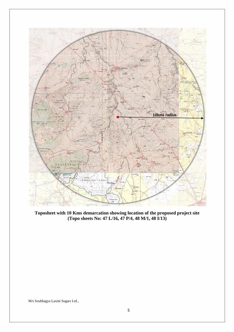
M/s Soubhagya Laxmi Sugars Ltd., 5
Toposheet with 10 Kms demarcation showing location of the proposed project site (Topo sheets No: 47 L/16, 47 P/4, 48 M/1, 48 I/13)
10kms radius
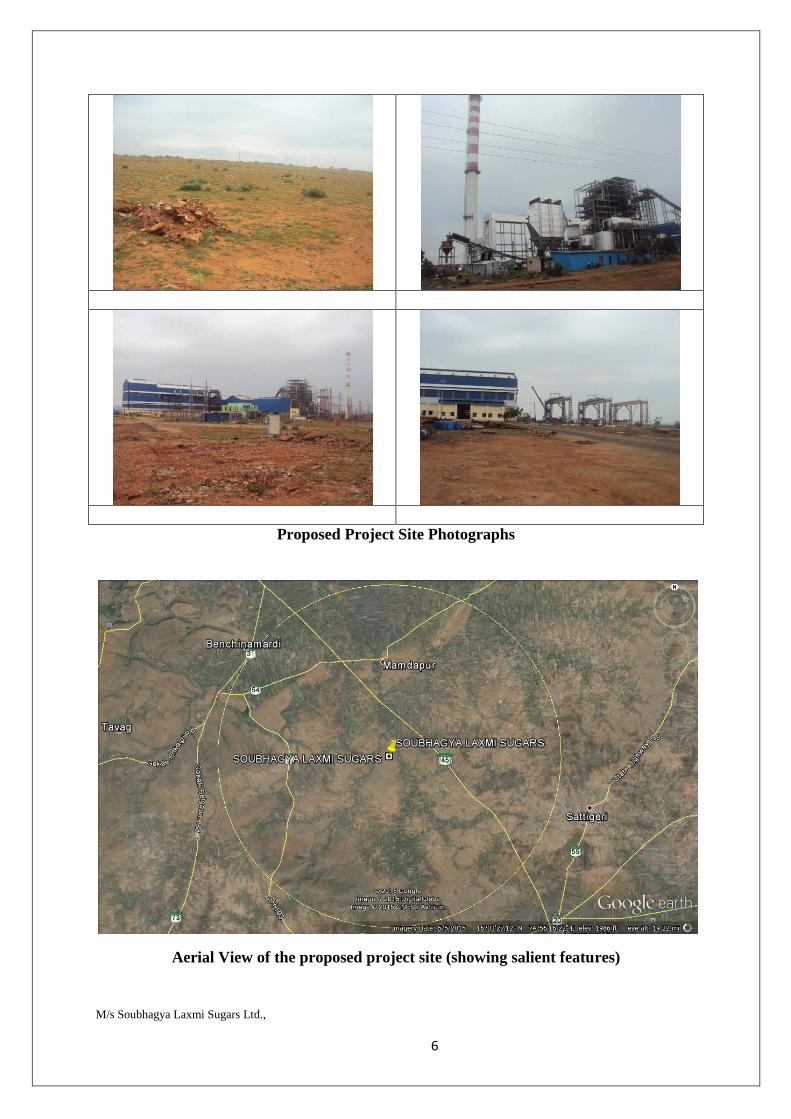
M/s Soubhagya Laxmi Sugars Ltd., 6
Proposed Project Site Photographs
Aerial View of the proposed project site (showing salient features)
M/s Soubhagya Laxmi Sugars Ltd., 7
3.3. Details of alternative sites, considered and the basis of selecting the proposed site particularly the environmental considerations gone into should be highlighted.
Not applicable
3.4. Size & magnitude of operation
The company proposes to expand a sugar complex to 7,500 TCD cane crushing, 36 MW cogen, installation of 60 KLPD distillery + 3 MW from incineration boiler.
3.5. Project description with process details (a schematic diagram/flow chart showing the project layout, components of the project etc) should be given.
PROCESS OF MANUFACTURING:
In India, majority of the factories are involved in preparing white direct consumption sugar, which is 99.8 pure. Some limited quantity of raw or brown sugar (97 - 98 pure) is also made for the purpose of export. Sugar is produced in vacuum pan evaporators. The process of manufacture consists of the following steps:-
1. Extraction of Juice 2. Clarification 3. Evaporation 4. Crystallization 5. Centrifugation 6. Drying 7. Bagging 8. Store 9. Market JUICE EXTRACTION:- There are two methods of juice extraction from the cane. They are MILLING: In this method the cane is passed between heavy rollers to compress the juice, and The cane is crushed immediately after harvesting as the fresh sugar cane gives a higher percentage of yield than the dried cane. In both milling and diffusion processes, the canes are first prepared by breaking the stalk into shorter pieces and making them into small fragments in order to rupture the cane cells which contain juice. For this purpose one set of knives and crusher has been in use but now a large number of factories have installed two sets of knives, one used as a leveler and the other as cutter. These knives are of an engine or electric motor and rotate over a mechanical crusher. The crusher consists of three rollers which are similar to the mills, but equipped with large teeth which are widely spaced, to break the cane so that it feeds more easily in the mills. Shredders are also being used in some factories; they shred the cane into smaller pieces without extracting much juice. In milling process, prepared cane is fed by the cane carrier to a series of mills called milling tandem or train. As the unloaded cane is carried on the cane carrier, the cane chopper controls the cane for even and uniform feeding to the cane leveler where the cane is cut in to pieces by the revolving knives of the leveler. Each mill is fitted with three massive horizontal rollers, with one roller on top and two on the bottom in
M/s Soubhagya Laxmi Sugars Ltd., 8
a triangular shape. These rollers are grooved to allow the extracted juice to flow into juice strainer through the rotary screen placed below. A tandem may have three to five such milling mills. The juice from the first mill is richer than the juice from the second, the juice from the second is richer than the juice from the third, and so on. The fibrous residue of cane that comes out of the last mill is called bagasse. In order to extract the maximum amount of juice from the cane, a process called maceration is practiced. This process consists of weighing water and adding/spraying water at the last mill of the tandem to extract maximum sugar from the bagasse by the method of compound imbibition where the juice extracted by the last mill is added in the third mill and so on. The maceration with water and dilute juices helps in increasing mill efficiency by first diluting the residual juice in the ruptured cane and then extracting it in the subsequent mill. The juice as obtained from the mills is turbid, acidic with a pH range of 5.0 - 5.4, and grey to green in color. It contains 80-90% water, 10-16% sucrose, 0.5-1.5% reducing sugars and about 1.5% non sugars. The non sugars comprise of mineral matter, protein, gums, waxes, tannins, and some pigments in colloidal form. The phosphate content is 100 - 150 mg/l in Maharashtra region and 300 - 450 mg/l in Northern India CLARIFICATION:
This is carried out by two processes viz sulphitation and carbonation process, the former being more in use.
1. Sulphitation Process:
The juice is heated to 700C and milk of lime of 150 be density is added to the extent of 1.0 to 1.5 percent by volume of the juice. Sulphur -di- oxide (S02 content of 8 to 11%) is then passed through the juice to such an extent that the alkalinity produced due to the addition of lime is neutralized. Sulphur-di-oxide gas is produced by burning sulphur in batch or continuous type furnaces. In most of the factories, batch process is followed. The juice may be heated by utilizing the vapors from the evaporators.
The juice is now sent to clarifiers where the precipitated impurities are settled as mud. Clarifiers in use are of continuous type like Dorr clarigester. They contain a number of trays one above the other, dished either towards the center or towards periphery and enclosed in a cylindrical body. On top of clarifier, there is a flocculating chamber at the entrance. The juice flows from the top and passes over these trays thus depositing the muds. Revolving scrappers move the muds towards an outlet, which may be either at the center or around the periphery of trays depending on the design of clarifier. Clarifier is divided in to four compartments each having clear juice draw-offs located at top, while the muddy juice is discharged from the bottom of the tanks. The latter is filtered through cloth in plate and frame type filter press, or through rotary vacuum filter. The clear juices from filtration and from the clarifiers are sent to the evaporators. The rotary vacuum filters, however, gives a turbid juice and hence it has to be returned to the process either in the weighed mixed juice receiving tank or the sulphited juice receiving tank. The mud in the filter presses is washed free from sugar as much as possible, and discarded for use as manure. The washings from filter presses are also added to the clear juice. The purity rise from the mixed to the clear juice in sulphitation process factories is of the order of 0.5 to 1.5 units.
M/s Soubhagya Laxmi Sugars Ltd., 9
2. Carbonation Method:
In this method, Be Haan's process of double carbonation is generally followed. The juice is heated to 50°-55°C and treated with milk of lime (18-20° Be') to the extent of 8-10 percent by volume of juice. Carbon-di-oxide gas is simultaneously passed through the juice in the first set of carbonation tanks. The control of carbonation is done by maintaining the alkalinity of 350-450 mg/I of CaO - lime. The carbon-di- oxide gas (CO2 content 28-30%) is generally produced by burning limestone in Belgian type vertical shaft kilns. The carbonated juice is filtered through cloth in a set of filter presses. The filtered juice along with wash water from the filter presses is again carbonated in the second carbonation tank. The second carbonation is controlled by maintaining a pH of 8.5 to 9.2 corresponding to the minimum CaO content in the second filtered juice. The juice is then heated to 70°C, filtered through a second set of filter presses, and treated with Sulphur-di-oxide gas till it becomes neutral. The neutral juice of pH 6.8 to 7.0 is sent to evaporators. The purity rise from mixed to the clear juice in carbonation process factories is of the order of 4 to 5 units. Various types of filters to give clear juice are now used. Thickening filter consists of rectangular or cylindrical frames covered by cloth bags suspended in a cylindrical vessel, in which the functions of the clarifier and the after filtration are combined in one equipment. This combined equipment gives at the same time a clear filtrate and a mud with higher dry matter content than normally obtained from clarifiers. In contrast to the continuous clarifiers, which cause a lot of inversion due to long detention time of treated juices (3 to 5 hours), the sulphited juice are directly sent to the thickening filters and separated from suspended matter in to 75 to 80 % clear juice free. The mud obtained by the automatic purging system is filtered to rotary vacuum filters, preferably of string discharge type. EVAPORATION: Evaporation is carried out in multiple effect evaporators made up of three, four or five evaporators connected in series. Individual evaporator is called as effects or pans. Each _ of the bodies consists of a closed cylindrical vertical vessel provided with a calenderia or bank of tubes in the annular spaces of which low pressure steam is admitted for heating the juice. The multiple effect system utilizes the latent heat of steam as many times as there are bodies in the system. The bodies are arranged in a series so that each succeeding body has a higher vacuum. The steam enters the calenderia of the first body and the vapors from the boiling juice pass over to calandria of the second body, where because of higher vacuum, the juice boils at a lower temperature, releasing vapors for heating the vapors in the third body and so on. Vapors from the last body go to the multi jet type condenser. The juice moves continuously from one body to the next and finally about 75% of the original water is removed. The thickened juice called syrup contains about 60% or more solids. The syrup obtained from the evaporators are again sulphited by passing Sulphur dioxide gas through it in continuous or batch type syrup sulphiter, in order to bleach it and also to precipitate any lime salt present and thereby improve the quality of sugar. The syrup with or without filtration is sent for crystallization in vacuum pans. CRYSTALLIZATION: The syrup is boiled in vacuum pans to crystallize as massecuite, a mixture of sugar crystals and mother liquor (molasses). Vacuum pans are essentially like a single
M/s Soubhagya Laxmi Sugars Ltd., 10
body of multiple effect evaporator and work in batch operations at high vacuum (660 mm, 54°C boiling point). In order to produce a uniform grade of sugar i.e. the sugar which is virtually of the same color and composition, complex boiling system comprising two to three stages of boiling scheme is practiced. The number of boiling and their techniques used depend upon factors such as the purity of syrup, the grade of sugar desired, and the level of exhaustibility of final molasses required. Boiling of syrup in vacuum pans is a highly skilled operation and is carried out by experienced pan boilers. After a vacuum of 635 mm is achieved in the pan, syrup is drawn in a quantity roughly a quarter of pan. Steam is admitted into the clanderia or the steam coils of the pan and the syrup is boiled to grain. As soon as syrup becomes supersaturated (this is determined either by instruments like cuitometer or from samples drawn by an instrument called proof stick), grain is made to form either by lowering the temperature or more generally by adding seed crystals of fine sugar. The grains are grown sufficiently large by continuous admission of syrup into the pan and progressive boiling under careful manipulation of temperature, steam, and rate of feed of syrup. Care is taken to see that proper graining is formed as this mars the uniformity of size of sugar crystals. Examination· of the boiling syrup is done by drawing samples at regular intervals. In case the false grains appear, these are dissolved out by drawing in some cold water or preferably clarified fresh juice. When the pans are fully boiled to the desired size of the grains, the vacuum is released; and the pan is dropped or struck i.e. the boiling is stopped. The resulting mixture of the grains, called massecuite, is run out of the pan into crystallizers, where residual crystallization continues further. The crystallizers are U-shaped or cylindrical vessels, equipped with cooling and stirring arrangement. CENTRIFUGATION: The partially cooled massecuite from the crystallizer is fed to centrifugal machine revolving at about 1,000 to 1,500 rpm. The baskets of the centrifuges are perforated and a copper screen having fine holes is placed inside the baskets. The mother liquor (molasses) adhering to the crystals goes out of the holes of the screen. A jet of hot water is sprayed at the crystals to free them from molasses, followed by steaming to drive out moisture. The hot moist sugar is discharged into the hoppers fitted below the centrifuges. The sugar from the hoppers is transferred to a long hopper or a cascade type cooler and from there to hot air drum type drier for drying. It is finally shifted to obtain crystals of different size and bagged. The purity of the first massecuite is about 90 per cent and that of the molasses obtained from it is about 70 per cent. The molasses obtained from it, some fresh syrup (or washings from the first massecuite) is again boiled in vacuum pans so as to raise the purity to 76-78%, separated and dried as before. The second molasses with a purity of 53 – 54% is very viscous and as such it is difficult to grain directly. It is conditioned (by slight dilution with water and heating by steam) and mixed with a portion of fully grained syrup, and boiled to form the third massecuite. In this manner the clarified syrup is boiled to three or four massecuites according to the predetermined system of boiling. The final molasses, which may fall 5 to 35 percent or lower purity, is conveyed to the reservoirs, and it constitutes a good source of alcohol. DRYING: After centrifugation from crystallizer, we will get the white crystals of sugar with
M/s Soubhagya Laxmi Sugars Ltd., 11
moisture content. To remove the moisture content of the sugar. crystals, they are passed through rotary drier for drying the crystal to obtain the final product. Drying of Sugar: There are two ways by which sugar is dried in practice
1. Drying sugar in the rotary dryers 2. Drying sugar in the centrifugal machines.
Of the two, drying sugar in the centrifugal machines is considered superior. This is because in the rotary dryers, the crystals lose their luster by the rubbing action against each other. Further, the sugar dust formed means loss of sugar and requires additional equipment to recover it. Drying of sugars and their importance on keeping quality: All sugars undergo microbiological decomposition under humid conditions and consequently there is loss of sugar polarization. This applies to both white consumption sugars as well as raw sugars. The susceptibility for microbiological growth eventually decreases after drying. But as a consequence of drying, polarization of raw sugar increases and this in turn increases its value. In the case of white consumption sugar, its quality lasts longer. Since the moisture content in sugar is regarded as a characteristic of quality, drying has a special significance and is of extreme importance. Modern storage methods, too, such as the introduction of concrete silos, have decisively influenced the demand of sugar drying. The spinning speed of the centrifugal as well as the washing is important for drying. If the moisture of the sugar yielded in the centrifugals is too high, it means that the heat required for drying the sugar increases as well. Sugar that has been insufficiently or badly washed will form at its crystal surface a syrup film with low purity grade. This purity influences to a certain extent the storage capability of the sugar, since the lower is this purity grade, the lesser is the relative equilibrium humidity. The purity of the syrup film also influences the remaining moisture that can be achieved in the sugar. In cases of absolutely pure sugar solutions the relative equilibrium air humidity comes to 85 percent. With impure syrup film the relative equilibrium air humidity amounts to 60% or less. This has been proved by the fact that white sugar from a three boiling system shows a lower degree of moisture content under equal conditions than sugar from a two boiling system. 'Ash' also influences this. Higher 'ash' content determines a higher degree of residual humidity. Other factors influencing the drying process of sugar are the crystal size as well as the proportion of conglomerates. The smaller the size of the crystal, relatively greater will be the adhesiveness of the moisture to such small crystal. For this purpose, drying of finer crystals requires a greater amount of heat. In the case of conglomerates a certain amount of moisture is locked in between the crystals, and larger the crystals the higher the moisture content. Excessive drying of sugar i.e. reducing the moisture to a point, which is below the relative equilibrium moisture of sugar storage unnecessarily, increases the cost of drying. This also leads to the impairment of the sugar quality since the brilliance of the sugar is subdued. Therefore, drying has to be done extremely carefully so as not to impair the quality of the product.
M/s Soubhagya Laxmi Sugars Ltd., 12
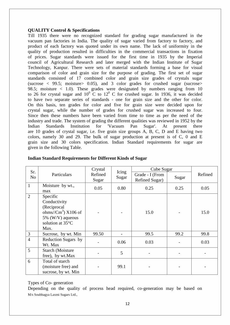
QUALITY Control & Specifications Till 1935 there were no recognized standard for grading sugar manufactured in the vacuum pan factories in India. The quality of sugar varied from factory to factory, and product of each factory was quoted under its own name. The lack of uniformity in the quality of production resulted in difficulties in the commercial transactions in fixation of prices. Sugar standards were issued for the first time in 1935 by the Imperial council of Agricultural Research and later merged with the Indian Institute of Sugar Technology, Kanpur. There were sets of material standards forming a base for visual comparison of color and grain size for the purpose of grading. The first set of sugar standards consisted of 17 combined color and grain size grades of crystals sugar (sucrose < 99.5; moisture> 0.05), and 3 color grades for crushed sugar (sucrose> 98.5; moisture < 1.0). These grades were designated by numbers ranging from 10 to 26 for crystal sugar and 100 C to 120 C for crushed sugar. In 1936, it was decided to have two separate series of standards - one for grain size and the other for color. On this basis, ten grades for color and five for grain size were decided upon for crystal sugar, while the number of grades for crushed sugar was increased to four. Since then these numbers have been varied from time to time as per the need of the industry and trade. The system of grading the different qualities was reviewed in 1952 by the Indian Standards Institution for 'Vacuum Pan Sugar'. At present there are 10 grades of crystal sugar, i.e. five grain size groups A, B, C, D and E having two colors, namely 30 and 29. The bulk of sugar production at present is of C, 0 and E grain size and 30 colors specification. Indian Standard requirements for sugar are given in the following Table. Indian Standard Requirements for Different Kinds of Sugar
Sr. No
Particulars Crystal Refined Sugar
Icing Sugar
Cube Sugar Refined Grade - I (From
Refined Sugar) Sugar
1 Moisture by wt., max
0.05 0.80 0.25 0.25 0.05
2 Specific Conductivity (Reciprocal ohms//Cm3) X106 of 5% (W/V) aqueous solution at 35°C Max.
- - 15.0 - 15.0
3 Sucrose, by wt. Min 99.50 - 99.5 99.2 99.8 4 Reduction Sugars by
Wt. Max - 0.06 0.03 - 0.03
5 Starch (Moisture free), by wt.Max
- 5 - - -
6 Total of starch (moisture free) and sucrose, by wt. Min
- 99.1 - - -
Types of Co- generation Depending on the quality of process head required, co-generation may be based on
M/s Soubhagya Laxmi Sugars Ltd., 13
topping cycle or on bottoming cycle. In bottoming cycle systems, heat is required for the process at high temperature and hence power is generated through a suitable waste heat recovery system. On the other hand, in the topping cycle system, heat is required for the process at low temperatures and therefore power generation is taken up first. Requirement of sugar Industries The process of manufacturing crystal sugar requires steam. In existing co-generation systems steam is generated in low - pressure boilers by using bagasse-the woody fibrous residue of crushed cane, as fuel. This system was developed when possibility of exporting power to the grid was not envisaged. Further, sine the storage of large quantities of combustible bagasse in the premises of the sugar mill was not an advisable option, most of the boilers were designed so as to use almost the entire quantity of bagasse produced. By upgrading the steam parameters, the sugar industry can produce electricity far in excess of their own requirement and sell the surplus power to the grid. Benefits of adopting Co-generation systems in Sugar Industries
Not depending on external power to all, sugar plants can be located nearer the sugar nearer the sugar growing areas, thereby saving on transportation cost of sugarcane.
An efficient and sustained co-generation enables the plant to isolate itself from the vagaries of power.
Power generation using bagasse is environmentally cleaner as bagasse produces very little fly ash and no Sulphur.
Net contribution to greenhouse effect from the bagasse based co-generating plant is zero, since the Carbon-di-oxide absorbed by the sugar cane grown is more than the one emitted by the co-generating plant.
Low capital investment. Recurring costs are also lower compared to fossil fuel based power plants.
Use of totally renewable source of energy. Total saving in the mining, extraction and long distance transportation
expenses of fossil fuels. Rural location of sugar mills enables co-generated power to be directly fed to
the local substation, consequently minimizing T & D. losses and the requirement of long feeder lines.
Saves the expenditure on safe storage and disposal of bagasse. A co-generation plant places no financial or administrative burden on the
utility as it is executed and managed by the sugar factory. Power is generated at a lower cost in co-generating systems and pay back
periods are shorter. Provides an initiative to sugar mills to concentrate more on conservation of
energy and reduction of steam consumption thereby improving their profitability of operation.
Surplus power generation in sugar factory is ideally suited for rural electrification and for energizing irrigation pumps and industrial and agro- based units in the villages.
M/s Soubhagya Laxmi Sugars Ltd., 14
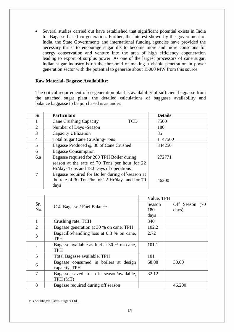
Several studies carried out have established that significant potential exists in India for Bagasse based co-generation. Further, the interest shown by the government of India, the State Governments and international funding agencies have provided the necessary thrust to encourage sugar ills to become more and more conscious for energy conservation and venture into the area of high efficiency cogeneration leading to export of surplus power. As one of the largest processors of cane sugar, Indian sugar industry is on the threshold of making a visible penetration in power generation sector with the potential to generate about 15000 MW from this source.
Raw Material- Bagasse Availability: The critical requirement of co-generation plant is availability of sufficient baggasse from the attached sugar plant, the detailed calculations of baggasse availability and balance baggasse to be purchased is as under. Sr Particulars Details 1 Cane Crushing Capacity TCD 7500 2 Number of Days -Season 180 3 Capacity Utilization 85 4 Total Sugar Cane Crushing-Tons 1147500 5 Bagasse Produced @ 30 of Cane Crushed 344250 6 6.a 7
Bagasse Consumption Bagasse required for 200 TPH Boiler during season at the rate of 70 Tons per hour for 22 Hr/day- Tons and 180 Days of operations Bagasse required for Boiler during off-season at the rate of 30 Tons/hr for 22 Hr/day- and for 70 days
272771 46200
Sr. No.
C.4. Bagasse / Fuel Balance
Value, TPH Season 180 days
Off Season (70 days)
1 Crushing rate, TCH 340 2 Bagasse generation at 30 % on cane, TPH 102.2
3 Bagacillo/handling loss at 0.8 % on cane, TPH
2.72
4 Bagasse available as fuel at 30 % on cane, TPH
101.1
5 Total Bagasse available, TPH 101
6 Bagasse consumed in boilers at design capacity, TPH
68.88 30.00
7 Bagasse saved for off season/available, TPH (MT)
32.12
8 Bagasse required during off season 46,200
M/s Soubhagya Laxmi Sugars Ltd., 15
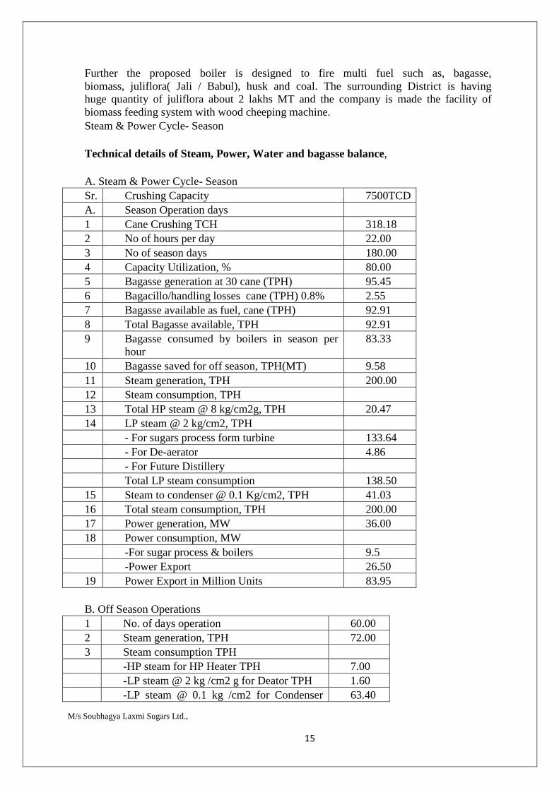
Further the proposed boiler is designed to fire multi fuel such as, bagasse, biomass, juliflora( Jali / Babul), husk and coal. The surrounding District is having huge quantity of juliflora about 2 lakhs MT and the company is made the facility of biomass feeding system with wood cheeping machine. Steam & Power Cycle- Season Technical details of Steam, Power, Water and bagasse balance, A. Steam & Power Cycle- Season Sr. Crushing Capacity 7500TCD A. Season Operation days 1 Cane Crushing TCH 318.18 2 No of hours per day 22.00 3 No of season days 180.00 4 Capacity Utilization, % 80.00 5 Bagasse generation at 30 cane (TPH) 95.45 6 Bagacillo/handling losses cane (TPH) 0.8% 2.55 7 Bagasse available as fuel, cane (TPH) 92.91 8 Total Bagasse available, TPH 92.91 9 Bagasse consumed by boilers in season per
hour 83.33
10 Bagasse saved for off season, TPH(MT) 9.58 11 Steam generation, TPH 200.00 12 Steam consumption, TPH 13 Total HP steam @ 8 kg/cm2g, TPH 20.47 14 LP steam @ 2 kg/cm2, TPH - For sugars process form turbine 133.64 - For De-aerator 4.86 - For Future Distillery Total LP steam consumption 138.50 15 Steam to condenser @ 0.1 Kg/cm2, TPH 41.03 16 Total steam consumption, TPH 200.00 17 Power generation, MW 36.00 18 Power consumption, MW -For sugar process & boilers 9.5 -Power Export 26.50 19 Power Export in Million Units 83.95 B. Off Season Operations 1 No. of days operation 60.00 2 Steam generation, TPH 72.00 3 Steam consumption TPH -HP steam for HP Heater TPH 7.00 -LP steam @ 2 kg /cm2 g for Deator TPH 1.60 -LP steam @ 0.1 kg /cm2 for Condenser 63.40
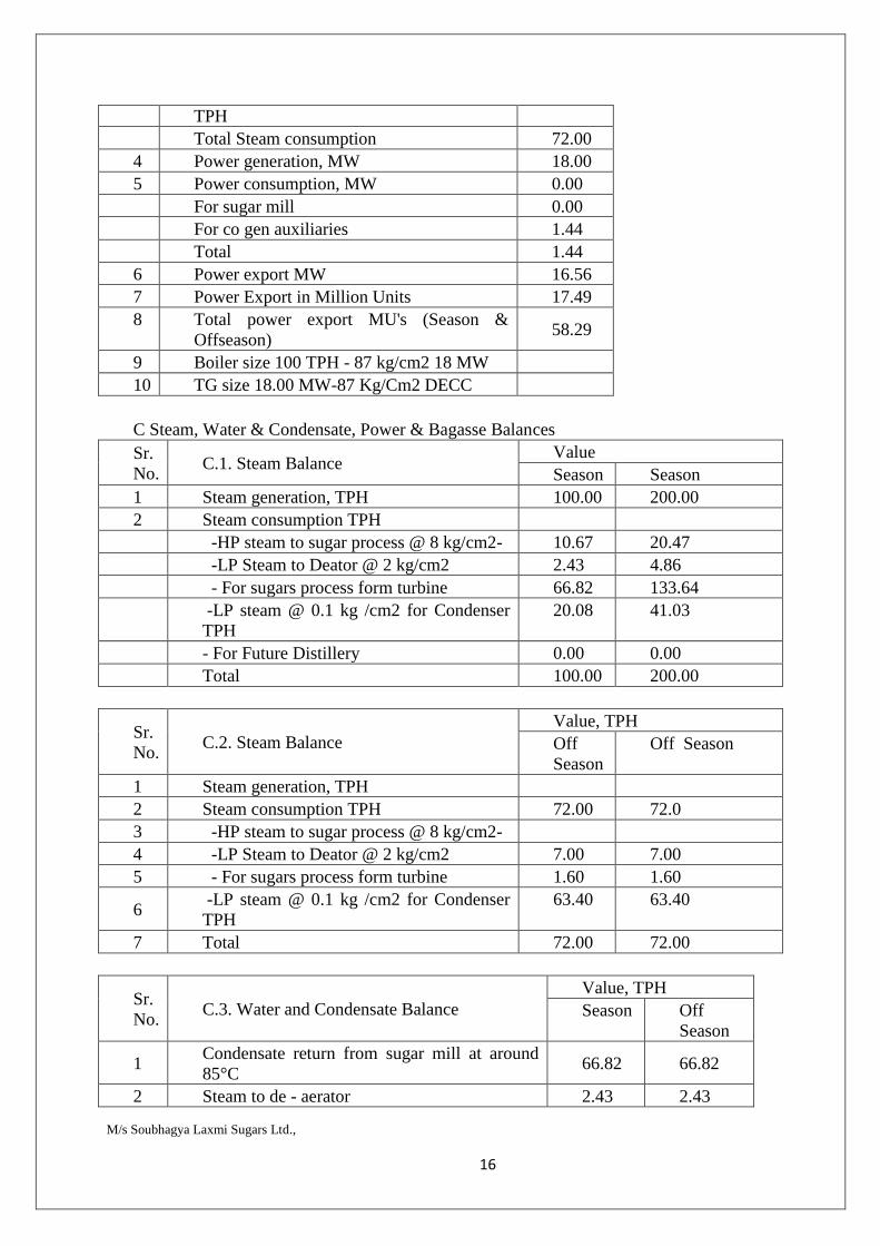
M/s Soubhagya Laxmi Sugars Ltd., 16
TPH Total Steam consumption 72.00 4 Power generation, MW 18.00 5 Power consumption, MW 0.00 For sugar mill 0.00 For co gen auxiliaries 1.44 Total 1.44 6 Power export MW 16.56 7 Power Export in Million Units 17.49 8 Total power export MU's (Season &
Offseason) 58.29
9 Boiler size 100 TPH - 87 kg/cm2 18 MW 10 TG size 18.00 MW-87 Kg/Cm2 DECC C Steam, Water & Condensate, Power & Bagasse Balances Sr. No.
C.1. Steam Balance Value Season Season
1 Steam generation, TPH 100.00 200.00 2 Steam consumption TPH -HP steam to sugar process @ 8 kg/cm2- 10.67 20.47 -LP Steam to Deator @ 2 kg/cm2 2.43 4.86 - For sugars process form turbine 66.82 133.64
-LP steam @ 0.1 kg /cm2 for Condenser TPH
20.08 41.03
- For Future Distillery 0.00 0.00 Total 100.00 200.00
Sr. No.
C.2. Steam Balance Value, TPH Off Season
Off Season
1 Steam generation, TPH 2 Steam consumption TPH 72.00 72.0 3 -HP steam to sugar process @ 8 kg/cm2- 4 -LP Steam to Deator @ 2 kg/cm2 7.00 7.00 5 - For sugars process form turbine 1.60 1.60
6 -LP steam @ 0.1 kg /cm2 for Condenser TPH
63.40 63.40
7 Total 72.00 72.00
Sr. No.
C.3. Water and Condensate Balance Value, TPH Season Off
Season
1 Condensate return from sugar mill at around 85°C
66.82 66.82
2 Steam to de - aerator 2.43 2.43
M/s Soubhagya Laxmi Sugars Ltd., 17
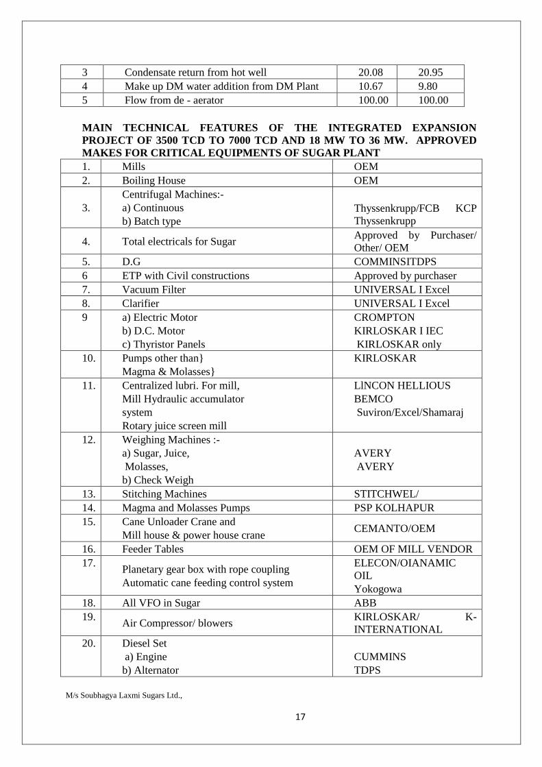
3 Condensate return from hot well 20.08 20.95 4 Make up DM water addition from DM Plant 10.67 9.80 5 Flow from de - aerator 100.00 100.00 MAIN TECHNICAL FEATURES OF THE INTEGRATED EXPANSION PROJECT OF 3500 TCD TO 7000 TCD AND 18 MW TO 36 MW. APPROVED MAKES FOR CRITICAL EQUIPMENTS OF SUGAR PLANT 1. Mills OEM 2. Boiling House OEM
3. Centrifugal Machines:- a) Continuous b) Batch type
Thyssenkrupp/FCB KCP Thyssenkrupp
4. Total electricals for Sugar Approved by Purchaser/ Other/ OEM
5. D.G COMMINSITDPS 6 ETP with Civil constructions Approved by purchaser 7. Vacuum Filter UNIVERSAL I Excel 8. Clarifier UNIVERSAL I Excel 9 a) Electric Motor
b) D.C. Motor c) Thyristor Panels
CROMPTON KIRLOSKAR I IEC KIRLOSKAR only
10. Pumps other than} Magma & Molasses}
KIRLOSKAR
11. Centralized lubri. For mill, Mill Hydraulic accumulator system Rotary juice screen mill
LlNCON HELLIOUS BEMCO Suviron/Excel/Shamaraj
12. Weighing Machines :- a) Sugar, Juice, Molasses, b) Check Weigh
AVERY AVERY
13. Stitching Machines STITCHWEL/ 14. Magma and Molasses Pumps PSP KOLHAPUR 15. Cane Unloader Crane and
Mill house & power house crane CEMANTO/OEM
16. Feeder Tables OEM OF MILL VENDOR 17.
Planetary gear box with rope coupling Automatic cane feeding control system
ELECON/OIANAMIC OIL Yokogowa
18. All VFO in Sugar ABB 19.
Air Compressor/ blowers KIRLOSKAR/ K-INTERNATIONAL
20. Diesel Set a) Engine b) Alternator
CUMMINS TDPS
M/s Soubhagya Laxmi Sugars Ltd., 18
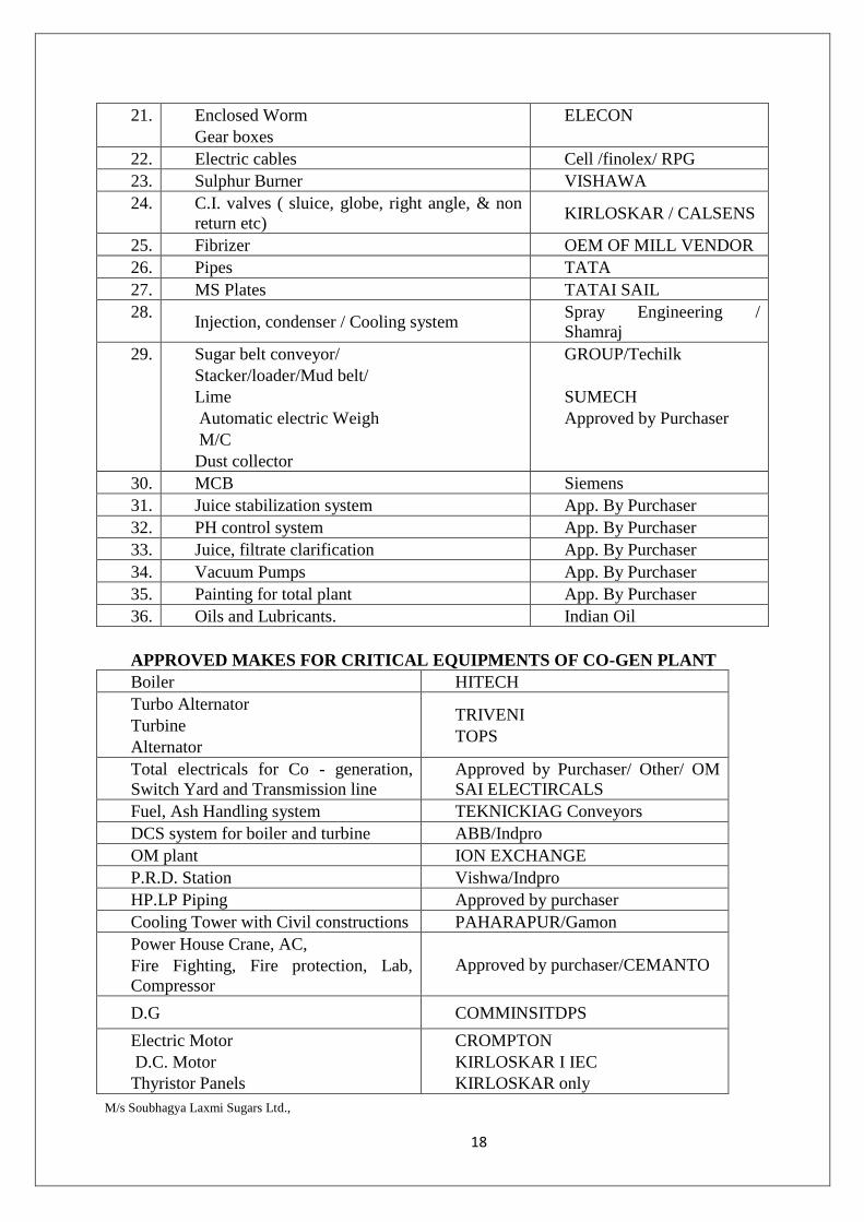
21. Enclosed Worm Gear boxes
ELECON
22. Electric cables Cell /finolex/ RPG 23. Sulphur Burner VISHAWA 24. C.I. valves ( sluice, globe, right angle, & non
return etc) KIRLOSKAR / CALSENS
25. Fibrizer OEM OF MILL VENDOR 26. Pipes TATA 27. MS Plates TATAI SAIL 28.
Injection, condenser / Cooling system Spray Engineering / Shamraj
29. Sugar belt conveyor/ Stacker/loader/Mud belt/ Lime Automatic electric Weigh M/C Dust collector
GROUP/Techilk SUMECH Approved by Purchaser
30. MCB Siemens 31. Juice stabilization system App. By Purchaser 32. PH control system App. By Purchaser 33. Juice, filtrate clarification App. By Purchaser 34. Vacuum Pumps App. By Purchaser 35. Painting for total plant App. By Purchaser 36. Oils and Lubricants. Indian Oil APPROVED MAKES FOR CRITICAL EQUIPMENTS OF CO-GEN PLANT Boiler HITECH Turbo Alternator Turbine Alternator
TRIVENI TOPS
Total electricals for Co - generation, Switch Yard and Transmission line
Approved by Purchaser/ Other/ OM SAI ELECTIRCALS
Fuel, Ash Handling system TEKNICKIAG Conveyors DCS system for boiler and turbine ABB/Indpro OM plant ION EXCHANGE P.R.D. Station Vishwa/Indpro HP.LP Piping Approved by purchaser Cooling Tower with Civil constructions PAHARAPUR/Gamon Power House Crane, AC, Fire Fighting, Fire protection, Lab, Compressor
Approved by purchaser/CEMANTO
D.G COMMINSITDPS
Electric Motor D.C. Motor Thyristor Panels
CROMPTON KIRLOSKAR I IEC KIRLOSKAR only
M/s Soubhagya Laxmi Sugars Ltd., 19
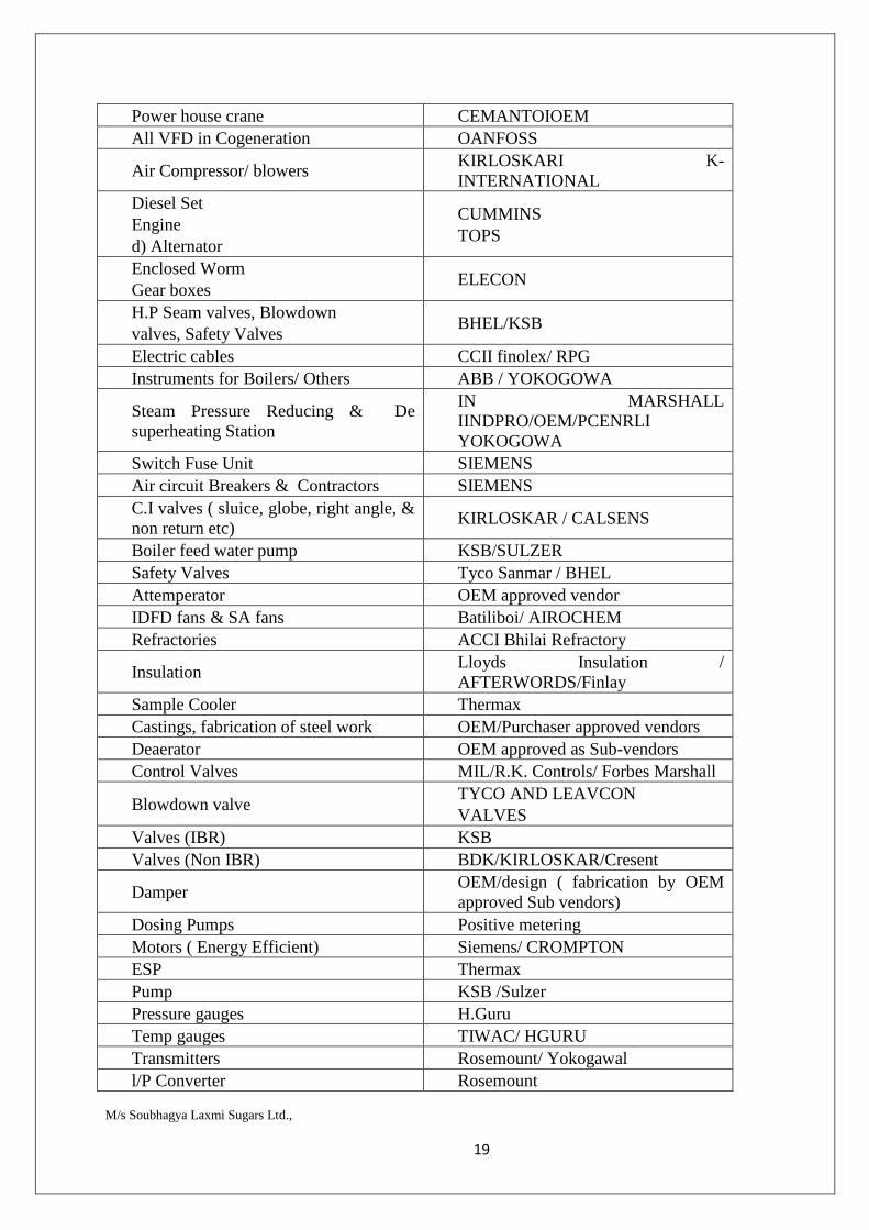
Power house crane CEMANTOIOEM All VFD in Cogeneration OANFOSS
Air Compressor/ blowers KIRLOSKARI K-INTERNATIONAL
Diesel Set Engine d) Alternator
CUMMINS TOPS
Enclosed Worm Gear boxes
ELECON
H.P Seam valves, Blowdown valves, Safety Valves
BHEL/KSB
Electric cables CCII finolex/ RPG Instruments for Boilers/ Others ABB / YOKOGOWA
Steam Pressure Reducing & De superheating Station
IN MARSHALL IINDPRO/OEM/PCENRLI YOKOGOWA
Switch Fuse Unit SIEMENS Air circuit Breakers & Contractors SIEMENS C.I valves ( sluice, globe, right angle, & non return etc)
KIRLOSKAR / CALSENS
Boiler feed water pump KSB/SULZER Safety Valves Tyco Sanmar / BHEL Attemperator OEM approved vendor IDFD fans & SA fans Batiliboi/ AIROCHEM Refractories ACCI Bhilai Refractory
Insulation Lloyds Insulation / AFTERWORDS/Finlay
Sample Cooler Thermax Castings, fabrication of steel work OEM/Purchaser approved vendors Deaerator OEM approved as Sub-vendors Control Valves MIL/R.K. Controls/ Forbes Marshall
Blowdown valve TYCO AND LEAVCON VALVES
Valves (IBR) KSB Valves (Non IBR) BDK/KIRLOSKAR/Cresent
Damper OEM/design ( fabrication by OEM approved Sub vendors)
Dosing Pumps Positive metering Motors ( Energy Efficient) Siemens/ CROMPTON ESP Thermax Pump KSB /Sulzer Pressure gauges H.Guru Temp gauges TIWAC/ HGURU Transmitters Rosemount/ Yokogawal l/P Converter Rosemount
M/s Soubhagya Laxmi Sugars Ltd., 20
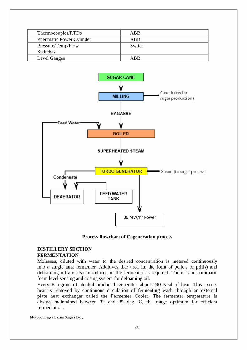
Thermocouples/RTDs ABB Pneumatic Power Cylinder ABB Pressure/Temp/Flow Switches
Switer
Level Gauges ABB
Process flowchart of Cogeneration process
DISTILLERY SECTION FERMENTATION Molasses, diluted with water to the desired concentration is metered continuously into a single tank fermenter. Additives like urea (in the form of pellets or prills) and defoaming oil are also introduced in the fermenter as required. There is an automatic foam level sensing and dosing system for defoaming oil. Every Kilogram of alcohol produced, generates about 290 Kcal of heat. This excess heat is removed by continuous circulation of fermenting wash through an external plate heat exchanger called the Fermenter Cooler. The fermenter temperature is always maintained between 32 and 35 deg. C, the range optimum for efficient fermentation.
36 MW/hr Power
M/s Soubhagya Laxmi Sugars Ltd., 21
The yeast for the fermentation is initially (i.e. during start-up of the plant) developed in the Propagation Section described further on. Once propagated, a viable cell population of about 500 million cells/ml is maintained by yeast recycling and continuous aeration of the fermenter. Fluctuations in the yeast count of +/- 20 % have little effect on the overall fermenter productivity. Yeast cell vitality which is usually above 70% may, in times of stress. (such as prolonged shut-downs) drop to'50% without affecting the fermentation.
Fermented wash passes through a series of hydrocyclones (one to three or move in number depending on plant capacity), which remove grit, iron filings and similar heavy particulate matter. This rejected material along with some wash, is taken to the bottom portion of the wash column for alcohol recovery.
The overflow from the first hydrocyclone is taken a wash tank, also provided with an arrangement to facilitate removal of heavy settable particulate matter. Overflow from the wash tank is taken to the yeast separator, which clarifies the wash. The hydrocyclone and the wash tank protect the separator from erosion damage by removing grit and similar hard particles.
Yeast Recycling: The yeast in the fermented wash is removed as 45 to 55 v/v slurry, and is returned to the fermenter. This feature ensures that a high yeast cell concentration is achieved and maintained in the fermenter. By recirculating grown, active yeast, sugar that would have otherwise been consumed in yeast growth, is made available for ethanol production, ensuring high process efficiency.
Distillation : Clarified or de-yeasted wash flows by gravity to the propagation vessel No. III, which during continuous production, operates as an intermediate wash tank. From here, fermented wash is pumped to the wash preheater, which uses vapours from the rectifying column to preheat wash. Further heating is done in an exchange of heat with weak wash and spent wash (see flow sheet for primary distillation).
Preheated wash then enters the degassifying column of the distillation section.
Primary Distillation: The CO2 and the degassifying section help remove the CO2 and other noncondensables entrained in the wash. The wash column is first column in the distillation section. It is also called the analyser. Wash is boiled in this column with steam either supplied as live steam from the boiler (after pressure reduction and desuperheating ) or from a reboiler which generates steam by evaporating effluent wash.
Alcohol in wash vapourises and is carried, along with water vapour, to the top of the wash column from where it goes to the rectification column. As wash travels down the analyser, it is progressively 'stripped' of its alcohol content. At a point in the column, where the alcohol concentration is 0.5 to 1.0 v/v, a portion of the wash is drawn off. This is called weak wash.
Weak Wash Recycling: Weak wash recycling of weak wash helps maintain the desired level of dissolved solids in the fermenter, so that an adequately
M/s Soubhagya Laxmi Sugars Ltd., 22
high osmotic pressure is achieved. Osmotic pressure and the concentration of alcohol in the fermenter, together keep off infection and minimize sugar losses. Weak wash recycling also reduces the quantity of effluent spent wash and reduces the process water requirement of the plant.
Spent wash is the wash from which all alcohol has been removed, this emerges from the bottom of the wash column at about 105 deg C. Some of the heat is recovered to preheat fermented wash entering the degassifying column.
Spent wash may also be passed through a forced circulation reboiler to generate vapours. This concentrates the effluent and reduces the volume further.
Propagation: The propagation section is a feeder unit to the fermenter. Yeast, either Saccharomyees cereviseae or Schizosaccharomyees pombe (the choice being determined by other process parameters, mainly the downstream effluent treatment system) is grown in 3 stages. The first two stages are designed for aseptic growth. Propagation vessel III develops the inoculum using pasteurized molasses solution as the medium. This vessel has a dual function. During propagation, it serves for inoculum build- up. When the fermenter enters the continuous production mode, Propagation Vessel III is used as an intermediate wash tank. Propagation is carried out only to start up the process initially or after very long shut-downs during which the fermenter is emptied.
CO2 Scrubbing and Recovery: The carbon-di-oxide produced during fermentation is scrubbed with water in packed-bed scrubber, to recover alcohol. The water from the scrubber is returned to the fermenter. About 1.0 % of the total alcohol production is saved by scrubbing the fermenter off gas. In plants where it is desired to recover carbon-di-oxide, a part of the wash is drawn into a separate vessel and is aerated there. This external aeration allows the recovery of CO2 uncontaminated with air. More details of this system can be supplied on request.
Fermentation Parameters (Typical): The pH of the fermenter is maintained between 4.0 & 4.8 usually without addition of any acid. The alcohol concentration is maintained between 7.0 & 7.5 % v/v, unless a highly concentrate effluent is to be produced. To reduce the effluent volume, the fermenter is operated at a very high dissolved solids level by increasing the proportion of weak wash recycle. Under these conditions, alcohol concentration is reduced to between 5.5 to 6.0 % v/v.
Conversion of sugar to ethanol is instantaneous, and the residual sugar concentration is maintained below 0.2 % w/w as glucose. This usually corresponds to a residual reducing substances concentration of 2.0 to 2.5 w/w in wash.
All the nutrient elements necessary for yeast growth exist in adequate quantities as impurities in molasses. Occasionally, Nitrogen may have to be supplemented. Defoaming oil (DFO), say Turkey Red Oil is added to the fermenter by an automated DFO dosing system, to control foaming. Usually no other additives are required.
M/s Soubhagya Laxmi Sugars Ltd., 23
Flexibility: This process accords tremendous flexibility to the operator. Process conditions and plant design can be varied to suit individual requirements of alcohol quality, effluent concentration and characteristics. This unit can give spent wash suitable for use in any effluent treatment process.
2. MULTI PRESSURE VACUUM DISTILLATION:
After fermentation the next stage in the manufacture of alcohol is to separate alcohol from fermented wash and to concentrate it to 95% alcohol called as rectified spirit. For this purpose, distillation process is employed.
Distillation step consumes a considerable amount of energy and is also a deciding factor in the quality of ethanol produced. Hence, in line with the demand of the industry, efforts have always been to minimize requirement of energy and to improve the basic quality of alcohol produced. Ease of operation, reliability, lower down time and flexibility of operations are other parameters considered during the design.
Three basic types of plant are designed: a) One is to produce primary quality of alcohol, usually referred to as 'Rectified Spirit' (R.S.) from the fermented wash. Such plants are also referred to as 'Primary distillation' plants. b) Second is to produce fine quality of spirit usually referred to as 'Extra Neutral Alcohol' (ENA) starting from R.S. Such plants are also referred to as 'secondary distillation' plants. c) Third is to directly produce fine quality alcohol (ENA) from fermented wash. Such plants are referred to as 'wash (mash) to ENA' plants, where the two steps of primary and secondary distillation are combined. Such plants usually have lower consumption of energy than two separate plants. Multi-pressure vacuum distillation system for production of Rectified Spirit /ENA consists of following distillation columns namely 1. Degasifying cum analyzer column - Operation under vacuum 2. Pre-rectification column - Operation under vacuum 3. Rectification cum Exhaust Column - Operated under pressure 4. Recovery column - Operated under atmospheric 5. Extractive distillation column - Operated under vacuum 6. Simmering column - Operated under atmospheric Benefits of Pressure Vacuum Distillation: - Following are the advantages of pressure vacuum distillation. Since the analyzer column operates under vacuum, the formation of by-
products such as acetal may minimize there by improvement in quality of alcohol.
Pre-rectification column ensure removal of sulfur compounds/mercaptans and also reduces load of lower boiling volatile compounds passing on to Rectifier cum exhaust column.
The chances of scaling due to invert solubility of certain precipitating inorganic salts are minimized in vacuum distillation.
Vacuum distillation requires low steam consumption with reboiler
M/s Soubhagya Laxmi Sugars Ltd., 24
Integrated Multi-products Concept: -
It is now possible to install a distillation system, which can produce different products. In the proposed scheme; the production of fuel ethanol has been considered. This allows flexibility of operation and various products can be manufactured depending on the market demand. This integrated multi-product system involves less capital investment as compared to independent system.
In this type of system, switching over from one product to another is quite easy and there is no chance of contamination of one product with another. The system can work under multi-pressure principle with few columns operating under vacuum and few under pressure/atmospheric. 3. Dehydration of Alcohol
Molecular Sieve:
The feed (Rectified Spirit) ,pumped from the storage tanks, Is heated through the heat exchanger by the dehydrated alcohol ,then heated Rs of 93% to 96% is fed to the top of the distillation column.
The liquid passes through the distillation column where ethanol is stripped of. The alcohol free liquid called spent lees is separated and discharged from the bottom of the distillation column and the ethanol stream, with strength of about 96% by volume, is removed as vapor, at the top section of the distillation column and feed to the molecular sieve unit after a super heating about 115°C by steam in the heat exchanger.
Fuel oils are removed from an intermediate point of the column in order to avoid any risk of flooding of the column and feed to the static settling device where are separated from the weak water which are recycled to the column.
The distillation column has an operating pressure of about 160 kPa(A) and is heated with low pressure steam by means of reboiler.
This solution shows following advantages:
Total recovery of steam condensate which is recycled to the steam boiler at high temperature with consequent increasing of the efficiency of the reboiler (higher production of steam per unit of fuel)
Lower cost for softening of demineralization of raw water to be fed to the boiler as steam condensate does not need any treatment
Lower quantity of spillage, potential source of pollution
The super heated ethanol stream removed at the top of the distillation column feeds one of the two sieve beds is now in regeneration mode.
The second sieve bed when in regeneration mode (under vacuum) and receives a small amount of vapour from bed working in over pressure. As soon as regeneration is finished (a regeneration cycle lasts about 5 minutes), an automatic control system changes the operating conditions of the two sieve beds in order to
M/s Soubhagya Laxmi Sugars Ltd., 25
have the first sieve bed in regeneration and the second one in dehydration mode.
The dehydration process releases a vapour ethanol stream with a very small amount of water (500 p.p.m or less), which is condensed in the condensor cooled in the heat exchangers and sent to the storage as dehydrated alcohol. The regeneration process releases a certain amount of absorbed water and ethanol, which are condensed in the condenser and recycled to the column.
Cooling media of the first cooling step of the dehydrated alcohol (condenser) is the regeneration stream recycled to the distillation column and cooling media of the second cooling step of the dehydrated alcohol (condenser) is the fed stock coming from the storage tanks, which is preheated as herein above described. Remaining vapors and liquid are condensed and cooled by cooling water in S & T or P&F heat exchangers. The unit operation is fully automatic and all operations are governed by logics executed by a PLC Control system.
Spent wash treatment
Incineration:
The spent wash which is generated after recovery of alcohol from the distillery is a highly pollutant liquid which will cause great pollution to receiving body like land or water. Hence this needs to be taken care. The latest technology developed to achieve the zero discharge is spent wash incineration boiler. This is a specially designed boiler which will burn the concentrated spent wash along with the coal as supporting fuel. The ratio of this spent wash to coal is 75 : 25.
In this specially designed boiler after burning the spent wash we can generate the steam which is required to run the distillery. In turn, we can save bagasse or coal upto some extent. The calorific value of the concentrated spent wash is 1705 KCal-2000 KCal. Hence this special technology helps us in achieving zero discharge of spent wash. The air pollution causing from this boiler is also very minimum and normal bag house filters can be used as air pollution control equipment to achieve SPM <100µgm/Nm3. The ash collected from the bag filters will be utilized as manure.
This technology helps us in generating steam, power and most important is achieving zero discharge of spent wash.
Salient Features of Incineration boiler:
The proposed Boiler has the following features
The construction of the boiler is such that the fouling potential is minimized through multi- pass design.
The boiler is designed such that it is easily maintainable. The convective section of the boiler (consisting of Economiser, Superheater and
Evaporator) are of vertical tubes. A Steam Coil Air Preheater is provided to preheat combustion air. This is required to
Maintain the bed from quenching. Deep Fluidised bed construction to improve combustion efficiency.
M/s Soubhagya Laxmi Sugars Ltd., 26
Fluidised bed combustor ensures complete combustion. Special On-line cleaning devices are provided. Actual Stack height provided is 68 meters.
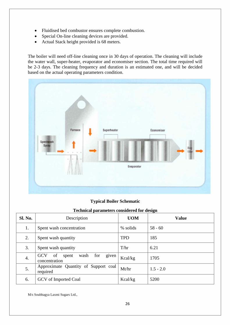
The boiler will need off-line cleaning once in 30 days of operation. The cleaning will include the water wall, super-heater, evaporator and economiser section. The total time required will be 2-3 days. The cleaning frequency and duration is an estimated one, and will be decided based on the actual operating parameters condition.
Typical Boiler Schematic
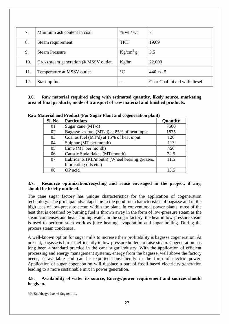
Technical parameters considered for design
Sl. No. Description UOM Value
1. Spent wash concentration % solids 58 - 60
2. Spent wash quantity TPD 185
3. Spent wash quantity T/hr 6.21
4. GCV of spent wash for given concentration
Kcal/kg 1705
5. Approximate Quantity of Support coal required
Mt/hr 1.5 - 2.0
6. GCV of Imported Coal Kcal/kg 5200
M/s Soubhagya Laxmi Sugars Ltd., 27
7. Minimum ash content in coal % wt / wt 7
8. Steam requirement TPH 19.69
9. Steam Pressure Kg/cm2 g 3.5
10. Gross steam generation @ MSSV outlet Kg/hr 22,000
11. Temperature at MSSV outlet °C 440 +/- 5
12. Start-up fuel --- Char Coal mixed with diesel
3.6. Raw material required along with estimated quantity, likely source, marketing area of final products, mode of transport of raw material and finished products.
Raw Material and Product (For Sugar Plant and cogeneration plant)
Sl. No. Particulars Quantity 01 Sugar cane (MT/d) 7500 02 Bagasse as fuel (MT/d) at 85% of heat input 1835 03 Coal as fuel (MT/d) at 15% of heat input 120 04 Sulphur (MT per month) 113 05 Lime (MT per month) 450 06 Caustic Soda flakes (MT/month) 22.5 07 Lubricants (KL/month) (Wheel bearing greases,
lubricating oils etc.) 11.5
08 OP acid 13.5
3.7. Resource optimization/recycling and reuse envisaged in the project, if any, should be briefly outlined.
The cane sugar factory has unique characteristics for the application of cogeneration technology. The principal advantages lie in the good fuel characteristics of bagasse and in the high uses of low-pressure steam within the plant. In conventional power plants, most of the heat that is obtained by burning fuel is thrown away in the form of low-pressure steam as the steam condenses and heats cooling water. In the sugar factory, the heat in low-pressure steam is used to perform such work as juice heating, evaporation and sugar boiling. During the process steam condenses.
A well-known option for sugar mills to increase their profitability is bagasse cogeneration. At present, bagasse is burnt inefficiently in low-pressure boilers to raise steam. Cogeneration has long been a standard practice in the cane sugar industry. With the application of efficient processing and energy management systems, energy from the bagasse, well above the factory needs, is available and can be exported conveniently in the form of electric power. Application of sugar cogeneration will displace a part of fossil-based electricity generation leading to a more sustainable mix in power generation.
3.8. Availability of water its source, Energy/power requirement and sources should be given.

M/s Soubhagya Laxmi Sugars Ltd., 28
Water requirement :
Sugar cane crushing : TCD 7500 Co-gen, MW : 36 Vapour Condensate : 5250
Sl.No Descrption Water consumption
in KLD
Condensate in KLD
Fresh water
in KLD
Recycle in KLD
Losses in
KLD
Effluent generation
in KLD
1 Domestic 14 0 14 0 3 11 A. Sugar
plant
1 Process a. Process
& Cooling (spray pond)
4187 4187 0 0 3885 303
b. E2 condensate water
1298 1298 0 1298 0 0
c. Lab and washing
4 4 0 0 0 4
B. Co-Gen 1 DM plant 858 0 858 343 0 515 2 Cooling
tower 1013 496 517 0 912 101
Total 7373 5985 1389 1641 4724 934 Hence total water requirement for the industry is 7373 KLD out of which 5985 KLD is from the reuse of condensate water. Total fresh water requirement is 1389 KLD
Resource requirement during off season ( after sugar plant opeartion stopped) Sl.No Descrption Water
consumption in KLD
Condensate in KLD
Fresh water
in KLD
Recycle in KLD
Losses in
KLD
Effluent generation
in KLD
1 Domestic 14 0 14 0 3 11 A. Sugar plant 1 Process a. process 0 0 0 0 0 0 b. Cooling (
spary pond, heat exchagers)
0 0 0 0 0 0
Lab and washing
1 0 1 0 0 1
B.

M/s Soubhagya Laxmi Sugars Ltd., 29
1 DM plant 800 0 800 300 0 100 2 Cooling
tower 1662 0 1662 0 1495 166
Total 2476 0 2476 300 1498 278 Fresh water requirement for 10,000 TCD Sugar Cane crushing and 65MW Co-generation During season 1389 During Off season 2476
Distillery: 600 KLD
Sl no Purpose Molasses based operations, m3/day
1 Process and dilution water 300 2 Boiler feed water 60 3 Cooling water 185 4 Washing 15 5 Water treatment Plant 30 6 Domestic 10
Total 600
Power Requirement
For sugar unit: 7.5 MW
For cogeneration - during season: 3 MW
during off season: 4.5 MW
For distillery : 2 MW
The power requirement will be met through cogeneration unit. DG sets are also provided as a backup
3.9. Quantity of wastes to be generated (liquid and solid) and scheme for their Management/disposal.
Effluent generation
Detailed calculation is mentioned earlier
934 KLD Effluent generated will be treated in the ETP of total capacity 1000 KLD and the domestic sewage is disposed to septic tank and soak pit. As 500 KLD ETP exists, extension of the existing ETP will be carried out.
Design Data and Performance Projections The characteristics of the raw effluent considered for designing the plant having UASB followed by Extended Aeration are as follows;
Sl No Parameters Design value 1 Flow 1000 m3/day 2 COD 5000 mg/l 3 BOD 2000 mg/l 4 TSS 800 mg/l
M/s Soubhagya Laxmi Sugars Ltd., 30
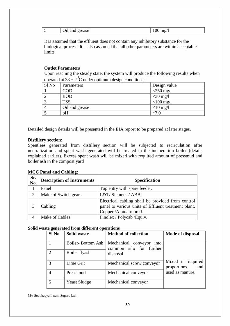
5 Oil and grease 100 mg/l It is assumed that the effluent does not contain any inhibitory substance for the biological process. It is also assumed that all other parameters are within acceptable limits. Outlet Parameters Upon reaching the steady state, the system will produce the following results when operated at 38 ± 2
OC under optimum design conditions;
Sl No Parameters Design value 1 COD <250 mg/l 2 BOD <30 mg/l 3 TSS <100 mg/l 4 Oil and grease <10 mg/l 5 pH ~7.0
Detailed design details will be presented in the EIA report to be prepared at later stages. Distillery section: Spentlees generated from distillery section will be subjected to recirculation after neutralization and spent wash generated will be treated in the incineration boiler (details explained earlier). Excess spent wash will be mixed with required amount of pressmud and boiler ash in the compost yard MCC Panel and Cabling:
Sr. No. Description of Instruments Specification
1 Panel Top entry with spare feeder. 2 Make of Switch gears L&T/ Siemens / ABB
3 Cabling Electrical cabling shall be provided from control panel to various units of Effluent treatment plant. Copper /Al unarmored.
4 Make of Cables Finolex / Polycab /Equiv. Solid waste generated from different operations
Sl No Solid waste Method of collection Mode of disposal
1 Boiler- Bottom Ash Mechanical conveyor into common silo for further disposal
Mixed in required proportions and used as manure.
2 Boiler flyash
3 Lime Grit Mechanical screw conveyor
4 Press mud Mechanical conveyor
5 Yeast Sludge Mechanical conveyor
M/s Soubhagya Laxmi Sugars Ltd., 31
6 Sludge from ETP Sludge drying beds
7 Used oil from DG sets
Stored in leakproof sealed barrels
Used as lubricants within the industry
8 Waste oil residue from ETP
• Domestic Solid waste (Garbage/ Trash/ garden litters) will be stored in Garbage collection pits and disposed off by using proper disposal mechanism
• Used Oil generated from the industry will be collected and stored in barrels/drums and later disposed to the Karnataka State Pollution Control Board approved waste oil reprocessors/dealers.
• Any other solid waste generated from the facility will be disposed off by using proper disposal mechanism.
3.10. Schematic representations of the feasibility drawing which give information of EIA purpose
As per EIA notification , 2006 and further amendments the proposal is 5(g)- 60 KLPD distillery 5 (j)- 7500 TCD sugar cane crushing, 1 (d)- 36 MW cogeneration unit based on biomass (such as bagasse)
4. Site Analysis
4.1. Connectivity
The proposed sugar factory will be located at Sy No 413 & 443 , Hirenandi Village, Gokak Taluk, Belgaum district Gokak is second biggest city after Belgaum in Belgaum district and is surrounded by the Western Ghats. The Ghataprabha River, which has water almost throughout the year, is the chief source of agricultural and drinking water for local people living in the surrounding villages. Gokak is located at 16.67°N 74.83°E. It has an average elevation of 553 metres (1814 feet). The city is situated in the central part of Belgaum district which is located in northwestern parts of Karnataka and lies at the border of two states, Maharashtra in the north and Goa on the west. It is located at a distance of 540 km from Bangalore which is the capital city of the state of Karnataka. Gokak comes under Tropical deciduous moist belt in south central India. Majority of the soil in Gokak taluka is composed of Laterite soil and small amounts of Black soil is found as well Gokak city situated at 16 Km from site and is well connected by road and rail. The nearest railway station for the factory is at Gokak which is about 26 Kms from site towards NW. The nearest airport is Belgaum about 29.4 Km. Nearest sea port is Goa. There are no protected monuments within a distance of 25.0 Km. This is one of the units among the several Sugar plants, which have come up in Karnataka State in recent years.

M/s Soubhagya Laxmi Sugars Ltd., 32
4.2. Land form, land use and land ownership.
The site is situated at Sy No 413 & 443, Hirenandi Village, Gokak Taluk, Belgaum district.
4.3. Topography (along with map)
View of the proposed project site
Aerial View of the Proposed Project Site Showing 10 Kms Radius Demarcation
Project site
M/s Soubhagya Laxmi Sugars Ltd., 33
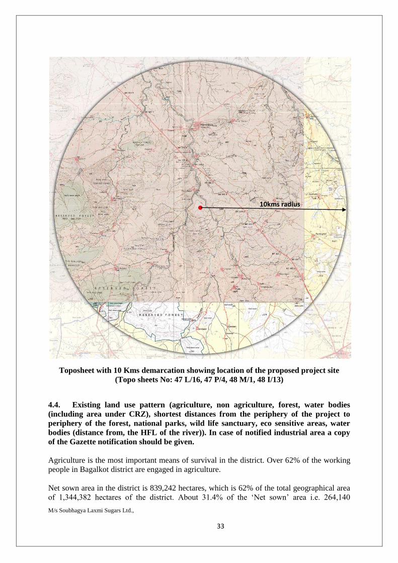
Toposheet with 10 Kms demarcation showing location of the proposed project site (Topo sheets No: 47 L/16, 47 P/4, 48 M/1, 48 I/13)
4.4. Existing land use pattern (agriculture, non agriculture, forest, water bodies (including area under CRZ), shortest distances from the periphery of the project to periphery of the forest, national parks, wild life sanctuary, eco sensitive areas, water bodies (distance from, the HFL of the river)). In case of notified industrial area a copy of the Gazette notification should be given.
Agriculture is the most important means of survival in the district. Over 62% of the working people in Bagalkot district are engaged in agriculture.
Net sown area in the district is 839,242 hectares, which is 62% of the total geographical area of 1,344,382 hectares of the district. About 31.4% of the ‘Net sown’ area i.e. 264,140
10kms radius
M/s Soubhagya Laxmi Sugars Ltd., 34
hectares is sown more than once (Table-3). Major crops grown in the area are jowar, maize, paddy, wheat, bajra, grams, tur, groundnut, sunflower, sugarcane, cotton, tobacco etc.
4.5. Existing Infrastructure
The proposed sugar factory will be located at Sy No 413 & 443 , Hirenandi Village, Gokak Taluk, Belgaum district Gokak is second biggest city after Belgaum in Belgaum district and is surrounded by the Western Ghats. The Ghataprabha River, which has water almost throughout the year, is the chief source of agricultural and drinking water for local people living in the surrounding villages. Gokak is located at 16.67°N 74.83°E. It has an average elevation of 553 metres (1814 feet). The city is situated in the central part of Belgaum district which is located in northwestern parts of Karnataka and lies at the border of two states, Maharashtra in the north and Goa on the west. It is located at a distance of 540 km from Bangalore which is the capital city of the state of Karnataka. Gokak comes under Tropical deciduous moist belt in south central India. Majority of the soil in Gokak taluka is composed of Laterite soil and small amounts of Black soil is found as well Gokak city situated at 16 Km from site and is well connected by road and rail. The nearest railway station for the factory is at Gokak which is about 26 Kms from site towards NW. The nearest airport is Belgaum about 29.4 Km. Nearest sea port is Goa. There are no protected monuments within a distance of 25.0 Km.
4.6. Soil Classification
Majority of the soil in Gokak taluka is composed of Laterite soil and small amounts of Black soil is found as well.
Dry type of vegetation is generally found in the central and eastern parts of Belgaum district. Domestic animals which are directly dependent on plants can be found in the region. They are used for agricultural as well as transportation purposes in rural areas. Ground water resources are also extensively tapped in remote areas which are not eaisly accessible to canals and rivers. It has also been found that about 40% of area in Belgaum district has a higher concentration of nitrates in drinking water due to extensive dependency onfertilisers for agriculture. According to a geological survey, ground water in Gokak has a pH of about 8.6 with desirable limits being 6.5 to 8.5. The region around Gokak contains large quantities of Gneisses rock which ultimately gives rise to clay deposits. Region lying to the north of Gokak consist of Sandstones and Quartzite that form low ridges. The Manganese deposits occur in Belgaum district between Londa and Gokak taluka. Building stones and moulding sand are available around Khanapur & Gokak in Belgaum district.
4.7. Climatic and Rainfall data from secondary sources Being situated in central region of Belgaum district which lies in the rugged terrain of north-western Karnataka, Gokak is known for its moderately hot climate throughout the year except for the monsoon. Gokak receives rainfall from both the northeast and the southwest monsoons and the wettest months are June–September. It has a distinct wet and dry season. December & January are generally cold as compared to the rest of year. The coldest month is January with an average low temperature of 15.2 °C and the hottest month is April with an average high temperature of 35.7 °C. Winter temperatures rarely drop below 14 °C (54 °F), and summer temperatures seldom exceed 34–35 °C.
M/s Soubhagya Laxmi Sugars Ltd., 35
4.8. Social Infrastructure available
The proposed sugar factory will be located at Sy No 413 & 443 , Hirenandi Village, Gokak Taluk, Belgaum district. Majority of public transport in Gokak connecting surrounding villages and towns is through city buses run by NWKRTC from Gokak bus depot. Auto rickshaws are commonly available at a nominal fare for commuting inside the city. Road Gokak is connected by road via State Highway 31 (Jath to Jamboti) and to National Highway 4 (India) (exit at Hattargi cross). NWKRTC which is a sub-division of KSRTC runs buses from Gokak to all corners of Karnataka as well as neighbouring states. There are many prominent private bus services which operate across all major destinations inKarnataka, Goa and Maharashtra. The other state highways passing through Gokak are State Highway 44 (Sankeshwar to Sangam), State Highway 45 (Arabhavi to Challakere), State Highway 103 (Gokak to Saundatti), State Highway 134 (Badami to NH 4 at Hattargi Cross) Rail Gokak Road and Ghataprabha are the two main railway stations near Gokak located at a distance of about 12 km and 14 km respectively and 26 kms and 27 kms from the project site. These stations fall under Indian Railways grid and are a part of south western division. Hubli junction (UBL) and Miraj junction (MRJ) which come under South Western Railway Zone and Central Railway Zoneare the closest railway junctions to Gokak Road station. They are well connected to major cities like Bangalore, Mysore, Mangalore, Pune, Mumbai, Hyderabad, Goa, New Delhi and Chennai. Air ( Belgaum - Bagalkot Road ). The nearest airport is Belgaum about 16 Km. Nearest sea port is Goa. There are no protected monuments within a distance of 25.0 Km. 5. Planning
5.1. Planning concept (type of industries, facilities, transportation, etc.,) Town and Country Planning Development authority classification.
The proposed sugar factory will be located at at Sy No 413 & 443 , Hirenandi Village, Gokak Taluk, Belgaum district Gokak is second biggest city after Belgaum in Belgaum district and is surrounded by the Western Ghats. The Ghataprabha River, which has water almost throughout the year, is the chief source of agricultural and drinking water for local people living in the surrounding villages. Gokak is located at 16.67°N 74.83°E. It has an average elevation of 553 metres (1814 feet). The city is situated in the central part of Belgaum district which is located in northwestern parts of Karnataka and lies at the border of two states, Maharashtra in the north and Goa on the west. It is located at a distance of 540 km from Bangalore which is the capital city of the state of Karnataka. Gokak comes under Tropical deciduous moist belt in south central India. Gokak city situated at 16 Km from site and is well connected by road and rail.
M/s Soubhagya Laxmi Sugars Ltd., 36
The nearest railway station for the factory is at Gokak which is about 26 Kms from site towards NW. The nearest airport is Belgaum about 29.4 Km. Nearest sea port is Goa. There are no protected monuments within a distance of 25.0 Km.
5.2. Population Projection:
An official Census 2011 detail of Belgaum, a district of Karnataka has been released by Directorate of Census Operations in Karnataka. Enumeration of key persons was also done by census officials in Belgaum District of Karnataka. In 2011, Belgaum had population of 4,779,661 of which male and female were 2,423,063 and 2,356,598 respectively. In 2001 census, Belgaum had a population of 4,214,505 of which males were 2,150,090 and remaining 2,064,415 were females. Belgaum District population constituted 7.82 percent of total Maharashtra population. In 2001 census, this figure for Belgaum District was at 7.97 percent of Maharashtra population. There was change of 13.41 percent in the population compared to population as per 2001. In the previous census of India 2001, Belgaum District recorded increase of 17.61 percent to its population compared to 1991.
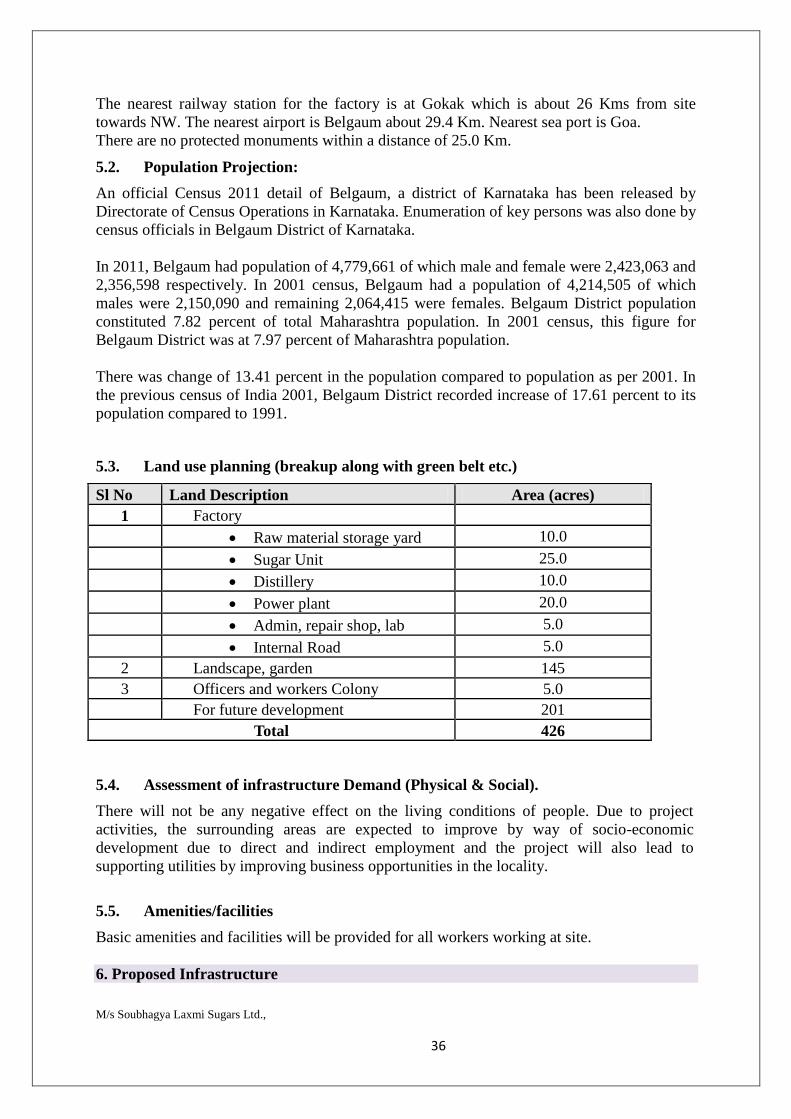
5.3. Land use planning (breakup along with green belt etc.)
Sl No Land Description Area (acres) 1 Factory
Raw material storage yard 10.0 Sugar Unit 25.0 Distillery 10.0 Power plant 20.0 Admin, repair shop, lab 5.0 Internal Road 5.0
2 Landscape, garden 145 3 Officers and workers Colony 5.0 For future development 201
Total 426
5.4. Assessment of infrastructure Demand (Physical & Social).
There will not be any negative effect on the living conditions of people. Due to project activities, the surrounding areas are expected to improve by way of socio-economic development due to direct and indirect employment and the project will also lead to supporting utilities by improving business opportunities in the locality.
5.5. Amenities/facilities
Basic amenities and facilities will be provided for all workers working at site. 6. Proposed Infrastructure
M/s Soubhagya Laxmi Sugars Ltd., 37
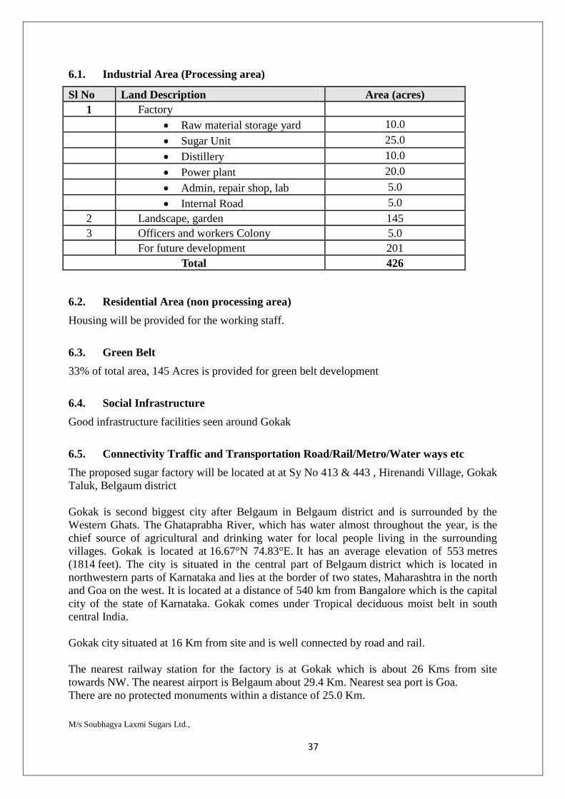
6.1. Industrial Area (Processing area)
Sl No Land Description Area (acres) 1 Factory
Raw material storage yard 10.0 Sugar Unit 25.0 Distillery 10.0 Power plant 20.0 Admin, repair shop, lab 5.0 Internal Road 5.0
2 Landscape, garden 145 3 Officers and workers Colony 5.0 For future development 201
Total 426
6.2. Residential Area (non processing area)
Housing will be provided for the working staff.
6.3. Green Belt
33% of total area, 145 Acres is provided for green belt development
6.4. Social Infrastructure
Good infrastructure facilities seen around Gokak
6.5. Connectivity Traffic and Transportation Road/Rail/Metro/Water ways etc
The proposed sugar factory will be located at at Sy No 413 & 443 , Hirenandi Village, Gokak Taluk, Belgaum district Gokak is second biggest city after Belgaum in Belgaum district and is surrounded by the Western Ghats. The Ghataprabha River, which has water almost throughout the year, is the chief source of agricultural and drinking water for local people living in the surrounding villages. Gokak is located at 16.67°N 74.83°E. It has an average elevation of 553 metres (1814 feet). The city is situated in the central part of Belgaum district which is located in northwestern parts of Karnataka and lies at the border of two states, Maharashtra in the north and Goa on the west. It is located at a distance of 540 km from Bangalore which is the capital city of the state of Karnataka. Gokak comes under Tropical deciduous moist belt in south central India. Gokak city situated at 16 Km from site and is well connected by road and rail. The nearest railway station for the factory is at Gokak which is about 26 Kms from site towards NW. The nearest airport is Belgaum about 29.4 Km. Nearest sea port is Goa. There are no protected monuments within a distance of 25.0 Km.
M/s Soubhagya Laxmi Sugars Ltd., 38
6.6. Drinking Water Management (Source & Supply of water)
Drinking water is met through MI tanks located at Hanumapur located at 5.5 kms from the site followed by treatment in the water treatment plant at the site.
6.7. Sewerage System
Domestic sewage is treated in septic tank and soak pit. Industrial effluent will be treated in the ETP through internal sewer network
6.8. Industrial Waste Management
Effluent generated will be treated in the ETP of 1000 KLD and treated water will be used within the plant premises.
6.9. Solid Waste Management
Solid waste generated from the industry include Pressmud, ash from sugar industry which is used mixed in the required proportions and sold as manure. Bagasse generated will be used as fuel in the cogeneration boiler.
6.10. Power Requirement & Supply/Source
Power requirement will be met through cogeneration
7. Rehabilitation and Resettlement (R&R) Plan
7.1. Policy to be adopted (Central/State) in respect of the project affected persons including home oustees, land oustees, and landless labourers (a brief outline to be given).
Not applicable. 8. Project Schedule & Cost Estimation
8.1. Project Schedule
Expansion of a sugar complex to 7500 TCD sugar cane, 36 MW cogeneration unit based on biomass (such as bagasse), 60 KLPD distillery + 3 MW power from incineration boiler
8.2. Cost Estimates
Rs. 452.5 Crores as estimated
9. Analysis of proposal (Final recommendation)
9.1. Financial and social benefits with special emphasis on the benefit to the local people including tribal population, if any, in the area
350 nos, the company provides all necessary basic amenities to the workers of the industry.