Embed Size (px)
Citation preview
WYN C0-8940 1/16
AHU Controller Specifications 1. Application
This controller is used to set up a system by connecting a field-supplied Air Handling Unit (AHU) to Mitsubishi Electric City Multi outdoor unit. Applicable models: PAC-AH125, 140, and 250M-H
2. System restrictions and use of range
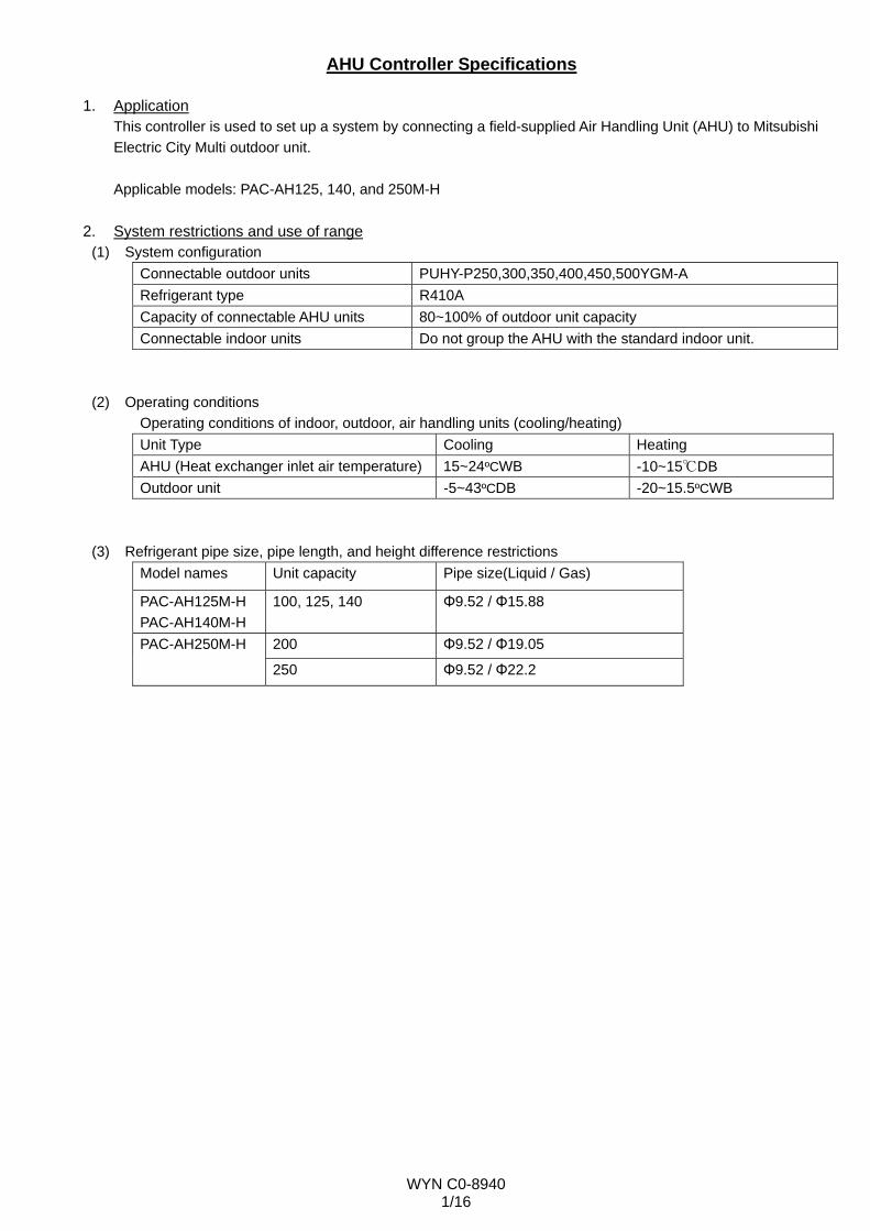
(1) System configuration Connectable outdoor units PUHY-P250,300,350,400,450,500YGM-A Refrigerant type R410A Capacity of connectable AHU units 80~100% of outdoor unit capacity Connectable indoor units Do not group the AHU with the standard indoor unit.
(2) Operating conditions Operating conditions of indoor, outdoor, air handling units (cooling/heating) Unit Type Cooling Heating AHU (Heat exchanger inlet air temperature) 15~24ºCWB -10~15℃DB Outdoor unit -5~43ºCDB -20~15.5ºCWB
(3) Refrigerant pipe size, pipe length, and height difference restrictions Model names Unit capacity Pipe size(Liquid / Gas)
PAC-AH125M-H PAC-AH140M-H
100, 125, 140 Φ9.52 / Φ15.88
200 Φ9.52 / Φ19.05 PAC-AH250M-H
250 Φ9.52 / Φ22.2
WYN C0-8940 2/16
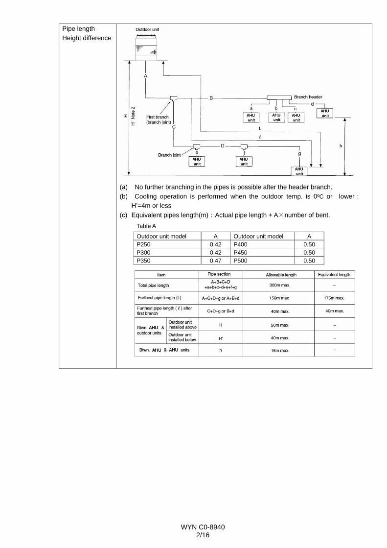
Pipe length Height difference
(a) No further branching in the pipes is possible after the header branch. (b) Cooling operation is performed when the outdoor temp. is 0ºC or lower:
H’=4m or less (c) Equivalent pipes length(m):Actual pipe length + A×number of bent.
Table A
Outdoor unit model A Outdoor unit model A P250 0.42 P400 0.50 P300 0.42 P450 0.50 P350 0.47 P500 0.50
WYN C0-8940 3/16
Amount of refrigerant to be added
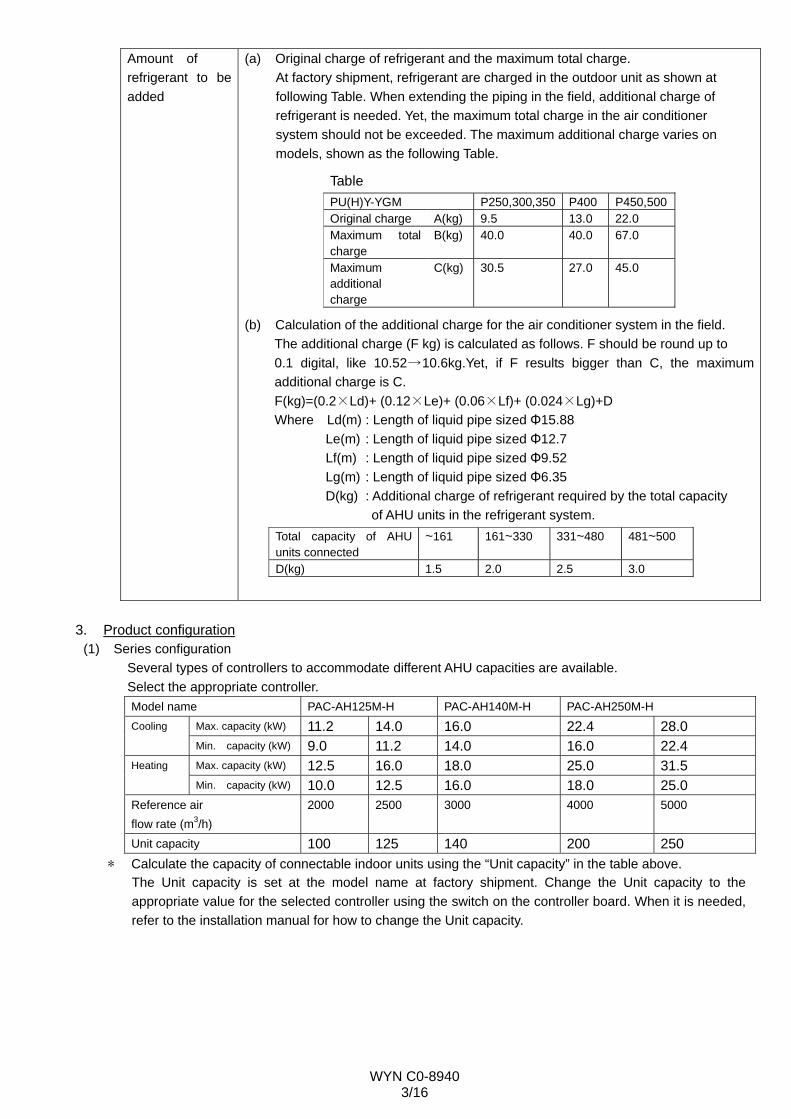
(a) Original charge of refrigerant and the maximum total charge. At factory shipment, refrigerant are charged in the outdoor unit as shown at following Table. When extending the piping in the field, additional charge of refrigerant is needed. Yet, the maximum total charge in the air conditioner system should not be exceeded. The maximum additional charge varies on models, shown as the following Table.
Table PU(H)Y-YGM P250,300,350 P400 P450,500Original charge A(kg) 9.5 13.0 22.0 Maximum total charge
B(kg) 40.0 40.0 67.0
Maximum additional charge
C(kg) 30.5 27.0 45.0
(b) Calculation of the additional charge for the air conditioner system in the field.
The additional charge (F kg) is calculated as follows. F should be round up to 0.1 digital, like 10.52→10.6kg.Yet, if F results bigger than C, the maximum additional charge is C. F(kg)=(0.2×Ld)+ (0.12×Le)+ (0.06×Lf)+ (0.024×Lg)+D Where Ld(m) : Length of liquid pipe sized Φ15.88 Le(m) : Length of liquid pipe sized Φ12.7 Lf(m) : Length of liquid pipe sized Φ9.52 Lg(m) : Length of liquid pipe sized Φ6.35 D(kg) : Additional charge of refrigerant required by the total capacity of AHU units in the refrigerant system. Total capacity of AHU units connected
~161 161~330 331~480 481~500
D(kg) 1.5 2.0 2.5 3.0
3. Product configuration
(1) Series configuration Several types of controllers to accommodate different AHU capacities are available. Select the appropriate controller. Model name PAC-AH125M-H PAC-AH140M-H PAC-AH250M-H
Max. capacity (kW) 11.2 14.0 16.0 22.4 28.0 Cooling
Min. capacity (kW) 9.0 11.2 14.0 16.0 22.4 Max. capacity (kW) 12.5 16.0 18.0 25.0 31.5 Heating
Min. capacity (kW) 10.0 12.5 16.0 18.0 25.0 Reference air flow rate (m3/h)
2000 2500 3000 4000 5000
Unit capacity 100 125 140 200 250 * Calculate the capacity of connectable indoor units using the “Unit capacity” in the table above.
The Unit capacity is set at the model name at factory shipment. Change the Unit capacity to the appropriate value for the selected controller using the switch on the controller board. When it is needed, refer to the installation manual for how to change the Unit capacity.
WYN C0-8940 4/16
(2) Controller components Name Usage
Controller board For operation control Transformer For controller board Terminal block For power source, for external I/O, for internal and external
communication, for remote controller, and for thermistor Connector For remote controller and for level input switch
Controller
Relay For operation display and for error display LEV-kit Electronic linear expan. valve Thermistor For detection of suction air temperature, discharge temperature,
liquid pipe temperature, and gas pipe temperature Clip For mounting suction air and discharge air temperature
thermistor Insulation For insulating liquid pipe and gas pipe thermistor Tie band For fixing liquid pipe and gas pipe thermistor Tube For fixing wiring Installation manual -
(3) Major specifications
Power supply 208~240V 50/60Hz External dimension (mm) 382(430)×326×117(132)
The figure in ( ) indicates mounting's. Net weight (kg) 7 External finish(Munsel No.) 5Y 8/1 IP-class IP24
Cooling 14~30ºC Remote controller temperature setting range Heating 17~28ºC
Operation by optional remotecontroller
Press ON/OFF button on the remote controller to start/stop the operation.
Operation by external input*
Connect the field-installed external thermostat (ON/OFF) to the external input (ON/OFF) to start the operation when the external thermo is ON, and stop the operation when it is OFF.
Operation
Interlock operation with AHU fan
Interlock setting between the error stop of AHU fan and the external input ON/OFF must be made to close the LEV of AHU heat exchanger when AHU fan makes an error stop. Refer to section 5 for details.
Temperature control
Temperature control by optional remotecontroller
Discharge air temperature control or suction/room air temperature control can be chosen by changing the switch on control board and by changing the position of attached thermistor.
In controlling the discharge air temperature, the capacity is controlled so that detection temperature of the thermistor installed in an outlet of AHU reaches the set temperature by remote controller. In controlling the suction/room air temperature, the capacity is controlled so that thermostat becomes OFF if detection temperature of the thermistor installed in an inlet of AHU or the room reaches the set temperature by remote controller.
WYN C0-8940 5/16
Temperature control
Temperature control by optional remotecontroller
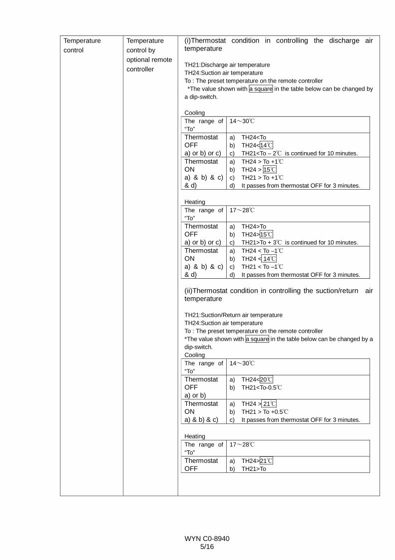
(i)Thermostat condition in controlling the discharge air temperature TH21:Discharge air temperature TH24:Suction air temperature To : The preset temperature on the remote controller *The value shown with a square in the table below can be changed by a dip-switch. Cooling The range of “To”
14~30℃
Thermostat OFF a) or b) or c)
a) TH24<To b) TH24<14℃ c) TH21<To – 2℃ is continued for 10 minutes.
Thermostat ON a) & b) & c) & d)
a) TH24 > To +1℃ b) TH24 > 15℃ c) TH21 > To +1℃ d) It passes from thermostat OFF for 3 minutes.
Heating The range of “To”
17~28℃
Thermostat OFF a) or b) or c)
a) TH24>To b) TH24>15℃ c) TH21>To + 3℃ is continued for 10 minutes.
Thermostat ON a) & b) & c) & d)
a) TH24 < To –1℃ b) TH24 < 14℃ c) TH21 < To –1℃ d) It passes from thermostat OFF for 3 minutes.
(ii)Thermostat condition in controlling the suction/return air temperature TH21:Suction/Return air temperature TH24:Suction air temperature To : The preset temperature on the remote controller *The value shown with a square in the table below can be changed by a dip-switch. Cooling The range of “To”
14~30℃
Thermostat OFF a) or b)
a) TH24<20℃ b) TH21<To-0.5℃
Thermostat ON a) & b) & c)
a) TH24 > 21℃ b) TH21 > To +0.5℃ c) It passes from thermostat OFF for 3 minutes.
Heating The range of “To”
17~28℃
Thermostat OFF
a) TH24>21℃ b) TH21>To
WYN C0-8940 6/16
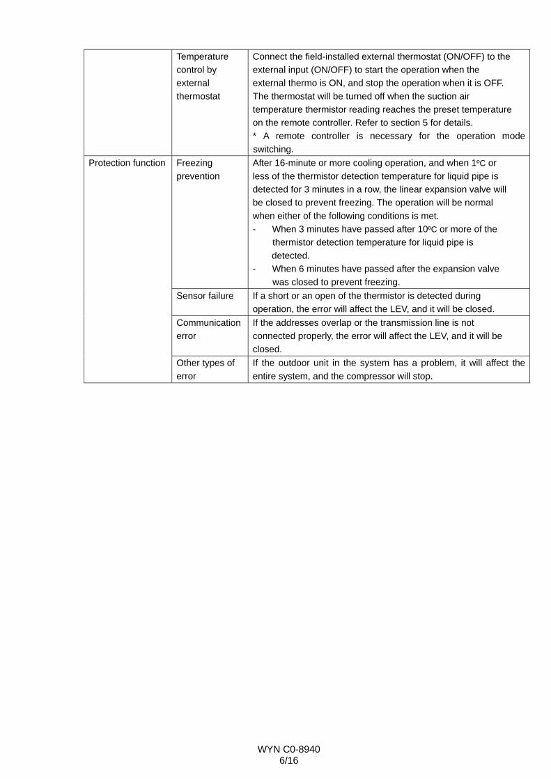
Temperature control by external thermostat
Connect the field-installed external thermostat (ON/OFF) to the external input (ON/OFF) to start the operation when the external thermo is ON, and stop the operation when it is OFF. The thermostat will be turned off when the suction air temperature thermistor reading reaches the preset temperature on the remote controller. Refer to section 5 for details. * A remote controller is necessary for the operation mode switching.
Freezing prevention
After 16-minute or more cooling operation, and when 1ºC or less of the thermistor detection temperature for liquid pipe is detected for 3 minutes in a row, the linear expansion valve will be closed to prevent freezing. The operation will be normal when either of the following conditions is met. - When 3 minutes have passed after 10ºC or more of the
thermistor detection temperature for liquid pipe is detected.
- When 6 minutes have passed after the expansion valve was closed to prevent freezing.
Sensor failure If a short or an open of the thermistor is detected during operation, the error will affect the LEV, and it will be closed.
Communication error
If the addresses overlap or the transmission line is not connected properly, the error will affect the LEV, and it will be closed.
Protection function
Other types of error
If the outdoor unit in the system has a problem, it will affect the entire system, and the compressor will stop.
WYN C0-8940 7/16
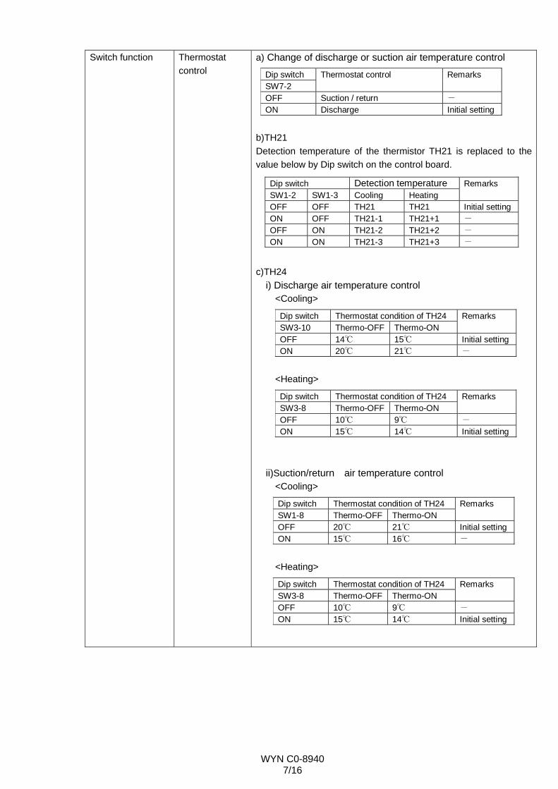
Switch function Thermostat control
a) Change of discharge or suction air temperature control
Dip switch SW7-2
Thermostat control Remarks
OFF Suction / return - ON Discharge Initial setting
b)TH21 Detection temperature of the thermistor TH21 is replaced to the value below by Dip switch on the control board.
Dip switch Detection temperature SW1-2 SW1-3 Cooling Heating
Remarks
OFF OFF TH21 TH21 Initial settingON OFF TH21-1 TH21+1 - OFF ON TH21-2 TH21+2 - ON ON TH21-3 TH21+3 -
c)TH24 i) Discharge air temperature control
<Cooling>
Dip switch Thermostat condition of TH24 SW3-10 Thermo-OFF Thermo-ON
Remarks
OFF 14℃ 15℃ Initial settingON 20℃ 21℃ -
<Heating>
Dip switch Thermostat condition of TH24 SW3-8 Thermo-OFF Thermo-ON
Remarks
OFF 10℃ 9℃ - ON 15℃ 14℃ Initial setting
ii)Suction/return air temperature control
<Cooling>
Dip switch Thermostat condition of TH24 SW1-8 Thermo-OFF Thermo-ON
Remarks
OFF 20℃ 21℃ Initial settingON 15℃ 16℃ -
<Heating>
Dip switch Thermostat condition of TH24 SW3-8 Thermo-OFF Thermo-ON
Remarks
OFF 10℃ 9℃ - ON 15℃ 14℃ Initial setting
WYN C0-8940 8/16
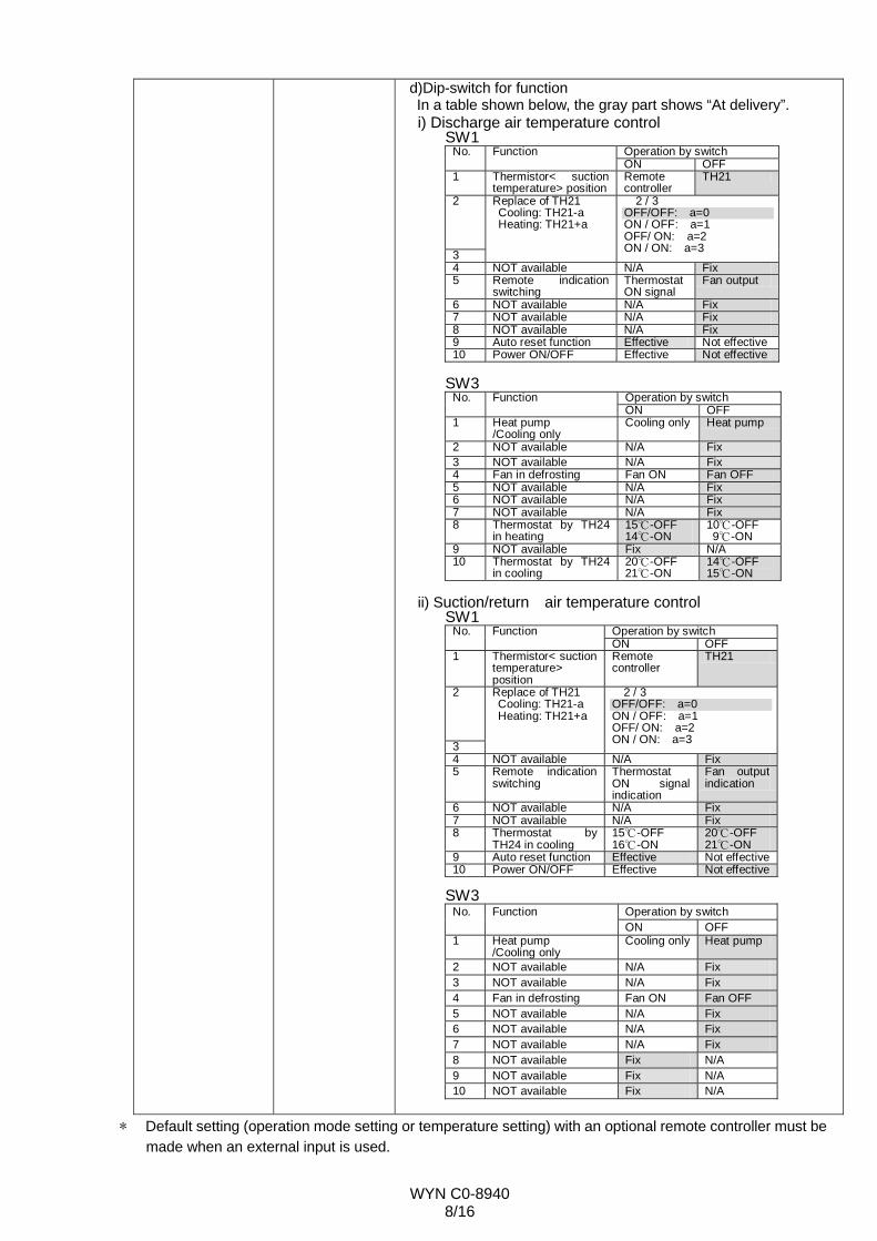
d)Dip-switch for function In a table shown below, the gray part shows “At delivery”.
i) Discharge air temperature control SW1
Operation by switch No. Function ON OFF
1 Thermistor< suction temperature> position
Remote controller
TH21
2
3
Replace of TH21 Cooling: TH21-a Heating: TH21+a
2 / 3 OFF/OFF: a=0 ON / OFF: a=1 OFF/ ON: a=2 ON / ON: a=3
4 NOT available N/A Fix 5 Remote indication
switching Thermostat ON signal
Fan output
6 NOT available N/A Fix 7 NOT available N/A Fix 8 NOT available N/A Fix 9 Auto reset function Effective Not effective10 Power ON/OFF Effective Not effective
SW3
Operation by switch No. Function ON OFF
1 Heat pump /Cooling only
Cooling only Heat pump
2 NOT available N/A Fix 3 NOT available N/A Fix 4 Fan in defrosting Fan ON Fan OFF 5 NOT available N/A Fix 6 NOT available N/A Fix 7 NOT available N/A Fix 8 Thermostat by TH24
in heating 15℃-OFF 14℃-ON
10℃-OFF 9℃-ON
9 NOT available Fix N/A 10 Thermostat by TH24
in cooling 20℃-OFF 21℃-ON
14℃-OFF 15℃-ON
ii) Suction/return air temperature control
SW1Operation by switch No. Function ON OFF
1 Thermistor< suction temperature> position
Remote controller
TH21
2
3
Replace of TH21 Cooling: TH21-a Heating: TH21+a
2 / 3 OFF/OFF: a=0 ON / OFF: a=1 OFF/ ON: a=2 ON / ON: a=3
4 NOT available N/A Fix 5 Remote indication
switching Thermostat ON signal indication
Fan output indication
6 NOT available N/A Fix 7 NOT available N/A Fix 8 Thermostat by
TH24 in cooling 15℃-OFF 16℃-ON
20℃-OFF 21℃-ON
9 Auto reset function Effective Not effective10 Power ON/OFF Effective Not effective
SW3
Operation by switch No. Function ON OFF
1 Heat pump /Cooling only
Cooling only Heat pump
2 NOT available N/A Fix 3 NOT available N/A Fix 4 Fan in defrosting Fan ON Fan OFF 5 NOT available N/A Fix 6 NOT available N/A Fix 7 NOT available N/A Fix 8 NOT available Fix N/A 9 NOT available Fix N/A 10 NOT available Fix N/A
* Default setting (operation mode setting or temperature setting) with an optional remote controller must be
made when an external input is used.
WYN C0-8940 9/16
4. Requirements on AHU design
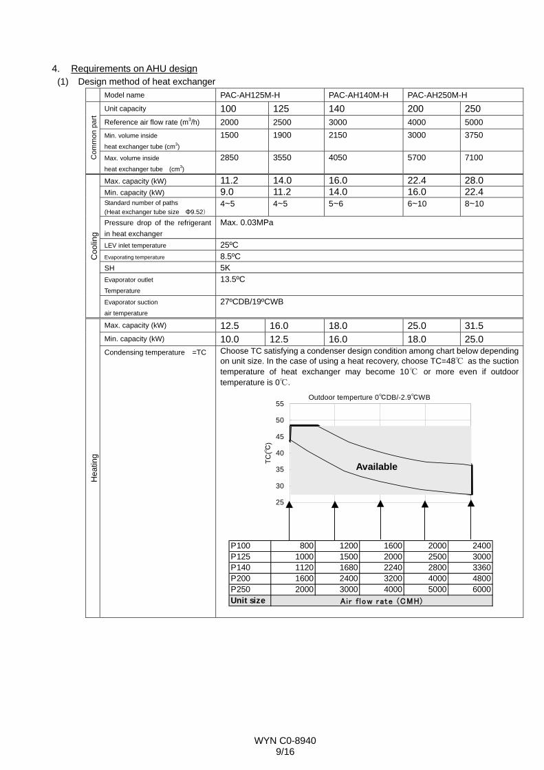
(1) Design method of heat exchanger Model name PAC-AH125M-H PAC-AH140M-H PAC-AH250M-H
Unit capacity 100 125 140 200 250 Reference air flow rate (m3/h) 2000 2500 3000 4000 5000 Min. volume inside
heat exchanger tube (cm3)
1500 1900 2150 3000 3750
Com
mon
par
t
Max. volume inside
heat exchanger tube (cm3) 2850 3550 4050 5700 7100
Max. capacity (kW) 11.2 14.0 16.0 22.4 28.0 Min. capacity (kW) 9.0 11.2 14.0 16.0 22.4 Standard number of paths (Heat exchanger tube size Φ9.52)
4~5 4~5 5~6 6~10 8~10
Pressure drop of the refrigerant in heat exchanger
Max. 0.03MPa
LEV inlet temperature 25ºC Evaporating temperature 8.5ºC SH 5K Evaporator outlet
Temperature
13.5ºC
Coo
ling
Evaporator suction
air temperature
27ºCDB/19ºCWB
Max. capacity (kW) 12.5 16.0 18.0 25.0 31.5 Min. capacity (kW) 10.0 12.5 16.0 18.0 25.0
Hea
ting
Condensing temperature =TC Choose TC satisfying a condenser design condition among chart below depending on unit size. In the case of using a heat recovery, choose TC=48℃ as the suction temperature of heat exchanger may become 10℃ or more even if outdoor temperature is 0℃.
25
30
35
40
45
50
55
2000 3000 4000 5000 6000
Air flow rate (CMH)
TC(℃
)
Outdoor temperture 0℃DB/-2.9℃WB
P100 800 1200 1600 2000 2400P125 1000 1500 2000 2500 3000P140 1120 1680 2240 2800 3360P200 1600 2400 3200 4000 4800P250 2000 3000 4000 5000 6000Unit size Air f low rate (CMH)
Available
WYN C0-8940 10/16
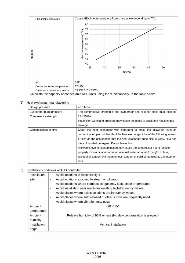
HEX inlet temperature Coose HEX inlet temperature from chart below depending on TC.
40
45
50
55
60
65
70
75
80
25 30 35 40 45 50
TC(℃)
Hex
inle
t tem
pera
ture
(℃
)
SC 15K Condensor outlet temperature TC-15
Hea
ting
Condensor suction air temperature 0℃DB / -2.9℃WB Calculate the capacity of connectable AHU units using the “Unit capacity” in the table above.
(2) Heat exchanger manufacturing Design pressure 4.15 MPa Evaporator burst pressure Compressive strength
The compressive strength of the evaporator and of other pipes must exceed 12.45MPa. Insufficient withstand pressure may cause the pipes to crack and result in gas leakage.
Contamination control Clean the heat exchanger with detergent to make the allowable level of contamination per unit length of the heat exchanger tube of the following values or less on the assumption that the heat exchanger tube size is Φ9.52. Do not use chlorinated detergent. Do not leave flux. Allowable level of contamination may cause the compressor not to function properly. Contamination amount: residual water amount 0.6 mg/m or less, residual oil amount 0.5 mg/m or less, amount of solid contaminants 1.8 mg/m orless
(3) Installation conditions of AHU controller
Installation site
- Avoid locations in direct sunlight. - Avoid locations exposed to steam or oil vapor. - Avoid locations where combustible gas may leak, settle or generated - Avoid installation near machines emitting high-frequency waves. - Avoid places where acidic solutions are frequency waves. - Avoid places where sulfur-based or other sprays are frequently used. - Avoid places where vibration may occur.
Ambient temperature
-20~43ºC
Ambient humidity
Relative humidity of 95% or less (No dew condensation is allowed)
Installation angle
Vertical installation
WYN C0-8940 11/16
(4) Cautions for installing LEV-kit Installation environment Avoid locations in direct sunlight. Installation angle Install the motor above the horizontal. Pipe size Φ9.52 (Brazing)
Use two LEVs when installing AH250. Connect two LEVs in parallel, and connect them to the appropriate refrigerant pipe according to the unit capacity.
Caution on brazing LEV can withstand only up to 120ºC. Cool the LEV while brazing. Wire connection - Connect the wire according to the wire color code to avoid miswiring. For
AH250, connect two wires to the same terminal. - Do not strain the power supply wires. - Be careful with the plate edge not to damage the wire. - The wire can withstand only up to 105ºC. Keep the wire away from
high-temperature part. - Bend the wire into "U" shape to prevent water from running down the wire andfrom dripping on the electrical components or the LEV.
(5) Cautions for installing thermistor
Installation site - Install the pipe thermistor properly so that it can accurately measure the pipetemperature. Protect it with the insulation material so that it is not affected by the temperature at other places.
- Install the liquid thermistor sensor at the evaporator inlet where the lowest temperature is found, as the thermistor is used to prevent freezing.
- Install the gas pipe thermistor at the junction of the evaporator outlet. - Install the suction air temperature thermistor at a place where the average
temperature of suction air into the evaporator can be measured. Wire connection - Connect the wire according to the terminal number to avoid miswiring.
- Do not strain the power supply wires. - Be careful with the plate edge not to damage the wire. - The wire can withstand only up to 105ºC. Keep the wire away from high-temperature part.
- Bend the wire into "U" shape to prevent water from running down the wire andfrom dripping on the electrical components or the thermistor.
(6) Other cautions
- The refrigerant temperature inside the evaporator may become 0ºC. Note that dew condensation on AHU main body or on the refrigerant pipe may occur.
- Drain the AHU properly. The temperature of AHU evaporator will drop and dew may condense on the AHU main body, if the LEV of AHU does not close due to malfunction in a system with one outdoor unit connected to a AHU controller, and if the AHU stopped and the other AHUs are in operation. Take appropriate measures against dew condensation to avoid serious damage to the unit.
- When a heater for heating operation is built-in and when both of the heater for heating operation and the heat exchanger are operated, the operation must be conducted within the inlet temperature range of the heat exchanger.
- Install an air filter on the heat exchanger. - Interlock the unit with the fan to prevent the refrigerant system from running when the fan stopped. - In a system with one outdoor unit connected to a AHU controller, the LEV of AHU will slightly open in
heating operation to prevent the refrigerant from accumulating inside the AHU heat exchanger, and the temperature of the AHU heat exchanger will slightly rise.
- In a system with one outdoor unit to which some AHU controllers are connected, the LEV will be temporarily open in heating operation to run the outdoor unit in defrost operation. In this case, low-temperature refrigerant will run inside the AHU heat exchanger, and the heating capacity
WYN C0-8940 12/16
of AHU which is running heating operation using the heater for heating operation will temporarily drop.
- In controlling the suction/return air temperature, capacity control is affected by the outdoor temperature. When the outdoor temperature drops, the discharge temperature also drops. Take proper measures to control the room temperature, to select the outlet position, and to prevent dew condensation.
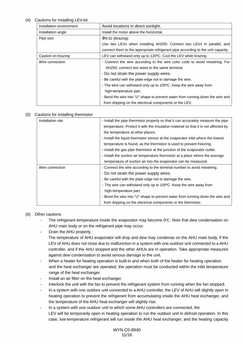
- In controlling the discharge air temperature, check the discharge air temperature of the low load capacity in middle season, because the thermostat may repeat ON/OFF. The targeted minimum capacity is 6kW. The minimum ΔT, which is the temperature difference between the inlet air temperature of the heat exchanger and discharge air temperature in heating mode, is shown as below chart. In cooling mode, ΔT is different depending on the SHF (As shown below, when SHF is 1, this is the ΔT at heating).
0
5
10
15
20
25
0 1000 2000 3000 4000 5000 6000
Air flow rate(CMH)
Min
imum
of Δ
T(K)
5. Requirements on interface with controller
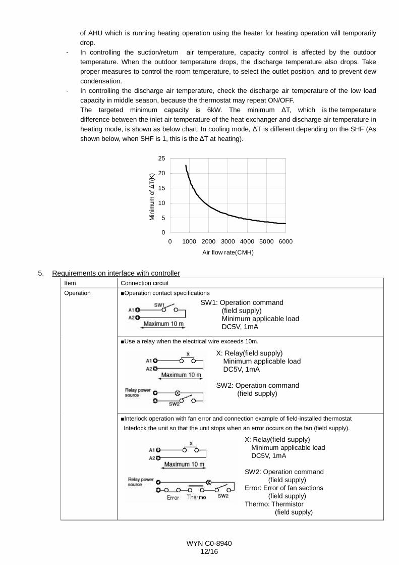
Item Connection circuit ■Operation contact specifications
SW1: Operation command (field supply) Minimum applicable load DC5V, 1mA
■Use a relay when the electrical wire exceeds 10m.
X: Relay(field supply) Minimum applicable load DC5V, 1mA
SW2: Operation command (field supply)
Operation
■Interlock operation with fan error and connection example of field-installed thermostat Interlock the unit so that the unit stops when an error occurs on the fan (field supply).
X: Relay(field supply) Minimum applicable load DC5V, 1mA
SW2: Operation command (field supply) Error: Error of fan sections (field supply) Thermo: Thermistor
(field supply)
WYN C0-8940 13/16
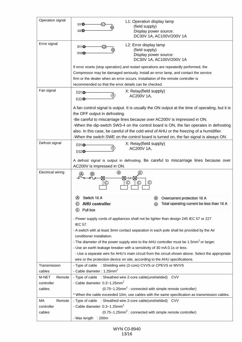
Operation signal
L1: Operation display lamp (field supply) Display power source: DC30V 1A, AC100V/200V 1A
Error signal
L2: Error display lamp (field supply) Display power source: DC30V 1A, AC100V/200V 1A
If error resets (stop operation) and restart operations are repeatedly performed, the Compressor may be damaged seriously. Install an error lamp, and contact the service firm or the dealer when an error occurs. Installation of the remote controller is recommended so that the error details can be checked.
Fan signal
X: Relay(field supply) AC200V 1A,
A fan control signal is output. It is usually the ON output at the time of operating, but it is the OFF output in defrosting. -Be careful to miscarriage lines because over AC200V is impressed in ON. -When the dip-switch SW3-4 on the control board is ON, the fan operates in defrosting also. In this case, be careful of the cold wind of AHU or the freezing of a humidifier. -When the switch SWE on the control board is turned on, the fan signal is always ON.
Defrost signal
X: Relay(field supply) AC200V 1A,
A defrost signal is output in defrosting. Be careful to miscarriage lines because over AC200V is impressed in ON.
Electrical wiring
- Power supply cords of appliances shall not be lighter than design 245 IEC 57 or 227 IEC 57.
- A switch with at least 3mm contact separation in each pole shall be provided by the Air conditioner installation.
- The diameter of the power supply wire to the AHU controller must be 1.5mm2 or larger. - Use an earth leakage breaker with a sensitivity of 30 mA 0.1s or less. - Use a separate wire for AHU’s main circuit from the circuit shown above. Select the appropriate wire or the protection device on site, according to the AHU specifications.
Transmission cables
- Type of cable : Shielding wire (2-core) CVVS or CPEVS or MVVS - Cable diameter : 1.25mm2
M-NET Remote controller cables
- Type of cable : Sheathed wire 2-core cable(unshielded) CVV - Cable diameter: 0.3~1.25mm2
(0.75~1.25mm2 : connected with simple remote controller) * When the cable exceeded 10m, use cables with the same specification as transmission cables.
MA Remote controller cables
- Type of cable : Sheathed wire 2-core cable(unshielded) CVV - Cable diameter: 0.3~1.25mm2
(0.75~1.25mm2 : connected with simple remote controller) - Max length : 200m
WYN C0-8940 14/16
CVVS, MVVS : PVC insulated PVC jacketed shielded control cable CPEVS : PE insulated PVC jacketed shielded communication cable CVV : PV insulated PVC sheathed control cable
6. Related cautions (1) Installation work
- Secure enough service space for replacement of the LEV and the thermistor. After an AHU controller is installed, address setting and unit capacity setting on the controller board switch is necessary. Refer to the installation manual for the setting method.
- Refer to the outdoor unit installation manual or the data book for installation of the outdoor unit. (2) Test run
- Turn on the main power of the unit at least 12 hours before test run to power the crankcase heater. Insufficient powering time may result in compressor damage.
- As the temperature setting and the operation mode setting are made at initial setting, a remote controller is necessary. Remove the remote controller after making the initial settings if it is not used. In case of PAR21MAA, remove the remote controller after turning off the power of the indoor and outdoor units. In case of PAR-27MEA, remove it after deleting the address of the remote controller. (Refer to the installation manual for remote controller for more details.)
(3) Operation control - Remove the connector inside the AHU controller when a local remote controller is used. When the
connector is connected, the controller will be in the remote operation mode, and the operation by the local remote controller will be prohibited.
- If the error lamp lights or the error display appears on the remote controller, do not reset an error by yourself. Contact the service firm or the dealer.
- Refer to the data book for system controller when using the system controller. (4) Service
- Regular maintenance is required to prolong the life of the units. It is recommended that the maintenance contract be concluded with a maintenance firm.
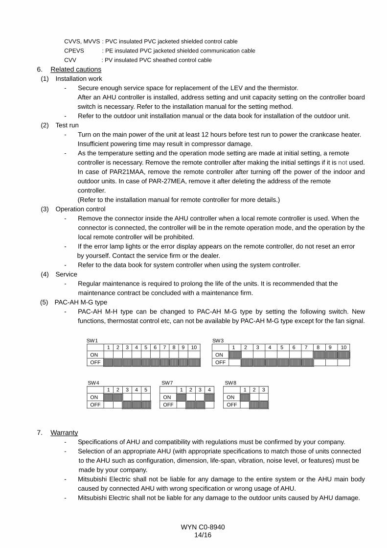
(5) PAC-AH M-G type - PAC-AH M-H type can be changed to PAC-AH M-G type by setting the following switch. New
functions, thermostat control etc, can not be available by PAC-AH M-G type except for the fan signal. SW1 SW3
1 2 3 4 5 6 7 8 9 10 1 2 3 4 5 6 7 8 9 10ON ON OFF OFF
SW4 SW7 SW8
1 2 3 4 5 1 2 3 4 1 2 3ON ON ON OFF OFF OFF
7. Warranty
- Specifications of AHU and compatibility with regulations must be confirmed by your company. - Selection of an appropriate AHU (with appropriate specifications to match those of units connected
to the AHU such as configuration, dimension, life-span, vibration, noise level, or features) must be made by your company.
- Mitsubishi Electric shall not be liable for any damage to the entire system or the AHU main body caused by connected AHU with wrong specification or wrong usage of AHU.
- Mitsubishi Electric shall not be liable for any damage to the outdoor units caused by AHU damage.
WYN C0-8940 15/16
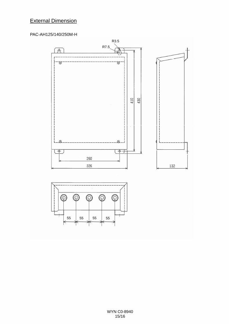
55 55 55 55
R3.5R7.5
External Dimension PAC-AH125/140/250M-H
WYN C0-8940 16/16
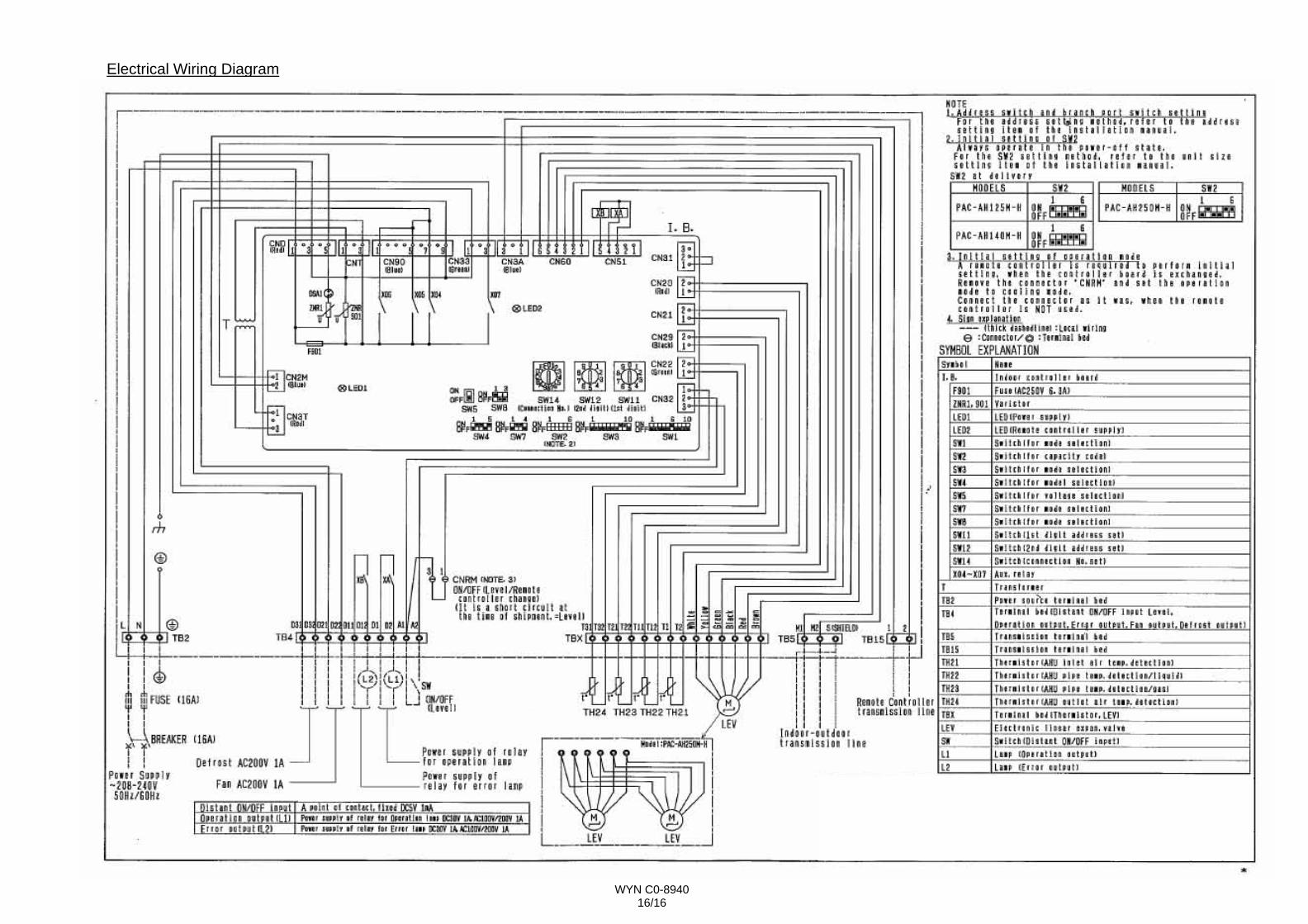
Electrical Wiring Diagram